


ORDER NO. ARP2932
PROJECTION COLOUR TELEVISION SD-T50W1 SD-T43W1
THIS MANUAL IS APPLICABLE TO THE FOLLOWING MODEL(S) AND TYPE(S).
| Tuno | Model | Peuver Requirement | Bomarka | ||
|---|---|---|---|---|---|
| туре | SD- T5 0W1 | SD-T43W1 | Hemarks | ||
| SL | 0 | 0 | AC110V/120-127V/220-230V/240V | ||
CONTENTS
- 1. SAFETY PRECAUTIONS ....................................
- 2. PRODUCT SAFETY NOTICE ....................................
- 3. CHARGED SECTION, HIGH VOLTAGE GENE-RATING POINT AND X - RAY PROTECTION ···· 4
- 4. EXPLODED VIEWS, PACKING AND PARTS LIST....................................
| 6. PCB PARTS LIST |
|---|
| 7. ADJUSTMENTS103 |
| 8. REPLACING THE CRT ASSY148 |
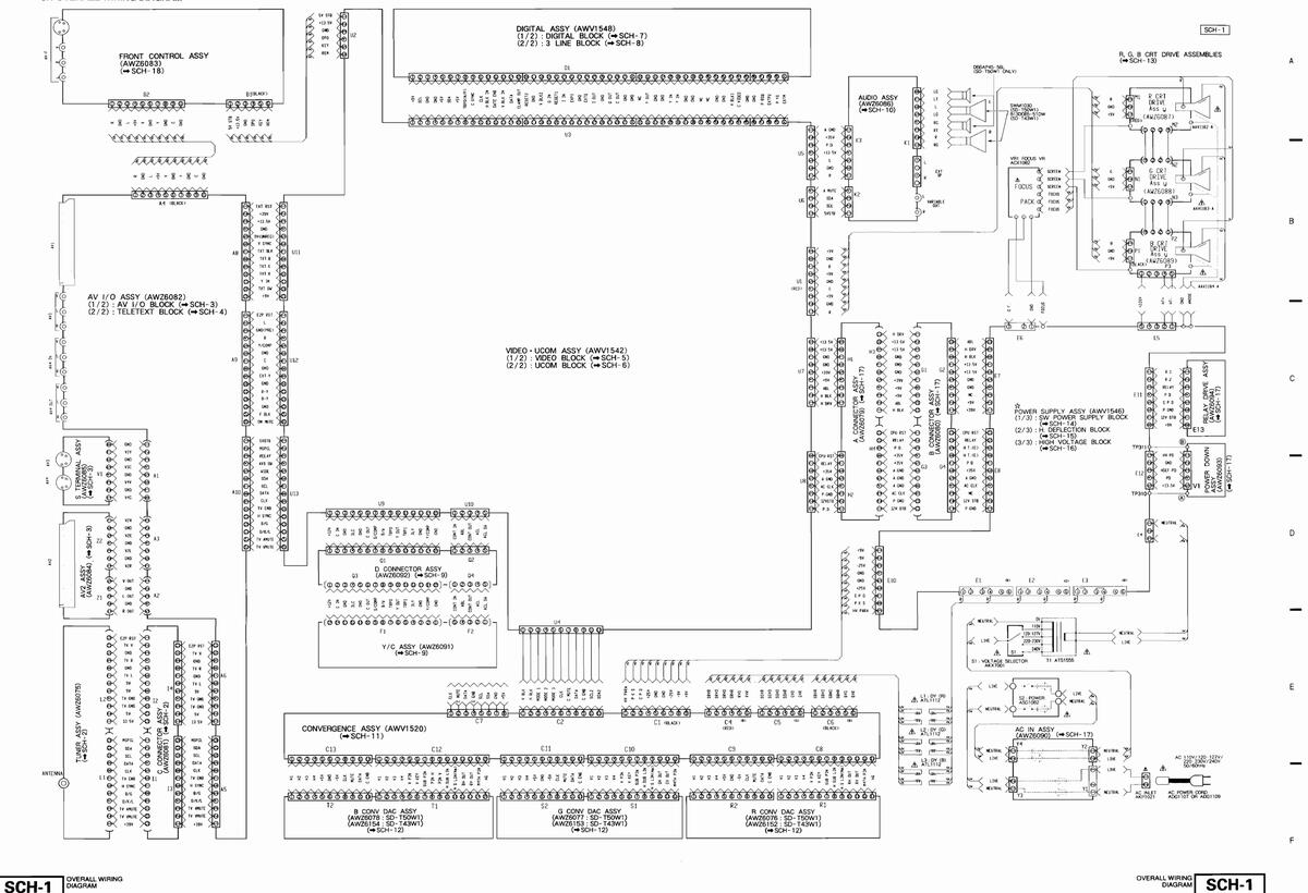
| 9. WIRING DIAGRAM······150 |
| 10. PANEL FACILITIES151 |
| 11. SPECIFICATIONS ······152 |
PIONEER ELECTRONIC CORPORATION 4-1, Meguro 1-Chome, Meguro-ku, Tokyo 153, Japan PIONEER ELECTRONICS SERVICE, INC. P.O. Box 1760, Long Beach, CA 90801-1760, U.S.A. PIONEER ELECTRONIC (EUROPE) N.V. Haven 1087, Keetberglaan 1, 9120 Melsele, Belgium PIONEER ELECTRONICS ASIACENTRE PTE. LTD. 501 Orchard Road, #10-00 Lane Crawford Place, Singapore 0923 © PIONEER ELECTRONIC CORPORATION 1996 0-ISC JUNE 1996 Printed in Japan
This service manual is intended for qualified service technicians; it is not meant for the casual do-it-yourselfer. Qualified technicians have the necessary test equipment and tools, and have been trained to properly and safely repair complex products such as those covered by this manual.
Improperly performed repairs can adversely affect the safety and reliability of the product and may void the warranty. If you are not qualified to perform the repair of this product properly and safely, you should not risk trying to do so and refer the repair to a qualified service technician.
WARNING
Lead in solder used in this product is listed by the California Health and Welfare agency as a known reproductive toxicant which may cause birth defects or other reproductive harm (California Health & Safety Code, Section 25249.5).
When servicing or handling circuit boards and other components which contain lead in solder, avoid unprotected skin contact with the solder. Also, when soldering do not inhale any smoke or fumes produced.
NOTICE
(FOR CANADIAN MODEL ONLY)
Fuse symbols - (fast operating fuse) and/or - (slow operating fuse) on PCB indicate that replacement parts must be of identical designation.
REMARQUE
(POUR MODÈLE CANADIEN SEULEMENT)
Les symboles de fusible - (fusible de type rapide) et/ou - (fusible de type lent) sur CCI indiquent que les pièces de remplacement doivent avoir la même désignation.
1. SAFETY PRECAUTIONS
NOTICE: Comply with all cautions and safety related notes located on or inside the cabinet and on the chassis or picture tube.
The following precautions should be observed
Do not install, remove, or handle the picture tube in any manner unless shatterproof goggles are worn. People not so equipped should be kept away while picture tubes are handled.
Keep picture tube away from the body while handling.
- 2. When service is required, even though the PROJE-CTION MONITOR RECEIVER an isolation transformer should be inserted between power line and the set in safety before any service is performed.
- 3. When replacing a chassis in the set, all the protective devices must be put back in place, such as barriers, nonmetallic knobs, adjustment and compartment covershields, isolation resistor-capacitor, etc.
- 4. When service is required, observe the original lead dress.
Extra precaution should be taken to assure correct lead dress in the high voltage circuitry area.
Always use the manufacturer's replacement components. Especially critical components as indicated on the circuit diagram should not be replaced by other manufacture's.
Furthermore where a short circuit has occurred, replace those components that indicate evidence of overheating.
6. Before returning a serviced set to the customer, the service technician must thoroughly test the unit to be certain that it is completely safe to operate without danger of electrical shock, and be sure that no protective device built into the set by the manufacturer has become defective, or inadvertently defeated during servicing.
Therefore, the following checks should be performed for the continued protection of the customer and service technician.
Leakage Current Cold Check
With the AC plug removed from the 110/120 - 127/220 - 230/240V AC 50/60Hz source, place a jumper across the two plug prongs. Turn the AC power switch on. Using an insulation tester (DC 500V), connect one lead to the jumpered AC plug and touch the other lead to each exposed metal part (input/output terminals, screwheads, metal overlays, control shafts, etc.), particularly any exposed metal part having a return path to the chassis. Exposed metal parts having a return path to the chassis should have a minimum resistor reading of 0.3MΩ and a maximum resistor reading of 5MΩ. Any resistor value below or above this range indicates an abnormality which requires corrective action. Exposed metal parts not having a return path to the chassis will indicate an open circuit.
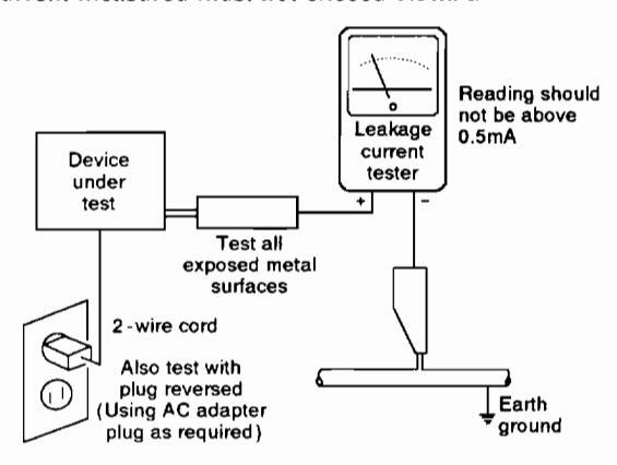
Leakage Current Hot Check
Plug the AC line cord directly into a 110/120 - 127/220 - 230/240V AC 50/60Hz outlet ( do not use an isolation transformer for this check). Turn the AC power switch on. Using a "Leakage Current Tester(Simpson Model 229 equivalent)", measure for current from all exposed metal parts of the cabinet(input/output terminals, screwheads, metal overlays, control shaft, etc.), particularly any exposed metal part having a return path to the chassis, to a known earth ground(water pipe, conduit, etc.). Any current measured must not exceed 0.5mA.
AC Leakage Test
ANY MEASUREMENTS NOT WITHIN THE LIMITS OUTLINED ABOVE ARE INDICATIVE OF A POTENTIAL SHOCK HAZARD AND MUST BE CORRECTED BEFORE RETURNING THE SET TO THE CUSTOMER.
High Voltage
This set is provided with a X-ray protection for clearly indicating that voltage has increased in excess of a predetermined value. Comply with all notes described in this Service Manual regarding this hold down circuit when servicing, so that this X-ray protection may correctly be operated.
Serviceman Warning
In the status of the black picture (video muting is being applied) when no signal is input, high voltage of this set during operation is less than 30.9kV. In case any component having some relation to the high voltage is replaced, confirm that the high voltage is lower than 30.9kV in the status of the black picture when no signal is input
To measure H.V. use a high impedance H.V. meter. Connect (-) to earth and (+) to the FBT anode cable connector. (Refer to page 145.)
X-radiation
TUBE: The primary source of X - radiation in this set is the picture tube.
For continued X - radiation protection, the replacement tube must be the same type as the original, PIONEER approved type.
The picture tube (CRT assy R, G, B) used in this set holds complete guarantee against X-ray radiation when the Xray is sealed (See page 4). Accordingly, when the current in flowing to the picture tube (CRT assy R, G, B), be sure to perform it by putting the tube into X-ray sealed applied state. Avoid absolutely to flow the current to the picture tube (CRT assy R, G, B) itself. Moreover, when the voltage of the high voltage circuit becomes abnormally a little higher, the picture tube radiates X-rays. Accordingly, when servicing the high voltage circuit be sure to replace as an assy with the POWER SUPPLY assy in the manner in which has been adjusted to perform normal operation.
2. PRODUCT SAFETY NOTICE
Many electrical and mechanical parts in PIONEER set have special safety related characteristics. These are often not evident from visual inspection nor the protection afforded by them necessarily can be obtained by using replacement components rated for higher voltage, wattage, etc. Replacement parts which have these special safety characteristics are identified in this Service Manual.
Electrical components having such features are identified by marking with a A on the schematics and on the parts list in this Service Manual.
The use of a substitute replacement component which does not have the same safety characteristics as the PIONEER recommended replacement one, shown in the parts list in this Service Manual, may create shock, fire, X-radiation, or other hazards.
Product Safety is continuously under review and new instructions are issued from time to time. For the latest information, always consult the current PIONEER Service Manual. A subscription to, or additional copies of PIONEER Service Manual may be obtained at a nominal charge from PIONEER.
3. CHARGED SECTION, HIGH VOLTAGE GENERATING POINT AND X-RAY PROTECTION
Charged section
The circuit in which the commercial AC power is used as it is without passing through the power supply transformer If the charged section is touched, there is a risk of electric shock. In addition, the measuring equipment can be damaged if it is connected to the GND of the charged section and the GND of the non-charged section while connecting the set directly to the commercial AC power supply. In this case, be sure to connect the set via an insulated transformer and supply the current.
Charged section
(Power supply primary side)
- 1 The primary side of the POWER SUPPLY assy
- 2 AC nower cord
- 3 MAIN POWER switch (S2)
- 4 AC inlet
- 5 AC IN accu
- 6 Voltage selector (S1)
- 7 Power transformer (T1)

Fig. 1 Charged section and high voltage generating section
High voltage generating point
The place where voltage of over 100V is generated.
- 1 Charged section
- 2 POWER SUPPLY assy
-
(including FBT) (30.5kV 135V) 3. R. CRT DRIVE assy (10.5kV)4. G. CRT DRIVE assy (10.5kV)5. B. CRT DRIVE assy (10.5kV)6. CRT assy R (30.5kV) 7 CRT assy G (30.5kV)
- 8. CRT assy B (30.5kV)
- 9. Focus variable resistor (VR1) (10.5kV)
- 10. Deflection vokes (L1, L2, and L3) / Approx
1100V at peak
X-ray protection
- Regarding the parts which are relative to radiation of X-rays (There is the danger to radiate X-ray from the individual CRT assy R, G, B), there are notifications of caution in the individual schematic diagrams. Be sure to read them for safety's sake
- The component parts for X ray protection are as follows When the current flows to the CRT assy R G B be sure to perform it with these parts being attached. Protection from the X-ray radiation is maintained in the state in which these parts have been installed to the CRT assy R. G. B. Accordingly, never supply current only to the CRT assy R. G. B
Moreover, the anode voltage of the CRT assy R. G. B. should always be kept not higher than the predetermined value (in the minimum brightness and picture state when non signal input is higher than 30.9kV). Be sure to drive the CRT assy R, G, B by using a completely functional POWER SUPPLY assy which have been adjusted completely in the combined state. (When the voltage abnormally becomes high, the X-ray protection circuit will operate)
- 1. CRT assy R. G. B(Do not dismantle CRT assemblies under any circumstances).
- 2. Each Lens assy

Fig. 2 Component parts for X - ray protection
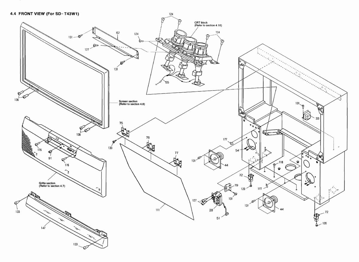
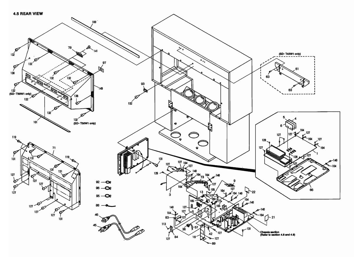
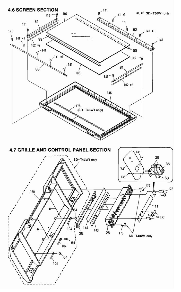
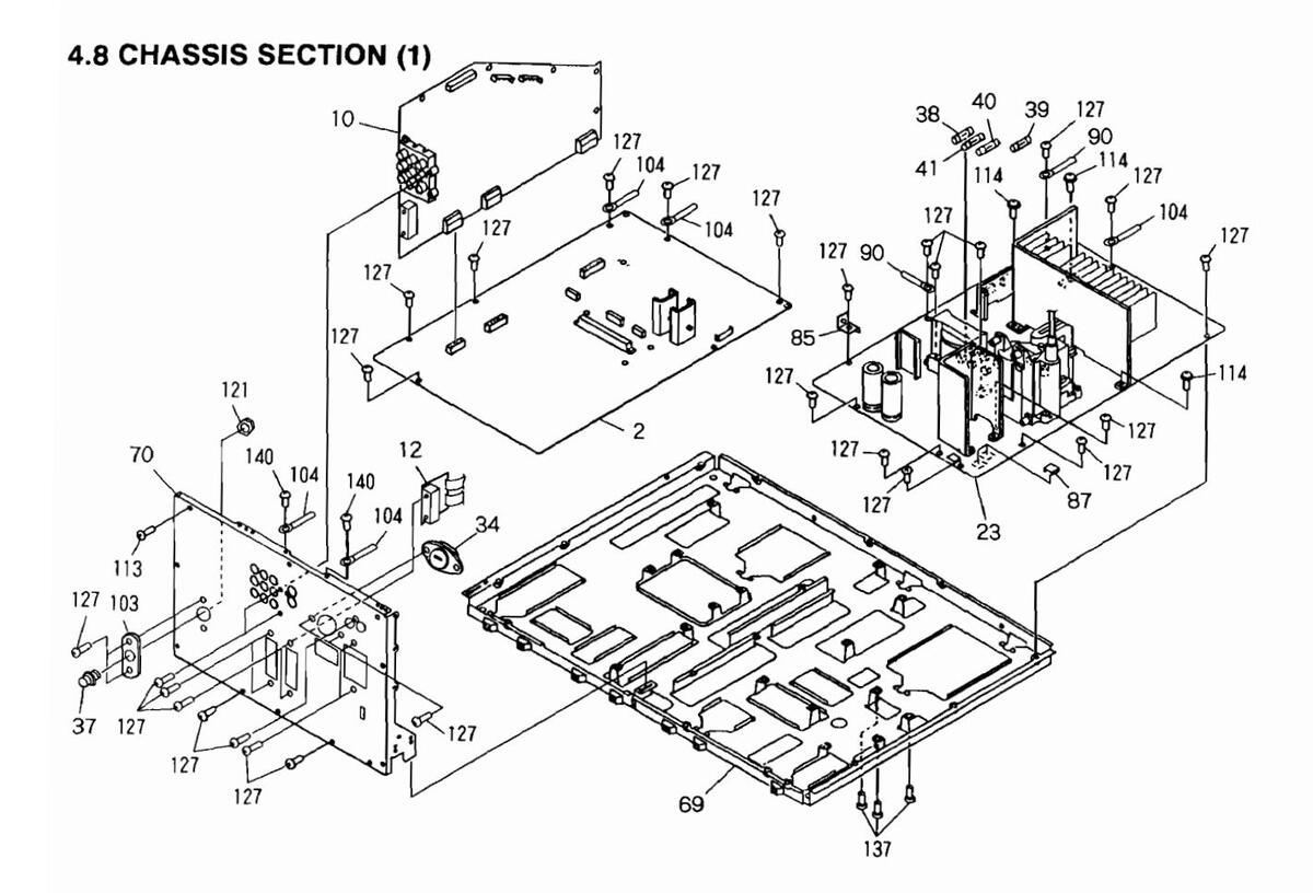
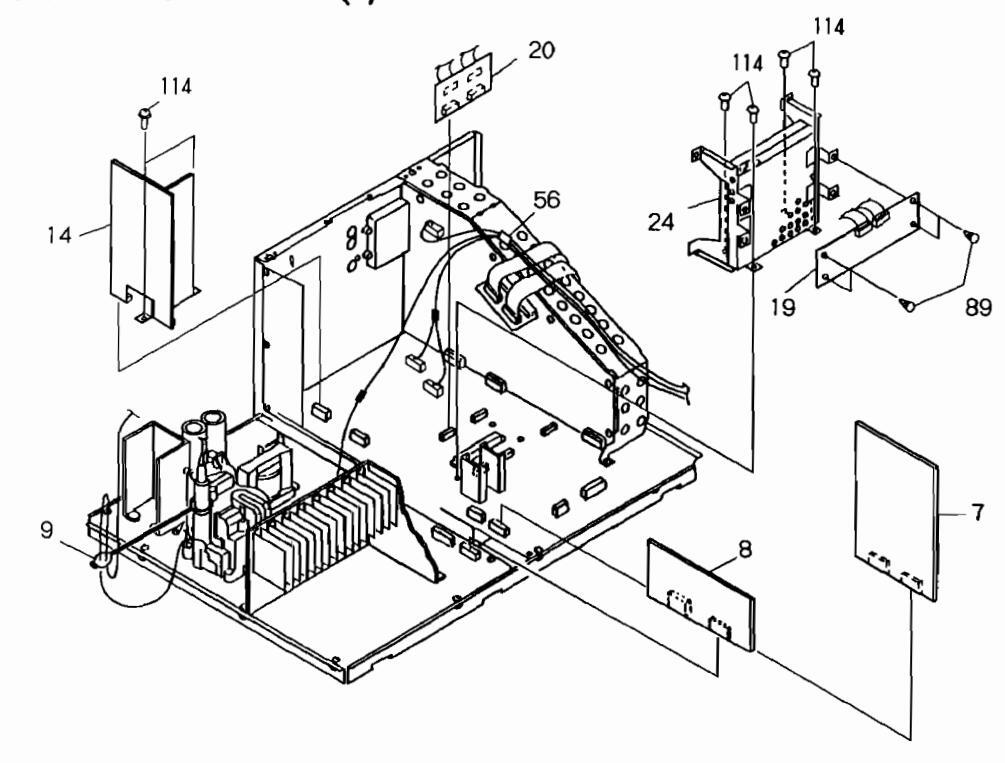
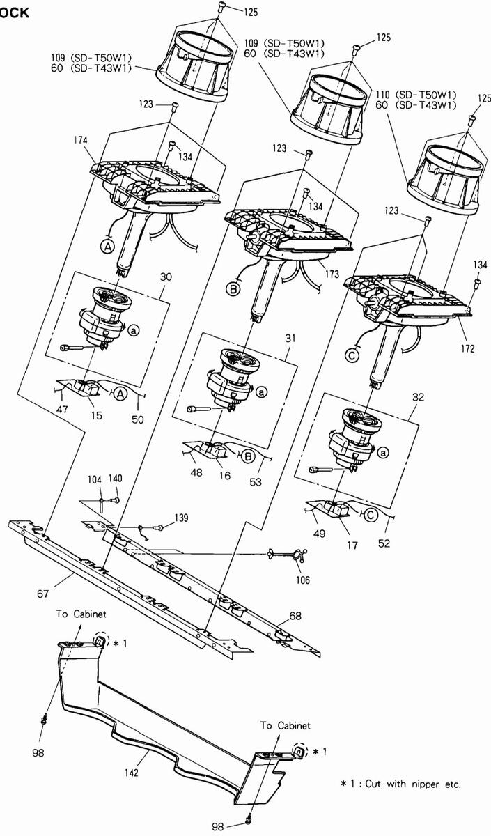
4. EXPLODED VIEWS, PACKING AND PARTS LIST
NOTES
- Parts marked by "NSP" are generally unavailable because they are not in our Master Spare Parts List.
- The A mark found on some component parts indicates the importance of the safety factor of the part. Therefore, when replacing, be sure to use parts of identical designation.
- Parts marked by " " are not always kept in stock. Their delivery time may be longer than usual or they may be unavailable.
- Parts marked by $$\phi$ are important parts which relate to X-rays radiation.
- If any of these parts need to be replaced, always replace with specified parts.
4.1 PARTS LIST
| Mark | No. | Description | Part No. | Mark | No. | Description | Part No. |
|---|---|---|---|---|---|---|---|
| 1 | CONVERGENCE ASSY | AWV1520 | 43 | SPEAKER 66 (SD-T50W1 ONLY) | D66AP45-56L | ||
| 2 | VIDEO-UCOM ASSY | AWV1542 | 44 | SPEAKER 12 (SD-T50W1) | SWM1030 | ||
| 3 | TUNER ASSY | AWZ6075 | 44 | SPEAKER 12 (SD-T43W1) | B13DC65-51DW | ||
| 4 | R CONV DAC ASSY (SD-T50W1) | AWZ6076 | ٨ | 45 | AC POWER CORD | ADG1107 | |
| 4 | R CONV DAC ASSY (SD-T43W1) | AWZ6152 | Ā | 46 | AC POWER CORD | ADG1109 | |
| 1 | 1. DOTOD | ADOTTOU | |||||
| 5 | G CONV DAC ASSY (SD-T50W1) | A\26077 | 47 | J2 1P LEAD WIRE | ADX1307 | ||
| 5 | G CONV DAC ASSY (SD-T43W1) | AWZ6153 | 48 | J3 1P LEAD WIRE | ADX1308 | ||
| 6 | B CONV DAC ASSY (SD-T50W1) | AWZ6078 | 49 | J4 1P LEAD WIRE | ADX1309 | ||
| 6 | B CONV DAC ASSY (SD-T43W1) | A\Z6154 | ⚠ | 50 | J5 1P LEAD WIRE | ADX1310 | |
| 7 | A CONNECTOR ASSY | AWZ6079 | 51 | J8 4P HOUSING WIRE | ADX1315 | ||
| 8 | B CONNECTOR ASSY | AWZ6080 | ٨ | 52 | J7 1P LEAD WIRE | ADX2173 | |
| Ğ | C CONNECTOR ASSY | AWZ6081 | * | 53 | 16 1P LEAD WIRE | ADX2174 | |
| 10 | AV I/O ASSY | AWZ6082 | 54 | 19 8P LEAD WINT HOUSING | ADX2221 | ||
| 11 | FRONT CONTROL ASSY | AW76083 | 01 | NDKEEDI | |||
| 12 | AND ACCY | AW76084 | 5.4 | 4082222 | |||
| 12 | AV2 A331 | A#20004 | 34 | (SD-T43W1) | RUALLLL | ||
| NSP | 13 | S TERMINAL ASSY | AWZ6085 | ||||
| 14 | AUDIO ASSY | AWZ6086 | 55 | J18 WIRE HARNESS A | ADX2242 | ||
| 15 | R CRT DRIVE ASSY | AWZ6087 | 56 | 119 WIRE HARNESS B | ADX2243 | ||
| 16 | G CRT DRIVE ASSY | AW26088 | 57 | 110 3P LEAD WINT HOUSING | ADX2244 | ||
| 17 | B CRT DRIVE ASSY | AWZ6089 | 58 | III WIRE HARNESS C | ADX2244 | ||
| 17 | B CRI DRIVE ADDI | A#20003 | 50 | PAPER SHEET (50) | AUR1151 | ||
| 19 | AC IN ASSY | 1876000 | 55 | (SD_TAREI ONLY) | ANDITOT | ||
| 10 | AWZ60090 | ||||||
| 19 | AW20091 | C 0 | LENC ACCV (10) | MD9COA | |||
| 20 | D CONNECTOR ASSI | AWZ6092 | ¥ | 60 | LENS ASSI (40) | AMRZ6U4 | |
| 21 | POWER DOWN ASSI | AWZ6093 | 61 | (SD-143W1 UNLI) | 1100070 | ||
| 22 | RELAY DRIVE ASSY | AW26094 | 61 | (SD-T43W1 ONLY) | AMR28/3 | ||
| ~ | 23 | POWER SUPPLY ASSY | AWV1546 | NSP | 62 | FRONT COVER PANEL | ANG1953 |
| ~ | 24 | DIGITAL ASSY | AWV1548 | (SD-T43W1 ONLY) | |||
| 25 | DOOR | AAN1416 | |||||
| 26 | CONTROL PANEL | AMR2524 | 63 | SCREW (SD-T43W1 ONLY) | BYCAOP180FMC | ||
| 20 | AmDGUZA | 64 | SCREW (SD-T43W1 ONLY) | VP730P080FMC | |||
| 21 | ٨ | 65 | 1) ANODE CABLE | ADV1019 | |||
| A | 20 | VD1 FOCUS VP | 1082 | 66 | AD11012 | ||
| 20 | ACC7000 | NCD | 67 | COT EDGNT EDAME (ED) | ANA 1433 | ||
| 29 | LI DEELECTION YOKE | ACG7009 | NSP | 01 | (SD TEOWI) | ANAISII | |
| 30 | (SD-150W1) | ||||||
| 31 | LZ DEFLECTION YORE | AILIIIZ | NOD | ||||
| Δ | 32 | L3 DEFLECTION YOKE | ATLITIZ | NSP | 61 |
CRT_FRONT_FRAME
(SD-T43W1) |
ANA1494 |
| Â | 33 | T1 POWER TRANSFORMER | ATS1555 | NSP | 68 | CRT REAR FRAME (50) | ANA1512 |
| 1 | 34 | S1 VOLTAGE SELECTOR | AKX7001 | nor | 00 | (SD-T50W1) | AUTO 10 |
| 7 | 35 | S2 POWER SWITCH | ASG1082 | NSP | 68 | CRT REAR FRAME | ANA 1495 |
| /\ | 20 | AKD102 | NOL | 00 | (SD-TA2W1) | ANA1455 | |
| 20 | IF AC INCEI | AKT 1021 | (SD-145W1) | ||||
| NSP | 57 | FAL SULLEI | MA-202 | NSP | 69 | CHASSIS ASSY | ANA 1526 |
| ٨ | 3.8 | FULLOG FUSE (TROOM& 250V) | AFK-507 | 101 | 70 | REAR PANEL (SD-T50W1) | ANC2276 |
| ^ | 30 | FUID2 FUSE (TAA 250V) | AFK-514 | 70 | REAR PANEL (SD-TASWI) | ANC2277 | |
| ^ | 10 | FULOS FUSE (TAK 250V) | AFK-51A | NSP | 71 | BACK COVER PLATE | ANE 1520 |
| A | 40 | FUID7 FUSE (T6 24 250V) | AEK-516 | Nor | 72 | CASTED | AMD 2720 |
| 41 |
FUIDI FUSE(ID. SA, 2307)
FUGD1 FUSE(TA SA SEOV) |
AEK-010 | 12 | CASIER | AMIN 2129 | ||
| /1\ | 46 | FUSUI FUSE(IO. SM, 23UV) | VEV1032 |
| Mark | No. | Description | Part No. | Mark | No. | Description | Part No. |
|---|---|---|---|---|---|---|---|
| NSP | 73 | PCB_FRAME | ANG1849 | 111 | MIRROR (SD-750W1) | AMR2850 | |
| NSP | 74 | SWITCH HOLDER | ANG1945 | 111 | MIRROR (43) (SD-T43W1) | AMP2813 | |
| NCD | 75 | MIDDOD UDDED STAV I | 110 | AMIN 2013 | |||
| NOD | 10 | MIRROR UPPER STAT L | ANO1940 | 112 | SCREW (SIEEL) | ABAIUZU | |
| NSP | 76 | MIRROR UPPER STAY C | ANG1947 | 113 | SCREW (STEEL) | ABA1089 | |
| NSP | 77 | MIRROR UPPER STAY R | ANG1948 | 114 | SCREW | ABA1099 | |
| NSP | 78 | MIRROR UNDER STAY | ANG1949 | 115 | SPECIAL SCREW | ABA1121 | |
| NSP | 79 | VR HOLDER | ANG1956 | 116 | • | ||
| NSP | 80 | SCREEN HOLDER H (50) | ANG2029 | 117 | SPECIAL SCREW(FE) | ABA1198 | |
| NSP | 80 |
(SD-T50¥1)
SCREEN HOLDER H (43) |
ANG2025 | 11.8 |
(SD-T50₩1 ONLY)
SCRF₩ |
ADA1210 | |
| NO1 | 00 | (SD-T43W1) | 102023 | 110 | SCREW | ADA1215 | |
| NOD | 119 | SCREW | ABA1224 | ||||
| NSP | 81 | SCREEN HULDER V (50) | ANG2030 | 120 | SCREW (SD-T50W1) | BYC40P250FMC | |
| (SD-T50\1) | 120 | SCREW (SD-T43W1) | BYC40P120FZK | ||||
| NSP | 81 | SCREEN HOLDER V (43) | ANG2026 | 121 | HEXAGONAL DUCT NUT | ABN-087 | |
| (SD-T43₩1) | 122 | SCREW | ABZ30P080FZK | ||||
| NSP | 82 | SCREEN HOLDER UH (50) | ANG2031 | ||||
| • | (SD-T50W1) | 123 | SCREW | 487/00120FMC | |||
| 120 | SCDEW | ACZ ADDOROENC | |||||
| NCD | 0.0 | SCREEN HOLDED HH (12) | ANC2027 | 104 | SCREW SCREW | ACZ40PU80PMC | |
| Nor | 02 | SCREEN HOLDER UN (43) | ANGZUZI | 145 | SCREW | AMZ4UPU8UFZK | |
| (SD-143W1) | 126 | SCREW | BBZ30P080FCU | ||||
| NSP | 83 | AC IN ASSY HOLDER | ANG2060 | 127 | SCREW | BBZ30P080FZK | |
| NSP | 84 | CORD PLATE | ANG2061 | ||||
| NSP | 85 | PCB HOLDER (S) | ANG2062 | 128 | SCREW | BBZ30P100FMC | |
| NSP | 86 | BOTTOM RAIL HOLDER | ANG2082 | 129 | SCREW (SD-T50W1 ONLY) | BYC35P120FZK | |
| (SD-T50₩1_ONLY) | 130 | SCREW (SD-T50W1 ONLY) | BYC35P160F7K | ||||
| 131 | SCREW | BYCAODI 20F7K | |||||
| 87 | SHIFLD COVER | ANH1166 | 132 | SCDE# | DIC40112012A | ||
| 01 | NYLON DINDED | ADC 001 | 152 | SCREW | DIC40P140F2K | ||
| 00 | NILUN DINUER | AEC-093 | 100 | 6000 F | BUG ( 0 - 1 - 0 - 1 - | ||
| 89 | RIVEL | AEC-441 | 133 | SCREW | BYC40P160FMC | ||
| 90 | BINDER | AEC-826 | 134 | SCREW | FBT40P120FZK | ||
| 91 | CATCHER | AEC1012 | 135 | SCREW | PMB30P080FZK | ||
| 136 | SCREW | PMB50P250FZB | |||||
| NSP | 92 | PURSE LOCK S | AEC1261 | • | 137 | SCREW | PPZ40P120FMC |
| NSP | 93 | NYLON CLAMPER | AEC1321 | ||||
| NSP | 94 | CABLE CLIP | AFC1369 | 138 | SCREW | PVC AOT 1 AOF 79 | |
| NCD | 05 | AEC1492 | 120 | SCIEW | VDT20D000C2K | ||
| 1101 | 50 | DUDGE LOCK L | AEC1540 | 133 | VDI JUPUOUP ZK | ||
| 90 | FURSE LOCK | AEC1340 | 140 | SCREW | VCZ30P060FMC | ||
| 141 | SCREW | VPZ40P120FMC | |||||
| 97 | SPACER (PVC) | AEC1594 | NSP | 142 | TRAY (PLS) | AMR2563 | |
| 98 | RIVET (PLASTIC) | AEC1608 | |||||
| 99 | SCREEN SPACER 50(PVC) | AEC1641 | 143 | CONTROL SHEET | AAK2668 | ||
| (SD-T50W1) | 144 | INDICATOR PANEL(SD-T50W1) | AAK2669 | ||||
| 99 | SCREEN SPACER (PVC) | AEC1639 | 144 | INDICATOR PANEL (SD-T43W1) | AAK2670 | ||
| 00 | (SD-TA3W1) | hborooo | 145 | BADGE (SD_T50W1 ONLY) | AAM1069 | ||
| (50 145#1) | 140 | SCREEN EDANE(ED) | AMDOLOO | ||||
| 100 | CUCULON A | 1001010 | 140 | SCREEN FRAME(SU) | AMBZ59Z | ||
| 100 | CUSHION A | AEC 1043 | (SD-150W1) | ||||
| 101 | CUSHION B | AEC1644 | |||||
| 102 | SPACER(PVC)(SD-T50W1 ONLY) | AEC1652 | 146 | SCREEN FRAME(43) | AMB2571 | ||
| 103 | SPACER (PVC) | AEC1654 | (SD-T43W1) | ||||
| 104 | BINDER | AEP-215 | 147 | BOTOM RAIL 51 (SD-T50W1) | AMR2861 | ||
| 147 | BOTOM RAIL (43) (SD-T43W1) | AMR2860 | |||||
| 105 | RIVET (PLASTIC) | AEP-236 | 148 | • | 11.112000 | ||
| NCD | 106 | AED-320 | 140 | ||||
| 101 | 100 | AMD 27 99 | 140 | NIPPOR CASE | AND 2002 | ||
| 107 | AMD2770 | 149 | MIRROR CASE | AMEZZ9Z | |||
| 107 | rkesnel (43W) (SD-T43WI) | AMKZIIS | 150 | GRILLE 51 (SD-T50W1) | AMR2711 | ||
| 108 | LENTICULAR SHEET (50W) | AMR2858 | 150 | GRILLE ASSY(43)(SD-T43W1) | AMR2688 | ||
| (SD-T50\1) | NSP | 151 | BLIND PLATE(SD-T50W1 ONLY) | ) AMR2794 | |||
| 152 | OPERATING INSTRUCTIONS | ARB1500 | |||||
| 108 | LENTICULAR SHEET(43W) | AMR2685 | (ENGLISH) | ||||
| (SD-T43W1) | , | ||||||
| * | 109 | LENS ASSY (G) | AMR2388 | 152 | |||
| 2 | 103 | 1002000 | NCD | 154 | CONVER CAUTION | ADM1112 | |
| ~ | 110 | AMD 22 90 | NOF | 154 | CAUTION LADEL GOOD | ||
| ¥ | 110 | AMIL7903 | NSP | 122 | CAULTON LABEL ZZUY | ARKIUUZ | |
| (SD-T50W1 ONLY) | NSP | 156 | WARRANTY CARD | ARW1020 | |||
| 157 |
| Mark | No. | Description | Part No. |
|---|---|---|---|
| 158 |
REMOTE CONTROL UNIT
(CU-SD097) |
AXD1424 | |
| 159 | CASTER PLATE | AEC1025 | |
| NSP | 160 | BATTERY (RO3, AAA) | AEX-021 |
| 161 | UNDER PAD ASSY (SD-T50W1) | AHA2093 | |
| 161 | UNDER PAD ASSY (SD-T43W1) | AHA2034 | |
| 162 | UPPER PAD ASSY (SD-T50W1) | AHA2094 | |
| 162 | UPPER PAD ASSY (SD-T43W1) | AHA2035 | |
| 163 |
CYLINDRICAL SUPPORT
(SD-T50W1) |
AHB1168 | |
| 163 |
CYLINDRICAL SUPPORT
(SD-T43W1) |
AHB1142 | |
| NSP | 164 | CU PACKING CASE | AHC1027 |
| 165 | UPPER CARTON (SD-T50W1) | AHD2846 | |
| 165 | UPPER CARTON (SD-T43W1) | AHD2847 | |
| 166 | UNDER CARTON (SD-T50W1) | AHD2866 | |
| 166 | UNDER CARTON (SD-T43W1) | AHD2811 | |
| NSP | 167 | PACKING SHEET | AHG1036 |
| NSP | 168 | MANUAL BAG | AHG1083 |
| NSP | 169 | VINYL SEAT L | AHG1110 |
| NSP | 170 | PACKING SHEET | AHG1232 |
| 171 | • | ||
| ≜☆ | 172 | CRT ASSY 50(B) (SD-T50W1) | AWY1349 |
| ⚠☆ | 172 | CRT ASSY (43B) (SD-T43W1) | AWY1303 |
| ≜∆☆ | 173 | CRT ASSY 50(G) (SD-T50W1) | AWY1369 |
| ∆☆ | 173 | CRT ASSY (43G) (SD-T43W) | 1)AWY1304 |
| ⚠☆ | 174 | CRT ASSY 50(R) (SD-T50W1) | AWY1370 |
| ≜∆ | 174 | CRT ASSY (43R) (SD-T43W1) | AWY1305 |
| 175 | BATTERY COVER | AZN2237 | |
| 176 | SCREW (SD-T43W1 ONLY) | ABZ40P120FZK | |
| 177 |
BLIND SPACER(PVC)
(SD-T43W1 ONLY) |
AEC1605 | |
| 178 | CUSHION C (SD-T43W1 ONLY) | AEC1645 | |
| 179 | BIND (SD-43W1 ONLY) | AED1161 | |
| NSP | 180 | PAD (SD-T43W1 ONLY) | AHA2073 |
4.2 PACKING

SD-T50W1,SD-T43W1

4.9 CHASSIS SECTION (2)
4.10 CRT BLOCK
5. SCHEMATIC AND PCB CONNECTION DIAGRAMS
NOTE FOR SCHEMATIC DIAGRAMS
(Type 5A) 1. When ordering service parts, be sure to refer to "PARTS LIST of EXPLODED VIEWS" or "POP PARTS LIST"
2. Since these are basic circuits, some parts of them or the values, of some components may be changed for improve-2. Since thes
ment. 3. RESISTORS
Unit: k:kΩ, M:MΩ, or Ω unless otherwise noted. Rated power: 1/4W, 1/6W, 1/8W, 1/10W unless otherwise noted. Tolerance:(F): +1%, (G): ± 2%, (K): ± 10%, (M): ± 20% or ± 5%
CAPACITORS: Unit : p:pF or µ F unless otherwise noted Unit : p:pF or μ F unless otherwise noted. Ratings : capacitor (μ F) /voltage (V) unless otherwise noted Bated voltage : 50V excent for electrolytic capacitors.
.......................................
5. COILS: Upit : m:mH or #H unless otherwise noted
S VOLTAGE AND CURRENT.
or + V : DC voltage (V) at no input signal unless otherwise noted. Value in (___) is DC voltage at color bar signal input state
- value in ⇔mA or ⊷mA: or ← mA : DC current at no input signal unless otherwise noted.
7. OTHERS: ● Ø or Ø : Adjusting point. : Measurement point • The A mark found on some component parts indicates the importance of the safety factor of the parts. Therefore, when replacing be
portance of the safety factor of the parts. Inerefore, when replacing, be sure to use parts of identical designation. • Parts marked by $\sigma'$ are important parts which relate to X-rays radiation. If any of these parts needs to be replaced, always replace with specified parts.
with specified parts. Parts marked by × are important parts which relate to X-rays radiation. If a failure occurs in any of these parts, replace the printed circuit board assembly where the relevant part has already been circuit board assembly where the relevant part has already been adjusted as a working component. Do not replace the actual part itself adjusted as a working component. Do not replace the actual part itself. If any part marked by X is replaced, there is danger of being exposed to X-ravs
ON THE SCHEMATIC DIAGRAM: Indicates the drawing number of the schematic diagram. 6. SUN -SCH-__!Indicates the drawing hun (SCH stands for schematic diagram)
9. SWITCHES (Underline Indicates switch position) :
AUDIO ASSY $3701 SPEAKER SELECTOR INT-EXT
| FRONT | CONTROL ASSY |
|---|---|
| S3901 | : FINE TUNE - (▽) |
| S3902 | : VOL + ( ∠) |
| S3903 | : RESET |
| S3904 | : FACTORY ADJ |
| S3905 | :PR (♡) |
| S3906 | :PR+(∆) |
| S3907 | : VOL - ( ∠) |
| S3908 | : STANDBY/ON (()) |
| S3909 | : INPUT ( 🛨 ) |
| 02011 | · EINE TUNE · (A) |
: VOLTAGE SELECTOR
SELECTOR AC110V—120-127V—220-230V—240V
NOTE FOR PCB DIAGRAMS
- 1. Part numbers in PCB diagrams match those in the schematic diagrams 2. A comparison between the main parts of PCB and schematic diagrams
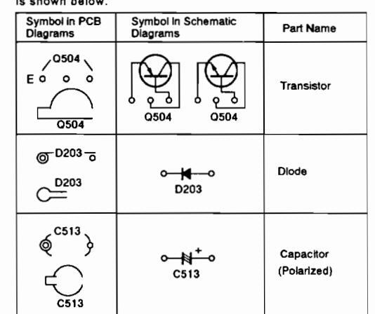
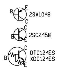
The transistor terminal marked with E or _ shows the emitter The diode terminal marked with © or _ shows cathode side The capacitor terminal marked with © or _ shows negative terminal.
The parts mounted on each PCB include all necessary parts for several destinations. For further information for respective destinations, be sure to check with the schematic diagram.
|
Symbol in PCB
Diagrams |
Symbol in Schematic
Diagrams |
Part Name |
|---|---|---|
|
000
BCE |
Transistor | |
|
Transistor
with resistor |
||
|
Field effect
transistor |
||
| (000)000 0 | Resistor array | |
| 000 | -[ | 3-terminal regulator |
SD-T50W1,SD-T43W1

5
L
6
Т
2
I
з
I
4
Г
21
SD-T50W1.SD-T43W1
F
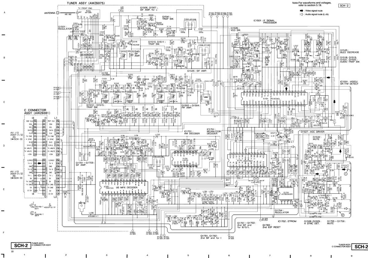
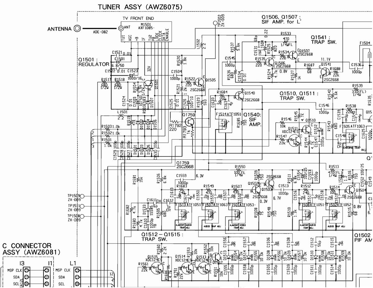
5.2 TUNER AND C CONNECTOR ASSEMBLIES
SD-T50W1,SD-T43W1
в
5.2 TUNER AND C CONNECTOR ASSEMBLIES

5

22
П
F
C CONNECTOR ASSY
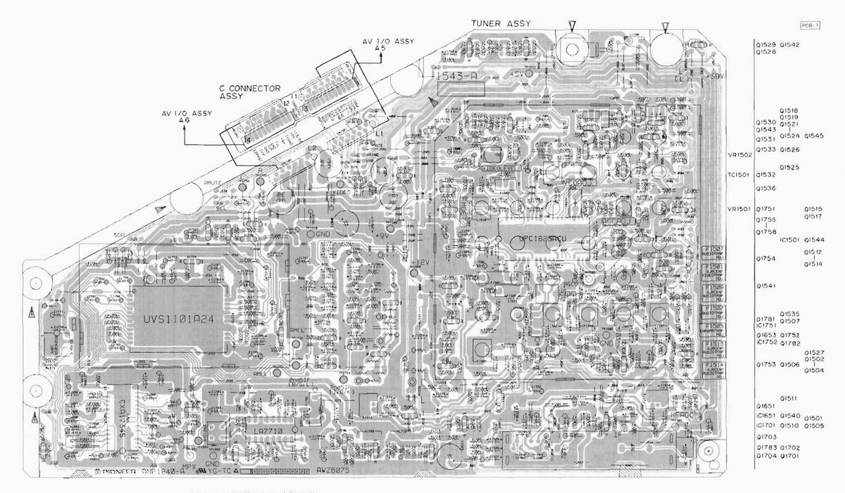
This diagram is viewed from the mounted parts side.
SD-T50W1,SD-T43W1

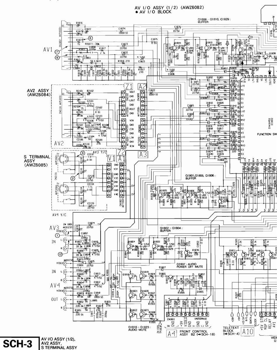
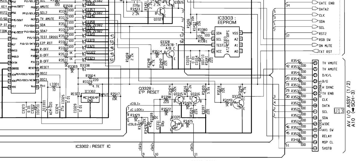
5.3 AV I/O (1/2), AV2 AND S TERMINAL ASSEMBLIES

1/2), SY, SSY SCH-3
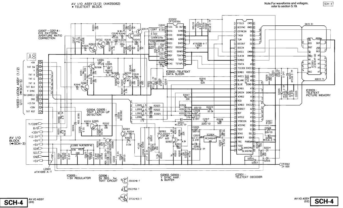


SCH-4
Note:For waveforms and voltages, refer to section 5.19.
2003 AMP.

• This diagram is viewed from the mounted parts side.
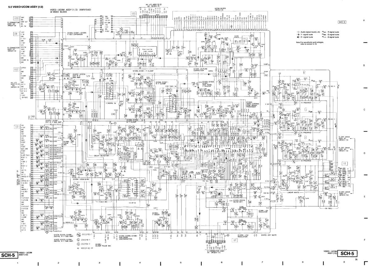

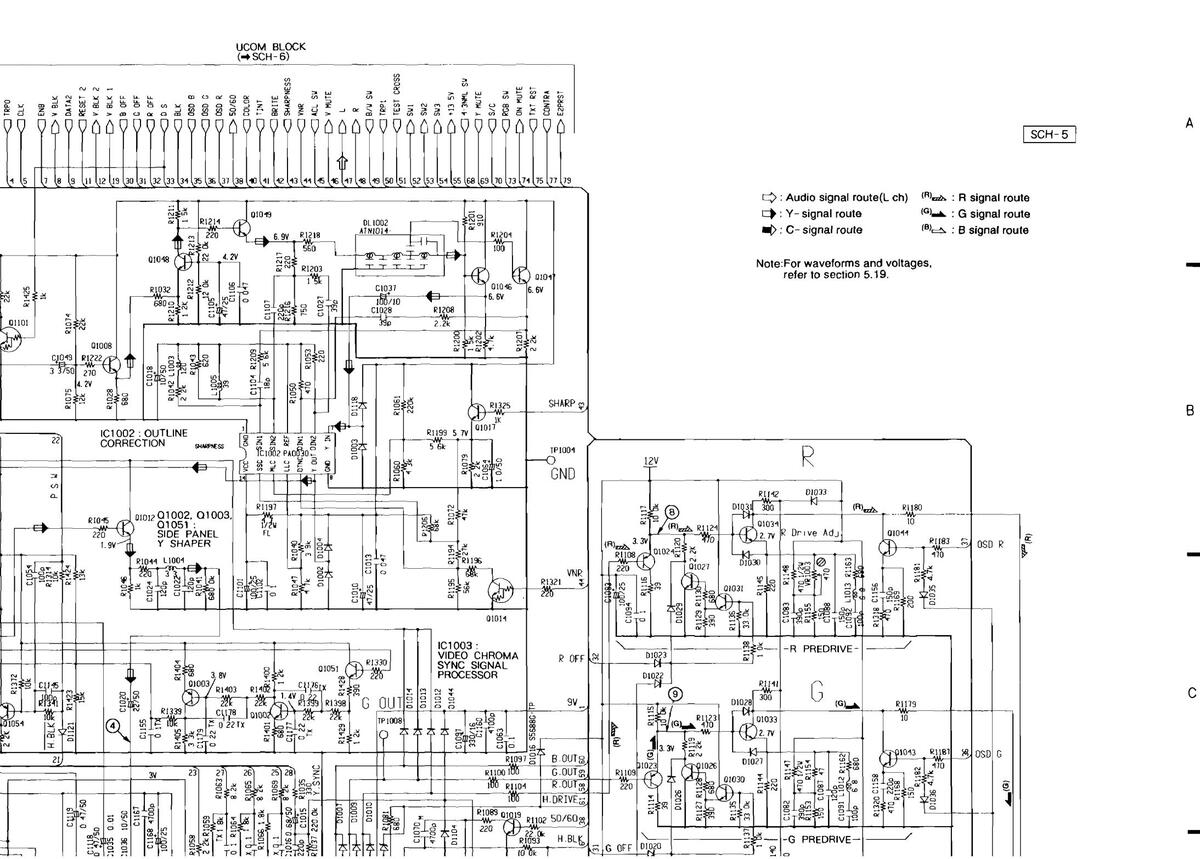
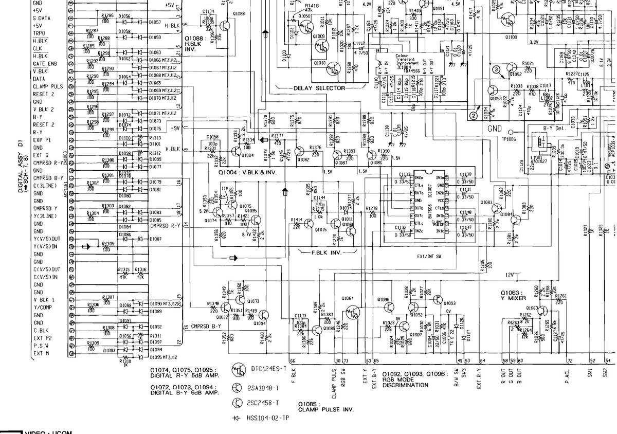
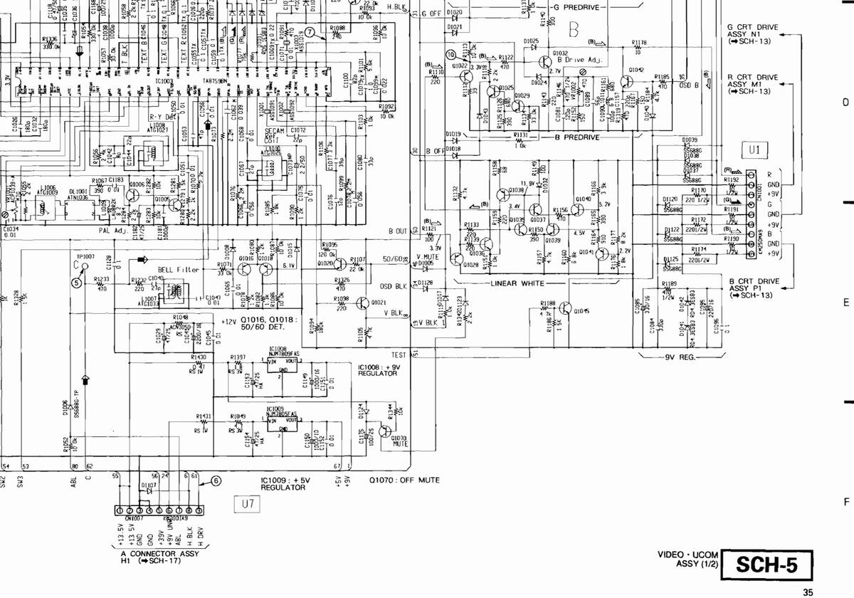
SCH-5 VIDEO · UCOM ASSY (1/2)
2
З
SD-T50W1.SD-T43W1
2
з
4
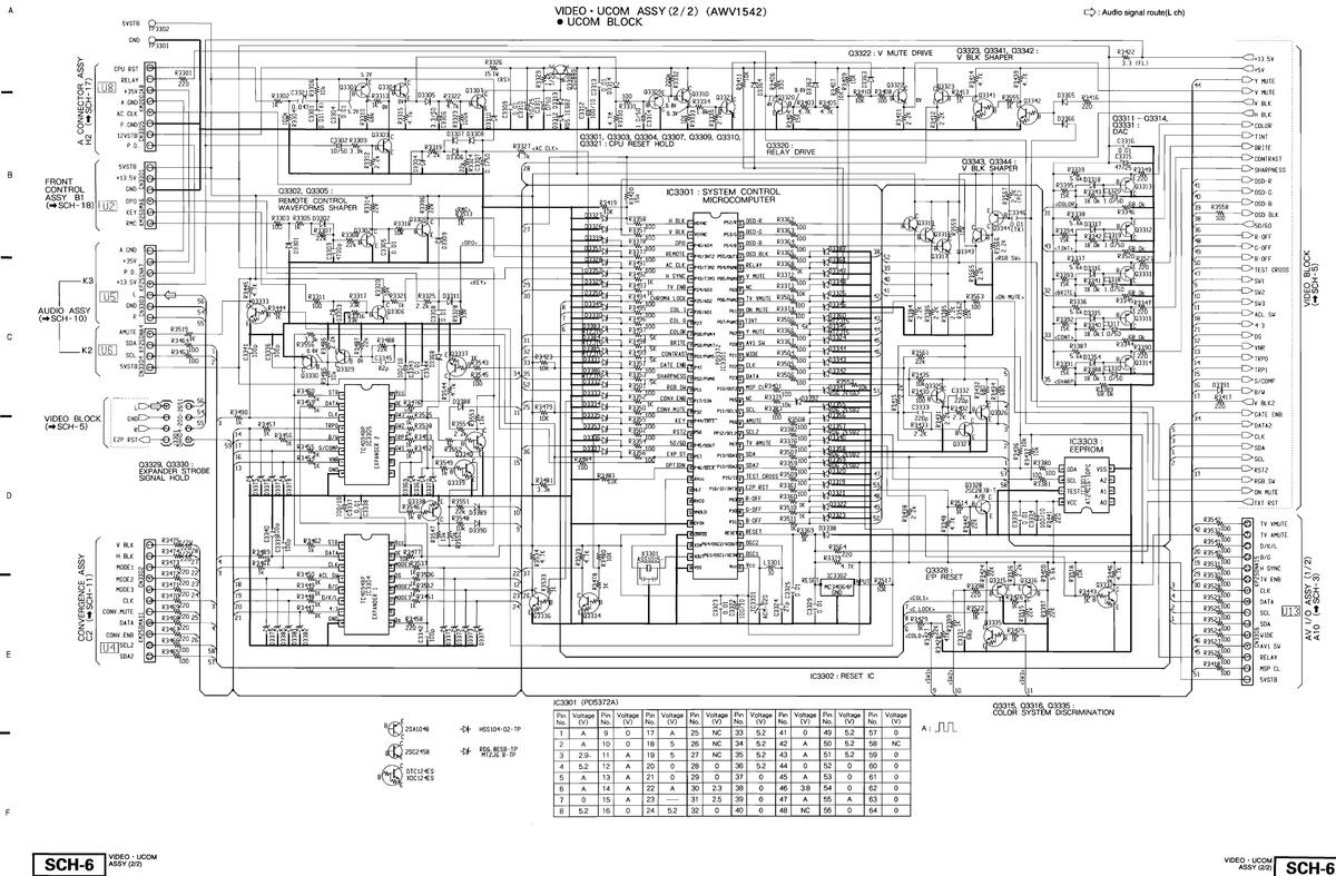
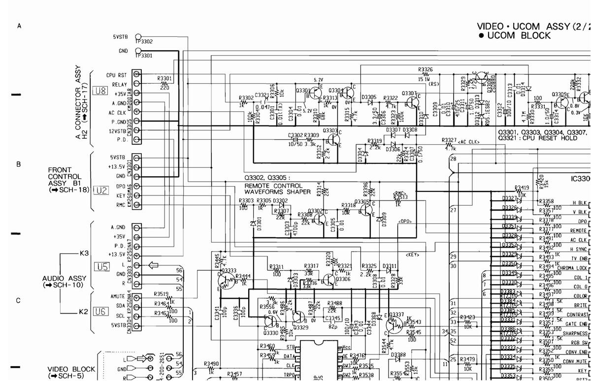
5.6 VIDEO·UCOM ASSY (2/2)
5
6
SCH-6
5.6 VIDEO·UCOM ASSY (2/2)

□ → : Audio signal route(L ch)


|
Pin
No. |
Voltage
(V) |
Pin
No. |
Voltage
(V) |
Pin
No. |
Voltage
(V) |
Pi
N |
|---|---|---|---|---|---|---|
| 1 | А | 9 | 0 | 17 | А | 2 |
| 2 | А | 10 | 0 | 18 | 5 | 2 |
| З | 2.9. | 11 | А | 19 | 5 | 2 |
| 4 | 5.2 | 12 | А | 20 | 0 | 2 |
| 5 | А | 13 | Α | 21 | 0 | 2 |
| 6 | А | 14 | Α | 22 | А | З |
| 7 | 0 | 15 | А | 23 | З | |
| 8 | 5.2 | 16 | 0 | 24 | 5.2 | 3 |
VIDEO · UCOM ASSY (2/2)
D
F
F
SCH-6
2
З
HSS104-02-TP
-DF RD6.8ESB-TP MTZJ6.8-TP
-N-
7
|
age
/) |
Pin
No. |
Voltage
(V) |
Pin
No. |
Voltage
(V) |
Pin
No. |
Voltage
(V) |
Pin
No. |
Voltage
(V) |
Pin
No. |
Voltage
(V) |
|
|---|---|---|---|---|---|---|---|---|---|---|---|
| ١ | 25 | NC | 33 | 5.2 | 41 | 0 | 49 | 5.2 | 57 | 0 | A : |
| 5 | 26 | NC | 34 | 5.2 | 42 | A | 50 | 5.2 | 58 | NC | |
| 5 | 27 | NC | 35 | 5.2 | 43 | А | 51 | 5.2 | 59 | 0 | |
| ) | 28 | 0 | 36 | 5.2 | 44 | 0 | 52 | 0 | 60 | 0 | |
| ) | 29 | 0 | 37 | 0 | 45 | Α | 53 | 0 | 61 | 0 | |
| ٩ | 30 | 2.3 | 38 | 0 | 46 | 3.8 | 54 | 0 | 62 | 0 | |
| - | 31 | 2.5 | 39 | 0 | 47 | Α | 55 | Α | 63 | 0 | |
| 2 | 32 | 0 | 40 | 0 | 48 | NC | 56 | 0 | 64 | 0 |
6
5
Q3315, Q3316, Q3335 : COLOR SYSTEM DISCRIMINATION
VIDEO · UCOM ASSY (2/2) SCH-6

SD-T50W1.SD-T43W1
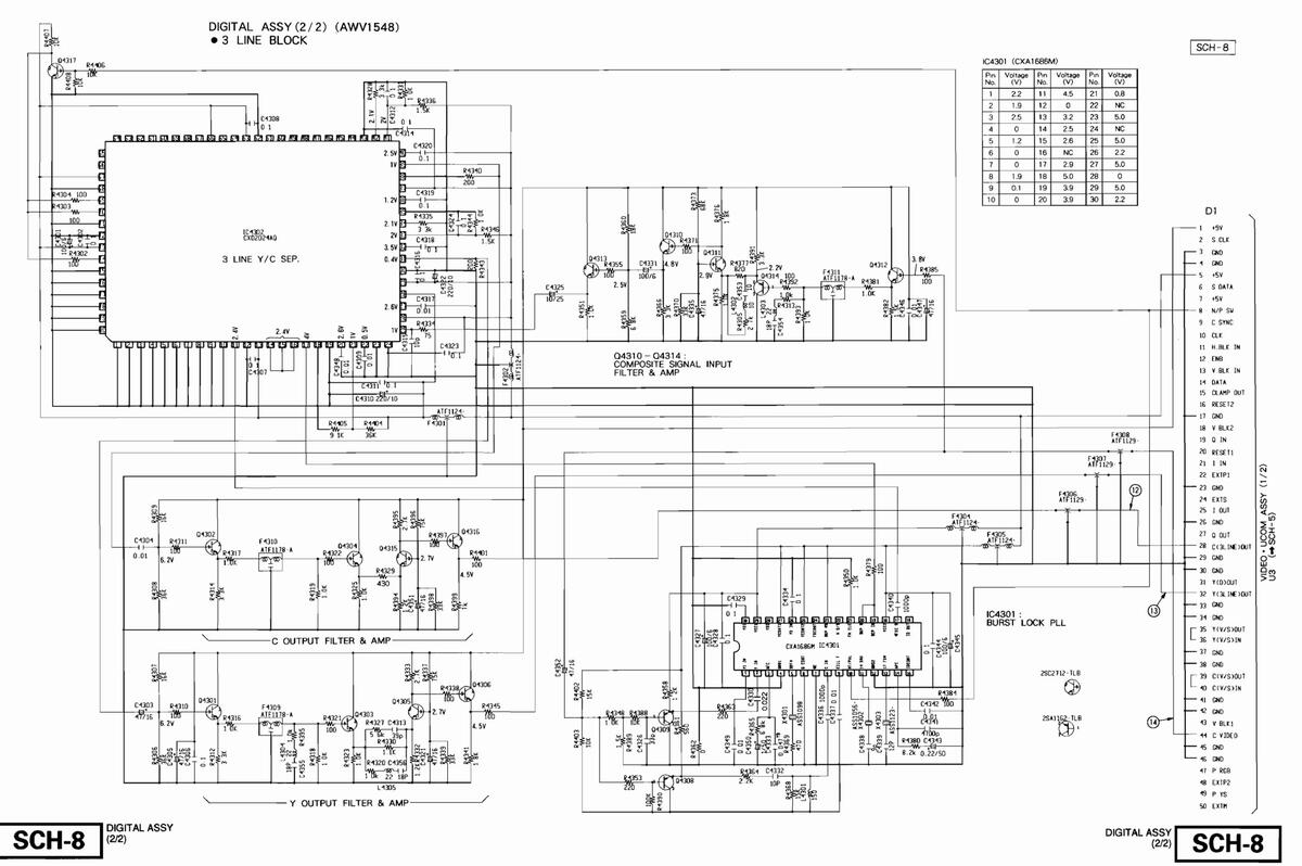
5.7 DIGITAL ASSY (1/2)
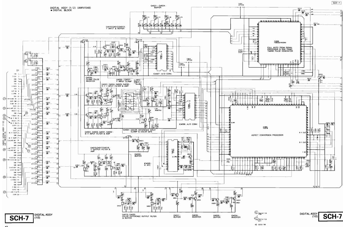
5.7 DIGITAL ASSY (1/2)


Waveformes of DIGITAL ASSY
• Input signal : Color bar
• Picture quality : Standard
• Range : DC range ( Unless otherwise noted )

SD-T50W1,SD-T43W1
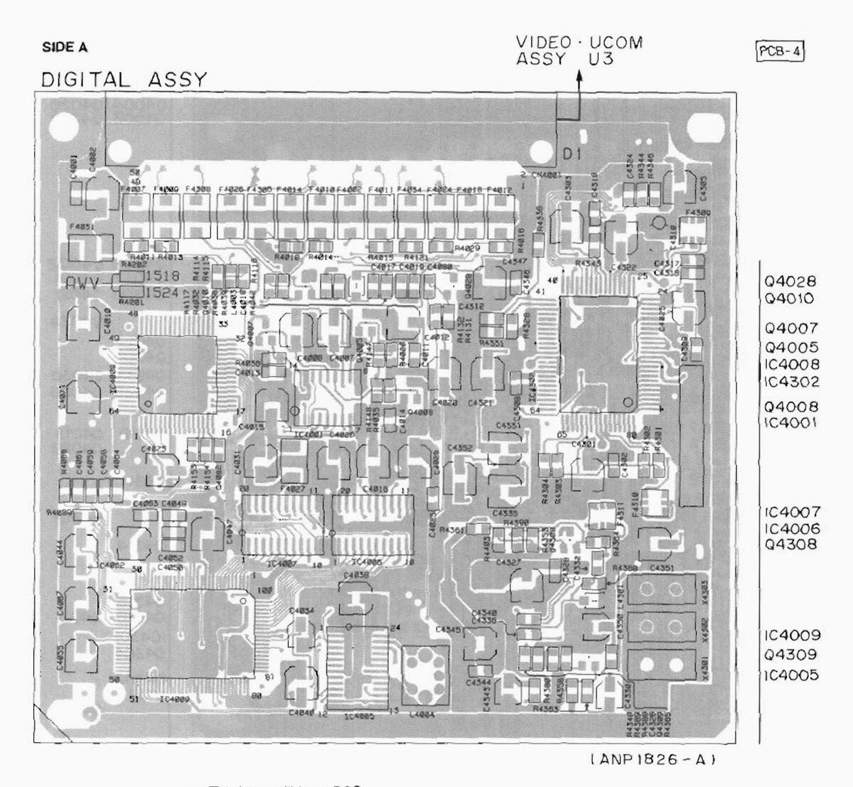
• This is a multi-layer PCB.
SIDE B
PCB - 4
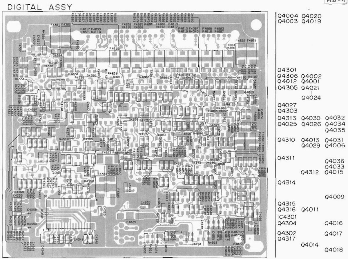
This is a multi-layer PCB.

SD-T50W1,SD-T43W1


5.9 Y/C AND D CONNECTOR ASSEMBLIES
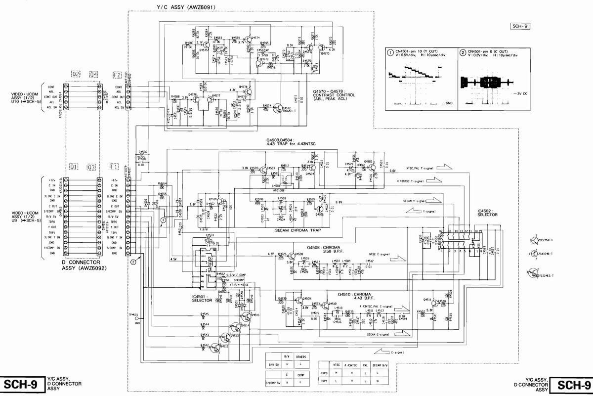
5.9 Y/C AND D CONNECTOR ASSEMBLIES
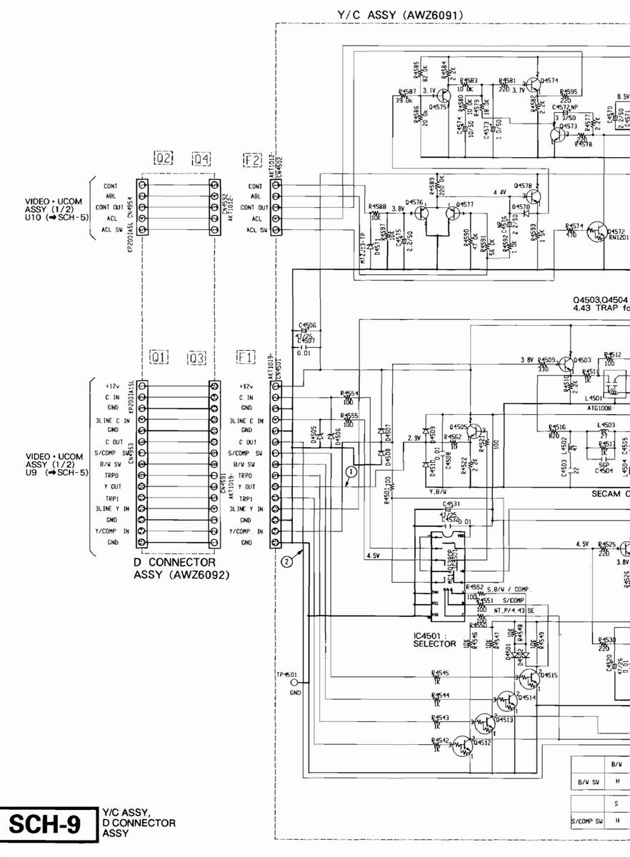


• This diagram is viewed from the mounted parts side.
SD-T50W1,SD-T43W1
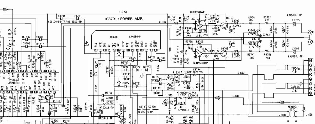
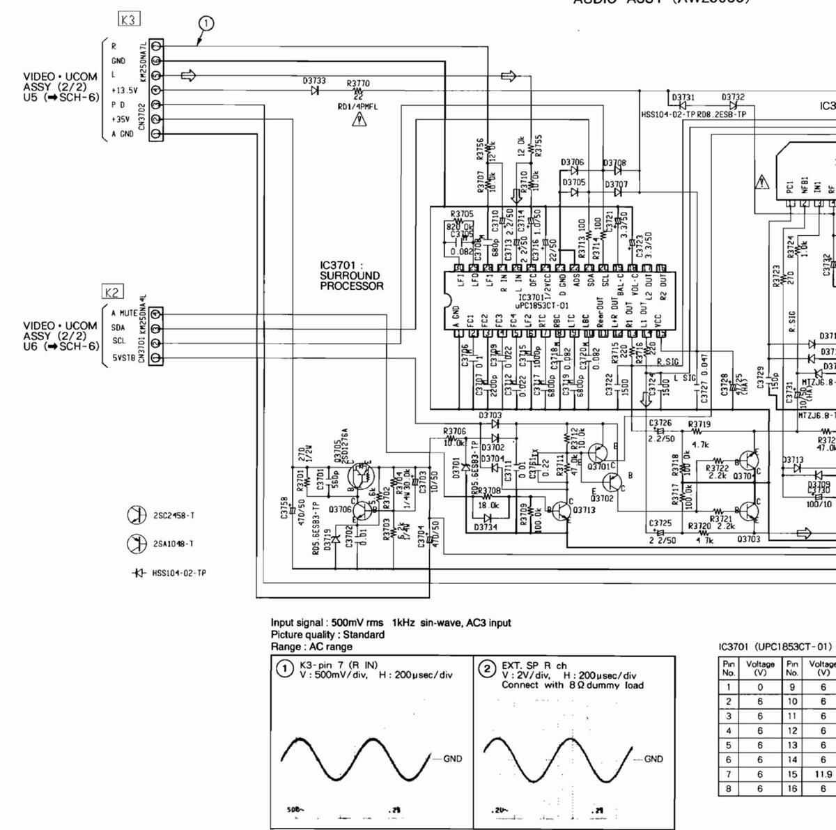
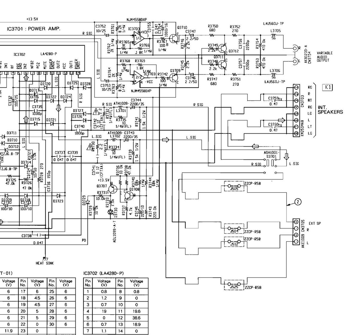
5.10 AUDIO ASSY

SD-T50W1,SD-T43W1
SCH-10
K1
INT. SPEAKERS
RO
RT
RG
¥E1009 €


J501 77CP-P58
_____R5Ł
J525 ZZCP-R58
PD
23.45 20.04
Voltage (V) 0.8
19.6 38.6 18.9 0

K3
GND
+13.5V 🗑
P D 20 00 +35V E 00 A CND 0
VIDEO • UCOM ASSY (2/2) U6 (→ SCH-6)
VIDEO • UCOM ASSY (2/2) U5 (⇒SCH-6)
D3733
R37
22 RD1/4PMFL
IC3701 : SURROUND PROCESSOF
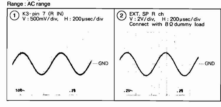
Input signal : 500mV rms 1kHz sin-wave, AC3 input Picture quality : Standard Range : AC range
| IC37 | 01 (UPC1 | 8530 | CT-01) | IC37 | 02 (LA428 | ||||
|---|---|---|---|---|---|---|---|---|---|
|
Pin
No. |
Voltage
(V) |
Pin
No. |
Voltage
(V) |
Pin
No. |
Voltage
(V) |
Pin
No. |
Voltage
(V) |
Pin
No. |
Voltage
(V) |
| 1 | 0 | 9 | 6 | 17 | 6 | 25 | 6 | 1 | 0.8 |
| 2 | 6 | 10 | 6 | 18 | 4.5 | 26 | 6 | 2 | 1.2 |
| 3 | 6 | 11 | 6 | 19 | 4.5 | 27 | 6 | З | 0.7 |
| 4 | 6 | 12 | 6 | 20 | 5 | 28 | 6 | 4 | 19 |
| 5 | 6 | 13 | 6 | 21 | 5 | 29 | 6 | 5 | 0 |
| 6 | 6 | 14 | 6 | 22 | 0 | 30 | 6 | 6 | 0.7 |
| 7 | 6 | 15 | 11.9 | 23 | 0 | 7 | 1.1 | ||
| 8 | 6 | 16 | 6 | 24 | 6 |
╞
HEAT SINK
SCH-10 AUDIO ASSY

SCH-10 AUDIO ASSY
SD-T50W1,SD-T43W1
SCH- 10
□ => : Audio signal route (L ch)

SD-T50W1,SD-T43W1
This diagram is viewed from the mounted parts side.
SD-T50W1.SD-T43W1
З
I
1
I
ł


____5
000012650-19
SD-T50W1,SD-T43W1
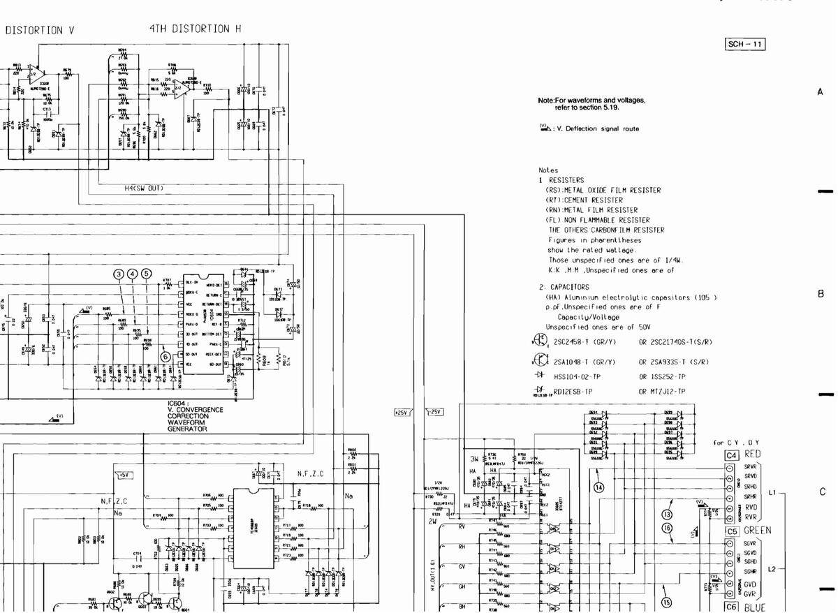
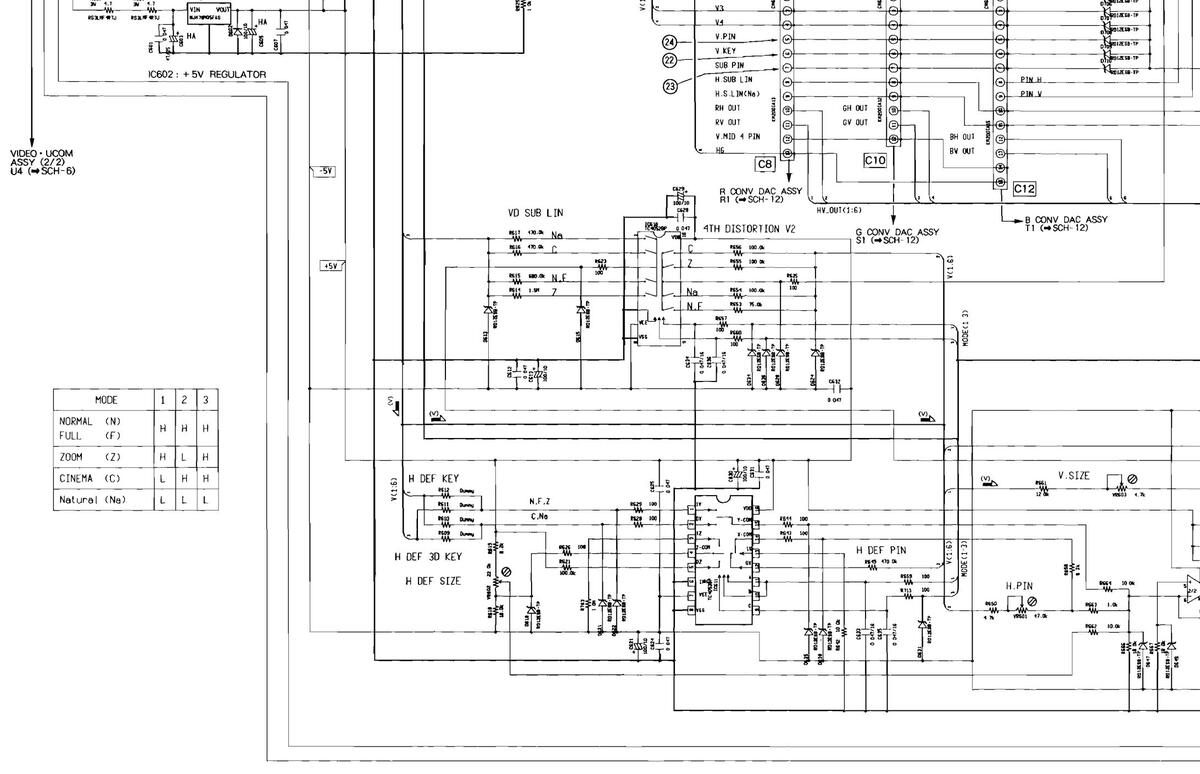
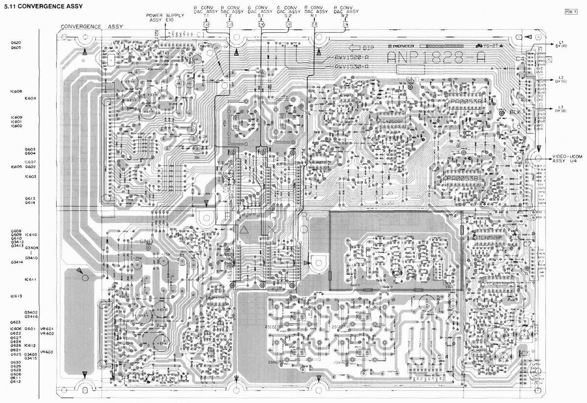
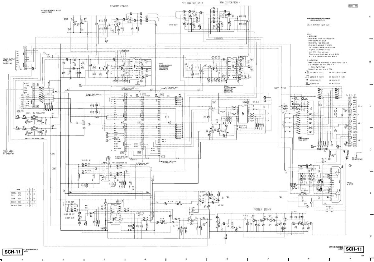
SCH-11 CONVERGENCE
ł
з
1
4
I
CONVERGENCE ASSY SCH-11
9
59

8
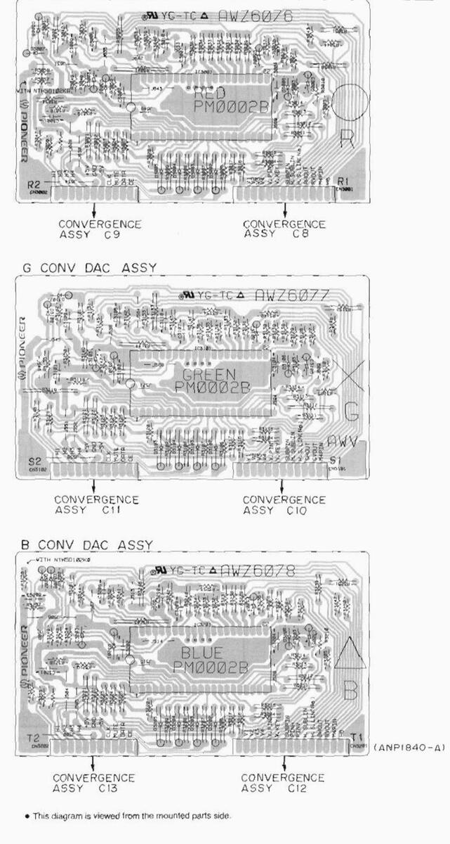
R CONV DAC ASSY
R. CONV DAC ASSY, G. CONV DAC ASSY, B. CONV DAC ASSY
.
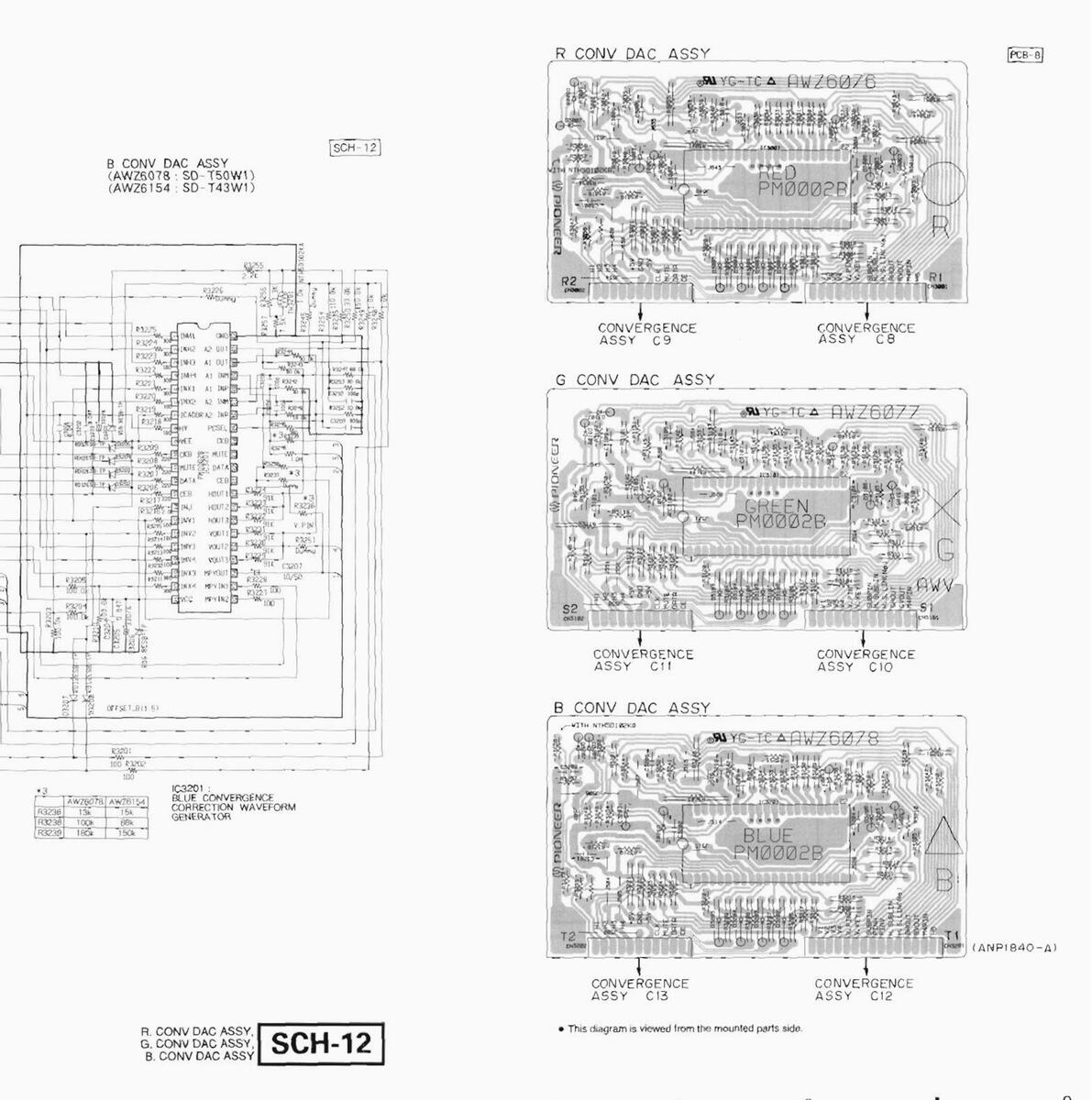
SCH-12 B. CONV DAC ASSY B. CONV DAC ASSY B. CONV DAC ASSY
PCB-8
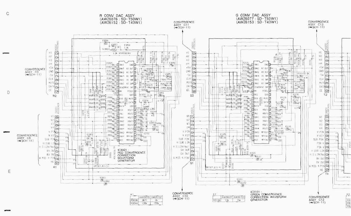
5.12 R CONV DAC, G CONV DAC AND B CONV DAC ASSEMBLIES

-
5.13 R. G AND B CRT DRIVE ASSEMBLIES
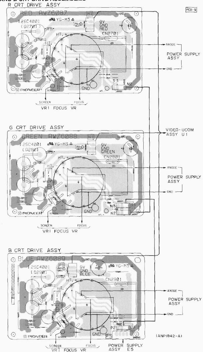

This diagram is viewed from the mounted parts side.
SD-T50W1.SD-T43W1
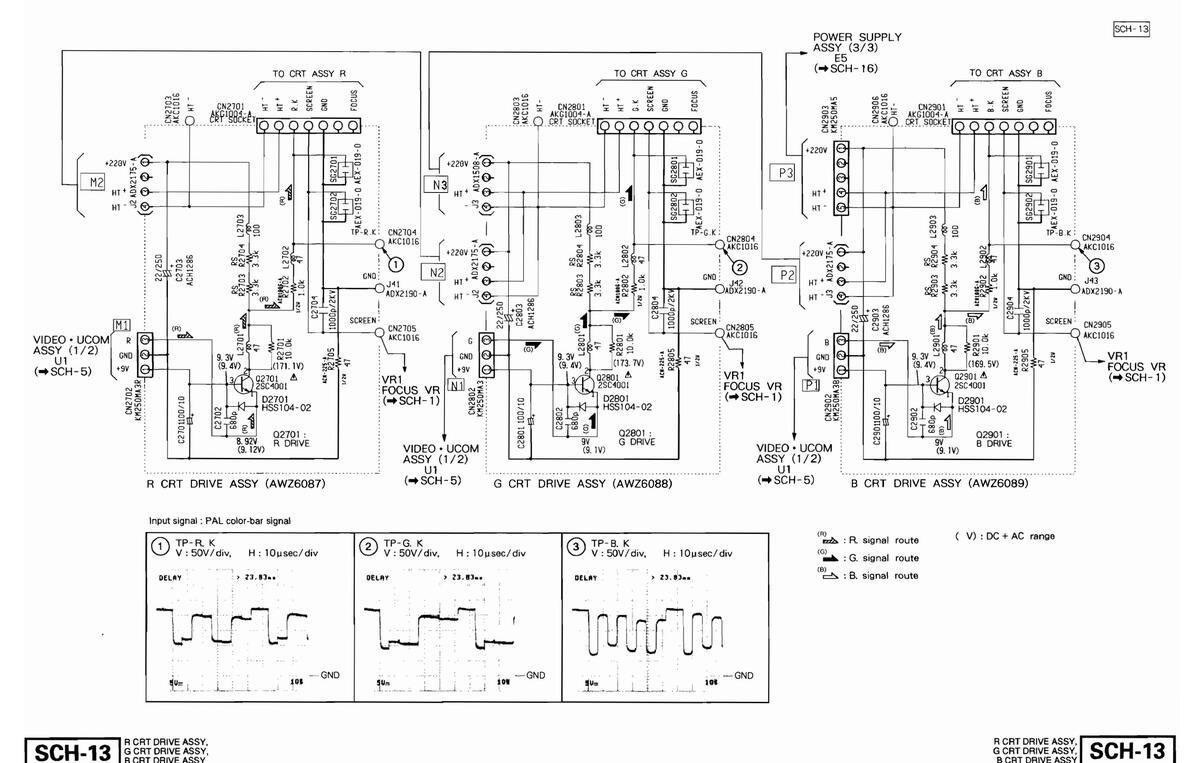

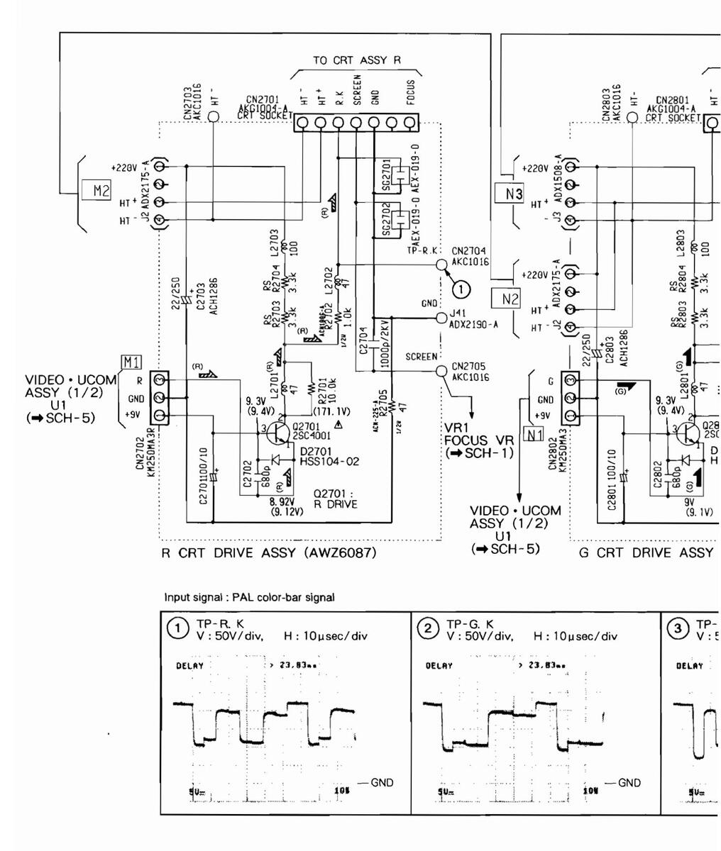
SCH-13 B CRT DRIVE ASSY, G CRT DRIVE ASSY, B CRT DRIVE ASSY
SD-T50W1,SD-T43W1


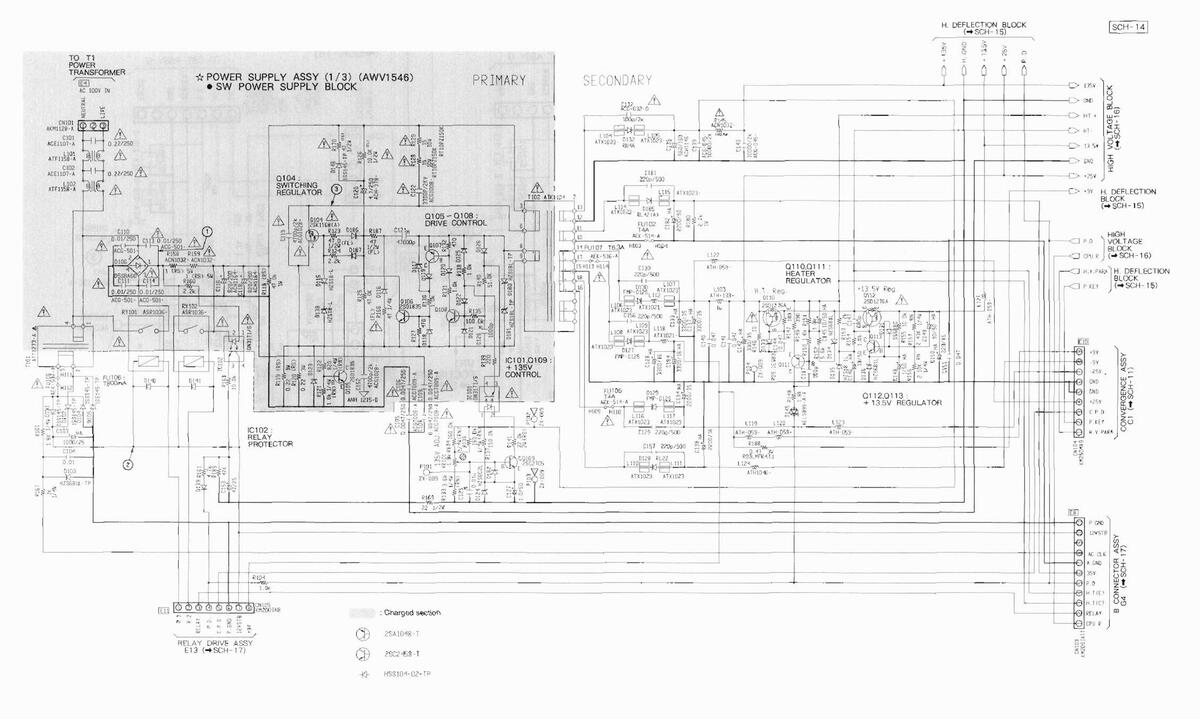
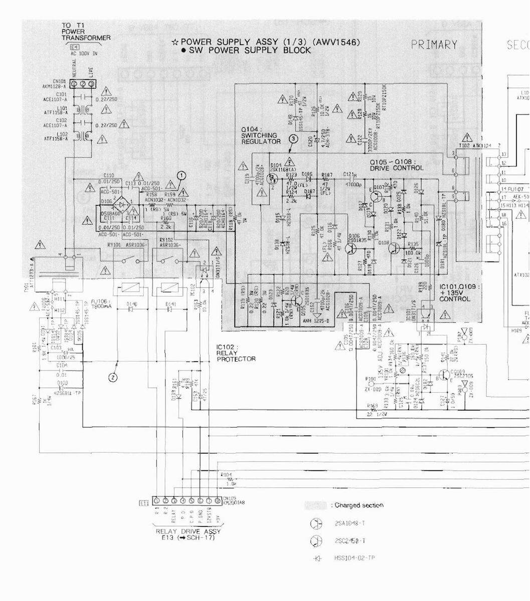
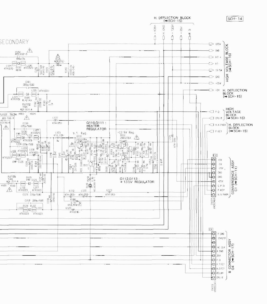
5.14 POWER SUPPLY ASSY (1/3)


SD-T50W1,SD-T43W1
5.14 POWER SUPPLY ASSY (1/3)


SD-T50W1.SD-T43W1
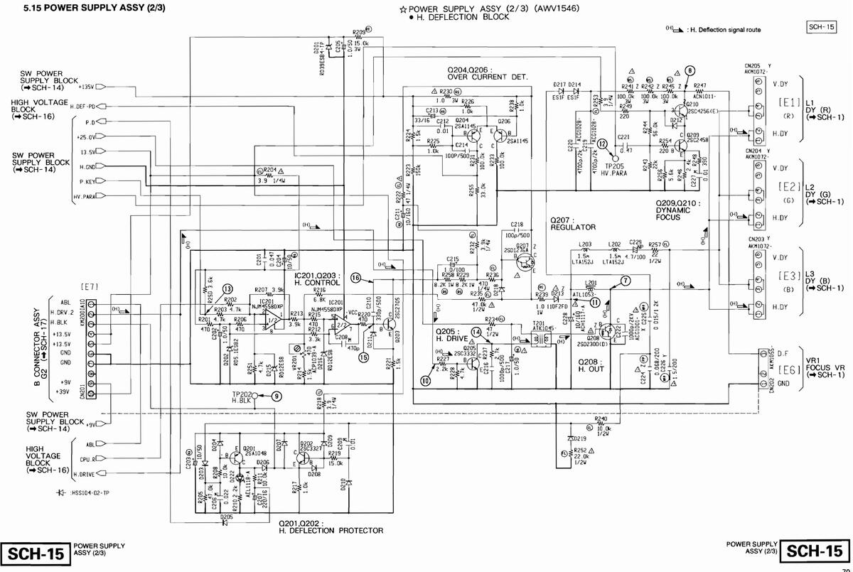


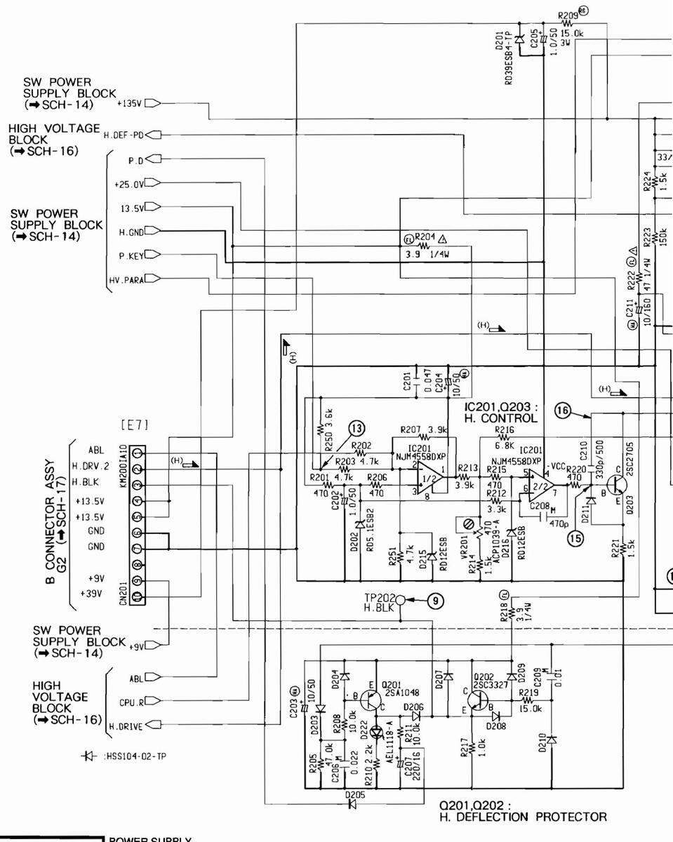
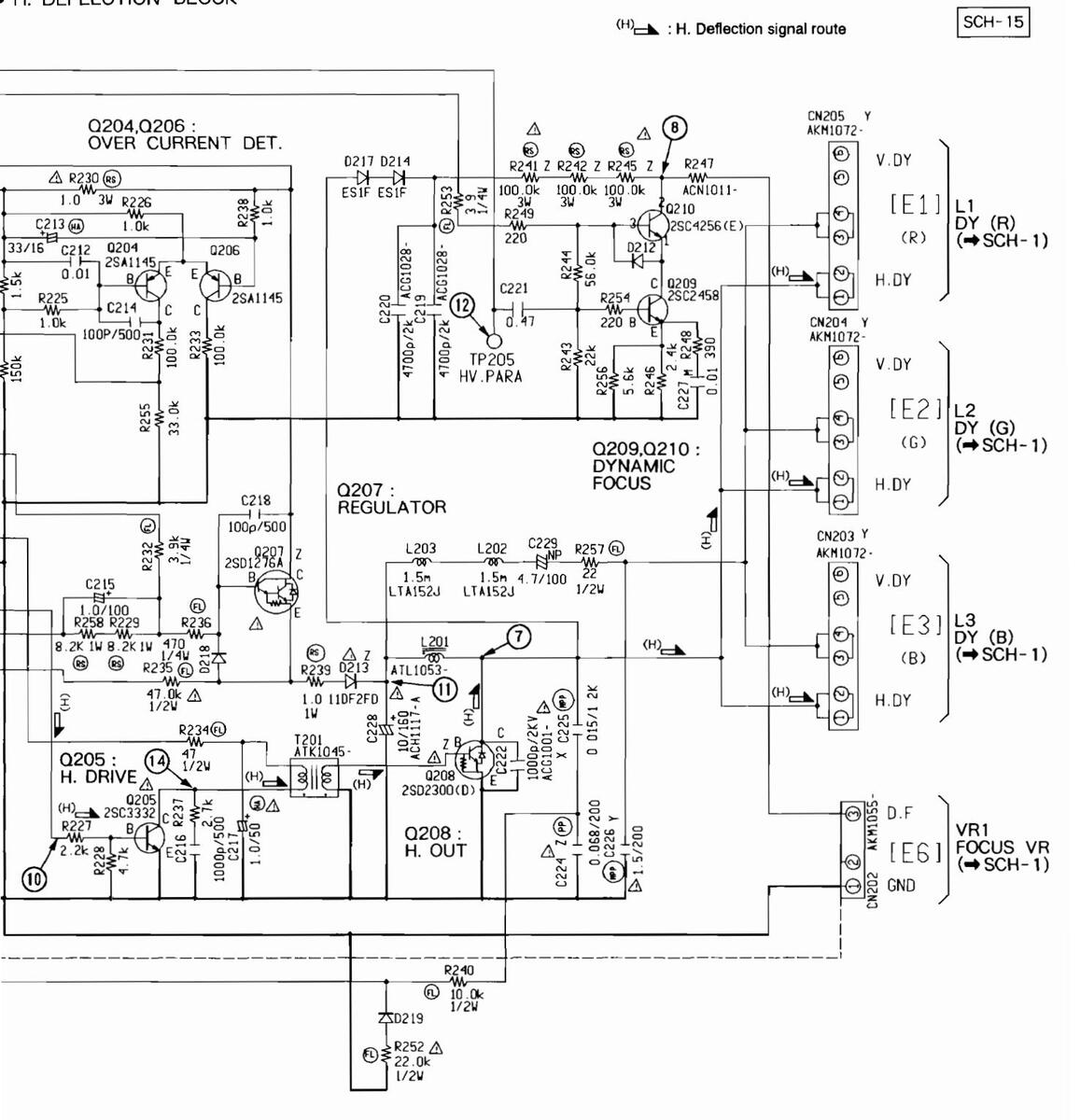
SCH-15 POWER SUPPLY ASSY (2/3)
POWER SUPPLY ASSY (2/3) (AWV1546) H. DEFLECTION BLOCK

SD-T50W1.SD-T43W1
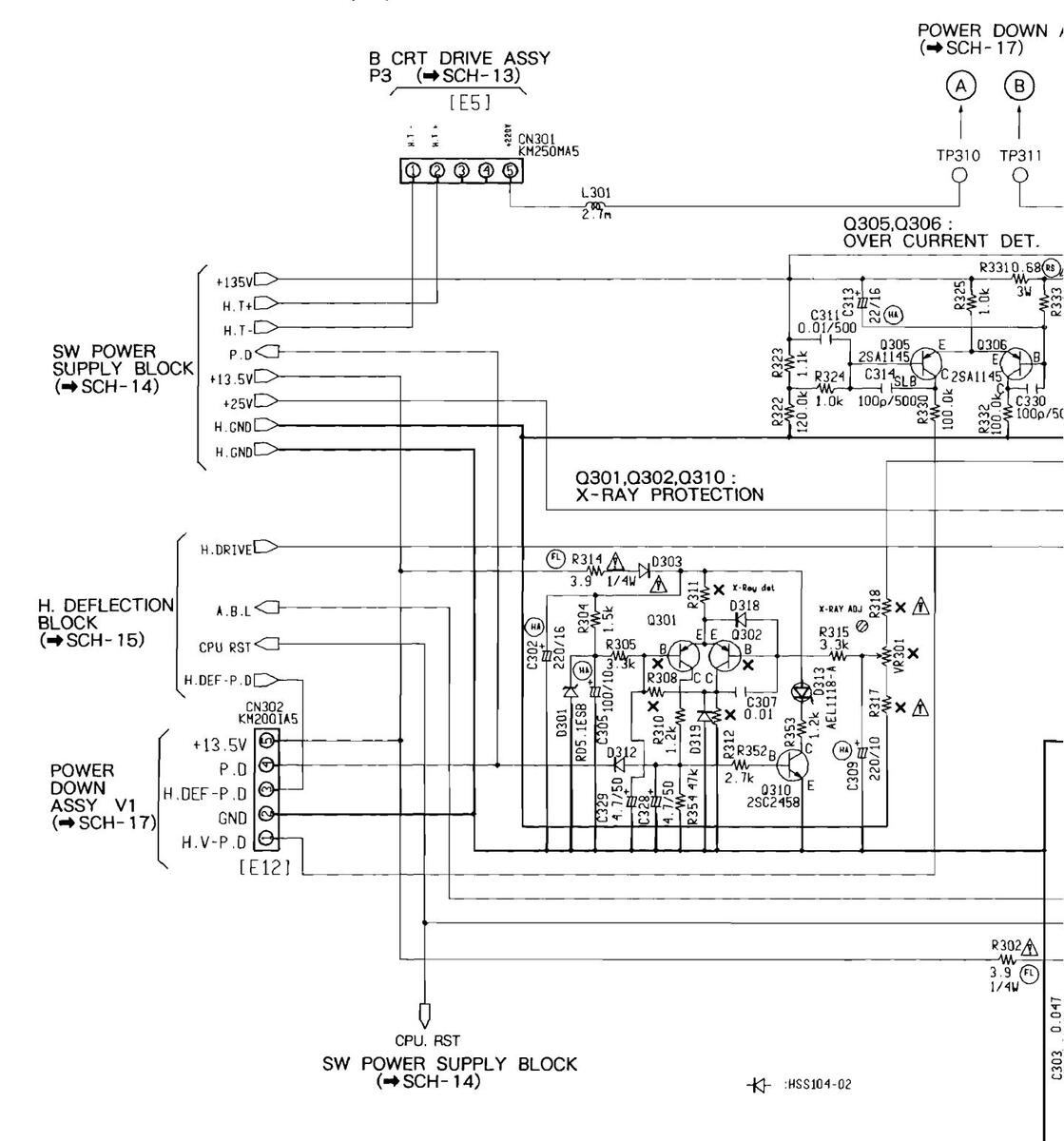
5.16 POWER SUPPLY ASSY (3/3)


5.16 POWER SUPPLY ASSY (3/3)

N ASSY
☆ POWER SUPPLY ASSY (3/3) (AWV1546) ● HIGH VOLTAGE BLOCK
11
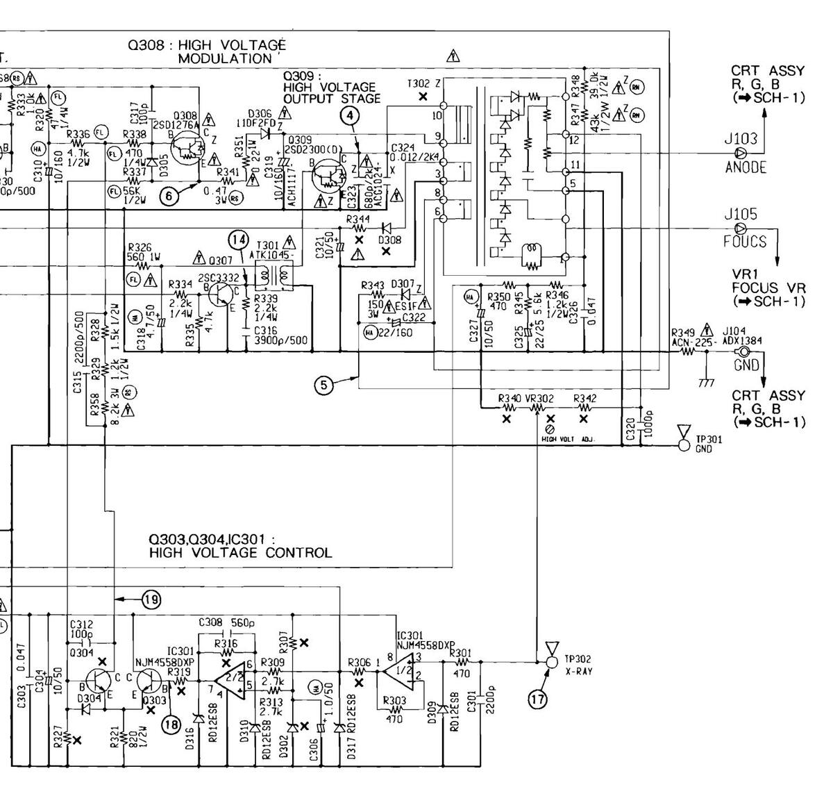
POWER SUPPLY ASSY (3/3) SCH-16
SCH-16

SD-T50W1,SD-T43W1
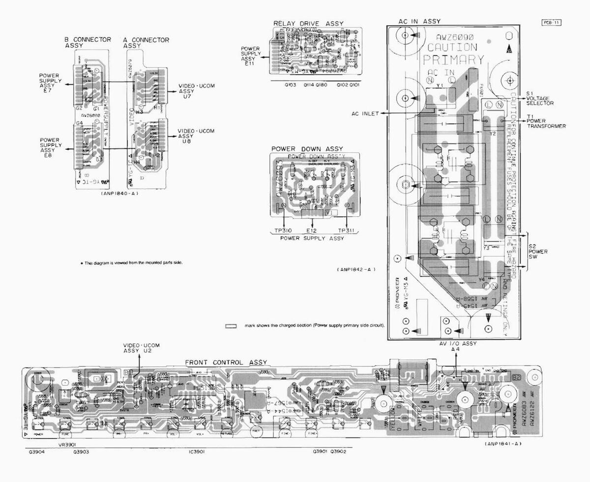
5.17 AC IN, POWER DOWN, RELAY DRIVE, A CONNECTOR AND B CONNECTOR ASSEMBLIES
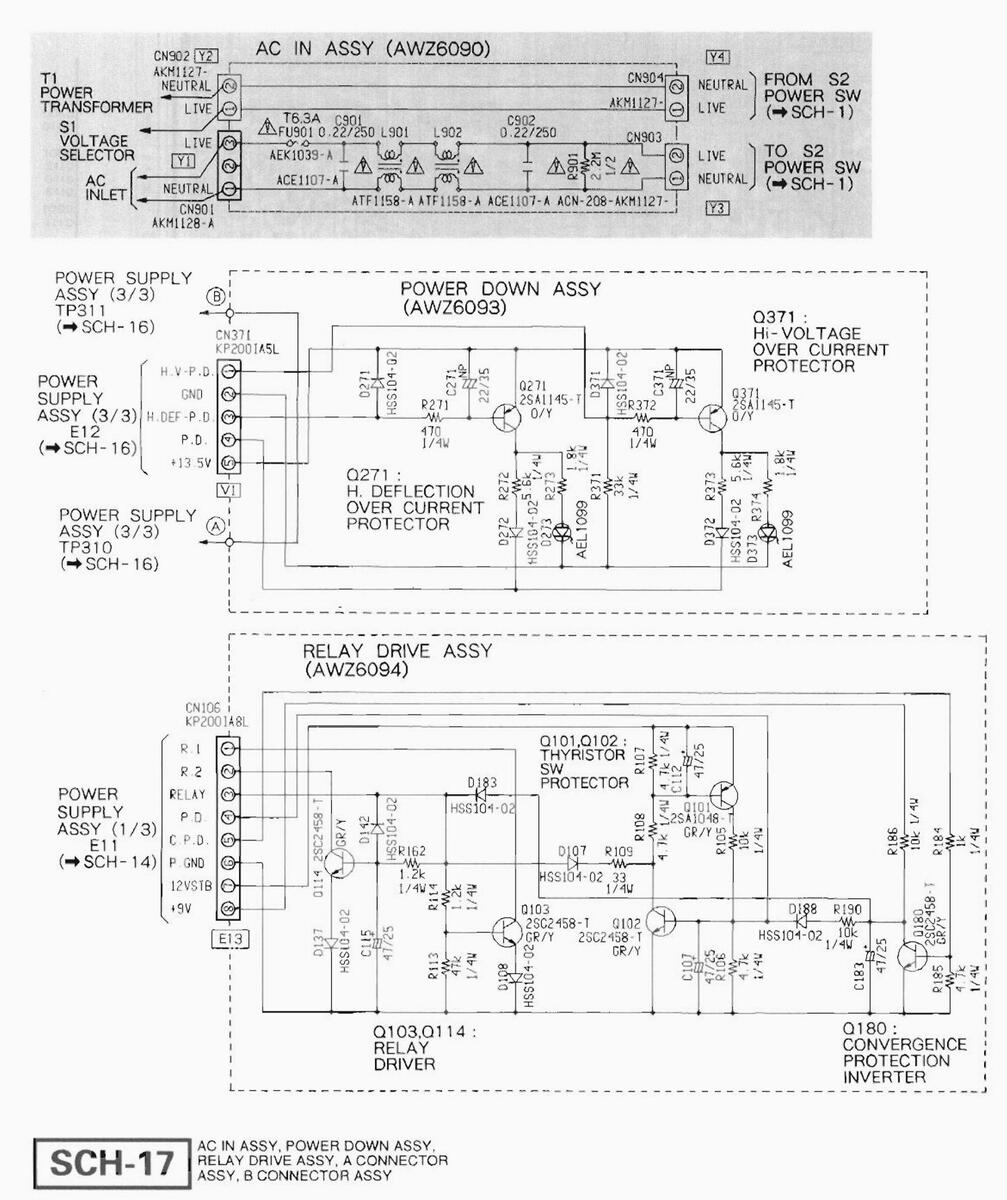
Charged section
SCH-17

SD-T50W1,SD-T43W1
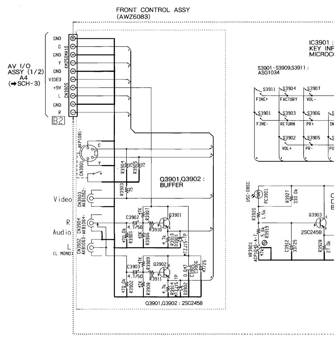
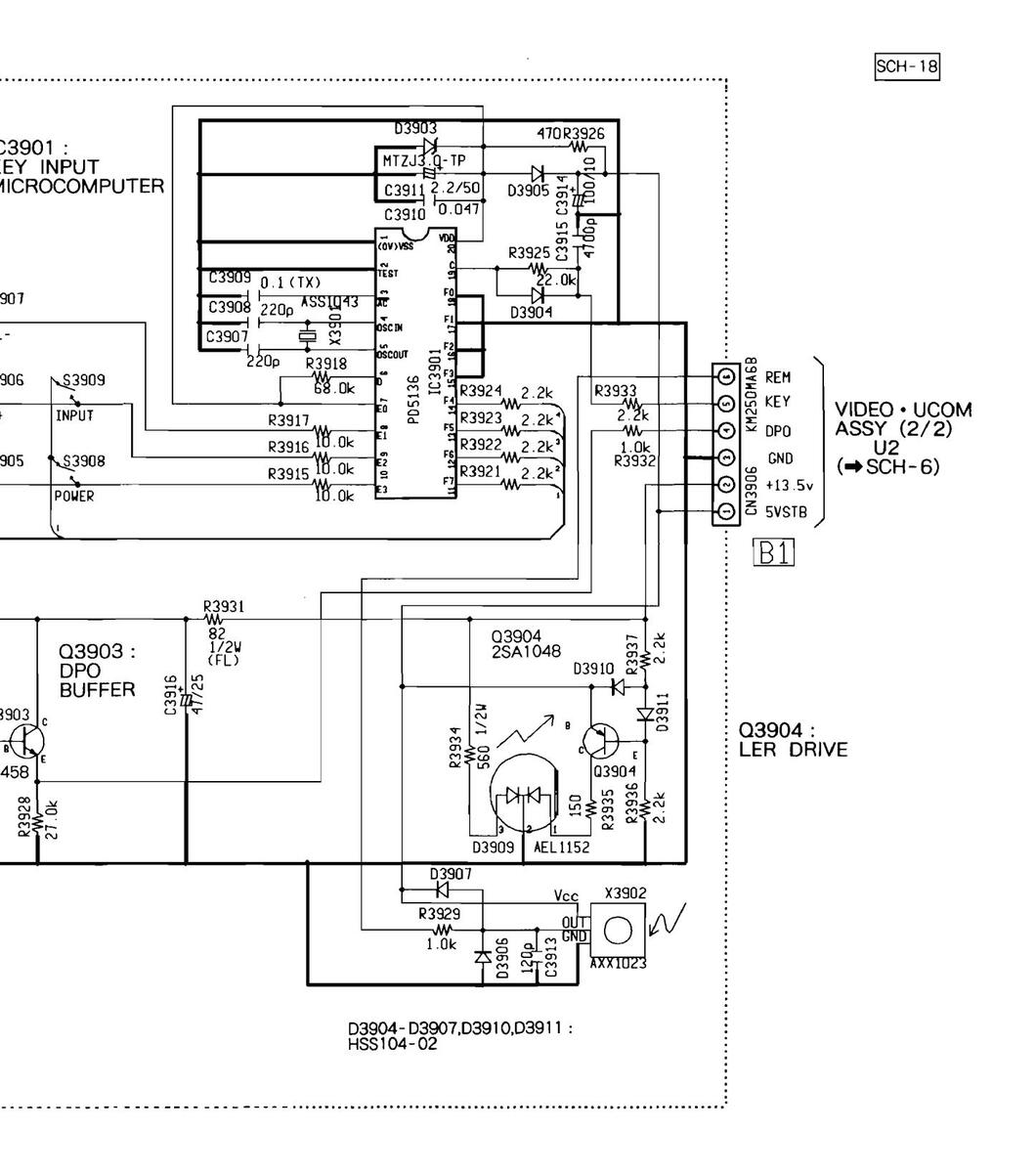
5.18 FRONT CONTROL ASSY

SCH-18 FRONT CONTROL ASSY
FRONT CONTROL ASSY SCH-18
5.18 FRONT CONTROL ASSY
FRONT CONTROL ASS
SCH-18
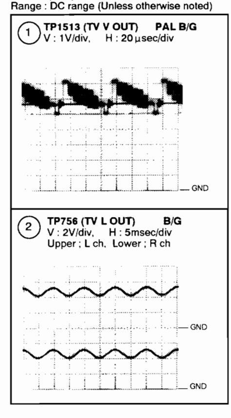
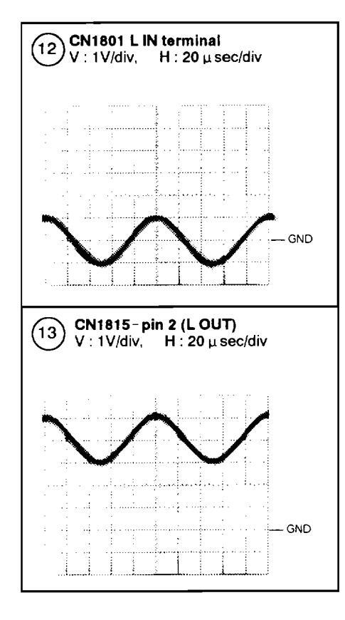
5.19 WAVEFORMS AND VOLTAGES
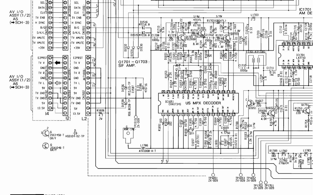
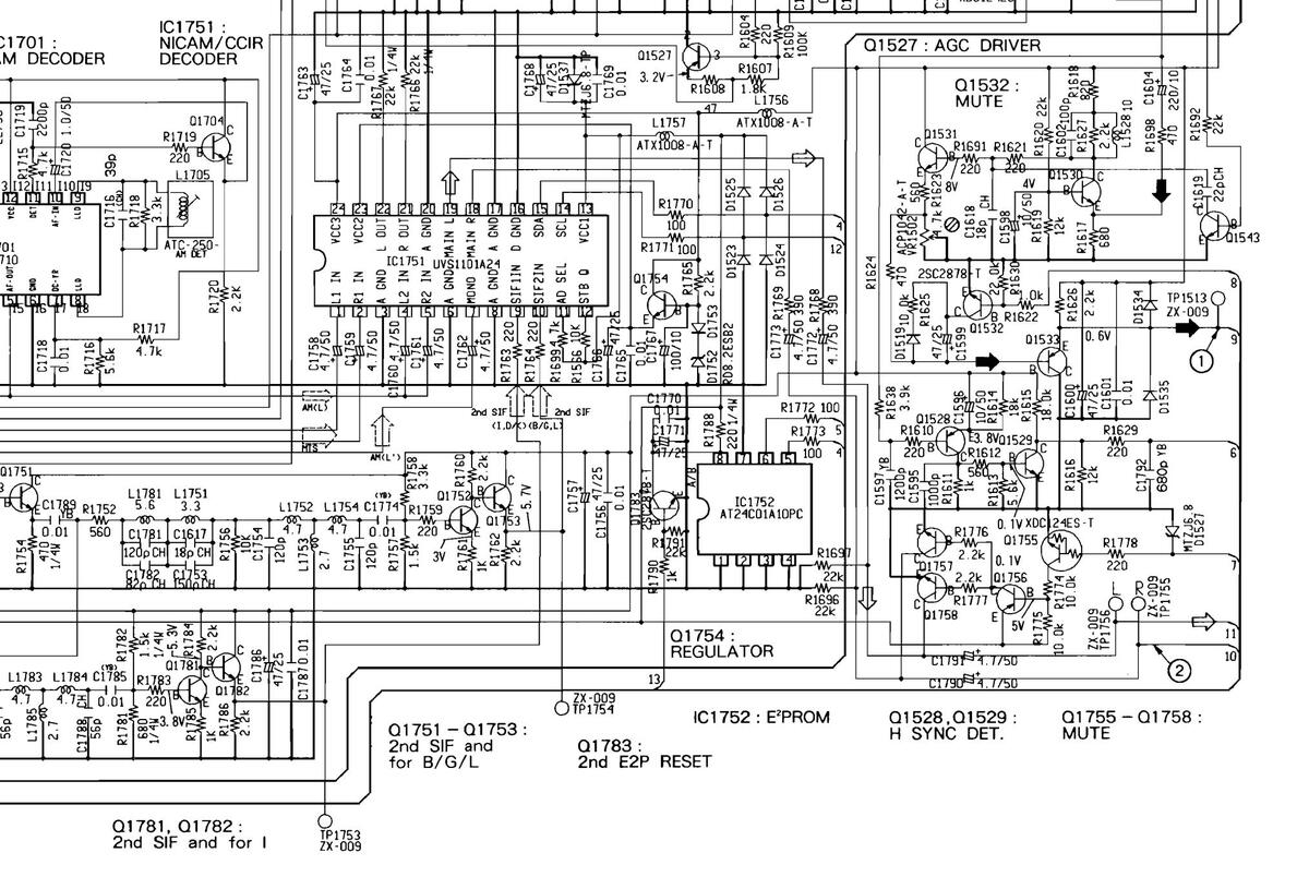
SCH-2 TUNER ASSY
Input Signal : Color-bar , AV3 input Picture quality : Standard Range : DC range (Unless otherwise noted)
| System | \ | /oltage (V | ) | ||
|---|---|---|---|---|---|
| Measuring Point | м | B/G | 1 | D/K/L | Ľ |
| D1513 Anode | 6.1 | 0.1 | 4.0 | 4.2 | 4.0 |
| D1514 Anode | 0 | 3.3 | 0 | 0 | 0 |
| D1508 Anode | 0 | 0.1 | 0 | 4.2 | 0 |
| D1509 Anode | 0 | 3.3 | 0 | 0 | 0 |
| D1510 Anode | 6.1 | 0.1 | 4.0 | 4.2 | 4.0 |
| D1511 Anode | 0 | 3.3 | 0 | 0 | 0 |
| D1511 Cathode | 8.4 | 2.6 | 3.3 | 3.6 | 3.3 |
| D1533 Anode | 5.0 | 3.6 | 0.1 | 3.9 | 0.2 |
| D1533 Cathode | 4.3 | 3.0 | 2.9 | 3.3 | 2.9 |
| D1512 Anode | 2.8 | 0.2 | 1.6 | 1.6 | 0.2 |
| D1512 Cathode | 2.1 | 8.3 | 8.3 | 8.3 | 8.3 |
IC1501 (UPC1823ACU)
|
Pin
No. |
Voltage
(V) |
Pin
No. |
Voltage
(V) |
Pin
No. |
Voltage
(V) |
Pin
No. |
Voltage
(V) |
|---|---|---|---|---|---|---|---|
| 1 | 0 | 12 | 5.9 | 23 | 0.2 to 5.1 | 34 | 7.6 |
| 2 | 4.6 | 13 | 5.9 | 24 | 0 | 35 | 7.6 |
| 3 | 8.9 | 14 | 8.9 | 25 | 5.4 | 36 | 0 |
| 4 | 8.9 | 15 | 8.0 | 26 | 8.6 | 37 | 4.9 |
| 5 |
L': 2.9
other: 0.8 |
16 |
M : 0
other : 2.6 |
27 | 6.7 | 38 | 4.8 |
| 6 | 0 | 17 |
L':0
other:2.2 |
28 | 3.4 | 39 | 4.8 |
| 7 |
L' : 0.8
other : 2.9 |
18 | 8.9 | 29 | 3.4 | 40 | 4.1 |
| 8 | 8.9 | 19 | 1.1 | 30 | 4.3 | 41 | 5.2 |
| 9 | 2.0 | 20 | 7.6 | 31 | 3.5 | 42 | 2.9 |
| 10 | 2.0 | 21 | 0 | 32 | 4.5 | ||
| 11 | 0 | 22 | 0.2 to 5.1 | 33 | 8.9 |
IC1651 (CXA1734S)
|
Pin
No. |
Voltage
(V) |
Pin
No. |
Voltage
(V) |
|---|---|---|---|
| 1 | 16 | 4.0 | |
| 2 | 17 | 0 | |
| 3 | 0 | 18 | 4.0 |
| 4 | 0 | 19 | 4.0 |
| 5 | 1.3 | 20 | 4.0 |
| 6 | 1.3 | 21 | 4.0 |
| 7 | 4.0 | 22 | 1.7 |
| 8 | 4.2 | 23 | 4.0 |
| 9 | 3.4 | 24 | 4.1 |
| 10 | 5.3 | 25 | 3.9 |
| 11 | 3.9 | 26 | 1.7 |
| 12 | 3.2 | 27 | 1.3 |
| 13 | 4.1 | 28 | 4.1 |
| 14 | 4.0 | 29 | 4.1 |
| 15 | 9.1 | 30 | NC |
IC1701 (LA7710)
|
Pin
No. |
Voltage
(V) |
Pin
No. |
Voltage
(V) |
|---|---|---|---|
| 1 | 4.4 | 9 | 9.0 |
| 2 | 4.4 | 10 | 2.8 |
| З | 6.3 | 11 | 6.2 |
| 4 | NC | 12 | 12.1 |
| 5 | 6.4 | 13 | 2.9 |
| 6 | 0 | 14 | 5.8 |
| 7 | 6.4 | 15 | 4.4 |
| 8 | 8.9 | 16 | 4.4 |
IC1751 (UVS1101A24)
|
Pin
No. |
Voltage
(V) |
Pin
No. |
Voltage
(V) |
| 1 | 3.8 | 13 | 4.8 |
| 2 | 3.8 | 14 | |
| З | 0 | 15 | |
| 4 | 3.8 | 16 | 0 |
| 5 | 3.8 | 17 | 0 |
| 6 | 0 | 18 | 6.0 |
| 7 | 3.8 | 19 | 6.0 |
| 8 | 0 | 20 | 0 |
| 9 | 4.6 | 21 | 3.7 |
| 10 | 4.6 | 22 | 3.7 |
| 11 | 4.8 | 23 | 7.9 |
| 12 | 4.8 | 24 | 12.1 |
SCH-3 AV I/O (1/2), AV2 AND S TERMINAL ASSEMBLIES
Input Signal : Color-bar , AV3 input Picture quality : Standard Range : DC range (Unless otherwise noted)

IC1802 (CXA1845Q)
|
Pin
No. |
Voltage
(V) |
Pin
No. |
Voltage
(V) |
Pin
No. |
Voltage
(V) |
Pin
No. |
Voltage
(V) |
|---|---|---|---|---|---|---|---|
| 1 | 4.5 | 17 | 4.5 | 33 | 0 | 49 | 4.5 |
| 2 | 4.6 | 18 | NC | 34 | 4.6 | 50 | 4.6 |
| З | 4.5 | 19 | 4.5 | 35 | 4.5 | 51 | NC |
| 4 | 4.6 | 20 | 4.6 | 36 | 4.6 | 52 | 4.6 |
| 5 | 4.5 | 21 | 4.5 | 37 | 0 | 53 | 4.5 |
| 6 | NC | 22 | 4.6 | 38 | NC | 54 | 4.6 |
| 7 | 4.5 | 23 | 4.5 | 39 | 9.0 | 55 | NC |
| 8 | 4.6 | 24 | NC | 40 | NC | 56 | 4.5 |
| 9 | 4.5 | 25 | 4.5 | 41 | 4.6 | 57 | 0 |
| 10 | 4.6 | 26 | 4.6 | 42 | 4.5 | 58 | 4.5 |
| 11 | 4.5 | 27 | 4.5 | 43 | 4.6 | 59 | 0 |
| 12 | NC | 28 | 4.6 | 44 | NC | 60 | 0 |
| 13 | 4.5 | 29 | 4.5 | 45 | NC | 61 | 0 |
| 14 | 4.6 | 30 | NC | 46 | 0 | 62 | 4.6 |
| 15 | 4.5 | 31 | 0⁄5 | 47 | NC | 63 | 4.5 |
| 16 | 4.6 | 32 | 0⁄5 | 48 | NC | 64 | 4.6 |

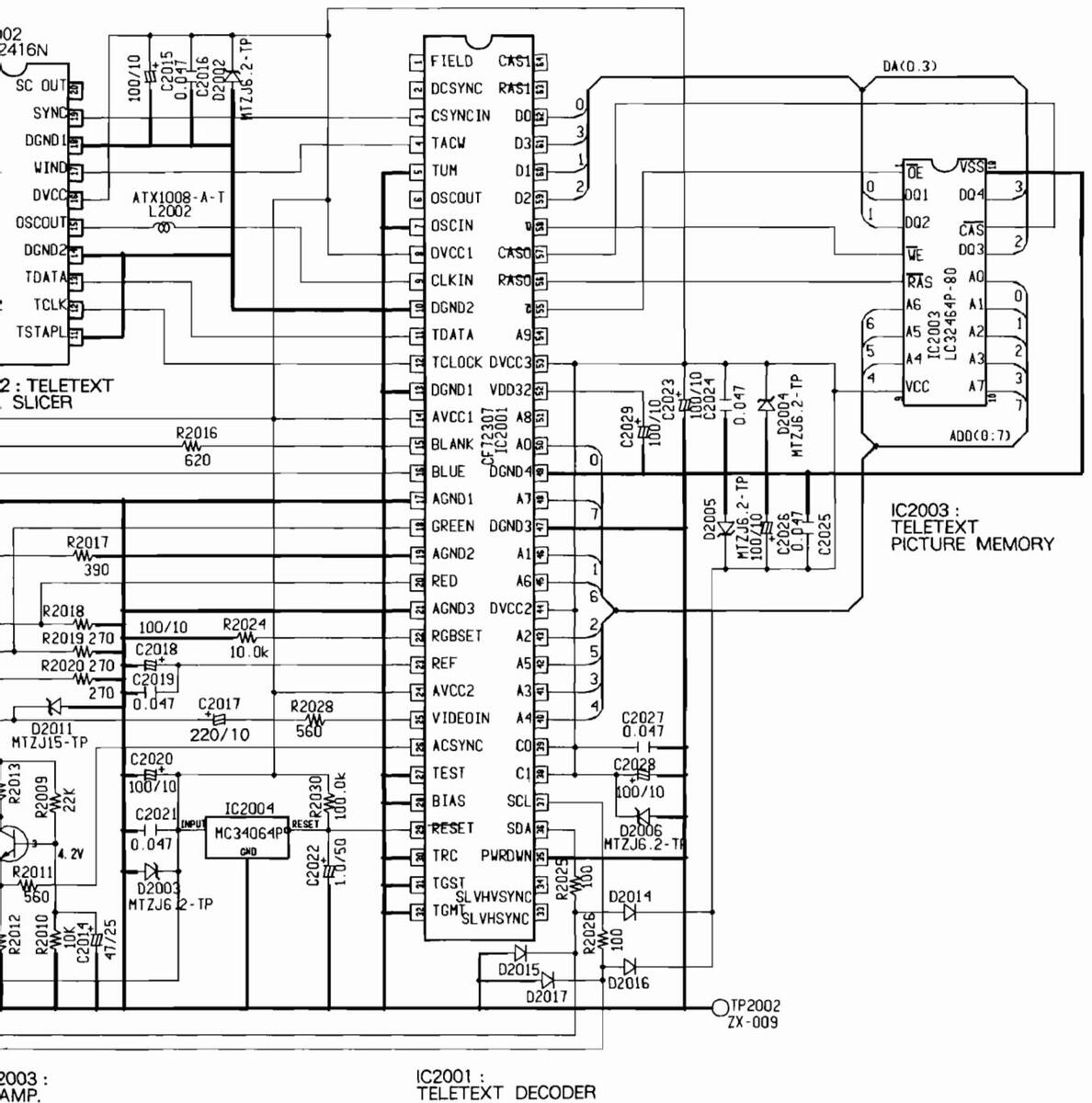
IC2001 (CF72307)
|
Pin
No. |
Voltage
(V) |
Pin
No. |
Voltage
(V) |
Pin
No. |
Voltage
(V) |
| 1 | NC | 23 | 1.4 | 45 | 3.5 |
| 2 | NC | 24 | 5 | 46 | 0 |
| 3 | 0 | 25 | 3.5 | 47 | 0 |
| 4 | 0 | 26 | 3.5 | 48 | 3.5 |
| 5 | 0 | 27 | 0 | 49 | 0 |
| 6 | NC | 28 | 0 | 50 | 0 |
| 7 | 0 | 29 | 5 | 51 | NC |
| 8 | 5 | 30 | 0 | 52 | 3.5 |
| 9 | 2.2 | 31 | 0 | 53 | 5 |
| 10 | 0 | 32 | 0 | 54 | 0 |
| 11 | 5 | 33 | NC | 55 | 3.5 |
| 12 | 0 | 34 | NC | 56 | 3.4 |
| 13 | 0 | 35 | 0 | 57 | 3.5 |
| 14 | 5 | 36 | 5 | 58 | 3.5 |
| 15 | 37 | 5 | 59 | 0 | |
| 16 | 38 | 5 | 60 | 0 | |
| 17 | 0 | 39 | 5 | 61 | 0 |
| 18 | 40 | 0 | 62 | 0 | |
| 19 | 0 | 41 | 0 | 63 | NC |
| 20 | 42 | 0 | 64 | NC | |
| 21 | 0 | 43 | 0 | ||
| 22 | 1.4 | 44 | 5 |
IC2002 (CF72416N)
|
Pin
No. |
Voltage
(V) |
Pin
No. |
Voltage
(V) |
| 1 | 2.2 | 11 | 0 |
| 2 | 2.2 | 12 | 0 |
| 3 | 1.1 | 13 | 0 |
| 4 | 0 | 14 | 0 |
| 5 | 2.4 | 15 | 2.2 |
| 6 | 2.5 | 16 | 5.0 |
| 7 | 5.0 | 17 | 0 |
| 8 | 1.6 | 18 | 0 |
| 9 | 0 | 19 | 0 |
| 10 | 1.7 | 20 | NC |
IC2003 (LC32464P-80)
|
Pin
No. |
Voltage
(V) |
| 1 | 3.5 |
| 2 | 0 |
| З | 0 |
| 4 | 3.5 |
| 5 | 3.4 |
| 6 | 3.5 |
| 7 | 0 |
| 8 | 0 |
| 9 | 5.0 |
| 10 | 3.5 |
| 11 | 0 |
| 12 | 0 |
| 13 | 0 |
| 14 | 0 |
| 15 | 0 |
| 16 | 3.5 |
| 17 | 0 |
| 18 | 0 |
SCH-5 VIDEO · UCOM ASSY (1/2)
Input Signal : PAL EBU Color-bar , AV3 input Picture quality : Standard Range : DC range (Unless otherwise noted)

SCH-11 CONVERGENCE ASSY
Input Signal : NTSC Color-bar . AV3 input Input Signal : NISC Color-bar, AV3 inpu Picture quality : Standard Range : DC range (Unless otherwise noted)
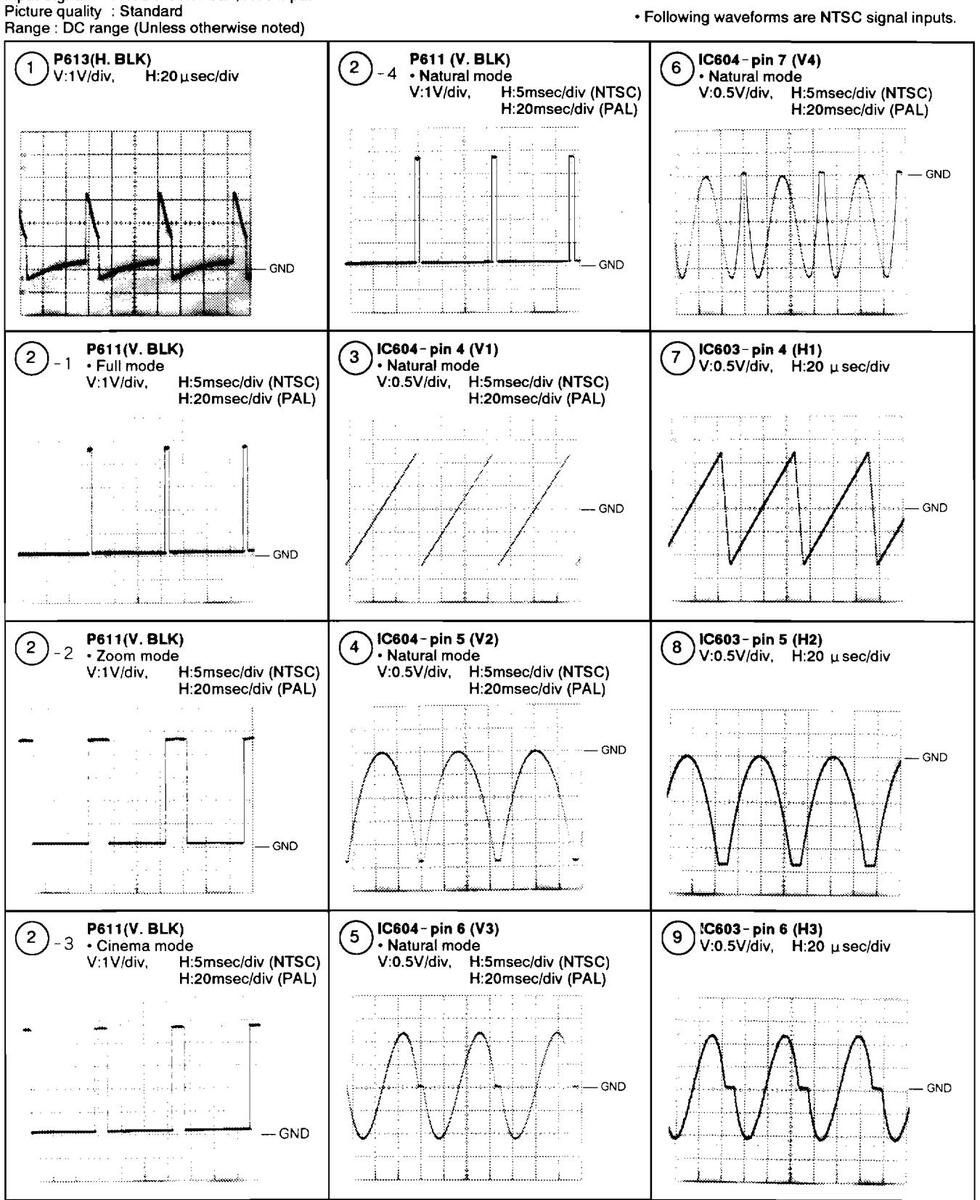

Synchronous Frequency
| NTSC | PAL | |
|---|---|---|
| H. sync |
15.734kHz
(63.556 μsec) |
15.625kHz
(64 μsec) |
| V.sync |
59.94Hz
(16.683msec) |
50Hz
(20msec) |
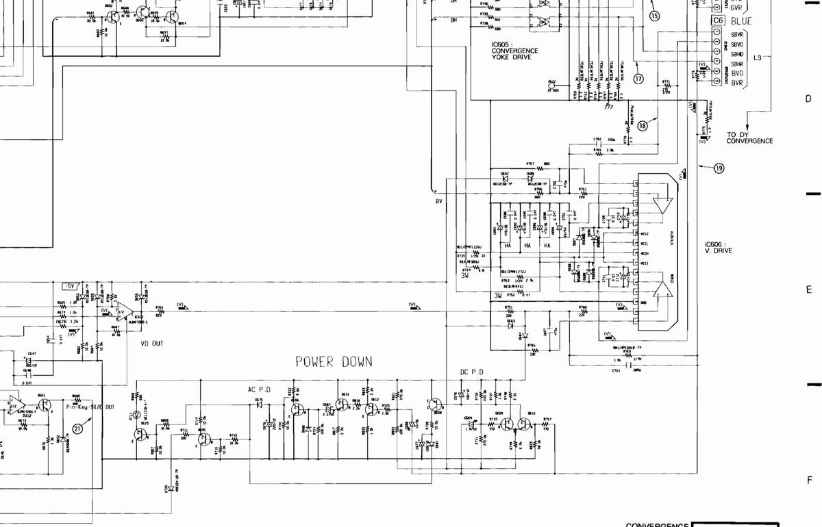
IC603 (PA0053B)
|
Pin
No. |
Voltage
(V) |
Pin
No. |
Voltage
(V) |
|---|---|---|---|
| 1 | 0.4 | 10 | 0 |
| 2 | 1.4 | 11 | 0.5 |
| 3 | 5.1 | 12 | - 1.1 |
| 4 | 0 | 13 | 0.3 |
| 5 | - 0.9 | 14 | 1.2 |
| 6 | 0 | 15 | 0 |
| 7 | - 0.9 | 16 | - 2.1 |
| 8 | 0 | 17 | 1.2 |
| 9 | - 5.0 | 18 | - 1.5 |
IC604 (PA0053B)
|
Pin
No. |
Voltage
(V) |
Pin
No. |
Voltage
(V) |
|---|---|---|---|
| 1 | 0.3 | 10 | 0 |
| 2 | 1.1 | 11 | 0.4 |
| 3 | 5.1 | 12 | - 0.9 |
| 4 | 0 | 13 | 0.3 |
| 5 | - 0.8 | 14 | 1.1 |
| 6 | 0 | 15 | 0 |
| 7 | - 1.1 | 16 | - 0.9 |
| 8 | - 0.1 | 17 | 1.2 |
| 9 | - 4.9 | 18 | - 1.5 |
IC607 (NJM072BD-E)
|
Pin
No. |
Voltage
(V) |
Pin
No. |
Voltage
(V) |
|---|---|---|---|
| 1 | - 0.1 | 5 | 0 |
| 2 | 0 | 6 | 0 |
| з | 0 | 7 | 0 |
| 4 | - 5.0 | 8 | 5.0 |
IC608 (NJM072BD-E)
|
Pin
No. |
Voltage
(V) |
Pin
No. |
Voltage
(V) |
|---|---|---|---|
| 1 | - 0.1 | 5 | - 0.1 |
| 2 | 0 | 6 | - 0.1 |
| 3 | 0 | 7 | - 0.2 |
| 4 | - 4.9 | 8 | 5.0 |
IC609 (TC4066BP)
|
Pin
No. |
Voltage
(V) |
Pin
No. |
Voltage
(V) |
| 1 | 0 | 8 | - 0.9 |
| 2 | 0 | 9 | - 0.9 |
| 3 | 0 | 10 | 0 |
| 4 | 0 | 11 | - 0.9 |
| 5 | 5.0 | 12 | - 4.9 |
| 6 | 5.0 | 13 | - 4.9 |
| 7 | - 5.0 | 14 | 5.0 |
IC605 (STK4277)
|
Pin
No. |
Voltage
(V) |
Pin
No. |
Voltage
(V) |
| 1 | 0 | 14 | 0.5 |
| 2 | 0 | 15 | 0 |
| 3 | - 1.8 | 16 | 0 |
| 4 | - 1.1 | 17 | 0 |
| 5 | 18 | 0 | |
| 6 | 0 | 19 | 0 |
| 7 | 0 | 20 | 0 |
| 8 | 0 | 21 | 24.8 |
| 9 | 0 | 22 | 25.5 |
| 10 | 0 | 23 | 0 |
| 11 | 0 | 24 | - 25.2 |
| 12 | 0 | 25 | - 25.6 |
| 13 | 0.6 |
IC611 (TC4053BP)
|
Pin
No. |
Voltage
⟨V⟩ |
Pin
No. |
Voltage
(V) |
|---|---|---|---|
| 1 | 0 | 9 | 0 |
| 2 | 0 | 10 | 0 |
| З | - 4.5 | 11 | 0 |
| 4 | - 0.7 | 12 | 0 |
| 5 | - 0.7 | 13 | 0 |
| 6 | o | 14 | 0 |
| 7 | - 4.9 | 15 | 0 |
| 8 | 0 | 16 | 5.0 |
IC606 (STK4274)
|
Pin
No. |
Voltage
(V) |
Pin
No. |
Voltage
(V) |
|---|---|---|---|
| 1 | 0 | 9 | 25.4 |
| 2 | 0 | 10 | - 24 |
| З | 0 | 11 | 0 |
| 4 | - 8.4 | 12 | - 6.0 |
| 5 | - 6.0 | 13 | - 8.4 |
| 6 | 0 | 14 | 0 |
| 7 | - 24 | 15 | 0 |
| 8 | 25.4 |
SCH-14 to 16 POWER SUPPLY ASSY
Input Signal : Color-bar , AV3 input Picture quality : Standard Bange : DC range (Unless otherwise noted)

6 PCB PARTS LIST
NOTES
- Parts marked by "NSP" are generally unavailable because they are not in our Master Spare Parts List
- The A mark found on some component parts indicates the importance of the safety factor of the part. Therefore, when replacing
- be sure to use parts of identical designation
- Parts marked by " (a)" are not always kept in stock. Their delivery time may be longer than usual or they may be unavailable
- When ordering resistors, first convert resistance values into code form as shown in the following examples
-
Ex.1 When there are 2 effective digits (any digit apart from 0), such as 560 ohm and 47k ohm (tolerance is shown by J=5%, and K=10%)
- ..... RD1/4PU56]]J ..... RD1/4PU56]]J ..... RD1/4PU473J 560 Q -> 56 × 10' -> 561 .....
- 0.5 Q → 0R5 .....
Ex 2 When there are 3 effective digits(such as in high precision metal film resistors) 5.62k Q → 562 × 10' → 5621 ..... RN1/4PC [5][6][2][1] F
• Parts marked by $$ are important parts which relate in X-rays radiation
If any of these parts need to be replaced, always replace with specified parts
• Parts marked by X are important parts which relate in X-rays radiation. If a failure occurs in any of these parts, replace the printed circuit board assembly where the relevant part has already been adjusted as a working component. Do not replace the actual part itself If any part marked by X is replaced, there is danger of being exposed to X-rays
| Mark | No. Description | Part No. | Mark No. | Description | Part No. |
|---|---|---|---|---|---|
| LIST | OF ASSEMBLIES | CONVERGEN | |||
| CONVERGENCE ASSY | AWV1520 | SEMICONDUCT | ORS | ||
| VIDEO.UCOM ASSY | AWV1542 | IC607, IC60 | 8. IC612 | NJM072BD-E | |
| IC602 | NJM78M05FAS | ||||
| NSP | TUNER ASSY (SD-T50W1) | AWV1543 | IC601 | NJM79M05FA | |
| NSP | TUNER ASSY (SD-T430W1) | AWV1586 | IC603, IC604 | 4 | PA0053B |
| - TUNER ASSY | AWZ6075 | IC606 | STK4274 | ||
| - R CONV DAC ASSY (SD-T50W1) | AWZ6076 | ||||
| - R CONV DAC ASSY (SD-T43W1) | AW26152 | IC605 | STK4277 | ||
| - G CONV DAC ASSY (SD-T50W1) | AWZ6077 | IC610 | TC4052BP | ||
| - G CONV DAC ASSY (SD-T43W1) | AWZ6153 | 1C611 | TC4053BP | ||
| - B CONV DAC ASSY (SD-T50W1) | AWZ6078 | 1C609 | TC4066BP | ||
| - B CONV DAC ASSY (SD-T43W1) | AWZ6154 | Q603, Q608, Q | 0616 | 2SA1048 | |
| A CONNECTOR ASSY | AWZ6079 | ||||
| - B CONNECTOR ASSY | AWZ6080 | Q601, Q602, 0 | 0604-0606 | 2SC2458 | |
| C CONNECTOR ASSY | AWZ6081 | 0609-0613 | 0615.0620 | 2SC2458 | |
| 111 DOCOT | D672 D673 | 155108 | |||
| NSP | AV L/O ASSY | AWV1544 | D711 | AEL1099 | |
| 1151 | L AV 1/0 ASSY | AWZ6082 | D602, D603, | D612, D675 | HSS104-02 |
| - FRONT CONTROL ASSY | AWZ6083 | 0002,0000, | 100101 00 | ||
| - AV2 ASSY | AWZ6084 | D680, D681, | D683, D684, D720 | HSS104-02 | |
| NSP | S TERMINAL ASSY | AWZ6085 | D613, D615, | D618, D621, D622 | MTZ.112 |
| 11.20000 | D624, D625, | D627, D628 | MTZ.112 | ||
| NSP | CRT DRIVE ASSY | AWV1545 | D630-D638. | D641, D645-D651 | MTZJ12 |
| 1001 | AWZ6086 | D653-D668. | D670, D671, D674 | MTZJ12 | |
| R CRT DRIVE ASSY | AWZ6087 | ||||
| G CRT DRIVE ASSY | AWZ6088 | D677-D679. | D682, D685 | MTZJ12 | |
| B CRT DRIVE ASSY | AWZ6089 | D700-D710 | MTZ.112 | ||
| AC IN ASSY | AWZ6090 | D652 | MTZJ20 | ||
| AWZ6091 | D606-D609 | MTZ.I6 8 | |||
| - D CONNECTOR ASSY | AWZ6092 | D611 | RD5_LESB3 | ||
| - POWER DOWN ASSY | AWZ6093 | D686-D699 | S5688G | ||
| RELAY DRIVE ASSY | AWZ6094 | 000000 | |||
| CAPACITORS | |||||
| ∽ | POWER SUPPLY ASSY | AWV1546 | C702 | CCCSL151.150 | |
| A | DIGITAL ASSY | AWV1548 | C689 | CEANP010M50 | |
| C688 | CEANP100M50 | ||||
| TV FRONT END | AXF1085 | C609, C638- | C642 | CEAS010M50 | |
| C674 | CEAS100M50 | ||||
| C613, C621- | C623, C629, C630 | CEAS101M10 | |||
| C647, C657, | C664-C667 | CEAS101M10 | |||
| C677, C678, | C706, C708 | CEAS101M10 | |||
| C662 C673 | 0000 | CE45220M50 |
۵n
| Mark | No. | Description | Part No. | Mark | No. | Description | Part No. |
|---|---|---|---|---|---|---|---|
| C676 | CEAS221M10 | CN611 | PLUG 6-P | KM250MA6 | |||
| C687 | CEAS2R2M50 | CN612 | PLUG 6-P | KM250MA6B | |||
| C658, C660 | CEAS330M35 | CN610 | PLUG 6-P | KM250MA6R | |||
| C614, C615 | , C649, C650 | CEAS331M6 | CN601 | PLUG 8-P | KM250MA8R | ||
| C661 | CEAS470M25 |
CN602
SCREW |
PLUG 9-P |
KM250MA9B
PBZ30P080FMC |
|||
| C643 | CEASR47M50 | ||||||
| C605, C606 | CEHAQ101M10 | ||||||
| C603, C604 | CEHAQ470M25 | ||||||
| C710, C712 | CEHAQ470M35 | ||||||
| C679-C683 | , C692, C696 | CEHAQ471M35 | VIDE | -0.00 | OM ASY | ||
| C663 | CFTYA184J50 | SEMI | COND | UCTORS | |||
| C645, C656 | CFTYA224J50 | IC3303 | AT24C16-10PC | ||||
| C691, C713 | CKCYB102K50 | 101007 | BA7606 | ||||
| C659, C675 | CKCYB331K50 | ICIOUI | CX20125 | ||||
| C697, C700 | CKC1B4/1K50 |
IC1005
IC3302 |
MC14053BCP
MC34064P |
||||
| C703 | CKCYB681K50 | ||||||
| C709, C711 | CKCYF103Z50 | IC1009 | NJM7805FAS | ||||
| C601, C602 | c, C607, C608, C612 | CKCYF473250 | 101008 | NJM7809FAS | |||
| C616-C620 | , C624, C625 | CKCYF473250 | 101002 | PA0030 | |||
| C627, C628 | , C631, C632, C646 | CKCYF473250 | 1C3301 | PD5372 | |||
| C648, C652 | -C655, C668-C672 | CKCYF473Z50 | 101003 | i de la construcción de la constru | 1A8759BN | ||
| C684-C686 | , C693-C695, C698 | CKCYF473Z50 | IC3304 | , IC3305 | TC4094BP | ||
| C701, C704 | , C705, C707, C714 | CKCYF473Z50 | IC1006 | TC74HC4053AP | |||
| C633-C636 | CKCYX473M16 | IC1004 | TDA4566 | ||||
| C611, C626 | i | CQMA102J50 |
Q1003,
Q1022- |
Q1013, Q1015, Q1016, Q1018
Q1024, Q1028, Q1038, Q1041 |
2SA1048
2SA1048 |
||
| C637, C644 | CQMA471J50 | ||||||
| C610 | CQPA152J100 | Q1054, | Q1062, Q1067, Q1068, Q1070 | 2SA1048 | |||
| Q1073, | Q1075, Q1077, Q1080, Q1082 | 2SA1048 | |||||
| RESIS | STORS | Q1086, | Q1087, Q1093, Q1098, Q1099 | 2SA1048 | |||
| R603-R606 | , R622, R627 | RD1/2PM221J | Q3301, | Q3309, Q3311-Q3316, Q3331 | 2SA1048 | ||
| R828-R830 | RD1/2PM221J | Q3344 | 2SA1048 | ||||
| R771 | RD1/2PM271J | 01001 | 01008 01004 01000 | 0000 (50 | |||
| R(12-R(14 | D750 | KD1/2PM4 (UJ | Q1001, | Q1002, Q1004-Q1008 | 2502458 | ||
| K130, K135 | , R750 | RD1/2PMFL220J | Q1011, | Q1012, Q1017, Q1019-Q1021 | 2502458 | ||
| D752 | DD1/20ME1 2721 | Q1025- |
Q1027, Q1029-Q1037
01040 01042-01040 |
2502458 | |||
| R133 | Q1039, |
Q1040, Q1042-Q1049
A1053 A1056 A1058 A1060 |
2502450 | ||||
| R729 | RS21 MFR47 I | A1021 | 41035, 41030, 41036, 4100 | 2302430 | |||
| R775 | RS3LMF010. | 01063 | 01065 01066 01071 01072 | 2502458 | |||
| R602, R804 | RS3LMF100. | 01074 | 01076, 01078, 01079, 01081 | 2SC2458 | |||
| 1000, 1001 | 01083- | 01085. 01088-01092 | 2SC2458 | ||||
| R759, R762 | . R764, R767, R768 | RS3LMF3R3J | Q1094- | Q1097, Q1100, Q3302-Q3307 | 2SC2458 | ||
| R770 | RS3LMF3R3J | Q3310, | Q3317-Q3323, Q3325-Q3327 | 2SC2458 | |||
| R601, R805 |
,
, |
RS3LMF4R7J | |||||
| R734 | RS3LMF6R8J | Q3329, | Q3330, Q3343 | 2SC2458 | |||
| R736. R752 | RS3LMFR47J | Q3328 | 2SC2878 | ||||
| Q3308 | 2SD880 | ||||||
| VR602 | VRTS6VS223 | Q1057, | Q1059, Q1061 | 2SK117 | |||
| VR603 | VRTS6VS472 | Q1009, | Q1010, Q1014, Q1050, Q1055 | DTC124ES | |||
| VR601 | VRTS6VS473 | ||||||
| Other Res | sistors | Q1064, | Q1069, Q1101, Q3332-Q3342 | DTC124ES | |||
| OTUE | D1001- | HSS104-02 | |||||
| OTHE | SCDEW | 4841056 | D1012- | D1015, D1017-D1030, D1040 | HSS104-02 | ||
| JUEAT SINK | м |
ADA 1050
ANH-607 |
D1043- | D1045, D1046-D1059 | HSS104-02 | ||
| ANH1165 | 01002- | 01003, 01072-01089 | NS5104-02 | ||||
| SCREW | ISE . | BR730P080FCU | D1091- | D1004 D1006-D1108 D1118 | HSS104-02 | ||
| SCRFW | BBZ30P080F7K | D1121 | D1123 D1124 D1126-D1128 | HSS104-02 | |||
| Jenth | DDDOVI OOVI DIL | D3302 | D3305-D3311, D3313-D3318 | HSS104-02 | |||
| CN605, CN6 | 507. CN609 11P PLUG | KM2001A1 | D3354 | D3362-D3366, D3388-D3391 | HSS104-02 | ||
| CN606 12 | P PLUG | KM2001A12 | D1066- | D1071, D1090, D1095, D1117 | MTZJ12 | ||
| CN604 13 | BP PLUG | KM2001A13 | |||||
| CN608 15 | SP PLUG | KM2001A15 | |||||
| CN603 PL | UG 11-P | KM250MA11B |
| Mark | No. | Description | Part No. | Mark | No. | Description | Part No. |
|---|---|---|---|---|---|---|---|
| D3360, D3 | 383-D3386 | MTZJ15 | C3307 | CEASOR1M50 | |||
| D3301, D3 | 303, D3304, D3319-D3340 | MTZJ6.8 | C1002, | C1018, C1036, C3302 | CEAS100M50 | ||
| D3342-D3 | 353, D3356, D3361 | MTZJ6.8 | C1037. | C3312, C3322, C3334, C3337 | CEAS101M10 | ||
| D3367-D3 | 382, D3387, D3392 | MTZJ6.8 | C3343 | ,, | CEAS101M10 | ||
| D1047 | RD3. 0ESB2 | C1007, | C1025, C1074, C1093, C1098 | CEAS101M25 | |||
| D1041. D1 | .042 | RD4. 3ESB3 | C1101. | C1122, C1168, C1175 | CEAS101M25 | ||
| D3312 | RD5. 1ESB2 | C1004, | C1020, C1060 | CEAS220M50 | |||
| D1011 | RD5. 1ESB3 | C1095 | CEAS221M16 | ||||
| D3341, D3 | 355, D3357-D3359 | RD6. 2ESB2 | C1041 | CEAS222M16 | |||
| D1006, D1 | 016, D1037-D1039 | S5688G | C1085, | C1097 | CEAS331M16 | ||
| COILS | S | C1049, | C3306 | CEAS3R3M50 | |||
| L1006 | ATG1009 | C1010, | C1014, C1029, C1061, C1105 | CEAS470M25 | |||
| L1010 | ATG1026 | C1110, | C1111, C1120, C1136, C1137 | CEAS470M25 | |||
| L1001, L1 | .008 | ATG1027 | C1139, | C1141, C1143, C1146 | CEAS470M25 | ||
| L1007 | ATG1033 | C1161, | C1162, C1182, C3315 | CEAS470M25 | |||
| DL1002 | ATN1014 | C3310 | CEAS471M25 | ||||
| DI 1001 | ATN1036 | C1006 | C1112 C1155 C1170 |
CEAS4TIM25
CEAS4R7M50 |
|||
| 13301 | LAUIOOK | C1169 | 01112, 01103, 01110 | CEAS6R8M50 | |||
| 11003 | LAU121K | C1130- | C1133 C1147 C1148 | CEASE 33M50 | |||
| 1 1002 [ ] | 014 | LAU270K | C1019 | CEASR47M50 | |||
| L1002, D1 | .017 | LAU390K | 01010, | OLMORY (MOU | |||
| C1015 | CEASR68M50 | ||||||
| L1004 | LAU3R3K | C1150 | CEHAQ102M10 | ||||
| L1015, L1 | .016 | LAU470K | C1149 | CEHAQ102M16 | |||
| L1011-L1 | .013 | LAUGRAK | C1153, | CEHAQ470M25 | |||
| L1009 | LAUSRZK | C3301, | 03346 | CFTXA103J50 | |||
| CAPA | CITORS | 5 | C1046, | C1048, C1052, C1055, C1057 | CFTXA104J50 | ||
| TC3301 | ACM-020 | C1059 | CFTXA104J50 | ||||
| C1033 | CCCCH070D50 | C1079 | CFTXA105J50 | ||||
| C1042 | CCCCH080D50 | C1005, | C1069, C1176–C1179 | CFTXA224J50 | |||
| C1076 | CCCCH120J50 | C1038, | C1181 | CKCYB102K50 | |||
| C1022, C1 | 1024 | CCCCH121J50 | 01004 | OWOURLOOVED | |||
| 01104 | 000001180150 | C1034, | CKCYB103K50 | ||||
| C1104 | CCCCH180J50 | C1075, | 13305, 13308 | CKCYB1U3K50 | |||
| C1026, C1 | CCCCU181J50 | C1084 | C1082 | CKCIB331K50 | |||
| 1072, 01129 | 000001220350 | C11062, | C1005 | CKCKDAJIKED | |||
| C1040, C1 | 1007 | 000000220150 | 01124, | C1120 | CACID4/1A00 | ||
| 01080 | CCCH330130 | C3303 | CKCVR172K50 | ||||
| C1028 C1 | 077 | 000004300150 | C1003 | CKCVR821K50 | |||
| C1020, C1 | CCCCH470150 | C1035 | C1043 C1045 C1050 C1065 | CKCYF103750 | |||
| C1100 | CCCCH820150 | C1033, | C1086 C1103 C1121 C1123 | CKCYF103Z50 | |||
| C1054 C1 | 058 01090-01092 | CCCSL101.150 | C1138 | C1140 C1142 C1151 C1152 | CKCYF103Z50 | ||
| C1116, C1 | 1117, C1145, C1173, C1174 | CCCSL101J50 | |||||
| 00001 101 100 | C1183, | C3304, C3309, C3313, C3316 | CKCYF103Z50 | ||||
| C3336, C3 | 3339-C3342 | CCCSL101J50 | 03323, | U3325, U3329, U3335, U3338 | CKCYF103250 | ||
| C1081, C1 | CCCSL121J50 | C3344 | CKCYF103250 | ||||
| C1008, C1 | 1009, C1011, C1012, C1088 | CCCSL151J50 | C1156 | C11C7 | CKCYF223250 | ||
| 1107, 01157, 01158 | CCCSL 221 J50 | CI160, | CKCYF 472250 | ||||
| (3332, 03 | 3333 | (((SL221)50 | C1013. | C1106, C1163 | CKCYF473Z50 | ||
| C3324 | CCCSL270.150 | C1023 | C1063, C1094, C1096, C1102 | CKCYX104M25 | |||
| C1144 | CCCSL271.150 | C1128 | CKCYX104M25 | ||||
| C1027 | CCCSL390.150 | C1099 | COMA223.150 | ||||
| C1027 | CCCSL560.150 | C1062 | COMA393.150 | ||||
| C1017, C1 | 1115, C1125, C3331 | CCCSL680J50 | 01000 | C agina 10 0 | |||
| C1110 C1 | 1114 02245 | CCCS1 990 150 | C1070 | C2221 | CQMA472J50 | ||
| 1114, 03343 | CEANDODINED | C1039, | C1078 | COMARAIJJU | |||
| C1134, C | 1133, 01171 | CEANFORIMOU | U1000, | 01010 | CAWV302120 | ||
| C10/3 | 021 01031 01064 02211 | CEANF2R2MOU | DEC | STOP | |||
| 1021, 01031, 01004, 03311 | CEASUIUMSU | LE9 | R1049 | ACN1050 | |||
| 03314,03 | 3317-03320, 03330 | CENOVIUMOU | P1100 | R1192 | RD1 /201100 1 | ||
| R3320 | N1100 | RD1/2PM1221 | |||||
| R1170 | R1172 R1174 R3474 R3475 | RD1/2PM221 1 | |||||
| R1146- | R1148. R1189 | RD1/2PM471. |
| Mark | No. | Description | Part No. | Mark | No. | Description | Part No. |
|---|---|---|---|---|---|---|---|
| R1197 | RD1/2PMFL4R7J | D1534, I | D1535, D1753 | HSS104-02 | |||
| R3422 | RD1/4PMFL3R3J | D1536. I | D1651, D1652 | MTZJ15 | |||
| R3567 | RN1/4PC2201F | D1515. I | D1516, D1527, D1537 | MTZ.16.8 | |||
| R1431 | RS1LMF010J | D1507 | RD33ESB3 | ||||
| R1430 | RS1LMFR47J | D1518 | RD5, 1ESB | ||||
| D1752 | RD8, 2ESB2 | ||||||
| R3326 | RS1MMF150J | ||||||
| R1397 | RS3LMF1R8J | COIL | S AND | FILTERS | |||
| R1049 | RS3LMF4R7J | L1509, I | L1705 | ATC-250 | |||
| VR1001 (4 | 470Ω) | ACP1039 | L1510 | ATE-067 | |||
| VR1002, VF | R1003 | VRTS6HS471 | F1510 | ATF-114 | |||
| Other Res | sistors | F1504 | ATF1046 | ||||
| ATU | F1508, I | F1513, F1514 | ATF1051 | ||||
| UTHE | CN1002 SC | YOKET EA_P | AKD1161 | F1509 | ATE1059 | ||
| HEAT SINK | 2 | ANH-300 | F1502 | ATE1056 | |||
| HEAT SINK | ( | ANH-880 | F1501 | 21507 | ATE1055 | ||
| SHIFLD CA | ASE | ANH1165 | F1500,1 | 1991 | ATE1132 | ||
| SHIELD PI | ATE | ANK1500 | F1511 | ATF1132 | |||
| A11 1107 | |||||||
| X3301 CH | ERAMIC RESONATOR | ASS1015 | F1512 | ATF1138 | |||
| X1003 CH | ERAMIC RESONATOR | ASS1019 | F1503 | ATF1140 | |||
| X1001 CF | RYSTAL RESONATOR | ASS1091 | F1506 | ATF1180 | |||
| X1002 CF | RYSTAL RESONATOR | ASS1092 | F1701 | ATF1181 | |||
| SCREW | BBZ30P080FMC | L1517 | ATG1031 | ||||
| CN1000 1 | KN2001415 | 115151 | 1756 11757 11796 | ATV1000 | |||
| CN1009 1 | KM2001A15 | L1515,1 | L1(50, L1/57, L1780 | AIXIUUS | |||
| CN1010 0 | KM2001A3 | 11502 1 | 1509 | LAUIDON | |||
| CN3305 C | KM2001A0 | 11503,1 | 1702 11704 | ||||
| CN3302 F | KM250MA11 | 11501 | 1502,01704 | LAUINOJ | |||
| 0100000 1 | 10/2000/111 | D1001, 1 | 21002, 21011, 21010 | LHUZHZK | |||
| CN3301 F | PLUG 6-P | KM250MA6 | L1518-1 | L1520, L1651, L1703 | LAU2R2K | ||
| CN1001 F | PLUG 9-P | KM250MA9R | L1785 | LAU2R7J | |||
| CN1011 1 | 13P SOCKET | KP250NA13 | L1753 | LAU2R7K | |||
| CN1012, CN | V3306 SOCKET 15-P | KP250NA15 | L1782 | LAU3R3J | |||
| CN3304 S | SOCKET 4-P | KP250NA4 | L1751 | LAU3R3K | |||
| CN3303 S | SOCKET 7–P | KP250NA7 | |||||
| L1512 | LAU3R9J | ||||||
| L1513, J | L1/83, L1/84 | LAU4R7J | |||||
| LI(54, 1 | L1/54 | ||||||
| THEFT | 11214 | ||||||
| IUN | ER ASS | 51 | 11504 | 1701 | |||
| SEMI | CONDUC | TORS | L1304, I | LAURZZJ | |||
| U LINII | IC1752 | AT24C01A10PC | CAPA | CITOR | IS | ||
| IC1651 | CXA1734S | C1660 | (3. 3 μ F, 50V) | ACH1128 | |||
| IC1701 | LA7710 | C1653 | (10 μ F, 50V) | ACH1129 | |||
| IC1501 | UPC1823ACU | TC1501 | ACM-022 | ||||
| 1C1751 | UVS1101A24 | C1519 | CCCCH010C50 | ||||
| C1518, ( | C1550 | CCCCH020C50 | |||||
| Q1524, Q15 | 527, Q1528, Q1533, Q1756 | 2SA1048 | |||||
| Q1501, Q15 | 510, Q1512, Q1517, Q1523 | 2502458 | C1506, ( | C1507, C1510, C1539, C1551 | ССССН030С50 | ||
| Q1525, Q15 | 529–Q1531, Q1536, Q1543 | 2502458 | C1515, ( | C1516, C1540, C1614, C1634 | CCCCH040C50 | ||
| Q1545, Q16 | 551, Q1653, Q1704 | 2SC2458 | C1517, ( | C1557, C1561, C1613, C1633 | CCCCH050C50 | ||
| Q1751-Q17 | 754, Q1757, Q1758 | 2SC2458 | C1508, ( | 21611 | CCCCH060D50 | ||
| 01781 013 | 782 | 2502458 | C1612 | CCCCHU70D50 | |||
| 01502-019 |
102
507 01535 01540 01541 |
2502450 | C1548 ( | ~15 84 | CCCCU080DE0 | ||
| 703 01759 | 2502000 | C1556 | 21504 | CCCCH080D50 | |||
| 519 01526 01532 01783 | 2502878 | C1543 | CCCCH120150 | ||||
| 513, w 1320, w 1332, w 1703 | 25C2010 | C1701 ( | °1781 | CCCCH121150 | |||
| ալութուք ավել | C1753 | CCCCH151 150 | |||||
| Q1511, Q15 | 513–Q1515, Q1542, Q1544 | XDC124ES | 00001101000 | ||||
| Q1755 | . , , | XDC124ES | C1617. | C1618 | CCCCH180J50 | ||
| D1508-D15 | 514, D1517, D1533 | 1SS85 | C1619 | CCCCH220J50 | |||
| D1501-D15 | 506, D1519-D1521 | HSS104-02 | C1716 | CCCCH390J50 | |||
| D1523-D15 | 526, D1530-D1532 | HSS104-02 | C1783 | CCCCH271J50 | |||
| C1565 | CCCCH330J50 |
| Mark | No. | Description | Part No. |
|---|---|---|---|
| C1784. C17 | 88 | CCCCH560J50 | |
| C1531 | CCCCH680J50 | ||
| C1782 | CCCCH820J50 | ||
| C1527-C15 | 30, C1564, C1602 | CCCSL101J50 | |
| C1754, C17 | 55 | CCCSL121J50 | |
| C1620 | CCCSL221J50 | ||
| C1597 | CCCSL470J50 | ||
| C1512 | CCCSL560J50 | ||
| C1621 | CCCSL680J50 | ||
| C1576, C16 | 54, C1659, C1720 | CEAS010M50 | |
| C1503, C15 | 72, C1596, C1598, C1652 | CEAS100M50 | |
| C1713, C17 | 14 | CEAS100M50 | |
| C1526, C176 | 67 | CEAS101M10 | |
| C1552, C15 | 54, C1667, C1705, C1707 | CEAS101M25 | |
| C1523 | CEAS102M16 | ||
| C1715 | CEAS220M50 | ||
| C1604 | CEAS221M10 | ||
| C1703 | CEAS221M16 | ||
| C1570, C15 | 79, C1588, C1590, C1591 | CEAS470M25 | |
| C1593, C159 | 99, C1600, C1670, C1752 | CEAS470M25 | |
| C1757, C17 | 63. C1766. C1768. C1771 | CEAS470M25 | |
| C1786 | CEAS470M25 | ||
| C1586 | CEAS471M16 | ||
| C1574, C16 | 55, C1656, C1664-C1666 | CEAS4R7M50 | |
| C1668, C16 | 69, C1758-C1762 | CEAS4R7M50 | |
| C1772, C17 | 73, C1790, C1791 | CEAS4R7M50 | |
| C1501 | CEAS6R8M50 | ||
| C1568, C157 | 77, C1581, C1661 | CEASR47M50 | |
| C1657 | CFTXA224J50 | ||
| C1622 | CFTXA334J50 | ||
| C1562 | CFTYA104J50 | ||
| C1504, C150 | 05, C1509, C1511 | CKCYB102K50 | |
| C1513, C151 | 14, C1520, C1536, C1542 | CKCYB102K50 | |
| C1545-C154 | 47, C1549, C1553, C1555 | CKCYB102K50 | |
| C1558, C15 | 59, C1582, C1583, C1585 | CKCYB102K50 | |
| C1595, C16 | 10, C1625, C1702, C1708 | CKCYB102K50 | |
| C1710 | CKCYB102K50 | ||
| C1560, C156 | 53, C1566, C1567, C1580 | CKCYB103K50 | |
| C1605, C16 | 16, C1711, C1712, C1717 | CKCYB103K50 | |
| C1774 | CKCYB103K50 | ||
| C1573. C165 | 51, C1658, C1719 | CKCYB222K50 | |
| C1792 | CKCYB681K50 | ||
| C1521, C152 | 22, C1524, C1525, C1534 | CKCYF103Z50 | |
| C1544, C156 | 69, C1578, C1587, C1589 | CKCYF103Z50 | |
| C1592, C159 | 94, C1601, C1671, C1672 | CKCYF103Z50 | |
| C1704, C170 | 06, C1709, C1718, C1751 | CKCYF103Z50 | |
| C1756, C176 | 54, C1765, C1769, C1770 | CKCYF103Z50 | |
| C1785, C178 | 87, C1789 | CKCYF103Z50 | |
| C1575 | CQMA153J50 | ||
| C1663 | CQMA272J50 | ||
| C1662 | CQMA473J50 | ||
| RESIS | TORS | ||
| R1504 | RD1/2PM562J | ||
| R1517, R15 | 18 | RD1/2PM681J | |
| R1550 | RD1/4PMFI1011 |
| Mark | No. | Description | Part No. |
|---|---|---|---|
| R1703 | RD1/4PMFL681J | ||
| R1655 | - | RN1/4PC4302F | |
| R1656 | RN1/4PC6202F | ||
| R1606 | RS2LMF4R7J | ||
| VR1502( | 4.7kΩ) | ACP1042 | |
|
VR1501
Other R |
esistors |
VRTS6VS105
RD1/4PU |
OTHERS
| PLUG CO | ORD | ADE-082 | |
|---|---|---|---|
| KN9999 | GROUND | PLATE | ANK-142 |
| X1501 | CERAMIC | RESONATOR(15.675kHz) | ASS1122 |
| SCREW | BBZ30P060FMC |
R CONV DAC ASSY
CONTRAST OF AWZ6076 AND AWZ6152
AWZ6076 and AWZ6152 have the same construction except for the following :
| Symbol & | Par | t No. |
|---|---|---|
| Description | AWZ6076 | AWZ6152 |
|
R3036
R3044 |
Not used
RD1/4PU134J |
RD1/4PU202J
RD1/4PU154J |
• PARTS LIST FOR AWZ6076 SEMICONDUCTORS
| IC3001 |
|---|
| D3002-D3005, D3007, D3008 |
| D3001, D3006 |
| TU2001 |
CAPACITORS
| C3006, | C3007, | C3009, | C3010 |
|---|---|---|---|
| C3008 | |||
| C3003, | C3005 | ||
| C3001 | C3002 | C3004 |
CCCCH101J50 CEAS100M50 CEAS331M6 CKCYF473Z50
PM0002B MTZJ12 MTZJ6.8 NTH5D102KA
OTHERS
RD1/4PMFL101J RD1/4PMFL3311
RD1/4PMFL331J RD1/4PMFL4711
RESISTORS
| IERO | ||
|---|---|---|
| CN3002 | 11P | SOCKET |
| CN3001 | 13P | SOCKET |
All Resistors
KP2001A11L
R1539 R1513 R1533 R1710


 Loading...