

Page 1
http://www.pioneer.co.uk
(or http://www.pioneer.eu)
En
1
Page 2
Thank you for buying this Pioneer product.
S001_En
Selecting fine audio equipment such as the unit
you’ve just purchased is only the start of your
musical enjoyment. Now it’s time to consider how
you can maximize the fun and excitement your
equipment offers. This manufacturer and the
Electronic Industries Association’s Consumer
Electronics Group want you to get the most out of
your equipment by playing it at a safe level. One that
lets the sound come through loud and clear without
annoying blaring or distortion-and, most importantly,
without affecting your sensitive hearing.
Sound can be deceiving. Over time your hearing
“comfort level” adapts to higher volumes of sound.
So what sounds “normal” can actually be loud and
harmful to your hearing. Guard against this by
setting your equipment at a safe level BEFORE your
hearing adapts.
To establish a safe level:
• Start your volume control at a low setting.
• Slowly increase the sound until you can hear it
comfortably and clearly, and without distortion.
Once you have established a comfortable sound
level:
• Set the dial and leave it there.
Taking a minute to do this now will help to prevent
hearing damage or loss in the future. After all, we
want you listening for a lifetime.
We Want You Listening For A Lifetime
Used wisely, your new sound equipment will
provide a lifetime of fun and enjoyment. Since
hearing damage from loud noise is often
undetectable until it is too late, this manufacturer
and the Electronic Industries Association’s
Consumer Electronics Group recommend you avoid
prolonged exposure to excessive noise. This list of
sound levels is included for your protection.
Decibel
Level Example
30 Quiet library, soft whispers
40
Living room, refrigerator, bedroom away from traffic
50 Light traffic, normal conversation, quiet office
60 Air conditioner at 20 feet, sewing machine
70 Vacuum cleaner, hair dryer, noisy restaurant
80
Average city traffic, garbage disposals, alarm clock
at two feet.
THE FOLLOWING NOISES CAN BE DANGEROUS
UNDER CONSTANT EXPOSURE
90
Subway, motorcycle, truck traffic, lawn mower
100 Garbage truck, chain saw, pneumatic drill
120 Rock band concert in front of speakers,
thunderclap
140 Gunshot blast, jet plane
180 Rocket launching pad
Information courtesy of the Deafness Research Foundation.
Please read through these operating instructions so you will know how to operate your model properly.
After you have finished reading the instructions, put them away in a safe place for future reference.
Contents
Before you start
What’s in the box
About the EX series
Technology behind the S-8EX . . . . . . . . . . . . . . . . . . . . . . . . . . . . . 4
CST. . . . . . . . . . . . . . . . . . . . . . . . . . . . . . . . . . . . . . . . . . . . . . . . 4
Ceramic Graphite Diaphragm. . . . . . . . . . . . . . . . . . . . . . . . . . . . 4
Magnesium Alloy Diaphragm . . . . . . . . . . . . . . . . . . . . . . . . . . . . 4
Bass Drivers . . . . . . . . . . . . . . . . . . . . . . . . . . . . . . . . . . . . . . . . . 4
Bass Enclosure Construction . . . . . . . . . . . . . . . . . . . . . . . . . . . . 4
Crossover Networks . . . . . . . . . . . . . . . . . . . . . . . . . . . . . . . . . . . 5
Collaboration with Air Studios . . . . . . . . . . . . . . . . . . . . . . . . . . . 5
Installation and Placement
How to install . . . . . . . . . . . . . . . . . . . . . . . . . . . . . . . . . . . . . . . . . 6
When installing directly on the floor . . . . . . . . . . . . . . . . . . . . . . . 6
Using the furnished speaker base . . . . . . . . . . . . . . . . . . . . . . . . 6
Using the Pioneer Speaker Stand CP-7EX. . . . . . . . . . . . . . . . . . . 7
Choosing Where To Place The Speaker Systems . . . . . . . . . . . . . 7
For U.S. model
Connections
Connecting to an amplifier. . . . . . . . . . . . . . . . . . . . . . . . . . . . . . . .8
Connecting the cables . . . . . . . . . . . . . . . . . . . . . . . . . . . . . . . . . . .8
Single-Wire Connections. . . . . . . . . . . . . . . . . . . . . . . . . . . . . . . .9
Bi-Wire Connections . . . . . . . . . . . . . . . . . . . . . . . . . . . . . . . . . . .9
Bi-Amplification Connections . . . . . . . . . . . . . . . . . . . . . . . . . . .10
Other Information
Using the foam plugs. . . . . . . . . . . . . . . . . . . . . . . . . . . . . . . . . . .11
Using foam plugs A only . . . . . . . . . . . . . . . . . . . . . . . . . . . . . . .11
Using both foam plugs A and B. . . . . . . . . . . . . . . . . . . . . . . . . .11
Attaching/Removing the Grille Cover . . . . . . . . . . . . . . . . . . . . . . .11
Cleaning the speaker cabinet. . . . . . . . . . . . . . . . . . . . . . . . . . . . .11
Specifications . . . . . . . . . . . . . . . . . . . . . . . . . . . . . . . . . . . . . . . .12
2
En
Page 3
Before you start
WARNING: Handling the cord on this product or
cords associated with accessories sold with the
product will expose you to chemicals listed on
proposition 65 known to the State of California and
other governmental entities to cause cancer and
birth defect or other reproductive harm.
D36-P4_A_En
Wash hands after handling
If you want to dispose this product, do not mix it with general household waste. There is a separate collection system for used
electronic products in accordance with legislation that requires proper treatment, recovery and recycling.
Private households in the member states of the EU, in Switzerland and Norway may return their used electronic products free of charge to
designated collection facilities or to a retailer (if you purchase a similar new one).
For countries not mentioned above, please contact your local authorities for the correct method of disposal.
By doing so you will ensure that your disposed product undergoes the necessary treatment, recovery and recycling and thus prevent potential
negative effects on the environment and human health.
K058_A_En
• The nominal impedance of this speaker system is 6 Ω.
Connect the speaker system to an amplifier with a load
impedance ranging from 6 Ω to 16 Ω (a model with “6 Ω –
16 Ω” displayed on the speaker output terminals).
In order to prevent damage to the speaker system resulting
from input overload, please observe the following precautions:
• Do not supply power to the speaker system in excess of the
maximum permissible input.
• When using a graphic equalizer to emphasize loud sounds in
the high-frequency range, do not use excessive amplifier
volume.
• Do not try to force a low-powered amplifier to produce loud
volumes of sound (the amplifier’s harmonic distortion will be
increased, and you may damage the speaker).
Caution: installation
• When placing this unit, ensure that it is firmly secured and
avoid areas where it may be likely to fall and cause injury in the
event of a natural disaster (such as an earthquake).
• Do not attach these speakers to the wall or ceiling. They may
fall off and cause injury.
• Do not install your speakers overhead on the ceiling or wall. If
improperly attached, the speaker grille can fall and cause
damage or personal injury.
• Switch off and unplug your AV equipment and consult the
instructions when connecting up components. Make sure you
use the correct connecting cables.
Caution: in use
• Do not place the speaker on an unstable surface. It could
present a hazard if it falls, as well as damaging the equipment.
• Do not use the speaker to output distorted sound for long
periods of times. This can result in a fire hazard.
• Do not sit or stand on the speaker, or let children play on the
speaker.
• Do not put large or heavy objects on top of the speaker.
• Do not place magnetic objects such as screwdrivers or iron
parts near the tweeter or midrange. Since the speakers use
strong magnets, the objects may be attracted, causing injury
or damaging the diaphragm.
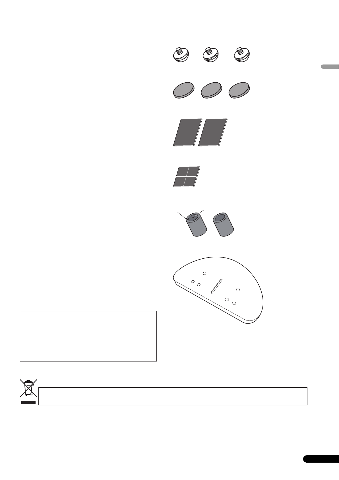
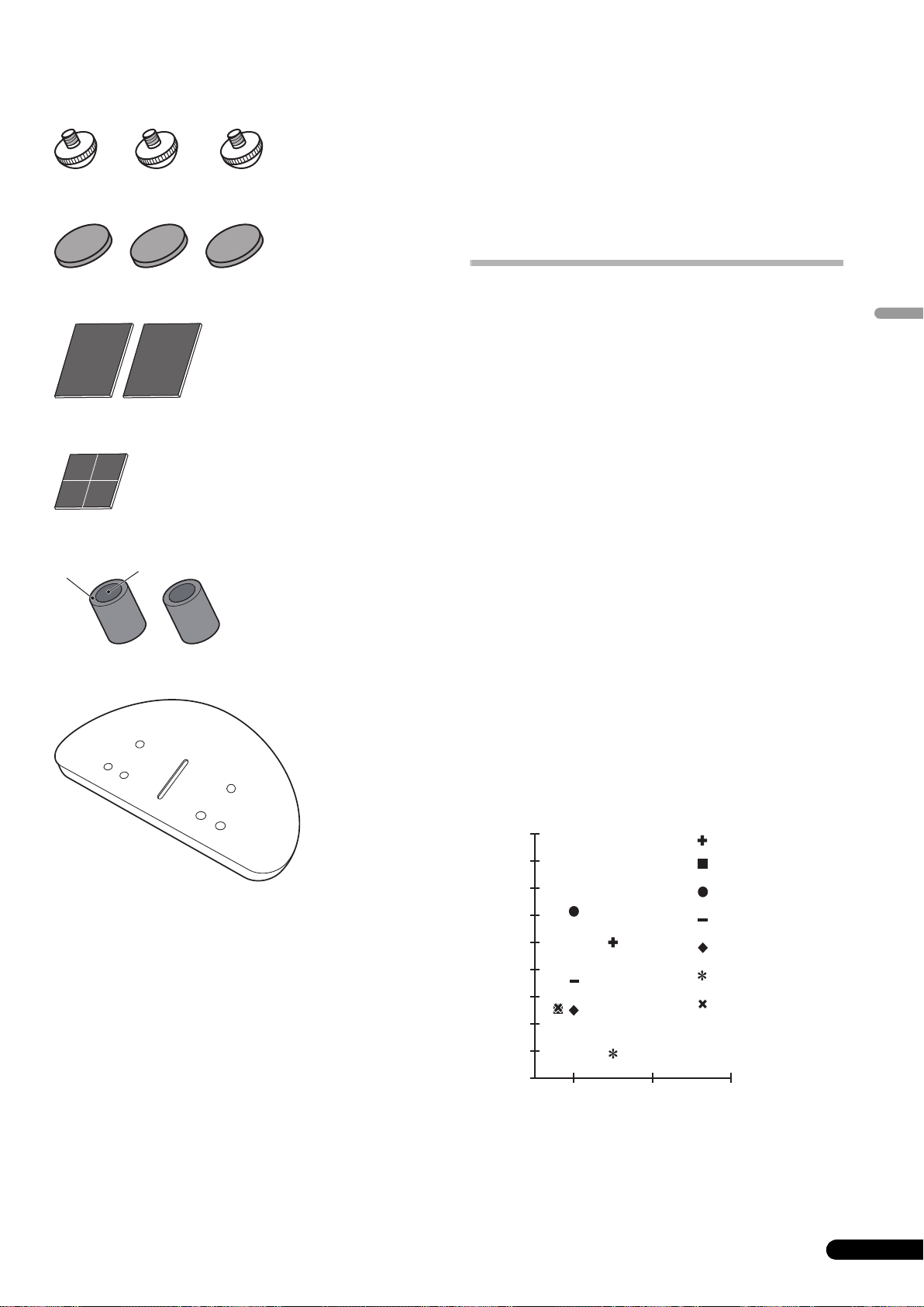
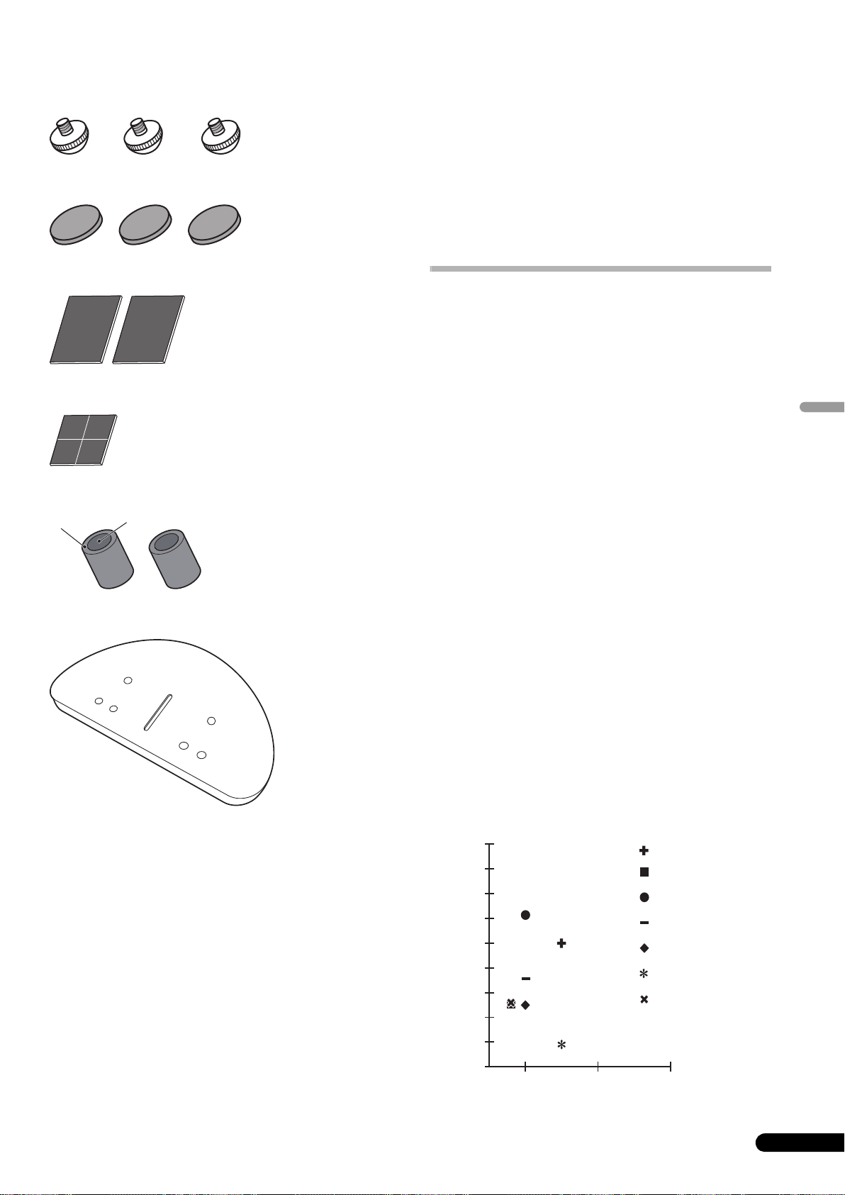
What’s in the box
Spikes x 3
Cork pads x 3
Large non-skid pads x 2
Small non-skid pads x 4
A
Foam plugs (A,B) x 2
B
English
For U.S. model
Speaker base x 1
Washers x 2
Spring washer x 1
Screw (M5 x L40) x 1
Screws (M6 x L35) x 6
For European model
Grille x 1
Operating instructions
3
En
Page 4
About the EX series
The EX series, incorporating the abundant technological know-how behind Pioneer’s flagship TAD speaker series, was developed
with the goal of creating the ultimate speaker possible in its price range.
The design and production of the EX series result from an international effort that represents the finest in Pioneer’s speaker technology.
Bass Drivers
Technology behind the S-8EX
CST
The core driver of the system is the Coherent Source Transducer
(CST), which draws on the technology used in TAD. The tweeter
diaphragm is mounted concentrically within the apex of the
midrange cone and provides a point source of sound from
400 Hz to 100 kHz. The CST ensures a perfect spectral balance
between the direct and reflected sounds that arrive at the
listener’s ears, providing a more consistent sound throughout the
listening room and improved imaging capability.
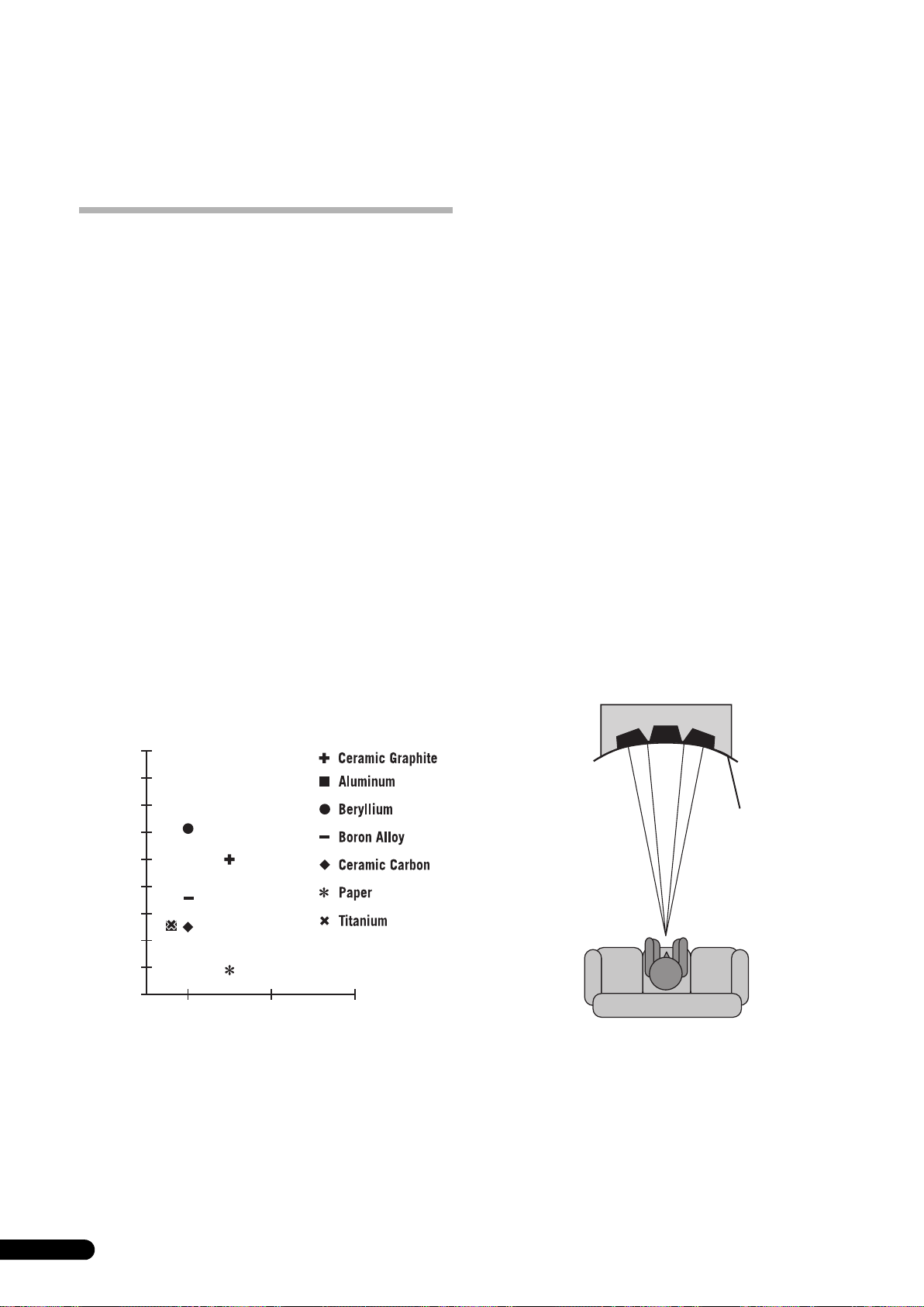
Ceramic Graphite Diaphragm
The CST’s tweeter features a ceramic graphite diaphragm that
provides top-level strength and dampening characteristics that
are practically unrivaled by any other available materials currently
used in high-end audio speaker systems. Ceramic graphite’s
lightness and exceptional strength combine to create speakers
whose diaphragm resonance can be pushed far beyond their
audible range.
The bass driver pictured below serves as the foundation of the
S-8EX speaker system. The driver’s strength is the result of the
Aramid/Carbon composite material, originally created during the
development of the S-1EX, that is used in its diaphragm. Pioneer’s
exclusive LDMC magnetic circuit technology has been
incorporated in order to preserve linearity from low to high output
levels and minimize distortion.
Bass Enclosure Construction
The unique form of the S-8EX is based upon logical necessity. In
order to synchronize the arrival time of sound from the CST and
the two bass drivers, each driver is mounted upon a baffle that
serves to create a highly delicate curve known as the “precision
curve” (see illustration below). Made of up to 65 mm thick MDF
(Medium Density Fiberboard), this baffle is, moreover, strong
enough to contain the force of the drivers. Additionally, the bass
port has been carved out of an extremely thick block of MDF,
resulting in the reduction of wind noise for clear, deep bass.
Velocity (m/s)
18 000
16 000
14 000
12 000
10 000
8 000
6 000
4 000
2 000
0
0.005 0.015
0.025
Inner Loss
Magnesium Alloy Diaphragm
The CST’s midrange features a magnesium alloy diaphragm
whose characteristic lightness and high inner loss provide
excellent transience and minimal coloration of midrange sounds.
Precision curve
4
En
Page 5

Crossover Networks
The crossover networks use only the finest components. Air cored
coils, noninductive resistors, and film capacitors in the signal path
are all carefully chosen and optimized for the CST driver to provide
the greatest transparency to the signal. The bass drivers use
silicon steel plate core inductors that minimize distortion and loss
during energy transfer. All components are connected directly to
their respective wiring materials, instead of a printed circuitboard, allowing for minimal loss and maximum performance.
Collaboration with Air Studios
Since its establishment by George Martin in 1969, London,
England’s Air Studios has earned unequivocal respect from
scores of artists who recognize it as the world’s premier recording
studio. The Air Studios seal that was awarded to the S-8EX
indicates that these speakers are capable of producing the highquality sound demanded by the world’s top-class sound creators.
English
En
5
Page 6
Installation and Placement
Using the furnished speaker base
How to install
Select a desired installation setup from the following.
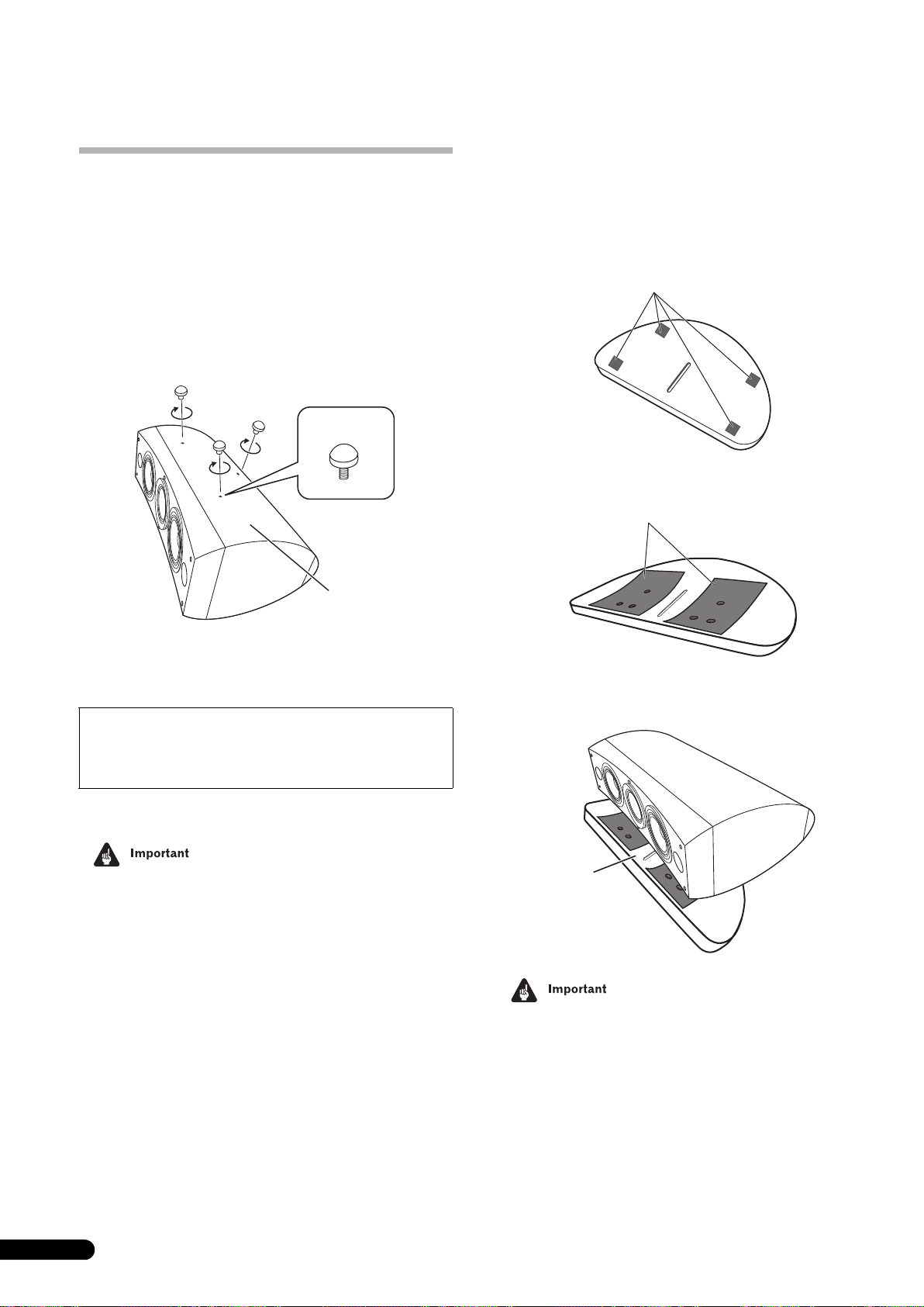
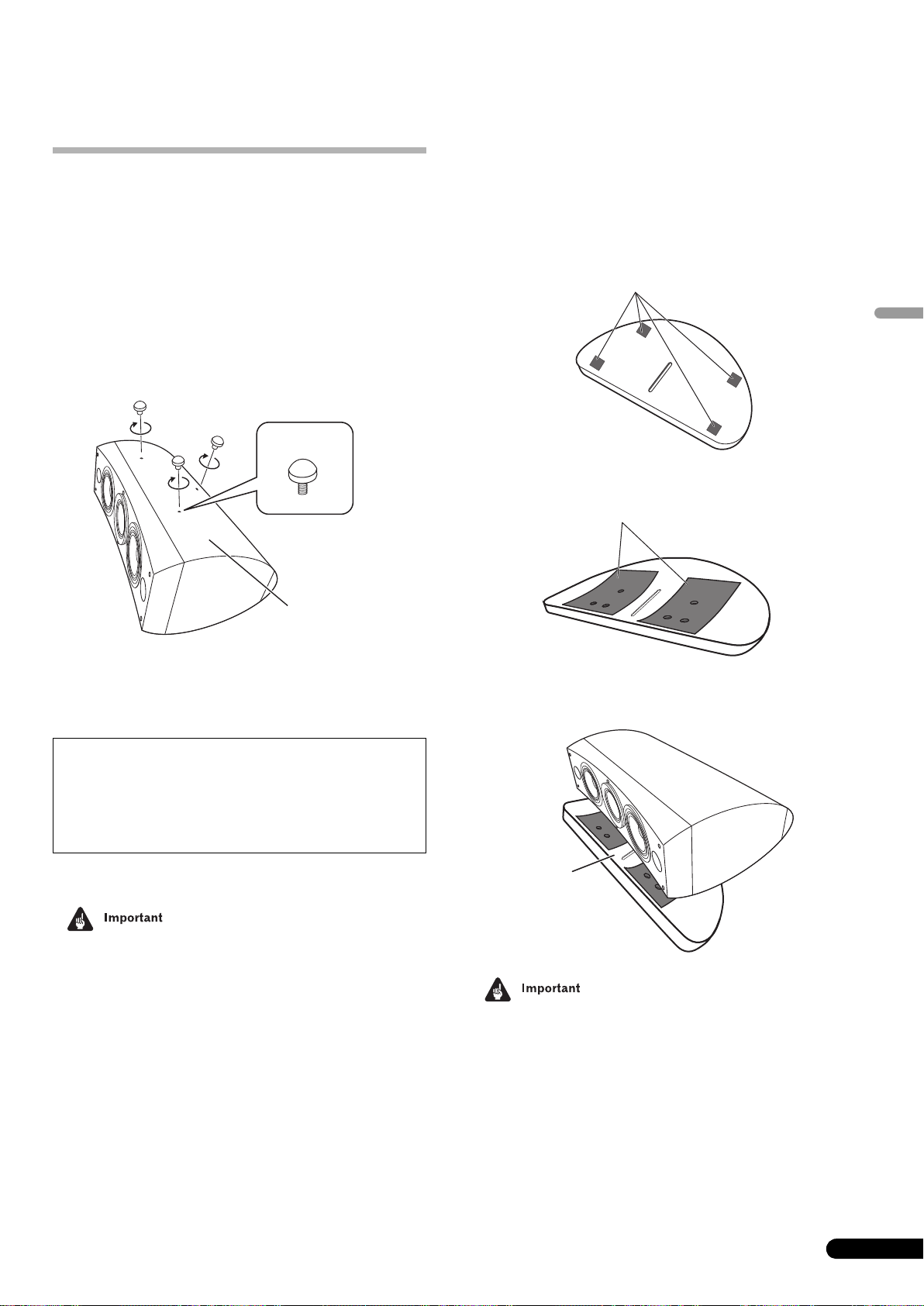
When installing directly on the floor
Use the furnished spikes when installing the speaker directly on a
floor surface.
Installation
1 Twist the spikes into the threads of the three threaded
metal inserts (M6) embedded in the bottom of the speaker,
and screw down securely.
Spike
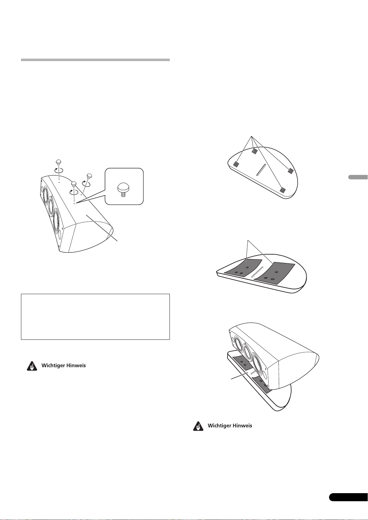
When using the furnished speaker base, the use of the furnished
spikes is not required.
Installation
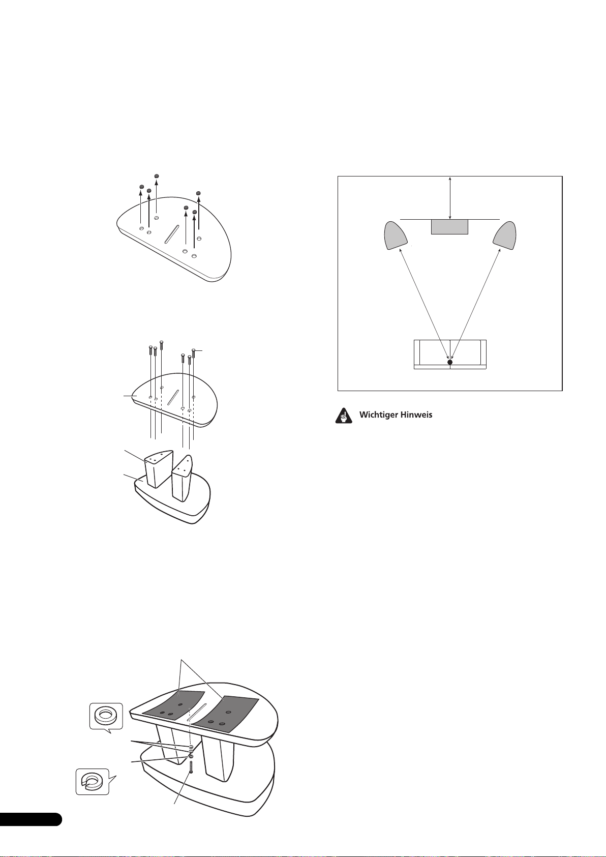
1 Affix the furnished non-skid pads (small) to the four
locations on the bottom of the base.
2 Affix the furnished non-skid pads (large) to the two
places on the top surface of the speaker base.
Small non skid-pads
rge non-skid pads
La
Bottom of
speaker
2 Set the cork pads in the positions where the points of the
three spikes will strike when the speaker is set down.
3 Set the speaker on top of the cork pads.
If you do not use the cork pads when placing the
speakers, the spikes may cause damage to the floor. If
you plan on using the spikes we highly recommend to
use the cork pads.
• As this unit weighs some 28 kg, it is very dangerous to try and
set the spike nut while tilting the speaker. Be sure to place the
unit on a soft area (such as a blanket) so that it does not
damage the floor, and carry out the installation with at least
two people.
3 Place the speaker on top of the base.
Use of the furnished speaker base allows fine adjustment of
the speaker angle.
Speaker
base
• When using the furnished speaker base, do not fix the speaker
in position with screws. The speaker may fall and cause injury.
6
En
Page 7
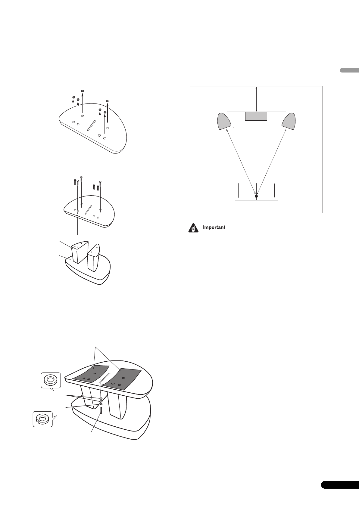
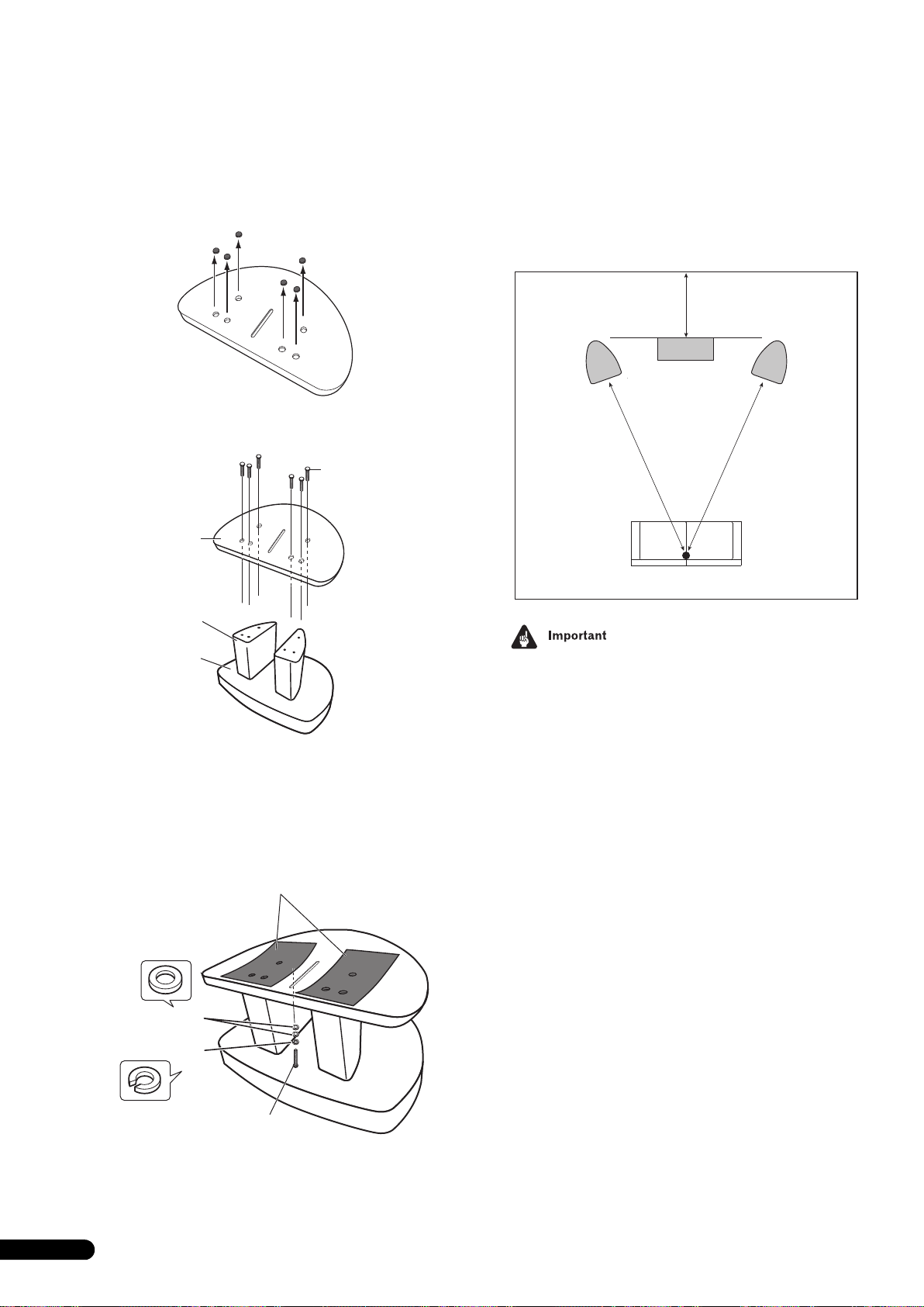
Using the Pioneer Speaker Stand CP-7EX
To use the CP-7EX stand, the furnished speaker base needs to be
attached to the stand stems of the CP-7EX. Assemble the stands
as shown below.
Installation
1 Remove the packing material from the countersunk
screw holes in the speaker base.
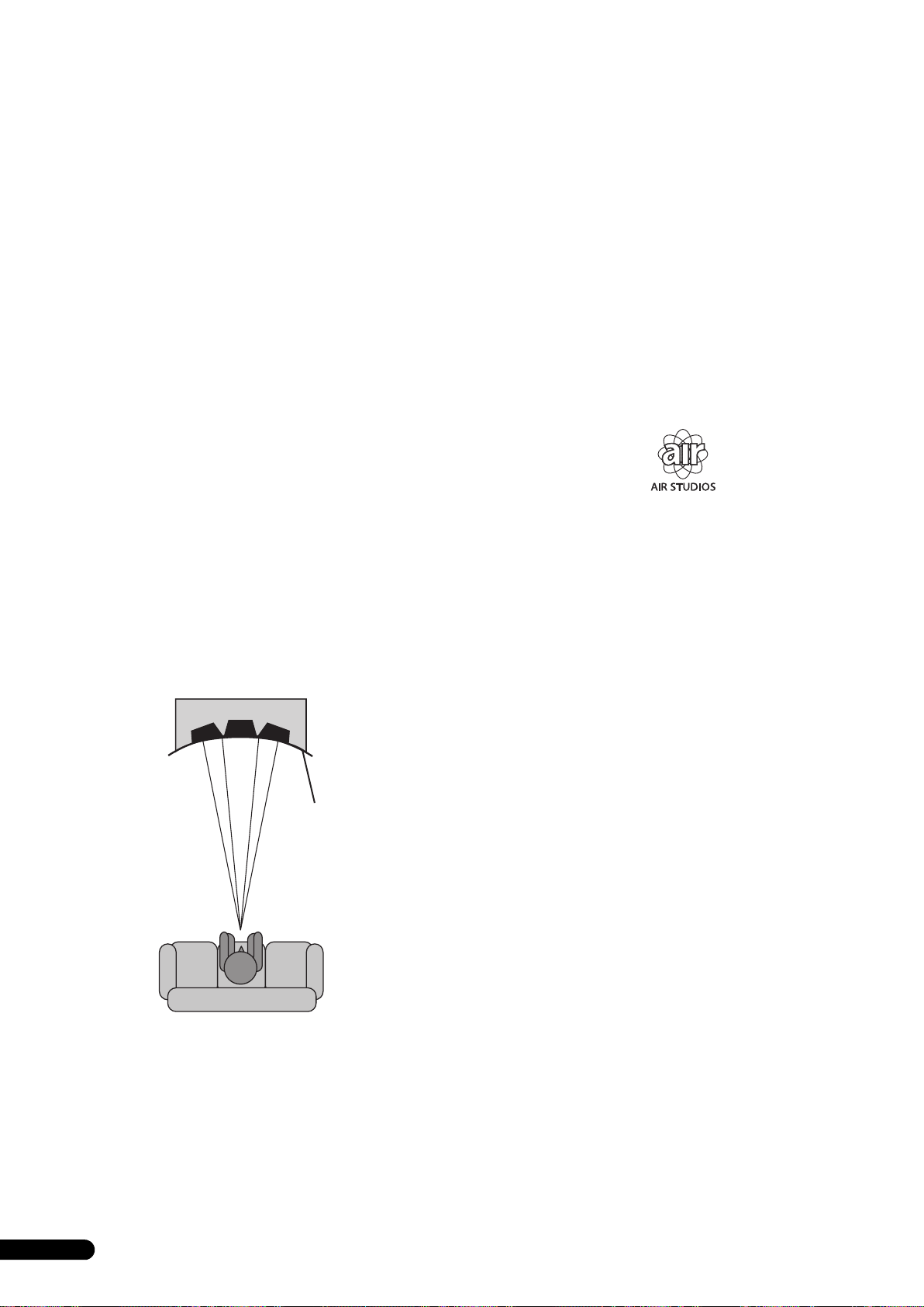
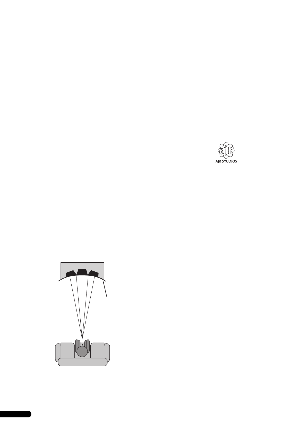
Choosing Where To Place The Speaker Systems
Placement within the listening room will have a great impact upon
the total performance of the S-8EX speaker system in terms of
bass performance, tonal accuracy, and imaging. All rooms are
different and so this section is intended as a guide only.
Experimentation in your room will yield optimum results.
Use the graphic below as a guide to determine optimal speaker
placement.
30 cm to 60 cm
English
2 Attach the speaker base to the stand stems of the CP-7EX.
Use only the furnished screws (M6 x L35).
Screws (M6 x L35)
Speaker
base
Stand stems
Stand base
CP-7EX
Front
speaker
.
Front
speaker
Center speaker
Listening position
• Do not place the speaker where it will be in direct sunlight, and
avoid positioning it near heaters and air conditioners. Doing
so may cause warping and discoloration of the speaker
cabinet and damage to the speaker.
• Pioneer assumes no liability whatsoever for damages
resulting from assembly, improper mounting, insufficient
reinforcement, misuse of the product, acts of nature, etc.
3 Affix the non-skid pads (large).
4 Using the furnished screws (M5 x L40), spring washer and
washer, fasten the speaker to the stand.
To help ensure the speaker from falling, use only the provided
screws to fasten the speaker system to the speaker stand. For
details, consult the instructions provided with the CP-7EX
speaker stand.
Large non-skid pads
Washers
Spring washer
Screw (M5 x L40)
En
7
Page 8

Connections
T
Connecting to an amplifier
This speaker does not include speaker cables used for connecting
to an amplifier. Take the following factors into consideration when
choosing speaker cables so that you can get the most from your
speaker system:
• Use heavy-gauge speaker cable if possible, and keep the
cables to the minimum necessary length.
• Cables have differing characteristics. Keep this in mind when
using any cable.
• Select cables with as little resistance as possible, and make
sure the cables to the speaker terminals and amp are firm and
secure.
CAUTION
hese speaker terminals carry HAZARDOUS LIVE
voltage. To prevent the risk of electric shock when
connecting or disconnecting the speaker cables,
disconnect the power cord before touching any
uninsulated parts.
D3-4-2-2-3_A_En
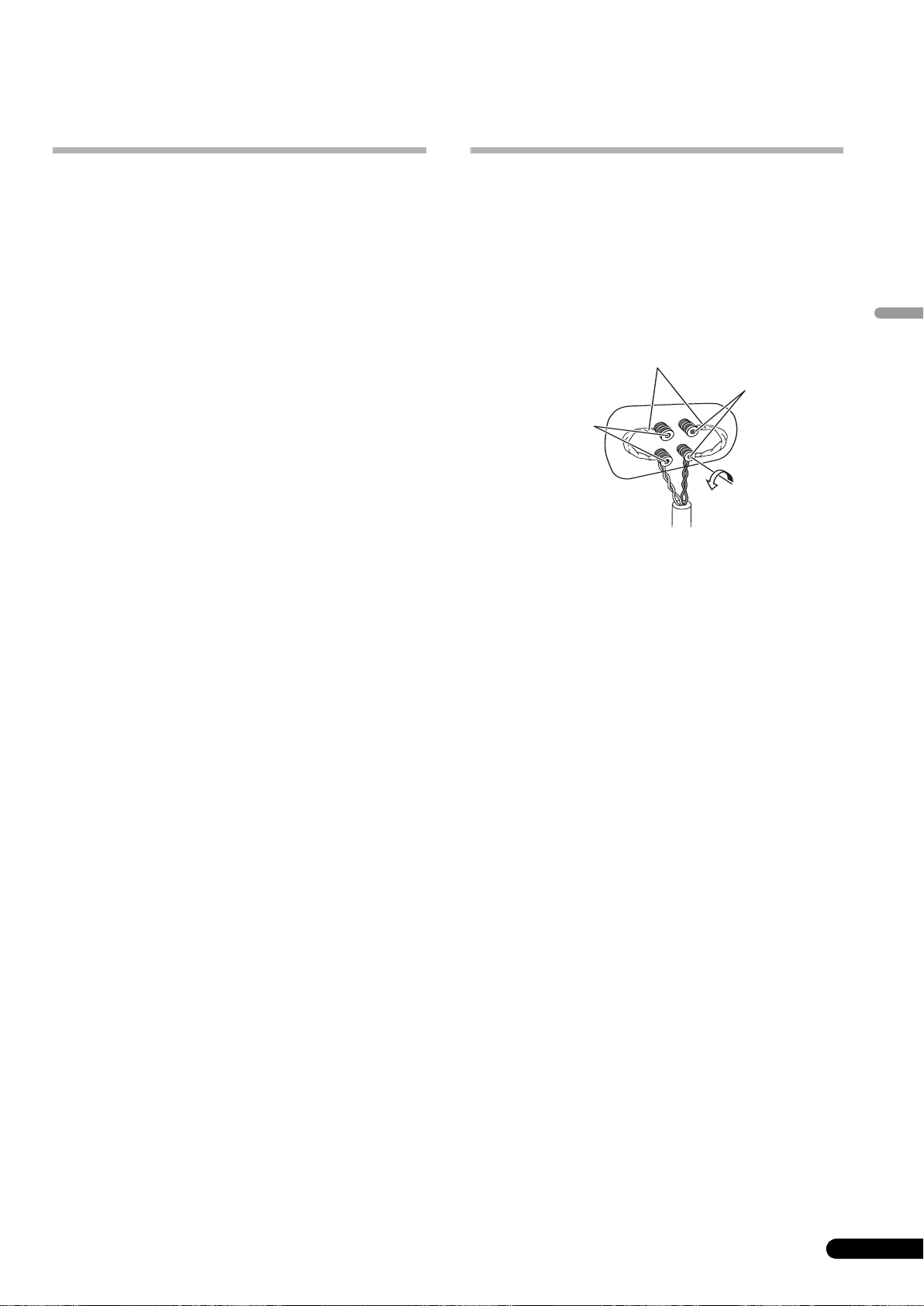
Connecting the cables
1 Switch off the power to your amplifier.
2 Connect the speaker cables to the input terminals (lower)
on the back of the speaker. For input terminal polarity, red is
positive (+) and black is negative (–).
3 Connect the other ends of the cables to the amp’s
speaker output terminals (for more details, refer to your amp
instruction manual).
Short bar connectors
Red terminal (+)
Black terminal
(–)
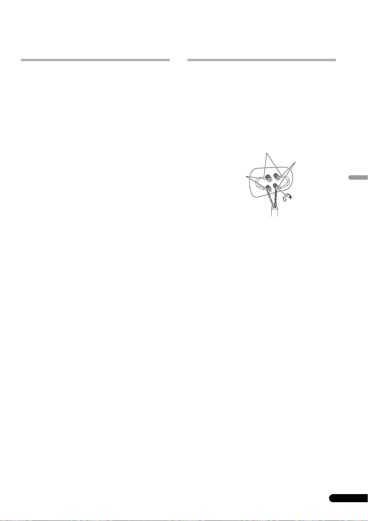
• Grasp the cap knobs on the lower input terminals and rotate
them to the left (counter-clockwise), insert the speaker cable
wires into the holes in the terminal posts, then tighten the
knobs to secure the short bar as well as the wires.
• You can also connect the speaker’s terminals with a banana
plug. When using a banana plug, be sure to remove the cap at
the tip of the input terminal.
• After connecting the plugs, pull lightly on the cables to make
sure that the ends of the cables are securely connected to the
terminals. Poor connections can create noise and
interruptions in the sound.
• If the cables’ wires happen to be pushed out of the terminals,
allowing the wires to come into contact with each other, it
places an excessive additional load on the amp. This may
cause the amp to stop functioning, and may even damage the
amp.
8
En
Page 9
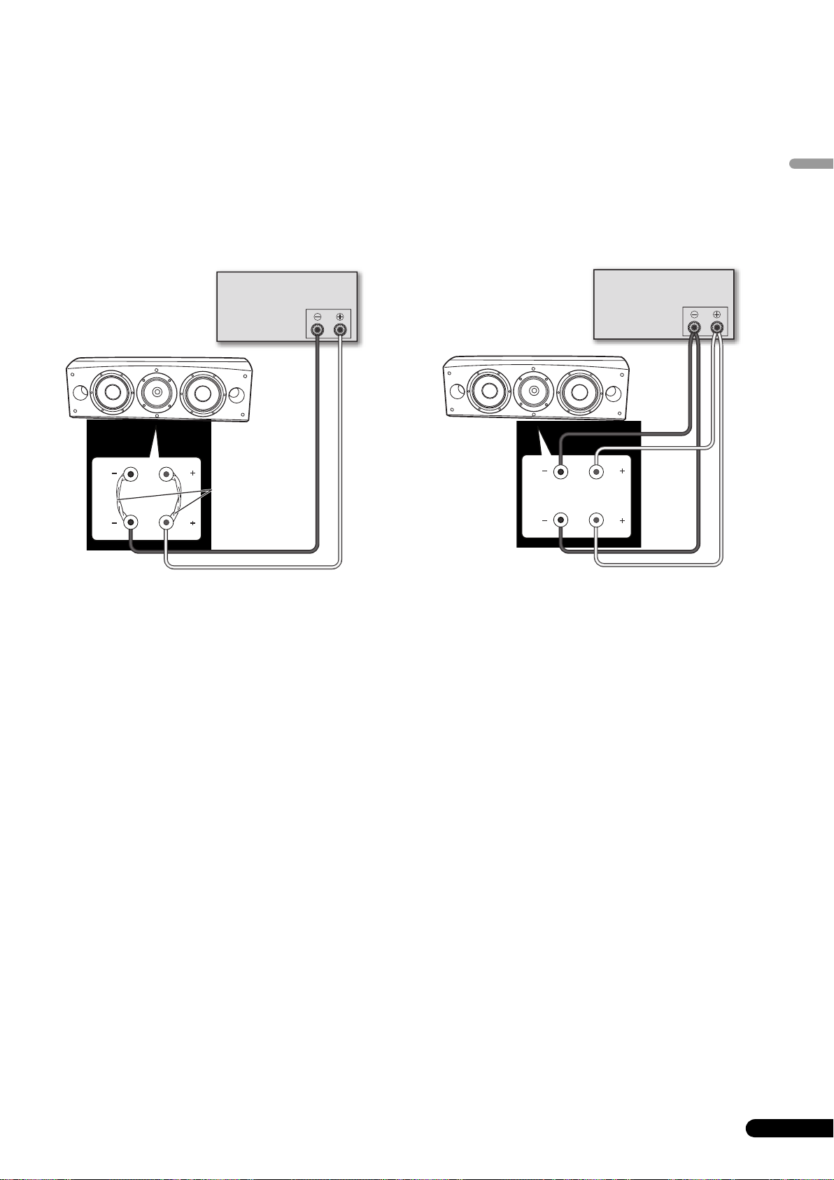
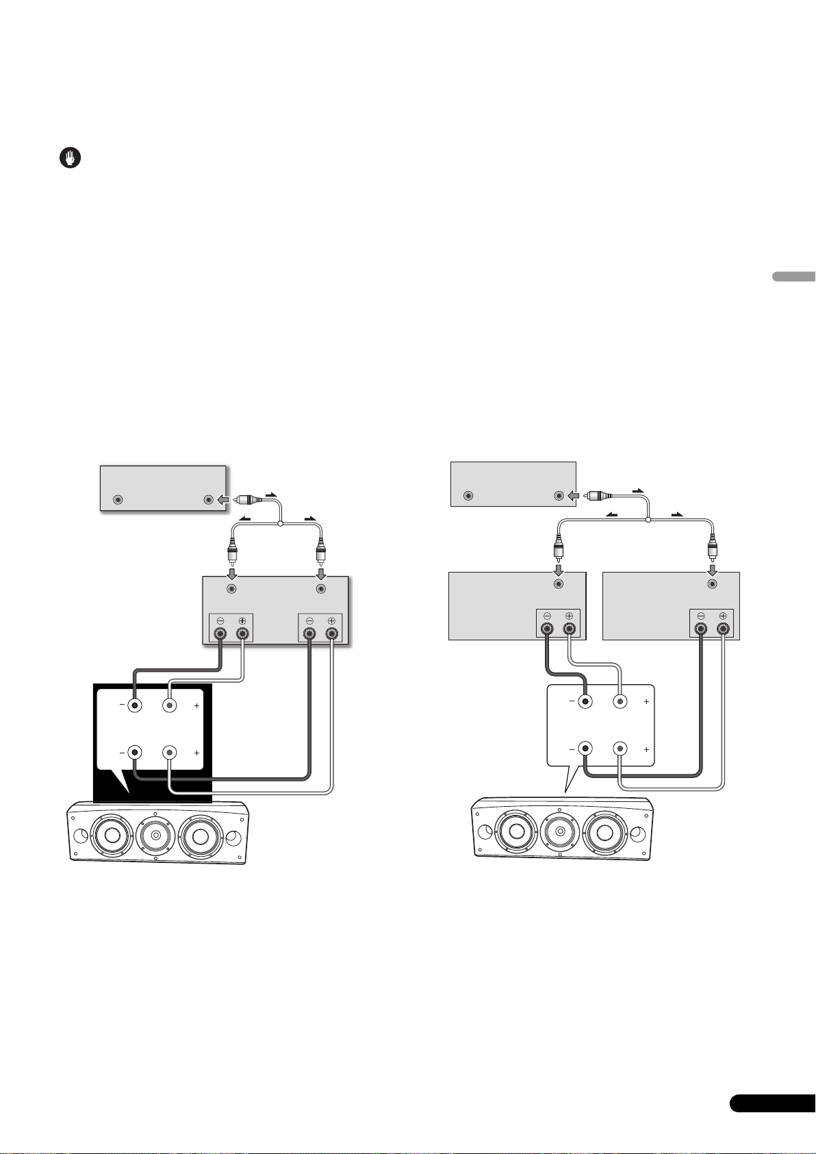
Single-Wire Connections
For single-wire connections, connect the mid-to-high- and lowfrequency sections of the crossover network with the shorting link
that was included with this unit, then connect the (+) wire from
your amplifier to either red binding post and the (–) wire from your
amplifier to either black binding post, as shown in below.
Bi-Wire Connections
In a bi-wiring connection, you independently plug in the speaker
systems running from the amp to their respective high- and lowfrequency plugs. This results in the CST driver and bass drivers
being independently connected directly to the amplifier, offering
you the freedom to optimize the cable type for each of the drivers.
Connect one set of wires to the bottom set of binding posts (bass
driver-specific network). Then connect a second set of wires to the
top binding posts (CST-specific network). Next, connect both sets
of wires to the appropriate terminals on your amplifier. Take care
to connect both (+) wires to the (+) amplifier terminals and both
(–) wires to the (–) amplifier terminals, as shown below.
English
(Only one channel shown)
Amplifier (rear)
Speaker
HF
HF
Shorting link
connection
LF
LF
Speaker (rear): Input panel
SPEAKERS OUTPUT
(Only one channel shown)
Amplifier (rear)
SPEAKERS OUTPUT
Speaker
HF
LF
HF
LF
Speaker (rear): Input panel
En
9
Page 10
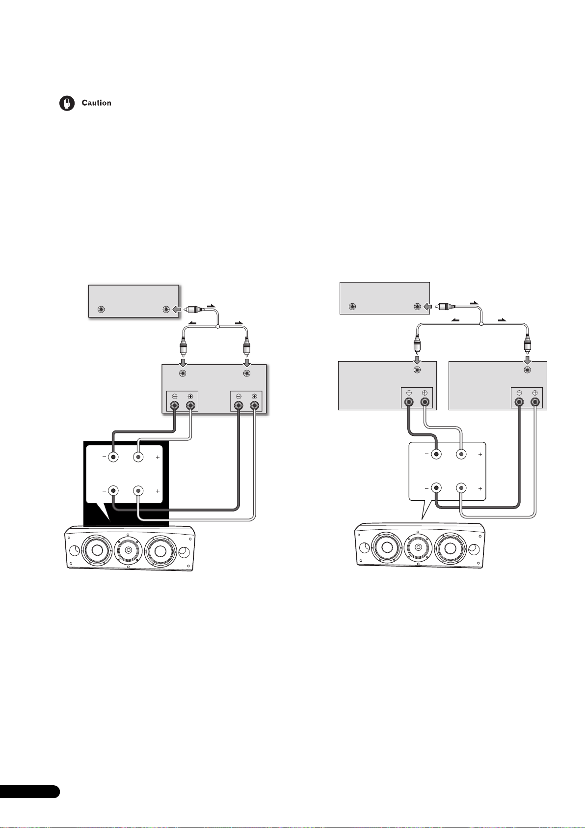
Bi-Amplification Connections
Bi-Amplification allows the best performance when using dedicated amplifiers for low- and mid-to-high-frequency sections.
There are two possible configurations, commonly referred to as horizontal and vertical bi-amping.
Remove the shorting links before connecting speaker cables in bi-amplifications connections.
Failure to do so may result in damage to your amplifiers.
Vertical Bi-Amping
With this configuration, identical stereo amplifiers are used for
each speaker system. One channel of each amplifier drives the
low frequency section and the other channel drives the high
frequency section, as shown below.
Connect one set of wires and amplifier channel to the bottom set
of binding posts (bass driver-specific network).
Then connect a second set of wires and the other amplifier
channel to the top binding posts (CST-specific network).
Take care to connect both (+) wires to the (+) amplifier terminals
and both (–) wires to the (–) amplifier terminals.
Pre-amp (rear)
OUTPUT
(Only one channel shown)
OUTPUT
(Commerciallyavailable Y-adaptor)
Power amp
INPUT
(rear)
SPEAKERS OUTPUT
Ch.1 Ch.2
INPUT
Horizontal Bi-Amping
With this configuration, you may use different stereo amplifiers for
the low- and mid-to-high-frequency sections of the speaker system
(e.g., tube amplifiers for high frequency and solid state for low
frequency). Each channel of one amplifier drives the lowfrequency section of each speaker system and each channel of
the other amplifier drives the mid-to-high-frequency section, as
shown below.
This method requires that both amplifiers have the same gain;
otherwise an imbalance will be heard between the low- and midto-high-frequency reproduction from the speaker system. If in
doubt, please consult your local dealer.
Pre-amp (rear)
OUTPUTOUTPUT
(Only one channel shown)
Power amp (rear)
(High frequency)
SPEAKERS OUTPUT
(Commercially-available
Y-adaptor)
INPUT
Power amp (rear)
(Low frequency)
(Only one channel shown)(Only one channel shown)
INPUT
SPEAKERS OUTPUT
HF
LF
Speaker
HF
Speaker (rear):
Input panel
LF
Speaker (rear):
Input panel
HF
LF
Speaker
HF
LF
10
En
Page 11
Other Information
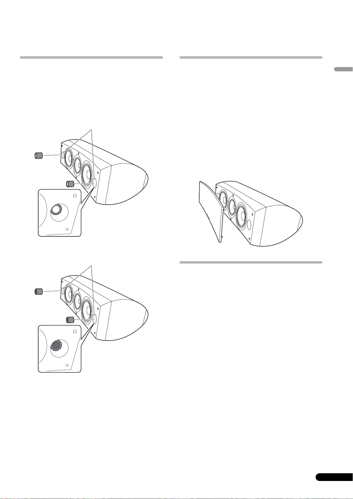
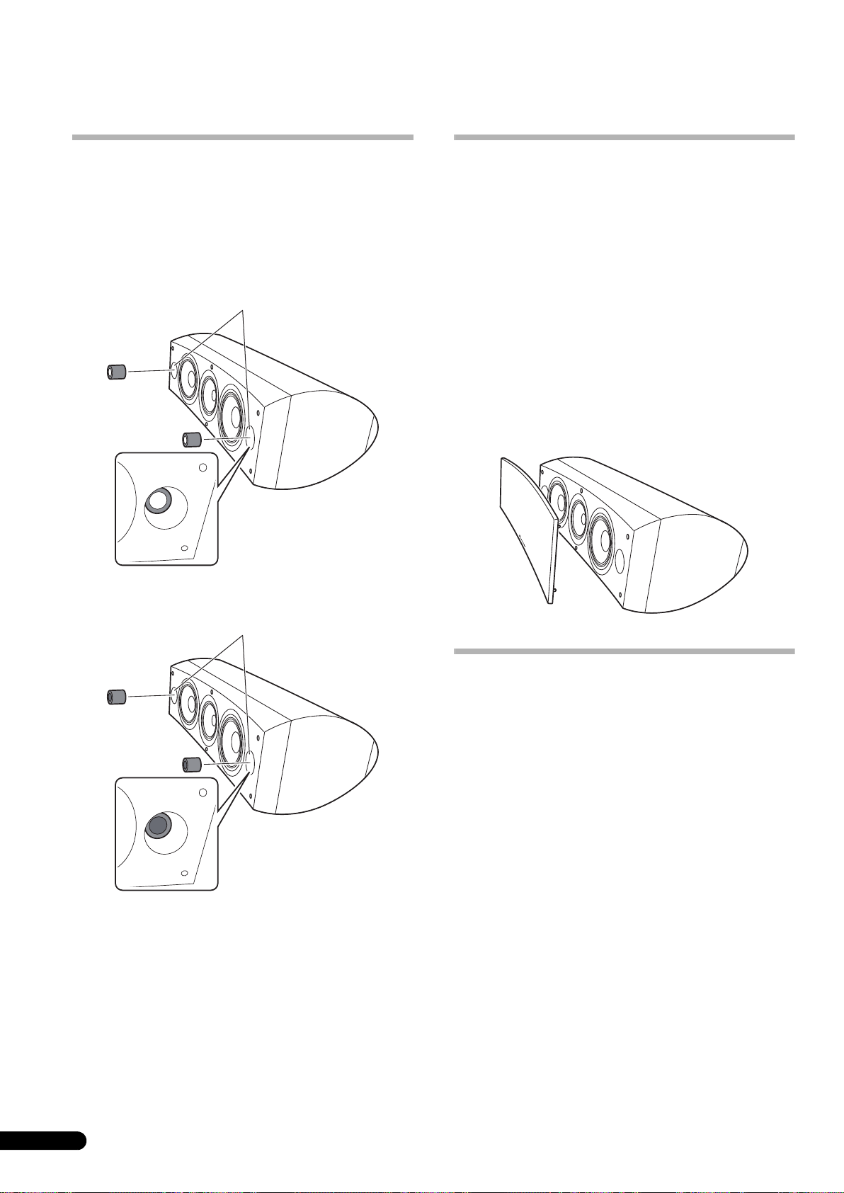
Using the foam plugs
This unit is furnished with foam plugs that are useful for adjusting
the volume of bass sound. To use, place the foam plugs gently into
the bass reflex ports on either side of the speaker. Insert either
foam plug A alone, or both foam plugs A and B to achieve the
desired sound.
Using foam plugs A only
Bass reflex ports
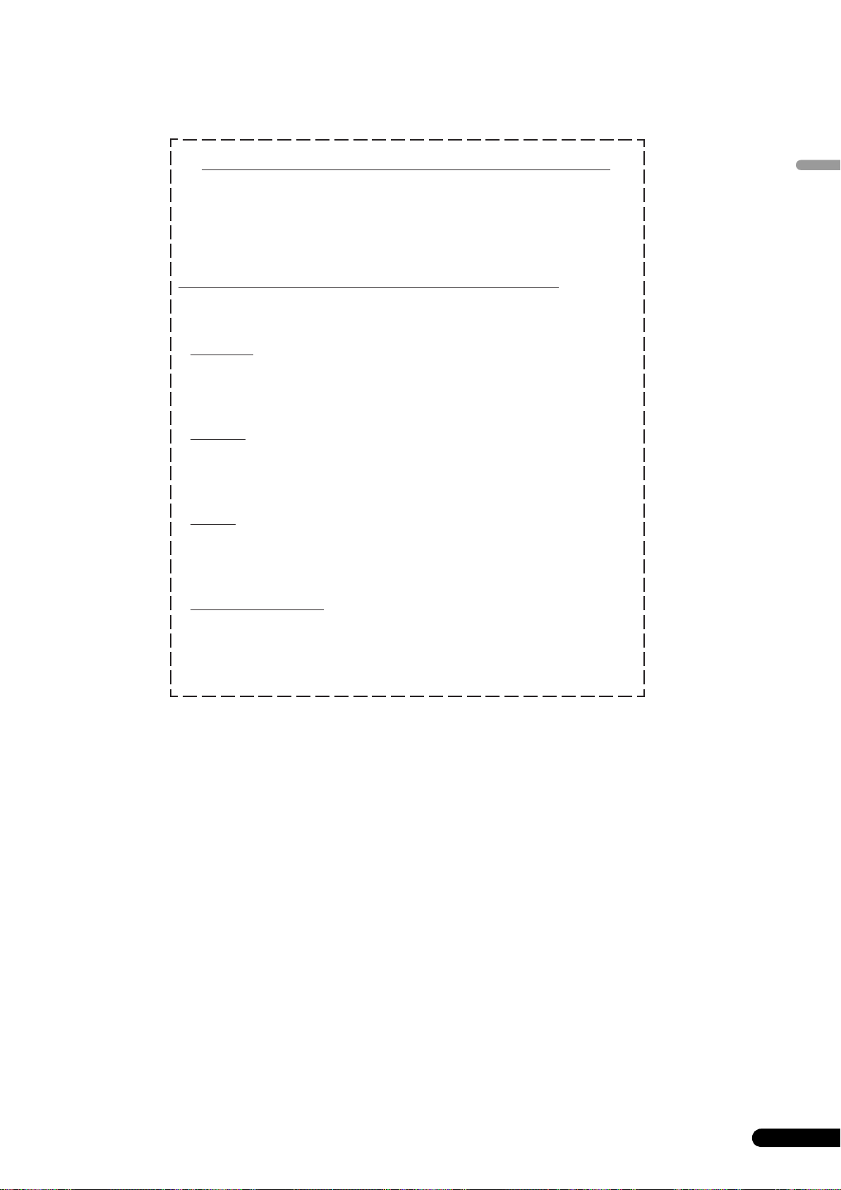
Attaching/Removing the Grille Cover
This speaker system comes with grille covers which may be
attached and removed by:
1 To attach the grille cover, line up the holes on the speaker
with the inserts on the grill, and press firmly.
2 To remove the grille cover, grasp the upper and lower
edges of the grille cover at the left side by your hands and
gently pull toward you to separate the left part of the grille
cover from the speaker.
3 Then move your hands to the middle of the grille cover
and again gently pull the upper and lower edges toward you
to separate the middle section.
4 Finally, grasp the upper and lower edges of the grille
cover at the right side and gently pull toward you to
separate the remaining part of the grille cover from the
speaker.
English
Using both foam plugs A and B
Bass reflex ports
Cleaning the speaker cabinet
With normal use, wiping with a dry cloth should be sufficient to
keep the cabinet clean. If necessary, clean with a cloth dipped in
a neutral cleanser diluted five or six times with water, and wrung
out well. Do not use furniture wax or cleansers.
Never use thinners, benzine, insecticide sprays or other chemicals
on or near this unit since these will corrode the surfaces.
11
En
Page 12

Specifications
Enclosure . . . . . . . . . . . . . . . . . . . . . . . . Bass-reflex floorstanding type
Configuration . . . . . . . . . . . . . . . . . . . . . . . . . . . . . . . . . . . . . . . . . .3-way
Woofer . . . . . . . . . . . . . . . . . . . . . . . . . . . . . 16 cm (6
Mid tweeter . . . . . . . . .14 cm (5
Impedance . . . . . . . . . . . . . . . . . . . . . . . . . . . . . . . . . . . . . . . . . . . . . 6 Ω
Frequency response. . . . . . . . . . . . . . . . . . . . . . . . . . . .34 Hz to 100 kHz
Sensitivity . . . . . . . . . . . . . . . . . . . . . . . . . . . . . . . . . . . . 88.5 dB (2.83 V)
Maximum input power. . . . . . . . . . . . . . . . . . . . . . . . . . . . . . . . . . 160 W
Exterior dimensions . . . . . . . 723 (W) mm x 263 (H) mm x 387 (D) mm
Weight . . . . . . . . . . . . . . . . . . . . . . . . . . . . . . . . . . . . 28 kg (61 lbs 12 oz.)
1
/2 inch) cone/3 cm (1 3/16 inch) dome
1
28
/2 (W) in. x 10 3/8 (H) in. x 15 1/4 (D) in.
(magnetically shielded)
5
/16 inch) cone x 2
Specifications and design subject to possible modification
without notice, due to improvements.
Magnetic shielding
This speaker system is magnetically shielded. However,
depending on the installation location, color distortion may occur
if the speaker system is installed extremely close to the screen of
a television set.
If this happens, turn off the television, then turn it on again after
15 min to 30 min. If the problem persists, place the speaker system
away from the television set.
Supplied accessories
Spikes . . . . . . . . . . . . . . . . . . . . . . . . . . . . . . . . . . . . . . . . . . . . . . . . . . . .3
Cork pads . . . . . . . . . . . . . . . . . . . . . . . . . . . . . . . . . . . . . . . . . . . . . . . . .3
Large non-skid pads. . . . . . . . . . . . . . . . . . . . . . . . . . . . . . . . . . . . . . . . .2
Small non-skid pads. . . . . . . . . . . . . . . . . . . . . . . . . . . . . . . . . . . . . . . . .4
Foam plugs (A,B) . . . . . . . . . . . . . . . . . . . . . . . . . . . . . . . . . . . . . . . . . . .2
Speaker base . . . . . . . . . . . . . . . . . . . . . . . . . . . . . . . . . . . . . . . . . . . . . .1
Washers . . . . . . . . . . . . . . . . . . . . . . . . . . . . . . . . . . . . . . . . . . . . . . . . . .2
Spring washer. . . . . . . . . . . . . . . . . . . . . . . . . . . . . . . . . . . . . . . . . . . . . .1
Screw (M5 x L40) . . . . . . . . . . . . . . . . . . . . . . . . . . . . . . . . . . . . . . . . . . .1
Screws (M6 x L35). . . . . . . . . . . . . . . . . . . . . . . . . . . . . . . . . . . . . . . . . . .6
Grille . . . . . . . . . . . . . . . . . . . . . . . . . . . . . . . . . . . . . . . . . . . . . . . . . . . . .1
Operating instructions
is a trademark placed on a product with Pioneer’s Phase
Control technology. This technology enables high-grade sound
reproduction through each component by improving overall
phase matching.
Published by Pioneer Corporation.
Copyright © 2008 Pioneer Corporation.
All rights reserved.
12
En
Page 13
AFTER-SALES SERVICE FOR PIONEER PRODUCTS
Please contact the dealer or distributor from where you purchased the
product for its after-sales service (including warranty conditions) or any
other information. In case the necessary information is not available,
please contact the Pioneer’s subsidiaries (regional service headquarters)
listed below:
PLEASE DO NOT SHIP YOUR PRODUCT TO THE COMPANIES at the
addresses listed below for repair without advance contact, for these
companies are not repair locations.
AMERICA
PIONEER ELECTRONICS SERVICE, INC.
P.O. BOX 1760, LONG BEACH, CA 90801-1760, U.S.A.
CUSTOMER SERVICE HOTLINE : 1 (800) 421-1404
EUROPE
PIONEER EUROPE NV
EUROPEAN SERVICE DIVISION
HAVEN 1087, KEETBERGLAAN 1, B-9120 MELSELE, BELGIUM
ASEAN
PIONEER ELECTRONICS ASIACENTRE PTE. LTD.
SERVICE DEPARTMENT
253, ALEXANDRA ROAD #04-01 SINGAPORE 159936
English
JAPAN AND OTHERS
PIONEER CORPORATION (HEAD OFFICE)
CUSTOMER SUPPORT CENTER
4-1, MEGURO 1-CHOME, MEGURO-KU, TOKYO 153-8654 JAPAN
S016_A_En
13
En
Page 14

Nous vous remercions d’avoir acheté ce produit Pioneer.
Veuillez lire attentivement ce mode d’emploi de manière à pouvoir utiliser votre modèle correctement.
Après avoir lu ces explications, conservez-les en lieu sûr pour éventuellement les consulter plus tard.
Sommaire
Avant de commencer
Contenu de l’emballage
A propos de la série EX
Technologies à l’appui du S-8EX . . . . . . . . . . . . . . . . . . . . . . . . . . . 3
CST. . . . . . . . . . . . . . . . . . . . . . . . . . . . . . . . . . . . . . . . . . . . . . . . 3
Diaphragme en graphite céramique. . . . . . . . . . . . . . . . . . . . . . . 3
Diaphragme en alliage de magnésium. . . . . . . . . . . . . . . . . . . . . 4
Haut-parleurs de graves . . . . . . . . . . . . . . . . . . . . . . . . . . . . . . . . 4
Construction du boîtier des graves . . . . . . . . . . . . . . . . . . . . . . . . 4
Circuits séparateurs de fréquences . . . . . . . . . . . . . . . . . . . . . . . 4
Collaboration avec Air Studios . . . . . . . . . . . . . . . . . . . . . . . . . . . 4
Installation et placement
Méthode d’installation . . . . . . . . . . . . . . . . . . . . . . . . . . . . . . . . . . 5
Pour une installation directement sur le plancher . . . . . . . . . . . . 5
Utilisation de la base d’enceinte fournie. . . . . . . . . . . . . . . . . . . . 5
Utilisation du Socle d’enceinte Pioneer CP-7EX . . . . . . . . . . . . . . 6
Choix d’un emplacement pour les enceintes acoustiques . . . . . . 6
Connexions
Branchement à un amplificateur . . . . . . . . . . . . . . . . . . . . . . . . . . 7
Câblage. . . . . . . . . . . . . . . . . . . . . . . . . . . . . . . . . . . . . . . . . . . . . . 7
Mono-câblage. . . . . . . . . . . . . . . . . . . . . . . . . . . . . . . . . . . . . . . . 8
Bi-câblage . . . . . . . . . . . . . . . . . . . . . . . . . . . . . . . . . . . . . . . . . . 8
Câblage pour bi-amplification. . . . . . . . . . . . . . . . . . . . . . . . . . . . 9
Autres informations
Utilisation des bouchons de mousse. . . . . . . . . . . . . . . . . . . . . . . 10
Utilisation des bouchons de mousse A seulement . . . . . . . . . . . 10
Utilisation des bouchons de mousse A et B . . . . . . . . . . . . . . . . 10
Fixation et dépose du couvercle de grille. . . . . . . . . . . . . . . . . . . . 10
Nettoyage du coffret de l’enceinte. . . . . . . . . . . . . . . . . . . . . . . . . 10
Fiche technique . . . . . . . . . . . . . . . . . . . . . . . . . . . . . . . . . . . . . . 11
Avant de commencer
• L’impédance nominale de ces enceintes acoustiques est de
6 Ω. Raccordez ces enceintes à un amplificateur dont
l’impédance de charge va de 6 Ω à 16 Ω (un modèle pour
lequel “6 Ω – 16 Ω” est indiqué sur les bornes de sortie de
haut-parleurs).
Pour éviter d’endommager les enceintes par une surcharge à
l’entrée, observez les précautions suivantes :
• Ne fournissez pas aux enceintes acoustiques une puissance
électrique dépassant l’entrée maximale autorisée.
• Si vous utilisez un égaliseur graphique pour accentuer les
sons dans la plage des hautes fréquences, n’élevez pas trop le
volume de l’amplificateur.
• N’essayez pas de pousser un amplificateur de faible
puissance à produire un volume sonore élevé, car la distorsion
harmonique de l’amplificateur en serait accentuée et vous
pourriez endommager les haut-parleurs.
Précautions installation
• Lors de l’installation de l’appareil, veillez à ce qu’il soit
fermement immobilisé et évitez les endroits d’où il pourrait
tomber et provoquer des blessures lors d’une catastrophe
naturelle, telle qu’un séisme.
• Ne fixez pas les enceintes sur une paroi ou au plafond, car
elles pourraient tomber et provoquer des blessures.
• N’installez pas les enceintes en hauteur, au plafond ou sur
une paroi. Si elle est mal installée, la grille des haut-parleurs
pourrait tomber et provoquer des dégâts, voire des blessures
à des personnes.
• Mettez votre système audiovisuel hors tension et débranchezle, puis consultez le mode d’emploi avant de brancher des
composants. Prenez soin d’utiliser correctement les cordons
de raccordement.
Précautions à l’emploi
• Ne placez pas l’enceinte sur une surface instable, car en
tombant, elle pourrait entraîner des blessures et être
endommagée.
• N’utilisez pas les enceintes pour produire des sons distordus
pendant une longue période, car ceci pourrait provoquer un
incendie.
• Ne montez pas et ne vous asseyez pas sur les enceintes et ne
laissez pas des enfants jouer sur celles-ci.
• Ne posez pas d’objets lourds ou volumineux sur le dessus des
enceintes.
• Ne placez pas d’objets magnétiques tels que des tournevis ou
des pièces en fer près du tweeter ou du médium. Comme ces
haut-parleurs utilisent des aimants puissants, ces objets
pourraient être attirés, provoquant des dégâts aux hautparleurs ou endommageant leur diaphragme.
Si vous souhaitez vous débarrasser de cet appareil, ne le mettez pas à la poubelle avec vos ordures ménagères. Il existe un système de
collecte séparé pour les appareils électroniques usagés, qui doivent être récupérés, traités et recyclés conformément à la législation.
Les habitants des états membres de l’UE, de Suisse et de Norvège peuvent retourner gratuitement leurs appareils électroniques usagés aux
centres de collecte agréés ou à un détaillant (si vous rachetez un appareil similaire neuf).
Dans les pays qui ne sont pas mentionnés ci-dessus, veuillez contacter les autorités locales pour savoir comment vous pouvez vous débarrasser
de vos appareils.
Vous garantirez ainsi que les appareils dont vous vous débarrassez sont correctement récupérés, traités et recyclés et préviendrez de cette façon
les impacts néfastes possibles sur l’environnement et la santé humaine.
2
Fr
K058_A_Fr
Page 15
Contenu de l’emballage
A
B
Pointes de découplage x 3
A propos de la série EX
Tirant parti du riche savoir-faire technologique qui a permis
de créer la série-phare d’enceintes acoustiques TAD de
Pioneer, la série EX a été mise au point afin de proposer ce
qu’il y a de mieux dans cette catégorie de prix.
Le design et la production de la série EX résultent d’un effort
international qui a fait converger la quintessence des
technologies de Pioneer dans le domaine des haut-parleurs.
Cales en liège x 3
Grands coussinets antidérapants x 2
Petits coussinets antidérapants x 4
Bouchons de mousse (A, B) x 2
Technologies à l’appui du S-8EX
CST
L’excitateur électrostatique au cœur du système est le
Transducteur de Source Cohérent (CST) qui repose sur les
technologies utilisées dans la série TAD. Le diaphragme du
tweeter est installé de façon concentrique au sommet du cône du
médium et il fournit une source ponctuelle de sons, allant de
400 Hz à 100 kHz. Le transducteur CST procure un équilibre
spectral parfait entre les sons directs et réfléchis qui parviennent
aux oreilles de l’auditeur. Il fournit ainsi un son plus homogène
dans toute la salle d’écoute et améliore l’image sonore.
Diaphragme en graphite céramique
Le tweeter du CST est muni d’un diaphragme en graphite
céramique qui procure des caractéristiques idéales de rigidité et
d’amortissement. Elles atteignent un niveau pratiquement
inégalable par les autres matériaux actuellement disponibles pour
les enceintes acoustiques haut de gamme. La légèreté et la
résistance exceptionnelles du graphite céramique s’associent
pour créer des haut-parleurs dont la résonance de diaphragme
peut être poussée bien au-delà de leur plage audible.
Français
Vélocité (m/s)
Base d’enceinte x 1
Rondelles x 2
Rondelle à ressort x 1
Vis (M5 x L40) x 1
Vis (M6 x L35) x 6
Grille x 1
Mode d’emploi
18 000
16 000
14 000
12 000
10 000
8 000
6 000
4 000
Graphite céramique
Aluminium
Beryllium
Alliage de boron
Carbone céramique
Papier
Titane
2 000
0
0,005 0,015 0,025
Pertes internes
3
Fr
Page 16
Diaphragme en alliage de magnésium
Le haut-parleur médium du CST présente un diaphragme en
alliage de magnésium dont la légèreté et la forte perte interne
assurent une excellente transition et une coloration minimale des
sons de la plage moyenne.
Haut-parleurs de graves
Le haut-parleur de graves illustré ci-dessous sert de base à
l’enceinte acoustique S-8EX. La rigidité de sa membrane provient
du matériau composite en aramide/carbone, créé lors de la mise
au point du S-1EX et utilisé dans son diaphragme. La technologie
des circuits magnétiques LDMC, exclusive à Pioneer, a été
intégrée afin de réduire la distorsion et de préserver la linéarité à
tous les niveaux de sortie, des faibles aux puissants.
Construction du boîtier des graves
La forme unique du S-8EX a une fonction bien précise. Afin de
synchroniser les temps d’arrivée des sons provenant du CST et
des deux haut-parleurs de graves, chacun d’eux est installé sur un
baffle qui contribue à créer une courbe très délicate, appelée la
“courbe de précision” (cf. L’illustration ci-dessous). Réalisé en
MDF (Medium Density Fiberboard) d’une épaisseur allant jusqu’à
65 mm, ce baffle est par ailleurs suffisamment rigide pour
contenir la force des hautparleurs. De plus, le port des graves est
découpé dans un bloc extrêmement épais de MDF, ce qui réduit
les bruits de vent et fournit des graves profondes et claires.
Circuits séparateurs de fréquences
Les circuits séparateurs de fréquences n’utilisent que des
composants hors pair. Disposés sur le parcours des signaux, des
bobines à air, des résistances non inductives et des
condensateurs à film ont été choisis et optimisés avec soin de
sorte que le CST puisse procurer la plus grande transparence
possible aux signaux. Les haut-parleurs de graves font appel à des
inducteurs à noyau en plaque d’acier au silicium pour minimiser
la distorsion et les pertes pendant le transfert d’énergie. Tous les
composants sont reliés directement à leurs matériaux de câblage
respectifs et non pas à une carte de circuit imprimé, ce qui
autorise des pertes minimales et des performances maximales.
Collaboration avec Air Studios
Depuis leur fondation à Londres par George Martin en 1969, les Air
Studios d’Angleterre se sont acquis le respect sans aucun
équivoque d’une foule d’artistes qui les considèrent comme les
meilleurs studios d’enregistrement au monde. Le label “Air
Studios” décerné aux S-8EX prouve que ces enceintes
acoustiques sont capables de restituer la haute qualité sonore,
exigée par les ingénieurs du son les plus réputés du monde.
Coube de précision
4
Fr
Page 17
Installation et placement
Méthode d’installation
Sélectionnez un mode d’installation en tenant compte de ce qui
suit.
Pour une installation directement sur le plancher
Utilisez les pointes de découplage fournie pour installer
directement l’enceinte sur un plancher.
Utilisation de la base d’enceinte fournie
A l’emploi du socle d’enceinte fourni, il n’est pas nécessaire
d’utiliser les pointes de découplage fournies.
Installation
1 Fixez les (petits) coussinets antidérapants fournis aux
quatre endroits sur le fond de la base.
Petits coussinets antidérapants
Installation
1 Insérez les pointes dans le filetage des trois
encastrements métalliques filetés (M6), prévus sur le fond de
l’enceinte, et vissez les pointes à fond.
Pointe de
découplage
Fond d’enceinte
2 Fixez les cales de liège aux positions ou les pointes de
découplage feront contact lorsque l’enceinte sera posée à
plat.
3 Placez l’enceinte sur le dessus des coussinets de liège.
Si vous n’utilisez pas les cales de liège à l’installation
des enceintes, les pointes de découplage risquent
d’endommager le plancher. Si vous prévoyez
d’employer les pointes de découplage, nous
conseillons vivement d’utiliser leurs coussinets de
liège.
2 Fixez les (grands) coussinets antidérapants fournis aux
deux endroits sur le dessus du socle d’enceinte.
rands coussinets antidérapants
G
3 Placez l’enceinte sur le dessus de la base.
L’emploi de la base d’enceinte fournie autorise un ajustement
précis de l’angle de l’enceinte.
Français
• Comme l’appareil pèse environ 28 kg, il est dangereux
d’essayer d’ajuster l’écrou de la pointe de découplage en
inclinant l’enceinte. Posez l’appareil sur une surface douce,
telle qu’une couverture, de sorte qu’elle n’abîme pas le
plancher et procédez à deux personnes au moins pour
effectuer l’installation.
Base
d’enceinte
• A l’emploi du socle d’enceinte fourni, n’immobilisez pas
l’enceinte avec les vis. L’enceinte pourrait tomber et causer
des blessures.
5
Fr
Page 18
Utilisation du Socle d’enceinte Pioneer CP-7EX
Pour utiliser le socle CP-7EX, la base d’enceinte fournie doit être
fixée sur les tiges du socle CP-7EX. Assemblez le socle comme
illustré ci-dessous.
Installation
1 Enlevez le matériau d’emballage hors des trous de vis à
tête fraisée, prévus sur la base de l’enceinte.
Choix d’un emplacement pour les enceintes
acoustiques
L’emplacement des enceintes dans votre salle d’écoute aura une
grande répercussion sur les qualités d’ensemble de la S-8EX en
terme de performances des graves, d’image sonore et de
précision tonale. Tous les locaux sont différents et cette section ne
peut donc prétendre qu’à servir de guide. C’est en procédant à
diverses expérimentations que vous obtiendrez les meilleurs
résultats.
Utilisez le graphique suivant comme guide pour déterminer
l’emplacement idéal des enceintes.
30 cm à 60 cm
2 Fixez la base d’enceinte sur les tiges du socle CP-7EX.
Utilisez uniquement les vis fournies (M6 x L35).
Vis (M6 x L35)
Base
d’enceinte
Montants de socle
Base de socle
CP-7EX
3 Fixez les (grands) coussinets antidérapants.
4 Au moyen des vis fournies (M5 x L40), de la rondelle à
ressort et de la rondelle, fixez l’enceinte sur le socle.
Pour éviter une chute de l’enceinte, utilisez uniquement les vis
fournies lorsque vous fixez l’enceinte sur son socle. Pour des
détails, consultez les instructions fournies avec le socle
d’enceinte CP-7EX.
.
Enceinte
avant
Enceinte centrale
Position d’écoute
Enceinte
avant
• N’installez pas les enceintes en plein soleil et évitez de les
placer près d’appareils de chauffage ou de climatiseurs, car
ceci pourrait gondoler et décolorer le coffret des enceintes et
endommager leurs haut-parleurs.
• Pioneer n’assume aucune responsabilité en cas de dégâts
causés par un assemblage et un montage inadéquats, un
renforcement insuffisant, une erreur d’utilisation, des
catastrophes naturelles, etc.
Grands coussinets antidérapants
Rondelles
Rondelle à ressort
Vis (M5 x L40)
6
Fr
Page 19
Connexions
Branchement à un amplificateur
Les câbles d’enceintes, nécessaires pour le branchement à un
ampli, ne sont pas fournis avec cette enceinte acoustique. Tenez
compte des facteurs suivants lorsque vous choisissez les câbles
d’enceinte, de manière à obtenir des performances idéales de vos
enceintes acoustiques :
• Si possible, utilisez des câbles d’enceinte de gros calibre et
d’une longueur minimale.
• Les câbles ont chacun des caractéristiques différentes. Tenez
compte de ce point lorsque vous les choisissez.
• Sélectionnez des câbles dont la résistance est la moindre
possible et veillez à ce que les connexions des câbles soient
solides sur les enceintes et sur l’amplificateur.
ATTENTION
Les bornes des haut-parleurs sont sous une tension
ACTIVE DANGEREUSE. Pour éviter tout risque de
décharge électrique lors du branchement et du
débranchement des câbles de haut-parleur, débranchez
le cordon d’alimentation avant de toucher des parties
non isolées.
D3-4-2-2-3_A_Fr
Câblage
1 Mettez l’amplificateur hors tension.
2 Branchez les câbles d’enceinte sur les bornes d’entrée
(inférieures) à l’arrière de l’enceinte. En ce qui concerne les
polarités des bornes, la rouge est positive (+) et la noire est
négative (–).
3 Raccordez l’autre bout des câbles sur les bornes de sortie
d’enceinte de l’amplificateur (pour plus d’informations,
consultez le mode d’emploi de votre amplificateur).
Connexion de fiche coupe-circuit
Borne rouge (+)
Borne noire
(–)
• Saisissez le bouton-capuchon sur les bornes d’entrée
inférieure et tournez-le vers la gauche (sens antihoraire),
insérez les fils du câble d’enceinte dans l’orifice du montant
de borne, puis tournez le bouton pour immobiliser les fiches
coupe-circuit et les fils.
• Vous pouvez également utiliser une fiche banane pour cette
connexion. Dans ce cas, vous devrez d’abord déposer le
capuchon présent sur le bouton de la borne d’entrée.
• Après avoir branché les câbles sur les bornes, tirez
légèrement sur ceux-ci pour vous assurer que leur extrémité
est parfaitement immobilisée sur les bornes. De mauvaises
connexions sont la source de parasites, voire d’interruption
des sons.
• Si les fils des câbles ressortent des bornes et s’ils entrent en
contact mutuellement, l’amplificateur subira une charge
additionnelle, ce qui peut l’obliger à s’arrêter, voire
l’endommager.
Français
7
Fr
Page 20

Mono-câblage
Pour les connexions en mono-câblage, raccordez les sections
médium-hautes et basses fréquences du circuit séparateur de
fréquences au moyen d’une fiche coupe-circuit, fournie avec cet
appareil, puis raccordez le câble (+) de votre amplificateur à la
borne de connexion rouge et le câble (–) de votre amplificateur sur
la borne de connexion noire, comme illustré ci-après.
Bi-câblage
Lors d’une connexion en bi-câblage, vous branchez
indépendamment les enceintes, provenant de l’amplificateur, sur
leurs fiches haute fréquence et basse fréquence respectives. Le
CST et les haut-parleurs de graves sont ainsi indépendamment
raccordés directement sur l’amplificateur, ce qui vous laisse
l’occasion d’optimiser le type de câble pour chacun des hautparleurs. Raccordez un jeu de fils sur le jeu inférieur de bornes de
connexion (réseau spécifique des haut-parleurs de graves).
Raccordez ensuite le second jeu de câbles sur les bornes de
connexion supérieur (réseau spécifique CST). Ensuite, raccordez
les deux jeux de câbles sur les bornes adéquates de votre
amplificateur. Prenez bien soin de raccorder les deux câbles (+)
sur les bornes (+) de l’amplificateur et les deux câbles (–) sur les
bornes (–) de l’amplificateur, comme illustré ci-dessous.
(Seule une voie est indiquée)
Amplificateur
(arrière)
SPEAKERS OUTPUT
Enceinte
HF
LF
HF
LF
Connexion
de fiche
coupe-circuit
Enceinte (arrière) : Panneau d’entrée
(Seule une voie est indiquée)
Amplificateur
(arrière)
SPEAKERS OUTPUT
Enceinte
HF
LF
HF
LF
Enceinte (arrière) : Panneau d’entrée
8
Fr
Page 21
Câblage pour bi-amplification
Attention
La bi-amplification fournit d’excellentes performances en faisant appel à des amplificateurs distincts pour les sections de fréquences basses
et médium-hautes.
Deux configurations, habituellement appelées bi-amplification horizontale et verticale, sont possibles.
Déposez les fiches coupe-circuit avant de raccorder les câbles d’enceintes pour connexions à bi-amplification;
faute de quoi vous risqueriez d’endommager vos amplificateurs.
Bi-amplification verticale
Dans cette configuration, des amplificateurs stéréo identiques
sont utilisés pour chaque enceinte. Un canal de chaque
amplificateur entraîne la section basses fréquences et l’autre
canal entraîne la section hautes fréquences, comme illustré cidessous.
Raccordez un jeu de câbles et le canal d’amplificateur sur le jeu
inférieur des bornes de connexion (réseau spécifique des hautparleurs de graves).
Raccordez ensuite le second jeu de câbles et l’autre canal
d’amplificateur sur le jeu supérieur de bornes de connexion
(réseau spécifique CST).
Prenez bien soin de raccorder les deux câbles (+) sur les bornes
(+) de l’amplificateur et les deux câbles (–) sur les bornes (–) de
l’amplificateur.
Pré-ampli (arrière)
OUTPUT
(Seule une voie est indiquée)
OUTPUT
(Adaptateur en
Y disponible
dans le commerce)
Ampli de
puissance
INPUT
(arrière)
SPEAKERS OUTPUT
Ch.1 Ch.2
INPUT
Bi-amplification horizontale
Dans cette configuration, vous pouvez utiliser des amplificateurs
différents pour entraîner les sections de fréquences basses et
médium-hautes de vos enceintes (p. ex. des amplis à tube pour les
hautes fréquences et des amplis à semi-conducteurs pour les
basses fréquences). Chaque canal d’un ampli entraîne alors la
section basses fréquences de chaque enceinte et chaque canal
de l’autre ampli entraîne la section médium-hautes fréquences,
comme illustré ci-dessous.
Cette méthode suppose que les deux amplificateurs aient le
même gain; faute de quoi, un déséquilibre sera perçu dans la
restitution des fréquences basses et médium-hautes, provenant
de vos enceintes. En cas de doute, veuillez consulter votre
concessionnaire.
Pré-ampli (arrière)
OUTPUTOUTPUT
(Seule une voie est indiquée)
Ampli de puissance
(arrière)
(Hautes fréquences)
SPEAKERS OUTPUT
(Adaptateur en Y disponible
dans le commerce)
Ampli de puissance
INPUT
(arrière)
(Basses fréquences)
(Seule une voie est indiquée)(Seule une voie est indiquée)
SPEAKERS OUTPUT
INPUT
Français
HF
LF
Enceinte
HF
Enceinte (arrière) :
Panneau d’entrée
LF
Enceinte (arrière) :
Panneau d’entrée
HF
LF
Enceinte
HF
LF
9
Fr
Page 22
Autres informations
Utilisation des bouchons de mousse
Cet appareil est fourni avec des bouchons de mousse, utiles pour
ajuster le volume des graves. Placez les bouchons de mousse
délicatement dans les ports de bass reflex de part et d’autre de
l’enceinte. Insérez le bouchon de mousse A seul ou les deux
bouchons A et B pour obtenir le son souhaité.
Utilisation des bouchons de mousse A seulement
Ports de basse réflex
Fixation et dépose du couvercle de
grille
Cette enceinte est fournie avec un couvercle de grille qui peut être
fixé et déposé en procédant comme suit :
1 Pour fixer le couvercle de grille, faites correspondre les
orifices prévus sur l’enceinte avec les saillies sur la grille et
poussez fermement.
2 Pour retirer le couvercle de grille, saisissez des deux
mains ses bords supérieur et inférieur sur le côté gauche et
tirez doucement vers vous de manière à écarter de l’enceinte
la partie gauche du couvercle de grille.
3 Déplacez ensuite les mains vers le milieu du couvercle de
grille et tirez à nouveau doucement les bords supérieur et
inférieur vers vous pour écarter la partie médiane.
4 En dernier lieu, saisissez les bords supérieur et inférieur
du couvercle sur le côté droit et tirez doucement vers vous
pour écarter de l’enceinte la partie restante du couvercle.
Utilisation des bouchons de mousse A et B
Ports de basse réflex
Nettoyage du coffret de l’enceinte
Normalement, il suffira de frottez le coffret de ces enceintes avec
un linge sec pour maintenir leur propreté. Au besoin, trempez un
linge dans un détergent neutre allongé de cinq à six fois son
volume d’eau et essorez bien le linge avant de l’utiliser pour frotter
le coffret. N’utilisez pas de cire ou de détergent pour mobilier.
N’employez jamais de diluant, benzine, insecticide en atomiseur
ou autre produit chimique sur les coffrets ou à proximité, car cela
endommagerait leurs surfaces.
10
Fr
Page 23

Fiche technique
Coffret . . . . . . . . . . . . . . . . . . . . . . . . . . . . . Type plancher, basse reflex
(à blindage magnétique)
Configuration . . . . . . . . . . . . . . . . . . . . . . . . . . . . . . . . . . . . . . . . .3 voies
Woofer . . . . . . . . . . . . . . . . . . . . . . . . . . . . . . . . . . . . . Cône de 16 cm x 2
Médium/Tweeter . . . . . . . . . . . . . . . . . . .Cône de 14 cm/Dome de 3 cm
Impédance . . . . . . . . . . . . . . . . . . . . . . . . . . . . . . . . . . . . . . . . . . . . . 6 Ω
Réponse de fréquence . . . . . . . . . . . . . . . . . . . . . . . De 34 Hz à 100 kHz
Sensibilité . . . . . . . . . . . . . . . . . . . . . . . . . . . . . . . . . . . . 88,5 dB (2,83 V)
Puissance d’entrée maximum. . . . . . . . . . . . . . . . . . . . . . . . . . . . 160 W
Dimensions extérieures . . . . . 723 (L) mm x 263 (H) mm x 387 (P) mm
Poids . . . . . . . . . . . . . . . . . . . . . . . . . . . . . . . . . . . . . . . . . . . . . . . . .28 kg
Remarque
Spécifications et design sous réserve de modifications sans
préavis en raison d’améliorations éventuelles.
Blindage magnétique
Ces enceintes acoustiques sont pourvues d’un blindage
magnétique. Cependant, selon l’endroit de leur installation, une
distorsion des couleurs peut se produire si ces enceintes sont
disposées tout près d’un téléviseur.
Dans cette éventualité, mettez le téléviseur hors tension, puis
remettez le sous tension 15 minutes à 30 minutes plus tard. Si la
difficulté subsiste, écartez les enceintes par rapport au téléviseur.
Accessoires fournis
Pointes de découplage. . . . . . . . . . . . . . . . . . . . . . . . . . . . . . . . . . . . . . 3
Cales en liège . . . . . . . . . . . . . . . . . . . . . . . . . . . . . . . . . . . . . . . . . . . . . 3
Grands coussinets antidérapants . . . . . . . . . . . . . . . . . . . . . . . . . . . . . 2
Petits coussinets antidérapants . . . . . . . . . . . . . . . . . . . . . . . . . . . . . . 4
Bouchons de mousse (A, B) . . . . . . . . . . . . . . . . . . . . . . . . . . . . . . . . . 2
Base d’enceinte . . . . . . . . . . . . . . . . . . . . . . . . . . . . . . . . . . . . . . . . . . . 1
Rondelles. . . . . . . . . . . . . . . . . . . . . . . . . . . . . . . . . . . . . . . . . . . . . . . . . 2
Rondelle à ressort. . . . . . . . . . . . . . . . . . . . . . . . . . . . . . . . . . . . . . . . . . 1
Vis (M5 x L40) . . . . . . . . . . . . . . . . . . . . . . . . . . . . . . . . . . . . . . . . . . . . . 1
Vis (M6 x L35) . . . . . . . . . . . . . . . . . . . . . . . . . . . . . . . . . . . . . . . . . . . . . 6
Grille . . . . . . . . . . . . . . . . . . . . . . . . . . . . . . . . . . . . . . . . . . . . . . . . . . . . 1
Mode d’emploi
Français
est une marque de commerce, appliquée sur un appareil
doté de la technologie “Phase Control” de Pioneer. Cette
technologie autorise une reproduction sonore de haut niveau par
chaque composant grâce à une amélioration de la
synchronisation d’ensemble des phases.
Publication de Pioneer Corporation.
© 2008 Pioneer Corporation.
Tous droits de reproduction et de traduction réservés.
11
Fr
Page 24

Wir danken Ihnen dafür, dass Sie sich für dieses Produkt von Pioneer entschieden haben. Bitte lesen Sie diese Bedienungsanleitung vor
der Inbetriebnahme aufmerksam durch, damit Sie die optimale Leistung von diesem Produkt erzielen können.
Bitte bewahren Sie diese Anleitung anschließend für spätere Bezugnahme griffbereit auf.
Inhaltsverzeichnis
Vor der Inbetriebnahme
Mitgeliefertes Zubehör
Hinweise zur Baureihe EX
Die Technologie hinter dem Modell S-8EX. . . . . . . . . . . . . . . . . . . . 3
CST. . . . . . . . . . . . . . . . . . . . . . . . . . . . . . . . . . . . . . . . . . . . . . . . 3
Keramikgraphit-Membran . . . . . . . . . . . . . . . . . . . . . . . . . . . . . . 3
Magnesiumlegierungs-Membran . . . . . . . . . . . . . . . . . . . . . . . . . 4
Bass-Treiber . . . . . . . . . . . . . . . . . . . . . . . . . . . . . . . . . . . . . . . . . 4
Bassgehäuse-Konstruktion. . . . . . . . . . . . . . . . . . . . . . . . . . . . . . 4
Frequenzweichen . . . . . . . . . . . . . . . . . . . . . . . . . . . . . . . . . . . . . 4
Zusammenarbeit mit Air Studios . . . . . . . . . . . . . . . . . . . . . . . . . 4
Installation und Aufstellung
Installationsverfahren . . . . . . . . . . . . . . . . . . . . . . . . . . . . . . . . . . . 5
Bei Installation direkt auf dem Boden. . . . . . . . . . . . . . . . . . . . . . 5
Verwendung der mitgelieferten Lautsprecher-Trägerplatte . . . . . . 5
Verwendung des Pioneer Lautsprecherständers CP-7EX . . . . . . . 6
Wahl des Aufstellungsortes . . . . . . . . . . . . . . . . . . . . . . . . . . . . . 6
Anschlüsse
Anschließen an einen Verstärker. . . . . . . . . . . . . . . . . . . . . . . . . . . 7
Anschließen der Kabel . . . . . . . . . . . . . . . . . . . . . . . . . . . . . . . . . . 7
Einzelverdrahtungs-Anschluss . . . . . . . . . . . . . . . . . . . . . . . . . . . 8
Doppelverdrahtungs-Anschluss . . . . . . . . . . . . . . . . . . . . . . . . . . 8
Zweiverstärkeranschluss . . . . . . . . . . . . . . . . . . . . . . . . . . . . . . . 9
Sonstige Informationen
Verwendung der Schaumstoffpfropfen . . . . . . . . . . . . . . . . . . . . . 10
Verwendung von Schaumstoffpfropfen A . . . . . . . . . . . . . . . . . . 10
Verwendung von Schaumstoffpfropfen A und B . . . . . . . . . . . . . 10
Anbringen/Entfernen der Frontverkleidung. . . . . . . . . . . . . . . . . . 10
Reinigen des Lautsprechergehäuses . . . . . . . . . . . . . . . . . . . . . . 10
Technische Daten . . . . . . . . . . . . . . . . . . . . . . . . . . . . . . . . . . . . . 11
Vor der Inbetriebnahme
• Die Nennimpedanz dieses Lautsprechersystems beträgt 6 Ω.
Schließen Sie dieses Lautsprechersystem ausschließlich an
einen Verstärker mit einer Lastimpedanz von 6 Ω bis 16 Ω an
(die Lautsprecherklemmen des Verstärkers müssen mit der
Beschriftung „6 Ω – 16 Ω“ gekennzeichnet sein).
Um eine Beschädigung des Lautsprechersystems durch ein
zu starkes Eingangssignal zu vermeiden, sind die folgenden
Vorsichtshinweise sorgfältig zu beachten:
• Die zulässige Belastbarkeit (Eingangspegel) dieses
Lautsprechersystems darf auf keinen Fall überschritten werden.
• Wenn ein Grafik-Equalizer verwendet wird, um den hohen
Frequenzbereich anzuheben, darf die Lautstärke am Verstärker
nicht auf einen übermäßig hohen Pegel eingestellt werden.
• Versuchen Sie auf keinen Fall, einen sehr hohen
Lautstärkepegel von einem Verstärker mit niedriger
Ausgangsleistung zu erzielen (dies führt zu einer Erhöhung
des Klirrfaktors des Verstärkers und kann eine Beschädigung
des Lautsprechers verursachen).
Vorsichtshinweise zur Aufstellung
• Bei der Aufstellung ist sorgfältig für einen festen Stand des
Lautsprechers zu sorgen; Orte, an denen der Lautsprecher bei
Auftreten eines Erdbebens oder einer anderen
Naturkatastrophe umkippen und Verletzungen verursachen
könnte, sind unbedingt zu vermeiden.
• Montieren Sie diesen Lautsprecher nicht an einer Wand oder
der Decke. Anderenfalls besteht die Gefahr, dass er
herunterfällt und Verletzungen verursacht.
• Dieser Lautsprecher darf nicht oberhalb des Kopfniveaus an
der Decke oder an einer Wand befestigt werden. Bei
unsachgemäßer Befestigung besteht die Gefahr, dass die
Frontverkleidung herunterfällt und Verletzungen oder eine
Beschädigung verursacht.
• Schalten Sie die AV-Anlage aus, und ziehen Sie alle
Netzstecker ab, bevor Sie die Anschlüsse unter Bezugnahme
auf die Bedienungsanleitungen der einzelnen Komponenten
herstellen. Achten Sie unbedingt darauf, die richtigen
Anschlusskabel zu verwenden.
Vorsichtshinweise zum Betrieb
• Stellen Sie den Lautsprecher auf einer stabilen Unterlage auf.
Anderenfalls besteht die Gefahr, dass der Lautsprecher
umkippt und Verletzungen oder eine Beschädigung
verursacht.
• Verwenden Sie den Lautsprecher auf keinen Fall zur
Wiedergabe von verzerrtem Klang über längere Zeiträume
hinweg. Anderenfalls besteht die Gefahr eines
Brandausbruchs.
• Bitte sorgen Sie dafür, dass sich Personen nicht auf den
Lautsprecher setzen oder sich darauf stellen, und dass Kinder
nicht auf dem Lautsprecher spielen.
• Stellen Sie keine großen oder schweren Gegenstände auf den
Lautsprecher.
• Bringen Sie keine magnetischen Gegenstände, z.B.
aufmagnetisierte Schraubendreher oder Eisenteile, in die
Nähe des Hochtöners oder Mitteltöners. Da diese
Lautsprecher starke Magneten enthalten, könnten derartige
Gegenstände angezogen werden und Verletzungen
verursachen oder die Lautsprechermembran beschädigen.
Mischen Sie dieses Produkt, wenn Sie es entsorgen wollen, nicht mit gewöhnlichen Haushaltsabfällen. Es gibt ein getrenntes
Sammelsystem für gebrauchte elektronische Produkte, über das die richtige Behandlung, Rückgewinnung und Wiederverwertung
gemäß der bestehenden Gesetzgebung gewährleistet wird.
Privathaushalte in den Mitgliedsstaaten der EU, in der Schweiz und in Norwegen können ihre gebrauchten elektronischen Produkte an
vorgesehenen Sammeleinrichtungen kostenfrei zurückgeben oder aber an einen Händler zurückgeben (wenn sie ein ähnliches neues Produkt
kaufen).
Bitte wenden Sie sich in den Ländern, die oben nicht aufgeführt sind, hinsichtlich der korrekten Verfahrensweise der Entsorgung an die örtliche
Kommunalverwaltung.
Auf diese Weise stellen Sie sicher, dass das zu entsorgende Produkt der notwendigen Behandlung, Rückgewinnung und Wiederverwertung
unterzogen wird, und so mögliche negative Einflüsse auf die Umwelt und die menschliche Gesundheit vermieden werden.
2
Ge
K058_A_Ge
Page 25
Mitgeliefertes Zubehör
A
B
Stabilisator x 3
Korkuntersetzer x 3
Großes rutschfestes Kissen x 2
Kleines rutschfestes Kissen x 4
Hinweise zur Baureihe EX
Die Baureihe EX zeichnet sich durch das gleiche
umfangreiche technologische Know-how aus, das hinter
Pioneers Top-End-Lautsprecherboxen, der Baureihe TAD,
steht. Sie verdankt ihre Entstehung dem Wunsch unserer
Konstrukteure, einen in dieser Preisklasse unübertroffenen
Lautsprecher zu entwickeln.
Dank den Anstrengungen eines internationalen Teams
repräsentieren Konstruktion und Fertigung der Baureihe EX eine
Spitzenleistung der Lautsprechertechnologie von Pioneer.
Die Technologie hinter dem Modell
S-8EX
CST
Das Kernstück dieses Systems bildet der Coherent Source
Transducer (CST), dem die Wandlertechnologie der Baureihe TAD
zugrunde liegt. Die Hochtönermembran ist konzentrisch
innerhalb der Spitze des Mitteltönerkonus angeordnet und liefert
einen Strahler nullter Ordnung für Schallwellen mit einer
Frequenz zwischen 400 Hz bis 100 kHz. Der CST gewährleistet
eine perfekte Spektralbalance zwischen den direkten und den
reflektierten Schallwellen, die das Ohr der Hörers erreichen, und
liefert damit eine gleichförmige Klangabstrahlung im gesamten
Hörraum sowie eine verbesserte Abbildungsleistung.
Deutsch
Schaumstoffpfropfen (A, B) x 2
Lautsprecher-Trägerplatte x 1
Unterlegscheibe x 2
Federscheibe x 1
Schraube (M5 x L40) x 1
Schraube (M6 x L35) x 6
Frontverkleidung x 1
Bedienungsanleitung
Keramikgraphit-Membran
Der Hochtöner des CST weist eine Keramikgraphit-Membran auf,
die sich durch höchste Festigkeit sowie Dämpfungseigenschaften
auszeichnet, welche praktisch von keinen anderen heutzutage bei
High-End-Lautsprechersystemen Anwendung findenden
Werkstoffen erreicht werden. Die Kombination des leichten
Gewichts und der außergewöhnlichen Steifigkeit von
Keramikgraphit ermöglichte die Entwicklung von Lautsprechern,
deren Membranresonanz bis weit über den Hörbereich hinaus
ausgedehnt werden kann.
Geschwindigkeit (m/s)
18 000
16 000
14 000
12 000
10 000
8 000
6 000
Keramikgraphit
Aluminium
Beryllium
Borlegierung
Keramikkohlenstoff
Papier
Titan
4 000
2 000
0
0,005 0,015
0,025
Innenverlust
3
Ge
Page 26
Magnesiumlegierungs-Membran
Der Mitteltöner des CST zeichnet sich durch eine Membran aus
einer Magnesiumlegierung aus, deren charakteristische
Leichtheit und hohe Innenverluste in einem hervorragenden
Einschwingverhalten und minimaler Verfärbung der Mitten
resultieren.
Bass-Treiber
Das nachstehend abgebildete Tiefton-Chassis bildet das
Fundament des Lautsprechersystems S-8EX. Die Stärke dieses
Treibers beruht auf dem Einsatz eines Aramid/KohlenstoffVerbundwerkstoffs in seiner Membran, der ursprünglich für das
Modell S-1EX entwickelt wurde. Zusätzlich findet Pioneers
exklusive LDMC-Magnetschaltkreis-Technologie Anwendung, um
die Linearität über den Bereich von niedrigen bis hohen
Ausgangspegeln aufrecht zu erhalten und Verzerrungen auf ein
Mindestmaß zu reduzieren.
Frequenzweichen
Bei den Frequenzweichen finden ausschließlich hochwertigste
Bauteile Anwendung. Alle im Signalweg vorhandenen Luftspulen,
induktionsfreien Widerstände und Folienkondensatoren wurden
sorgfältig ausgewählt und für den CST-Treiber optimiert, um das
Signal so transparent wie möglich zu machen. Bei den BassTreibern werden Siliziumstahlplattenkern-Induktoren eingesetzt,
die Verzerrungen und Verluste bei der Energieübertragung auf ein
Mindestmaß reduzieren. Anstatt eine Platine zu verwenden, sind
alle Bauteile direkt mit den entsprechenden
Verdrahtungsmaterialien verbunden, was minimale Verluste und
höchste Leistung gewährleistet.
Zusammenarbeit mit Air Studios
Seit seiner Gründung durch George Martin im Jahre 1969 hat sich
Londons Air Studios die uneingeschränkte Hochachtung
zahlloser Musiker erworben, die es als das führende Tonstudio der
Welt zu schätzen gelernt haben. Das Gütesiegel, das dem Modell
S-8EX von Air Studios verliehen wurde, bürgt dafür, dass dieser
Lautsprecher zur Erzeugung des hochwertigen Klanges im
Stande ist, den Spitzenprofis bei der Sound-Kreation verlangen.
Bassgehäuse-Konstruktion
Die einzigartige Form des Modells S-8EX beruht auf einer
logischen Notwendigkeit. Damit der Zeitpunkt des Eintreffens der
vom CST und den beiden Bass-Treibern abgegebenen
Schallwellen an der Hörposition synchronisiert werden kann, ist
jeder Bass-Treiber auf einem Dämpfer montiert, der zur
Erzeugung einer äußerst delikaten, als „Präzisionskurve“
bezeichneten Kurve dient (siehe nachstehendes Diagramm).
Außerdem ist dieser Dämpfer, der aus einer bis zu 65 mm dicken
Faserplatte mittlerer Dichte (MDF) besteht, stark genug, um der
Antriebskraft der Treiber zu widerstehen. Da die
Bassreflexöffnung außerdem aus einem extrem dicken MDFBlock geschnitten wurde, werden Windgeräusche reduziert, was
zu einer klaren Wiedergabe der tiefen Bässe führt.
Präzisionskurve
4
Ge
Page 27
Installation und Aufstellung
Verwendung der mitgelieferten Lautsprecher-
Installationsverfahren
Wählen Sie eine der nachstehend beschriebenen
Installationsmethoden.
Trägerplatte
Bei Verwendung der mitgelieferten Lautsprecher-Trägerplatte
brauchen die mitgelieferten Stabilisatoren nicht verwendet zu
werden.
Bei Installation direkt auf dem Boden
Verwenden Sie die mitgelieferten Stabilisatoren, wenn der
Lautsprecher direkt auf dem Fußboden aufgestellt werden soll.
Montage
1 Drehen Sie die Stabilisatoren in die drei mit einem
Gewinde versehenen Metalleinsätze (M6) in der Bodenplatte
des Lautsprechers ein, und ziehen Sie sie fest an.
Stabilisator
LautsprecherBodenplatte
2 Platzieren Sie die Korkuntersetzer an den Positionen, an
denen sich die Spitzen der Stabilisatoren befinden werden,
wenn der Lautsprecher aufgestellt wird.
3 Stellen Sie den Lautsprecher auf die Korkuntersetzer.
Montage
1 Befestigen Sie die mitgelieferten rutschfesten Kissen
(klein) an den vier in der nachstehenden Abbildung
gezeigten Stellen an der Unterseite der Trägerplatte.
Kleines rutschfestes Kissen
Deutsch
2 Befestigen Sie die mitgelieferten rutschfesten Kissen
(groß) an den zwei in der nachstehenden Abbildung
gezeigten Stellen an der Oberseite der LautsprecherTrägerplatte.
Großes rutschfestes Kissen
Wenn die Korkuntersetzer nicht verwendet werden,
können die Spitzen der Stabilisatoren den Fußboden
bzw. die Unterlage am Aufstellungsort des
Lautsprechers zerkratzen. Der Gebrauch der
Korkuntersetzer in Verbindung mit den Stabilisatoren
wird daher empfohlen.
• Da dieser Lautsprecher ein Gewicht von 28 kg besitzt, ist es
äußerst gefährlich, die Mutter des Stabilisators zu justieren,
während der Lautsprecher in einer geneigten Stellung
gehalten wird. Bitte legen Sie den Lautsprecher zum Anziehen
der Mutter unbedingt auf eine weiche Unterlage (z.B. eine auf
dem Boden ausgebreitete Decke), damit der Fußboden nicht
zerkratzt wird, und führen Sie die Installation mit mindestens
zwei Personen aus.
3 Stellen Sie den Lautsprecher auf die Trägerplatte.
Die mitgelieferte Trägerplatte gestattet eine Feinjustierung
des Winkels des Lautsprechers.
Lautsprecher-
Trägerplatte
• Bei Verwendung der mitgelieferten Lautsprecher-Trägerplatte
darf der Lautsprecher nicht mit Schrauben befestigt werden.
Anderenfalls besteht die Gefahr, dass der Lautsprecher
herunterfällt und Verletzungen verursacht.
Ge
5
Page 28
Verwendung des Pioneer Lautsprecherständers
CP-7EX
Bei Verwendung des Ständers CP-7EX muss die mitgelieferte
Lautsprecher-Trägerplatte an den Pfeilern des Ständers CP-7EX
befestigt werden. Bauen Sie den Ständer wie nachstehend gezeigt
zusammen.
Montage
1 Entfernen Sie die Transportschutzstücke aus den
Senkschraubenlöchern in der Lautsprecher-Trägerplatte.
2 Befestigen Sie die Lautsprecher-Trägerplatte an den
Pfeilern des Ständers CP-7EX.
Verwenden Sie ausschließlich die mitgelieferten Schrauben
(M6 x L35).
Schrauben (M6 x L35)
Wahl des Aufstellungsortes
Die Art der Platzierung im Hörraum übt einen großen Einfluss auf
die Gesamtleistung des Lautsprechersystems S-8EX hinsichtlich
Basswiedergabe, klanglicher Genauigkeit und Abbildungstreue
aus. Da jeder Raum andere akustische Eigenschaften besitzt, sind
die Angaben in diesem Abschnitt lediglich als Anhaltspunkte zu
betrachten. Die für den jeweiligen Hörraum optimalen Ergebnisse
lassen sich nur durch ein Experimentieren mit verschiedenen
Anordnungen der Lautsprecher erhalten.
Bitte orientieren Sie sich bei der Bestimmung der optimalen
Platzierung der Lautsprecher am nachstehenden Schema.
30 cm bis 60 cm
Frontlautsprecher
Mittellautsprecher
Frontlautsprecher
Lautsprecher-
Trägerplatte
Ständerpfeiler
Ständer-Bodenplatte
CP-7EX
3 Befestigen Sie die rutschfesten Kissen (groß).
4 Befestigen Sie den Lautsprecher mit der mitgelieferten
Schraube (M5 x L40), der Federscheibe und den
Unterlegscheiben am Ständer.
Verwenden Sie ausschließlich die mitgelieferten Schrauben
zur Befestigung des Lautsprechersystems am
Lautsprecherständer, um ein Herunterfallen des
Lautsprechers zu verhindern. Weitere Einzelheiten zur
Montage finden Sie in der Montageanleitung des
Lautsprecherständers CP-7EX.
große rutschfeste Kissen
Hörposition
.
• Stellen Sie den Lautsprecher weder an einem Ort, an dem er
direkter Sonneneinstrahlung ausgesetzt ist, noch in der Nähe
von Heizkörpern oder einer Klimaanlage auf. Anderenfalls
besteht die Gefahr, dass sich das Lautsprechergehäuse
verzieht oder verfärbt und der Lautsprecher beschädigt wird.
• Pioneer lehnt jegliche Haftung für Schäden ab, die durch
Fehler bei Zusammenbau oder Aufstellung, eine
unzureichende Verstärkung, zweckentfremdeten Gebrauch
oder höhere Gewalt entstehen.
6
Ge
Unterlegscheibe
Federscheibe
Schraube (M5 x L40)
Page 29
Anschlüsse
Anschließen an einen Verstärker
Lautsprecherkabel für den Anschluss an einen Verstärker
gehören nicht zum Lieferumfang dieses Lautsprechers. Bitte
beachten Sie die folgenden Hinweise bei der Auswahl des
Lautsprecherkabels, damit Sie die optimale Leistung von Ihrem
Lautsprechersystem erhalten:
• Verwenden Sie ein möglichst dickes Lautsprecherkabel der
minimal erforderlichen Länge.
• Kabel besitzen unterschiedliche Eigenschaften. Verwenden
Sie daher stets zwei Kabel des gleichen Typs zum Herstellen
eines Anschlusses.
• Wählen Sie Kabel mit einem möglichst geringen Widerstand
aus, und vergewissern Sie sich nach dem Herstellen der
Anschlüsse, dass die Kabel sicher an den Eingangsklemmen
des Lautsprechers und an den Lautsprecherklemmen des
Verstärkers befestigt sind.
ACHTUNG
An den Lautsprecherklemmen dieses Gerätes liegt eine
potentiell GEFÄHRLICHE Spannung an. Zur
Vermeidung von Stromschlaggefahr ist unbedingt
darauf zu achten, den Netzstecker beim Anschließen
und Abtrennen der Lautsprecherkabel von der
Netzsteckdose zu trennen, bevor irgendwelche nicht
isolierten Teile berührt werden.
D3-4-2-2-3_A_Ge
Anschließen der Kabel
1 Schalten Sie den Verstärker aus.
2 Schließen Sie die Lautsprecherkabel an die (unteren)
Eingangsklemmen an der Rückwand jedes Lautsprechers an.
Die roten Klemmen sind positiv (+), die schwarzen Klemmen
negativ (–) gepolt.
3 Schließen Sie das andere Ende jedes Lautsprecherkabels
an die Lautsprecherausgangsklemmen des Verstärkers an
(Einzelheiten hierzu finden Sie in der Bedienungsanleitung
Ihres Verstärkers).
Kurzschlussbrücken
rote Klemme (+)
schwarze Klemme
(–)
• Drehen Sie die Kappenknöpfe der unteren Eingangsklemmen
nach links (im Gegenuhrzeigersinn), führen Sie die blanken
Drähte jedes Lautsprecherkabels in die Löcher in den
Polbolzen ein, und ziehen Sie die Knöpfe dann wieder an, um
sowohl die Kurzschlussbrücken als auch die Drähte in den
Klemmen zu sichern.
• Bananenstecker können ebenfalls für den Anschluss an den
Lautsprecherklemmen verwendet werden. In einem solchen
Fall müssen die Kappenknöpfe vorher von den Polbolzen
entfernt werden.
• Ziehen Sie nach dem Herstellen der Anschlüsse sacht an
jedem Lautsprecherkabel, um sicherzustellen, dass die
Drähte fest in den Klemmen sitzen. Lose Anschlüsse können
Rauschen und Tonaussetzer verursachen.
• Falls die blanken Leiter von zwei Lautsprecherkabeln so weit
aus den Klemmen hervorstehen, dass sie sich gegenseitig
berühren, kann dies eine Überlastung des Verstärkers
verursachen. In einem solchen Fall stellt der Verstärker
möglicherweise den Betrieb ein, und es kann sogar zu einer
Beschädigung des Verstärkers kommen.
Deutsch
Ge
7
Page 30
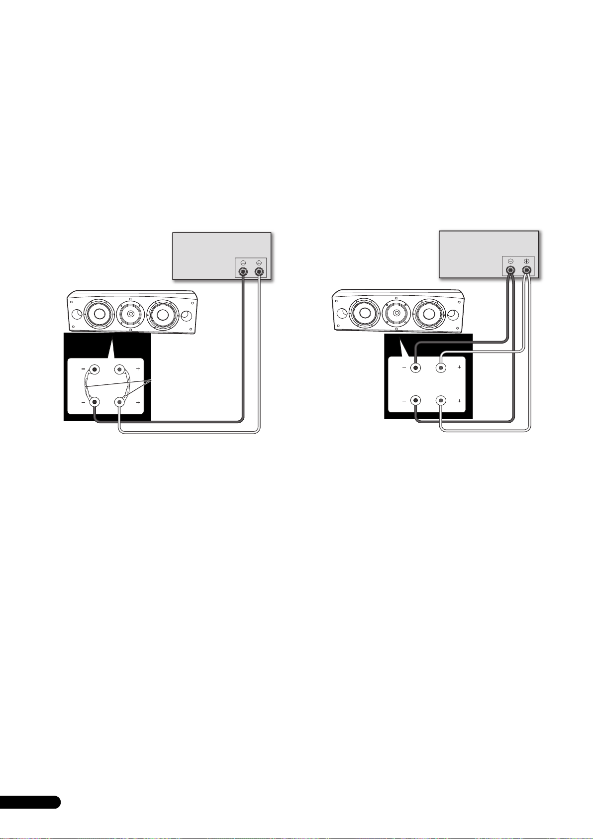
Einzelverdrahtungs-Anschluss
Um einen Einzelverdrahtungs-Anschluss herzustellen, verbinden
Sie jeweils die HF-Klemme (Mitten und Höhen) unter Verwendung
einer der Kurzschlussbrücken im Lieferumfang dieses
Lautsprechers mit der LF-Klemme (Tiefen), und schließen Sie
dann wie in der nachstehenden Abbildung gezeigt den Draht des
positiven (+) Kanals vom Verstärker an einen beliebigen der
beiden roten Polbolzen, und den Draht des negativen (–) Kanals
vom Verstärker an einen beliebigen der beiden schwarzen
Polbolzen an.
Doppelverdrahtungs-Anschluss
Bei der Doppelverdrahtung werden die Klemmen HF (mittlerer
und hoher Frequenzbereich) und LF (tiefer Frequenzbereich) jedes
Lautsprechers separat an den Verstärker angeschlossen. Da der
CST-Treiber und die Bass-Treiber unabhängig voneinander direkt
an den Verstärker angeschlossen werden, bietet Ihnen diese
Anschlussmethode die Möglichkeit, den Kabeltyp für jeden
Treiber zu optimieren. Verbinden Sie ein Kabelpaar mit dem
unteren Polbolzenpaar (Frequenzweiche für Bass-Treiber), und
ein zweites Kabelpaar mit dem oberen Polbolzenpaar
(Frequenzweiche für CST-Treiber). Schließen Sie dann beide
Kabelpaare an die entsprechenden Lautsprecherklemmen des
Verstärkers an. Achten Sie sorgfältig darauf, wie in der
nachstehenden Abbildung gezeigt beide positiven (+) Kabel an
die positiven (+) Klemmen, und beide negativen (–) Kabel an die
negativen (–) Klemmen am Verstärker anzuschließen.
HF
LF
(nur ein Kanal gezeigt)
Verstärker
(Rückseite)
Lautsprecher
HF
KurzschlussbrückenAnschluss
LF
Lautsprecher (Rückwand):
Klemmenfeld
SPEAKERS OUTPUT
Lautsprecher
HF
LF
Lautsprecher (Rückwand):
(nur ein Kanal gezeigt)
Verstärker
(Rückseite)
SPEAKERS OUTPUT
HF
LF
Klemmenfeld
8
Ge
Page 31
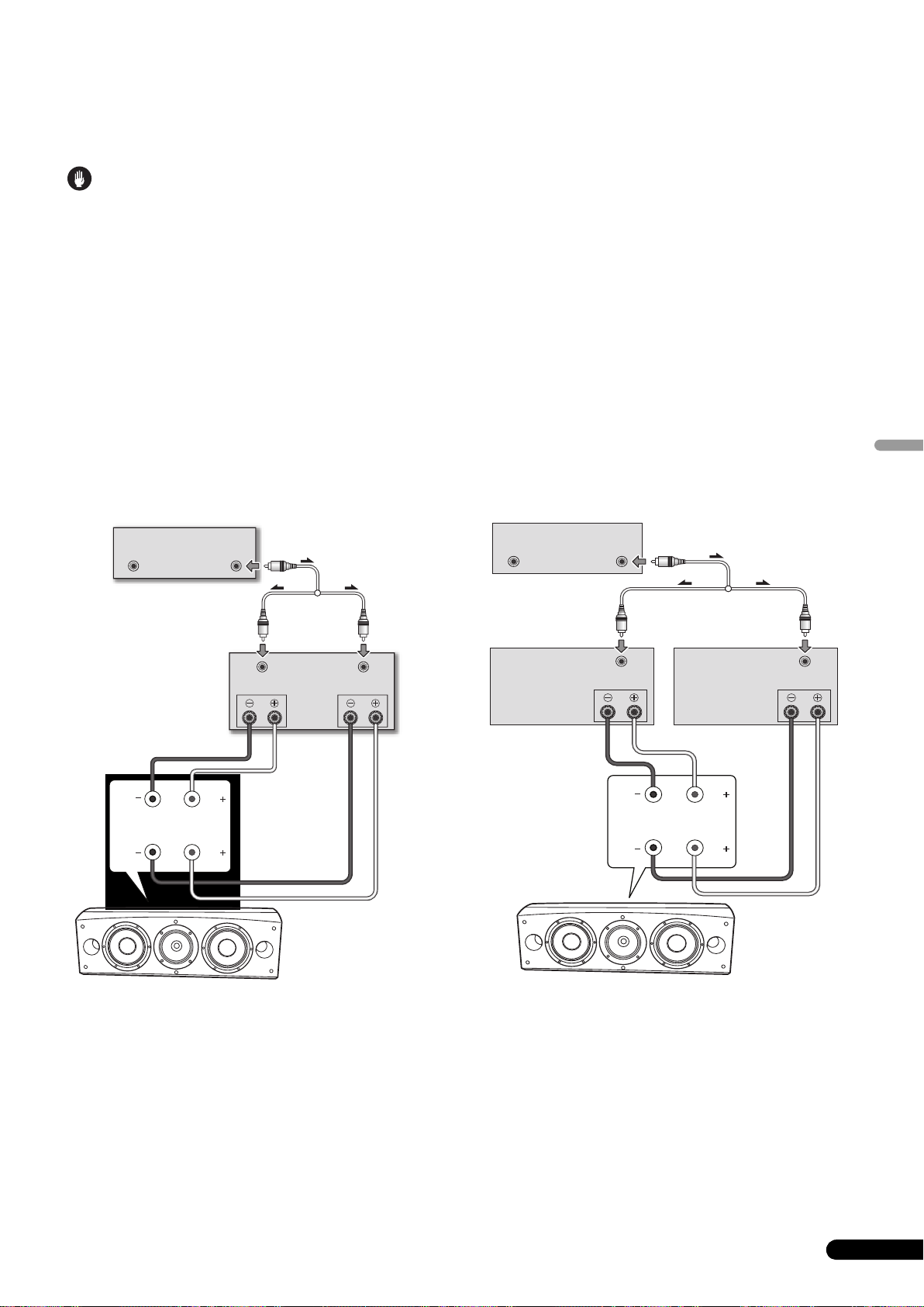
Zweiverstärkeranschluss
Vorsichtshinweise
Die höchste Leistung wird von einem Doppelverdrahtungs-Anschluss erzielt, wenn separate Verstärker für die Tiefen und die Mitten/Höhen
verwendet werden.
Zwei verschiedene Konfigurationen sind möglich, die generell als horizontaler und vertikaler Zweiverstärkeranschluss bezeichnet werden.
Achten Sie unbedingt darauf, die Kurzschlussbrücken zu entfernen, bevor Sie die Lautsprecherkabel in einem Zweiverstärkeranschluss
verbinden.
Anderenfalls besteht die Gefahr, dass die Verstärker beschädigt werden.
Vertikaler Zweiverstärkeranschluss
Bei dieser Konfiguration werden zwei identische Stereoverstärker
für den Anschluss der Lautsprecher verwendet. Wie aus der
nachstehenden Abbildung ersichtlich, treibt dabei jeweils ein
Kanal jedes Verstärkers den hohen Frequenzbereich, während der
andere Kanal den tiefen Frequenzbereich treibt.
Verbinden Sie einen Kanal des Verstärkers über ein Kabelpaar mit
dem unteren Polbolzenpaar (Frequenzweiche für Bass-Treiber).
Verbinden Sie dann den anderen Kanal des Verstärkers über ein
zweites Kabelpaar mit dem oberen Polbolzenpaar
(Frequenzweiche für CST-Treiber).
Achten Sie sorgfältig darauf, beide positiven (+) Kabel an die
positiven (+) Klemmen, und beide negativen (–) Kabel an die
negativen (–) Klemmen am Verstärker anzuschließen.
Vorverstärker (Rückseite)
OUTPUT
(nur ein Kanal gezeigt)
OUTPUT
(handelsüblicher
Y-Adapter)
Leistungsverstärker
INPUT
(Rückseite)
SPEAKERS OUTPUT
Ch.1 Ch.2
INPUT
Horizontaler Zweiverstärkeranschluss
Bei dieser Konfiguration können unterschiedliche
Stereoverstärker zum Treiben des Tieftöners und des Mittel-/
Hochtöners des Lautsprechers verwendet werden (z. B. ein
Röhrenverstärker für die Höhen und ein Festkörperverstärker für
die Tiefen). Wie aus der nachstehenden Abbildung ersichtlich,
treibt jeder Kanal des einen Verstärkers jeweils den Tieftöner eines
Lautsprechers, während jeder Kanal des anderen Verstärkers
jeweils den Mittel-/Hochtöner eines Lautsprechers treibt.
Diese Anschlussmethode setzt voraus, dass beide Verstärker die
gleiche Verstärkung aufweisen; anderenfalls wird keine
einwandfreie Balance zwischen dem Pegel der Tiefen und dem
der Mitten und Höhen erhalten. Bitte konsultieren Sie im
Zweifelsfall Ihren Fachhändler.
Vorverstärker (Rückseite)
OUTPUTOUTPUT
(nur ein Kanal gezeigt)
Leistungsverstärker
(Rückseite) (Höhen)
SPEAKERS OUTPUT
(handelsüblicher Y-Adapter)
INPUT
Leistungsverstärker
(Rückseite) (Tiefen)
(nur ein Kanal gezeigt)(nur ein Kanal gezeigt)
INPUT
SPEAKERS OUTPUT
Deutsch
HF
LF
Lautsprecher
HF
LF
Lautsprecher
(Rückwand):
Klemmenfeld
Lautsprecher
(Rückwand):
Klemmenfeld
HF
LF
Lautsprecher
HF
LF
9
Ge
Page 32

Sonstige Informationen
Verwendung der
Schaumstoffpfropfen
Zum Lieferumfang dieses Lautsprechersystems gehören
Schaumstoffpfropfen, die eine Justierung des Pegels der Bässe
gestatten. Setzen Sie die Schaumstoffpfropfen zum Gebrauch
sacht in die Bassreflexöffnungen auf beiden Seiten des
Lautsprechers ein. Sie können wahlweise nur den
Schaumstoffpfropfen A oder beide Schaumstoffpfropfen, A und B,
verwenden, um den gewünschten Bassklang zu erhalten.
Verwendung von Schaumstoffpfropfen A
Bassreflexöffnungen
Anbringen/Entfernen der
Frontverkleidung
Die Frontverkleidungen dieses Lautsprechersystems können wie
folgt angebracht und abgenommen werden:
1 Zum Anbringen der Frontverkleidung bringen Sie die
Löcher im Lautsprecher mit den Stiften an der
Frontverkleidung zur Deckung, und drücken Sie die
Frontverkleidung dann fest gegen den Lautsprecher.
2 Zum Abnehmen der Frontverkleidung ergreifen Sie ihre
Ober- und Unterkante auf der linken Seite mit beiden
Händen, und ziehen Sie sie sacht nach vorn, um den linken
Teil der Frontverkleidung vom Lautsprechergehäuse zu
trennen.
3 Schieben Sie die Hände bis auf die Mitte der
Frontverkleidung, und ziehen Sie erneut sacht an der Oberund Unterkante, um den mittleren Teil der Frontverkleidung
vom Lautsprechergehäuse zu trennen.
4 Ergreifen Sie abschließend die Ober- und Unterkante auf
der rechten Seite mit beiden Händen, und ziehen Sie sie sacht
nach vorn, um die Frontverkleidung vollständig vom
Lautsprechergehäuse zu trennen.
Verwendung von Schaumstoffpfropfen A und B
Bassreflexöffnungen
Reinigen des Lautsprechergehäuses
Unter normalen Bedingungen lassen sich Staub, Fingerabdrücke
und leichte Verschmutzungen durch Abreiben des
Lautsprechergehäuses mit einem trockenen Tuch entfernen. Falls
hartnäckige Schmutzflecken an den Außenflächen vorhanden
sind, tauchen Sie einen sauberen Lappen in eine Lösung aus 5–6
Teilen eines neutralen Haushaltsreinigers und 1 Teil Wasser,
wringen Sie ihn gründlich aus, und wischen Sie die
Schmutzflecken dann ab. Benutzen Sie dazu keine
Möbelpolituren oder -reinigungsmittel.
Verwenden Sie auf keinen Fall Farbverdünner, Leichtbenzin,
Insektizide oder andere Chemikalien zur Reinigung des Gehäuses
oder in der Nähe dieses Lautsprechers, da derartige Mittel das
Oberflächenfinish anlösen.
10
Ge
Page 33

Technische Daten
Gehäuse. . . . . . . . . . . . . . . . . . . . . . . . . . . . Freistehender Bassreflextyp
(magnetisch abgeschirmt)
Aufbau . . . . . . . . . . . . . . . . . . . . . . . . . . . . . . . . . . . . . . .Dreiweg-System
Tieftöner. . . . . . . . . . . . . . . . . . . . . . . . . . . . . . . . . . . . . 16-cm-Konus x 2
Mittel-Hochtöner . . . . . . . . . . . . . . . . . . . . . 14-cm-Konuslautsprecher/
3-cm-Kalottenlautsprecher
Impedanz . . . . . . . . . . . . . . . . . . . . . . . . . . . . . . . . . . . . . . . . . . . . . . 6 Ω
Frequenzgang . . . . . . . . . . . . . . . . . . . . . . . . . . . . . . . 34 Hz bis 100 kHz
Empfindlichkeit . . . . . . . . . . . . . . . . . . . . . . . . . . . . . . . . 88,5 dB (2,83 V)
Maximale Belastbarkeit . . . . . . . . . . . . . . . . . . . . . . . . . . . . . . . . . 160 W
Außenabmessungen . . . . . . . 723 (B) mm x 263 (H) mm x 387 (T) mm
Masse. . . . . . . . . . . . . . . . . . . . . . . . . . . . . . . . . . . . . . . . . . . . . . . . . 28 kg
Mitgeliefertes Zubehör
Stabilisatoren . . . . . . . . . . . . . . . . . . . . . . . . . . . . . . . . . . . . . . . . . . . . . 3
Korkuntersetzer. . . . . . . . . . . . . . . . . . . . . . . . . . . . . . . . . . . . . . . . . . . . 3
Große rutschfeste Kissen. . . . . . . . . . . . . . . . . . . . . . . . . . . . . . . . . . . . 2
Kleine rutschfestes Kissen . . . . . . . . . . . . . . . . . . . . . . . . . . . . . . . . . . 4
Schaumstoffpfropfen (A, B). . . . . . . . . . . . . . . . . . . . . . . . . . . . . . . . . . 2
Lautsprecher-Trägerplatte . . . . . . . . . . . . . . . . . . . . . . . . . . . . . . . . . . . 1
Unterlegscheibe . . . . . . . . . . . . . . . . . . . . . . . . . . . . . . . . . . . . . . . . . . . 2
Federscheibe. . . . . . . . . . . . . . . . . . . . . . . . . . . . . . . . . . . . . . . . . . . . . . 1
Schraube (M5 x L40). . . . . . . . . . . . . . . . . . . . . . . . . . . . . . . . . . . . . . . . 1
Schrauben (M6 x L35). . . . . . . . . . . . . . . . . . . . . . . . . . . . . . . . . . . . . . . 6
Frontverkleidung . . . . . . . . . . . . . . . . . . . . . . . . . . . . . . . . . . . . . . . . . . 1
Bedienungsanleitung
Hinweis
Änderungen der technischen Daten und äußeren Aufmachung
bleiben im Sinne der ständigen Produktverbesserung jederzeit
vorbehalten.
Magnetische Abschirmung
Dieses Lautsprechersystem ist mit einer magnetischen
Abschirmung ausgestattet. Je nach Aufstellungsort kann es
jedoch vorkommen, dass Farbstörungen auftreten, wenn dieser
Lautsprecher in unmittelbarer Nähe eines Fernsehgerätes
platziert wird.
In einem solchen Fall schalten Sie das Fernsehgerät aus, warten
Sie etwa 15 bis 30 Minuten lang, und schalten Sie es dann erneut
ein. Falls sich die Störung auf diese Weise nicht beseitigen lässt,
stellen Sie den Lautsprecher in einem größeren Abstand vom
Fernsehgerät auf.
ist eine Marke, mit der Geräte gekennzeichnet sind, die
mit Pioneers Phase Control-Technologie ausgestattet sind. Diese
Technologie gewährleistet eine hochwertige Klangreproduktion
des betreffenden Gerätes durch eine Verbesserung der
Gesamtphasenanpassung.
Deutsch
Veröffentlicht von Pioneer Corporation.
Urheberrechtlich geschützt © 2008 Pioneer Corporation.
Alle Rechte vorbehalten.
11
Ge
Page 34

Vi ringraziamo per avere acquistato questo prodotto Pioneer.
Prima di usare il prodotto, leggere questo manuale d’istruzioni in modo da saperlo utilizzare correttamente.
Finito di leggerle, conservarle in un luogo sicuro per poterle riutilizzare in futuro.
Indice
Prima di cominciare
Contenuto della confezione
La serie EX
Tecnologia dietro gli S-8EX . . . . . . . . . . . . . . . . . . . . . . . . . . . . . . . 3
CST. . . . . . . . . . . . . . . . . . . . . . . . . . . . . . . . . . . . . . . . . . . . . . . . 3
Diaframma in ceramica di grafite . . . . . . . . . . . . . . . . . . . . . . . . . 3
Diaframma in lega di magnesio . . . . . . . . . . . . . . . . . . . . . . . . . . 4
Driver dei bassi. . . . . . . . . . . . . . . . . . . . . . . . . . . . . . . . . . . . . . . 4
Struttura della cassa dei bassi . . . . . . . . . . . . . . . . . . . . . . . . . . . 4
Reti di crossover. . . . . . . . . . . . . . . . . . . . . . . . . . . . . . . . . . . . . . 4
Collaborazione con gli Air Studios . . . . . . . . . . . . . . . . . . . . . . . . 4
Installazione e collocazione
Norme di installazione . . . . . . . . . . . . . . . . . . . . . . . . . . . . . . . . . . 5
Se si installa il diffusore sul pavimento. . . . . . . . . . . . . . . . . . . . . 5
Uso della base del diffusore in dotazione . . . . . . . . . . . . . . . . . . . 5
Uso della base per diffusore Pioneer CP-7EX . . . . . . . . . . . . . . . . 6
Scelta della posizione di installazione dei diffusori . . . . . . . . . . . . 6
Collegamenti
Collegamento con un amplificatore . . . . . . . . . . . . . . . . . . . . . . . . 7
Collegamento dei cavi . . . . . . . . . . . . . . . . . . . . . . . . . . . . . . . . . . . 7
Collegamenti a filo singolo . . . . . . . . . . . . . . . . . . . . . . . . . . . . . . 8
Collegamenti a doppio filo . . . . . . . . . . . . . . . . . . . . . . . . . . . . . . 8
Collegamenti a doppio amplificatore . . . . . . . . . . . . . . . . . . . . . . 9
Altre informazioni
Uso dei tappi in schiuma . . . . . . . . . . . . . . . . . . . . . . . . . . . . . . . 10
Uso del solo tappo in schiuma A . . . . . . . . . . . . . . . . . . . . . . . . 10
Uso dei tappi in schiuma A e B. . . . . . . . . . . . . . . . . . . . . . . . . . 10
Applicazione e rimozione della griglia di copertura . . . . . . . . . . . . 10
Pulizia del cabinet dei diffusori . . . . . . . . . . . . . . . . . . . . . . . . . . . 10
Dati tecnici . . . . . . . . . . . . . . . . . . . . . . . . . . . . . . . . . . . . . . . . . . 11
Prima di cominciare
• L’impedenza nominale di questo diffusore è 6 Ω. Collegare il
diffusore ad un amplificatore dotato di un’impedenza di carico
che vada da 6 Ω a 16 Ω (un modello che porti sui terminali di
collegamento dei diffusori l’indicazione “6 Ω – 16 Ω”).
Per evitare danni al diffusore dovuti al sovraccarico di segnale
in ingresso, osservare le seguenti norme:
• Non alimentare il diffusore con potenza oltre il massimo
concesso.
• Se si usa un equalizzatore grafico per enfatizzare forti suoni di
alta frequenza, non usare volumi eccessivi dell’amplificatore.
• Non tentare di forzare un amplificatore di bassa potenza a
produrre alti volumi. La distorsione armonica
dell’amplificatore aumenterebbe e potreste danneggiare il
diffusore.
Attenzione: installazione
• Nell’installare quest’unità, controllare che sia ben ferma ed
evitare le aree dove potrebbe cadere e causare ferimenti nel
caso di disastri naturali, ad esempio un terremoto.
• Non installare questi diffusori su di un muro o parete. Essi
possono cadere e causare ferite.
• Non installare i diffusori in alto su di un soffitto o su di una
parete. Se male installati, la griglia potrebbe cadere e causare
danni o ferite.
• Prima di fare collegamenti, spegnere i propri componenti AV,
scollegarli e consultarne i manuali. Controllare di avere usato
i cavi di collegamento corretti.
Attenzione: in uso
• Non installare il diffusore su superfici poco stabili. Esso in
caso di caduta può causare incidenti e danneggiarsi.
• Non fare emettere al diffusore suono distorto per lunghi
periodi. Questo può provocare incendi.
• Non sedere o appoggiarsi al diffusore, e non lasciare che i
bambini ci giochino.
• Non posare oggetti grandi o pesanti sul diffusore.
• Non posare oggetti che producono campi magnetici, ad
esempio cacciaviti o pezzi di metallo, vicino al tweeter o al
midrange. Dato che i diffusori incorporano forti magneti,
questi oggetti possono venirne attratti, causando ferite o
danneggiando il diaframma.
Se si vuole eliminare questo prodotto, non gettarlo insieme ai rifiuti domestici. Esiste un sistema di raccolta differenziata in conformità
alle leggi che richiedono appositi trattamenti, recupero e riciclo.
I privati cittadini dei paesi membri dell’UE, di Svizzera e Norvegia, possono restituire senza alcun costo i loro prodotti elettronici usati ad appositi
servizi di raccolta o a un rivenditore (se si desidera acquistarne uno simile).
Per i paesi non citati qui sopra, si prega di prendere contatto con le autorità locali per il corretto metodo di smaltimento.
In questo modo, si è sicuri che il proprio prodotto eliminato subirà il trattamento, il recupero e il riciclo necessari per prevenire gli effetti
potenzialmente negativi sull’ambiente e sulla vita dell’uomo.
2
It
K058_A_It
Page 35

Contenuto della
A
B
confezione
Punte x 3
Cuscinetti in sughero x 3
Cuscinetti antiscivolamento grandi x 2
La serie EX
La serie EX, che include il grande know-how della serie di
diffusori Pioneer TAD, è stata sviluppata per creare i diffusori
migliori possibili in questa gamma di prezzo.
Il design e la produzione della serie EX sono il risultato di uno
sforzo di livello internazionale che rappresenta quanto c’è di
meglio nella tecnologia per diffusori di Pioneer.
Tecnologia dietro gli S-8EX
CST
Al cuore del sistema c’è un Coherent Source Trasducer (CST) o
trasduttore a sorgente coerente, derivante dalla tecnologia usata
nei diffusori TAD. Il diaframma del tweeter è installato
concentricamente entro l’apice del cono del midrange e genera
una sorgente puntiforme di suono per frequenze fra i
400 Hz e gli 100 kHz. Il CST assicura un perfetto bilanciamento
spettrale fra I suoni diretti e quelli riflessi che arrivano
all’ascoltatore, rendendo il suono più costante in tutta la stanza e
migliorando l’immagine acustica.
Cuscinetti antiscivolamento piccoli x 4
Tappi in schiuma (A,B) x 2
Base del diffusore x 1
Rondelle x 2
Rondella elastica x 1
Vite (M5 x L40) x 1
Viti (M6 x L35) x 6
Griglia x 1
Istruzioni per l’uso
Diaframma in ceramica di grafite
Il tweeter del CST possiede diaframmi in ceramica di grafite dotati
di caratteristiche di grandissima resistenza e smorzamento,
praticamente senza rivali fra i materiali disponibili ed in uso per
diffusori di alto livello. La leggerezza e l’eccezionale resistenza
della ceramica di grafite si combinano a creare diffusori la
risonanza dei cui diaframmi può venire spinta ben oltre la gamma
dell’udibile.
Velocità (m/s)
18 000
16 000
14 000
12 000
10 000
8 000
6 000
4 000
2 000
0
0,005 0,015
Perdita interna
C
eramica d
A
lluminio
B
erilli
L
ega d
C
arbonio ceramic
C
art
T
itani
0,025
i grafite
o
i boro
a
o
o
Italiano
3
It
Page 36

Diaframma in lega di magnesio
Il midrange del CST possiede un diaframma in lega di magnesio
le cui caratteristiche di leggerezza e alte perdite interne
permettono un’alta transitorietà ed una colorazione minima dei
toni medi.
Driver dei bassi
Il driver dei bassi visto di seguito sta alla base dei diffusori S-8EX.
La forza di questo driver è il risultato del materiale composto di
aramide/carbonio, creato originariamente durante lo sviluppo
degli S-1EX, usato nel suo diaframma. La tecnologia di circuito
magnetico LDMC, esclusiva di Pioneer, è stata incorporata per
poter preservare la linearità da livelli bassi a livelli alti,
minimizzando la distorsione.
Struttura della cassa dei bassi
La forma unica degli S-8EX si basa su una necessità logica. Per
poter sincronizzare i tempi di arrivo del suono dal CST e dai due
driver dei bassi, ciascun driver è collocato su di uno schermo
acustico che contribuisce a creare una curva delicatissima
conosciuta come “curva di precisione” (vedi l’illustrazione che
segue). Costituito da una MDF (Medium Density Fiberboard, o
tavola in fibra di vetro di media densità) spessa fino a 65 mm,
questo schermo acustico è sufficientemente forte da contenere la
forza degli elementi conduttori. Inoltre, l’apertura dei bassi è stata
scolpita in un blocco estremamente spesso di MDF, producendo
una riduzione del rumore del vento e quindi bassi chiari e
profondi.
Reti di crossover
Le reti di crossover usano solo componenti di prima scelta. Le
bobine con anima in aria, le resistenza non induttive ed i
condensatori a pellicola sul percorso del segnale sono stati scelti
con cura ed ottimizzati per il driver CST in modo da produrre
segnale il più trasparente possibile. I driver dei bassi usano
induttori al silicone con anima a piastrine di acciaio che
minimizzano la distorsione e le perdite durante il trasferimento di
energia. Tutti i componenti sono collegati direttamente ai loro cavi
e non ad una scheda a circuiti stampati, permettendo perdite
minime e prestazioni massime.
Collaborazione con gli Air Studios
Dalla loro fondazione da parte di George Martin nel 1969 a Londra,
gli inglesi Air Studios si sono guadagnati il rispetto unanime di
artisti che lo riconoscono essere il miglior studio di registrazione
del mondo. Gli Air Studios hanno dato agli S-8EX il loro sigillo di
approvazione ad indicare che sono in grado di produrre la grande
qualità acustica richiesta dai creatori delle sonorità più pure del
mondo.
Curva di precisione
4
It
Page 37

Installazione e collocazione
Importante
Uso della base del diffusore in dotazione
Norme di installazione
Scegliere un tipo di installazione fra i seguenti.
Se si installa il diffusore sul pavimento
Per installare il diffusore direttamente sul pavimento, usare le
punte in dotazione.
Installazione
1 Girare le punte avvitandole negli inserti filettati (M6)
facenti parte del fondo del diffusore e stringerle bene.
Punta
Se si usa la base del diffusore in dotazione, le punte in dotazione
non sono necessarie.
Installazione
1 Fissare i cuscinetti antislittamento (piccoli) nei quattro
punti sul fondo della base.
2 Fissare i cuscinetti antislittamento (grandi) nei due punti
della superficie superiore della base del diffusore.
Cuscinetti antiscivolamento piccoli
Fondo del
diffusore
2 Mettere i cuscinetti in sughero nelle posizioni dove le tre
punte toccano quando il diffusore viene messo in posizione.
3 Posare il diffusore sui cuscinetti in sughero.
Se non si usano i cuscinetti in sughero nell'installare i
diffusori, le punte possono causare danni al
pavimento. Raccomandiamo caldamente l'uso dei
cuscinetti in sughero a chi intende usare le punte.
• Quest’unità pesa ben 28 kg ed è quindi molto pericoloso
provare a regolare il dado delle sue punte inclinando il
diffusore. Posare quest’unità sempre su qualcosa di morbido,
ad esempio una coperta, in modo che non danneggi il
pavimento ed installarla sempre insieme ad un assistente.
Cuscinetti antiscivolamento g
3 Posare il diffusore sulla base.
Usando la base del diffusore in dotazione è possibile regolare
in modo fine l'angolazione del diffusore.
Base del
diffusore
randi
Italiano
Importante
• Se si usa la base del diffusore in dotazione, non fissare il
diffusore in posizione con viti. Il diffusore potrebbe cadere e
causare incidenti.
5
It
Page 38

Uso della base per diffusore Pioneer CP-7EX
Per usare la base CP-7EX, la base del diffusore in dotazione deve
venire applicata agli steli della CP-7EX. Installare le basi nel modo
visto di seguito.
Installazione
1 Rimuovere il materiale di imballaggio dai fori per viti
nella base del diffusore.
Scelta della posizione di installazione dei diffusori
La posizione all’interno della stanza di ascolto ha un grande
impatto sulle prestazioni generali del diffusore S-8EX in termini di
riproduzione dei bassi, accuratezza tonale ed immagine acustica.
Ogni stanza ha le sue peculiarità e quanto segue è semplicemente
una guida. La sperimentazione è il metodo migliore per
raggiungere buoni risultati.
Usare il grafico che segue come guida per determinare la
posizione ottimale per questi diffusori.
Da 30 cm a 60 cm
2 Applicare la base del diffusore agli steli della CP-7EX.
Usare solo le viti (M6 x L35) in dotazione.
Viti (M6 x L35)
Base del
diffusore
Steli della base
Basamento della base
CP-7EX
3 Fissare i cuscinetti antiscivolamento (grandi).
4 Usare le viti in dotazione (M5 x L40), la rondella elastica e
la rondella per fissare il diffusore alla sua base.
Per evitare che il diffusore cada, per fissare il diffusore alla sua
base usare solo le viti in dotazione. Per dettagli, consultare le
istruzioni in dotazione alla base per diffusori CP-7EX.
.
Diffusore
anteriore
Diffusore centrale
Posizione di ascolto
Diffusore
anteriore
Importante
• Non mettere il diffusore dove sarà esposto a luce solare diretta
ed evitare di installarlo vicino a caloriferi e climatizzatori. Esso
potrebbe altrimenti deformarsi e scolorirsi, danneggiandosi
anche gravemente.
• Pioneer non si assume alcuna responsabilità per danni
risultanti da una scorretta messa in posa, un insufficiente
rinforzo, un uso scorretto del prodotto, catastrofi naturali, ecc.
Cuscinetti antiscivolamento grandi
Rondelle
Rondella elastica
Vite (M5 x L40)
6
It
Page 39

Collegamenti
Collegamento con un amplificatore
Questo diffusore non include cavi per diffusori usati per il
collegamento con un amplificatore. Nello scegliere i cavi dei
diffusori, per poter ottenere il meglio che possono dare prendere
sempre il considerazione i fattori seguenti:
• Usare cavi per diffusori di grosso diametro, se possibile, e
ridurne al minimo la lunghezza.
• I cavi hanno caratteristiche differenti. Non dimenticare mai
questo fatto nello sceglierli.
• Scegliere cavi di resistenza il più bassa possibile e controllare
che i cavi dei terminali dei diffusori e dell’amplificatore siano
ben fissati.
AVVERTENZA
I terminali degli altoparlanti sono sotto tensione, alla
stessa PERICOLOSA tensione della corrente di rete.
Per prevenire rischi di folgorazioni nel corso delle
operazioni di collegamento o di distacco dei cavi degli
altoparlanti, staccare il cavo di alimentazione principale
prima di toccare qualsiasi parte non isolata.
D3-4-2-2-3_A_It
Collegamento dei cavi
1 Spegnere l’amplificatore.
2 Collegare i cavi dei diffusori ai terminali di ingresso
(inferiori) sul retro del diffusore. Il terminale dei diffusori
positivo (+) è rosso, quello negativo (–) nero.
3 Collegare le estremità dei cavi ai terminali di uscita dei
diffusori dell’amplificatore. Per maggiori dettagli, consultare
il manuale del proprio amplificatore.
Connettori con barra
di messa in corto
Terminale rosso (+)
Terminale nero
(–)
• Prendere le manopole dei terminali di ingresso inferiori,
girarle verso sinistra (in senso antiorario) ed inserire i cavi dei
diffusori nei fori dei terminali, quindi stringere le manopole
per fermare sia la barra breve che i cavi.
• Potete anche collegare i terminali dei diffusori con uno
spinotto a banana. Se si usa uno spinotto a banana, togliere
sempre il cappuccio in cima al terminale di ingresso.
• Dopo aver rimesso a posto i tappi, tirare leggermente i cavi per
controllare che siano ben collegati ai rispettivi terminali.
Collegamenti scadenti possono causare rumore ed
interruzioni del suono.
• Se i conduttori dei cavi fuoriescono dai terminali ed entrano in
contatto l’uno con l’altro, il carico posto sull’amplificatore è
eccessivo. Questo può impedirne il funzionamento o
addirittura danneggiarlo.
Italiano
7
It
Page 40

Collegamenti a filo singolo
SPEAKERS OUTPUT
Collegamento di
messa in corto
Diffusore (retro): Pannello d’ingresso
Amplificatore (retro)
(Viene mostrato un solo canale)
Diffusore
HF
HF
LF
LF
Nel caso di collegamenti a filo singolo, collegare le sezioni delle
frequenze medio-alte e basse della rete di crossover con il
collegamento di messa in corto accluso all’unità, poi collegare il
filo (+) del proprio amplificatore al terminale rosso ed il filo (–) del
proprio amplificatore al terminale nero nel modo indicato qui di
seguito.
Collegamenti a doppio filo
Nel caso si usino collegamenti a doppio filo, si collegano
indipendentemente i diffusori alle prese delle alte e basse
frequenze. Questo fa sì che il driver CST ed i driver dei bassi
vengano collegati direttamente ed indipendentemente
all’amplificatore, offrendo la possibilità di ottimizzare il tipo di cavo
a seconda del suo scopo. Collegare una serie di fili alla serie
inferiore di terminali (rete specifica per i bassi). Collegare poi una
seconda serie di fili alla serie superiore di terminali (rete specifica
CST). Collegare poi ambedue le coppie di fili ai terminali rispettivi
dell’amplificatore. Collegare ambedue i fili (+) ai terminali (+)
dell’amplificatore ed ambedue i fili (–) ai terminali (–)
dell’amplificatore nel modo visualizzato di seguito.
(Viene mostrato un solo canale)
Amplificatore (retro)
SPEAKERS OUTPUT
Diffusore
HF
LF
HF
LF
Diffusore (retro): Pannello d’ingresso
8
It
Page 41
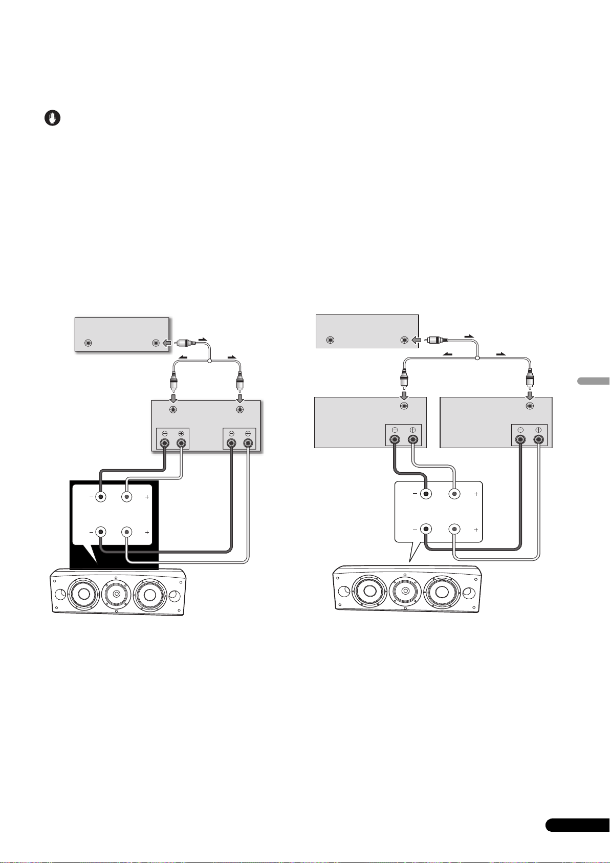
Collegamenti a doppio amplificatore
Attenzione
La doppia amplificazione permette di ottenere le migliori prestazioni grazie all’uso di amplificatori dedicati specificamente ai medi ed agli
acuti.
Ci sono due possibili configurazioni, indicate comunemente rispettivamente come doppia amplificazione orizzontale e verticale.
Prima di collegare i cavi dei diffusori in una configurazione a doppia amplificazione, togliere sempre i collegamenti di messa in corto.
Non facendolo si danneggiano gli amplificatori.
Doppia amplificazione verticale
In questa configurazione, due identici amplificatori stereo
vengono usati per ciascun diffusore. Un canale di ciascun
amplificatore pilota la sezione delle basse frequenze e l’altro la
sezione delle alte frequenze nel modo indicato qui di seguito.
Collegare una serie di fili dall’uscita di un canale alla serie
inferiore di terminali (rete specifica per i bassi).
Collegare poi una seconda serie di fili dall’altro canale
dell’amplificatore alla serie superiore di terminali (rete specifica
CST).
Collegare ambedue i fili (+) ai terminali (+) dell’amplificatore ed
ambedue i fili (–) ai terminali (–) dell’amplificatore.
Preamplificatore (posteriore)
OUTPUT
(Viene mostrato
un solo canale)
OUTPUT
(Adattatore Y da
acquistare
separatamente)
Amplificatore di
potenza
INPUT
(posteriore)
SPEAKERS OUTPUT
Ch.1 Ch.2
INPUT
Doppia amplificazione orizzontale
In questa configurazione si possono usare differenti amplificatori
stereo per le sezioni dei bassi e delle frequenze medio-alte dei
diffusori, ad esempio amplificatori a valvole per le alte frequenze
ed a stato solido per le basse frequenze. Ciascun canale degli
amplificatori pilota la sezione delle basse frequenze di ciascun
diffusore e ciascun canale dell’altro amplificatore pilota la sezione
delle frequenze medio-alte nel modo indicato qui di seguito.
Questo metodo richiede un uguale guadagno di ambedue gli
amplificatori per evitare una perdita di bilanciamento nella
riproduzione delle basse frequenze e delle medie frequenze dai
diffusori. In caso di dubbi, consultare il proprio negoziante di
fiducia.
Preamplificatore (posteriore)
OUTPUTOUTPUT
(Viene mostrato un
solo canale)
Amplificatore di potenza
(pannello posteriore)
(alte frequenze)
(Viene mostrato un
solo canale)
SPEAKERS OUTPUT
(Adattatore Y da acquistare
separatamente)
Amplificatore di potenza
INPUT
(pannello posteriore)
(basse frequenze)
(Viene mostrato un
solo canale)
INPUT
SPEAKERS OUTPUT
Italiano
HF
LF
Diffusore
HF
Diffusore (retro):
Pannello d’ingresso
LF
Diffusore (retro):
Pannello d’ingresso
HF
LF
Diffusore
HF
LF
9
It
Page 42

Altre informazioni
Uso dei tappi in schiuma
Questa unità viene fornita con dei tappi in gomma utili per
regolare il volume dei bassi. Per farne uso, metterlo piano nelle
porte bass-reflex su ambedue i lati del diffusore. Inserire o il solo
tappo in schiuma A o sia quello A sia quello B fino a raggiungere
il suono desiderato.
Uso del solo tappo in schiuma A
Porte bass-reflex
Applicazione e rimozione della
griglia di copertura
Questo diffusore possiede una griglia di copertura installabile e
rimovibile nel modo seguente:
1 Per applicare la copertura della griglia, allineare i fori del
diffusore con le sporgenze della griglia e premere
fermamente.
2 Per togliere la griglia, prenderne i bordi superiore ed
inferiore sulla sinistra con le mani e tirare lentamente verso
di sé per separarla dal diffusore.
3 Portare quindi le mani al centro della griglia e tirare piano
i bordi superiore ed inferiore verso di sé per separarne il
centro.
4 Infine, prendere i bordi superiore ed inferiore della griglia
sulla destra e tirare verso di sé per separare la porzione
rimanente della griglia dal diffusore.
Uso dei tappi in schiuma A e B
Porte bass-reflex
Pulizia del cabinet dei diffusori
Normalmente per mantenere pulito il diffusore dovrebbe bastare
un panno morbido ed asciutto. Se necessario, passarlo con un
panno inumidito con un detergente neutro diluito cinque o sei
volte con acqua, quindi strizzarlo bene. Non usare cere o pulenti
per mobilia.
Non usare mai diluenti, benzina, spray insetticidi o altre sostanze
chimiche su o vicino a quest’unità, dato che essi ne corrodono la
superficie.
10
It
Page 43

Dati tecnici
Cassa . . . . . . . . . . . . . . . . . . . . . . . . . . . . Tipo bass-reflex da pavimento
(schermata magneticamente)
Configurazione . . . . . . . . . . . . . . . . . . . . . . . . . . . . . . . . . . . . . . .a tre vie
Woofer . . . . . . . . . . . . . . . . . . . . . . . . . . . . . . . . . . . . .Cono da 16 cm x 2
Mid tweeter . . . . . . . . . . . . . . . . . . . . . . cono da 14 cm/cupola da 3 cm
Impedenza nominale . . . . . . . . . . . . . . . . . . . . . . . . . . . . . . . . . . . . . 6 Ω
Risposta in frequenza. . . . . . . . . . . . . . . . . . . . . . . . Da 34 Hz a 100 kHz
Sensibilità . . . . . . . . . . . . . . . . . . . . . . . . . . . . . . . . . . . . 88,5 dB (2,83 V)
Potenza in ingresso massima . . . . . . . . . . . . . . . . . . . . . . . . . . . . 160 W
Dimensioni esterne . . . . . . . . 723 (L) mm x 263 (A) mm x 387 (P) mm
Peso . . . . . . . . . . . . . . . . . . . . . . . . . . . . . . . . . . . . . . . . . . . . . . . . . . 28 kg
Nota
I dati tecnici ed il design sono soggetti a modifiche senza
preavviso a causa di migliorie.
Schermatura magnetica
Questo diffusore è schermato magneticamente. Tuttavia, se il
diffusore è installato estremamente vicino ad un televisore, può
causare aberrazioni cromatriche.
Se questo accade, spegnere il televisore e riaccenderlo dopo
15 minuti a 30 minuti. Se il problema persiste, allontanare i
diffusori dal televisore.
Accessori in dotazione
Punte . . . . . . . . . . . . . . . . . . . . . . . . . . . . . . . . . . . . . . . . . . . . . . . . . . . . 3
Cuscinetti in sughero . . . . . . . . . . . . . . . . . . . . . . . . . . . . . . . . . . . . . . . 3
Cuscinetti antiscivolamento grandi . . . . . . . . . . . . . . . . . . . . . . . . . . . 2
Cuscinetti antiscivolamento piccoli . . . . . . . . . . . . . . . . . . . . . . . . . . . 4
Tappi in schiuma (A,B). . . . . . . . . . . . . . . . . . . . . . . . . . . . . . . . . . . . . . 2
Base del diffusorie . . . . . . . . . . . . . . . . . . . . . . . . . . . . . . . . . . . . . . . . . 1
Rondelle. . . . . . . . . . . . . . . . . . . . . . . . . . . . . . . . . . . . . . . . . . . . . . . . . . 2
Rondella elastica . . . . . . . . . . . . . . . . . . . . . . . . . . . . . . . . . . . . . . . . . . 1
Vite (M5 x L40). . . . . . . . . . . . . . . . . . . . . . . . . . . . . . . . . . . . . . . . . . . . . 1
Viti (M6 x L35) . . . . . . . . . . . . . . . . . . . . . . . . . . . . . . . . . . . . . . . . . . . . . 6
Griglia . . . . . . . . . . . . . . . . . . . . . . . . . . . . . . . . . . . . . . . . . . . . . . . . . . . 1
Istruzioni per l’uso
è un marchio di fabbrica messo sul prodotto che utilizza
la tecnologia Phase Control di Pioneer. Questa tecnologia
permette una riproduzione audio di alta qualità attraverso i vari
componenti regolandone la fase.
Pubblicato da Pioneer Corporation.
Copyright © 2008 Pioneer Corporation.
Tutti i diritti riservati.
Italiano
11
It
Page 44

Hartelijk dank voor de aanschaf van dit Pioneer product.
Lees de handleiding aandachtig door zodat u volledig op de hoogte bent van de bediening en werking.
Bewaar de handleiding op een veilige plaats voor eventuele naslag in de toekomst.
Inhoudsopgave
Voordat u begint
Inhoud van de doos
Informatie over de EX-serie
De technologie achter de S-8EX . . . . . . . . . . . . . . . . . . . . . . . . . . . 3
CST. . . . . . . . . . . . . . . . . . . . . . . . . . . . . . . . . . . . . . . . . . . . . . . . 3
Membraan van keramisch grafiet . . . . . . . . . . . . . . . . . . . . . . . . . 3
Membraan van magnesiumlegering. . . . . . . . . . . . . . . . . . . . . . . 4
Basdrivers . . . . . . . . . . . . . . . . . . . . . . . . . . . . . . . . . . . . . . . . . . 4
Constructie van de basbehuizing . . . . . . . . . . . . . . . . . . . . . . . . . 4
Crossover-netwerken . . . . . . . . . . . . . . . . . . . . . . . . . . . . . . . . . . 4
Samenwerking met Air Studios . . . . . . . . . . . . . . . . . . . . . . . . . . 4
Installatie en opstelling
Installatie . . . . . . . . . . . . . . . . . . . . . . . . . . . . . . . . . . . . . . . . . . . . 5
Wanneer de luidspreker direct op de vloer wordt geplaatst. . . . . . 5
Gebruik van de bijgeleverde luidsprekervoet . . . . . . . . . . . . . . . . . 5
Gebruik van de Pioneer luidsprekerstandaard CP-7EX . . . . . . . . . 6
Kiezen van een plaats voor de luidsprekers. . . . . . . . . . . . . . . . . . 6
Aansluitingen
Aansluiten op een versterker. . . . . . . . . . . . . . . . . . . . . . . . . . . . . . 7
Aansluiten van de kabels . . . . . . . . . . . . . . . . . . . . . . . . . . . . . . . . 7
Enkeldraads verbindingen . . . . . . . . . . . . . . . . . . . . . . . . . . . . . . 8
Dubbeldraads verbindingen . . . . . . . . . . . . . . . . . . . . . . . . . . . . . 8
Verbindingen voor biversterking . . . . . . . . . . . . . . . . . . . . . . . . . . 9
Aanvullende informatie
Gebruik van de schuimpluggen. . . . . . . . . . . . . . . . . . . . . . . . . . . 10
Gebruik van enkel schuimplug A . . . . . . . . . . . . . . . . . . . . . . . . 10
Gebruik van schuimplug A en B . . . . . . . . . . . . . . . . . . . . . . . . . 10
Bevestigen/verwijderen van het luidsprekerfront. . . . . . . . . . . . . . 10
Schoonmaken van de luidsprekerbehuizing . . . . . . . . . . . . . . . . . 10
Technische gegevens . . . . . . . . . . . . . . . . . . . . . . . . . . . . . . . . . . 11
Voordat u begint
• De nominale impedantie van deze luidsprekers is 6 Ω. Sluit de
luidsprekers op een versterker aan met een
belastingsimpedantie tussen 6 Ω en 16 Ω (een model met het
opschrift “6 Ω – 16 Ω” op de
luidsprekeruitgangsaansluitingen).
Om beschadiging van de luidsprekers als gevolg van
overbelasting te voorkomen, dient u de volgende punten in
acht te nemen:
• De stroomtoevoer naar de luidsprekers mag het maximaal
toelaatbare ingangsvermogen niet overschrijden.
• Bij gebruik van een grafische equalizer voor het versterken van
de hoge tonen, mag het volume van de versterker niet te hoog
worden ingesteld.
• Probeer niet om een versterker met laag vermogen geluid met
overmatig hoog volume te laten weergeven (de harmonische
vervorming van de versterker zal toenemen, wat kan resulteren
in beschadiging van de luidspreker).
Let op: opstelling
• Zet de luidspreker op een stabiele ondergrond en let erop dat
de luidspreker niet kan vallen en letsel veroorzaken bij een
onvoorziene situatie of natuurramp (zoals een aardbeving).
• Bevestig de luidsprekers niet aan een muur of het plafond. De
luidsprekers kunnen vallen en letsel veroorzaken.
• Monteer de luidsprekers niet boven u aan het plafond of aan
een muur. Als de luidspreker verkeerd is bevestigd, kan het
luidsprekerfront vallen met beschadiging of letsel tot gevolg.
• Schakel de AV-apparatuur uit, haal de stekker uit het
stopcontact en raadpleeg de handleidingen voordat u begint
met het aansluiten van apparatuur. Zorg dat u de juiste
aansluitkabels gebruikt.
Let op: gebruik
• Zet de luidspreker niet op een onstabiele ondergrond. De
luidspreker kan gevaar opleveren wanneer deze omvalt of de
apparatuur kan beschadigd worden.
• Laat de luidspreker niet gedurende langere tijd vervormd
geluid weergeven. Dit kan resulteren in brand.
• Ga niet op de luidspreker zitten of staan en laat ook niet
kinderen op de luidspreker spelen.
• Zet geen grote of zware voorwerpen op de luidspreker.
• Leg geen voorwerpen die door magneten worden
aangetrokken, zoals schroevendraaiers of ijzeren voorwerpen,
in de buurt van de tweeter of midrange. Aangezien er sterke
magneten in de luidsprekers zijn, kunnen de voorwerpen
worden aangetrokken met persoonlijk letsel of beschadiging
van het membraan tot gevolg.
Deponeer dit product niet bij het gewone huishoudelijk afval wanneer u het wilt verwijderen. Er bestaat een speciaal wettelijk
voorgeschreven verzamelsysteem voor de juiste behandeling, het opnieuw bruikbaar maken en de recycling van gebruikte
elektronische producten.
In de lidstaten van de EU, Zwitserland en Noorwegen kunnen particulieren hun gebruikte elektronische producten gratis bij de daarvoor
bestemde verzamelplaatsen of een verkooppunt (indien u aldaar een gelijkwaardig nieuw product koopt) inleveren.
Indien u zich in een ander dan bovengenoemd land bevindt kunt u contact opnemen met de plaatselijke overheid voor informatie over de juiste
verwijdering van het product.
Zodoende zorgt u ervoor dat het verwijderde product op de juiste wijze wordt behandeld, opnieuw bruikbaar wordt gemaakt, t gerecycleerd en het
niet schadelijk is voor de gezondheid en het milieu.
2
Du
K058_A_Du
Page 45

Inhoud van de doos
A
B
Pennen x 3
Kurkschijfjes x 3
Grote antislipkussentjes x 2
Kleine antislipkussentjes x 4
Informatie over de
EX-serie
De EX-serie, die is uitgerust met de geavanceerde
technologische know-how van Pioneer’s topkwaliteit TADluidsprekerserie, is ontwikkeld met het doel een optimale
luidsprekerkwaliteit te verwezenlijken binnen deze
luidsprekerklasse.
Het ontwerp en de productie van de EX-serie is het resultaat van
internationale samenwerking en dit product vertegenwoordigt het
neusje van de zalm in Pioneer’s luidsprekertechnologie.
De technologie achter de S-8EX
CST
De centrale driver van het systeem is de coherente
brontransducer (CST) die gebaseerd is op de technologie gebruikt
in TAD. Het tweetermembraan is concentrisch binnen de apex van
de midrangeconus gemonteerd en levert een puntbrongeluid van
400 Hz tot 100 kHz. De CST zorgt voor een perfecte spectrale
balans tussen de directe en weerkaatste geluidsgolven die het oor
van de luisteraar bereiken, wat in een consistent geluid in de
gehele luisterkamer en een verbeterd geluidsbeeld resulteert.
Schuimpluggen (A,B) x 2
Luidsprekervoet x 1
Vulringen x 2
Veerring x 1
Schroef (M5 x L40) x 1
Schroeven (M6 x L35) x 6
Front x 1
Handleiding
Membraan van keramisch grafiet
De tweeter van de CST heeft een membraan van keramisch grafiet
dat sterkte- en dempingskarakteristieken van topniveau bezit die
praktisch niet geëvenaard worden door andere materialen die
tegenwoordig in audioluidsprekersystemen van betere kwaliteit
worden gebruikt. Door het lichte gewicht en de uitzonderlijke
sterkte van keramisch grafiet kunnen luidsprekers worden
gebouwd waarvan de membraanresonantie ver boven het eigen
hoorbare geluidsbereik ligt.
Snelheid (m/s)
18 000
16 000
14 000
12 000
10 000
8 000
6 000
Keramisch grafiet
Aluminium
Beryllium
Boronlegering
Keramische koolstof
Papier
Titanium
4 000
2 000
Nederlands
0
0,005 0,015
0,025
Binnenverlies
3
Du
Page 46

Membraan van magnesiumlegering
De midrange van de CST is uitgerust met een membraan van
magnesiumlegering dat gekenmerkt wordt door een licht gewicht
en hoog binnenverlies, wat een uitzonderlijke transientie en
minimale kleuring van de middentonen oplevert.
Basdrivers
De basdriver die hieronder is afgebeeld vormt de basis van het
S-8EX luidsprekersysteem. De sterkte van de driver wordt
verkregen door het gebruik van aramide/koolstof-composiet
materiaal, dat oorspronkelijk gemaakt werd bij de ontwikkeling
van de S-1EX, in het membraan. Pioneer’s exclusieve LDMC
magnetische circuittechnologie is toegepast om de lineariteit
vanaf de lage tot hoge uitgangsniveaus te behouden en een
minimale vervorming te garanderen.
Constructie van de basbehuizing
De unieke vorm van de S-8EX is gebaseerd op een logische
noodzakelijkheid. Om de aankomsttijd van het geluid van de CST
en de twee basdrivers te synchroniseren, zijn de drivers op een
klankbord gemonteerd dat dient om een hoge delicate curve, ook
wel de “precisie-curve” genoemd, te kunnen creëren (zie de
onderstaande afbeelding). Het klankbord is gemaakt van 65 mm
dik MDF (vezelplaat met middelmatige dichtheid) en is sterk
genoeg om de aansturingskracht van de drivers te weerstaan.
Bovendien is de baspoort uit een zeer dik blok MDF gesneden
waardoor de windruis is verminderd en een duidelijk en diep
basgeluid wordt verkregen.
Crossover-netwerken
De crossover-netwerken maken gebruik van hoogwaardige
componenten. Door in het signaalpad spreekspoelen met
luchtkern, niet-inductieve weerstanden en filmcondensators toe
te passen die geoptimaliseerd zijn voor de CST-driver, wordt een zo
groot mogelijke transparantie in het signaal verkregen. De
basdrivers gebruiken siliconen inductors met een stalen plaat als
kern waardoor vervorming en verlies tijdens de energie-overdracht
worden geminimaliseerd. Alle componenten zijn rechtstreeks met
de respectievelijke bedradingsmaterialen verbonden, in plaats van
met een gedrukte circuitplaat, waardoor een minimaal
signaalverlies en maximale prestatie worden verkregen.
Samenwerking met Air Studios
Sinds de oprichting door George Martin in 1969 heeft Air Studios
in London, Engeland, onverdeeld respect verdiend van talloze
artiesten die deze als ’s werelds beste opnamestudio beoordelen.
Het Air Studios label dat aan de S-8EX is toegekend, betekent dat
deze luidsprekers in staat zijn om het topkwaliteit geluid te
produceren dat geëist wordt door de beste muziekproducenten in
de wereld.
4
Du
Precisie-curve
Page 47

Installatie en opstelling
Belangrijk
Installatie
Selecteer de gewenste installatie uit de onderstaande
mogelijkheden.
Wanneer de luidspreker direct op de vloer wordt
geplaatst
Gebruik de bijgeleverde pennen wanneer de luidspreker direct op
de vloer wordt geplaatst.
Montage
1 Steek de pennen in de drie metalen schroefdraadgaten
(M6) die in de onderkant van de luidspreker zijn en draai ze
zorgvuldig vast.
Gebruik van de bijgeleverde luidsprekervoet
Bij gebruik van de bijgeleverde luidsprekervoet is het gebruik van
de bijgeleverde pennen niet vereist.
Montage
1 Bevestig de bijgeleverde antislipkussentjes (klein) op de
vier plaatsen aan de onderkant van de voet.
Kleine antislipkussentjes
Pen
Onderkant
van de luidspreker
2 Leg de kurkschijfjes op de plaatsen waar de uiteinden
van de drie pennen terechtkomen wanneer de luidspreker
wordt neergezet.
3 Plaats de luidspreker op de krukschijfjes.
Als u de krukschijfjes niet gebruikt bij de opstelling
van de luidsprekers, kunnen de pennen de vloer
beschadigen. Wij raden u aan de krukschijfjes altijd te
gebruiken als u de pennen aanbrengt.
2 Bevestig de bijgeleverde antislipkussentjes (groot) op de
twee plaatsen aan de bovenkant van de luidsprekervoet.
rote antislipkussentjes
G
3 Plaats de luidspreker op de voet.
Bij gebruik van de bijgeleverde luidsprekervoet kan de hoek
van de luidspreker nauwkeurig worden afgesteld.
Luidsprekervoet
Nederlands
• Aangezien deze luidspreker ongeveer 28 kg weegt, is het
gevaarlijk om de penmoer te bevestigen terwijl u de
luidspreker kantelt. Plaats de luidspreker op een zachte
ondergrond (zoals een deken) zodat de vloer niet wordt
beschadigd en voer de werkzaamheden met minimaal twee
personen uit.
Belangrijk
• Bij gebruik van de bijgeleverde luidsprekervoet mag de
luidspreker niet met schroeven op de plaats worden
vastgemaakt. De luidspreker zou kunnen vallen en letsel
veroorzaken.
5
Du
Page 48

Gebruik van de Pioneer luidsprekerstandaard
CP-7EX
Om de CP-7EX standaard te kunnen gebruiken, moet de
bijgeleverde luidsprekervoet aan de standaardstelen van de
CP-7EX worden bevestigd. Monteer de standaards zoals hieronder
is aangegeven.
Montage
1 Verwijder het verpakkingsmateriaal van de verzonken
schroefgaten in de luidsprekervoet.
2 Bevestig de luidsprekervoet aan de standaardstelen van
de CP-7EX.
Gebruik alleen de bijgeleverde schroeven (M6 x L35).
Schroeven (M6 x L35)
Kiezen van een plaats voor de luidsprekers
De opstelling van de luidsprekers in de luisterruimte heeft een
grote invloed op de totale prestatie van het S-8EX
luidsprekersysteem wat betreft de kwaliteit van de basweergave,
de klank en het geluidsbeeld. Alle kamers zijn anders, dus de
informatie in dit hoofdstuk moet u beschouwen als een algemene
richtlijn. Het verdient aanbeveling een weinig te experimenteren
totdat u de beste opstelling hebt gevonden.
Gebruik de onderstaande afbeelding om de optimale plaats voor
de luidsprekers te bepalen.
30 cm tot 60 cm
Voorluidspreker
Middenluidspreker
Voorluidspreker
Luidsprekervoet
Standaardstelen
Standaardvoet
CP-7EX
3 Bevestig de antislipkussentjes (groot).
4 Maak de luidspreker met de bijgeleverde schroeven
(M5 x L40), veerring en vulring aan de standaard vast.
Om ervoor te zorgen dat de luidspreker niet valt, mag u alleen
de bijgeleverde schroeven gebruiken om de luidspreker aan
de luidsprekerstandaard te bevestigen. Raadpleeg voor
verdere informatie de handleiding die bij de CP-7EX
luidsprekerstandaard wordt geleverd.
Grote antislipkussentjes
Luisterplaats
.
Belangrijk
• Zet de luidsprekers niet in de zon en houd deze ook uit de
buurt van verwarmingselementen en airco’s. Dit om
kromtrekken en verkleuring van de behuizing en andere
beschadigingen van de luidsprekers te voorkomen.
• Pioneer kan niet aansprakelijk worden gesteld voor
beschadigingen als gevolg van een foutieve montage of
bevestiging, onvoldoende versteviging, verkeerd gebruik van
het product, natuurrampen enz.
6
Du
Vulringen
Veerring
Schroef (M5 x L40)
Page 49

Aansluitingen
Aansluiten op een versterker
Bij deze luidsprekers worden geen luidsprekerkabels geleverd
voor aansluiting op een versterker. Neem de volgende punten in
acht bij het uitkiezen van de luidsprekerkabels zodat een optimale
prestatie van het luidsprekersysteem wordt verkregen:
• Gebruik luidsprekerkabels met een dikke middenkern en houd
de kabels zo kort mogelijk.
• Kabels hebben verschillende eigenschappen. Houd hiermee
rekening wanneer u een willekeurige kabel gebruikt.
• Kies kabels met een zo laag mogelijke weerstand en zorg dat
de kabels stevig op de aansluitingen van de luidsprekers en de
versterker zijn aangesloten.
LET OP
Op deze luidsprekeraansluitingen staat een
GEVAARLIJKE spanning. Om een elektrische schok te
voorkomen bij het aansluiten en losmaken van de
luidsprekerkabels, moet u de stekker uit het
stopcontact halen voordat u niet geïsoleerde
onderdelen aanraakt.
D3-4-2-2-3_A_Du
Aansluiten van de kabels
1 Schakel de versterker uit.
2 Sluit de kabels op de ingangsaansluitingen (onder) aan
de achterkant van de luidspreker aan. De polariteit van de
ingangsaansluitingen is rood voor positief (+) en zwart voor
negatief (–).
3 Sluit het andere uiteinde van de kabels aan op de
luidspreker-uitgangsaansluitingen van de versterker
(raadpleeg de handleiding van de versterker voor verdere
informatie).
Kortsluitstaafjes
Rode aansluiting (+)
Zwarte aansluiting
(–)
• Pak de kapknopjes op de onderste ingangsaansluitingen vast,
draai ze naar links (tegen de klok in) en steek de
luidsprekerdraden in de gaten van de aansluitingen. Draai
daarna de knopjes vast om de kortsluitstaafjes en de draden
vast te zetten.
• U kunt ook een luidsprekerkabel met banaanstekker
gebruiken. Vergeet bij gebruik van een banaanstekker niet om
het kapje op het puntje van de ingangsaansluiting te
verwijderen.
• Nadat u de stekkers in de aansluitbussen hebt gestoken, trekt
u l ic htj es aan de kabe ls om te co ntroleren of de stekkers stevig
vastzitten. Een slecht contact kan resulteren in storingen of
onderbrekingen in het geluid.
• Als de draden uit de aansluitingen steken en met elkaar in
contact komen, zal dit een extra belasting voor de versterker
betekenen. Het is mogelijk dat de versterker dan niet meer
werkt en deze kan zelfs worden beschadigd.
Nederlands
Du
7
Page 50

Enkeldraads verbindingen
Bij enkeldraads verbindingen verbindt u de midden-tothogefrequentie en de lagefrequentie gedeelten van het crossovernetwerk met de kortsluitstaafjes die bij dit apparaat worden
geleverd en dan sluit u de (+) draad van uw versterker op de rode
aansluitpool aan en de (–) draad van de versterker op de zwarte
aansluitpool, zoals hieronder is aangegeven.
Dubbeldraads verbindingen
Bij tweedraads verbindingen verbindt u onafhankelijk de
luidsprekersystemen die vanaf de versterker komen met
respectievelijk de hoog- en laag-frequentie aansluitingen.
Hierdoor zijn de CST-driver en de basdriver onafhankelijk met de
versterker verbonden, zodat u de vrijheid hebt om het beste
kabeltype voor elk van de drivers te gebruiken. Verbind een stel
draden met de onderste aansluitpolen (netwerk van basdriver).
Verbind daarna het tweede stel draden met de bovenste
aansluitpolen (netwerk van CST-driver). Sluit daarna alle draden
aan op de corresponderende aansluitingen van de versterker. Let
op dat u beide (+) draden met de (+) aansluitingen van de
versterker verbindt en beide (–) draden met de (–) aansluitingen
van de versterker, zoals hieronder is aangegeven.
(Afbeelding toont één kanaal)
Versterker
(achterkant)
Luidspreker
HF
HF
Verbinding met
kortsluitstaafje
LF
LF
Luidspreker (achterkant):
Ingangspaneel
SPEAKERS OUTPUT
(Afbeelding toont één kanaal)
Versterker
(achterkant)
Luidspreker
HF
LF
HF
LF
Luidspreker (achterkant):
Ingangspaneel
SPEAKERS OUTPUT
8
Du
Page 51

Verbindingen voor biversterking
Let op
Bij biversterking wordt de beste prestatie verkregen wanneer speciale versterkers voor de lagefrequentie en midden-tot-hogefrequentie
gedeelten worden gebruikt.
Er zijn twee configuraties mogelijk die gewoonlijk als horizontale en verticale biversterking worden aangeduid.
Verwijder de kortsluitstaafjes voordat u de luidsprekerkabels aansluit bij biversterking-verbindingen.
Als u dit vergeet, kunnen de versterkers worden beschadigd.
Verticale biversterking
Bij deze configuratie worden identieke stereo versterkers voor de
luidsprekers gebruikt. Een kanaal van elke versterker versterkt het
lagefrequentie gedeelte en het andere kanaal versterkt het
hogefrequentie gedeelte, zoals hieronder is aangegeven.
Verbind een versterkerkanaal met behulp van een stel draden met
de onderste aansluitpolen (netwerk van basdriver).
Verbind daarna het andere versterkerkanaal met behulp van een
tweede stel draden met de bovenste aansluitpolen (netwerk van
CST-driver).
Let op dat u beide (+) draden met de (+) aansluitingen van de
versterker verbindt en beide (–) draden met de (–) aansluitingen
van de versterker.
Voorversterker (achterkant)
OUTPUT
(Afbeelding toont één kanaal)
OUTPUT
(Los verkrijgbare
Y-adapter)
Eindversterker
INPUT
(achterkant)
SPEAKERS OUTPUT
Ch.1 Ch.2
INPUT
Horizontale biversterking
Bij deze configuratie kunt u verschillende stereo versterkers
gebruiken voor de lagefrequentie en midden-tot-hogefrequentie
gedeelten van het luidsprekersysteem (bijv. buisversterkers voor
de hoge frequenties en halfgeleiderversterkers voor de lage
frequenties). Elk kanaal van een versterker stuurt het
lagefrequentie gedeelte van elke luidspreker aan en elk kanaal van
de andere versterker stuurt het midden-tot-hogefrequentie
gedeelte aan, zoals hieronder is aangegeven.
Bij deze methode moeten beide versterkers dezelfde versterking
hebben, anders zal de weergave van de lage frequenties en
midden- tot hogefrequenties niet in balans zijn. Neem voor verdere
informatie contact op met uw plaatselijke dealer.
Voorversterker (achterkant)
OUTPUTOUTPUT
(Afbeelding toont één kanaal)
Eindversterker
(achterkant)
(Hoge frequenties)
SPEAKERS OUTPUT
(Los verkrijgbare Y-adapter)
Eindversterker
INPUT
(achterkant)
(Lage frequenties)
(Afbeelding toont één kanaal)(Afbeelding toont één kanaal)
SPEAKERS OUTPUT
INPUT
Nederlands
HF
LF
Luidspreker
HF
Luidspreker
(achterkant):
Ingangspaneel
LF
Luidspreker
(achterkant):
Ingangspaneel
Luidspreker
HF
LF
HF
LF
9
Du
Page 52
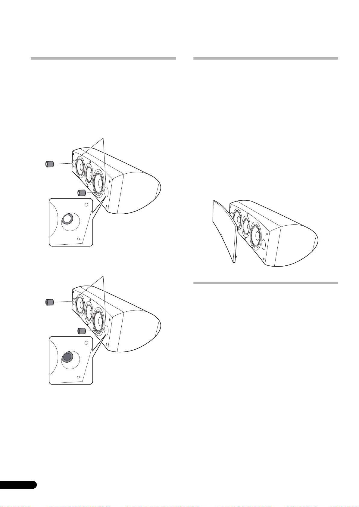
Aanvullende informatie
Gebruik van de schuimpluggen
Bij dit apparaat worden schuimpluggen geleverd die u kunt
gebruiken voor het instellen van het volume van het basgeluid. Om
de schuimpluggen te gebruiken, steekt u deze voorzichtig in de
basreflexpoorten aan de zijkanten van de luidspreker. Steek enkel
schuimplug A naar binnen of schuimplug A en B om het
gewenste geluid te verkrijgen.
Gebruik van enkel schuimplug A
Basreflexpoorten
Bevestigen/verwijderen van het
luidsprekerfront
Bij deze luidspreker wordt een luidsprekerfront geleverd dat u als
volgt kunt bevestigen en verwijderen:
1 Om het front te bevestigen, lijnt u de gaten in de
luidspreker uit met de pennen op het front en drukt dan het
front stevig tegen de luidspreker.
2 Om het front te verwijderen, pakt u met uw handen de
boven- en onderrand van het front aan de linkerkant vast en
trekt het front dan voorzichtig naar u toe om het linker
gedeelte van het front los te maken van de luidspreker.
3 Breng uw handen vervolgens naar het midden van het
front en trek opnieuw voorzichtig de boven- en onderrand
naar u toe om het middelste gedeelte los te maken.
4 Pak tenslotte de boven- en onderrand van het front aan
de rechterkant vast en trek het front voorzichtig naar u toe
om het resterende gedeelte van het front los te maken van
de luidspreker.
Gebruik van schuimplug A en B
Basreflexpoorten
Schoonmaken van de
luidsprekerbehuizing
Bij normaal gebruik is het voldoende als u de luidspreker af en toe
met een droge doek afveegt. Voor het verwijderen van hardnekkig
vuil kunt u de doek bevochtigen met een neutraal
reinigingsmiddel dat vijf- of zesmaal verdund is met water. Wring
de doek goed uit voordat u begint. Gebruik geen meubelwas of
sterke reinigingsmiddelen.
Gebruik nooit witte spiritus, benzine, insecticidenspray of andere
chemische middelen op of in de buurt van de luidsprekers, want
deze kunnen de afwerking aantasten.
10
Du
Page 53

Technische gegevens
Behuizing. . . . . . . . . . . . . . . . . . . . . . . . . . . . . . . . . . Basreflex, vloertype
(magnetisch afgeschermd)
Luidsprekersysteem . . . . . . . . . . . . . . . . . . . . . . . . . . . . . .3-wegsysteem
Woofer . . . . . . . . . . . . . . . . . . . . . . . . . . . . . . . . . . . . . . .16 cm conus x 2
Mid-tweeter . . . . . . . . . . . . . . . . . . . . . . . . . . .14 cm conus/3 cm koepel
Impedantie. . . . . . . . . . . . . . . . . . . . . . . . . . . . . . . . . . . . . . . . . . . . . . 6 Ω
Frequentiebereik . . . . . . . . . . . . . . . . . . . . . . . . . . . . . .34 Hz tot 100 kHz
Gevoeligheid . . . . . . . . . . . . . . . . . . . . . . . . . . . . . . . . . . 88,5 dB (2,83 V)
Maximaal ingangsvermogen . . . . . . . . . . . . . . . . . . . . . . . . . . . . . 160 W
Buitenafmetingen. . . . . . . . . .723 (B) mm x 263 (H) mm x 387 (D) mm
Gewicht . . . . . . . . . . . . . . . . . . . . . . . . . . . . . . . . . . . . . . . . . . . . . . . 28 kg
Bijgeleverde accessoires
Pennen. . . . . . . . . . . . . . . . . . . . . . . . . . . . . . . . . . . . . . . . . . . . . . . . . . . 3
Kurkschijfjes . . . . . . . . . . . . . . . . . . . . . . . . . . . . . . . . . . . . . . . . . . . . . . 3
Grote antislipkussentjes. . . . . . . . . . . . . . . . . . . . . . . . . . . . . . . . . . . . . 2
Kleine antislipkussentjes . . . . . . . . . . . . . . . . . . . . . . . . . . . . . . . . . . . . 4
Schuimpluggen (A,B). . . . . . . . . . . . . . . . . . . . . . . . . . . . . . . . . . . . . . . 2
Luidsprekervoet. . . . . . . . . . . . . . . . . . . . . . . . . . . . . . . . . . . . . . . . . . . . 1
Vulringen . . . . . . . . . . . . . . . . . . . . . . . . . . . . . . . . . . . . . . . . . . . . . . . . . 2
Veerring . . . . . . . . . . . . . . . . . . . . . . . . . . . . . . . . . . . . . . . . . . . . . . . . . . 1
Schroef (M5 x L40) . . . . . . . . . . . . . . . . . . . . . . . . . . . . . . . . . . . . . . . . . 1
Schroeven (M6 x L35) . . . . . . . . . . . . . . . . . . . . . . . . . . . . . . . . . . . . . . . 6
Front . . . . . . . . . . . . . . . . . . . . . . . . . . . . . . . . . . . . . . . . . . . . . . . . . . . . 1
Handleiding
Opmerking
Wijzigingen in ontwerp en technische gegevens voorbehouden,
zonder voorafgaande kennisgeving.
Magnetische afscherming
Deze luidsprekers zijn magnetisch afgeschermd. Afhankelijk van
de opstelling kan het echter toch voorkomen dat kleurvervorming
optreedt wanneer de luidsprekers te dicht bij het scherm van een
televisietoestel staan.
Als dit gebeurt, schakelt u de televisie uit en dan na 15 minuten tot
30 minuten weer in. Blijft het probleem bestaan, zet de
luidsprekers dan verder van de televisie vandaan.
is een handelsmerk dat op een product staat dat is
uitgerust met Pioneer’s Phase Control technologie. Met deze
technologie is een hoogwaardige geluidsweergave via elke
component mogelijk door verbetering van de totale faseaanpassing.
Uitgegeven door Pioneer Corporation.
Copyright © 2008 Pioneer Corporation.
Alle rechten voorbehouden.
Nederlands
11
Du
Page 54

Muchas gracias por la adquisición de este producto Pioneer.
Lea todo este manual de instrucciones para aprender a operar correctamente su modelo.
Después de haber leído las instrucciones, guarde el manual en un lugar seguro para poderlo consultar en el futuro.
Índice
Antes de comenzar
Contenido de la caja
Acerca de la serie EX
Tecnología que respalda el S-8EX . . . . . . . . . . . . . . . . . . . . . . . . . . 3
CST. . . . . . . . . . . . . . . . . . . . . . . . . . . . . . . . . . . . . . . . . . . . . . . . 3
Diafragma de grafito cerámico . . . . . . . . . . . . . . . . . . . . . . . . . . . 3
Diafragma de aleación de magnesio . . . . . . . . . . . . . . . . . . . . . . 4
Excitadores de graves. . . . . . . . . . . . . . . . . . . . . . . . . . . . . . . . . . 4
Construcción de la caja acústica de graves . . . . . . . . . . . . . . . . . 4
Redes de frecuencias de cruce. . . . . . . . . . . . . . . . . . . . . . . . . . . 4
Colaboración con Air Studios . . . . . . . . . . . . . . . . . . . . . . . . . . . . 4
Instalación y situación
Modo de instalación . . . . . . . . . . . . . . . . . . . . . . . . . . . . . . . . . . . . 5
Cuando lo instale directamente sobre el piso . . . . . . . . . . . . . . . . 5
Empleo de la base de altavoz suministrada . . . . . . . . . . . . . . . . . 5
Empleo del soporte de altavoz Pioneer CP-7EX. . . . . . . . . . . . . . . 6
Selección del lugar de colocación de los sistemas de altavoces. . 6
Conexiones
Conexión al amplificador. . . . . . . . . . . . . . . . . . . . . . . . . . . . . . . . . 7
Conexión de los cables . . . . . . . . . . . . . . . . . . . . . . . . . . . . . . . . . . 7
Conexiones de un cable sencillo. . . . . . . . . . . . . . . . . . . . . . . . . . 8
Conexiones de dos cables . . . . . . . . . . . . . . . . . . . . . . . . . . . . . . 8
Conexiones para dos amplificadores . . . . . . . . . . . . . . . . . . . . . . 9
Información adicional
Empleo de los tapones de espuma . . . . . . . . . . . . . . . . . . . . . . . . 10
Empleo de los tapones de espuma A solamente. . . . . . . . . . . . . 10
Empleo de los tapones de espuma A y B . . . . . . . . . . . . . . . . . . 10
Colocación/extracción de la cubierta de rejilla . . . . . . . . . . . . . . . 10
Limpieza de la caja acústica . . . . . . . . . . . . . . . . . . . . . . . . . . . . . 10
Especificaciones . . . . . . . . . . . . . . . . . . . . . . . . . . . . . . . . . . . . . . 11
Antes de comenzar
• La impedancia nominal de este sistema de altavoces es de 6Ω.
Conecte el sistema de altavoces a un amplificador que tenga
una impedancia de carga de 6 Ω a 16 Ω (un modelo que tenga
inscrito “6 Ω – 16 Ω” en los terminales de salida de altavoces
del amplificador).
Para evitar daños en el sistema de altavoces debido a una
sobrecarga de entrada, tenga presente las precauciones
siguientes:
• No aplique potencia al sistema de altavoces si excede la
entrada máxima permisible.
• Cuando emplee un ecualizador gráfico para acentuar los
sonidos altos de la gama de agudos, no aplique un volumen
excesivo del amplificador.
• No trate de forzar a un amplificador de poca potencia para que
produzca altos volúmenes de sonido (se incrementaría la
distorsión armónica del amplificador, y podría dañarse el
altavoz).
Precaución: instalación
• Cuando coloque esta unidad, cerciórese de que quede fijada
con seguridad y no la ponga en lugares en los que pudiera
correr el peligro de caídas y causar heridas en caso de un
desastre natural (como pudiera ser un terremoto).
• No monte los altavoces en la pared ni en el techo. Podrían
caerse y ocasionar heridas.
• No instale los altavoces en una posición elevada ni en la
pared. La rejilla de altavoz, si se monta incorrectamente,
puede caerse y ocasionar daños o heridas personales.
• Desconecte la alimentación y desenchufe su equipo
audiovisual y consulte las instrucciones antes de conectar
componentes. Asegúrese de emplear unos cables de
conexión adecuados.
Precaución: durante la utilización
• No ponga el altavoz sobre una superficie inestable. Correría el
peligro de caídas, pudiendo ocasionar heridas y daños en el
equipo.
• No emplee el altavoz para emitir sonido distorsionado durante
largos períodos de tiempo. Correría el peligro de incendios.
• No se suba ni se siente encima del altavoz, y no permita que
los niños jueguen sobre el altavoz.
• No ponga objetos grandes ni pesados sobre el altavoz.
• No ponga objetos magnéticos, como puedan ser
destornilladores, ni piezas de hierro cerca del altavoz de
agudos ni del de sonidos medios. Puesto que los altavoces
emplean imanes potentes, pueden atraer los objetos
metálicos, pudiendo ocasionar heridas o daños en el
diafragma.
Si desea deshacerse de este producto, no lo mezcle con los residuos generales de su hogar. De conformidad con la legislación
vigente, existe un sistema de recogida distinto para los productos electrónicos que requieren un procedimiento adecuado de
tratamiento, recuperación y reciclado.
Las viviendas privadas en los estados miembros de la UE, en Suiza y Noruega pueden devolver gratuitamente sus productos electrónicos usados
en las instalaciones de recolección previstas o bien en las instalaciones de minoristas (si adquieren un producto similar nuevo).
En el caso de los países que no se han mencionado en el párrafo anterior, póngase en contacto con sus autoridades locales a fin de conocer el
método de eliminación correcto.
Al actuar siguiendo estas instrucciones, se asegurará de que el producto de desecho se somete a los procesos de tratamiento, recuperación y
reciclaje necesarios, con lo que se previenen los efectos negativos potenciales para el entorno y la salud humana.
2
Sp
K058_A_Sp
Page 55

Contenido de la caja
A
B
Pies de punta x 3
Acerca de la serie EX
La serie EX, que incorpora abundantes conocimientos
tecnológicos aplicados a los destacados altavoces Pioneer de
la serie TAD, ha sido desarrollada con el objetivo de crear el
mejor altavoz de este nivel de precios.
El diseño y la producción de la serie EX ha sido el resultado de un
esfuerzo internacional que representa lo más refinado de la
tecnología en altavoces de Pioneer.
Pastillas de corcho x 3
Pastillas antideslizantes grandes x 2
Pastillas antideslizantes pequeñas x 4
Tapones de espuma (A, B) x 2
Tecnología que respalda el S-8EX
CST
El excitador principal del sistema es el Transductor de fuente
coherente (CST), que se basa en la tecnología empleada en la
serie TAD. El diafragma del altavoz de agudos está montado
concéntricamente con respecto al ápice del cono del altavoz de
medios, y proporciona una fuente de un punto de sonido de
400 Hz a 100 kHz. El CST asegura un perfecto equilibrio del
espectro entre los sonidos directos y los reflejados que llega a los
oídos de los oyentes, ofreciendo un sonido más consistente en la
sala de audición y una capacidad mejorada de la imagen sonora.
Diafragma de grafito cerámico
El altavoz de agudos del CST incorpora un diafragma de grafito
cerámico que proporciona unas características incomparables de
potencia y absorción del sonido como ninguno de los demás
materiales actualmente empleados en sistemas de altavoces de
audio de primera clase. El poco peso y la excepcional potencia del
grafito cerámico se combinan para crear altavoces con una
resonancia del diafragma que puede alcanzar hasta niveles
inaudibles.
Velocidad (m/s)
Base de altavoz x 1
Arandelas x 2
Arandela de resorte x 1
Tornillo (M5 x L40) x 1
Tornillos (M6 x L35) x 6
Rejilla x 1
Manual de instrucciones
18 000
16 000
14 000
12 000
10 000
8 000
6 000
4 000
Grafito cerámico
Aluminio
Berilio
Aleación de boro
Carbón cerámico
Papel
Titanio
Español
2 000
0
0,005 0,015
0,025
Pérdida interna
3
Sp
Page 56

Diafragma de aleación de magnesio
El altavoz de la gama media de la serie CST incorpora un
diafragma de aleación de magnesio que se destaca por su poco
peso y alta pérdida interna, y proporciona una excelente
transitoriedad y mínimo colorido de los sonidos de la gama de
frecuencias medias.
Excitadores de graves
El excitador de graves ilustrado abajo forma los cimientos del
sistema de altavoces S-8EX. La potencia del excitador es el
resultado del material compuesto de aramida/carbón, creado
originalmente durante el desarrollo del S-1EX, que se emplea en
su diafragma. Se ha incorporado la tecnología exclusiva de
Pioneer en circuitos magnéticos LDMC para conservar la
linealidad desde los niveles bajos a los altos y para minimizar la
distorsión.
Redes de frecuencias de cruce
Las redes de frecuencias de cruce emplean sólo los mejores
componentes. Las bobinas de núcleo de aire, los resistores no
inductivos y los capacitores de película en el paso de la señal han
sido todos seleccionados con mucho cuidado y han sido
optimizados para el excitador CST para producir la mayor
transparencia de la señal. Los excitadores de graves emplean
inductores de núcleo de chapa de acero al silicio que minimizan
la distorsión y la pérdida durante la transferencia de la energía.
Todos los componentes están directamente conectados a sus
materiales de conexión respectivos, en lugar de estarlo a una
tarjeta de circuito impreso, permitiendo de este modo conseguir
la pérdida mínima y el máximo rendimiento.
Colaboración con Air Studios
Desde que George Martin lo estableció in 1969 en Londres, Air
Studios de Inglaterra se ha ganado un reconocimiento
indiscutible de muchos artistas que lo consideran como el mejor
estudio de grabación del mundo. El sello de Air Studios que fue
otorgado al S-8EX indica que estos altavoces son capaces de
producir el sonido de alta calidad que buscan los mejores
creadores de sonido del mundo.
Construcción de la caja acústica de graves
La forma única del S-8EX se basa en una necesidad lógica. Para
poder sincronizar el tiempo de llegada del sonido desde el CST y
los dos excitadores de graves, cada excitador está montado sobre
un deflector que sirve para crear una delicada curva conocida
como la “curva de precisión” (vea la ilustración siguiente). Este
deflector, que consta de un MDF (tablero de fibra de densidad
media) de 65 mm de espesor, es además lo suficientemente fuerte
para contener la fuerza de los excitadores. Adicionalmente, el
paso de los graves se ha formado en un bloque muy grueso de
MDF, con lo que se consigue reducir el ruido del viento y se
producen unos sonidos graves claros y profundos.
Curva de precisión
4
Sp
Page 57

Instalación y situación
Importante
Modo de instalación
Seleccione la configuración de instalación que desee entre las
siguientes.
Cuando lo instale directamente sobre el piso
Emplee los pies de punta suministrados cuando desee instalar el
altavoz directamente sobre la superficie del piso.
Instalación
1 Gire los pies de punta para introducirlos en las roscas de
las tres piezas metálicas roscadas (M6) empotradas en la
parte inferior del altavoz, y enrósquelos con seguridad.
Pie de punta
Empleo de la base de altavoz suministrada
Cuando utilice la base de altavoz suministrada, no será necesario
emplear los pies de punta suministrados.
Instalación
1 Fije las pastillas antideslizantes (pequeñas) en las cuatro
posiciones de la parte inferior de la base.
Pastillas antideslizantes pequeñas
2 Fije las pastillas antideslizantes (grandes) suministradas
en las dos posiciones de la superficie superior de la base de
altavoz.
Parte inferior
del altavoz
2 Pongas las pastillas de corcho en los puntos de los tres
pies de punta golpeándolas al dejar apoyado el altavoz sobre
su base.
3 Ponga el altavoz encima de las pastillas de corcho.
Si no emplea las pastillas de corcho para colocar los
altavoces, es posible que los pies de punta causen
daños en el piso. Le recomendamos que emplee las
pastillas de corcho si se propone utilizar los pies de
punta.
• Puesto que esta unidad pesa unos 28 kg, es muy peligroso
intentar ajustar la tuerca del pie de punta mientras se tiene
inclinado el altavoz. Asegúrese de poner la unidad sobre un
lugar blando (como pueda ser una manta) para que no se
dañe el piso, y de efectuar la instalación entre dos personas
como mínimo.
Pastillas antideslizantes g
3 Ponga el altavoz encima de la base.
El empleo de la base de altavoz suministrada permite el ajuste
preciso del ángulo del altavoz.
Base del
altavoz
Importante
• Cuando utilice la base de altavoz suministrada, no fije el
altavoz en su posición con los tornillos. El el altavoz podría
caerse y ocasionar heridas.
randes
Español
5
Sp
Page 58

Empleo del soporte de altavoz Pioneer CP-7EX
Para emplear el soporte CP-7EX, debe colocarse la base de altavoz
suministrada a los pilares del soporte del CP-7EX. Monte los
soportes como se muestra a continuación.
Instalación
1 Extraiga el material de embalaje de los orificios de
tornillos avellanados que hay en la base de altavoz.
Selección del lugar de colocación de los sistemas de
altavoces
La situación dentro de la sa la de audición ten drá un gran i mpacto
en el rendimiento general del sistema de altavoces S-8EX en
términos de función de los graves, precisión del tono, y de
creación de la imagen sonora. Todas las salas son distintas, por lo
que esta sección lo explica sólo a modo de guía. Las pruebas
realizadas en la misma sala darán los mejores resultados.
Emplee la gráfica siguiente como guía para determinar la
situación óptima de los altavoces.
30 cm a 60 cm
2 Fije la base del altavoz a los pilares del soporte del
CP-7EX.
Emplee solamente los tornillos suministrados (M6 x L35).
Tornillos (M6 x L35)
Base del
altavoz
Pilares del soporte
Base del soporte
CP-7EX
3 Fije las pastillas antideslizantes (grandes).
4 Empleando los tornillos suministrados (M5 x L40), la
arandela de resorte y la arandela, fije el altavoz al soporte.
Para ayudar mejor a que no se caiga el altavoz, emplee
solamente los tornillos suministrados para fijar el altavoz al
soporte del altavoz. Con respecto a los detalles, consulte las
instrucciones suministradas con el soporte de altavoz CP-7EX.
Altavoz
delantero
.
Altavoz central
Posición de audición
Altavoz
delantero
Importante
• No ponga los altavoces en un lugar donde puedan quedar
bajo la luz directa del sol, y tampoco cerca de estufas o
acondicionadores de aire. Podría producirse deformación y
decoloración de la caja acústica y podrían dañarse los
altavoces.
• Pioneer no se hace responsable por ningún tipo de daño
debido al montaje y a la instalación inadecuados, al refuerzo
insuficiente, a la utilización indebida del producto, a desastres
naturales, etc.
Arandela de resorte
6
Sp
Pastillas antideslizantes grandes
Arandelas
Tornillo (M5 x L40)
Page 59

Conexiones
Conexión al amplificador
Este altavoz no se suministra con los cables de altavoz utilizados
para la conexión a un amplificador. Tenga en cuenta los factores
siguientes cuando seleccione los cables de altavoz para
aprovechar al máximo el rendimiento de su sistema de altavoces:
• Emplee un cable de gran calibre, y de la mínima longitud
necesaria.
• Los cables tienen características distintas. Recuerde lo
siguiente cuando utilice cualquier tipo de cables.
• Seleccione cables de la mínima resistencia posible, y
asegúrese de que las conexiones de los cables al amplificador
y al altavoz sean firmes y sólidas.
PRECAUCIÓN
Por estos terminales de altavoz circula tensión ACTIVA
que es PELIGROSA. Para evitar el peligro de descargas
eléctricas al conectar o desconectar los cables de
altavoz, desenchufe el cable de alimentación antes de
tocar las partes de los cables que no están aisladas.
D3-4-2-2-3_A_Sp
Conexión de los cables
1 Desconecte la alimentación del amplificador.
2 Conecte el extremo de un cable a los terminales de
entrada (inferiores) de la parte posterior. En cuanto a la
polaridad de los terminales, el rojo es positivo (+) y el negro
es negativo (–).
3 Conecte el otro extremo del cable a los terminales de
salida de altavoz en el amplificador, en el canal asignado a al
altavoz y manteniendo la polaridad (para más detalles al
respecto, consulte el manual de instrucciones del
amplificador).
Barra cortocircuitadora
Terminal rojo (+)
Terminal negro
(–)
• Tome los bornes de tapa de los terminales de entrada
inferiores y gírelos hacia la izquierda, inserte los cables de
altavoz en los orificios de los terminales, y apriete luego los
bornes para fijar la barra cortocircuitadora y los cables.
• También podrá conectar los terminales del altavoz con una
clavija de punta cónica. Cuando emplee una clavija de punta
cónica, no se olvide de quitar la tapa de la punta del terminal
de entrada.
• Después de haber efectuado la conexión tire ligeramente del
cable para asegurar la seguridad y solidez de la conexión. Las
conexiones defectuosas pueden ocasionar ruido e
interrupción del sonido.
• Si los hilos de los cables salen de los terminales y entran en
contacto entre sí, el amplificador recibirá una carga adicional
excesiva. Esto puede hacer que el amplificador deje de
funcionar y incluso pueda dañarse.
Sp
Español
7
Page 60
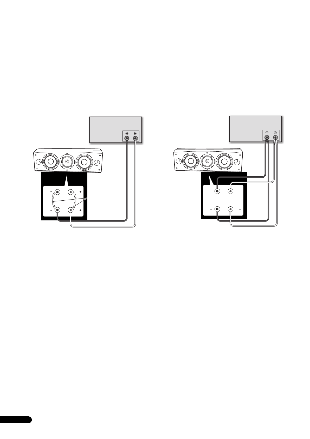
Conexiones de un cable sencillo
Para las conexiones de un cable sencillo, conecte las secciones
de frecuencias medias a altas y la de frecuencias bajas de la red
de frecuencias de cruce con el enlace de cortocircuito
suministrado con esta unidad, y luego conecte el cable (+) desde
su amplificador a uno de los bornes de unión rojos y el cable (–)
desde el amplificador a uno de los bornes de unión negros, como
se muestra a continuación.
Conexiones de dos cables
En una conexión de dos cables, enchufe independientemente los
altavoces desde el amplificador a sus clavijas respectivas de altas
y bajas frecuencias. De este modo el excitador CST y los
excitadores de graves se conectan independiente y directamente
al amplificador, otorgándole la libertad de optimizar el tipo de
cable para cada uno de los excitadores. Conecte un juego de
cables al juego inferior de los bornes de unión (red específica de
excitadores de graves). Luego, conecte un segundo juego de
cables a los bornes de unión superiores (red específica de
excitadores de CST). Después, conecte ambos juegos de cables a
los terminales correspondientes del amplificador. Tenga cuidado
para conectar ambos cables (+) a los terminales (+) del
amplificador y ambos cables (–) a los terminales (–) del
amplificador, como se muestra a continuación.
(Sólo se muestra un canal)
Amplificador
(trasero)
SPEAKERS OUTPUT
Altavoz
HF
HF
Conexión del
enlace de
LF
LF
cortocircuito
Altavoz (trasero): Panel de entrada
(Sólo se muestra un canal)
Amplificador
(trasero)
SPEAKERS OUTPUT
Altavoz
HF
LF
HF
LF
Altavoz (trasero): Panel de entrada
8
Sp
Page 61

Conexiones para dos amplificadores
Precaución
El sistema de dos amplificadores proporciona el mejor rendimiento cuando se emplean amplificadores exclusivos para las secciones de las
bajas frecuencias y para la de las frecuencias medias a altas.
Pueden efectuarse dos configuraciones, que son las de dos amplificadores en horizontal y vertical.
Extraiga los enlaces de cortocircuito antes de conectar los cables de altavoz en conexiones de dos amplificadores.
Si no lo hace así, pueden producirse daños en los amplificadores.
Dos amplificadores en vertical
Con esta configuración, se emplean amplificadores estéreo
idénticos para cada sistema de altavoces. Un canal de cada
amplificador excita la sección de bajas frecuencias y el otro canal
excita la sección de altas frecuencias, como se muestra a
continuación.
Conecte un juego de cables y el canal de amplificador al juego
inferior de los bornes de unión (red específica de excitadores de
graves).
Luego, conecte un segundo juego de cables y el otro canal de
amplificador a los bornes de unión superiores (red específica de
excitadores de CST).
Tenga cuidado para conectar ambos cables (+) a los terminales
(+) del amplificador y ambos cables (–) a los terminales (–) del
amplificador.
Preamplificador (trasero)
OUTPUT
(Sólo se muestra un canal)
OUTPUT
(Adaptador en Y de
venta en los
establecimientos
del ramo)
Amplificador
INPUT
de potencia
(trasero)
SPEAKERS OUTPUT
Ch.1 Ch.2
INPUT
Dos amplificadores en horizontal
Con esta configuración, podrá emplear amplificadores estéreo
distintos para las secciones de bajas y de altas a medias
frecuencias del sistema de altavoces (es decir, amplificadores de
válvulas para las altas frecuencias y de estado sólido para las
bajas frecuencias). Cana canal de un amplificador excita la
sección de bajas frecuencias de cada sistema de altavoces y cada
canal del otro amplificador excita la sección de frecuencias altas
a medias, como se muestra a continuación.
Este método requiere que ambos amplificadores tengan la misma
ganancia; de lo contrario, se percibirá un desequilibrio entre la
reproducción de las frecuencias bajas y la de las frecuencias
medias a altas por el sistema de altavoces. Si tiene alguna duda,
consulte al distribuidor de su localidad.
Preamplificador (trasero)
OUTPUTOUTPUT
(Sólo se muestra un canal)
Amplificador de
potencia (trasero)
(altas frecuencias)
SPEAKERS OUTPUT
(Adaptador en Y de venta
en los establecimientos
del ramo)
Amplificador de
INPUT
potencia (trasero)
(bajas frecuencias)
(Sólo se muestra un canal)(Sólo se muestra un canal)
INPUT
SPEAKERS OUTPUT
HF
LF
HF
Altavoz (trasero):
Panel de entrada
LF
Altavoz (trasero):
Panel de entrada
Altavoz
HF
LF
Altavoz
HF
LF
Español
9
Sp
Page 62

Información adicional
Empleo de los tapones de espuma
Esta unidad está provista de tapones de espuma que son útiles
para ajustar el volumen del sonido de los graves. Para emplearlos,
ponga con cuidado los tapones de espuma en los orificios de
reflejo de graves de uno de los lados del altavoz. Inserte sólo el
tapón de espuma A, o ambos tapones de espuma A y B para
conseguir el sonido deseado.
Empleo de los tapones de espuma A solamente
Orificios de reflejo de graves
Colocación/extracción de la cubierta
de rejilla
Este sistema de altavoces se sirve con cubiertas de rejilla que
pueden colocarse y extraerse de la forma siguiente:
1 Para colocar la cubierta de la rejilla, alinee los orificios del
altavoz con los apéndices de la rejilla, y empuje firmemente.
2 Para extraer la cubierta de la rejilla, tómela por los bordes
superior e inferior de la cubierta de la rejilla del lado
izquierdo con las dos manos, y tire con cuidado hacia usted
para separar del altavoz la parte izquierda de la cubierta de
la rejilla.
3 Luego, mueva las manos a la parte intermedia de la
cubierta de la rejilla y tire con cuidado otra vez de los bordes
superior e inferior hacia usted para separar la parte
intermedia.
4 Finalmente, tome los bordes superior e inferior de la
cubierta de la rejilla por el lado derecho y tire con cuidado
hacia usted para separar del altavoz la parte que queda de la
cubierta de la rejilla.
Empleo de los tapones de espuma A y B
Orificios de reflejo de graves
Limpieza de la caja acústica
En condiciones normales de utilización, emplee un paño seco
para frotar la superficie y mantener limpias las cajas acústicas. Si
es necesario, límpielas con un paño humedecido en un
detergente neutro diluido en cinco o seis partes de agua, y
enjuáguelo bien. No emplee cera para muebles ni detergentes.
No utilice nunca, ni en la unidad como cerca de ella, disolventes,
bencina, pulverizadores de insecticida u otros productos
químicos, ya que estos productos podrían corroer la superficie.
10
Sp
Page 63

Especificaciones
Tipo. . . . . . . . . . . . . . . . . . . . Tipo sobre el piso con reflexión de graves
(con protección magnética)
Configuración . . . . . . . . . . . . . . . . . . . . . . . . . . . . . . . . . . . . . . . . . .3 vías
Altavoz de graves . . . . . . . . . . . . . . . . . . . . . . . . . . . .Cono de 16 cm x 2
Altavoz de medios. . . . . . . . . . . . . . . . . . Cono de 14 cm/domo de 3 cm
Impedancia . . . . . . . . . . . . . . . . . . . . . . . . . . . . . . . . . . . . . . . . . . . . . 6 Ω
Respuesta en frecuencia . . . . . . . . . . . . . . . . . . . . . . . . 34 Hz a 100 kHz
Sensibilidad. . . . . . . . . . . . . . . . . . . . . . . . . . . . . . . . . . . 88,5 dB (2,83 V)
Potencia de entrada máxima. . . . . . . . . . . . . . . . . . . . . . . . . . . . . 160 W
Dimensiones exteriores . . 723 (An) mm x 263 (Al) mm x 387 (Prf) mm
Peso . . . . . . . . . . . . . . . . . . . . . . . . . . . . . . . . . . . . . . . . . . . . . . . . . . 28 kg
Accesorios suministrados
Pies de punta . . . . . . . . . . . . . . . . . . . . . . . . . . . . . . . . . . . . . . . . . . . . . 3
Pastillas de corcho . . . . . . . . . . . . . . . . . . . . . . . . . . . . . . . . . . . . . . . . . 3
Pastillas antideslizantes grandes . . . . . . . . . . . . . . . . . . . . . . . . . . . . . 2
Pastillas antideslizantes pequeñas . . . . . . . . . . . . . . . . . . . . . . . . . . . . 4
Tapones de espuma (A, B). . . . . . . . . . . . . . . . . . . . . . . . . . . . . . . . . . . 2
Base de altavoz . . . . . . . . . . . . . . . . . . . . . . . . . . . . . . . . . . . . . . . . . . . . 1
Arandelas . . . . . . . . . . . . . . . . . . . . . . . . . . . . . . . . . . . . . . . . . . . . . . . . 2
Arandela de resorte . . . . . . . . . . . . . . . . . . . . . . . . . . . . . . . . . . . . . . . . 1
Tornillo (M5 x L40). . . . . . . . . . . . . . . . . . . . . . . . . . . . . . . . . . . . . . . . . . 1
Tornillos (M6 x L35). . . . . . . . . . . . . . . . . . . . . . . . . . . . . . . . . . . . . . . . . 6
Rejilla . . . . . . . . . . . . . . . . . . . . . . . . . . . . . . . . . . . . . . . . . . . . . . . . . . . 1
Manual de instrucciones
Nota
Especificaciones y diseño sujetos a posibles cambios sin previo
aviso debido a mejoras del producto.
Protección magnética
El sistema del altavoz tiene protección magnética. Sin embargo,
dependiendo del lugar de instalación, pueden producirse
distorsiones de color en la pantalla del televisor si los sistemas de
altavoces están cerca de él.
Si así sucede, apague el televisor, y vuélvalo a encender después
de 15 minutos a 30 minutos. Si el problema persiste, aparte del
televisor el sistema de altavoces.
es una marca comercial que llevan los productos que
incorporan la tecnología de control de fase de Pioneer. Esta
tecnología permite la reproducción del sonido de alta calidad a
través de cada componente mediante la mejora de la
correspondencia de fase general.
Publicado por Pioneer Corporation.
Copyright © 2008 Pioneer Corporation.
Todos los derechos reservados.
11
Sp
Español
Page 64

Obrigado por ter adquirido este produto Pioneer.
Leia por favor estas instruções de utilização na sua totalidade para ficar a saber como operar adequadamente o seu aparelho.
Depois de terminar a leitura destas instruções, guarde-as num local seguro para referência futura.
Índice
Antes de começar
O que encontra na caixa
Sobre a série EX
Tecnologia por detrás do S-8EX. . . . . . . . . . . . . . . . . . . . . . . . . . . . 3
CST. . . . . . . . . . . . . . . . . . . . . . . . . . . . . . . . . . . . . . . . . . . . . . . . 3
Diafragmas de Grafite Cerâmica. . . . . . . . . . . . . . . . . . . . . . . . . . 3
Diafragmas de Liga de Magnésio . . . . . . . . . . . . . . . . . . . . . . . . . 4
Unidades de Graves . . . . . . . . . . . . . . . . . . . . . . . . . . . . . . . . . . . 4
Construção da Caixa de Graves . . . . . . . . . . . . . . . . . . . . . . . . . . 4
Redes de Crossover . . . . . . . . . . . . . . . . . . . . . . . . . . . . . . . . . . . 4
Colaboração com Air Studios . . . . . . . . . . . . . . . . . . . . . . . . . . . . 4
Instalação e Disposição
Como instalar . . . . . . . . . . . . . . . . . . . . . . . . . . . . . . . . . . . . . . . . . 5
Quando instalar directamente no chão. . . . . . . . . . . . . . . . . . . . . 5
Utilização da base de coluna fornecida . . . . . . . . . . . . . . . . . . . . 5
Utilização do suporte de coluna Pioneer CP-7EX . . . . . . . . . . . . . 6
Escolha do local onde colocar os sistemas de colunas . . . . . . . . 6
Ligações
Ligação a um amplificador . . . . . . . . . . . . . . . . . . . . . . . . . . . . . . . 7
Ligação dos cabos . . . . . . . . . . . . . . . . . . . . . . . . . . . . . . . . . . . . . 7
Ligações de um fio único . . . . . . . . . . . . . . . . . . . . . . . . . . . . . . . 8
Ligações de bi-cablagem . . . . . . . . . . . . . . . . . . . . . . . . . . . . . . . 8
Ligações de bi-amplificação . . . . . . . . . . . . . . . . . . . . . . . . . . . . . 9
Outra Informação
Utilização das cavilhas de espuma . . . . . . . . . . . . . . . . . . . . . . . . 10
Utilização das cavilhas A apenas . . . . . . . . . . . . . . . . . . . . . . . . 10
Utilização de ambas as cavilhas A e B . . . . . . . . . . . . . . . . . . . . 10
Colocar/retirar a grelha de cobertura . . . . . . . . . . . . . . . . . . . . . . 10
Limpeza da caixa das colunas. . . . . . . . . . . . . . . . . . . . . . . . . . . . 10
Especificações . . . . . . . . . . . . . . . . . . . . . . . . . . . . . . . . . . . . . . . 11
Antes de começar
• A impedância nominal deste sistema de colunas é de 6 Ω.
Ligue o sistema de colunas a um amplificador com uma
impedância de carga entre 6 Ω e 16 Ω (um modelo com a
indicação “6 Ω – 16 Ω” afixada nos terminais de saída para as
colunas).
De modo a prevenir danos nas colunas resultantes de
sobrecarga na entrada, observe por favor as seguintes
precauções:
• Não forneça potência ao sistema de colunas para além da
entrada máxima permitida.
• Quando utilizar um equalizador gráfico para dar ênfase a sons
altos na faixa das altas frequências, não utilize um volume de
amplificação excessivo.
• Não force um amplificador de baixa potência a produzir altos
volumes de som (a distorção harmónica do amplificador
aumentará, além de poder danificar a coluna).
Precaução: instalação
• Quando instalar este aparelho, certifique-se que está
firmemente segurado, evitando zonas em que possa cair e
causar ferimentos em caso de desastres naturais (tais como
um tremor de terra).
• Não fixe estas colunas à parede ou ao tecto. Podem cair,
causando ferimentos.
• Não instale as as suas colunas sobre a cabeça, na parede ou
notecto. Se mal fixadas, a grelha das colunas pode cair,
causando danos e ferimentos.
• Desligue da tomada o seu equipamento audio-visual e
consulte o manual de instruções quando ligar os
componentes entre si. Certifique-se que utiliza os cabos de
ligação adequados.
Precaução: utilização
• Não coloque a coluna numa superfície instável. Pode tornarse perigosa em caso de queda, para além de danificar o
equipamento.
• Não utilize a coluna para produzir som distorcido durante
longos períodos de tempo. Tal pode resultar em incêndio.
• Não se sente nem se ponha em pé em cima das colunas. Não
deixe as crianças brincar com as colunas.
• Não coloque objectos grandes ou pesados sobre as colunas.
• Não coloque objectos magnéticos tais como chaves de
parafusos ou peças de ferro perto do tweeeter ou dos médios.
As colunas utilizam fortes magnetes, podendo atrair objectos,
causando ferimentos ou danificando o diafragma.
Se quiser deitar fora este produto, não o misture com o lixo comum. De acordo com a legislação, existe um sistema de recolha
separado para os equipamentos electrónicos fora de uso, que requerem tratamento, recuperação e reciclagem apropriados.
Os consumidores dos Estados-membros da UE, da Suíça e da Noruega podem entregar equipamentos electrónicos fora de uso em
determinadas instalações de recolha ou a um retalhista (se adquirirem um equipamento novo similar).
Nos países não mencionados acima, informe-se sobre o método de eliminação correcto junto das autoridades locais.
Ao fazê-lo estará a garantir que o produto que já não tem utilidade para si é submetido a processos de tratamento, recuperação e reciclagem
adequados, evitando-se assim potenciais efeitos negativos para o ambiente e a saúde humana.
2
Po
K058_A_Po
Page 65

O que encontra na caixa
A
B
Espigões x 3
Sobre a série EX
A série EX, incorporando o abundante know-how
tecnológico por detrás da série de colunas TAD, bandeira da
Pioneer, foi desenvolvida com o objectivo de criar a
derradeira coluna na sua gama de preços.
A concepção e produção da série EX resulta de um esforço
internacional que representa o melhor da tecnologia de colunas
Pioneer.
Almofadas de cortiça x 3
Almofadas anti-derrapantes grandes x 2
Almofadas anti-derrapantes pequenas x 4
Cavilhas de espuma (A,B) x 2
Tecnologia por detrás do S-8EX
CST
O mecanismo propulsor do sistema é Transdutor de Fonte
Coerente (CST) baseado na tecnologia utilizada no TAD. O
diafragma do tweeter está montado concentricamente com o
vértice do cone de médios e proporciona uma fonte sonora
pontual entre 400 Hz e 100 kHz. O CST assegura o equilíbrio
espectral perfeito entre o sons directos e os sons reflectidos que
chegam aos ouvidos do ouvinte, proporcionando um som mais
consistente em toda a câmara de audição e uma capacidade
imagética melhorada.
Diafragmas de Grafite Cerâmica
Os tweeters do CST apresentam diafragmas de grafite cerâmica
que proporcionam resistência de alto nível e características de
amortecimento praticamente sem rival entre todos os outros
materiais actualmente em utilização em sistemas de colunas
áudio de topo de gama. A leveza da grafite cerâmica e a sua
resistência excepcional, conjuntamente, criam colunas cuja
ressonância do diafragma pode ser levada muito para além da
faixa de audição.
Velocidade (m/s)
Base de coluna x 1
Anilhas x 2
Anilha de mola x 1
Parafuso (M5 x L40) x 1
Parafusos (M6 x L35) x 6
Grelha x 1
Manual de instruções
18 000
16 000
14 000
12 000
10 000
8 000
6 000
4 000
Grafite Cerâmica
Alumínio
Berílio
Liga da Boron
Carbono Cerâmico
Papel
Titânio
Português
2 000
0
0,005 0,015
0,025
Perda Interna
3
Po
Page 66

Diafragmas de Liga de Magnésio
Os médios do CST apresentam diafragma de liga de magnésio
cuja leveza característica e alta perda interna proporcionam
transição excelente e coloração mínima dos sons médios.
Unidades de Graves
O mecanismo propulsor de graves ilustrado abaixo serve de
fundação para o sistema de colunas S-8EX. A resistência do
mecanismo é o resultado do compósito Aramida/Carbono, criado
originalmente durante o desenvolvimento do S-1EX, que é
utilizado no seu diafragma. A tecnologia de circuito magnético
LDMC, exclusiva da Pioneer, foi incorporada de modo a preservar
a linearidade de níveis de saída, desde baixos até altos, e a
minimizar a distorção.
Construção da Caixa de Graves
A forma única do S-8EX é baseada numa necessidade lógica. De
modo a sincronizar o tempo de chegada do som proveniente do
CST e das duas unidades de graves, cada unidade é montada
sobre um deflector que serve para criar uma curva altamente
delicada conhecida com a “curva de precisão” (ver ilustração
abaixo). Fabricado com MDF (prancha de fibra de média
densidade) até 65 mm, este deflector é, além disso, forte
suficiente para conter a força propulsora das unidade de graves.
Além disso, o porto dos graves foi esculpido num bloco de MDF
extremamente espesso, resultando na redução de ruído de vento,
para um som límpido, profundo.
Redes de Crossover
As redes de crossover utilizam apenas os melhores componentes.
Bobinas com núcleo de ar, resistores não indutivos e capacitores
de filme no caminho do sinal foram todos cuidadosamente
escolhidos e optimizados para a unidade CST, de modo a
proporcionar a maior transparência ao sinal. Os mecanismos de
graves utilizam inductores com núcleo de placas de aço silicone
que minimizam a distorção e as perdas, durante a transferência
de energia. Todos os componentes estão ligados directamente ao
seu material de cablagem respectivo, ao invés de estarem ligados
a um circuito impresso, permitindo perdas minímas e um máximo
desempenho.
Colaboração com Air Studios
Desde a sua fundação por George Martin em 1969, Londres, o Air
Studios inglês adquiriu o respeito inequívoco por parte de
múltiplos artistas que o reconhecem como o principal estúdio de
gravação do mundo. O selo Air Studios que foi atribuído ao S-8EX
indica que estas colunas são capazes de produzir o som de alta
qualidade exigido pelos criadores de som mais exigentes do
mundo.
4
Po
Curva de precisão
Page 67

Instalação e Disposição
Importante
Como instalar
Seleccione o modo de instalação que pretende.
Quando instalar directamente no chão
Utilize os espigões fornecidos quando instalar a coluna
directamente na superfície do chão.
Instalação
1 Aparafuse os espigões nos orífícios dos três furos metal
roscados (M6) abertos na base das colunas. Aparafuse-os
firmemente.
Espigão
Utilização da base de coluna fornecida
Quando utilizar a base de coluna fornecida, não é necessário
utilizar os espigões fornecidos.
Instalação
1 Afixe as almofadas anti-derrapantes (pequenas) nos
quatro locais na base da base.
Almofadas anti-derrapantes pequenas
2 Afixe as bases anti-deslizantes (grandes) nas duas bases
sobre a superfície da base da coluna.
Base da
coluna
2 Coloque as almofadas de cortiça nas posições que as três
pontas dos espigões irão acertar quando a coluna estiver na
sua posição.
3 Coloque a coluna sobre as almofadas de cortiça.
Senão não utilizar as almofadas de cortiça quando
colocar as colunas, os espigões podem danificar o chão.
Se pretender utilizar os espigões, recomendamos
vivamente que utilize as almofadas de cortiça.
• Uma vez que este aparelho pesa cerca de 28 kg, é muito
perigoso tentar ajustar a porca do espigão inclinando o
aparelho. Certifique-se que coloca a coluna sobre uma
superfície macia (tal como um cobertor) de modo a não
danificar o chão, e que procede à instalação com pelo menos
duas pessoas.
Almofadas anti-de
3 Coloque a coluna sobre a base.
A utilização da base da coluna permite um ajuste preciso do
ângulo da coluna.
Base de
coluna
Importante
rrapantes grandes
Português
• Quando utilizar a base da coluna fornecida, não coloque a
coluna na sua posição com os parafusos. A coluna pode cair
e causar ferimentos.
5
Po
Page 68
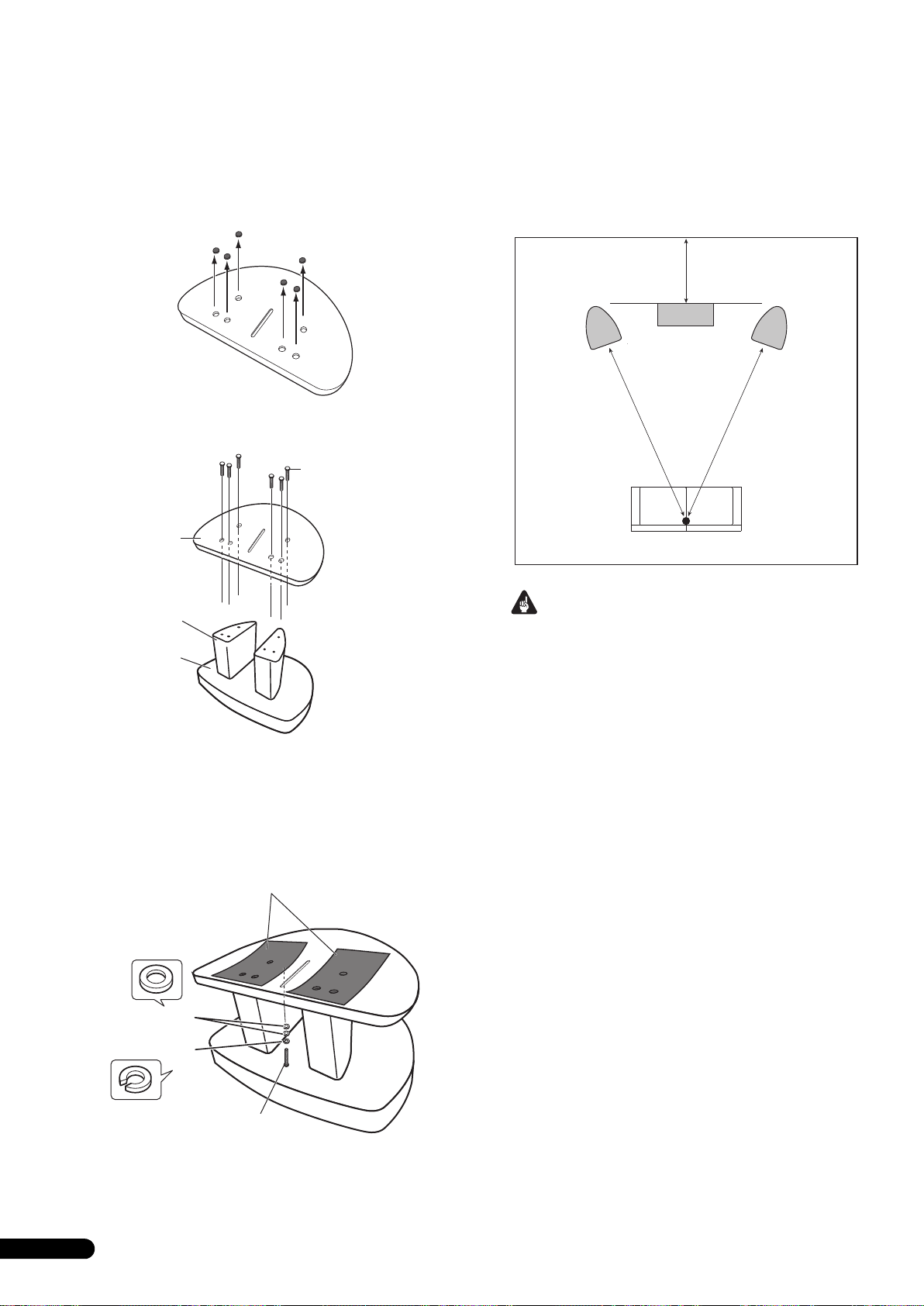
Utilização do suporte de coluna Pioneer CP-7EX
T
Para utilizar o suporte CP-7EX, a base de coluna fornecida precisa
estar fixa às hastes do suporte do CP-7EX. Monte o suporte como
abaixo demonstrado.
Instalação
1 Retire o material de embalar dos buracos dos parafusos
embutidos na base da coluna.
Escolha do local onde colocar os sistemas de colunas
A localização do sistema de colunas no quarto de audição tem um
grande impacto sobre o desempenho total do sistema de colunas
S-8EX, em termos de desempenho de baixos, precisão tonal, e
imagem sonora. Todos os quartos são diferentes; esta secção
serve apenas de guia. A experimentação no seu quarto dará
resultados óptimos.
Utilize o gráfico abaixo para determinar a localização óptima das
colunas.
30 cm a 60 cm
2 Fixe a base da coluna ao tronco do suporte do CP-7EX.
Utilize apenas os parafusos fornecidos (M6 x L35).
Parafusos (M6 x L35)
Base de
coluna
ronco do suporte
Base do suporte
CP-7EX
3 Afixe as almofadas anti-derrapantes (grandes).
4 Fixe a coluna à base utilizando dos parafusos fornecidos
(M5 x L40), a anilha de mola e a anilha.
Para ter a certeza que a coluna não cai, utilize apenas os
parafusos fornecidos para fixar o sistema da coluna ao
suporte da coluna. Para mais detalhes, consulte as instruções
fornecidas com o suporte de coluna CP-7EX.
Coluna
frontal
.
Coluna central
Posição de audição
Coluna
frontal
Importante
• Não coloque as colunas sob luz solar directa. Evite colocá-las
perto de aquecedores ou ar condicionados. Tal pode empenar
ou descolorar as caixas das colunas, ou danificar as colunas.
• A Pioneer não assume qualquer responsabilidade sobre
danos resultants da montagem, fixação deficiente, reforço
insuficiente, má utilização do produto, actos da natureza, etc.
Almofadas anti-derrapantes grandes
Anilhas
Anilha de mola
Parafuso (M5 x L40)
6
Po
Page 69

Ligações
Ligação a um amplificador
Esta coluna não inclui cabos de coluna para ligar a um
amplificador. Tome os seguintes factores em consideração
quando escolher os cabos das colunas, de modo a tirar o maior
partido do seu sistema de colunas:
• Utilize cabos de grande calibre se possível, e reduza o
comprimento dos cabos ao mínimo necessário.
• As características dos cabos variam. Lembre-se disto quando
escolher cabos.
• Seleccione os cabos com a menor resistência possível e
certifique-se que as ligações aos terminais das colunas e do
amplificador estão firmes e seguras.
CUIDADO
Estes terminais de coluna estão sob voltagem
PERIGOSA. Para evitar o risco de choque eléctrico ao
ligar ou desligar os cabos de coluna, desligue o cabo
de alimentação de energia antes de tocar em quaisquer
componentes não isolados.
D3-4-2-2-3_A_Po
Ligação dos cabos
1 Desligue a alimentação do seu amplificador.
2 Ligue os cabos de colunas aos terminais de entrada (em
baixo) na parte anterior da coluna. A polaridade dos
terminais de entrada é encarnado para o positivo (+) e preto
para o negativo (–).
3 Ligue as outras extremidades dos cabos aos terminais de
saída para colunas, no amplificador (para mais detalhes,
consulte o manual de utilizador do seu amplificador).
Conectores barra de curto-circuito
Terminal encarnado (+)
Terminal preto
(–)
• Segure os botões nos terminais de entrada inferiores e rodeos
para a esquerda (no sentido contrário aos ponteiros do
relógio). Insira os fios do cabo das colunas nos orifícios dos
postes do terminal. Aperte depois os botões para fixar a barra
de curto-circuito, bem como os fios.
• Pode também ligar os terminais da coluna utilizando uma
ficha banana. Quando utilizar uma ficha banana, certifique-se
de retirar a tampa na extremidade do terminal de entrada.
• Depois de ligar as fichas, puxe os cabos levemente para se
certificar que as extremidades destes se encontram ligadas
firmemente aos terminais. Ligações deficientes podem criar
ruído e interrupção no som.
• Se os fios dos cabos sairem dos terminais e entrarem em
contacto um com o outro, induzirão uma carga excessiva no
amplificador. Tal pode fazer com que o amplificador deixe de
funcionar, podendo mesmo danificar o amplificador.
Português
7
Po
Page 70

Ligações de um fio único
Para ligações de um só fio, ligue as secções de frequência médiaalta e baixa à rede de crossover utilizando a ligação de curtocircuito fornecida com a coluna. Ligue depois o fio (+) do
amplificador a um qualquer poste de ligação encarnado, e o fio (–
) do amplificador a um qualquer poste preto, tal como ilustrado
abaixo.
Ligações de bi-cablagem
Numa ligação de bi-cablagem, você liga independentemente nos
sistemas de colunas as fichas de alta e de baixa frequência do
amplificador. Tal resulta em que o propulsor CST e os propulsores
de baixos são ligados independente e directamente do
amplificador, oferecendo a possibilidade de optimizar o tipo de
cabo para um dos propulsores. Ligue um conjunto de cabos ao
conjunto de postes de ligação inferior (rede específica propulsora
de baixos). Ligue depois um segundo conjunto de cabos aos
postes de ligação superiores (rede específica CST). Depois, ligue
ambos os conjunto de cabos aos terminais apropriados no seu
amplificador. Tenha cuidado para ligar ambos os fios (+) aos
terminais (+) do amplificador, e ambos os fios (–) aos terminais (–
) do amplificador, tal como ilustrado abaixo.
(Apenas um canal ilustrado)
Amplificador
(parte de trás)
SPEAKERS OUTPUT
Coluna
HF
HF
Ligação
curto-circuito
LF
LF
Coluna (parte de trás): Painel de entrada
(Apenas um canal ilustrado)
Amplificador
(parte de trás)
SPEAKERS OUTPUT
Coluna
HF
LF
HF
LF
Coluna (parte de trás): Painel de entrada
8
Po
Page 71

Ligações de bi-amplificação
Precaução
A bi-amplificação permite o melhor desempenho quando utilizar amplificadores dedicados às secções baixas e médias-a-altas.
Há duas possíveis configurações, conhecidas com bi-amplificação horizontal e vertical.
Retire as ligações de curto-circuito antes de ligar os cabos de coluna numa ligações de bi-amplificação,
caso contrário pode causar danos nos amplificadores.
Bi-amplificação vertical
Para esta configuração são utilizados amplificadores estéreo
idênticos para cada sistema de colunas. Um canal de cada
ampificador fornece a secção de baixas frequências e o outro
fornece a secção de altas frequências, tal como ilustrado abaixo.
Ligue um conjunto de fios e o canal do amplificador ao conjunto
de postes de ligação inferior (rede específica de propulsão de
baixos).
Ligue um segundo par de fios e o outro canal do amplificador aos
postes de ligação superiores (rede específca CST).
Tome cuidado para ligar ambos os fios (+) aos terminais (+) do
amplificador e ambos os fio (–) aos terminais (–) do amplificador.
Pre-amplificador
(parte de trás)
OUTPUT
(Apenas um canal ilustrado)
OUTPUT
(Adaptador Y
disponível no
mercado)
Amplificador
de potência
INPUT
(parte de trás)
SPEAKERS OUTPUT
Ch.1 Ch.2
INPUT
Bi-amplificação horizontal
Com esta configuração pode utilizar diferentes amplificadores
estéreo para as secções de frequências baixa e média-a-alta do
sistema de colunas (por exemplo, amplificadores de válvulas para
altas frequências e de estado sólido para baixas frequências).
Cada canal de um amplificador fornece a secção de baixas
frequências, e cada canal do outro amplificador fornece a secção
de média-a-alta frequência, tal como ilustrado abaixo.
Este método requer que os dois amplificadores tenham o mesmo
ganho. De outro modo será perceptivel um desequilíbrio entre a
reprodução nas colunas das frequências baixas e médias-a-altas.
Em caso de dúvida, consulte o seu fornecedor habitual.
Pre-amplificador
(parte de trás)
OUTPUTOUTPUT
(Apenas um canal ilustrado)
Amplificador de
potência (parte de trás)
(Alta frequência)
SPEAKERS OUTPUT
(Adaptador Y disponível
no mercado)
Amplificador de
INPUT
potência (parte de trás)
(Baixa frequência)
(Apenas um canal ilustrado)(Apenas um canal ilustrado)
INPUT
SPEAKERS OUTPUT
HF
LF
HF
Coluna
(parte de trás):
Painel de entrada
LF
Coluna (parte de trás):
Painel de entrada
Coluna
HF
LF
Coluna
HF
LF
Português
9
Po
Page 72

Outra Informação
Utilização das cavilhas de espuma
Este aparelho vem equipado com cavilhas de espuma úteis para
ajustar o volume dos sons graves. Para as utilizar, coloque
suavemente as cavilhas de espuma nos portos de reflexão de
graves em ambos os lados da coluna. Insira apenas a cavilhas de
espuma A ou ambas as cavilhas de espuma A e B para obter o
som pretendido.
Utilização das cavilhas A apenas
Portos de reflexão de graves
Colocar/retirar a grelha de cobertura
Este sistema de colunas vem com grelhas de cobertura que
podem ser colocadas e retiradas, deste modo:
1 Para colocar a grelha de cobertura, alinhe os orifícios nas
colunas com espigões na grelha, e pressione firmemente.
2 Para retirar a grelha de cobertura, segure com as mãos o
lado esquerdo das extremidades superior e inferior da grelha
e puxe-a suavemente para si, de modo a separar da coluna o
lado esquerdo da grelha.
3 Depois desloque as mãos para a parte central da grelha e
novamente puxe-a suavemente para si, de modo a separar a
parte central da grelha.
4 Finalmente, segure o lado direito das extremidades
superior e inferior da grelha e puxe-a suavemente para si, de
modo a separar da coluna a última parte da grelha.
Utilização de ambas as cavilhas A e B
Portos de reflexão de graves
Limpeza da caixa das colunas
Em condições de utilização normais, a passagem com um pano
seco é suficiente para manter a caixa limpa. Se necessário limpe
com um pano embebido num detergente neutro diluído cinco ou
seis vezes em água, e torcido bem. Não utilize cera ou detergentes
para mobília.
Não utilize nunca diluentes, benzina, sprays insecticidas ou outro
produto químico neste ou próximo deste aparelho, pois tal
corroerá as superfícies.
10
Po
Page 73

Especificações
Caixa . . . . . . . . . . . . . . . . . . . . . . . .Tipo baixo-reflexo, assente no chão
(protegida magneticamente)
Configuração. . . . . . . . . . . . . . . . . . . . . . . . . . . . . . . . . . . . . . . . . . .3 vias
Altifalante de graves (Woofer) . . . . . . . . . . . . . . . . . . . . .16 cm cone x 2
Tweeter de médios . . . . . . . . . . . . . . Cone de 14 cm/abóbada de 3 cm
Impedância . . . . . . . . . . . . . . . . . . . . . . . . . . . . . . . . . . . . . . . . . . . . . 6 Ω
Resposta em frequência . . . . . . . . . . . . . . . . . . . . . . . . 34 Hz a 100 kHz
Sensibilidade. . . . . . . . . . . . . . . . . . . . . . . . . . . . . . . . . . 88,5 dB (2,83 V)
Potência máxima de entrada. . . . . . . . . . . . . . . . . . . . . . . . . . . . . 160 W
Dimensões exteriores. . . . . . . 723 (L) mm x 263 (A) mm x 387 (P) mm
Peso . . . . . . . . . . . . . . . . . . . . . . . . . . . . . . . . . . . . . . . . . . . . . . . . . . 28 kg
Acessórios fornecidos
Espigões . . . . . . . . . . . . . . . . . . . . . . . . . . . . . . . . . . . . . . . . . . . . . . . . . 3
Almofadas de cortiça . . . . . . . . . . . . . . . . . . . . . . . . . . . . . . . . . . . . . . . 3
Almofadas anti-derrapantes grandes . . . . . . . . . . . . . . . . . . . . . . . . . . 2
Almofadas anti-derrapantes pequenas. . . . . . . . . . . . . . . . . . . . . . . . . 4
Cavilhas de espuma (A,B) . . . . . . . . . . . . . . . . . . . . . . . . . . . . . . . . . . . 2
Base de coluna . . . . . . . . . . . . . . . . . . . . . . . . . . . . . . . . . . . . . . . . . . . . 1
Anilhas. . . . . . . . . . . . . . . . . . . . . . . . . . . . . . . . . . . . . . . . . . . . . . . . . . . 2
Anilha de mola . . . . . . . . . . . . . . . . . . . . . . . . . . . . . . . . . . . . . . . . . . . . 1
Parafuso (M5 x L40) . . . . . . . . . . . . . . . . . . . . . . . . . . . . . . . . . . . . . . . . 1
Parafusos (M6 x L35) . . . . . . . . . . . . . . . . . . . . . . . . . . . . . . . . . . . . . . . 6
Grelha . . . . . . . . . . . . . . . . . . . . . . . . . . . . . . . . . . . . . . . . . . . . . . . . . . . 1
Manual de instruções
Nota
Especificações e concepção sujeitas a possíveis modificações
sem aviso prévio, devido a melhoramentos.
Escudo magnético
Este sistema de colunas está magneticamente escudado. No
entanto, dependendo do local de instalação, pode ocorrer
distorção de cor se o sistema de colunas for colocado demasiado
perto do ecrã de um televisor.
Se tal acontecer, desligue o televisor e ligue-o novamente
15 minutos a 30 minutos depois. Se o problema persistir afaste as
colunas do televisor.
é um marca registada colocada num produto com
tecnologia Controlo de Fase Pioneer. Esta tecnologia permite uma
reprodução sonora de alto grau através de cada componente,
melhorando o emparelhamento geral de fases.
Publicado por Pioneer Corporation.
“Copyright” © 2008 Pioneer Corporation.
Todos os direitos reservados.
11
Po
Português
Page 74

Gratulerar till ditt inköp av denna Pioneer-produkt.
Läs noggrant igenom denna bruksanvisning, så att du vet hur du skall hantera högtalaren på rätt sätt.
När du har läst igenom bruksanvisningen, skall du förvara den på en säker plats för framtida bruk.
Innehåll
Innan du startar
Detta finns i kartongen
Om EX-serien
Teknologi bakom S-8EX. . . . . . . . . . . . . . . . . . . . . . . . . . . . . . . . . . 3
CST. . . . . . . . . . . . . . . . . . . . . . . . . . . . . . . . . . . . . . . . . . . . . . . . 3
Keramiskt grafitmembran. . . . . . . . . . . . . . . . . . . . . . . . . . . . . . . 3
Membran av magnesiumlegering. . . . . . . . . . . . . . . . . . . . . . . . . 4
Basdrivenheter . . . . . . . . . . . . . . . . . . . . . . . . . . . . . . . . . . . . . . . 4
Bashöljets konstruktion . . . . . . . . . . . . . . . . . . . . . . . . . . . . . . . . 4
Brytfrekvensnät. . . . . . . . . . . . . . . . . . . . . . . . . . . . . . . . . . . . . . . 4
Samarbete med Air Studios . . . . . . . . . . . . . . . . . . . . . . . . . . . . . 4
Installation och placering
Installation . . . . . . . . . . . . . . . . . . . . . . . . . . . . . . . . . . . . . . . . . . . 5
Vid placering direkt på golvet . . . . . . . . . . . . . . . . . . . . . . . . . . . . 5
Användning av det medföljande högtalarstödet . . . . . . . . . . . . . . 5
Användning av Pioneers högtalarstativ CP-7EX . . . . . . . . . . . . . . 6
Val av högtalarsystemets placering. . . . . . . . . . . . . . . . . . . . . . . . 6
Anslutningar
Anslutning till en förstärkare. . . . . . . . . . . . . . . . . . . . . . . . . . . . . . 7
Anslutning av kablarna . . . . . . . . . . . . . . . . . . . . . . . . . . . . . . . . . . 7
Anslutning med enkelkablar . . . . . . . . . . . . . . . . . . . . . . . . . . . . . 8
Anslutning med dubbla kablar . . . . . . . . . . . . . . . . . . . . . . . . . . . 8
Anslutning av två förstärkare till varje högtalare (bi-amping) . . . . 9
Övrig information
Användning av skumgummipropparna. . . . . . . . . . . . . . . . . . . . . 10
Användning av endast skummgummipropp A . . . . . . . . . . . . . . 10
Användning av både skumgummipropp A och B . . . . . . . . . . . . 10
Fastsättning/borttagning av grillskydden. . . . . . . . . . . . . . . . . . . . 10
Rengöring av högtalarhöljet . . . . . . . . . . . . . . . . . . . . . . . . . . . . . 10
Specifikationer . . . . . . . . . . . . . . . . . . . . . . . . . . . . . . . . . . . . . . . 11
Innan du startar
• Denna högtalares nominella impedans är 6 Ω. Anslut
högtalaren till en förstärkare med en belastningsimpedans i
omfånget från 6 Ω till 16 Ω (en modell där “6 Ω – 16 Ω” visas
intill högtalarutgången).
För att förhindra att högtalarsystemet skadas på grund av
överbelastad inmatning, skall du följa följande
säkerhetsföreskrifter:
• Mata inte uteffekt till högtalaren som överskrider den
maximalt tillåtna ingången.
• När du använder en grafisk equalizer för att betona kraftiga
diskantljud, skall du inte använda för hög ljudnivå för
förstärkaren.
• Försök inte att tvinga en lågeffektsförstärkare att mata ut
kraftiga ljudnivåer (förstärkarens harmoniska distorsion ökas
och du kan skada högtalaren).
Observera: Installation
• Vid placeringen av denna enhet skall du se till att den står
stadigt och undvika platser där den kan tippa över och orsaka
personskador vid någon typ av naturkatastrof (till exempel en
jordbävning eller en tornado).
• Sätt inte fast dessa högtalare på väggen eller i taket. De kan
falla ned och orsaka personskador.
• Montera inte högtalarna högt i taket eller på väggen. Om de
sätts fast på fel sätt, kan högtalargrillen falla ned och orsaka
materiella skador eller personskador.
• Stäng av och lossa din AV-utrustning från elnätet samt se i
bruksanvisningarna vid anslutning av apparater. Kontrollera
att du använder korrekta anslutningskablar.
Observera vid användning
• Ställ inte högtalaren på en ostadig yta. Den kan utgöra en fara
om den tippar över och detta kan också skada utrustningen.
• Använd inte högtalaren för utmatning av förvrängt ljud under
långa tidsperioder. Detta kan leda till fara för brand.
• Du får inte sitta eller stå på högtalaren och inte låta barn leka
på den.
• Placera inte stora eller tunga föremål ovanpå högtalaren.
• Lägg inte magnetiska föremål som till exempel skruvmejslar
eller delar av stål nära diskantelementet eller mellanregistret.
På grund av att högtalarna använder kraftiga magneter, kan
de dra till sig sådana föremål, vilket kan orsaka personskador
eller kan skada membranet.
Denna produkt får inte kastas tillsammans med vanligt hushållsavfall. Uttjänta elektronikprodukter skall enligt lag samlas in separat
för särskild hantering och återvinning.
I EU:s medlemsländer samt Schweiz och Norge får privata hushåll kostnadsfritt lämna in uttjänt elektronik på särskilda insamlingsställen och
återvinningscentraler eller hos en återförsäljare (vid köp av liknande produkt).
I övriga länder skall lokala myndigheter kontaktas för information om korrekt avfallshantering.
Härigenom kommer den kasserade produkten att samlas in, behandlas och återvinnas på det sätt som krävs för att minska negativ påverkan på
miljö och människors hälsa.
2
Sw
K058_A_Sw
Page 75

Detta finns i kartongen
A
B
Spetsar x 3
Om EX-serien
EX-serien, som utnyttjar den rika teknologiska know-how
som finns bakom Pioneers flaggskepp TAD-seriens
högtalare, utvecklades med syftet att skapa den bästa
tänkbara högtalaren i sin prisklass.
Konstruktionen och tillverkningen av EX-serien är resultatet av en
internationell strävan som representerar det allra bästa av
Pioneers högtalarteknologi.
Svenska
Korkdynor x 3
Stora glidskyddsdynor x 2
Små glidskyddsdynor x 4
Skumgummiproppar (A, B) x 2
Teknologi bakom S-8EX
CST
Systemets bärande drivenhet är Coherent Source Transducer
(CST), som utnyttjar den teknologi som används i TAD.
Diskantelementets membran har monterats koncentriskt inom
spetsen av mellanregistrets kon och ger en betonad ljudkälla från
400 Hz till 100 kHz. CST tillförsäkrar en perfekt spektral balans
mellan de direkta och reflekterade ljud som når fram till
lyssnarens öra, vilket skapar ett mera oföränderligt ljud i hela
lyssningsrummet och en förbättrad ljudbildsuppfattning.
Keramiskt grafitmembran
CST:s diskantelement har ett keramiskt grafitmembran som ger
styrka av toppnivå och dämpningsegenskaper som är praktiskt
taget oöverträffade jämfört med andra tillgängliga materiel som
idag används i högklassiga högtalarsystem. Den keramiska
grafitens lätthet och exceptionella styrka kombineras för att skapa
högtalare vars membranresonans kan pressas långt bortom deras
ljudomfång.
Ljudhastighet (m/s)
Högtalarstöd x 1
Brickor x 2
Fjäderbricka x 1
Skruv (M5 x L40) x 1
Skruvar (M6 x L35) x 6
Grill x 1
Bruksanvisning
18 000
16 000
14 000
12 000
10 000
8 000
6 000
4 000
2 000
Keramisk grafit
Aluminium
Beryllium
Borlegering
Keramisk carbon
Papper
Titan
0
0,005 0,015
0,025
Inner loss-frekvenskarakteristika
3
Sw
Page 76

Membran av magnesiumlegering
CST:s mellanregisterelement har ett membran av en
magnesiumlegering, vars karaktäristiska lätthet och höga inner
loss-frekvenskarakteristika bjuder på en utsökt utjämning och en
minimal färgning av mellanregistrets ljud.
Basdrivenheter
Den basdrivenhet som visas här nedan är grundstommen för
högtalarsystemet S-8EX. Drivenhetens styrka är resultatet av
materialkombinationen aramid/carbon, ursprungligen skapad
under utvecklingen av S-1EX, som används i dess membran.
Pioneers exklusiva LDMC magnetkretsteknologi har använts för
att bibehålla lineariteten från låga till höga utgångsnivåer samt för
att minimera distorsionen.
Bashöljets konstruktion
Den unika utformningen av S-8EX är baserad på logisk
nödvändighet. För att synkronisera ankomsttiden för ljud från CST
och de två basdrivenheterna, har varje drivenhet monterats på en
baffel som är till för att skapa en synnerligen delikat kurva som
kallas för “precisionskurvan” (se illustrationen här nedan). Denna
baffel, som är tillverkad av upp till 65 mm tjock MDF (Medium
Density Fiberboard), är dessutom tillräckligt kraftig för att
innesluta drivenheternas drivkraft. Dessutom har basporten
karvats ut ur ett mycket tjockt block av MDF, vilket resulterar i en
dämpning av vindbrus för att ge en klar och djup bas.
Brytfrekvensnät
Brytfrekvensnäten använder endast finast tänkbara komponenter.
Luftspolar, icke-induktiva resistorer och plastkondensatorer i
signalbanan har alla utvalts noggrant och optimerats för CSTdrivenheten, detta för att erbjuda bästa tänkbara
signaltransparens. Basdrivenheterna använder induktansspolar
med kärna av kiselstål som minimerar distorsion och förluster
under energiöverföringen. Alla komponenter har anslutits direkt
till sina respektive installationsmateriel, i stället för ett tryckt
kretskort, vilket möjliggör minimala förluster och maximala
prestanda.
Samarbete med Air Studios
Från dess etablering av George Martin år 1969 i London, har
Englands Air Studios gjort sig förtjänt av otvetydig respekt från
mängder av artister som värdesatt studion som världens främsta
inspelningsstudio. Sigillet från Air Studios som har tilldelats
S-8EX visar att dessa högtalare klarar av att producera det ljud
med toppkvalitet som krävs av världens yppersta ljudskapare.
4
Sw
Precisionskurva
Page 77

Installation och placering
Viktigt
Installation
Välj en av de följande installationstyperna.
Vid placering direkt på golvet
Använd de medföljande spetsarna när högtalaren placeras direkt
på ett golv.
Montering
1 Vrid in spetsarna i de tre nedsänkta gängade
metallinsatserna (M6) på högtalarens undersida så att de är
ordentligt fastsatta.
Spets
Användning av det medföljande högtalarstödet
Om du använder det medföljande högtalarstödet, behöver du inte
använda de medföljande spetsarna.
Svenska
Montering
1 Sätt fast de medföljande glidskyddsdynorna (små) på de
fyra angivna platserna på stödets undersida.
Små glidskyddsdynor
2 Sätt fast de medföljande glidskyddsdynorna (stora) på de
två angivna platserna på stödets översida.
Stora glidskyddsdynor
Högtalarens
undersida
2 Placera korkdynorna på de platser där de tre spetsarnas
ända kommer att hamna när högtalaren ställs ned.
3 Placera högtalaren ovanpå korkdynorna.
Om du inte använder korkdynorna vid uppställningen
av högtalarna, kan spetsarna skada underlaget. Om du
tänker använda spetsarna, rekommenderar vi att du
också använder korkdynorna.
• På grund av att den här enheten väger ca. 28 kg, är det mycket
farligt att försöka justera spetsmuttern medan du lutar
högtalaren. Var noga med att lägga enheten på något mjukt
(till exempel en filt) så att den inte skadar golvet och utför
installationen med minst två personer.
3 Placera högtalaren ovanpå stödet.
Om du använder det medföljande högtalarstödet, kan du
finjustera högtalarens vinkel.
Högtalarstöd
Viktigt
• Om du använder det medföljande högtalarstödet, skruva inte
fast högtalaren. Då kan högtalaren falla ned och orsaka
personskador.
5
Sw
Page 78

Användning av Pioneers högtalarstativ CP-7EX
För att kunna använda stativet CP-7EX, måste det medföljande
högtalarstödet sättas fast på pelarna för CP-7EX. Sätt ihop stativet
såsom visas här nedan.
Montering
1 Tag bort förpackningsmaterialet från de försänkta
skruvhålen i högtalarstödet.
Val av högtalarsystemets placering
Placeringen i lyssningsrummet har mycket stor betydelse för den
totala prestationen för högtalarsystemet S-8EX när det gäller
basprestanda, ljudets exakthet och ljudbilden. Alla rum är olika
och detta avsnitt är därför endast tänkt som en vägledning.
Experimentera i rummet tills du får optimalt resultat.
Använd bilden här nedan som vägledning för att fastställa den
bästa placeringen för högtalarna.
30 cm till 60 cm
2 Sätt fast högtalarstödet på pelarna för CP-7EX.
Använd endast de medföljande skruvarna (M6 x L35).
Skruvar (M6 x L35)
Högtalarstöd
Stativets pelare
Stativets bottenplatta
CP-7EX
högtalare
.
Främre
Mitthögtalare
Lyssningsposition
Främre
högtalare
Viktigt
• Placera inte högtalaren, där den kan utsättas för direkt solljus
och undvik att placera den nära värmeelement och
luftkonditionerare. Detta kan leda till att högtalarens hölje blir
skevt och missfärgat samt att högtalarelementen skadas.
• Pioneer tar inte på sig något som helst ansvar för skador som
uppstår på grund av ihopsättning, felaktig montering,
otillräcklig förstärkning, felaktig användning av stativet,
naturkatastrofer, etc.
3 Sätt fast glidskyddsdynorna (stora).
4 Använd de medföljande skruvarna (M5 x L40),
fjäderbrickan och brickan för att skruva fast högtalaren i
stativet.
För att hjälpa till att förhindra att högtalaren faller ned, skall du
endast använda de medföljande skruvarna för att skruva fast
högtalaren i högtalarstativet. Se anvisningarna som medföljer
högtalarstativet CP-7EX för ytterligare upplysningar.
Stora glidskyddsdynor
Brickor
Fjäderbricka
Skruv (M5 x L40)
6
Sw
Page 79

Anslutningar
Anslutning till en förstärkare
Till denna högtalare medföljer inga högtalarkablar för anslutning
till en förstärkare. Tag följande faktorer med i beräkningen när du
väljer högtalarkablar, så att du får ut mesta möjliga av ditt
högtalarsystem:
• Använd tjocka högtalarkablar om det är möjligt och håll
kablarna så korta som möjligt.
• Kablar har olika egenskaper. Kom ihåg detta när du använder
någon kabel.
• Välj kablar med så litet motstånd som möjligt och kontrollera
att kablarna till högtalarens och förstärkarens terminaler sitter
fast ordentligt.
VIKTIGT
Dessa högtalarkontakter är strömförande och
innehåller FARLIG SPÄNNING. För att minska risken för
elektrisk stöt när du ansluter eller drar ur
högtalarsladdarna ska nätkabeln dras ur innan någon
oisolerad del vidrörs.
D3-4-2-2-3_A_Sw
Anslutning av kablarna
1 Stäng av strömmen till förstärkaren.
2 Anslut högtalarkablarna till ingången (nedre) på
baksidan av högtalaren. Den röda ingångens polaritet är
positiv (+) och den svarta är negativ (–).
3 Anslut de andra ändarna av kablarna till förstärkarens
högtalarutgångar (för ytterligare upplysningar hänvisas till
förstärkarens bruksanvisning).
Kortslutningsstift
Röd terminal (+)
Svart terminal
(–)
• Fatta i knopparna på de nedre ingångarna och vrid dem åt
vänster (moturs), sätt in kablarnas kärntrådar i hålen i
terminalerna och drag därefter fast knopparna för att låsa fast
både kortslutningsstiftet och kärntrådarna.
• Du kan också ansluta till högtalarterminalerna med en
banankontakt. Vid användning av en banankontakt skall du
komma ihåg att ta bort kåpan vid spetsen av ingången.
• Efter anslutningarna skall du dra lätt i kablarna för att
kontrollera att kabeländarna sitter fast ordentligt i
terminalerna. Slarviga anslutningar kan leda till störningar
och ljudavbrott.
• Om kablarnas kärntrådar lossnar från terminalerna, så att
kärntrådarna kommer i beröring med varandra, skapar det en
för hög belastning på förstärkaren. Detta kan göra att
förstärkaren slutar att fungera och förstärkaren kan till och
med skadas.
Svenska
Sw
7
Page 80

Anslutning med enkelkablar
SPEAKERS OUTPUT
Kortslutningslänkens
anslutning
Högtalare (baksida): Ingångspanel
Förstärkare (baksida)
(Endast en kanal visas)
Högtalare
HF
HF
LF
LF
Vid anslutning med enkelkablar skall du ansluta delarna av
brytfrekvensnätet för mellanregister-till-diskant samt lågfrekvens
med den kortslutningslänk som medföljer denna enhet, och
därefter ansluta plusledningen (+) från din förstärkare till en av de
rödmärkta terminalerna och minusledningen (–) från din
förstärkare till en av de svartmärkta terminalerna på det sätt som
visas här nedan.
Anslutning med dubbla kablar
Vid anslutning med dubbla kablar ansluter du separat mellan
förstärkaren och respektive hög- och lågfrekvensuttag på
högtalarsystemet. Detta resulterar i att CST-drivenheten och
basdrivenheterna ansluts separat direkt till förstärkaren, vilket ger
dig möjlighet att välja bästa tänkbara kabeltyp för var och en av
drivenheterna. Anslut en kabelsats till den nedre gruppen av
terminaler (specifikt nät för basdrivenhet). Anslut därefter en
andra kabelsats till den övre gruppen av terminaler (CST-specifikt
nät). Därefter skall de båda kabelsatserna anslutas till korrekta
terminaler på din förstärkare. Var noga med att ansluta båda
pluskablarna (+) till förstärkarens plusterminaler (+) och båda
minuskablarna (–) till förstärkarens minusterminaler (–), såsom
visas här nedan.
(Endast en kanal visas)
Förstärkare (baksida)
SPEAKERS OUTPUT
Högtalare
HF
LF
HF
LF
Högtalare (baksida): Ingångspanel
8
Sw
Page 81

Anslutning av två förstärkare till varje högtalare (bi-amping)
Observera
Dubbla förstärkare ger bästa tänkbara prestanda genom användning av speciella förstärkare för delarna för lågfrekvens och mellanregistertill-högfrekvens.
Det finns två tänkbara konfigurationer, vanligtvis kallade horisontal och vertikal bi-amping.
Tag bort kortslutningslänkarna innan du ansluter högtalarkablar till två förstärkare för varje högtalare (bi-amping).
Om du inte gör det kan dina förstärkare skadas.
Vertikal bi-amping
Med denna konfiguration använder du identiskt lika
stereoförstärkare för varje högtalare. En kanal för varje förstärkare
driver lågfrekvensdelen och den andra kanalen driver
högfrekvensdelen, såsom visas här nedan.
Anslut en kabelsats och en förstärkarkanal till den nedre gruppen
av terminaler (specifikt nät för basdrivenhet).
Anslut därefter en andra kabelsats och den andra
förstärkarkanalen till den övre gruppen av terminaler (CSTspecifikt nät).
Var noga med att ansluta båda pluskablarna (+) till förstärkarens
plusterminaler (+) och båda minuskablarna (–) till förstärkarens
Horisontal bi-amping
Med denna konfiguration kan du använda olika stereoförstärkare
för högtalarens delar för lågfrekvens och mellanregister-tillhögfrekvens (till exempel rörförstärkare för höga frekvenser och
halvledarförstärkare för låga frekvenser). Varje kanal för ena
förstärkaren driver lågfrekvensdelen för varje högtalare och varje
kanal för den andra förstärkaren driver delen för mellanregistertill-högfrekvens, såsom visas här nedan.
Denna metod kräver att båda förstärkarna har samma
förstärkning; annars hörs en obalans mellan återgivningen av
lågfrekvens och mellan-till-högfrekvens från högtalarna. Kontakta
din lokala återförsäljare, om du är tveksam.
minusterminaler (–).
Förförstärkare (baksida)
OUTPUT
(Endast en kanal visas)
OUTPUT
Y-adapter (köpes i
fackhandeln)
Effektförstärkare
INPUT
(baksida)
SPEAKERS OUTPUT
Ch.1 Ch.2
INPUT
Förförstärkare (baksida)
(Endast en kanal visas)
Effektförstärkare
(baksida)
(högfrekvens)
SPEAKERS OUTPUT
OUTPUTOUTPUT
Y-adapter
(köpes i fackhandeln)
INPUT
(Endast en kanal visas)(Endast en kanal visas)
Effektförstärkare
(baksida)
(lågfrekvens)
Svenska
INPUT
SPEAKERS OUTPUT
HF
LF
Högtalare
HF
Högtalare (baksida):
Ingångspanel
LF
Högtalare (baksida):
Ingångspanel
HF
LF
Högtalare
HF
LF
9
Sw
Page 82
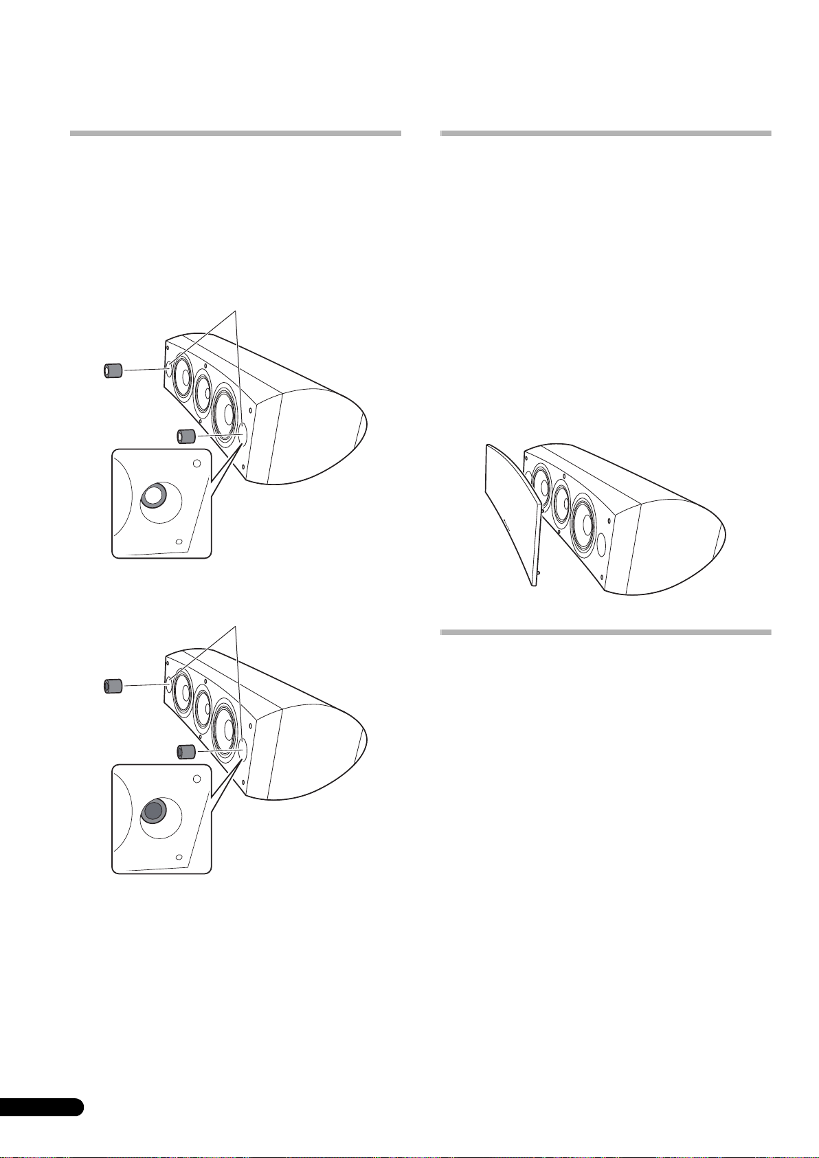
Övrig information
Användning av
skumgummipropparna
Skumgummiproppar medföljer denna enhet för justering av
basljudet. Placera en skummgummipropp i basreflexportarna på
högtalarens vardera sida. Sätt in skumgummipropp A eller både
A och B propparna för att åstadkomma önskat ljud.
Användning av endast skummgummipropp A
Basreflexportar
Fastsättning/borttagning av
grillskydden
Dessa högtalare levereras med grillskydd som kan sättas fast och
tas bort på följande sätt:
1 Vid fastsättning av grillskyddet skall du passa in hålen på
högtalaren mot klackarna på grillen och trycka in ordentligt.
2 Vid borttagning av grillskyddet skall du fatta i den övre
och nedre kanten på grillskyddets vänstra sida med båda
händerna och dra varsamt mot dig för att separera den
vänstra sidan av grillskyddet från högtalaren.
3 Flytta därefter händerna till grillkåpans mitt och dra
grillens övre och nedre kanter varsamt igen mot dig för att
separera mittenpartiet.
4 Fatta slutligen i den övre och nedre kanten på
grillskyddets högra sida och dra varsamt mot dig för att
separera den återstående delen av grillskyddet från
högtalaren.
Användning av både skumgummipropp A och B
Basreflexportar
Rengöring av högtalarhöljet
Vid normal användning bör det räcka med att torka av med en torr
duk för att hålla höljet rent. Om så erfordras, kan du rengöra med
en duk som har doppats i ett neutralt rengöringsmedel som har
spätts ut fem eller sex gånger med vatten och vridits ur ordentligt.
Använd inte möbelvax eller kraftiga rengöringsmedel.
Använd aldrig thinner, bensen, insektssprayer eller andra
kemikalier på eller nära högtalaren, därför att sådana kommer att
korrodera ytorna.
10
Sw
Page 83

Specifikationer
Hölje. . . . . . . . . . . . . . . . . . . . . . . . . . . . . . . . . . . .Golvtyp med basreflex
(magnetiskt avskärmad)
Utformning . . . . . . . . . . . . . . . . . . . . . . . . . . . . . . . . . . . . . . . . . . ..3-vägs
Woofer-element. . . . . . . . . . . . . . . . . . . . . . . . . . . . . . . . . .16 cm kon x 2
Mellanregister/diskantelement . . . . . . . . . . . . . 14 cm kon/3 cm dome
Impedans . . . . . . . . . . . . . . . . . . . . . . . . . . . . . . . . . . . . . . . . . . . . . . 6 Ω
Frekvensomfång . . . . . . . . . . . . . . . . . . . . . . . . . . . . . . 34 Hz till 100 kHz
Känslighet . . . . . . . . . . . . . . . . . . . . . . . . . . . . . . . . . . . . 88,5 dB (2,83 V)
Maximal ineffekt . . . . . . . . . . . . . . . . . . . . . . . . . . . . . . . . . . . . . . . 160 W
Yttermått . . . . . . . . . . . . . . . . .723 (B) mm x 263 (H) mm x 387 (D) mm
Vikt . . . . . . . . . . . . . . . . . . . . . . . . . . . . . . . . . . . . . . . . . . . . . . . . . . . 28 kg
Anmärkning
Tekniska data och utförande kan, i förbättringssyfte, ändras utan
föregående meddelande.
Magnetisk avskärmning
Denna högtalare är magnetiskt avskärmad. Beroende på
placeringen av högtalaren kan dock färgstörningar uppträda, om
högtalaren placeras mycket nära en TV-mottagares bildruta.
Om detta inträffar skall du stänga av TV-mottagaren och sätta på
den igen efter 15 minuter till 30 minuter. Om problemet kvarstår,
skall du placera högtalaren längre bort från TV-mottagaren.
Svenska
Medföljande tillbehör
Spetsar. . . . . . . . . . . . . . . . . . . . . . . . . . . . . . . . . . . . . . . . . . . . . . . . . . . 3
Korkdynor . . . . . . . . . . . . . . . . . . . . . . . . . . . . . . . . . . . . . . . . . . . . . . . . 3
Stora glidskyddsdynor . . . . . . . . . . . . . . . . . . . . . . . . . . . . . . . . . . . . . . 2
Små glidskyddsdynor . . . . . . . . . . . . . . . . . . . . . . . . . . . . . . . . . . . . . . . 4
Skumgummiproppar (A, B) . . . . . . . . . . . . . . . . . . . . . . . . . . . . . . . . . . 2
Högtalarstöd . . . . . . . . . . . . . . . . . . . . . . . . . . . . . . . . . . . . . . . . . . . . . . 1
Brickor . . . . . . . . . . . . . . . . . . . . . . . . . . . . . . . . . . . . . . . . . . . . . . . . . . . 2
Fjäderbricka. . . . . . . . . . . . . . . . . . . . . . . . . . . . . . . . . . . . . . . . . . . . . . . 1
Skruv (M5 x L40) . . . . . . . . . . . . . . . . . . . . . . . . . . . . . . . . . . . . . . . . . . . 1
Skruvar (M6 x L35) . . . . . . . . . . . . . . . . . . . . . . . . . . . . . . . . . . . . . . . . . 6
Glidskyddsdynor . . . . . . . . . . . . . . . . . . . . . . . . . . . . . . . . . . . . . . . . . . . 1
Bruksanvisning
är ett varumärke som finns på en produkt med Pioneers
Phase Control-teknologi. Denna teknologi möjliggör högklassig
ljudåtergivning från varje komponent genom en förbättrad total
fasanpassning.
Utgiven av Pioneer Corporation.
Copyright © 2008 Pioneer Corporation.
Kopiering förbjuden.
11
Sw
Page 84

Tak for købet af dette produkt fra Pioneer.
Gennemlæs venligst denne brugsanvisning grundigt, så du ved, hvordan du skal anvende din model på korrekt vis.
Gem brugsvejledningen på et sikkert sted, når du er færdig med at læse den, så du senere kan konsultere den.
Indhold
Inden du begynder
Kassen indeholder
Om EX-serien
Teknologien bag S-8EX . . . . . . . . . . . . . . . . . . . . . . . . . . . . . . . . . . 3
CST. . . . . . . . . . . . . . . . . . . . . . . . . . . . . . . . . . . . . . . . . . . . . . . . 3
Membraner af keramisk grafit . . . . . . . . . . . . . . . . . . . . . . . . . . . 3
Membran af magnesium-legering . . . . . . . . . . . . . . . . . . . . . . . . 4
Basdriver . . . . . . . . . . . . . . . . . . . . . . . . . . . . . . . . . . . . . . . . . . . 4
Baskabinetkonstruktion . . . . . . . . . . . . . . . . . . . . . . . . . . . . . . . . 4
Delefiltre. . . . . . . . . . . . . . . . . . . . . . . . . . . . . . . . . . . . . . . . . . . . 4
Samarbejde med Air Studios . . . . . . . . . . . . . . . . . . . . . . . . . . . . 4
Installation og placering
Installationsanvisninger . . . . . . . . . . . . . . . . . . . . . . . . . . . . . . . . . 5
Hvis højttaleren installeres direkte på gulvet. . . . . . . . . . . . . . . . . 5
Anvendelse af den medfølgende højttalerfod . . . . . . . . . . . . . . . . 5
Anvendelse af Pioneer højttalerstativ CP-7EX . . . . . . . . . . . . . . . 6
Valg af installationssted for højttalersystemet. . . . . . . . . . . . . . . . 6
Connections
Tilslutning til en forstærker . . . . . . . . . . . . . . . . . . . . . . . . . . . . . . . 7
Tilslutning af kablerne. . . . . . . . . . . . . . . . . . . . . . . . . . . . . . . . . . . 7
Etkabels tilslutning . . . . . . . . . . . . . . . . . . . . . . . . . . . . . . . . . . . . 8
Tokabels-tilslutning. . . . . . . . . . . . . . . . . . . . . . . . . . . . . . . . . . . . 8
Tilslutning af en højttaler til to forstærkere (Biamping) . . . . . . . . . 9
Anden information
Anvendelse af skumplastpropperne . . . . . . . . . . . . . . . . . . . . . . . 10
Anvendelse af kun skumplastprop A. . . . . . . . . . . . . . . . . . . . . . 10
Anvendelse af både skumplastprop A og B. . . . . . . . . . . . . . . . . 10
Påsætning/aftagning af gitterdæksel . . . . . . . . . . . . . . . . . . . . . . 10
Rengøring af højttalerkabinettet . . . . . . . . . . . . . . . . . . . . . . . . . . 10
Tekniske specifikationer . . . . . . . . . . . . . . . . . . . . . . . . . . . . . . . . 11
Inden du begynder
• Dette højttalersystems nominelle impedans er 6 Ω. Slut
højttalersystemet til en forstærker med en
belastningsimpedans fra 6 Ω til 16 Ω (en model med “6 Ω –
16 Ω” vist på højttalerudgangsterminalerne).
Iagttag venligst de følgende sikkerhedsforskrifter, således at
skade på højttalersystemet på grund af
indgangsoverbelastning undgås:
• Strømforsyningen til højttalersystemet må ikke overstige den
højeste tilladte indgang.
• Anvend ikke en for kraftig forstærkerlydstyrke, når du
anvender en grafisk equalizer til at fremhæve kraftig lyd i det
højfrekvente område.
• Tving ikke en forstærker med svag strømforsyning til at
producere en kraftig lyd (forstærkerens harmoniske
forvrængning vil blive øget, hvorved højttaleren kan lide
skade).
Forsigtig: installation
• Når du installerer denne enhed, skal du sørge for, at den er
ordentligt fastgjort, og du bør undgå steder, hvor den kan falde
ned og være årsag til tilskadekomst i tilfælde af en
naturkatastrofe (som for eksempel et jordskælv).
• Monter ikke disse højttalere på væggen eller loftet. De kan
falde ned og være årsag til tilskadekomst.
• Monter ikke højttalerne i højden i loftet eller på væggen. Hvis
de monteres forkert, kan højttalergitteret falde ned og være
årsag til materiel skade og personskade.
• Sluk for og tag dit AV-udstyr ud af forbindelse og gå frem efter
anvisningerne, når du tilslutter apparaterne. Sørg for at
anvende de rigtige tilslutningskabler.
Forsigtig: ibrug
• Anbring ikke højttaleren på en ustabil flade. Den kan i så fald
udgøre en fare, hvis den vælter, og desuden øve skade på
udstyret.
• Anvend ikke højttaleren til at frembringe forvrænget lyd i et
længere tidsrum. Dette kan resultere i fare for brand.
• Lad være med at sidde eller stå på højttaleren og lad ikke børn
lege på højttaleren.
• Anbring ikke store og tunge genstande oven på højttaleren.
• Anbring ikke magnetiske genstande, som for eksempel en
skruetrækker eller jerndele i nærheden af diskant- eller
mellemtonehøjttaleren. Eftersom højttalerne betjener sig af
kraftige magneter, kan genstandene blive tiltrukket, med
personskade eller skade på membranen som resultat.
2
Da
EU’s
K058_Da
Page 85

Kassen indeholder
A
B
Pigge x 3
Korkplader x 3
Store skridsikre puder x 2
Små skridsikre puder x 4
Om EX-serien
EX-serien, som indeholder masser af teknologisk know-how
bag TAD højttalerserien, Pioneers flagskib, er udviklet med
det mål at skabe en så ultimativ højttaler, som det er muligt
i dens prisklasse.
De sig n og prod ukt ion a f EX -se rien er e t in tern ati ona lt pr oje kt, som
repræsenterer det bedste i Pioneers højttalerteknologi.
Teknologien bag S-8EX
CST
Kernedriveren i dette system er Coherent Source Transducer
(CTS), som trækker på den teknologi, der anvendes i TAD.
Diskanthøjttalerens membran er monteret koncentrisk inden for
spidsen af mellemtonekeglen og giver et spidspunkt for lyden fra
400 Hz til 100 kHz. CST sikrer en perfekt, spektral balance mellem
den direkte og den reflekterede lyd, som når den lyttende persons
øre, hvorved der frembringes en mere konsistent lyd i hele
lytterummet samt forbedret lydbilledkapacitet.
Dansk
Skumplastpropper (A,B) x 2
Højttalerfod x 1
Skiver x 2
Fjederskive x 1
Skrue (M5 x L40) x 1
Skrue (M6 x L35) x 6
Gitter x 1
Brugsanvisning
Membraner af keramisk grafit
CST’s diskanthøjttaler er udstyret med en membran af keramisk
grafit, som yder topniveau-styrke og dæmpningskarakteristik, som
er praktisk taget uden konkurrence fra nogen andre materialer,
som for tiden anvendes i højkvalitets audio-højttalersystemer. Den
keramiske grafits lethed og usædvanlige styrke går sammen om
at skabe højttalere, hvis membranresonans kan række langt ud
over deres hørbare område.
Hastighed (m/s)
18 000
16 000
14 000
12 000
10 000
8 000
6 000
Keramisk grafit
Aluminium
Beryllium
Bor-legering
Keramisk kulstof
Papir
Titanium
4 000
2 000
0
0,005 0,015 0,025
Indre tab
3
Da
Page 86

Membran af magnesium-legering
CST’s mellemtone-egenskaber består af en membran af
magnesium-legering, hvis karakteristiske lethed og høje indre tab
skaber fortrinlig transiens og minimal farvning af
mellemtonelyden.
Basdriver
Basdriveren på nedenstående billede tjener som fundamentet for
S-8EX-højttalersystemet. Driverens styrke er et resultat af Aramid/
Carbon kompositmateriale, som oprindeligt skabtes under
udviklingen af S-1EX, som anvendes i dens membran. Pioneers
eksklusive LDMC magnetiske kredsteknologi er anvendt for at
bevare lineariteten fra lave til høje udgangsniveauer og for at gøre
forvrængning mindst mulig.
Baskabinetkonstruktion
S-8EX’s unikke form er baseret på logisk nødvendighed. For at
synkronisere ankomsttiden for lyden fra CTS og de to basdrivere,
er hver driver monteret på en resonansskærm, hvis formål er at
skabe en yderst følsom kurve, som er kendt som
“præcisionskurven” (se nedenstående illustration).
Resonansskærmen er fremstillet af en op til 65 mm tyk MDF
(Medium Density Fiberboard), som ydermere har styrken til at
tilbageholde drivernes drivkraft. Derudover er basporten skåret ud
af en ekstremt tyk blok af MDF, hvorved vindstøj reduceres, og en
klar, dyb bas opnås.
Delefiltre
Delefiltrene betjener sig udelukkende af de fineste dele. Luftkernespoler, ikke-ledende resistorer, og filmkondensatorer i signalvejen
er alle omhyggeligt udvalgt og optimeret, så CST-driveren kan give
den størst mulige transparens til signalet. Basdriverne betjener
sig af silicium-stålplade-kerneledere, som minimerer
forvrængning og tab under energioverførsel. Alle komponenter er
sluttet direkte til deres respektive tilslutningsmaterialer, i stedet
for en printplade, hvilket giver minimalt tab og maksimal ydelse.
Samarbejde med Air Studios
Siden dets grundlæggelse af George Martin i 1969 i London, har
Englands Air Studios opnået enestående respekt fra masser af
kunstnere, som anerkender det som verdens førende pladestudie.
Air Studios-seglet, som tildeltes S-8EX, angiver at disse højttalere
er i stand til at frembringe den højkvalitetslyd, som kræves af
verdens bedste lydskabere.
4
Da
Præcisionskurve
Page 87

Installation og placering
Vigtigt
Installationsanvisninger
Vælg en ønsket installationsopsætning fra det følgende.
Hvis højttaleren installeres direkte på gulvet
Anvend de medfølgende pigge, hvis du installerer højttaleren
direkte på gulvet.
Montering
1 Drej piggene ind i de gevindskårne metalindsatser (M6),
som er indlejret i højttalerens underside, og stram godt til.
Pig
Anvendelse af den medfølgende højttalerfod
Hvis du anvender den medfølgende højttalerfod. er det ikke
nødvendigt at anvende de medfølgende pigge.
Montering
1 Fastgør de medfølgende skridsikre plader (små) på de fire
steder på undersiden af foden.
Små skridsikre puder
Dansk
2 Fastgør de medfølgende skridsikre plader (store) på de to
steder på oversiden af højttalerfoden.
Store skridsikre puder
Højttalers
underside
2 Sæt korkpladerne i de stillinger, hvor piggenes spidser vil
ramme, når højttaleren sættes ned.
3 Anbring højttaleren oven på korkpladerne.
Hvis du ikke anvender korkpladerne, når højttalerne
anbringes, kan piggene øve skade på gulvet. Hvis du
agter at anvende piggene, anbefaler vi stærkt
anvendelse af korkpladerne.
• Da denne højttaler vejer omkring 28 kg, er det meget farligt at
forsøge at indstille pigmøtrikken, mens højttaleren hælder.
Sørg for at anbringe højttaleren på et blødt underlag (som for
eksempel et tæppe), således at den ikke øver skade på gulvet,
og sørg derefter for, at installationen udføres af mindst to
personer.
3 Anbring højttaleren oven på foden.
Anvendelse af den medfølgende højttalerfod muliggør
finjustering af højttalervinklen.
Højttalerfod
Vigtigt
• Når den medfølgende højttalerfod anvendes, må højttalerne
ikke fastgøres med skruer. Højttaleren kan falde ned og
forårsage personskade.
5
Da
Page 88

Anvendelse af Pioneer højttalerstativ CP-7EX
For at anvende CP-7EX stativet, skal den medfølgende højttalerfod
først sættes på stativstængerne på CP-7EX. Saml stativerne som
vist herunder.
Montering
1 Fjern emballagen fra de undersænkskruehullerne i
højttalerfoden.
Valg af installationssted for højttalersystemet
Placering i lytterummet vil have en stor virkning på den totale
ydelse af S-8EX-højttalersystemet i henseende til basydelse, tonal
nøjagtighed og lydbilleddannelse. Alle rum er forskellige, så dette
afsnit er kun tænkt som en rettesnor. Hvis du eksperimenterer
med dette i dit rum, vil du opnå optimale resultater.
Anvend illustrationen herunder som en rettesnor til at finde frem
til den optimale højttalerplacering.
30 cm til 60 cm
2 Monter højttalerfoden på stativstængerne på CP-7EX.
Anvend kun de medfølgende skruer (M6 x L35).
Skruer (M6 x L35)
Højttalerfod
Stativstænger
Stativsokkel
CP-7EX
3 Fastgør de skridsikre puder (store).
4 Anvendelse af de medfølgende skruer (M5 x L40),
fjederskiven og skiven til at fastgøre højttaleren til stativet.
For at bidrage til at højttaleren ikke falder ned, må du kun
benytte de medfølgende skruer til at fastgøre
højttalersystemet til højttalerstativet. Se de instruktioner, som
følger med CP-7EX højttalerstativet, angående detaljer.
Fronthøjttaler
Centerhøjttaler
Lytteposition
.
Fronthøjttaler
Vigtigt
• Anbring ikke højttaleren på et sted, hvor den vil blive udsat for
direkte sol, og undgå at anbringe den i nærheden af
varmeapparater og klima-anlæg. Dette kan føre til skævhed i
og misfarvning af højttalerkabinettet og øve skade på
højttaleren.
• Pioneer påtager sig intet ansvar for skader, som er et resultat
af samling, fejlagtig montering, utilstrækkelig forstærkning,
misbrug af produktet, naturrelaterede påvirkninger og
lignende.
6
Da
Store skridsikre puder
Skiver
Fjederskive
skrue (M5 x L40)
Page 89

Connections
Tilslutning til en forstærker
Denne højttaler inkluderer ikke højttalerkabler, som anvendes til
tilslutning af en forstærker. Tag de følgende faktorer i betragtning,
når du vælger højttalerkabler, således at du kan få det mest
mulige ud af dit højttalersystem:
• Anvend om muligt kraftige højttalerkabler og begræns
kablerne til den mindst mulige længde.
• Kabler har forskellige egenskaber. Hav dette in mente, når du
anvender kabler.
• Vælg kabler med en så lille modstand som muligt, og bekræft,
at kablerne til højttalerterminalerne og forstærkeren er sat helt
og ordentligt ind.
ADVARSEL
Disse højtalerterminaler leder FARLIG
STRØMFØRENDE spænding. For at forhindre risikoen
for elektrisk stød, når højtalerkablerne tilsluttes eller
kobles fra, trækkes strømkablet ud af stikdåsen, før der
røres ved uisolerede dele.
D3-4-2-2-3_A_Da
Tilslutning af kablerne
1 Sluk for forstærkeren.
2 Sæt højttalerkablerne i indgangsterminalerne (nederst)
på bagsiden af højttaleren. Med hensyn til
indgangsterminalernes polaritet er rød positiv (+) og sort
negativ (–).
3 Sæt den anden ende af kablerne i udgangsterminalerne
på forstærkeren (vi henviser til brugsanvisningen for din
forstærker angående yderligere detaljer).
Stik til kortslutningsstift
Rød terminal (+)
Sort terminal
(–)
• Tag fat i hætteknapperne på de nederste indgangsterminaler
og drej dem til venstre (retningen mod uret), sæt
højttalerkabeltrådene ind i hullerne på terminalklemmerne, og
stram derefter knapperne for at fastgøre kortslutningsstiften
såvel som trådene.
• Du kan også anvende bananstik til denne tilslutning. Hvis du
ønsker at gøre dette, skal du først tage hætterne af
indgangsterminalerne.
• Træk let i kablerne, når du har sat stikkene i, for at sikre dig, at
kabelenderne er sat ordentligt i terminalerne. Mangelfuld
tilslutning kan frembringe støj i og afbrydelser af lyden.
• Hvis kabeltrådene skulle falde ud af terminalerne, således at
der er risiko for at de kan komme i kontakt med hinanden, vil
forstærkeren blive udsat for en ekstra stor belastning. Dette
kan bevirke, at forstærkeren holder op med at fungere og kan
endog medføre skade på forstærkeren.
Dansk
Da
7
Page 90

Etkabels tilslutning
Ved tilslutninger med et enkelt kabel, skal du slutte mellem-til-højog lavfrekvensdelene i delefilteret til kortslutningsstiften, som
følger med denne enhed, og derefter slutte (+) kabeltråden fra din
forstærker til en af de røde tilslutningsklemmer og (–) kabeltråden
fra din forstærker til en af de sorte tilslutningsklemmer, som vist
på illustrationen herunder.
Tokabels-tilslutning
I en tokabels tilslutning tilslutter du uafhængigt de
højttalersystemer, som kører fra forstærkeren til deres respektive
høj- og lavfrekvente stik. Dette resulterer i, at CST-driveren og
basdriverne sluttes uafhængigt og direkte til forstærkeren,
hvorved du opnår frihed til at optimere kabeltypen for hver af
driverne. Slut et sæt kabeltråde til det nederste sæt
tilslutningsklemmer (basdriver-specifikt netværk). Slut derefter et
andet sæt ledninger til de øverste tilslutningsklemmer (CTSspecifikt netværk). Slut dernæst begge sæt kabeltråde til de
rigtige terminaler på din forstærker. Vær påpasselig med at slutte
begge (+) kabeltråde til (+) forstærkerterminalerne og begge (–)
kabeltråde til (–) forstærkerterminalerne som vist på illustrationen
herunder.
(Kun en kanal vises)
Forstærker (bag)
Højttaler
HF
HF
Tilslutning af
kortslutningsstift
LF
LF
Højttaler (bag): Indgangspanel
SPEAKERS OUTPUT
(Kun en kanal vises)
Forstærker (bag)
SPEAKERS OUTPUT
Højttaler
HF
LF
HF
LF
Højttaler (bag): Indgangspanel
8
Da
Page 91

Tilslutning af en højttaler til to forstærkere
Forsigtig
(Biamping)
Systemet med tilslutning af en højttaler til to forstærkere (biamping) muliggør den bedste ydelse, når der anvendes dedikerede forstærkere
for lav- og mellem-til-højfrekvenssektioner.
Der er to mulige konfigurationer, som normalt kaldes horisontal og vertikal biamping.
Fjern kortslutningsleddene, inden du slutter højttalerkablerne til bi-forstærkningstilslutningerne.
Forsømmelse af dette kan føre til beskadigelse af forstærkerne.
Vertikal biamping
Med denne konfiguration anvendes der identiske
stereoforstærkere for hvert højttalersystem. En kanal i hver
forstærker driver den lavfrekvente del, og den anden kanal driver
den højfrekvente del, som vist herunder.
Slut et sæt kabeltråde og forstærkerkanal til det nederste sæt
tilslutningsklemmer (basdriver-specifikt netværk).
Slut derefter et andet sæt kabeltråde og den anden
forstærkerkanal til de øverste tilslutningsklemmer (CTS-specifikt
netværk).
Vær påpasselig med slutte begge (+) kabeltråde til (+)
forstærkerterminalerne og begge (–) kabeltråde til (–)
forstærkerterminalerne.
Forforstærker (bag)
OUTPUT
(Kun en kanal vises)
OUTPUT
Y-adapter
(fås i handelen)
Effektforstærker
INPUT
(bag)
SPEAKERS OUTPUT
Ch.1 Ch.2
INPUT
Horisontal biamping
Med denne konfiguration kan du anvende forskellige
stereoforstærkere til lav- og mellem-til-høj-frekvens delene i
højttalersystemet (f.eks. rørforstærkere og høje frekvenser og solid
tilstand for lave frekvenser). Hver kanal i den ene forstærker driver
den lavfrekvente del af hvert højttalersystem, og hver kanal i den
anden forstærker driver mellem-til-høj-frekvensdelen som vist
herunder.
Denne metode kræver, at de to forstærkere har samme
forstærkning, da der ellers vil opstå en ubalance mellem lav- og
mellem-til-høj-frekvensgengivelsen fra højttalersystemet. Hvis du
er i tvivl om noget, bedes du rette henvendelse til din lokale
forhandler.
Forforstærker (bag)
OUTPUTOUTPUT
(Kun en kanal vises)
Effektforstærker
(bag) (høj frekvens)
SPEAKERS OUTPUT
Y-adapter (fås i handelen)
INPUT
Effektforstærker
(bag) (lav frekvens)
(Kun en kanal vises)(Kun en kanal vises)
INPUT
SPEAKERS OUTPUT
Dansk
HF
LF
Højttaler
HF
Højttaler (bag):
Indgangspanel
LF
Højttaler (bag):
Indgangspanel
HF
LF
Højttaler
HF
LF
9
Da
Page 92

Anden information
Anvendelse af skumplastpropperne
Denne enhed er forsynet med skumplastpropper, som er nyttige til
at regulere styrken af baslyden. Skumplastpropperne anvendes
ved at man forsigtigt anbringer dem i basrefleksportene på hver
side af højttaleren. Sæt enten kun skumplastprop A ind eller både
skumplastprop A og B ind for at opnå den ønskede lyd.
Anvendelse af kun skumplastprop A
Basreflexporte
Påsætning/aftagning af gitterdæksel
Dette højttalersystem er udstyret med gitterdæksler. Disse kan
sættes på og tages af på følgende måde:
1 For at sætte gitterdækslet på, skal du sætte hullerne på
højttaleren ud for fordybningerne på gitteret og trykke fast
ind.
2 Gitterdækslet tages af ved at man tager fat i den øverste
og nederste kant på gitterdækslet i venstre side og forsigtigt
trækker det mod dig for at adskille den venstre del af
gitterdækslet fra højttaleren.
3 Anbring derefter hænderne ved midten af gitterdækslet
og træk igen forsigtigt den øverste og nederste kant mod dig
for at adskille den mellemste del.
4 Tag til sidst fat i den øverste og nederste kant på
gitterdækslet i højre side og træk den forsigtigt mod dig for
at adskille den tilbageværende del af gitterdækslet fra
højttaleren.
Anvendelse af både skumplastprop A og B
Basreflexporte
Rengøring af højttalerkabinettet
Ved normal brug bør aftørring med en tør klud være tilstrækkeligt
til at holde kabinettet rent. Om nødvendigt rengøres med en klud,
som er dyppet i et neutralt rengøringsmiddel, som er fortyndet fem
eller seks gange med vand og derefter vredet godt op. Anvend ikke
møbelpolitur eller rensemidler.
Anvend aldrig fortynder, rensebenzin, insektspray eller andre
kemikalier på eller i nærheden af denne enhed, da disse midler vil
ødelægge overfladerne.
10
Da
Page 93

Tekniske specifikationer
Kabinet. . . . . . . . . . . . . . . . . . Basrefleks, type til anbringelse på gulvet
(magnetisk afskærmet)
Konfiguration . . . . . . . . . . . . . . . . . . . . . . . . . . . . . . . . . . . . . . . . . .3-vejs
Bashøjttaler. . . . . . . . . . . . . . . . . . . . . . . . . . . 16 cm keglemembran x 2
Mellemtone-diskanthøjttaler . . . . . .14 cm keglemembran/3 cm dome
Impedans . . . . . . . . . . . . . . . . . . . . . . . . . . . . . . . . . . . . . . . . . . . . . . 6 Ω
Frekvensgang . . . . . . . . . . . . . . . . . . . . . . . . . . . . . . . . 34 Hz til 100 kHz
Følsomhed. . . . . . . . . . . . . . . . . . . . . . . . . . . . . . . . . . . . 88,5 dB (2,83 V)
Maks. indgangseffekt . . . . . . . . . . . . . . . . . . . . . . . . . . . . . . . . . . . 160 W
Udvendige mål . . . . . . . . . . . . 723 (B) mm x 263 (H) mm x 387 (D) mm
Vægt. . . . . . . . . . . . . . . . . . . . . . . . . . . . . . . . . . . . . . . . . . . . . . . . . . 28 kg
Medfølgende tilbehør
Pigge . . . . . . . . . . . . . . . . . . . . . . . . . . . . . . . . . . . . . . . . . . . . . . . . . . . . 3
Korkplader . . . . . . . . . . . . . . . . . . . . . . . . . . . . . . . . . . . . . . . . . . . . . . . . 3
Store skridsikre puder . . . . . . . . . . . . . . . . . . . . . . . . . . . . . . . . . . . . . . 2
Små skridsikre puder . . . . . . . . . . . . . . . . . . . . . . . . . . . . . . . . . . . . . . . 4
Skumplastpropper (A,B). . . . . . . . . . . . . . . . . . . . . . . . . . . . . . . . . . . . . 2
Højttalerfod . . . . . . . . . . . . . . . . . . . . . . . . . . . . . . . . . . . . . . . . . . . . . . . 1
Skiver . . . . . . . . . . . . . . . . . . . . . . . . . . . . . . . . . . . . . . . . . . . . . . . . . . . . 2
Fjederskive. . . . . . . . . . . . . . . . . . . . . . . . . . . . . . . . . . . . . . . . . . . . . . . . 1
Skrue (M5 x L40) . . . . . . . . . . . . . . . . . . . . . . . . . . . . . . . . . . . . . . . . . . . 1
Skruer (M6 x L35) . . . . . . . . . . . . . . . . . . . . . . . . . . . . . . . . . . . . . . . . . . 6
Gitter . . . . . . . . . . . . . . . . . . . . . . . . . . . . . . . . . . . . . . . . . . . . . . . . . . . . 1
Brugsanvisning
Bemærk
Tekniske specifikationer og design kan ændres uden varsel på
grund af forbedringer.
Magnetisk afskærmning
Dette højttalersystem er magnetisk afskærmet. Afhængigt af
installationsstedet, kan der imidlertid opstå farveforvrængning,
hvis højttalersystemet stilles meget tæt på skærmen på et
fjernsyn.
Hvis dette sker, skal du slukke for fjernsynet, og derefter tænde for
det igen efter 15 minutters til 30 minutters forløb. Hvis problemet
vedvarer, skal du flytte højttalersystemet længere væk fra
fjernsynet.
Dansk
er et varemærke for et produkt med Pioneers fasekontrolteknologi. Denne teknologi muliggør højkvalitets lydgengivelse via
hver enkelt komponent ved forbedring af den generelle
faseoverensstemmelse.
Published by Pioneer Corporation.
Copyright © 2008 Pioneer Corporation.
Alle rettigheder forbeholdes.
11
Da
Page 94

Vi takker for innkjøpet av dette Pioneer-produktet.
Vennligst les igjennom denne brukerveiledningen slik at du blir godt fortrolig med riktig betjening av denne modellen.
Etter å ha nøye gjennomlest brukerveiledningen bør den oppbevares på et trygt sted for fremtidig konsultasjon.
Innhold
Før du går i gang
Eskens innhold
Informasjon om EX-serien
Teknologien som ligger bak S-8EX. . . . . . . . . . . . . . . . . . . . . . . . . . 3
CST. . . . . . . . . . . . . . . . . . . . . . . . . . . . . . . . . . . . . . . . . . . . . . . . 3
Membran av keramisk grafitt . . . . . . . . . . . . . . . . . . . . . . . . . . . . 3
Membraner av legert magnesium. . . . . . . . . . . . . . . . . . . . . . . . . 4
Basselementet . . . . . . . . . . . . . . . . . . . . . . . . . . . . . . . . . . . . . . . 4
Basselementenes kammerkonstruksjon. . . . . . . . . . . . . . . . . . . . 4
Delefilter. . . . . . . . . . . . . . . . . . . . . . . . . . . . . . . . . . . . . . . . . . . . 4
Samarbeid med Air Studios . . . . . . . . . . . . . . . . . . . . . . . . . . . . . 4
Installasjon og plassering
Installering . . . . . . . . . . . . . . . . . . . . . . . . . . . . . . . . . . . . . . . . . . . 5
Ved installering direkte på gulvet . . . . . . . . . . . . . . . . . . . . . . . . . 5
Bruk av den medfølgende høyttalerfoten . . . . . . . . . . . . . . . . . . . 5
Bruk av høyttalerstativet Pioneer CP-7EX . . . . . . . . . . . . . . . . . . . 6
Valg av høyttalersystemets plassering . . . . . . . . . . . . . . . . . . . . . 6
Tilkoblinger
Kobling til en forsterker. . . . . . . . . . . . . . . . . . . . . . . . . . . . . . . . . . 7
Tilkobling av kablene . . . . . . . . . . . . . . . . . . . . . . . . . . . . . . . . . . . . 7
Tilkoblinger med enkel-wiring . . . . . . . . . . . . . . . . . . . . . . . . . . . . 8
Bi-Wiring . . . . . . . . . . . . . . . . . . . . . . . . . . . . . . . . . . . . . . . . . . . 8
Bi-forsterkningstilkoblinger (Bi-amping) . . . . . . . . . . . . . . . . . . . 9
Annen informasjon
Bruk av skumplugger . . . . . . . . . . . . . . . . . . . . . . . . . . . . . . . . . . 10
Bruk av kun A-pluggen . . . . . . . . . . . . . . . . . . . . . . . . . . . . . . . . 10
Bruk av både A- og B-pluggen . . . . . . . . . . . . . . . . . . . . . . . . . . 10
Montering/fjerning av grillen. . . . . . . . . . . . . . . . . . . . . . . . . . . . . 10
Rengjøring av høyttalerkabinettet . . . . . . . . . . . . . . . . . . . . . . . . . 10
Spesifikasjoner . . . . . . . . . . . . . . . . . . . . . . . . . . . . . . . . . . . . . . . 11
Før du går i gang
• Den nominelle impedansen for høyttalersystemet er 6 Ω.
Koble høyttalersystemet til en forsterker som har en
belastningsimpedanse på mellom 6 Ω og 16 Ω (modeller med
“6 Ω – 16 Ω” avmerket på forsterkerens utgangsterminaler).
For å unngå skade på høyttalerne pga. overbelastning bør du
vennligst iaktta følgende forholdsregler:
• Ikke belast høyttalersystemet i overkant av det som er
spesifisert som maksimal ytelse.
• Ved bruk av en grafisk equalizer for å forsterke lydbildet i
høyfrekvensområdet må det ikke benyttes et overdrevent høyt
volumnivå med forsterkeren.
• Forsøk aldri å trekke høye volumnivåer fra en forsterker med
lav yteevne (forsterkerens harmoniske forvrengning vil øke og
kan dermed påføre skade på høyttaleren).
Forsiktig: Installasjon
• Ved plassering av høyttalerne må du påse at de er forsvarlig
sikret og unngå steder hvor de kan velte eller påføre
personskader i tilfelle det oppstår en naturkatastrofe (som
f.eks. jordskjelv).
• Ikke fest disse høyttalerne til vegger eller tak. De kan falle ned
og dermed påføre personskader.
• Ikke monter høyttalerne høyt opp i et tak eller på en vegg. Hvis
de festes uforsvarlig kan de falle ned og dermed påføre skade
på person eller utstyr.
• Slå av og frakoble alt stereoutstyr og følg brukerveiledningene
når komponenter skal tilkobles. Pass på å bruke egnede kabler
for tilkoblingene.
Forsiktig: Ved bruk
• Ikke plasser høyttalerne på ustabile flater. Risiko for
personskade oppstår hvis de velter, så vel som at utstyret kan
skades.
• Ikke benytt høyttalerne til avspilling av forvrengte lyder i lengre
tid. Dette medfører risiko for brann.
• Ikke sitt eller stå på høyttalerne eller la barn leke oppå
høyttalerne.
• Ikke plasser store eller tunge gjenstander oppå høyttalerne.
• Ikke legg magnetiske gjenstander som f.eks. skrutrekkere eller
deler som inneholder jern i nærheten av tweeter- eller
mellomtoneelementene. Høyttalerelementene benytter
kraftige magneter, slik at gjenstander kan tiltrekkes og
dermed forårsake personskader eller skade på membranene.
2
No
pluss
K058_No
Page 95

Eskens innhold
A
B
Spike x 3
Informasjon om EX-serien
EX-serien fra Pioneer er rikelig utstyrt med teknologisk
knowhow hentet fra TAD-høyttalerne som er Pioneers
flaggskip. EX-serien har blitt utviklet med det formål å skape
den ultimate høyttaler innenfor sitt prisområde.
EX-seriens utforming og produksjon representerer det ytterste i
Pioneers høyttalerteknologi som har blitt frembragt gjennom et
større internasjonalt samarbeid.
Korkskive x 3
Store anti-glifelt x 2
Lite anti-glifelt x 4
Skumplugg (A, B) x 2
Teknologien som ligger bak S-8EX
CST
Kjernen i høyttalersystemet er den såkalte Coherent Source
Transducer (CST), som henter sin teknologi fra TAD. Tweeterens
membran er montert konsentrisk i mellomtonenes øverste del slik
at et lydkildepunkt oppstår for frekvensene 400 Hz til 100 kHz. CST
garanterer at det forekommer en perfekt spektral balanse mellom
de direkte og reflekterte lydene som mottas av lytterens ører, og gir
et mer konsistent lydbilde gjennom hele rommet og forbedrer
uttrykksevnen.
Norsk
Membran av keramisk grafitt
CSTs tweeter er utstyrt med en membran av keramisk grafitt som
gir styrke på toppnivå og dempeegenskaper som praktisk talt
overgår et hvilket som helst annet materiale som for tiden blir
brukt i high-end audio høyttalersystemer. Kombinasjonen av det
keramiske grafittmaterialets letthet og eksepsjonelle styrke har
ført til utviklingen av høyttalere med en membranresonans som
strekker seg langt utenfor hørbare frekvenser.
Hastighet (m/s)
Høyttalerfot x 1
Pakning x 2
Fjærskive x 1
Skrue (M5 x L40) x 1
Skrue (M6 x L35) x 6
Grill x 1
Bruksanvisning
18 000
16 000
14 000
12 000
10 000
8 000
6 000
4 000
2 000
Keramisk grafitt
Aluminium
Beryllium
Boronlegering
Keramisk karbon
Papir
Titanium
0
0,005 0,015
0,025
Indre tap
3
No
Page 96

Membraner av legert magnesium
CSTs mellomtone er utstyrt med en membran av legert
magnesium hvis letthet og høye indre tap (god demping)
frembringer fremragende transientgjengivelse og minimal farging
av mellomtonen.
Basselementet
Elementet for bassen som er avbildet nedenfor tar hånd om den
fundamentale delen av høyttalersystemet S-8EX. Elementets
eksepsjonelle styrke har blitt oppnådd ved å bruke
komposittmaterialet karbonaramid som opprinnelig ble skapt ved
utviklingen av S-1EX for bruk i denne høyttalerens membraner.
Pioneers eksklusive magnetiske kretsteknologi kalt LDMC, har
blitt implementert for å ivareta linearitet hele veien fra lave til høye
utgangsnivåer og for å oppnå minst mulig forvrengning.
Basselementenes kammerkonstruksjon
Den unike utformingen av S-8EX oppstod av logisk nødvendige
årsaker. For å kunne synkronisere lydens mottakstid fra CST og de
to basselementene, har hvert element blitt montert oppå en baffel
som bidrar til utformingen av en høyst delikat kurve eller
”presisjonskurve” (se illustrasjonen nedenfor). Baffelen er laget av
65 mm tykt MDF (Medium Density Fiberboard), og er dermed sterk
nok til å motstå trykket som utgår fra høyttalerelementene. I tillegg
har bassporten blitt utskåret av en spesielt tykk blokk laget av
MDF, som reduserer vindstøy og bevirker en klar og dyp bass.
Delefilter
Delefilterne benytter kun komponenter av ypperste kvalitet.
Høyttalerens luftspoler, ikke-induserende resistorer og filmkondensatorer i signalgangen har blitt valgt med stor omhu og er
optimalisert for CST-elementet slik at signalet oppnår høyest
mulig transparens. Basselementene er utstyrt med
induktorkjerner laget av silikonstål som minimaliserer
forvrengning og tap ved energioverføringen. Samtlige
komponenter har blitt koplet direkte til deres respektive
koplingsstykker i stedet for å gå gjennom et kretskort. Dette
innebærer at signaltapet minimaliseres og maksimal ytelse
oppnås.
Samarbeid med Air Studios
Det engelske Air Studios ble etablert i London av George Martin i
1969 og har opparbeidet seg udelt respekt fra uttallige artister som
anerkjenner Air Studios som verdens ledende opptaksstudio.
Etiketten fra Air Studios som modell S-8EX har blitt tildelt, er en
pålitelig indikasjon på at høyttalerne er i stand til å produsere lyd
av aller høyeste kvalitet slik det kreves av verdens fremste
lydskapere.
4
No
Presisjonskurve
Page 97

Installasjon og plassering
Viktig
Installering
Velg en ønsket plassering blandt følgende anvisninger.
Ved installering direkte på gulvet
Bruk medfølgende spikes når du skal installere høyttalerne direkte
på en gulvflate.
Installasjon
1 Skru hver spike inn i hvert av de metallgjengede hullene
(M6) som er innfelt i høyttalerbunnen og stram de godt til.
Spike
Bruk av den medfølgende høyttalerfoten
Ved bruk av den medfølgende høyttalerfoten er det ikke nødvendig
å ta i bruk medfølgende spikes.
Installasjon
1 Fest medfølgende anti-glifelter (små) til de fire
avmerkede posisjonene på bunnen av høyttalerne.
Lite anti-glifelt
Høyttalerens
underside
2 Legg ut korkskivene på egnede steder slik at spikenes
spisser treffes når høyttaleren settes ned.
3 Legg høyttaleren oppå korkskivene.
Spikes kan påføre skade på gulvet hvis du unnlater å
bruke korkskivene ved plassering av høyttalerne. Hvis
du ønsker på bruke spikes anbefaler vi at du tar i bruk
korkskivene.
• Da hver enhet veier rundt 28 kg, er det svært risikofylt å justere
spikemutteren samtidig med at en vipper på en høyttaler. Pass
på å plassere enheten på et mykt underlag (som f.eks. et
pledd) slik at gulvet ikke tar skade og utfør monteringen med
minst to personer.
2 Fest medfølgende anti-glifelter (store) til de 2 avmerkede
punktene på høyttalerfotens toppflate.
re anti-glifelt
Sto
3 Legg høyttaleren oppå foten.
Bruk av den medfølgende høyttalerfoten muliggjør
fininnstilling av høyttalerens vinkel.
Høyttalerfot
Norsk
Viktig
• Ved bruk av den medfølgende høyttalerfoten skal høyttaleren
ikke skrus fast i en bestemt stilling. Høyttaleren kan velte og
forårsake personskader.
5
No
Page 98

Bruk av høyttalerstativet Pioneer CP-7EX
Ved bruk av høyttalerstativet CP-7EX må den medfølgende
høyttalerfoten festes til CP-7EXs stativsokler. Sett sammen stativet
som vist nedenfor.
Installasjon
1 Fjern beskytterhettene fra de innfelte skruehullene i
høyttalerfoten.
2 Fest høyttalerfoten til CP-7EXs stativsokler.
Bruk utelukkende de medfølgende skruene (M6 x L35).
Skruer (M6 x L35)
Valg av høyttalersystemets plassering
Valg av hvor høyttalersystemet S-8EX plasseres i et rom, kan ha
sterk innvirkning dets prestasjonsevne hva angår bassytelse, tonal
nøyaktighet og uttrykksevne. Ettersom alle rom er forskjellige bør
dette avsnittet kun anses som en veiledning. Eksperimentering i
det rommet du har til rådighet bør til syvende og sist gi det beste
resultat.
Bruk fremstillingen nedenfor som veileder for å oppnå optimal
plassering av høyttalerne.
30 cm til 60 cm
Fronthøyttaler
Midthøyttaler
Fronthøyttaler
Høyttalerfot
Stativsokler
Bunnplate
CP-7EX
3 Fest anti-glifeltene (store).
4 Bruk de medfølgende skruene (M5 x L40), fjærskiven og
pakningen til å feste høyttaleren til stativet.
For å forhindre at høyttalerne velter bør du kun benytte de
medfølgende skruene til å feste høyttalersystemet til
høyttalerstativet. Les brukerveiledningen som følger med
høyttalerstativet CP-7EX for flere detaljer.
Store anti-glifelt
Lytterens posisjon
.
Viktig
• Ikke plasser høyttalerne på steder hvor de kan utsettes for
direkte sollys og unngå plassering i nærheten av
varmeapparater eller klimaanlegg. Slike påkjenninger kan
forårsake at høyttalerkabinettet vrir seg, avfarges eller at
høyttalerelementene tar skade.
• Pioneer påtar seg ikke ansvar for skader som eventuelt
oppstår ved sammenstilling, feil montering, utilstrekkelige
forsterkninger, feil bruk av produktet, naturkatastrofer eller
lignende.
6
No
Pakning
Fjærskive
Skrue (M5xL40)
Page 99

Tilkoblinger
Kobling til en forsterker
Høyttalerkabler for tilkobling til en forsterker følger ikke med dette
høyttalersystemet. Ta følgende forhold i betraktning ved valget av
høyttalerkabler slik at du oppnår best mulig ytelse fra
høyttalersystemet:
• Benytt tykkest mulige høyttalerkabler og la kablene være av
kortest mulig lengde.
• Forskjellige kabler har ulike egenskaper. Dette bør overveies
ved valg av kabeltype.
• Velg kabler med minst mulig motstand og pass på at kablene
er koblet forsvarlig til høyttalerterminalene og forsterkeren.
ADVARSEL
Disse høyttalerkontaktene leder LIVSFARLIG strøm.
Dra ut strømledningen før du kobler til eller fra
høyttalerledningene og før du berører noen uisolerte
deler, dette for å unngå fare for elektrisk støt.
D3-4-2-2-3_A_No
Tilkobling av kablene
1 Skru av forsterkerens strøm.
2 Koble høyttalerkablene til inngangsterminalene (nedre)
på hver høyttalers bakside. Inngangsterminalenes polaritet:
rød er positiv (+) og sort er negativ (–).
3 Koble kabelens andre ender til forsterkerens
utgangsterminaler (se forsterkerens brukerveiledning for en
mer detaljert forklaring).
Slutningsbøyler
Rød terminal (+)
Sort terminal
(–)
Norsk
• Hold i de nedre terminalskruene og drei de mot venstre (mot
urviserne) og stikk kabeltrådene inn i hullene på
terminalstolpen. Stram deretter til terminalskruen slik at
sammenkoblingsbøylen så vel som kabeltrådene festes
forsvarlig.
• Du kan også bruke bananplugger for denne tilkoblingen.
Terminalkapslene må først fjernes fra inngangsterminalen når
du bruker av bananplugger.
• Etter at pluggene har blitt tilkoblet bør du dra lett i kablene for
å bekrefte at de er godt nok festet til terminalene. Dårlige
tilkoblinger er ofte årsak til støy og brudd på lyden.
• Dersom det skulle forekomme at kabeltrådene skyves ut av en
terminal kan de komme i kontakt med hverandre, noe som kan
føre til at forsterkeren overbelastes. Dette kan medføre at
forsterkeren slutter å fungere og til og med påføre skade på
forsterkeren.
No
7
Page 100

Tilkoblinger med enkel-wiring
SPEAKERS OUTPUT
Sammenkoblingsbøyle
Høyttaler (bakside): Inngangspanel
Forsterker
(bakpanel)
(Kun én kanal blir vist)
Høyttaler
HF
HF
LF
LF
Med enkel-wiring kobler du sammen områdene for mellomtone-tildiskant og lavfrekvensområdet på delefilteret med
sammenkoblingsbøylen som medfølger denne enheten. Koble
deretter (+)-ledningen fra forsterkeren til en av de røde
terminalstolpene og (–)-ledningen til en av de sorte
terminalstolpene som vist nedenfor.
Tilkoblinger med Bi-Wiring
Med bi-wiringstilkoblinger kobler du separate høy- og
lavfrekvensplugger fra forsterkerens til deres respektive terminaler
på høytalersystemet. Dette resulterer i at CST-elementet og
basselementet kobles direkte til forsterkeren uavhengig av
hverandre, noe som gir deg frihet til å velge optimale kabler for
hvert av elementene. Koble et sett kabler til den nedre rekken med
terminaler (spesifikt delefilter for basselementet). Koble deretter
andre sett med kabler til øvre terminaler (spesifikt delefilter for
CST). Koble deretter begge sett med kabler til respektive
terminaler på forsterkeren. Påse at begge (+)-ledninger kobles til
(+)-terminalene på forsterkeren og at begge (–)-ledninger kobles
til (–)-terminalene på forsterkeren som vist nedenfor.
(Kun én kanal blir vist)
Forsterker
(bakpanel)
SPEAKERS OUTPUT
Høyttaler
HF
LF
HF
LF
Høyttaler (bakside): Inngangspanel
8
No
 Loading...