

POWER AMPLIFIER M-IS22
AERO DUCT CONSTRUCTION
STANDBY/ON
STANDBY
P
H
O
N
E
S
STEREO POWER AMPLIFIER
M-IS22
THIS MANUAL IS APPLICABLE TO THE FOLLOWING MODEL(S) AND TYPE(S).
Type
MYXJ AC220-230V
NVXJ AC230V
Model
M-IS22
Power Requirement Remarks
ORDER NO.
RRV2445
This product is a component of a system.
For the accessories, instruction manuals etc., refer to the service manuals RRV2442 for
XC-IS22CD.
This product does not function properly when independent; to avoid malfunctions, be
sure to connect it to the prescribed system component(s), otherwise damage may
result.
Component System Service Manual Remarks
CD TUNER DECK XC-IS22CD RRV2442
STEREO POWER AMPLIFIER M-IS22 RRV2445 This Service Manual
SPEAKER SYSTEM
S-IS22 ––– RRV2450
––– S-IS22S RRV2451
CONTENTS
1. SAFETY INFORMATION
......................................
2. EXPLODED VIEWS AND PARTS LIST
3. SCHEMATIC DIAGRAM
4. PCB CONNECTION DIAGRAM
5. PCB PARTS LIST
6. ADJUSTMENT
....................................................
.......................................
..........................
...............................................
................
12
18
20
2
3
6
7. GENERAL INFORMATION
7.1 SINGLE OPERATION METHOD
8. PANEL FACILITIES AND SPECIFICATIONS
................................
.................
....
21
21
22
PIONEER CORPORATION 4-1, Meguro 1-chome, Meguro-ku, Tokyo 153-8654, Japan
PIONEER ELECTRONICS SERVICE, INC. P.O. Box 1760, Long Beach, CA 90801-1760, U.S.A.
PIONEER EUROPE NV Haven 1087, Keetberglaan 1, 9120 Melsele, Belgium
PIONEER ELECTRONICS ASIACENTRE PTE. LTD. 253 Alexandra Road, #04-01, Singapore 159936
PIONEER CORPORATION 2001
T – ZZK APR. 2001 Printed in Japan
M-IS22
1. SAFETY INFORMATION
This service manual is intended for qualified service technicians; it is not meant for the casual
do-it-yourselfer. Qualified technicians have the necessary test equipment and tools, and have been
trained to properly and safely repair complex products such as those covered by this manual.
Improperly performed repairs can adversely affect the safety and reliability of the product and may
void the warranty. If you are not qualified to perform the repair of this product properly and safely, you
should not risk trying to do so and refer the repair to a qualified service technician.
WARNING
This product contains lead in solder and certain electrical parts contain chemicals which are known to the state of California to
cause cancer, birth defects or other reproductive harm.
Health & Safety Code Section 25249.6 – Proposition 65
NOTICE
(FOR CANADIAN MODEL ONLY)
Fuse symbols (fast operating fuse) and/or (slow operating fuse) on PCB indicate that replacement
parts must be of identical designation.
REMARQUE
(POUR MODÈLE CANADIEN SEULEMENT)
Les symboles de fusible (fusible de type rapide) et/ou (fusible de type lent) sur CCI indiquent que
les pièces de remplacement doivent avoir la même désignation.
(FOR USA MODEL ONLY)
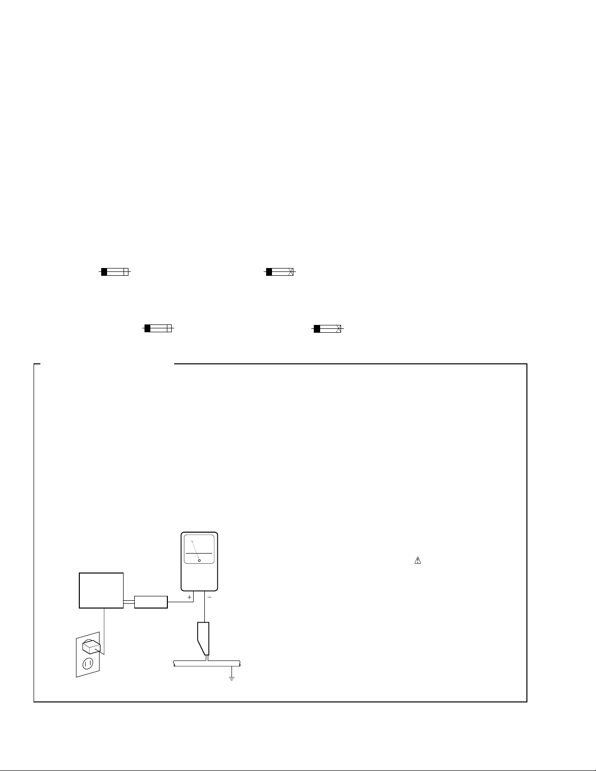
1. SAFETY PRECAUTIONS
The following check should be performed for the
continued protection of the customer and service
technician.
LEAKAGE CURRENT CHECK
Measure leakage current to a known earth ground
(water pipe, conduit, etc.) by connecting a leakage
current tester such as Simpson Model 229-2 or
equivalent between the earth ground and all exposed
metal parts of the appliance (input/output terminals,
screwheads, metal overlays, control shaft, etc.). Plug
the AC line cord of the appliance directly into a 120V
AC 60 Hz outlet and turn the AC power switch on. Any
current measured must not exceed 0.5 mA.
Reading should
not be above
0.5 mA
Earth
ground
Device
under
test
Also test with
plug reversed
(Using AC adapter
plug as required)
Test all
exposed metal
surfaces
AC Leakage Test
Leakage
current
tester
ANY MEASUREMENTS NOT WITHIN THE
LIMITS OUTLINED ABOVE ARE INDICATIVE
OF A POTENTIAL SHOCK HAZARD AND
MUST BE CORRECTED BEFORE RETURNING THE APPLIANCE TO THE CUSTOMER.
2. PRODUCT SAFETY NOTICE
Many electrical and mechanical parts in the appliance
have special safety related characteristics. These are
often not evident from visual inspection nor the
protection afforded by them necessarily can be obtained
by using replacement components rated for voltage,
wattage, etc. Replacement parts which have these
special safety characteristics are identified in this
Service Manual.
Electrical components having such features are
identified by marking with a
on the parts list in this Service Manual.
The use of a substitute replacement component which
does not have the same safety characteristics as the
PIONEER recommended replacement one, shown in the
parts list in this Service Manual, may create shock, fire,
or other hazards.
Product Safety is continuously under review and new
instructions are issued from time to time. For the latest
information, always consult the current PIONEER
Service Manual. A subscription to, or additional copies
of, PIONEER Service Manual may be obtained at a
nominal charge from PIONEER.
on the schematics and
2
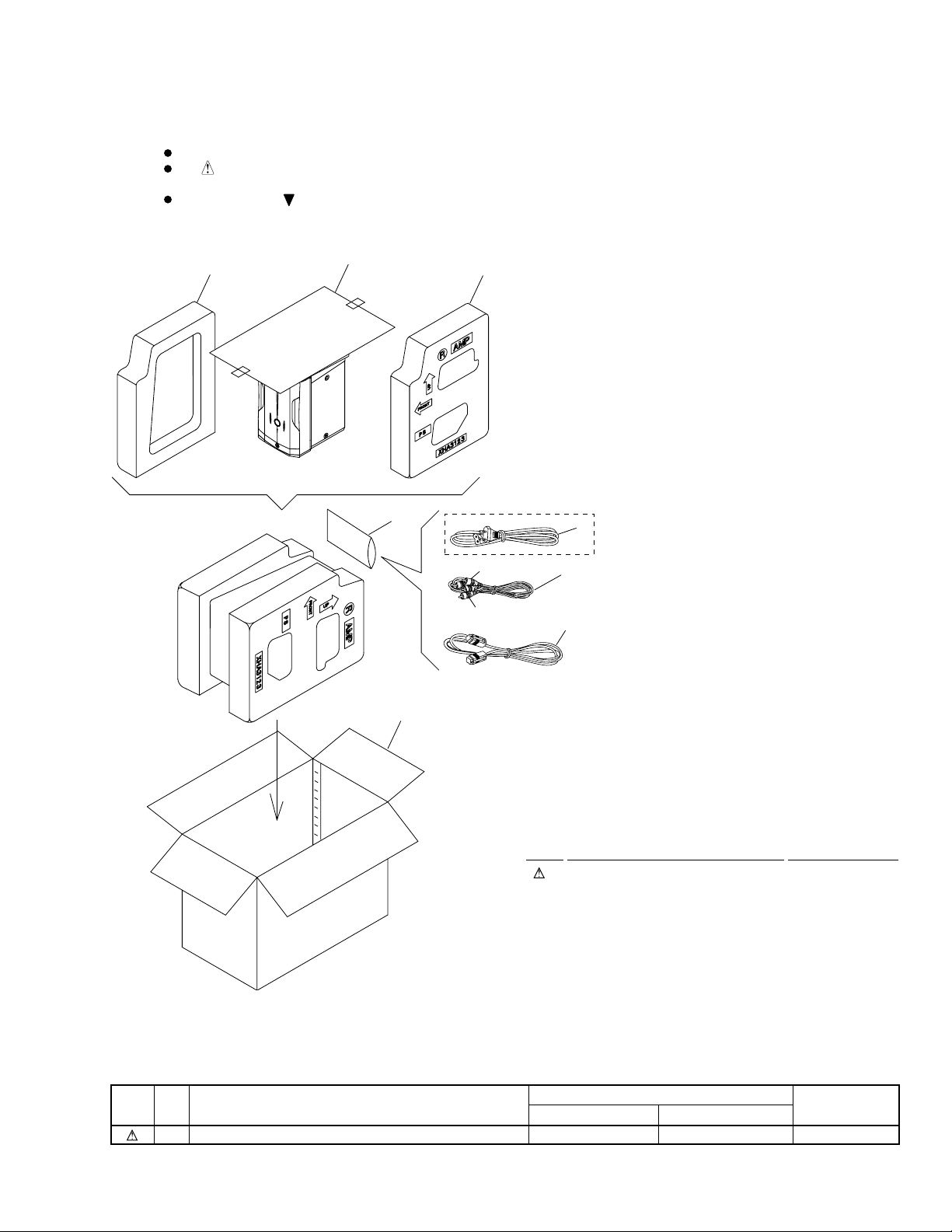
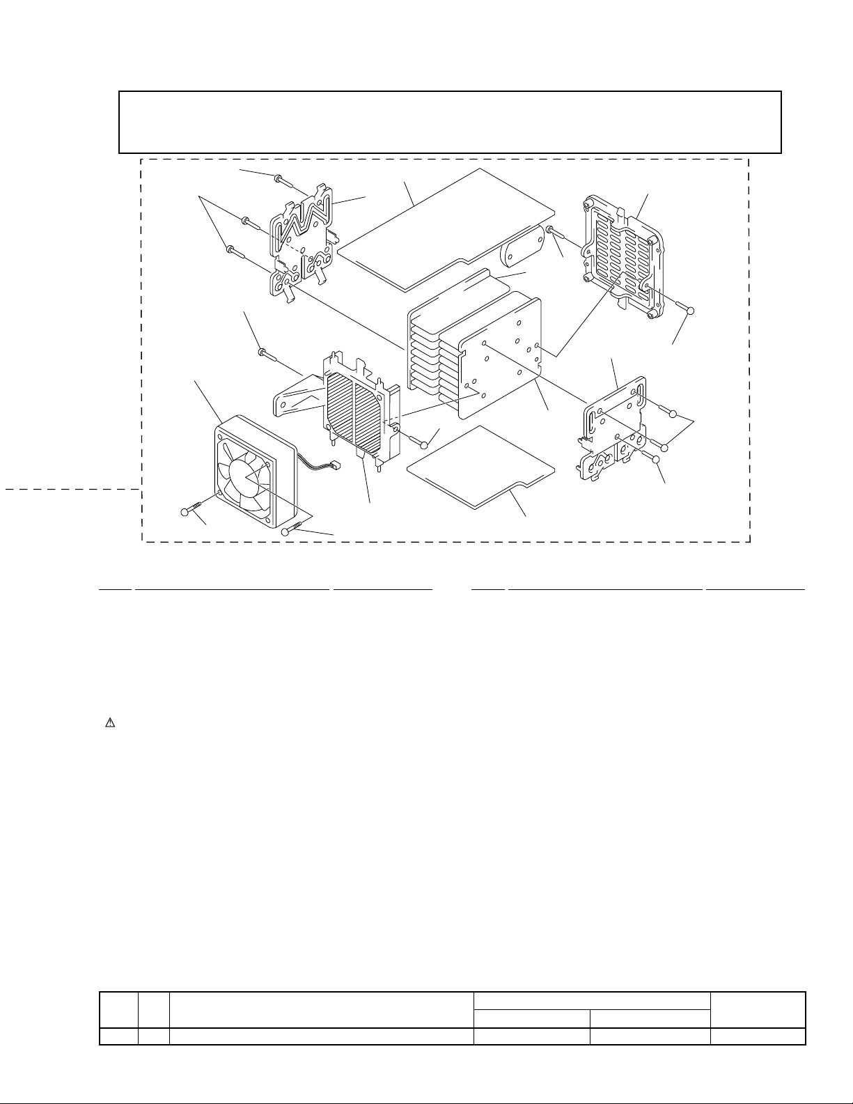
2. EXPLODED VIEWS AND PARTS LIST
NOTES:
2.1 PACKING
Parts marked by "NSP" are generally unavailable because they are not in our Master Spare Parts List.
The mark found on some component parts indicates the importance of the safety factor of the part.
Therefore, when replacing, be sure to use parts of identical designation.
Screws adjacent to mark on product are used for disassembly.
6
5
7
M-IS22
4
8
MYXJ T ype Only
Red
White
1
2
3
(1) PACKING PARTS LIST
Mark No. Description Part No.
1 Power Cord See Contrast table (2)
2 RCA pin-plug stereo cable PDE1126
(L=1m)
NSP 4 Polyethylene Bag Z21-038
3 System Cable XDE3042
5 Packing Sheet AHG7053
6 Protector L(A) XHA3122
7 Protector R(A) XHA3123
8 Packing Case A(MY) XHD3170
(2) CONTRAST TABLE
M-IS22/MYXJ and NVXJ are constructed the same except for the following :
Mark No. Symbol and Description
1 Power Cord ADG1154 Not used
MYXJ Type NVXJ Type
Part No.
Remarks
3
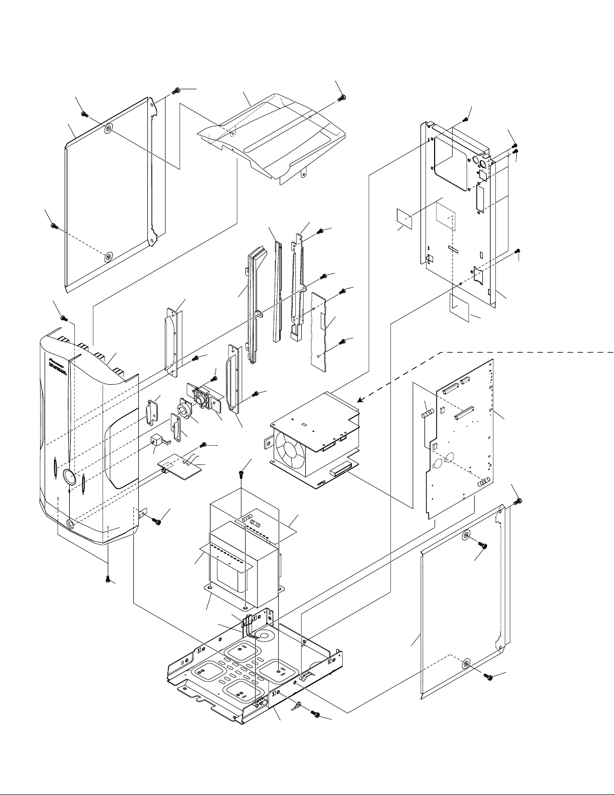
M-IS22
2.2 EXTERIOR
37
31
41
41
30
24
41
39
39
22
29
23
18
41
39
39
37
37
38
32
41
39
15
7
39
42
NVXJ Only
44
21
26
41
27
39
20
28
5
8
25
33
35
6
4
19
43
31
9
1
C11
C12
37
41
41
11
41
4
M-IS22
Caution when disassemble.
Even if the power supply code is pulled out from the outlet, neither C11 nor C12 of AF ASSY are discharged.
Please discharge C11 and C12 of AF ASSY by the resistor of 100 Ω or more before removing AF ASSY or POWER SUPPLY ASSY.
There is a possibility to destroy the transistor, and Please discharge by the resistor of 100 Ω or more.
10
36
40
36
34
40
16
12
2
14
34
14
3
(1) EXTERIOR PARTS LIST
Mark No. Description Part No.
NSP 1 MAIN Assy XWZ3418
NSP 2 AMP Assy XWZ3419
NSP 3 POWER SUPPLY Assy XWZ3420
NSP 4 PRIMARY Assy XWZ3421
NSP 5 SECONDARY Assy XWZ3422
NSP 6 HP Assy XWZ3423
NSP 7 BLUE LED Assy XWZ3488
8 Pow er Transformer A TS7247
9 Fuse (FU1 : 3.15A) REK1027
10 DC Fan Motor AXM7014
NSP 11 Chassis A ANA7086
12 Holder ANG7009
13 Power Pac Holder ANG7109
14 Heat Sink ANH7058
15 Rear Panel A (MY) XNC3107
16 Mold A AMR7005
17 Mold B AMR7006
18 Reflector A XMR3041
19 Binder ZCA-SKB90BK
20 Standby Button XAD3096
(2) CONTRAST TABLE
M-IS22/MYXJ and NVXJ are constructed the same except for the following :
Mark No. Symbol and Description
42 Name Label Not used XAL3088
Mark No. Description Part No.
21 Standby Lens XAK3193
22 AMP Lens XAK3194
23 LT Conductor A XAK3219
24 Side Duct L XAK3220
25 Side Duct R XAK3221
26 AMP T win L XAK3222
27 AMP T win R XAK3223
28 AMP Escutcheon XAK3226
29 Top Panel XAN3031
30 Front P anel A XMB3046
31 Side Bonnet ANE7242
NSP 32 ICP Label AAX7738
33 Screw With Washer ABA1005
34 Screw ABA1021
35 Screw BBT40P060FZK
36 Screw BBZ30P180FMC
37 Screw BPZ30P080FZK
38 Screw BMZ30P060FZK
39 Screw BPZ30P100FZK
40 Screw BPZ30P350FZK
41 Screw VBZ30P060FZK
42 Name Label See Contrast table (2)
NSP 43 BIND Assy • • • • •
44 Screw BBZ30P080FMC
MYXJ Type NVXJ Type
34
Part No.
13
17
34
36
36
Remarks
5
1
23
M-IS22
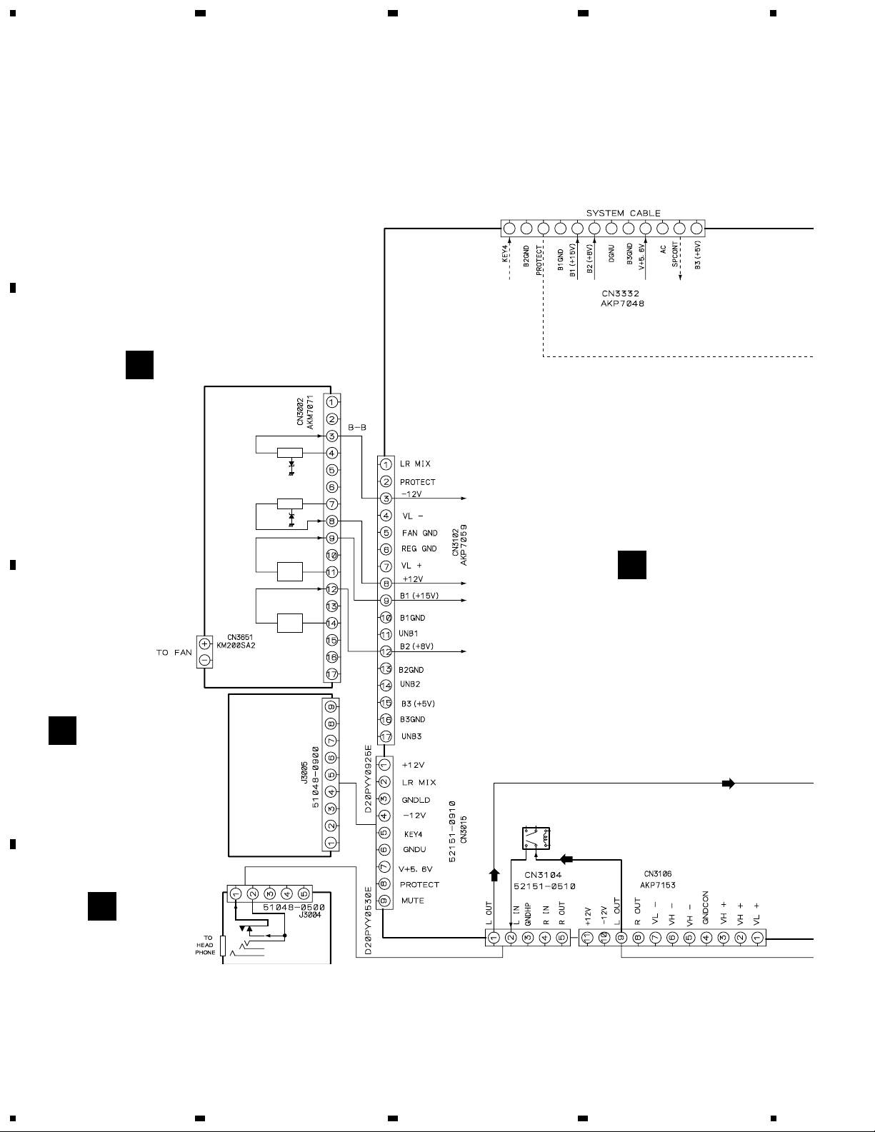
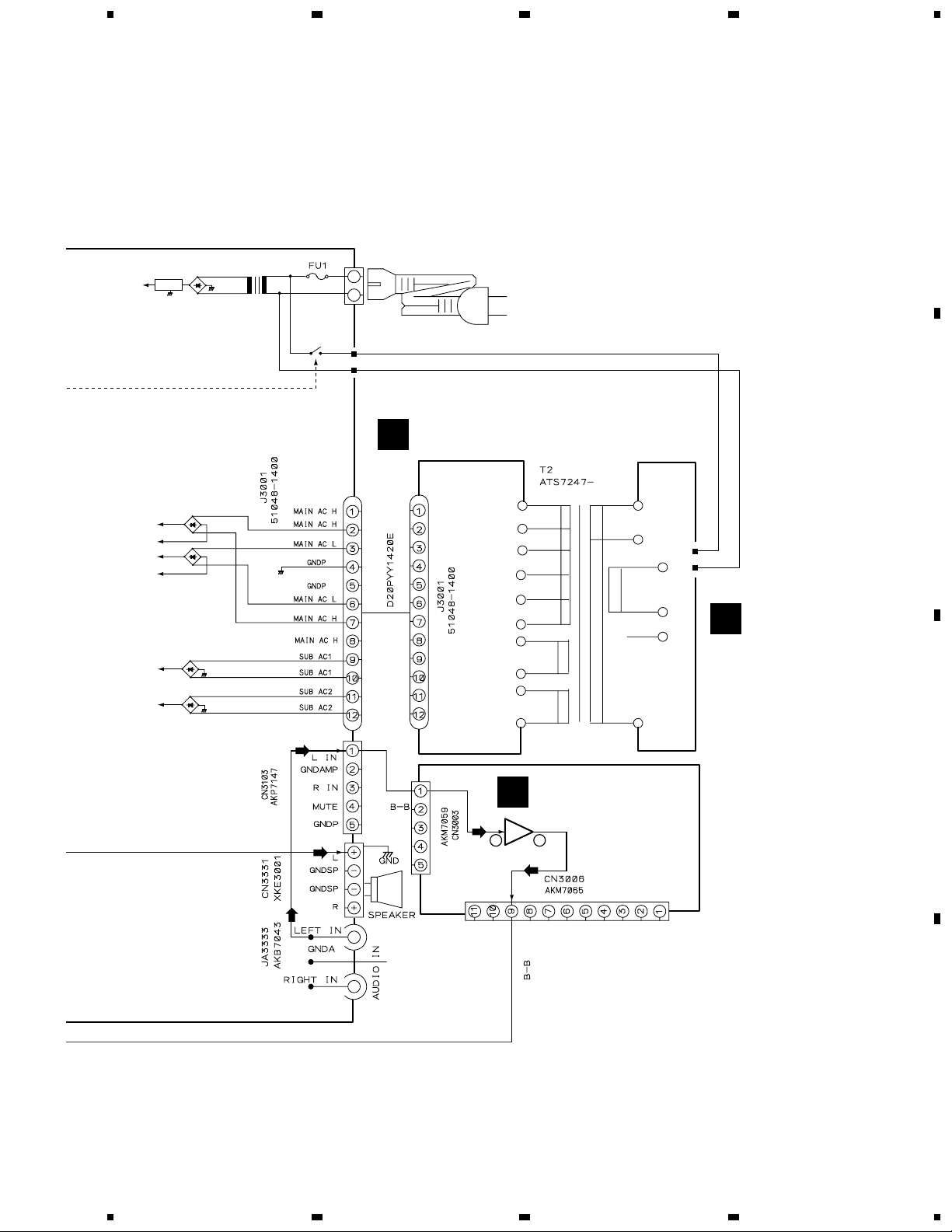
3. SCHEMATIC DIAGRAM
A
3.1 OVERALL WIRING CONNECTION DIAGRAM
POWER SUPPLY ASSY
G
(XWZ3420)
B
-12V VLIC24
4
+15V +8V V+5.6V
+12V VL+
IC23
+15V UNB1
IC35
Q33
+8V UNB2
IC35
Q43
C
-12V
+12V
+12V
+12V
MAIN ASSY
A
(XWZ3418)
BLUE LED ASSY
E
(XWZ3488)
SPEAKER RELAY
RY3601
(ASR7008)
HP ASSY
D
(XWZ3423)
D
6
1234
5
Note : When ordering service parts, be sure to refer to "EXPLODED VIEWS and PARTS LIST" or "PCB PARTS LIST"
V+5.6V
IC82
D81-D84
T1
BKP1046
RY81
AN1
678
SECONDARY ASSY
C
(XWZ3422)
M-IS22
A
B
VH+
VH-
VL+
VL-
UNB1
UNB2
D31–D34
D41–D44
D11
D21
AMP ASSY
F
(XWZ3419)
POWER AMP.
610
IC3301
(STK407-070)
PRIMARY ASSY
B
(XWZ3421)
C
D
7
5
6
7
8

1
23
M-IS22
3.2 MAIN, PRIMARY, SECONDARY, HP and BLUE LED ASSYS
A
MAIN ASSY
A
(XWZ3418)
CN3003
F
B
4
CN3006
F
C
CN3002
G
D
8
A
1234

5
: AUDIO SIGNAL ROUTE
678
M-IS22
A
HP ASSY
D
(XWZ3423)
B
SECONDARY ASSY
(XWZ3422)
C
REK1027
(T3.15A)
BLUE LED ASSY
S560 : STANDBY/ON
E
BLUE LED
ASSY
(XWZ3488)
PRIMARY ASSY
B
(XWZ3421)
CAUTION :
FOR CONTINUED PROTECTION AGAINST
RISK OF FIRE, REPLACE ONLY WITH SAME
TYPE NO. 491007, MFD BY LITTELFUSE INK.
FOR IC11, IC12 (AEK7021).
CAUTION :
FOR CONTINUED PROTECTION AGAINST
RISK OF FIRE, REPLACE ONLY WITH SAME
TYPE NO. 491005, MFD BY LITTELFUSE INK.
FOR IC21, IC22 (AEK7019).
CAUTION :
FOR CONTINUED PROTECTION AGAINST
RISK OF FIRE, REPLACE ONLY WITH SAME
TYPE NO. 491004, MFD BY LITTELFUSE INK.
FOR IC31 (AEK7018).
AC POWER CORD
MYXJ TYPE : ADG1154
NVXJ TYPE : ADG1156
AC220-230V
C
CAUTION :
FOR CONTINUED PROTECTION AGAINST
RISK OF FIRE, REPLACE ONLY WITH SAME
TYPE NO. 49103.5, MFD BY LITTELFUSE
• NOTE FOR FUSE REPLACEMENT
CAUTION -
FOR CONTINUED PROTECTION AGAINST RISK OF FIRE.
REPLACE WITH SAME TYPE AND RATINGS ONLY.
INK. FOR IC41 (AEK7017).
EDCBA
5
6
7
8
D
9

1
23
M-IS22
3.3 AMP and POWER SUPPLY ASSYS
4
A
B
F
AMP ASSY
(XWZ3419)
: AUDIO SIGNAL ROUTE
CN3103
A
C
CN3106
A
D
10
F
1234

5
678
M-IS22
A
POWER SUPPLY ASSY
G
(XWZ3420)
CAUTION :
FOR CONTINUED PROTECTION AGAINST
RISK OF FIRE, REPLACE ONLY WITH SAME
TYPE NO. 4911.25, MFD BY LITTELFUSE
INK. FOR IC33 (AEK7048).
CAUTION :
FOR CONTINUED PROTECTION AGAINST
RISK OF FIRE, REPLACE ONLY WITH SAME
TYPE NO. 491002, MFD BY LITTELFUSE INK.
FOR IC42 (AEK7067).
B
C
CN3102
A
D
G
5
6
7
8
11

1
23
M-IS22
4. PCB CONNECTION DIAGRAM
NOTE FOR PCB DIAGRAMS:
A
1. Part numbers in PCB diagrams match those in the schematic
diagrams.
2. A comparison between the main parts of PCB and schematic
diagrams is shown below.
Symbol in PCB
Diagrams
BCE
Symbol in Schematic
Diagrams
BCE
BCE
Part Name
Transistor
3. The parts mounted on this PCB include all necessary parts
for several destination.
For further information for respective destinations, be sure
to check with the schematic diagram.
4. Viewpoint of PCB diagrams
Connector
4
Capacitor
SIDE A
BCEBCE
BCE
DGSDGS
DGS
B
Transistor
with resistor
Field effect
transistor
Resistor array
3-terminal
regulator
P.C.Board Chip Part
4.1 PRIMARY and SECONDARY ASSYS
C
SECONDARY ASSY
SIDE B
B
PRIMARY ASSY
C
A
J3001
POWER TRANSFORMER
(XNP3050-B)
D
12
B C
SIDE A
A
A
N BLUE
1234
L BROWN

1
(XNP3050-B)
HP ASSY
D
HP ASSY
D
SIDE B
Q5602
Q5604
Q5601
Q5603
IC5601
(XNP3050-B)
BLUE LED ASSY
E
BLUE LED ASSY
E
CN3104
A
CN3015
A
SIDE A
4.2 HP and BLUE LED ASSYS
234
M-IS22
A
B
1
2
3
C
D
ED
4
13

1
M-IS22
4.3 MAIN ASSY
23
4
A
IC3302
CN3006
F
F
CN3003
D
J3004
XC-IS22CD
G
B
CN3002
E
J3005
C
MAIN
ASSY
L BROWN
N BLUE
AC IN
D
A
IC81
IC82
Q81
B
B
C
J3001
NEUTRAL
LIVE
SIDE A
(XNP3050-B)
14
A
1234

A
1
234
M-IS22
MAIN
ASSY
SIDE B
(XNP3050-B)
Q3313
Q3602
Q85
Q3603
Q3601
Q3607
Q3608
Q3606
Q3605
Q3621
A
B
Q82
C
D
A
1
2
3
4
15

1
23
M-IS22
4.4 AMP and POWER SUPPLY ASSYS
4
G
A
POWER
IC24
IC23
Q33
Q43
SUPPLY
ASSY
Q42
Q32
Q3651
Q53
Q3654
B
IC52
IC33
IC42
A
CN3102
A
CN3106
F
C
AMP
A
CN3103
Q3502
Q3501
ASSY
IC3301
D
SIDE A
(XNP3050-B)
16
F G
Q3352
Q3351
1234

1
234
M-IS22
G
IC32
Q31
Q41
IC61
Q3652
Q3653
Q51
POWER
SUPPLY
ASSY
A
B
Q3311
Q3312
Q3503
IC3502
IC3501
Q3353
Q3354
F
AMP
ASSY
SIDE B
(XNP3050-B)
C
D
GF
1
2
3
4
17

M-IS22
5. PCB PARTS LIST
NOTES:
Parts marked by "NSP" are generally unavailable because they are not in our Master Spare Parts List.
The mark found on some component parts indicates the importance of the safety factor of the part.
Therefore, when replacing, be sure to use parts of identical designation.
When ordering resistors, first convert resistance values into code form as shown in the following examples.
Ex.1 When there are 2 effective digits (any digit apart from 0), such as 560 ohm and 47k ohm (tolerance is shown by J=5%,
and K=10%).
560
47k
0.5
1
56 x 10
47 x 103
R50
1R0
Ex.2 When there are 3 effective digits (such as in high precision metal film resistors).
5.62k RN1/4PC F562 x 10
1
561
473
RD1/4PU J
RD1/4PU J
RN2H K
RS1P K
1
5621
561
473
R50
1R0
5621
Mark No. Description Part No.
LIST OF ASSEMBLIES
NSP MAIN ASSY XWK3030
NSP MAIN ASSY XWZ3418
NSP AMP ASSY XWZ3419
NSP POWER SUPPLY ASSY XWZ3420
NSP PRIMARY ASSY XWZ3421
NSP SECONDARY ASSY XWZ3422
NSP HP ASSY XWZ3423
NSP BLUE LED ASSY XWZ3488
MAIN ASSY
A
SEMICONDUCTORS
IC82 NJM78M56FA
Q3601, Q3621 2SA1037K
Q3602, Q3603, Q3605–Q3608 2SC2412K
Q81 2SD1859X
Q85 DTA114TK
Q3313 DTA124EK
Q82 DTC124EK
D3601, D3603, D3609, D3621 1SS133
D3625, D3626, D3651, D3652 1SS133
D85–D87 1SS133
D11, D21 D3SBA20(B)
D3608 MTZJ5.6C
D31–D34, D41–D44 S5566G(TPB2)
D81–D84 S5688G
COILS AND FILTERS
L1 LINE FILTER ATF7019
L3331–L3334 (1µH) ATH-133
TRANSFORMERS
T1 ST ANDBY TRANSFORMER XTT3004
SWITCHES AND RELAYS
RY3601 SP RELAY/12V ASR7008
RY81 ASR7018
Mark No. Description Part No.
CAPACITORS
C1–C3 (10000pF/AC275V) ACE7013
C3345, C3346 (10000pF/100V) ACG7021
C11, C12 (2200µF/71v) ACH7117
C3551–C3554 CCSRCH331J50
C3602, C84 CEAT100M50
C83 CEAT1R0M50
C3601 CEAT221M16
C41 CEAT222M25
C31 CEAT222M35
C3621 CEAT2R2M2A
C21, C22 CEAT332M35
C82 CEAT471M25
C3325 CEATR10M50
C3335–C3338 CKSRYB103K50
C3331–C3334 CKSRYB104K25
C9011 CQMA102K2E
C9021 CQMA223K2E
RESISTORS
R3333, R3334 RD1/4MUF101J
R82 RD1/4PU220J
R3601, R3602 RS3LMFR22J
Other Resistors RS1/16S&&&J
OTHERS
CN3015 9P JUMPER CONNECTOR 52151-0910
JA3333 2P PIN JACK AKB7043
CN3332 10P SOCKET AKP7048
CN3103 5P CONNECTOR SOCKET AKP7147
CN3106 14P SOCKET AKP7153
CN3102 17P CONNECTOR SOCKET AKP7159
H1, H2 FUSE CLIP AKR7001
AN1 AC INLET 1P BKP1046
J3001 JUMPER WIRE D20PYY1420E
BARRIER CAP XEC3023
CN3331 4P SPEAKER TERMINAL XKE3001
18

M-IS22
Mark No. Description Part No.
PRIMARY ASSY
B
PRIMARY assembly has no service part.
SECONDARY ASSY
C
SEMICONDUCTORS
IC41 PROTECTOR(3.5A) AEK7017
IC31 PROTECTOR(4A) AEK7018
IC21, IC22 PROTECTOR(5A) AEK7019
IC11, IC12 PROTECTOR(7A) AEK7021
HP ASSY
D
COILS AND FILTERS
L3992–L3994 CHIP BEADS VTL1096
CAPACITORS
C3991, C3995, C3996 CKSRYB472K50
RESISTORS
R3991, R3992 RS2LMF331J
OTHERS
3004 5P CABLE HOLDER 51048-0500
3991 MINI JACK AKN7003
J3004 5P JUMPER WIRE D20PYY0530E
BULE LED ASSY
E
SEMICONDUCTORS
Q5601, Q5603 2SC2412K
Q5602 DTC124EK
D5607, D5608 1SS355
D5603 E1L4E-7B1A(2345)
D5604 SLR-343VC(NPQ)
SWITCHES AND RELAYS
S5601 ASG7013
Mark No. Description Part No.
AMP ASSY
F
SEMICONDUCTORS
IC3501, IC3502 BA4558F-HT
IC3301 STK407-070B
Q3354 2SA1037K
Q3353 2SC2412K
Q3311, Q3312 2SD2114K
Q3501, Q3502 2SK246
Q3503 DTA124EK
Q3351 IRFI9Z34G
Q3352 IRFIZ34G
D3301, D3302 1SR139-100
D3351–D3354, D3361, D3362 1SS133
D3355, D3356 LT2A03
D3357, D3358 MTZJ10C
D3359, D3360 MTZJ18B
D3363, D3364 MTZJ39C
CAPACITORS
C3327, C3328 CCSRCH680J50
C3317, C3318 CEANP100M35
C3313, C3314 CEANPR47M50
C3303, C3304 CEAT101M50
C3506–C3508 CEAT1R0M50
C3501, C3502, C3509, C3510 CEAT470M25
C3315, C3316 CKSRYB332K50
C3503, C3504 CKSRYB682K50
C3308 CKSRYB822K50
RESISTORS
R3353, R3354 RD1/4PU101J
R3510 RD1/4PU104J
Other Resistors RS1/16S&&&J
OTHERS
CN3003 5P CONNECTOR PLUG AKM7059
CN3006 11P CONNECTOR PLUG AKM7065
RESISTORS
R5626 RD1/4PU332J
Other Resistors RS1/16S&&&J
OTHERS
302 9P CABLE HOLDER 51048-0900
J3005 JUMPER WIRE D20PYY0925E
LED SPACER XEB3018
POWER SUPPLY ASSY
G
SEMICONDUCTORS
IC33 PROTECTOR(1.25A) AEK7048
IC42 PROTECTOR(2A) AEK7067
IC32 BA4558F-HT
IC23 NJM7805FA
IC24 NJM7905FA
Q33, Q43 2SB1375
Q32, Q3654, Q42 2SC1740S
Q3652 2SC2412K
Q3651 DTA143ES
Q3653 DTC124EK
19

M-IS22
Mark No. Description Part No.
D3654–D3656, D9021–D9024, D9026 1SS133
D9029 1SS133
D9030 MTZJ24B
D36, D46 MTZJ3.0B
D35, D45 MTZJ5.1B
D9027, D9028 MTZJ6.8C
CAPACITORS
C27, C28, C35, C45 CEAT100M50
C3652 CEAT101M16
C25, C26, C3651 CEAT1R0M50
C3654 CEAT220M50
C42, C43 CEAT470M16
C32, C33 CEAT470M25
C44 CKSRYB102K50
C3653, C9027, C9028 CKSRYB104K25
RESISTORS
R35 RD1/2LMF121J
R45 RD1/2LMF820J
R3659 RD1/2PM330J
Other Resistors RS1/16S&&&J
OTHERS
CN3002 17P CONNECTOR PLUG AKM7071
CN3651 2P PLUG KM200SA2
6. ADJUSTMENT
There is no information to be shown in this chapter.
20

7. GENERAL INFORMATION
MAIN
ASSY
A
INPUT SIGNAL
10mV
OUTPUT SIGNAL
R85 – 1kΩ
CONTROLL
0V, 5V or 12V
CONNECT
A POINT (GND)
(FOUR PLACES)
SIDE B
7.1 SINGLE OPERATION METHOD
Single operation method and inputlevel.
The procedure and the input level of a single operation are shown below.
1. R85 are shorted by 1kΩ.
2. A point of the figure below in four places is connected.
GND is not common because it is independent with chassis GND (GND of the amplifier), B1GND, B2GND, and B3GND.
The potential of B1GND, B2GND, and B3GND is done by connecting A point in four places as well as chassis GND.
2. The power supply of the product is turned on.
3. The terminal CONT (2 pin of CN3332) are controlled respectively by the following voltages.
CONT
12V 5V 0V
RY ON ON OFF
MUTE OFF ON ON
4. The signal of 10mV is input from input terminal (JA3333), and the output is confirmed with speaker terminal (CN3331).
Note :If the music signal is input directly to input terminal (JA3333) with CD PLAYER etc. , the output becomes a large volume because
there are 40dB GAIN of the amplifier.
M-IS22
Caution when disassemble.
Even if the power supply code is pulled out from the outlet, neither C11 nor C12 of AF ASSY are discharged.
Please discharge C11 and C12 of AF ASSY by the resistor of 100 Ω or more before removing AF ASSY or POWER SUPPLY ASSY.
There is a possibility to destroy the transistor, and Please discharge by the resistor of 100 Ω or more.
21

M-IS22
8. PANEL FACILITIES AND SPECIFICATIONS
¶ SPECIFICATIONS¶ PANEL FACILITIES
Amplifier section
Continuous Power (RMS)............. 100 W + 100 W
POWER AMPLIFIER M-IS22
30
31
AERO DUCT CONSTRUCTION
STANDBY/ON
STANDBY
29
P
H
O
N
E
S
Continuous Power (DIN) .................. 65 W + 65 W
Music Power (DIN)....................... 150 W + 150 W
Miscellaneous
Power Requirements.......AC 220-230 V, 50/60 Hz
Power Consumption ....................................140 W
Power Consumption in standby mode.............1 W
Dimensions:
Power Amplifier . 160 (W) x 300 (H) x 237 (D) mm
Weight:
Power Amplifier ........................................... 4.1 kg
Accessories
Power cord (MYXJ Type)..................................... 1
System cable ...................................................... 1
RCA pin-plug stereo cable ..................................1
(1 kHz, THD 10%, 6 Ω)
(1 kHz, THD 1%, 6 Ω)
(1 kHz, THD 1%, 6 Ω)
29 STANDBY/ON
30 Standby indicator
31 Headphone jack
Note
Specifications and design subject to possible
modification without notice, due to improvements.
22
 Loading...