

Page 1

REMIX STATION
RMX-1000
http://pioneerdj.com/support/
The Pioneer website shown above offers FAQs, information on software and various other types of information
and services to allow you to use your product in greater comfort.
Operating Instructions
Page 2

Thank you for buying this Pioneer product. Please read through these operating instructions so you will know how to operate your model properly. After
you have finished reading the instructions, put them away in a safe place for future reference.
In some countries or regions, the shape of the power plug and power outlet may sometimes differ from that shown in the explanatory drawings.
However the method of connecting and operating the unit is the same.
IMPORTANT
CAUTION
RISK OF ELECTRIC SHOCK
DO NOT OPEN
The lightning flash with arrowhead symbol,
within an equilateral triangle, is intended to
alert the user to the presence of uninsulated
“dangerous voltage” within the product’s
enclosure that may be of sufficient
magnitude to constitute a risk of electric
shock to persons.
Read these instructions.
1)
Keep these instructions.
2)
Heed all warnings.
3)
Follow all instructions.
4)
Do not use this apparatus near water.
5)
Clean only with dry cloth.
6)
Do not block any ventilation openings. Install in
7)
CAUTION:
TO PREVENT THE RISK OF ELECTRIC
SHOCK, DO NOT REMOVE COVER (OR
BACK). NO USER-SERVICEABLE PARTS
INSIDE. REFER SERVICING TO QUALIFIED
SERVICE PERSONNEL.
accordance with the manufacturer’s
instructions.
Do not install near any heat sources such as
8)
radiators, heat registers, stoves, or other
apparatus (including amplifiers) that produce
heat.
Do not defeat the safety purpose of the polarized
9)
or grounding-type plug. A polarized plug has two
blades with one wider than the other. A
grounding type plug has two blades and a third
grounding prong. The wide blade or the third
prong are provided for your safety. If the provided
plug does not fit into your outlet, consult an
electrician for replacement of the obsolete outlet.
Protect the power cord from being walked on or
10)
pinched particularly at plugs, convenience
receptacles, and the point where they exit from
the apparatus.
11)
Only use attachments/accessories specified by
the manufacturer.
12)
Use only with the cart, stand, tripod, bracket, or
table specified by the manufacturer, or sold with
the apparatus. When a cart is used, use caution
when moving the cart/apparatus combination to
avoid injury from tip-over.
13)
Unplug this apparatus during lightning storms
or when unused for long periods of time.
14)
Refer all servicing to qualified service personnel.
Servicing is required when the apparatus has
been damaged in any way, such as power-supply
cord or plug is damaged, liquid has been spilled
or objects have fallen into the apparatus, the
apparatus has been exposed to rain or moisture,
does not operate normally, or has been dropped.
The exclamation point within an equilateral
triangle is intended to alert the user to the
presence of important operating and
maintenance (servicing) instructions in the
literature accompanying the appliance.
D3-4-2-1-1_A1_En
D3-7-13-69_En
FEDERAL COMMUNICATIONS COMMISSION DECLARATION OF CONFORMITY
This device complies with part 15 of the FCC Rules. Operation is subject to the following two conditions: (1) This
device may not cause harmful interference, and (2) this device must accept any interference received, including
interference that may cause undesired operation.
Product Name: REMIX STATION
Model Number: RMX-1000
Responsible Party Name: PIONEER ELECTRONICS (USA) INC.
SERVICE SUPPORT DIVISION
Address: 1925 E. DOMINGUEZ ST. LONG BEACH, CA 90810-1003, U.S.A.
Phone: 1-800-421-1404
URL: http://www.pioneerelectronics.com
En
2
D8-10-4*_C1_En
Page 3

NOTE:
This equipment has been tested and found to comply with the limits for a Class B digital device, pursuant to Part 15
of the FCC Rules. These limits are designed to provide reasonable protection against harmful interference in a
residential installation. This equipment generates, uses, and can radiate radio frequency energy and, if not installed
and used in accordance with the instructions, may cause harmful interference to radio communications. However,
there is no guarantee that interference will not occur in a particular installation. If this equipment does cause
harmful interference to radio or television reception, which can be determined by turning the equipment off and on,
the user is encouraged to try to correct the interference by one or more of the following measures:
— Reorient or relocate the receiving antenna.
— Increase the separation between the equipment and receiver.
— Connect the equipment into an outlet on a circuit different from that to which the receiver is connected.
— Consult the dealer or an experienced radio/TV technician for help.
D8-10-1-2_A1_En
WARNING
This equipment is not waterproof. To prevent a fire or
shock hazard, do not place any container filled with
liquid near this equipment (such as a vase or flower
pot) or expose it to dripping, splashing, rain or
moisture.
D3-4-2-1-3_A1_En
WARNING
Before plugging in for the first time, read the following
section carefully.
The voltage of the available power supply differs
according to country or region. Be sure that the
power supply voltage of the area where this unit
will be used meets the required voltage (e.g., 230 V
or 120 V) written on the the AC adapter’s label.
D3-4-2-1-4*_A1_En_PSV
WARNING
To prevent a fire hazard, do not place any naked flame
sources (such as a lighted candle) on the equipment.
D3-4-2-1-7a_A1_En
Operating Environment
Operating environment temperature and humidity:
+5 °C to +35 °C (+41 °F to +95 °F); less than 85 %RH
(cooling vents not blocked)
Do not install this unit in a poorly ventilated area, or in
locations exposed to high humidity or direct sunlight (or
strong artificial light)
If the AC plug of this unit does not match the AC
outlet you want to use, the plug must be removed
and appropriate one fitted. Replacement and
mounting of an AC plug on the power supply cord of
this unit should be performed only by qualified
service personnel. If connected to an AC outlet, the
cut-off plug can cause severe electrical shock. Make
sure it is properly disposed of after removal.
The equipment should be disconnected by removing
the mains plug from the wall socket when left unused
for a long period of time (for example, when on
vacation).
IMPORTANT NOTICE
THE MODEL NUMBER AND SERIAL NUMBER OF
THIS EQUIPMENT ARE ON THE REAR OR BOTTOM.
RECORD THESE NUMBERS ON PAGE 27 FOR
FUTURE REFERENCE.
D3-4-2-1-7c*_A1_En
D3-4-2-2-1a_A1_En
D36-AP9-1_A1_En_PSV
CAUTION
The ON, STANDBY switch on this unit will not
completely shut off all power from the AC outlet.
Since the power cord serves as the main disconnect
device for the unit, you will need to unplug it from the
AC outlet to shut down all power. Therefore, make
sure the unit has been installed so that the power
cord can be easily unplugged from the AC outlet in
case of an accident. To avoid fire hazard, the power
cord should also be unplugged from the AC outlet
when left unused for a long period of time (for
example, when on vacation).
D3-4-2-2-2a*_A1_En
When using this product, confirm the safety
information shown on the bottom of the unit.
D3-4-2-2-4_B1_En
Information to User
Alterations or modifications carried out without
appropriate authorization may invalidate the user’s
right to operate the equipment.
D8-10-2_A1_En
WARNING: Handling the cord on this product or
cords associated with accessories sold with the
product may expose you to chemicals listed on
proposition 65 known to the State of California and
other governmental entities to cause cancer and
birth defect or other reproductive harm.
D36-P5_B1_En
CAUTION
This product satisfies FCC regulations when shielded
cables and connectors are used to connect the unit
to other equipment. To prevent electromagnetic
interference with electric appliances such as radios
and televisions, use shielded cables and connectors
for connections.
D8-10-3a_A1_En
This Class B digital apparatus complies with
Canadian ICES-003.
D8-10-1-3_A1_En
En
3
Page 4

POWER-CORD CAUTION
Handle the power cord by the plug. Do not pull out the
POWER-CORD CAUTION
Handle the power cord by the plug. Do not pull out the
plug by tugging the cord and never touch the power
plug by tugging the cord and never touch the power
cord when your hands are wet as this could cause a
cord when your hands are wet as this could cause a
short circuit or electric shock. Do not place the unit, a
short circuit or electric shock. Do not place the unit, a
piece of furniture, etc., on the power cord, or pinch the
piece of furniture, etc., on the power cord, or pinch the
cord. Never make a knot in the cord or tie it with other
cord. Never make a knot in the cord or tie it with other
cords. The power cords should be routed such that they
cords. The power cords should be routed such that they
are not likely to be stepped on. A damaged power cord
are not likely to be stepped on. A damaged power cord
can cause a fire or give you an electrical shock. Check
can cause a fire or give you an electrical shock. Check
the power cord once in a while. When you find it
the power cord once in a while. When you find it
damaged, ask your nearest PIONEER authorized
damaged, ask your nearest PIONEER authorized
service center or your dealer for a replacement.
service center or your dealer for a replacement.
The Safety of Your Ears is in Your Hands
Get the most out of your equipment by playing it at a
safe level – a level that lets the sound come through
clearly without annoying blaring or distortion and, most
importantly, without affecting your sensitive hearing.
Sound can be deceiving. Over time, your hearing
“comfort level” adapts to higher volumes of sound, so
what sounds “normal” can actually be loud and
harmful to your hearing. Guard against this by setting
your equipment at a safe level BEFORE your hearing
adapts.
ESTABLISH A SAFE LEVEL:
• Set your volume control at a low setting.
• Slowly increase the sound until you can hear it
comfortably and clearly, without distortion.
• Once you have established a comfortable sound
level, set the dial and leave it there.
S002*_A1_En
S002*_A1_En
BE SURE TO OBSERVE THE FOLLOWING
GUIDELINES:
• Do not turn up the volume so high that you can’t
hear what’s around you.
• Use caution or temporarily discontinue use in
potentially hazardous situations.
• Do not use headphones while operating a motorized
vehicle; the use of headphones may create a traffic
hazard and is illegal in many areas.
S001a_A1_En
En
4
Page 5

Contents
How to read this manual
The names of displays, menus, and buttons in this manual are enclosed
in brackets. (e.g. [MASTER] channel, [ON/OFF], [File] menu)
Quick Start Guide
Features ....................................................................................................... 6
Operation overview ..................................................................................... 6
What’s in the box ........................................................................................ 6
Connecting the input/output terminals .................................................... 7
Preparations for using the effects ............................................................. 9
Using the SCENE FX function ................................................................... 9
Using the ISOLATE FX function ................................................................. 9
Using the X-PAD FX function ..................................................................... 9
Using the RELEASE FX function ............................................................... 9
Operation
Adjusting the input and output levels ..................................................... 11
Making the BPM and QUANTIZE settings ............................................. 11
SCENE FX section ..................................................................................... 12
ISOLATE FX section .................................................................................. 13
X-PAD FX section ...................................................................................... 13
RELEASE FX section ................................................................................. 15
FX SOURCE section .................................................................................. 15
FX SETTING section .................................................................................. 15
Types of effects
Types of SCENE FX effects ....................................................................... 16
Types of ISOLATE FX effects .................................................................... 17
Types of X-PAD FX effects ........................................................................ 18
Types of RELEASE FX effects ................................................................... 18
Using the included software
Software end user license agreement .................................................... 19
Using remixbox ......................................................................................... 20
Checking the latest information on the included software .................. 21
Changing this unit’s settings
Changing the MIDI settings ..................................................................... 22
Using the update function ....................................................................... 22
MIDI assignment map
Additional information
Troubleshooting ........................................................................................ 25
Block Diagram .......................................................................................... 26
About trademarks and registered trademarks ...................................... 26
Cautions on copyrights ............................................................................ 26
Disclaimer ................................................................................................. 26
Specifications............................................................................................ 26
En
5
Page 6

Quick Start Guide
Features
This unit is a remixing station for DJs consisting of four effect sections. It
allows tracks to be arranged in real time with intuitive operation.
SCENE FX
Through the operation of turning the control, new sounds can be added
to the currently playing track and breaks can be created at the desired
positions to achieve a new sound for the track. Ten types of effects and
two sub parameters can be combined to achieve highly individualistic
DJ remixing performances.
ISOLATE FX
The sounds of specific instruments can be isolated and their rhythm and
tone changed in the same way as a DJ mixer’s EQ controls are operated.
One of four effects can be selected and applied at separate rates for the
low, mid and high frequencies.
X-PAD FX
By operating the touchpad, new sounds can be added to the original
track in beat with the track’s rhythm. Various sounds can be added to
tracks and remixed using four preset internal sound sources or by loading sampled sound sources from SD memory cards.
RELEASE FX
The currently playing track and the effect sound can be transitioned
smoothly simply by operating the lever. Three types of effects and a lever
switch allow you to create highly individualistic arrangements.
Operation overview
1 What’s in the box
= page 6
2 Connecting the input/output terminals
= page 7
3 Preparations for using the effects
= page 9
4 Using the SCENE FX function
= page 9
5 Using the ISOLATE FX function
= page 9
6 Using the X-PAD FX function
= page 9
7 Using the RELEASE FX function
= page 9
What’s in the box
! CD-ROM
! USB cable
! AC adapter
! Power cord
! Operating instructions (this document)
QUANTIZE
The track’s beat positions are analyzed in real time and the timing for
producing the effects and the X-PAD FX sounds is adjusted automatically. The sounds can be played in tempo with the track, even when
operated roughly.
remixbox
The included dedicated application software can be used to change
the parameter values and types of this unit, letting you customize it to
achieve an effect machine suiting your personal tastes.
RMX-1000 Plug-in
A VST/AU Plug-in letting you launch the functions of this unit on a computer is provided. With it, the RMX-1000 can be used as a controller.
En
6
Page 7

Connecting the input/output terminals
Be sure to turn off the power and unplug the power cord from the power outlet whenever making or changing connections.
Connect the power cord after all the connections between devices have been completed.
Be sure to use the power cord and AC adapter included with this product.
Connect this unit and the computer directly using the included USB cable.
Refer to the operating instructions for the component to be connected.
Example of connections
To connect to the [SEND] and [RETURN] terminals on the DJ mixer
Quick Start Guide
To power outlet
Computer
Power amplifier and speakers
To connect between the DJ player and DJ mixer
Power amplifier and speakers
DJ Mixer
DJ player
To RETURN terminal To SEND terminal
L
R
R
DJ Mixer
DJ player
L
To audio output terminals
DJ player
To audio input terminals
DJ player
L
R
L
R
En
7
Page 8

To connect to the DJ mixer’s [MASTER OUT] terminals
To MASTER OUT terminal
Power amplifier and speakers
To audio input terminals
DJ playerDJ player DJ Mixer
1 2 3 4 75 6
1 Cord hook
Hook the AC adapters’ power cord here.
! The sound will be interrupted if the AC adapter’s power cord is
disconnected from the unit during playback.
Using the cord hook
Hook the AC adapter’s power cord onto the cord hook to fasten it in
place. This prevents the power cord from being accidentally pulled, causing the plug to get disconnected from the terminal.
! The sound will be interrupted if the AC adapter’s power cord is dis-
connected from the unit during playback.
1 As shown on the diagram below, extend the tip of the power cord to
approximately the center of the rear panel of this unit and hook the
power cord onto the bottom side of the cord hook.
2 As shown on the diagram below, move the tip of the power cord back
in the opposite direction past the top of the cord hook, and hook the
power cord onto the top side of the cord hook.
3 Turn the tip of the power cord so that it is facing towards you, then
turn it back to create a ring as shown in the diagram and insert it into
the [DC IN] terminal of this unit.
L
R
Be sure to use the power cord and AC adapter included with this
product.
L
R
3 ON, STANDBY switch
This switches this unit’s power between on and standby.
4 USB port
Connect to a computer.
! Connect this unit and the computer directly using the included
USB cable.
! A USB hub cannot be used.
5 OUTPUT terminals
Connect these to the external input terminals on a mixer, etc.
6 INPUT terminals
Connect these to the external output terminals on a mixer, etc. When
only [L (MONO)] is connected, the sound input to [L (MONO)] is
also input to [R].
CAUTION
When connecting audio cables, only connect either RCA pin jacks or
phone jacks, not both.
Interconnect the equipment in such a way that the flow of the audio
signals does not loop. If looped connections are made, the circuitry
could produce oscillations that may damage the speakers, etc.
Examples of looped connections to be avoided
! Connecting a DJ mixer’s output to this unit’s input terminals then
inputting this unit’s output to the same DJ mixer’s input terminals.
! Connecting the output from a DJ mixer’s [SEND] terminals to this
unit’s input terminals then inputting this unit’s output to input terminals other than the [RETURN] terminals on the same DJ mixer.
7 Kensington security slot
2 DC IN terminal
Connect the included AC adapter’s DC plug here. Wait until all connections of the equipment are completed before connecting the
power cord.
En
8
Page 9

Preparations for using the effects
1 Slide the [ON, STANDBY] switch on the rear panel of
this unit to the [ON] position.
2 Check that the [INPUT] and [X-PAD] buttons are lit.
Using the ISOLATE FX function
Quick Start Guide
When the [LOW], [MID] or [HI] control is turned, the strength of the low,
mid or high frequency effect increases or decreases. It is also possible
to isolate the sound of specific instruments in the low, mid or high frequency ranges and increase or decrease the number of sounds.
1 Press one of the [ISOLATE FX] buttons.
2 Turn the [LOW], [MID] or [HI] control.
! If the [INPUT] and [X-PAD] buttons are not lit, press the buttons to
light them.
3 Turn the [INPUT LEVEL] control.
4 Turn the [OUTPUT LEVEL] control.
5 Use the effects.
For instructions on using the various effects, see the sections below.
Using the SCENE FX function
When the control at the center is turned, an effect adding new sound
to the track or removing sound from the track is applied. This lets you
achieve a new sound for the track.
1 Press one of the [SCENE FX] buttons.
When the control is turned clockwise or counterclockwise, the selected
ISOLATE FX effect changes.
When the control is set to the center position, the ISOLATE FX effect is
not applied; only the original sound is output.
Using the X-PAD FX function
With this function, effects can be applied to this unit’s internal sound
sources and added to the currently playing track. Instead of the internal sound sources, it is also possible to load and use sampled sound
sources prepared on SD memory cards and to sample and use the currently playing sound.
1 Press one of the [X-PAD FX] buttons.
2 Touch the [X-PAD].
The selected X-PAD FX effect changes depending on the position on the
[X-PAD] that is touched.
Using the RELEASE FX function
When the [RELEASE FX] lever is moved towards you, the original sound
disappears and only the effect sound is output. Move the lever is back to
its original position to transition smoothly from the effect sound to the
original sound.
1 Switch the [RELEASE FX] selector switch.
2 Turn the [SCENE FX] control.
When the control is turned clockwise, the selected SCENE FX effect
changes greatly.
When the control is turned fully counterclockwise, the SCENE FX effect
is not applied; only the original sound is output.
2 Move the [RELEASE FX] lever towards you.
The selected RELEASE FX effect changes according to the position of
the lever.
When the lever is moved back to its original position, the effect turns off.
Any SCENE FX, ISOLATE FX or X-PAD FX effects that were on before are
also turned off.
En
9
Page 10

Operation
1
21 8 6
745
1 Adjusting the input and output levels (page 11)
2 Making the BPM and QUANTIZE settings (page 11)
3 SCENE FX section (page 12)
4 ISOLATE FX section (page 13)
5 X-PAD FX section (page 13)
6 RELEASE FX section (page 15)
7 FX SOURCE section (page 15)
8 FX SETTING section (page 15)
3
5
10
En
Page 11

Adjusting the input and output
levels
Making the BPM and QUANTIZE
settings
Operation
2
1
5
4
3
1 INPUT LEVEL control
This adjusts the audio level input to this unit.
2 INPUT level indicator
This displays the audio level input to this unit.
3 OUTPUT LEVEL control
This adjusts the audio level output from this unit.
4 OUTPUT level indicator
This displays the audio level output from this unit.
5 CONNECTION selector switch
This switches this unit’s input/output gain.
Adjusting the input level
Turn the [INPUT LEVEL] control.
The audio level input to this unit increases as the control is turned clockwise, decreases as the control is turned counterclockwise.
The [INPUT] level indicator lights when sound is properly being input to
this unit.
Adjusting the output level
Turn the [OUTPUT LEVEL] control.
The audio level output from this unit increases as the control is turned
clockwise, decreases as the control is turned counterclockwise.
The [OUTPUT] level indicator lights according to the audio level being
output from this unit.
Switching the input/output gain
On this unit, the input/output gain can be switched according to the
connected equipment.
Slide the [CONNECTION] selector switch on the rear
panel of this unit.
— [SEND/RETURN (–10 dB)]: Select this when connecting to a DJ
mixer’s [SEND] and [RETURN] terminals or when connecting to a
DJ player’s audio output terminals.
— [MASTER (+4 dB)]: Select this when connecting to a DJ mixer’s
[MASTER OUT] terminals.
3
1
2
4
5
1 QUANTIZE button
This turns the QUANTIZE function on and off.
The cycle and timing of the sound output from the X-PAD FX section
is synchronized with the tempo of the currently playing track.
2 NUDGE (+, –) button
Use this to fine-adjust the cycle and timing of the sound output from
the X-PAD FX section.
3 BPM display
When the BPM measurement mode is set to auto, this displays the
automatically detected BPM value. If the value cannot be detected,
the previously detected BPM value flashes.
When the BPM measurement mode is set to manual, this displays
the manually input BPM value.
4 AUTO button
Switches the BPM measurement mode.
— [AUTO]: The BPM is measured automatically from the audio sig-
nal that is being input. The [AUTO] mode is set when this unit’s
power is turned on.
— [TAP]: The BPM is input manually by tapping the [TAP] button
with a finger.
! The [AUTO] BPM measurement range is BPM = 70 to 180. With
some tracks it may not be possible to measure the BPM correctly. If the BPM cannot be measured, the BPM value on the
display flashes. In such cases, use the [TAP] button to input the
BPM manually.
5 TAP button
When the BPM measurement mode is set to the manual input mode,
tap this button with a finger to input the BPM manually.
Using the QUANTIZE function
This function analyzes the tempo of the currently playing track in real
time and synchronizes the sound produced from the X-PAD FX section
with the tempo of the currently playing track.
1 Press the [QUANTIZE] button.
The QUANTIZE function turns on.
2 Operate the X-PAD FX section.
The cycle and timing of the sound produced from the X-PAD FX section
is synchronized with the tempo of the currently playing track.
! The cycle of the effect of the [TRANS/ROLL] in the ISOLATE FX sec-
tion is also synchronized with the tempo of the currently playing
track.
! The one-shot sound produced when the [KICK], [SNARE], [CLAP] or
[HI HAT] button is pressed is produced immediately, regardless of
whether the QUANTIZE function is on or off.
! When the [QUANTIZE] button is pressed again, the QUANTIZE func-
tion turns off.
En
11
Page 12

Using the NUDGE function
The [NUDGE (+, –)] button can be used to fine-adjust the cycle and timing of the sound output from the X-PAD FX section.
Press the [+] or [–] side of the [NUDGE (+, –)] button.
— [+]: The cycle and timing of the sound output from the X-PAD
FX section are advanced. When pressed and held, the cycle and
timing of the sound are advanced continuously until the button is
released.
— [–]: The cycle and timing of the sound output from the X-PAD
FX section are delayed. When pressed and held, the cycle and
timing of the sound are delayed continuously until the button is
released.
Inputting the BPM manually
Tap the [TAP] button at least 2 times in rhythm with the
beat (in quarter notes) of the sound being played.
The average value of the interval at which the [TAP] button was tapped
by finger is set as the BPM.
! The BPM can be set manually by pressing the [NUDGE (+, –)] button
while pressing the [TAP] button.
! The BPM can be set in steps of 0.1 by pressing the [AUTO] button
while pressing the [TAP] button, then pressing the [NUDGE (+, –)]
button while pressing the [AUTO] and [TAP] buttons.
SCENE FX section
312
4 5
1 SCENE FX indicator
This lights when the effect is on. The color changes according to the
type of [SCENE FX] button.
2 SCENE FX control
This adjusts the selected SCENE FX effect.
3 SCENE FX buttons
These turn the SCENE FX effects on and off.
4 SUB PARAMETER 1 control
This adjusts SCENE FX sub parameter 1.
5 SUB PARAMETER 2 control
This adjusts SCENE FX sub parameter 2.
3
12
Using the SCENE FX function
1 Press one of the [SCENE FX] buttons.
Select the SCENE FX effect type.
The button that was pressed flashes.
! For details on the types of effects, see Types of SCENE FX effects on
page 16.
! When the selected [SCENE FX] button is pressed again, the effect
turns off.
2 Turn the [SCENE FX] control.
The selected effect is applied to the sound selected in the FX SOURCE
section.
— The strength of the effect increases when the control is turned
clockwise. The strength of the effect is maximum when the control is turned fully clockwise.
— The strength of the effect decreases when the control is turned
counterclockwise. When turned fully counterclockwise, the
original sound is output, with no effect applied.
3 Turn the [SUB PARAMETER 1] control.
This adjusts the strength of the selected effect’s sub parameter 1.
— The strength of the effect increases as the control is turned
clockwise from the center. The strength of the effect is maximum
when the control is turned fully clockwise.
En
Page 13
— The strength of the effect decreases as the control is turned
counterclockwise from the center. The strength of the effect is
minimum when the control is turned fully counterclockwise.
4 Turn the [SUB PARAMETER 2] control.
This adjusts the strength of the selected effect’s sub parameter 2.
— The further the control is turned clockwise, the more the effect is
stressed.
— When turned all the way counterclockwise, the effect is
minimum.
ISOLATE FX section
1
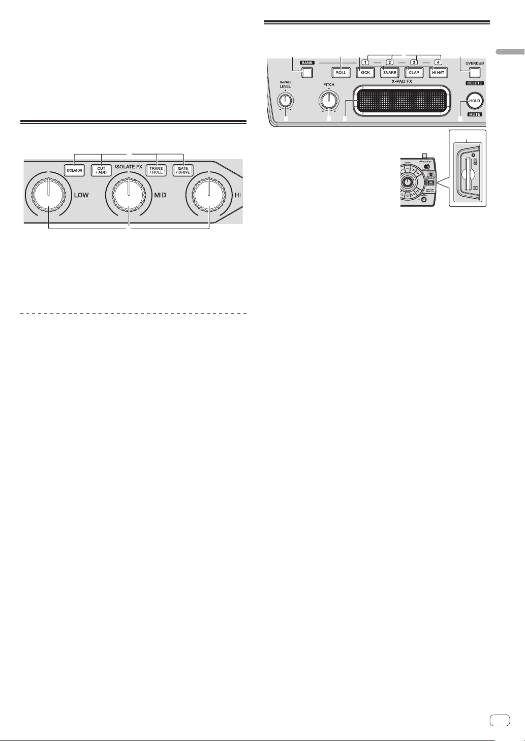
X-PAD FX section
21 5
34
987
Operation
6
a
2
1 ISOLATE FX button
These turn the ISOLATE FX effects on and off.
2 LOW, MID, and HI controls
These adjust the strength of the low, mid and high frequencies of the
selected ISOLATE FX effect.
Using the ISOLATE FX function
1 Press one of the [ISOLATE FX] buttons.
Select the ISOLATE FX effect type.
The button that was pressed flashes.
! For details on the types of effects, see Types of ISOLATE FX effects on
page 17.
! When the selected [ISOLATE FX] button is pressed again, the effect
turns off.
2 Turn the [LOW], [MID] or [HI] control.
The selected effect is applied to the sound selected in the FX SOURCE
section.
— The strength of the effect enhancing the sound increases as the
control is turned clockwise from the center. The strength of the
effect is maximum when the control is turned fully clockwise.
— The strength of the effect diminishing the sound increases as
the control is turned counterclockwise from the center. The
strength of the effect is maximum when the control is turned fully
counterclockwise.
1 BANK button
Use this to load sampled sound sources from SD memory cards.
2 ROLL button
Use this to sample the sound input to this unit and play it as a loop.
3 X-PAD FX buttons
One of this unit’s internal sound sources or one of the sampled
sound sources loaded from SD memory cards is selected and output. When a button is pressed, the sound is produced immediately
(“one-shot sound”).
4 BANK indicator
When loading sampled sound sources from SD memory cards, the
numbers of the loadable BANKs light.
5 OVERDUB (DELETE) button
This turns the OVERDUB function on and off.
When the OVERDUB function is on, this button is used to delete
sounds.
6 HOLD (MUTE) button
Press this to hold the X-PAD FX effect.
When the OVERDUB function is on, this button is used to mute
sounds.
7 X-PAD
Use this to adjust the X-PAD FX effect.
8 PITCH control
Use this to adjust the pitch of this unit’s internal sound sources,
sampled sound sources loaded from SD memory cards or sounds
being played in a loop.
9 X-PAD LEVEL control
Use this to adjust the audio level of this unit’s internal sound sources
or sampled sound sources loaded from SD memory cards.
When the [ROLL] button has been pressed, this control adjusts the
balance of the volume between the audio level of the currently playing track and the sampled sound.
a SD memory card insertion slot
Load SD memory cards here.
! Be sure to load SD memory cards in the proper front/back
direction.
! Do not forcibly insert or remove SD memory cards. Doing so
could damage the SD memory card or this unit.
! Do not insert any objects other than SD memory cards into
the SD memory card insertion slot. Inserting coins or other
metal objects could damage the internal circuitry, resulting in
malfunction.
! Only SD memory cards or SDHC memory cards conforming to
SD standards can be used on this unit.
En
13
Page 14

Using the X-PAD FX function
1 Press one of the [X-PAD FX] buttons.
One of this unit’s internal sound sources or one of the sampled sound
sources loaded from SD memory cards is selected and output. When a
button is pressed, the sound is produced immediately.
The pressed button lights.
! Internal sound sources are preset at the [KICK], [SNARE], [CLAP]
and [HI HAT] buttons, respectively.
! To select a sampled sound source stored on an SD memory card,
press the [X-PAD FX] button while pressing the [BANK] button.
2 Touch the [X-PAD].
This turns the effect on.
The effect changes according to the position on the [X-PAD] that is
touched.
! The effect turns off when you release your finger from the [X-PAD].
Sampling the currently playing sound
and using the X-PAD FX function
1 Press the [ROLL] button.
The [ROLL] button lights.
2 Touch the [X-PAD].
The sound at the time the [X-PAD] is touched is sampled and loop playback starts.
The number of beats sampled depends on the position on the [X-PAD]
that is touched.
1/81/4 1/21/1 2/1
! The effect turns off when you release your finger from the [X-PAD].
Using the hold function
Press the [HOLD (MUTE)] button.
When the hold mode is turned on, the X-PAD FX effect applied directly
before your finger was released from the [X-PAD] is held.
! Press the [HOLD (MUTE)] button again to turn the hold mode off.
Using the BANK function
When one of the [X-PAD FX] buttons ([KICK], [SNARE], [CLAP] or
[HI HAT]) is pressed while pressing the [BANK] button, the [BANK1],
[BANK2], [BANK3] or [BANK4] sampled sound sources are loaded
into the corresponding [X-PAD FX] button from the SD memory card
inserted into the SD memory card slot of this unit.
! When loading sampled sound sources from SD memory cards into
the [X-PAD FX] section, first use remixbox to store the sampled
sound sources on the SD memory card. For details, see the remixbox’s operating instructions.
1 Insert the SD memory card on which the sampled
sound sources are stored into the SD memory card slot
of this unit.
2 Press the [BANK] button to check which BANK can be
loaded.
When the [BANK] button is pressed, the [BANK] indicators flash for the
BANKs at which sampled sound sources can be loaded.
3 Press one of the [X-PAD FX] buttons ([KICK], [SNARE],
[CLAP] or [HI HAT]) while pressing the [BANK] button.
The sampled sound sources stored on the SD memory card are loaded
into [SLOT1] to [SLOT4] for the selected BANK.
[KICK]
button
[BANK] button + [KICK] button
[BANK] button + [SNARE]
button
[BANK] button + [CLAP]
button
[BANK] button + [HI HAT]
button
! The maximum number of sampled sound sources that can be loaded
is 4BANK x 4SLOT.
! The maximum length of the sampled sounds that can be set in the
BANK (the total for the 4SLOT) is 16 seconds.
! 48 kHz/24-bit or 48 kHz/16-bit WAV files are supported as sound
sources.
! When a lit [X-PAD FX] button is pressed while again pressing the
[BANK] button, this unit’s internal sound source is selected and
produced.
BANK1
SLOT1
BANK2
SLOT1
BANK3
SLOT1
BANK4
SLOT1
[SNARE]
button
BANK1
SLOT2
BANK2
SLOT2
BANK3
SLOT2
BANK4
SLOT2
[CLAP]
button
BANK1
SLOT3
BANK2
SLOT3
BANK3
SLOT3
BANK4
SLOT3
[HI HAT]
button
BANK1
SLOT4
BANK2
SLOT4
BANK3
SLOT4
BANK4
SLOT4
Using the OVERDUB function
Recording sounds and playing them
This function records four beats of the sounds stored at the [X-PAD FX]
buttons and plays the sounds in a loop.
1 Press the [OVERDUB (DELETE)] button.
The OVERDUB function turns on.
The standby mode is set until one of the [X-PAD FX] buttons is operated.
2 Press one of the [X-PAD FX] buttons.
When one of the [X-PAD FX] buttons is pressed, recording starts and a
4-beat loop starts playing.
! The sound of an [X-PAD FX] button can be added by pressing that
button during loop playback.
! When the [OVERDUB (DELETE)] button is pressed again, the
OVERDUB function turns off and playback and recording stop. The
recorded sound is deleted.
Muting recorded sounds
Press one of the [X-PAD FX] buttons while pressing the
[HOLD (MUTE)] button.
The sound of the [X-PAD FX] button that was pressed is muted from the
recorded sound.
! When the muted [X-PAD FX] button is pressed again while pressing
the [HOLD (MUTE)] button, the mute mode is canceled.
Deleting recorded sounds
Press one of the [X-PAD FX] buttons while pressing the
[OVERDUB (DELETE)] button.
The sound of the [X-PAD FX] button that was pressed is deleted from the
recorded sound.
! Deleted sounds cannot be retrieved.
14
En
Page 15

RELEASE FX section
1
2
3
1 RELEASE FX selector switch
This switches the type of RELEASE FX effect.
2 RELEASE FX lever
Use this to adjust the RELEASE FX effect.
3 RELEASE FX indicator
This lights when the effect is turned on. It lights according to the
position of the [RELEASE FX] lever.
Using the RELEASE FX function
1 Switch the [RELEASE FX] selector switch.
Select the RELEASE FX effect.
! For details on the types of effects, see Types of RELEASE FX effects on
page 18.
2 Move the [RELEASE FX] lever towards you.
This turns the effect on.
The selected effect is applied to the sound selected in the FX SOURCE
section.
! The effect changes according to the position of the lever.
! When the lever is moved back to its original position, the effect turns
off. Any SCENE FX, ISOLATE FX or X-PAD FX effects that were on
before are also turned off.
FX SOURCE section
1
2
FX SETTING section
Operation
1
1 SETTING selector switch
This switches this unit’s effect parameter data between the
[DEFAULT] and [USER] modes.
— [DEFAULT] mode: This unit can be used with the default param-
eter data set upon shipment from the factory.
— [USER] mode: Parameter data created using remixbox can be
loaded into this unit and used.
What you can do using remixbox
By using the “remixbox” application included with this unit, you can
change the settings shown below.
! Effect parameters: The parameters of the different effects can be
customized.
! Types of effects: The effect assigned to the [ROLL] in the X-PAD FX
section can be changed to a different effect.
! Button sensitivity: The sensitivity of the [SCENE FX] and [ISOLATE FX]
buttons can be adjusted.
! Management of sampled sound sources: Sampled sound sources
loadable into this unit can be saved and managed.
For details, refer to the remixbox’ help menu.
For instructions on installing remixbox, see Using remixbox on page 20.
Using this unit in the USER mode
! Create the customized parameter data beforehand using remixbox.
! Upon shipment from the factory, the same parameter data as for the
[DEFAULT] mode is set for the [USER] mode.
Writing the customized parameter data from
remixbox into this unit
1 Connect the computer on which remixbox is installed
to this unit by USB cable.
2 Send the customized parameter data from remixbox
to this unit.
3 Slide the [SETTING] selector switch to the [USER]
position.
1 INPUT button
The sound input to this unit’s [INPUT] terminals is routed to this
unit’s SCENE FX, ISOLATE FX and RELEASE FX sections.
2 X-PAD button
The sound output from the X-PAD FX section is routed to this unit’s
SCENE FX, ISOLATE FX and RELEASE FX sections.
Switching the audio signal path
Switch whether or not to route the sound input to this unit and the sound
generated internally to this unit’s SCENE FX, ISOLATE FX and RELEASE
FX sections.
Press the [INPUT] or [X-PAD] button.
The selected audio signal is input to this unit’s SCENE FX, ISOLATE FX
and RELEASE FX sections.
! It is also possible to select the [INPUT] and [X-PAD] button
simultaneously.
! The [NOISE] effect in the SCENE FX section is applied regardless of
the status of the [INPUT] and [X-PAD] buttons.
Loading customized parameter data stored on
an SD memory card
1 Store the customized parameter data on the SD
memory card using remixbox.
2 Insert the SD memory card used in step 1 into this
unit’s SD memory card slot.
3 Slide the [SETTING] selector switch to the [USER]
position.
! Customized parameter data stored on an SD memory card is
reflected on this unit simply by inserting that SD memory card into
this unit.
En
15
Page 16

Types of effects
Input sound turned off
Input sound turned off
Direct sound
Types of SCENE FX effects
BPF ECHO
This function superimposes the input sound that has passed through the
band pass filter onto the original input sound and passes this through
the echo circuit before outputting the sound.
The echo is output several times according to the multiplying factor of
the input sound’s beat, with the delay sound gradually attenuating.
Input sound that has passed
through the band pass filter
Input sound
SCENE FX
control
SCENE FX control Sets the band pass filter’s cutoff frequency.
SUB PARAMETER 1
control
SUB PARAMETER 2
control
Sets the echo sound’s delay time.
Applies a modulation effect to the output.
ECHO
The echo is output several times according to the multiplying factor of
the input sound’s beat, with the delay sound gradually attenuating.
1 beat
SCENE FX control
SUB PARAMETER 1
control
SUB PARAMETER 2
control
Use this to set the balance between the original sound
and the echo sound.
Sets the echo sound’s delay time.
Sets the filter’s cut-off frequency.
NOISE
This function passes white noise generated internally through the band
pass filter and echo before outputting it.
SCENE FX
control
SCENE FX control
SUB PARAMETER 1
control
SUB PARAMETER 2
control
Sets the cutoff frequency of the filter through which the
white noise passes.
Sets the volume of the white noise.
Applies a modulation effect to the white noise.
Frequency
Fade-out
Time
Frequency
SPIRAL UP
This function adds a reverberation effect to the input sound.
When the delay time is changed, the pitch changes simultaneously.
Fade-out
1 beat
SCENE FX control Sets the SPIRAL’s delay time.
SUB PARAMETER 1
control
SUB PARAMETER 2
control
Sets the echo sound’s delay time.
Sets the amount of pitch shifting by which the pitch is
raised.
Time
REVERB UP
This function adds a reverberation effect to the input sound.
Level
SCENE FX control Use this to set the degree of the reverb effect.
SUB PARAMETER 1
control
SUB PARAMETER 2
control
Early reflected sound
Reverberations
Time
Use this to set the degree of the reverb effect.
Sets the cutoff frequency of the high pass filter.
HPF ECHO
This function passes the input sound through the high pass filter and
echo before outputting it.
The echo is output several times according to the multiplying factor of
the input sound’s beat, with the delay sound gradually attenuating.
Frequency
SCENE FX control Sets the cutoff frequency of the high pass filter.
SUB PARAMETER 1
control
SUB PARAMETER 2
control
Sets the echo sound’s delay time.
Applies a modulation effect to the output.
LPF ECHO
This function passes the input sound through the low pass filter and
echo before outputting it.
The echo is output several times according to the multiplying factor of
the input sound’s beat, with the delay sound gradually attenuating.
16
En
Page 17

Frequency
Input sound turned off
1 beat
SCENE FX control Sets the cutoff frequency of the low pass filter.
SUB PARAMETER 1
control
SUB PARAMETER 2
control
Sets the echo sound’s delay time.
Applies a modulation effect to the output.
CRUSH ECHO
This function creates a sound as if the input sound were crushed and
passes it through the filter and echo before outputting it.
The echo is output several times according to the multiplying factor of
the input sound’s beat, with the delay sound gradually attenuating.
SCENE FX
control
Cycle
Time
Types of ISOLATE FX effects
ISOLATOR
This function allows you to split the input sound into three bands – low,
mid, and high – and adjust the audio level for the respective bands.
LOW control Adjusts the audio level of the low frequencies.
MID control Adjusts the audio level of the mid frequencies.
HI control Adjusts the audio level of the high frequencies.
CUT/ADD
CUT: When turned counterclockwise
This function allows you to adjust the audio level of the bass drum
detected in the input sound and the manual filter’s cutoff frequency.
LOW control
MID control
HI control
Adjusts the audio level of the bass drum detected in the
input sound.
Applies the sound other than the bass drum detected in
the input sound to the high pass filter.
Applies the sound other than the bass drum detected in
the input sound to the low pass filter.
Types of effects
SCENE FX control Sets the degree by which the input sound is crushed.
SUB PARAMETER 1
control
SUB PARAMETER 2
control
Sets the echo sound’s delay time.
Applies a modulation effect to the output.
SPIRAL DOWN
This function adds a reverberation effect to the input sound.
When the delay time is changed, the pitch changes simultaneously.
Fade-out
Time
SCENE FX control Sets the SPIRAL’s delay time.
SUB PARAMETER 1
control
SUB PARAMETER 2
control
Sets the echo sound’s delay time.
Sets the amount of pitch shifting by which the pitch is
decreased.
REVERB DOWN
This function adds a reverberation effect to the input sound.
Direct sound
Level
Early reflected sound
Reverberations
Time
Bass drum
Bass drum
Bass drum
Bass drum
Bass drum
Bass drum
Frequency
ADD: When turned clockwise
This function lets you apply a 1/8-beat delay sound according to the
multiplying factor of the input sound’s beat.
LOW control Adjusts the audio level of the low frequency delay sound.
MID control Adjusts the audio level of the mid frequency delay sound.
HI control
Adjusts the audio level of the high frequency delay
sound.
1/1 beat
Time
SCENE FX control Use this to set the degree of the reverb effect.
SUB PARAMETER 1
control
SUB PARAMETER 2
control
Use this to set the degree of the reverb effect.
Sets the cutoff frequency of the low pass filter.
1/4 beat
1/8 beat
1/2 beat
En
17
Page 18

TRANS/ROLL
TRANS: When turned counterclockwise
This function cuts the input sound according to the multiplying factor of
the beat set at the position of the control.
LOW control
MID control
HI control
1/2 beat
Adjusts the amount by which the low frequency sound
is cut.
Adjusts the amount by which the mid frequency sound
is cut.
Adjusts the amount by which the high frequency sound
is cut.
1/1 beat
Time
Level
Threshold
Threshold
Threshold
DRIVE: When turned clockwise
This function distorts the input sound.
LOW control
MID control
HI control
Adjusts the amount by which the low frequency sound
is distorted.
Adjusts the amount by which the mid frequency sound
is distorted.
Adjusts the amount by which the high frequency sound
is distorted.
Time
1/4 beat
ROLL: When turned clockwise
This function records the input sound starting from the point when the
[LOW], [MID] or [HI] control is turned and outputs the recorded sound
repeatedly according to the multiplying factor of the beat set at the position of the control.
LOW control
MID control
HI control
Original
1/1 roll
1/2 roll
Adjusts the cycle at which the low frequency sound is
output repeatedly.
Adjusts the cycle at which the mid frequency sound is
output repeatedly.
Adjusts the cycle at which the high frequency sound is
output repeatedly.
Effect turned on
Repeated
Repeated
GATE/DRIVE
GATE: When turned counterclockwise
This function outputs the portion of the input sound that has a level
higher than the threshold level, cutting the portion of the input sound
with a lower level.
LOW control Adjusts the threshold level of the low frequency sound.
MID control Adjusts the threshold level of the mid frequency sound.
HI control Adjusts the threshold level of the high frequency sound.
Cycle
Time
Types of X-PAD FX effects
Records the input sound starting from the point when
ROLL
KICK
SNARE
CLAP
HI HAT
SAMPLER
the [X-PAD] is touched and outputs the recorded sound
repeatedly according to the multiplying factor of the beat
set with the [X-PAD].
Outputs this unit’s internal “KICK” sound source.
Outputs this unit’s internal “SNARE” sound source.
Outputs this unit’s internal “CLAP” sound source.
Outputs this unit’s internal “HI HAT” sound source.
Outputs the sampled sound recorded on an SD memory
card.
Types of RELEASE FX effects
VINYL BRAKE
ECHO
BACK SPIN
Achieves the effect of the input sound’s playing speed
gradually slowing and finally stopping.
The echo is output several times in beat with the input
sound, with the delay sound gradually attenuating.
Achieves the effect of the currently playing input sound
being played in reverse at high speed.
18
En
Page 19

Using the included software
Software end user license
agreement
This Software End User License Agreement (“Agreement”) is between
you (both the individual installing the Program and any single legal
entity for which the individual is acting) (“You” or “Your”) and PIONEER
CORPORATION (“Pioneer”).
TAKING ANY STEP TO SET UP OR INSTALL THE PROGRAM MEANS
THAT YOU ACCEPT ALL OF THE TERMS OF THIS LICENSE AGREEMENT.
PERMISSION TO DOWNLOAD AND/OR USE THE PROGRAM IS
EXPRESSLY CONDITIONED ON YOUR FOLLOWING THESE TERMS.
WRITTEN OR ELECTRONIC APPROVAL IS NOT REQUIRED TO MAKE
THIS AGREEMENT VALID AND ENFORCEABLE. IF YOU DO NOT
AGREE TO ALL OF THE TERMS OF THIS AGREEMENT, YOU ARE NOT
AUTHORIZED TO USE THE PROGRAM AND MUST STOP INSTALLING IT
OR UNINSTALL IT, AS APPLICABLE.
1 Definitions
1 “Documentation” means written documentation, specifications
and help content made generally available by Pioneer to aid in
installing and using the Program.
2 “Program” means all or any part of Pioneer’s software licensed to
You by Pioneer under this Agreement.
2 Program license
1 Limited License. Subject to this Agreement’s restrictions,
Pioneer grants to You a limited, non-exclusive, nontransferable,
license (without the right to sublicense):
a To install a single copy of the Program on the hard disk
drive of Your computer, to use the Program only for Your
personal purpose complying with this Agreement and the
Documentation (“Authorized Use”);
b To use the Documentation in support of Your Authorized Use;
and
c To make one copy of the Program solely for backup pur-
poses, provided that all titles and trademark, copyright and
restricted rights notices are reproduced on the copy.
2 Restrictions. You will not copy or use the Program or
Documentation except as expressly permitted by this Agreement.
You will not transfer, sublicense, rent, lease or lend the Program,
or use it for third-party training, commercial time-sharing or
service bureau use. You will not Yourself or through any third
party modify, reverse engineer, disassemble or decompile the
Program, except to the extent expressly permitted by applicable
law, and then only after You have notified Pioneer in writing of
Your intended activities. You will not use the Program on multiple
processors without Pioneer’s prior written consent.
3 Ownership. Pioneer or its licensor retains all right, title and
interest in and to all patent, copyright, trademark, trade secret
and other intellectual property rights in the Program and
Documentation, and any derivative works thereof. You do not
acquire any other rights, express or implied, beyond the limited
license set forth in this Agreement.
4 No Support. Pioneer has no obligation to provide support,
maintenance, upgrades, modifications or new releases for the
Program or Documentation under this Agreement.
3 Warranty disclaimer
THE PROGRAM AND DOCUMENTATION ARE PROVIDED “AS IS”
WITHOUT ANY REPRESENTATIONS OR WARRANTIES, AND YOU
AGREE TO USE THEM AT YOUR SOLE RISK. TO THE FULLEST EXTENT
PERMISSIBLE BY LAW, PIONEER EXPRESSLY DISCLAIMS ALL
WARRANTIES OF ANY KIND WITH RESPECT TO THE PROGRAM AND
DOCUMENTATION, WHETHER EXPRESS, IMPLIED, STATUTORY,
OR ARISING OUT OF COURSE OF PERFORMANCE, COURSE OF
DEALING OR USAGE OF TRADE, INCLUDING ANY WARRANTIES
OF MERCHANTABILITY, FITNESS FOR A PARTICULAR PURPOSE,
SATISFACTORY QUALITY, ACCURACY, TITLE OR NON-INFRINGEMENT.
4 Damages and remedies for breach
You agree that any breach of this Agreement’s restrictions would cause
Pioneer irreparable harm for which money damages alone would be
inadequate. In addition to damages and any other remedies to which
Pioneer may be entitled, You agree that Pioneer may seek injunctive
relief to prevent the actual, threatened or continued breach of this
Agreement.
5 Termination
Pioneer may terminate this Agreement at any time upon Your breach of
any provision. If this Agreement is terminated, You will stop using the
Program, permanently delete it from the computer where it resides, and
destroy all copies of the Program and Documentation in Your possession, confirming to Pioneer in writing that You have done so. Sections
2.2, 2.3, 2.4, 3, 4, 5 and 6 will continue in effect after this Agreement’s
termination.
6 General terms
1 Limitation of Liability. In no event will Pioneer or its subsidiaries
be liable in connection with this Agreement or its subject matter,
under any theory of liability, for any indirect, incidental, special,
consequential or punitive damages, or damages for lost profits,
revenue, business, savings, data, use, or cost of substitute procurement, even if advised of the possibility of such damages or if
such damages are foreseeable. In no event will Pioneer’s liability
for all damages exceed the amounts actually paid by You to
Pioneer or its subsidiaries for the Program. The parties acknowledge that the liability limits and risk allocation in this Agreement
are reflected in the Program price and are essential elements of
the bargain between the parties, without which Pioneer would
not have provided the Program or entered into this Agreement.
2 The limitations or exclusions of warranties and liability contained
in this Agreement do not affect or prejudice Your statutory rights
as consumer and shall apply to You only to the extent such limitations or exclusions are permitted under the laws of the jurisdiction where You are located.
3 Severability and Waiver. If any provision of this Agreement is held
to be illegal, invalid or otherwise unenforceable, that provision
will be enforced to the extent possible or, if incapable of enforcement, deemed to be severed and deleted from this Agreement,
and the remainder will continue in full force and effect. The
waiver by either party of any default or breach of this Agreement
will not waive any other or subsequent default or breach.
4 No Assignment. You may not assign, sell, transfer, delegate or
otherwise dispose of this Agreement or any rights or obligations
under it, whether voluntarily or involuntarily, by operation of law
or otherwise, without Pioneer’s prior written consent. Any purported assignment, transfer or delegation by You will be null and
void. Subject to the foregoing, this Agreement will be binding
upon and will inure to the benefit of the parties and their respective successors and assigns.
5 Entire Agreement. This Agreement constitutes the entire agree-
ment between the parties and supersedes all prior or contemporaneous agreements or representations, whether written or
oral, concerning its subject matter. This Agreement may not be
modified or amended without Pioneer’s prior and express written
consent, and no other act, document, usage or custom will be
deemed to amend or modify this Agreement.
6 You agree that this Agreement shall be governed and construed
by and under the laws of Japan.
Using the included software
En
19
Page 20

Using remixbox
When the remixbox application installed on a computer is used, the settings of the parameters of this unit’s effects can be customized to your
liking. The remixbox can also be used to load sampled sound sources
into the X-PAD FX section.
Use remixbox on the computer to prepare the effects’ customized
parameter data and the sampled sound sources ahead of time. The customized parameter data and the sampled sound sources can be stored
on an SD memory card and loaded into this unit. It can also be loaded
directly onto this unit when this unit and computer are connected by
USB cable.
Cautions on Installation
! If installation of remixbox is interrupted before it is completed, follow
the procedure below to install again from the beginning.
! Read the “Software end user license agreement” carefully before
installing remixbox.
! If there are any programs running on the computer, quit them before
installing remixbox.
! remixbox is supported on the following operating systems:
Supported operating systems
Windows
Intel
Mac
1 A hotfix program provided by Microsoft must be installed. The customer is
responsible for installation of the hotfix program.
1 Access the Microsoft support site (http://support.microsoft.com/).
2 At the site’s search window, search for document number “2182039” and
download the hotfix.
! Because Microsoft has stopped providing support for the operating systems
below, Pioneer offers no guarantees when using these operating systems.
— Windows Vista
earlier)
— Windows® XP Home Edition/Professional (SP2 and earlier)
Installing remixbox
Installation procedure (Windows)
Read Cautions on Installation carefully before installing remixbox.
! Authorization of the computer’s administrator is required to install
and uninstall remixbox.
Log on as the user which was set as the computer’s administrator
before installing.
1 Insert the remixbox CD-ROM into the computer’s CD
drive.
The CD-ROM menu is displayed.
®
Windows
7 Home Premium/Professional/
Ultimate
Windows Vista
Home Premium/Business/Ultimate (SP2
or later)
Windows
(SP3 or later)
Mac OS X 10.7
Mac OS X 10.6
Mac OS X 10.5 32-bit version
®
Home Basic/
®
XP Home Edition/Professional
®
Home Basic/Home Premium/Business/Ultimate (SP1 and
32-bit version
64-bit version
32-bit version
64-bit version
32-bit version
64-bit version
32-bit version
64-bit version
32-bit version
64-bit version
1
1
1
1
3
1
3
1
1
1
1
1
! If the CD-ROM menu does not appear when the CD-ROM is inserted,
open the CD drive from [Computer (or My Computer)] in the [Start]
menu, then double-click the [CD_menu.exe] icon.
2 When the CD-ROM’s menu is displayed, select
[remixbox: Install remixbox], then click [Start].
! To close the CD-ROM menu, click [Quit].
3 When the language selection screen appears, select
[English] and click [OK].
! You can select the one you desire from multiple languages as long
as the language is supported by the system environment of your
computer.
4 When the license agreement screen appears, read the
Software end user license agreement carefully. If you
agree to the Software end user license agreement, click
[Agree].
! If you do not consent to the provisions of the Software end user
license agreement, click [Cancel] and stop installation.
5 Install remixbox by following the instructions on the
screen.
! Click [Cancel] to cancel installation after it has started.
Installation procedure (Mac OS X)
Read Cautions on Installation carefully before installing remixbox.
! Authorization of the computer’s administrator is required to install
and uninstall remixbox.
Log on as the user which was set as the computer’s administrator
before installing.
1 Insert the remixbox CD-ROM into the computer’s CD
drive, and then double-click the [CD_menu.app] icon
once it is displayed in a window.
! If the window containing the [CD_menu.app] icon is not displayed
when the CD-ROM is inserted, use Finder to open the CD drive
manually and double-click the [CD_menu.app] icon.
2 When the CD-ROM’s menu is displayed, select
[remixbox: Install remixbox], then click [Start].
! To close the CD-ROM menu, click [Quit].
3 When the license agreement screen appears, select
[English], read the Software end user license agreement
carefully, then click [Continue].
! You can select the one you desire from multiple languages as long
as the language is supported by the system environment of your
computer.
4 If you agree to the Software end user license
agreement, click [Agree].
! If you do not consent to the provisions of the Software end user
license agreement, click [Disagree] and stop installation.
5 Install remixbox by following the instructions on the
screen.
20
En
Page 21

Launching remixbox/Viewing the
Operating Instructions
Log on as the user which was set as the computer’s administrator before
using remixbox.
The operating instructions can be viewed by launching remixbox then
clicking [Manual] from the remixbox [Help] menu.
For Windows® 7, Windows Vista® and Windows®
XP
Click on the Windows [Start] menu button, then [All
Programs] > [Pioneer] > [remixbox 1.x.x] > [remixbox
1.x.x].
! The 1.x.x indicates the remixbox version.
For Mac OS X
Open the [Application] folder with Finder, then doubleclick [remixbox 1.x.x.app].
! The 1.x.x indicates the remixbox version.
Connecting this unit and computer
1 Slide the [ON, STANDBY] switch on the rear panel of
this unit to the [ON] position.
Turn on the power of this unit.
2 Connect this unit to your computer via a USB cable.
! This operation does not work with computers that do not support
USB 2.0.
! When using Windows XP, if another USB-MIDI device is connected
simultaneously to the computer, it may not operate properly or may
not be recognized. Only connect the computer and this unit.
! Connect this unit and the computer directly using the included USB
cable.
Using the included software
Checking the latest information on
the included software
For the latest information on the included software and supported operating systems, see the website below.
http://pioneerdj.com/support/
! Operation cannot be guaranteed when multiple units of this mixer
are connected to a single computer.
En
21
Page 22

Changing this unit’s settings
Changing the MIDI settings
The following buttons are used to change the MIDI settings:
— [TAP] button: Used as the Enter button.
— [AUTO] button: Used as the Cancel button.
— [NUDGE (+, –)] button: Used to select items.
1 Turn on this unit’s power while pressing the
[QUANTIZE] button.
This unit starts up in the mode for changing the MIDI settings.
The setting items are displayed on the BPM display.
2 Press the [+] or [–] side of the [NUDGE (+, –)] button.
Select whether to change the MIDI channel or MIDI button type.
— If [CH] or numbers are displayed: MIDI channel changing mode
— If [btn] or letters are displayed: MIDI button type changing mode
3 Press the [TAP] button.
Switch to the mode for changing the MIDI channel or the one for changing the MIDI button type.
The MIDI channel number or MIDI button type flashes on the BPM
display.
4 Press the [+] or [–] side of the [NUDGE (+, –)] button.
Select and change the MIDI channel or MIDI button type. The values
below can be selected for each of these.
— MIDI channel: [1] to [16]
— MIDI button type: [tGL (toggle)] or [trG (trigger)]
5 Press the [TAP] button.
The selected setting is stored.
The stored setting flashes rapidly on the BPM display.
! When this unit’s power is turned off, the mode for changing the MIDI
settings is quit.
! The settings on this unit upon shipment from the factory are as
follows:
— MIDI channel: [1]
— MIDI button type: [tGL (toggle)]
Using the update function
! Do not turn off this unit’s power during the updating procedure.
1 Turn on this unit’s power while pressing the
[HOLD (MUTE)] and [TAP] buttons.
This unit starts up in the updating mode.
The current firmware version number is displayed on the BPM display,
and the right edge of the [OUTPUT] level indicator flashes.
2 Insert the SD memory card on which the update file is
stored into the SD memory card slot of this unit.
Updating starts.
The [OUTPUT] level indicator lights to indicate the progress of updating.
Once all segments of the [OUTPUT] level indicator are lit, updating is
completed.
! If an error occurs during updating, the type of error is indicated by
the BPM display and the number of segments of the [INPUT] level
indicator that are lit.
BPM
display
E00
E10
E20
E30
E40
E50
E60
E70
E80
E90
3-digit number
Lit segments of the
[INPUT] level indicator
Type of error
Updating error
Updating error
Updating error
Updating file not detected
Updating file corrupt
SD memory card reading error
Memory clearing error
Memory writing error
Memory verification error
SD memory card error
Updating completed normally
Temporarily changing the MIDI channel
for the RMX-1000 Plug-in
Even when this unit is not in the mode for changing the MIDI settings, it
is possible to temporarily change the MIDI channel.
1 Press the [+] or [–] side of the [NUDGE (+, –)] button
while pressing the [BANK] button.
The MIDI channel number appears on the BPM display.
2 Release the [BANK] button.
! The MIDI channel changed in this way is reflected on this unit until
the power is turned off.
En
22
Page 23

MIDI assignment map
! “CC” is the abbreviation of “control change”. A control change is a type of MIDI signal used to transmit various types of control information, such as
timbre, volume, etc.
! “Note” is a MIDI term used when pressing or releasing notes on a piano or other keyboard.
On this unit, values from 0 to 127 are output as CCs when controls or the [X-PAD] are operated. Also, when buttons or switches are operated, val-
ues from 0 to 127 are output as Notes.
Category SW Name SW Type MIDI Messages
LEVEL OUTPUT LEVEL control VR CC 000 — 0-127
QUANTIZE button BTN Note 000
AUTO button BTN Note 001
BPM/QUANTIZE
FX SOURCE
ISOLATE FX
X-PAD FX
SCENE FX
RELEASE FX
FX SETTING
TAP button BTN Note 002 Trigger only OFF=0, ON=127
NUDGE(–) button BTN Note 003 Trigger only OFF=0, ON=127
NUDGE(+) button BTN Note 004 Trigger only OFF=0, ON=127
INPUT button BTN Note 005
X-PAD button BTN Note 006
LOW control VR CC 001 — 0-127
MID control VR CC 002 — 0-127
HI control VR CC 003 — 0-127
ISOLATOR button BTN Note 007
CUT/ADD button BTN Note 008
TRANS/ROLL button BTN Note 009
GATE/DRIVE button BTN Note 010
BANK button BTN Note 011 Trigger only OFF=0, ON=127
ROLL button BTN Note 012 Trigger only OFF=0, ON=127
KICK button BTN Note 013 Trigger only OFF=0, ON=127
SNARE button BTN Note 014 Trigger only OFF=0, ON=127
CLAP button BTN Note 015 Trigger only OFF=0, ON=127
HI HAT button BTN Note 016 Trigger only OFF=0, ON=127
OVERDUB (DELETE) button BTN Note 017 Toggle only OFF=0, ON=127
HOLD (MUTE) button BTN Note 018 Toggle only OFF=0, ON=127
X-PAD LEVEL control VR CC 004 — 0-127
PITCH control VR CC 005 — 0-127
X-PAD (position) VR CC 006 —
X-PAD (touch) BTN Note 019 Trigger only
SCENE FX control VR CC 007 — 0-127
SUB PARAMETER 1 control VR CC 008 — 0-127
SUB PARAMETER 2 control VR CC 009 — 0-127
BPF ECHO button BTN Note 020
ECHO button BTN Note 021
NOISE button BTN Note 022
SPIRAL UP button BTN Note 023
REVERB UP button BTN Note 024
HPF ECHO button BTN Note 025
LPF ECHO button BTN Note 026
CRUSH ECHO button BTN Note 027
SPIRAL DOWN button BTN Note 028
REVERB DOWN button BTN Note 029
RELEASE FX selector switch 1 (VINYL
BRAKE)
RELEASE FX selector switch 2 (ECHO) SW Note 031 Trigger only
RELEASE FX selector switch 3 (BACK
SPIN)
RELEASE FX lever VR CC 010 — 0-127
SETTING selector switch 1 (DEFAULT) SW Note 033 Trigger only
SETTING selector switch 2 (USER) SW Note 034 Trigger only
SW Note 030 Trigger only
SW Note 032 Trigger only
MIDI button type
Trigger/Toggle
1
1
1
1
1
1
1
1
1
1
1
1
1
1
1
1
1
1
1
1
1
1
1
Notes
OFF=0, ON=127
OFF=0, ON=127
OFF=0, ON=127
OFF=0, ON=127
OFF=0, ON=127
OFF=0, ON=127
OFF=0, ON=127
OFF=0, ON=127
0-127
Sends the [X-PAD]
position information.
OFF (when not touched)
= 0, ON (when
touched) =127
OFF=0, ON=127
OFF=0, ON=127
OFF=0, ON=127
OFF=0, ON=127
OFF=0, ON=127
OFF=0, ON=127
OFF=0, ON=127
OFF=0, ON=127
OFF=0, ON=127
OFF=0, ON=127
OFF=0, ON=127
OFF=0, ON=127
OFF=0, ON=127
OFF=0, ON=127
OFF=0, ON=127
MIDI assignment map
En
23
Page 24

Category SW Name SW Type MIDI Messages
OVERDUB (DELETE) button + ROLL
button
OVERDUB (DELETE) button + KICK
button
OVERDUB (DELETE) button + SNARE
button
OVERDUB (DELETE) button + CLAP
button
OVERDUB (DELETE) button + HI HAT
Plug-in control
1 When the [RELEASE FX] selector switch and the [SETTING] selector switch are slid, “OFF” is sent from the switch that has not yet been switched, “ON” from the switch that
has been switched.
button
OVERDUB (DELETE) button + X-PAD
(touch)
HOLD (MUTE) button + ROLL button BTN Note 041 Trigger only OFF=0, ON=127
HOLD (MUTE) button + KICK button BTN Note 042 Trigger only OFF=0, ON=127
HOLD (MUTE) button + SNARE button BTN Note 043 Trigger only OFF=0, ON=127
HOLD (MUTE) button + CLAP button BTN Note 044 Trigger only OFF=0, ON=127
HOLD (MUTE) button + HI HAT button BTN Note 045 Trigger only OFF=0, ON=127
HOLD (MUTE) button + X-PAD (touch) BTN Note 046 Trigger only OFF=0, ON=127
BTN Note 035 Trigger only OFF=0, ON=127
BTN Note 036 Trigger only OFF=0, ON=127
BTN Note 037 Trigger only OFF=0, ON=127
BTN Note 038 Trigger only OFF=0, ON=127
BTN Note 039 Trigger only OFF=0, ON=127
BTN Note 040 Trigger only OFF=0, ON=127
MIDI button type
Trigger/Toggle
Notes
24
En
Page 25

Additional information
Troubleshooting
! Incorrect operation is often mistaken for trouble or malfunction. If you think that there is something wrong with this component, check the points
below. Sometimes the trouble may lie in another component. Inspect the other components and electrical appliances being used. If the trouble
cannot be rectified after checking the items below, ask your nearest Pioneer authorized service center or your dealer to carry out repair work.
! The player may not operate properly due to static electricity or other external influences. In such cases, normal operation may be restored by
unplugging the power cord then plugging it back in.
Problem Check Remedy
The power is not turned on. Are the included power cord and AC adapter
No sound or small sound. Are the connection cables properly connected? Connect the connection cables properly. (page 7)
Distorted sound. Is the audio level output from the [OUTPUT]
Tempo (BPM) cannot be measured or
measurement value of tempo (BPM) is
implausible.
Value of the measured tempo (BPM)
differs from value recorded on CD, or
tempo (BPM) values displayed on DJ
player, DJ mixer, DJ software and this
unit differ.
This unit is not recognized after it has
been connected to a computer.
SD memory card is not recognized. Is the SD memory card properly inserted? Insert the SD memory card securely all the way in. (Page 13)
Much time is required to load data
from an SD memory card.
Effects are not applied. Is the [INPUT] or [X-PAD] button lit? Press the [INPUT] or [X-PAD] button. (Page 15)
ISOLATE FX effects are not applied. Is the [ISOLATE FX] control set to an appropriate
X-PAD FX effects are not applied. Is the [X-PAD LEVEL] control set to an appropriate
SCENE FX effects are not applied. Is the [SCENE FX] control set to an appropriate
MIDI sequencer does not synchronize. Is the MIDI sequencer’s sync mode set to Slave? Set the MIDI sequencer’s sync mode to Slave.
MIDI control does not work. Are the MIDI settings properly set? To operate DJ software with this unit, this unit’s MIDI messages must be
properly connected?
Is the [ON, STANDBY] switch for power supply
set to [ON]?
Are the terminals and plugs dirty? Clean the terminals and plugs before making connections.
Is the [CONNECTION] selector switch on the rear
panel of this unit properly set?
terminals appropriately set?
Is the audio level input to the [INPUT] terminals
appropriately set?
Is the audio input level too high or too low? Adjust the [INPUT LEVEL] control so that the [INPUT] level indicator lights up to
— The values may differ slightly due to the different ways in which the BPM is
Is the included USB cable properly connected? Connect this unit and computer directly, not via a USB hub.
Is the SD memory card one that is usable on this
unit?
Are there a large number of folders or files
recorded on the SD memory card?
Have you stored files other than setting files and
sampled data on the SD memory card?
position?
position?
position?
Does the MIDI sequencer you are using support
MIDI timing clocks?
Properly connect the included power cord to a power outlet.
Properly connect the power cord to the included AC adapter. (page 7)
Connect the included AC adapter’s DC plug properly to this unit.
Set the [ON, STANDBY] switch for power supply to [ON].
Switch the [CONNECTION] selector switch according to the connected device.
(page 11)
Adjust the [OUTPUT LEVEL] control so that the [OUTPUT] level indicator lights
up to about [0 dB] at the peak level. (Page 11)
Adjust the [INPUT LEVEL] control so that the [INPUT] level indicator lights up to
about [0 dB] at the peak level. (page 11)
about [0 dB] at the peak level. (page 11)
For some tracks, it may not be possible to measure the tempo (BPM). Use the
[TAP] button to input the tempo manually. (page 12)
measured.
SD memory cards have a front and back. Be sure to insert them in the proper
direction.
Only SD memory cards or SDHC memory cards can be used on this unit. Some
cards may not be usable.
When there are many folders or files, some time may be required for loading.
If the folder contains files other than setting files and sampled data, some time
will be required for loading. Do not put files other than setting files and sampled
data in the folder.
Turn the [ISOLATE FX] control clockwise or counterclockwise. (Page 13)
Turn the [X-PAD LEVEL] control clockwise. (Page 13)
Turn the [SCENE FX] control clockwise. (Page 12)
MIDI sequencers not supporting MIDI timing clocks cannot be synchronized.
assigned to the DJ software you are using. For instructions on assigning messages, see your DJ software’s operating instructions.
Additional information
En
25
Page 26

Block Diagram
About trademarks and registered
trademarks
! Pioneer is a registered trademark of PIONEER CORPORATION.
! Microsoft®, Windows Vista®, Windows® and Internet Explorer® are
either registered trademarks or trademarks of Microsoft Corporation
in the United States and/or other countries.
! Apple, Macintosh, Mac OS, Safari, iTunes, and Finder are trade-
marks of Apple Inc., registered in the U.S. and other countries.
! Intel and Pentium are trademarks of Intel Corporation in the U.S. and
other countries.
! VST is a trademark of Steinberg Media Technologies GmbH.
! The Audio Units logo is a trademark of Apple Inc.
The names of companies and products mentioned herein are the trademarks of their respective owners.
This product has been licensed for nonprofit use. This product has not
been licensed for commercial purposes (for profit-making use), such
as broadcasting (terrestrial, satellite, cable or other types of broadcasting), streaming on the Internet, Intranet (a corporate network) or other
types of networks or distributing of electronic information (online digital music distribution service). You need to acquire the corresponding
licenses for such uses. For details, see http://www.mp3licensing.com.
Cautions on copyrights
Recordings you have made are for your personal enjoyment and according to copyright laws may not be used without the consent of the copyright holder.
! Music recorded from CDs, etc., is protected by the copyright laws of
individual countries and by international treaties. It is the full responsibility of the person who has recorded the music to ensure that it is
used legally.
! When handling music downloaded from the Internet, etc., it is the
full responsibility of the person who has downloaded the music to
ensure that it is used in accordance with the contract concluded
with the download site.
Disclaimer
Please note that Pioneer will accept no responsibility whatsoever for
legality, morality or certainty of operation concerning use of the included
software by the customer. Depending on the operating environment of
the customer’s computer and the included software and combinations
with other software, problems may arise in the operation of the included
software.
Please note that Pioneer will accept no responsibility for loss of information registered by the customer using the included software. Please
make a separate note, etc., of contents you register.
Specifications
AC adapter
Power ............................................................ AC 100 V to 240 V, 50 Hz/60 Hz
Rated current ......................................................................................... 0.4 A
Rated output ................................................................................. DC 5 V, 2 A
General – Main Unit
Power consumption ............................................................................... 1.4 A
Main unit weight .......................................................................1.3 kg (2.9 lb)
Max. dimensions ......................... 334 mm (W) × 57 mm (H) × 157 mm (D)
(13.15 in. (W) × 2.24 in. (H) × 6.18 in. (D))
Tolerable operating temperature ......... +5 °C to +35 °C (+41 °F to +95 °F)
Tolerable operating humidity ...................... 5 % to 85 % (no condensation)
Audio Section
Sampling rate .......................................................................................48 kHz
A/D, D/A converter ...............................................................................24 bits
Frequency response.............................................................. 20 Hz to 20 kHz
S/N ratio (rated output)
When CONNECTION is set to "SEND/RETURN (–10 dB)" ......... 102 dB
When CONNECTION is set to "MASTER (+4 dB)" ........................ 98 dB
Total harmonic distortion ..................................................................0.005 %
Headroom .............................................................................................. 20 dB
Input level / Input impedance
When CONNECTION is set to "SEND/RETURN (–10 dB)"
........................................................................ –10 dBV/22 kW or greater
When CONNECTION is set to "MASTER (+4 dB)"
.........................................................................+4 dBu/22 kW or greater
Output level / Load impedance / Output impedance
When CONNECTION is set to "SEND/RETURN (–10 dB)"
.....................................................................–10 dBV/10 kW/1 kW or less
When CONNECTION is set to "MASTER (+4 dB)"
..................................................................... +4 dBu/10 kW/1 kW or less
Input / Output terminals
INPUT terminals
RCA pin jacks ....................................................................................1 set
Phone jack (Ø 6.3 mm) ..................................................................... 1 set
OUTPUT terminals
RCA pin jacks ....................................................................................1 set
Phone jack (Ø 6.3 mm) ..................................................................... 1 set
USB terminal
B type .................................................................................................1 set
— The specifications and design of this product are subject to
change without notice.
— The software screens used in these operating instructions are
from the development stage and may differ from the actual
screens.
26
En
Page 27

PIONEER ELECTRONICS (USA) INC.
WARRANTY VALID ONLY IN THE U.S.A. AND CANADA
WARRANTY
Pioneer Electronics (USA) Inc. (PUSA) warrants that products distributed by PUSA in the U.S.A. and Canada that fail to function properly under normal use due to a manufacturing
defect when installed and operated according to the owner’s manual enclosed with the unit will be repaired or replaced with a unit of comparable value, at the option of PUSA,
without charge to you for parts or actual repair work. Parts supplied under this warranty may be new or rebuilt at the option of PUSA.
THIS LIMITED WARRANTY APPLIES TO THE ORIGINAL OR ANY SUBSEQUENT OWNER OF THIS PIONEER PRODUCT DURING THE WARRANTY PERIOD PROVIDED THE
PRODUCT WAS PURCHASED FROM AN AUTHORIZED PIONEER DISTRIBUTOR/DEALER IN THE U.S.A. OR CANADA. YO U WILL BE REQUIRED TO PROVIDE A SALES
RECEIPT OR OTHER VALID PROOF OF PURCHASE SHOWING THE DATE OF ORIGINAL PURCHASE OR, IF RENTED, YOUR RENTAL CONTRACT SHOWING THE PLACE
AND DATE OF FIRST RENTAL. IN THE EVENT SERVICE IS REQUIRED, THE PRODUCT MUST BE DELIVERED WITHIN THE WARRANTY PERIOD, TRANSPORTATION
PREPAID, ONLY FROM WITHIN THE U.S.A. AS EXPLAINED IN THIS DOCUMENT. YO U WILL BE RESPONSIBLE FOR REMOVAL AND INSTALLATION OF THE PRODUCT .
PUSA WILL PAY TO RETURN THE REPAIRED OR REPLACEMENT PRODUCT TO YOU WITHIN THE U.S.A.
PRODUCT WARRANTY PERIOD
DJ Audio and Video ................................................................................................................................................................................... 1 Year 1 Year
The warranty period for retail customers who rent the product commences upon the date product is first put into use (a) during the rental period or (b) retail sale, whichever occurs first.
WHAT IS NOT COVERED
IF THIS PRODUCT WAS PURCHASED FROM AN UNAUTHORIZED DISTRIBUTOR, THERE ARE NO WARRANTIES, EXPRESS OR IMPLIED, INCLUDING THE IMPLIED WARRANTY
OF MERCHANTABILITY AND THE IMPLIED WARRANTY OF FITNESS FOR A PARTICULAR PURPOSE AND THIS PRODUCT IS SOLD STRICTLY “AS IS” AND “WITH ALL FAULTS".
PIONEER SHALL NOT BE LIABLE FOR ANY CONSEQUENTIAL AND/OR INCIDENTAL DAMAGES.
THIS WARRANTY DOES NOT APPLY IF THE PRODUCT HAS BEEN SUBJECTED TO POWER IN EXCESS OF ITS PUBLISHED POWER RATING.
THIS WARRANTY DOES NOT COVER THE CABINET OR ANY APPEARANCE ITEM, USER ATTACHED ANTENNA, ANY DAMAGE TO RECORDS OR RECORDING TAPES OR DISCS, ANY
DAMAGE TO THE PRODUCT RESULTING FROM ALTERATIONS, MODIFICATIONS NOT AUTHORIZED IN WRITING BY PIONEER, ACCIDENT, MISUSE OR ABUSE, DAMAGE DUE TO
LIGHTNING OR TO POWER SURGES, SUBSEQUENT DA MAGE
SPECIFIED IN THE OWNER’S MANUAL.
THIS WARRANTY DOES NOT COVER THE COST OF PART S OR LABOR WHICH WOULD BE OTHERWISE PROVIDED WITHOUT CHARGE UNDER THIS WARRANTY OBTAINED FROM
ANY SOURCE OTHER THAN A PIONEER AUTHORIZED SERV ICE COMPANY OR OTHER DESIGNATED LOCATION. THIS WARRANTY DOES NOT COVER DEFECTS OR DAMAGE CAUSED
BY THE USE OF UNAUTHORIZED PART S OR LABOR OR FROM IMPROPER MAINTENANCE.
ALTERED, DEFACED, OR REMOVED SERIAL NUMBERS VO ID THIS ENTIRE WARRANTY
NO OTHER WARRANTIES
PIONEER LIMITS ITS OBLIGATIONS UNDER ANY IMPLIED WARRANTIES INCLUDING, BUT NOT LIMITED TO, THE IMPLIED WARRANTIES OF MERCHANTABILITY AND
FITNESS FOR A PART ICULAR PURPOSE, TO A PERIOD NOT TO EXCEED THE WARRANTY PERIOD. NO WARRANTIES SHALL APPLY AFTER THE WARRANTY PERIOD.
SOME STATES DO NOT ALLOW LIMITATIONS ON HOW LONG AN IMPLIED WARRANTY LASTS AND SOME STATES DO NOT ALLOW THE EX CLUSIONS OR LIMITATIONS
OF INCIDENTAL OR CONSEQUENTIAL DAMAGES, SO THE ABOVE LIMITATIONS OR EXCLUSIONS MAY NOT APPLY TO YOU. THIS WA RRANTY GIVES YO U SPECIFIC LEGAL
RIGHTS AND YOU MAY HAVE OTHER RIGHTS WHICH MAY VARY FROM STATE TO STATE.
TO OBTAIN SERV ICE
PUSA has appointed a number of Authorized Service Companies throughout the U.S.A. and Canada should your product require service. To receive warranty service you
need to present your sales receipt or, if rented, your rental contract showing place and date of original owner’s transaction. If shipping the unit you will need to package it
carefully and send it, transportation prepaid by a traceable, insured method, to an Authorized Service Company. Package the product using
prevent damage in transit. The original container is ideal for this purpose. Include your name, address and telephone number where you can be reached during business
hours.
On all complaints and concerns in the U.S.A. and Canada call Customer Support at 1-800-421-1404.
FROM LEAKING, DAMAGE FROM INOPERATIVE BATTERIES, OR THE USE OF BATTERIES NOT CONFORMING TO THOSE
LIMITED WARRANTY
Parts Labor
adequate padding material to
Additional information
For hook-up and operation of your unit or to locate an
Authorized Service Company, please call or write:
DISPUTE RESOLUTION
Following our response to any initial request to Customer Support, should a dispute arise between you and Pioneer, Pioneer makes available its Complaint Resolution Program
to resolve the dispute. The Complaint Resolution Program is available to you without charge. Yo u are required to use the Complaint Resolution Program before you exercise
any rights under, or seek any remedies, created by Title I of the Magnuson-Moss Warranty-Federal Trade Commission Improvement Act, 15 U.S.C. 2301 et seq.
To use the Complaint Resolution Program call 1-800-421-1404 and explain to the customer service representative the problem you are experiencing, steps you have taken
to have the product repaired during the warranty period and the name of the authorized Distributor/Dealer from whom the Pioneer product was purchased. After the complaint
has been explained to the representative, a resolution number will be issued. Within 40 days of receiving your complaint, Pioneer will investigate the dispute and will either:
(1) respond to your complaint in writing info rming you what action Pioneer will take, and in what time period, to resolve the dispute; or (2) respond to yo ur complaint in writing
informing you why it will not take any action.
CUSTOMER SUPPORT
PIONEER ELECTRONICS (USA) INC.
LONG BEACH, CALIFORNIA 90801
P. O. BOX 1720
1-800-421-1404
http://www.pioneerelectronics.com
RECORD THE PLACE AND DATE OF PURCHASE FOR FUTURE REFERENCE
Model No. ____________________________________________ Serial No. _________________________________________ Purchase Date ______________________
Purchased From ____________________________________________________________________________________________________________________________
KEEP THIS INFORMATION AND YOUR SALES RECEIPT IN A SAFE PLACE
UCP0212
_
En
27
Page 28

To register your product, find the nearest authorized service location, to
purchase replacement parts, operating instructions, or accessories,
please go to one of following URLs :
Pour enregistrer votre produit, trouver le service après-vente agréé le plus
proche et pour acheter des pièces de rechange, des modes d’emploi ou
des accessoires, reportez-vous aux URL suivantes :
In the USA & Canada/Aux Etats-Unis & Canada
http://www.pioneerelectronics.com
S018_B1_EnFr_PSV
PIONEER CORPORATION
1-1, Shin-ogura, Saiwai-ku, Kawasaki-shi, Kanagawa 212-0031, Japan
PIONEER ELECTRONICS (USA) INC.
P. O. BOX 1720, Long Beach, California 90801-1720, U.S.A. TEL: (800) 421-1404
K002_PSV_CU
Printed in
© 2012 PIONEER CORPORATION.
All rights reserved.
<DRB1586-A>
 Loading...