

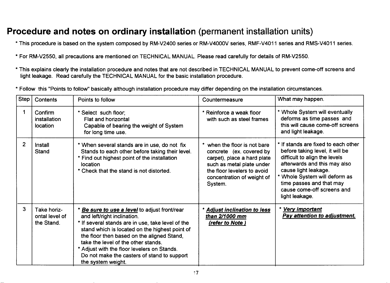
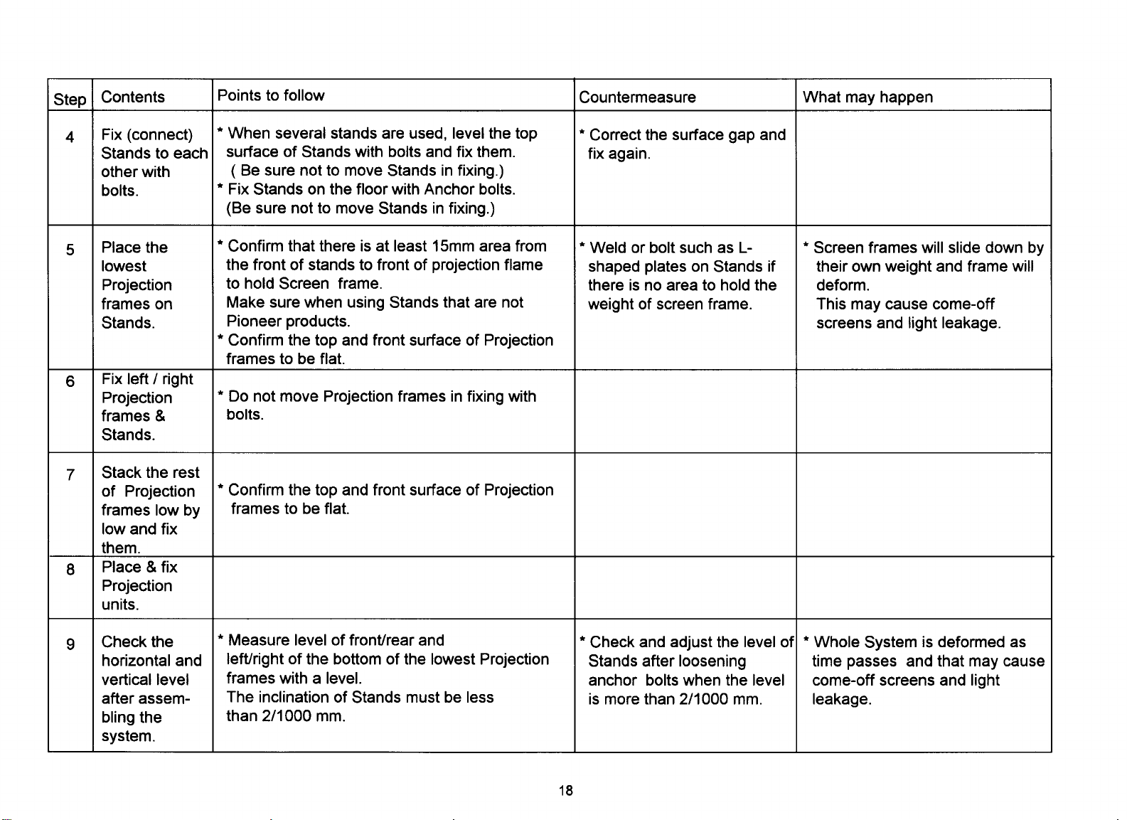
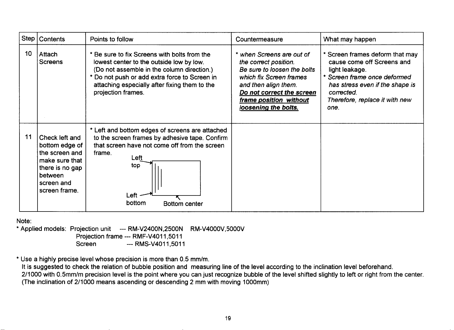
Page 1
TECHNICAL MANUAL (Ver.2.0)
MULTI PROJECTION UNIT
RM-V2550BU
RM-V2550E
PROJECTION SCREEN KIT
RM-V2550S
RM-V2550S2
MULTI VIDEO PROCESSOR
RMD-V3104U
RMD-V3104A
PROJECTION STAND
RMA-V5020
Caution
This symbol refers to a hazard or unsafe
practice which can result in personal in-
jury or property damage.
Notes:
Pioneer will accept no responsibilities for damages re-
•
sulting from problems with parts other than those supplied by Pioneer.
•
Performance shall be guaranteed solely when assembly
and adjustment is performed as prescribed in this technical manual.
•
For improvement purposes, the specifications and de-
sign described in this technical manual are subject to
change without notice.
1
Page 2

PIONEER RM-V2550
MANUAL.
This Acrobat (IE: a PDF file) version of the Pioneer manual was made from
the original digital document and has had some updated pages added into it. Because of this
some of the page numbers may be out of order.
As Pioneer is constantly working towards providing the best possible documentation for our
products, there may be an improved version of this document available. Please contact your
Pioneer representative for additional information.
Josh Kairoff
Pioneer New Media Technology.
Augest 7, 2000
Page 3

CONTENTS
CHAPTER 1 FEATURES .......................................................................................................... 5
1. FEATURES OF THE MULTI PROJECTION UNIT (hereinafter referred to as the “MPJ”) ............. 5
2. FEATURES OF THE MULTI VIDEO PROCESSOR (hereinafter referred to as the “MVP”)............ 6
3. FEATURES OF THE PROJECTION STAND (hereinafter referred to as the “Stand”).................... 6
CHAPTER 2 GENERAL SPECIFICATIONS .............................................................................7
1. SPECIFICATIONS OF THE DIFFERENT UNITS ................................................................................. 7
(1) Multi Projection Unit (RM-V2550BU, RM-V2550E) ................................................................... 7
(2) Projection Screen Kits ................................................................................................................. 8
(3) Multi Video Processor (RMD-V3104U, RMD-V3104A) ............................................................ 14
(4) Multi Video Processor (RMD-V3216/V3109/3000X) ................................................................ 19
(5) Projection Stand (RMA-V5020) ................................................................................................ 20
(6) Adjustment Control Unit (RU-V107) Option ............................................................................ 21
2. Diagram of system dimensions ....................................................................................................... 22
(1) Single panel ................................................................................................................................ 22
(2) 2 x 2 (100 inch) ............................................................................................................................ 23
(3) 3 x 3 (150 inch) ............................................................................................................................ 23
CHAPTER 3 INSTALLATION AND ASSEMBLY .................................................................. 24
1. INSTALLATION CONDITIONS......................................................................................................... 24
(1) Weight-tolerant ......................................................................................................................... 24
(2) Ceiling height ............................................................................................................................ 24
(3) Front space ................................................................................................................................ 24
(4) Rear space ................................................................................................................................. 24
(5) Stacking stages ......................................................................................................................... 24
(6) Installation work to prevent toppling ...................................................................................... 25
(7) Heat value calculation ............................................................................................................... 26
(8) Temperature and humidity conditions .................................................................................... 26
(9) Condensation ............................................................................................................................ 26
(10)Visual field angles, visible range ............................................................................................. 27
(11)Lighting ...................................................................................................................................... 30
(12)Effects of earth magnetism ...................................................................................................... 30
(13)Backyard ventilation .................................................................................................................. 30
(14)Power supply ............................................................................................................................. 31
(15)Cables used ............................................................................................................................... 32
(16)Semi-outdoor installation ......................................................................................................... 32
(17)Caution for use of user-prepared parts ................................................................................... 32
(18)Ventilation .................................................................................................................................. 33
2. INSTALLATION AND ASSEMBLY................................................................................................... 34
(1) Confirmation .............................................................................................................................. 34
(2) Unpacking .................................................................................................................................. 34
(3) Carrying the units after opening packaging ........................................................................... 37
3. PRECAUTIONS FOR TRANSPORTATION ...................................................................................... 39
4. ASSEMBLING THE SYSTEM ........................................................................................................... 40
(1) System assembly flowchart ..................................................................................................... 40
(2) Assembling the system ............................................................................................................ 41
(3) Installation without using stands (Direct floor installation) .................................................. 72
(4) Fixation using anchors ............................................................................................................. 73
(5) Connections (for 4 screen system) .......................................................................................... 75
5. SPECIAL INSTALLATION................................................................................................................. 76
(1) Wall inset ................................................................................................................................... 76
(2) Diagonal installation ................................................................................................................. 76
(3) Architrave processing ............................................................................................................... 76
(4) Upside down installation .......................................................................................................... 76
(5) Hanging from ceiling ................................................................................................................ 76
CHAPTER 4 ADJUSTMENTS ............................................................................................... 77
1. ADJUSTMENT PREPARATIONS ..................................................................................................... 77
(1) Wiring ......................................................................................................................................... 77
(2) Processing of wires ................................................................................................................... 78
(3) Aging .......................................................................................................................................... 78
(4) Adjustment signals ................................................................................................................... 78
(5) Equipment required for adjustments ...................................................................................... 79
2
Page 4

CONTENTS
2. BEFORE ADJUSTMENTS ................................................................................................................ 80
(1) Convergence adjustment memory .......................................................................................... 80
(2) TV system .................................................................................................................................. 81
(3) White balance adjustment memory ........................................................................................ 82
(4) Combined use of remote control and personal computer .................................................... 82
(5) Memory of adjustment data and settings ............................................................................... 82
(6) Assigning ID numbers .............................................................................................................. 83
(7) Focus adjustment ...................................................................................................................... 88
3. GENERAL EXAMPLES OF MULTI PROJECTION PRESENTATIONS ............................................ 89
(1) Switching between enlarged/individual display on the multi video processor ................... 89
(2) Switching the sources input to the multi video processor .................................................... 89
4. SCREEN ADJUSTMENTS ................................................................................................................ 90
(1) Adjustment flowchart ............................................................................................................... 90
(2) Convergence adjustment flowchart ........................................................................................ 91
(3) Convergence adjustment contents .......................................................................................... 92
(4) White balance adjustment flowchart ..................................................................................... 110
(5) White balance adjustment ...................................................................................................... 111
(6) External control by MPJ RS-232C .......................................................................................... 117
(7) Adjustments by remote control ............................................................................................. 129
CHAPTER 5 OPERATION AND MAINTENANCE ...............................................................144
1. MAINTENANCE .............................................................................................................................. 144
(1) Re-adjustments after 3 months .............................................................................................. 144
(2) Periodic maintenance ............................................................................................................. 144
(3) Replacement of parts .............................................................................................................. 144
2. CAUTIONS DURING PRESENTATIONS ....................................................................................... 145
3. SERVICING SYSTEM ..................................................................................................................... 146
4. CAUTIONS ON ASSEMBLY AND MAINTENANCE ..................................................................... 146
CHAPTER 6 PRECAUTIONS ...............................................................................................147
1. PRECAUTIONS ON FUNCTION AND PERFORMANCE OF SYSTEM ......................................... 147
2. NOT MALFUNCTION ..................................................................................................................... 148
3. CHECKING THE ADJUSTMENTS.................................................................................................. 149
4. CAUTION AND NOTES ON THE MPF INSTALLATION ............................................................... 150
5. NOTE IN USE OF THE OPTIONAL JOINT-LESS SCREENS......................................................... 150
6. TROUBLESHOOTING..................................................................................................................... 151
CHAPTER 7 MVP MANUAL ...............................................................................................152
1. INTRODUCTION ............................................................................................................................. 152
2. CONNECTION WITH MVP EXTERNAL COMPUTER .................................................................... 153
3. INSTRUCTIONS FOR USING A COMPUTER AS A TERMINAL .................................................. 154
4. OPERATING MODES ..................................................................................................................... 155
5. MVP VIDEO OUTPUT MODES ...................................................................................................... 157
6. ADJUSTMENT FUNCTIONS ......................................................................................................... 158
7. PICTURE FRAME ADJUSTMENT PROCEDURES ........................................................................ 159
1. Command reference ............................................................................................................... 159
(1) To shift to the operation mode [! command] ................................................................... 159
(2) To set different screens for adjusting convergence [DFFC command] .......................... 159
(3) To set the system back to 4-screen magnification [@ command] ................................. 160
2. Adjusting the picture frame ................................................................................................... 160
(1) To perform fine adjustment of the picture frame [&G command] ................................. 160
(2) To perform coarse adjustments of the picture frame [&P2, &Q2 commands] ............. 161
(3) To store the picture frame data [&W command] ............................................................. 162
(4) To load the picture frame data [&L command] ................................................................ 162
3. To switch the image input [IFF command] ........................................................................... 163
4. To indicate the current MVP state [SYS command] ............................................................. 164
5. To perform NTSC input board picture quality adjustment .................................................. 165
(1) To set the adjustment mode [AJYC command] ............................................................... 165
(2) To exit the adjustment mode [AJN command] ............................................................... 165
(3) Bright compensation [BRT command] ............................................................................. 166
(4) Color compensation [COL command] .............................................................................. 166
(5) Tint adjustment [TNT command] ...................................................................................... 167
3
Page 5
CONTENTS
6. Controls the panel switch function ........................................................................................ 167
(1) To set the manual mode [MNL command] ...................................................................... 167
(2) To set the remote mode [RMT command] ....................................................................... 167
(3) To select composite video input [CIC command] ............................................................ 167
(4) To select YC separation input [YIC command] ................................................................ 167
(5) To set the output to the NTSC mode [NT command] ..................................................... 168
(6) To set the output to standard RGB mode [NTR command] ............................................ 168
(7) To set the output to the double-speed RGB mode [NTD command] ............................. 168
(8) Optional variable scan board adjustment mode settings [:A command] ...................... 168
8. DEMO PATTERN SETTINGS AND CAUTIONS ............................................................................ 169
9. INSTALLING AND REMOVING BOARDS ..................................................................................... 170
10. RMD-V3020 COMMAND REFERENCE .......................................................................................... 172
(1) Outline of the RMD-V3020 ...................................................................................................... 172
(2) VS board command rules ....................................................................................................... 173
(3) Tracking adjustment [TRK command] ................................................................................... 175
(4) Contrast adjustment [CNT command] .................................................................................. 175
(5) R, G, B gain adjustment [RGN, GGN, BGN commands] ...................................................... 175
(6) Brightness adjustment [BRT command] ............................................................................... 175
(7) B, R clamp adjustment [BLV, RLV commands] ..................................................................... 176
(8) Blanking window level adjustment [BKL command] ........................................................... 176
(9) Horizontal, vertical direction screen display position adjustment [HPS, VPS commands] .. 176
(10)Horizontal, vertical blanking window position adjustment [HWN, VWN commands] ...... 177
(11)Horizontal, vertical blanking window width adjustment [HWD, VWD commands] .......... 177
(12)Full dot number compensation [HFD command] ................................................................. 178
(13)Freeze frame Y:ON N:OFF [FZY, FZN commands] ............................................................... 178
(14)Vertical filter ON/OFF [DSY, DSN, DSX commands] ............................................................ 178
(15)Vertical compression filter conversion rate input [LCV command] .................................... 179
(16)Program ROM version display [VER command] .................................................................. 179
(17)To indicate the current function setting [STS command] ................................................... 179
(18)To select preset model [M command] .................................................................................. 180
(19)Model fresh [F command] ...................................................................................................... 181
(20)Measurement data display [FRQ command] ........................................................................ 181
(21)Model table reference [TBL command] ................................................................................. 182
(22)Horizontal frequency input [HFQ command] ........................................................................ 183
(23)Vertical frequency input [VFQ command] ............................................................................. 184
(24)Vertical full-line input [VLN command] ................................................................................. 184
(25)All reset [ARS command] ....................................................................................................... 184
11. MODE 99 ......................................................................................................................................... 185
12. VS BOARD MODEL SELECTION ................................................................................................... 186
13. USING METHODS OF HFQ, VFQ, VLN ......................................................................................... 186
14. SELECTING THE SYNC SIGNAL ................................................................................................... 187
15. RMD-V3104J additional commands ............................................................................................. 188
WARNING
• prevent injuries and physical damages, always read and observe this manual and all labels on the system before
assembly, construction, and adjustments.
• Do not use the system outdoors to prevent fire hazards and electric shocks caused by water entering the system.
• To prevent injuries, take note of the sharp edges of this system.
• When performing setup work at high places, to prevent the falling down of the system and damages caused by
falling objects, set the Keep Out area.
• To prevent fire hazards and electric shocks, do not place foreign objects in the system nor remodel it.
• To prevent fire hazards, observe the following using environment.
Temperature : 5 to 35 °C
Humidity : 20 to 80%
• Perform ventilation with the fan etc. and observe the operating environment conditions even after completing assembly.
• Never install the system tilted.
4
Page 6
Page 7
Page 8
Page 9
Page 10
Page 11
Page 12
Page 13
Page 14
Page 15

CHAPTER 1. FEATURES
FEATURES
1. FEATURES OF THE MULTI PROJECTION UNIT
(hereinafter referred to as the “MPJ”)
¶ Thin, space-saving design (75 cm deep), and installable flush against the wall (when stacked in two levels in
a 4-screen configuration, etc.)
¶ Split structure for easy carrying and assembly
The structure is split by screen, making it easy to carry and assemble the system.
¶ Excellent features with a reasonable price
¶ Can be stacked in up to three levels
¶ Under 2 meters high when stacked in two levels, allowing installation in stores with low ceilings
¶ Improved adjustment procedures
• Uniform, simplified ABL level adjustment using ABL control voltage indication.
• Lists of main deviation and white balance adjustment values can be displayed when performing adjustments
with the remote control unit, making it simple to check adjustment values and compare with other screens.
¶ Variety of screens available
1. Screw width approx. 4mm (RM-V2550S)
2. Screw width 1mm (RM-V2550S2)
¶ Usable in bright places
High screen brightness (420 ft-L), allowing use in lobbies exposed to external light and bright offices.
¶ Full of functions for providing high picture quality with enlarged images and a strong sense of picture unifor-
mity
• Though the peripheral brightness is sufficient for multi-screen images, a “multi” function is also included for
activating a peripheral light compensation circuit and achieving enlarged pictures with even more uniform
brightness. There is also a function for achieving the optimum contour compensation level with enlarged
images, thereby providing natural, high quality enlarged pictures.
• An auto white balance function and ABL (Auto Brightness Limiter) linking function suppress differences in
colors and brightness on the different screens.
¶ Convergence memory function
Up to three sets of adjustment data in addition to the standard factory default settings can be stored in the
memory.
5
Page 16

FEATURES
¶ “Color mode selection function” for convenient camera reshooting
The MPJ is equipped with a “color mode selection function” allowing the selection of two white balance data
settings. When used for example in a broadcast station’s studio for reshooting, the colors will be unnatural if
a camera suited to the brightness in the studio is used, but if one color temperature is set to 4500°K, natural
colors can be reproduced at the touch of a button.
¶ On-screen display function
Adjustment values and various settings can be displayed on the screen.
¶ External control function
The MPJ is equipped with an RS-232C external control terminal. This makes it possible to use a computer to
perform the various adjustments, and provides possibilities for various types of visual presentations. Transfer of control signals to the individual multi projection units is possible in daisy chain format by connecting
the combination terminals using interconnection control cables (DIN 6-pin connectors, included). No complicated connections are necessary. The multi projection units can be assigned ID numbers and still be adjusted
individually after the system is expanded.
¶ Dual NTSC/PAL compatibility
The individual multi projection units display high quality pictures with either NTSC or PAL inputs.
¶ Wired remote control unit (RU-V107, sold separately) available for adjustments
The wired remote control unit can be used for adjusting the convergence, white balance and other settings
while watching the picture from the front when setting up the multi picture system.
2. FEATURES OF THE MULTI VIDEO PROCESSOR
(hereinafter referred to as the “MVP”)
¶ Multi video processor for 4-screen enlarged images
¶ Compact, space-saving design
¶ Adjustment remote control unit/computer relay function considering system installation
¶ Expandable through the addition of an option board (one)
3. FEATURES OF THE PROJECTION STAND
(hereinafter referred to as the “Stand”)
¶ EIAJ rack mount function
¶ Casters for easy moving
¶ Built-in adjuster for level adjustment
6
Page 17

CHAPTER 2. GENERAL SPECIFICATIONS
GENERAL SPECIFICATIONS
1. SPECIFICATIONS OF THE DIFFERENT UNITS
(1) Multi Projection Unit (RM-V2550BU, RM-V2550E)
TV format ............... NTSC/PAL, automatic switching
(fixed mode available)
Projection tubes..........................................7" CRT x 3
Horizontal resolution ..... 800 TV lines (with video input)
Brightness (at white peak) .....................420 ft-L (50")
Practical angle of vision 150° horizontal, 60° vertical
Input signal:
Video input
...... Standard input level (75-ohm load) 1 Vp-p
Input terminal: BNC connector x 1
Y/C isolated inputs
.................. Standard input level (75-ohm load)
Brightness (Y) signal 1 Vp-p
Color (C) signal ... 286 mVp-p (burst signal, NTSC)
300 mVp-p (burst signal, PAL)
Input terminals: BNC connectors
(one each for Y and C)
RGB input ............................ Analog R.G.B signals
(NTSC/PAL R.G.B)
RGB-1: D-Sub 9-pin terminal x 1 *2
RGB-2: BNC connector x 5 *2
R: Red input, 0.7 Vp-p ±2 dB, 75-ohm terminal,
positive polarity
G/G on SYNC: Green input, 0.7 Vp-p ±2 dB,
75-ohm terminal, positive polarity
Green input with synchronization,
1.0 Vp-p±2 dB, 75-ohm terminal, positive polarity
B: Blue input, 0.7 Vp-p ±2 dB, 75-ohm terminal,
positive polarity
HD/SYNC: Horizontal synchronization input,
0.3 to 4 Vp-p, 75-ohm terminal,
negative polarity
Composite synchronization input,
0.3 to 4 Vp-p, 75-ohm terminal,
negative polarity
VD: Vertical synchronization input, 0.3 to 4 Vp-p,
75-ohm terminal, negative polarity
Synchronizing signal frequency: Standard NTSC
or PAL frequency
EXT control: BNC connector
Remote input: Mini-jack
Auto input: 6-pin DIN connector
Output signal:
Video output .... Standard level (75-ohm load) 1 Vp-p
Outputs input signals from input terminals
Remote output ...................... 6-pin DIN connector
Computer control:
Method ........................... RS-232C (D-SUB 25-pin)
Speed .........1200, 2400, 4800, 9600, 19200 bps *1
Power supply voltage
for RM-V2550BU ......... AC 100V to 120V, 50/60 Hz
for RM-V2550E ............ AC 220V to 240V, 50/60 Hz
Normal power consumption
for RM-V2550BU ........................ approx. 300W *3
for RM-V2550E ........................... approx. 300W *3
Maximum power consumption
for RM-V2550BU .......................................... 400VA
for RM-V2550E ............................................. 400VA
AC outlet (Max. 8A, AC 100V to 120V)
for RM-V2550BU ................................................... 1
AC outlet (Max. 550W/A, AC 220V to 240V)
for RM-V2550E ...................................................... 1
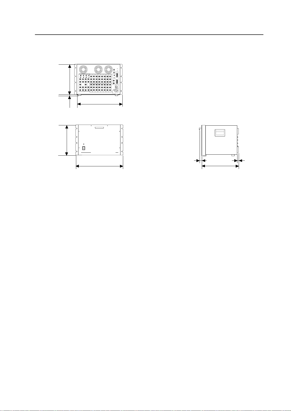
External dimensions
.............. 1030.8 (W) x 1115 (H) x 665.2 (D) mm
(when RM-V2550S or RM-V2550 S2 fitted:)
1030.8 (W) x 1115.5 (H) x 750 (D) mm
Weight ................................................................. 74 kg
(87kg when RM-V2550S fitted)
(82kg when RM-V2550S2 fitted)
Accessories
(RM-V2550BU, RM-V2550E)
Power cord ................................................... 1 *4
Control cable..................................................... 1
Used to control multiple multi projection units.
Hexagonal bolt w/ washer (M8x65) ................ 2
Hexagonal bolt w/ washer (M8x45) ................ 3
Hexagonal nut (M8).......................................... 5
Light shield (black) ........................................... 4
*1 The RS-232C baud rate is set at 4800 bps upon
shipment from the factory. The setting can be
changed by remote control or from a computer.
*2 Only RGB-1 or RBG-2 can be used (selected by
switch).
*3 NTSC color bar signal input and other adjustment
data as set upon shipment from the factory.
*4 Bolts for connecting the MPJ to a stand are not
included with the MPJ (they are included with the
standard stand)
7
Page 18

GENERAL SPECIFICATIONS
(2) Projection Screen Kits
1 4mm-screw screen (RM-V2550S)
External dimensions ....... 1030.8 x 768.5 x 84.8mm
Weight ................................................................ 13kg
Accessories
Hook fitting (left) ................................................. 1
Hook fitting (right) .............................................. 1
Screen frame fastener ........................................ 1
Cross-recessed tap tight screws
(wood screws, nominal diameter 4, length 18) .. 2
(nominal diameter 4, length 8) ........................ 18
Cross-recessed small screw (M6x10) ................ 1
Cross-recessed tap tight screw with metal washer
(nominal diameter 4, length 12) ........................ 1
2 1mm-screw screen (RM-V2550S2)
External dimensions ....... 1030.8 x 768.5 x 84.8mm
Weight .................................................................. 8kg
Accessories
Hook fitting (left) ................................................. 1
Hook fitting (right) .............................................. 1
Screen frame fastener ........................................ 1
Connector ............................................................ 1
Cross-recessed tap tight screws
(nominal diameter 4, length 10) ...................... 10
(nominal diameter 4, length 12) ........................ 1
(nominal diameter 4, length 18) ........................ 2
Cross-recessed tap tight screws
(M4, length 25) .................................................... 3
(M6, length 10) .................................................... 1
Pin ........................................................................ 1
*1 When either above-mentioned 1 or 2 is used as
a single-panel screen, you will need one more set
consisting of a screen frame fastener etc., and so
you should obtain the following service parts set:
AAX1056
8
Page 19
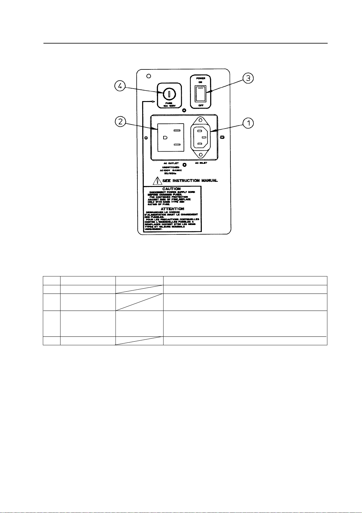
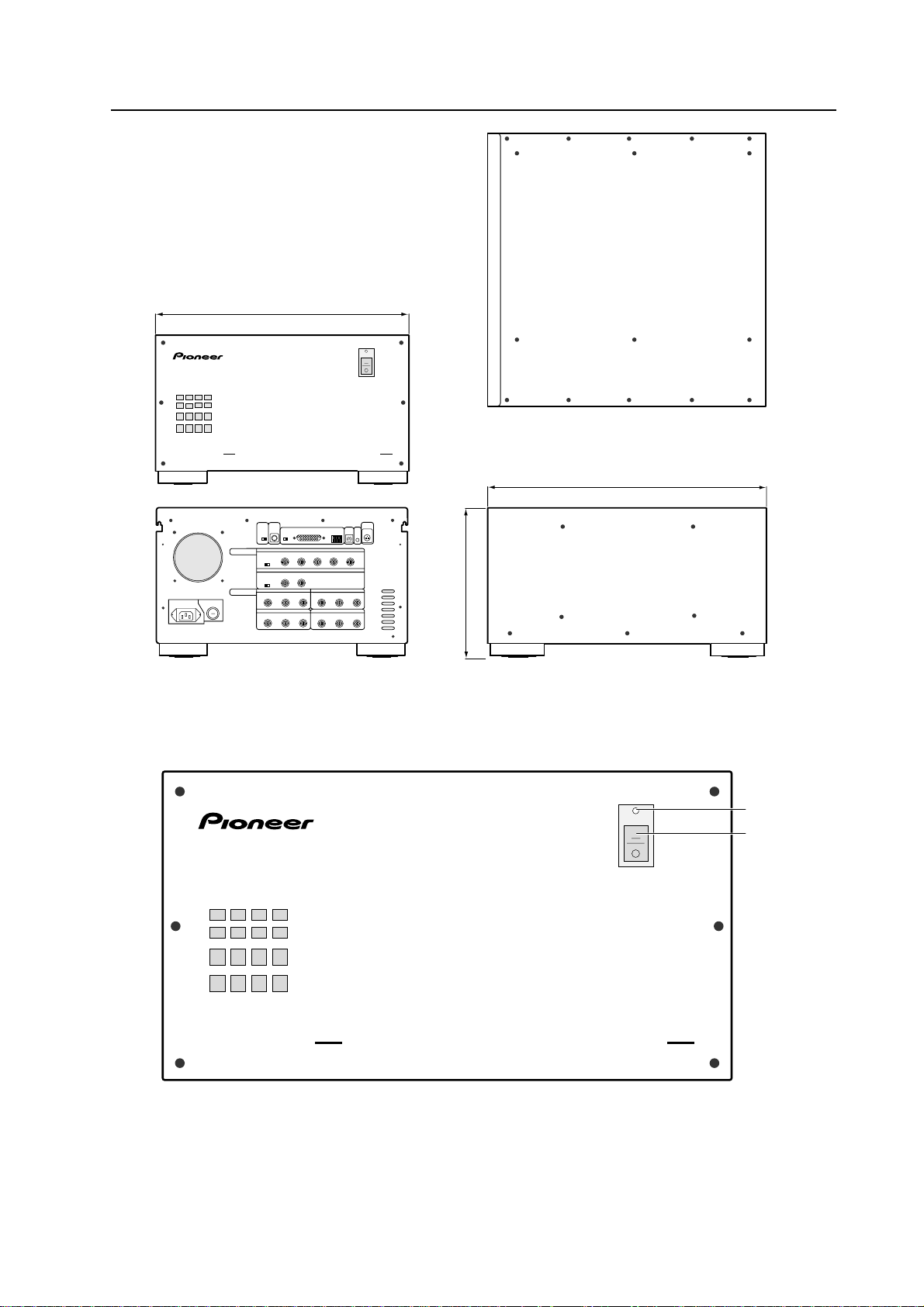
Power Supply Panel
GENERAL SPECIFICATIONS
[Fig. 2-1-1]
No. Name Type Function
1 AC inlet Connect the power cord here.
2 AC outlet Connect other multi projection units here. Not linked to main
power switch. (*1)
3 Main power switch Seesaw switch Turns the power supply to the set on and off. When on, the set
is set to the mode stored in the last memory (standby or
power on).
4 Fuse holder The fuse is in here. Only service personnel should touch this.
NOTE) 1. Refer to “(13) Power supply 3 connection”.
9
Page 20
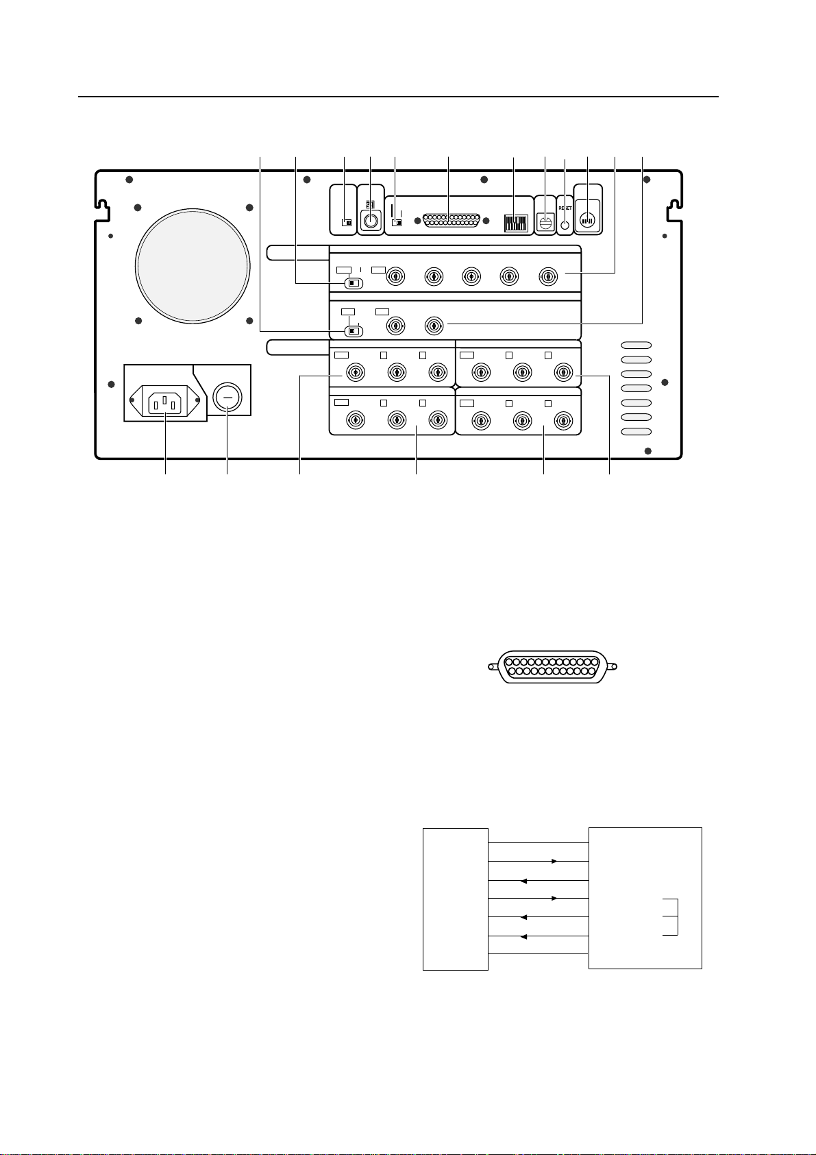
GENERAL SPECIFICATIONS
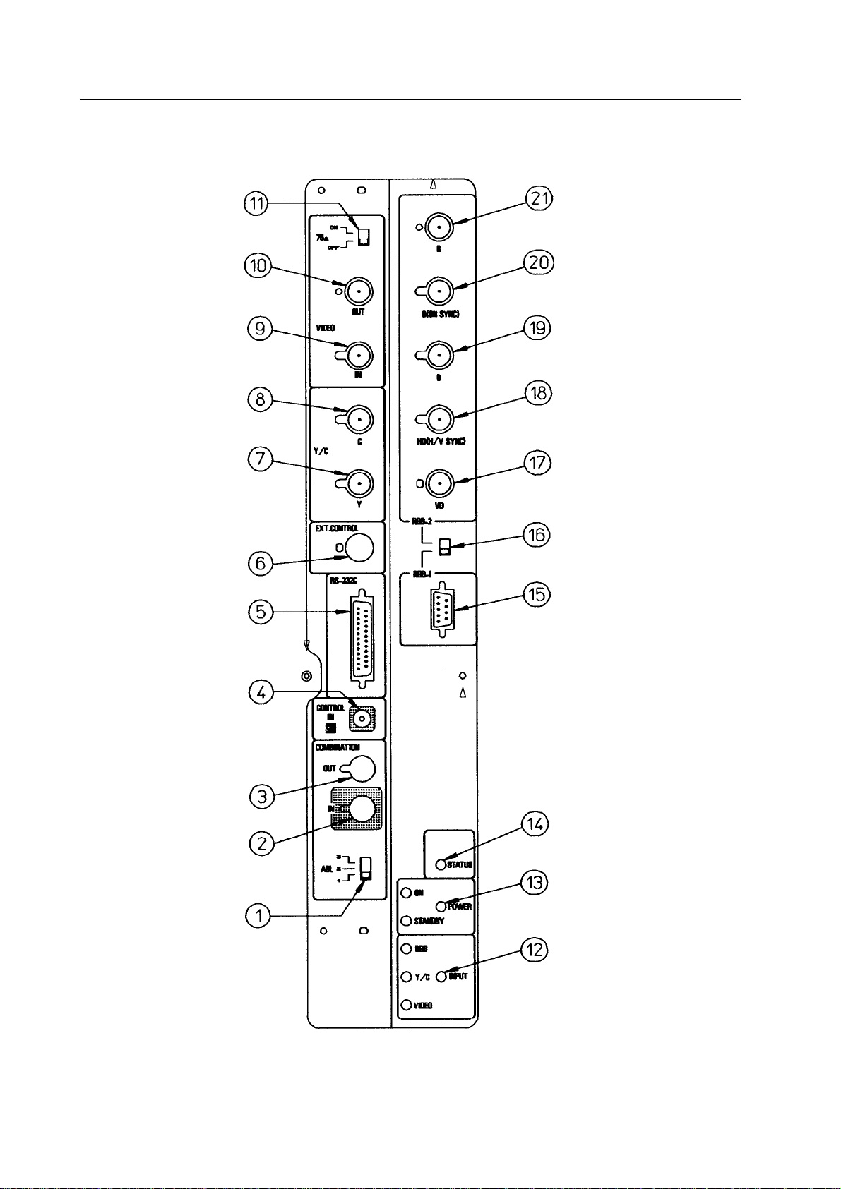
Control Panel
10
[Fig. 2-1-2]
Page 21
GENERAL SPECIFICATIONS
No. Name Type Function
1 ABL linking switch Slide switch When ABL linking is on, the ABL linking control
voltage’s control quantity can be switched
2 Linked input terminal DIN 6-pin ABL, remote control signal and RS-232C signal input
terminal
3 Linked output terminal DIN 6-pin ABL, remote control signal and RS-232C signal output
terminal
4 Remote control connector Mini jack Jack for connecting adjustment remote control unit
(sold separately)
5 RS-232C port D-sub 25-pin RS-232C communications connector
(female)
6 Control input terminal BNC connector Video input and Y/C input external switching control
signal input terminal
7 Y (brightness) BNC connector Brightness signal input terminal
input terminal
8 C (color) input terminal BNC connector Color signal input terminal
9 Video input terminal BNC connector Video signal input terminal
0 Video output terminal BNC connector Video input terminal 9 through out terminal
- Terminating switch Slide switch Turn on to terminate video input terminal 9 at 75 ohm
= Input selector switch Tact switch Video input, Y/C input, RGB input selector switch.
At the VIDEO position, switching between the video
input and Y/C input is possible with the external control
signal 6.
~ POWER switch Tact switch When power off: STANDBY (red LED) lights
When power on: ON (green LED) lights
! STATUS indicator switch Tact switch Switch for displaying the total power on time (*), switch
settings, etc., on the screen
@ RGB input terminal D-sub 9-pin (male) RGB signal input terminal
# RBG input selector switch Slide switch Switch for selecting the RGB signal input terminal
format
$ RGB input terminal BNC connector RGB signal vertical synchronization input terminal
(vertical synchronization)
% RGB input terminal BNC connector RGB signal horizontal synchronization and composite
(horizontal synchronization synchronization (for only input signal H/V synchronization)
/composite synchronization) input terminal
^ RGB input terminal (B) BNC connector RGB signal B input terminal
& RBG input terminal BNC connector RGB signal G or G on Sync input terminal
(G/G on Sync)
* RBG input terminal (R) BNC connector RGB signal R input terminal
¶ Turn the power off with the POWER switch ~ on the set, through RS-232C control or with the wired remote
control unit (sold separately). (If the power supply is interrupted with the main power switch or if the power
cable is disconnected from the outlet, the switch settings in ! above, the TV system and the convergence
memory settings will not be stored in the last memory.)
Thus, for permanent installations, to start up and stop the entire system by turning the AC power on and off,
the power must first be turned off as described above in order to store the settings in the last memory.
(Refer to “Chapter 4, 2 (5) Last memory of adjustment data and settings “.)
* Total power on time
Only counted when power is set to ON.
11
Page 22
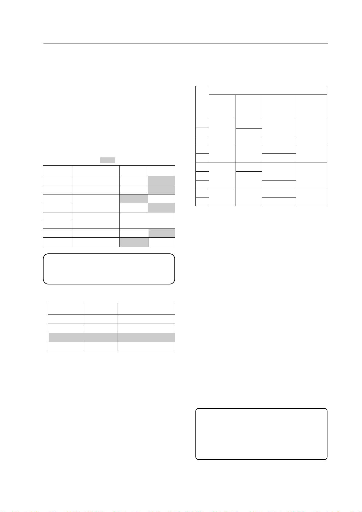
GENERAL SPECIFICATIONS
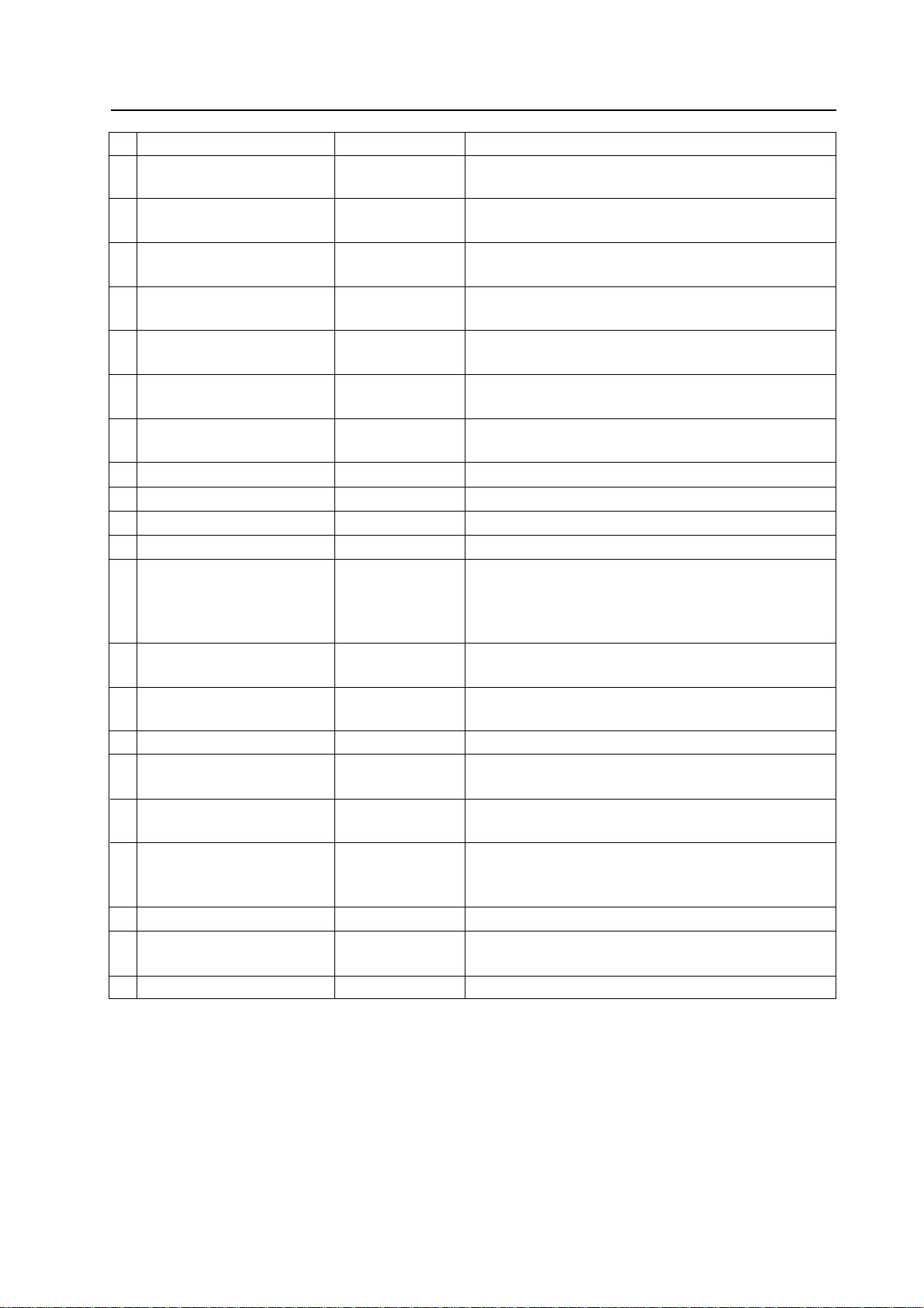
Control Panel Mode Switches
¶ INPUT SELECT switch
Position Function
VIDEO Selects the VIDEO input terminal. When selected, the VIDEO LED
¶ The input switches each
time the switch is pressed.
Y/C The Y/C input terminal is selected.
RGB The RGB input terminal is selected.
lights. This position is also used for switching the input between
VIDEO and Y/C by inputting a control signal to the EXT. CONTROL terminal.
< EXT. CONTROL >
The input switches between VIDEO and Y/C when a control signal is input to the EXT. CONTROL terminal (BNC).
In this case, the VIDEO LED remains lit, regardless of which input
is selected.
Control signal Open : VIDEO
Low : Y/C
When the control input terminal is open (normal mode), the
open mode is set and the VIDEO input signal is selected.
When selected, the Y/C LED lights.
When selected, the RGB LED lights.
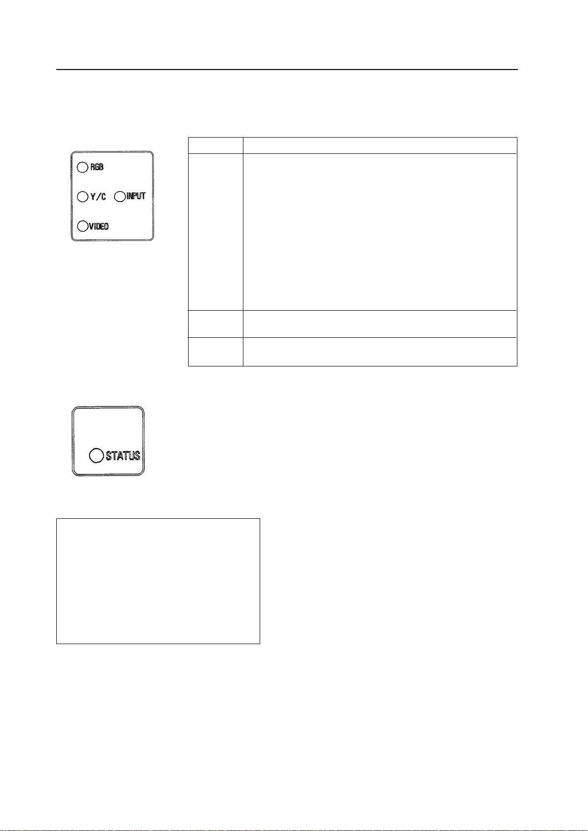
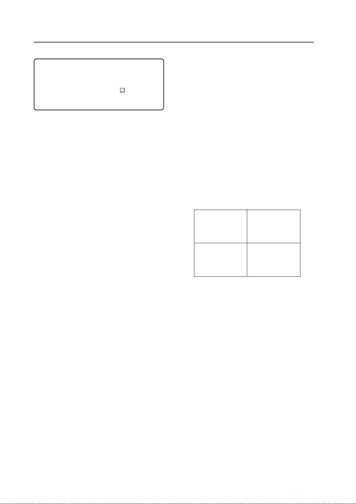
¶ STATUS indicator switch
Display example)
1.HOUR
2.INPUT
3.MULTI
4.COLOR MODE
5.COMBI.
6.VIDEO MODE
7.BAUD RATE
8.TV SYSTEM
9.CONV. DATA
1000 H
VIDEO
ON
1
ON
ON
4800BPS
AUTO/NTS
MEMO-1
¶ The display of the various settings turns on and off when the
switch is pressed.
1: Indicates the total power on time. (Only counted
when power is set to ON.)
2: Indicates the selected input.
3: Indicates the MULTI ON/OFF mode.
4: Indicates the COLOR MODE 1/2 mode.
5: Indicates the COMBINATION ON/OFF mode.
6: Indicates the picture muting on/off mode when
the input function is switched.
7: Indicates the transfer speed for computer con-
trol.
8: Indicates the TV system mode.
9: Indicates the memory area status for the selected
convergence data.
12
Page 23
GENERAL SPECIFICATIONS
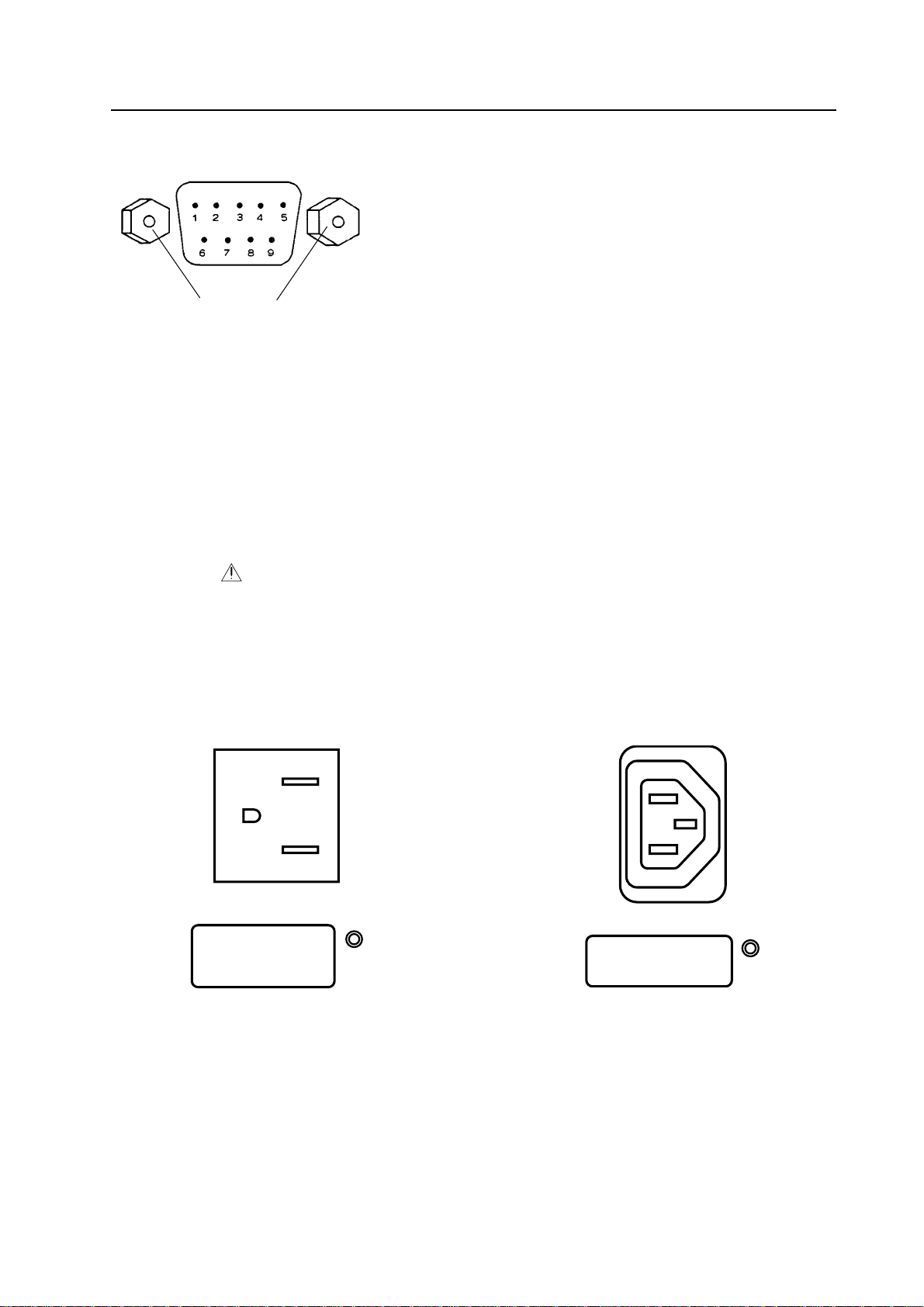
AC OUTLET
»
UNSWITCHED
AC220-240V~ 550W
[RGB-1 terminal]
Analog RGB : 0.7 Vp-p (75 ohm)
Synchronizing signal : 0.3 Vp-p to 4 Vp-p (75 ohm)
Connection terminal : 9-pin D SUB (male)
Pin layout 1 : R 6 : GND
2 : G/G on Sync 7 : VD
3 : B 8 : NC
M2.6 inner thread screw
4 : Signal GND 9 : NC
5 : HD/Sync
[VIDEO input]
The video output terminal outputs the signal input to the input terminal (through out). When connecting other
devices, terminate the other device at 75 ohm and set the unit’s 75-ohm terminating switch to “OFF “ (open).
When not connecting other devices, always set the terminating switch to “ON”.
Power outlet
¶ Power outlet (unswitched)
RM-V2550BU ...... MAX. 8A/AC 100V to 120V
RM-V2550E ......... MAX. 550W/AC 220V to 240V
This outlet is for adding multi projection units. Do not use it for other purposes.
¶ Power outlet power consumption
Up to two other multi projection units can be connected after one multi projection unit.
AC OUTLET
UNSWITCHED
AC100-120V 8AMAX
50/60Hz
»
RM-V2550BU
RM-V2550E
13
Page 24

GENERAL SPECIFICATIONS
(3) Multi Video Processor (RMD-V3104U, RMD-V3104A)
Input signal
Input video signal
1 set ............................................... BNC connector
for RMD-V3104U .................................... NTSC
for RMD-V3104A .............................. NTSC/PAL
(One set of RGB inputs can be added by adding an
optional variable scan board.)
1 Composite video signal....................... 1.0 V (p-p)
(75-ohm terminated)
2 Isolated Y/C signal
Y (with synchronization) ..... 1.0 V (p-p) (75 ohm)
C ...................................... 0.286 V (p-p) (75 ohm)
* Signal format 1 or 2 selectable
3 Optional RGB input signal
RGB signal ............................0.7 V (p-p) (75 ohm)
H.V ........................................................... TTL level
C SYNC ................ 0.3 to 4 V (p-p), negative logic
Green (G on Sync) ............... 1.0 V (p-p) (75 ohm)
SYNC section ....................................... 0.3 V (p-p)
SYNC order of priority
H.V > C SYNC > Green (G on Sync)
RS-232C control input 25-pin D-sub
Output signal
Output video signal
4 sets ...............................................................BNC
1 Composite video signal...... 1.0 V (p-p) (75-ohm)
2 Isolated Y/C signal
Y (with synchronization) ..... 1.0 V (p-p) (75 ohm)
C ......................................0.286 V (p-p) (75 ohm)
* Simultaneous output of 1 and 2
3 RGB signal
Green (Sync on Green) ........................ 1.0 V (p-p)
SYNC section ....................................... 0.3 V (p-p)
Blue ....................................................... 0.7 V (p-p)
Red ........................................................ 0.7 V (p-p)
* PAL output is available for only signal 3.
Others
Power supply
for RMD-V3104U ................... AC 100V (50/60 Hz)
for RMD-V3104A ......... AC 220 – 240V (50/60 Hz)
Maximum Power consumption...................... 100 W
for RMD-V3104U ..............................100W/200VA
for RMD-V3104A .............................. 100W/200VA
Operating temperature/humidity range .......... 5 to 35°C
85% or less (without condensation)
External dimensions
.....................377 (W) x 382 (D) x 204 (H) (mm)
Weight .............................................................12.0 kg
14
Page 25
External Dimensions
377
MULTI VIDEO PROCESSOR RMD-V3104J
GENERAL SPECIFICATIONS
382
Front Panel
INPUT
OUTPUT
204
POWER
ON
OFF
Unit: mm
1
2
1 POWER indicator
Lights when the power is ON.
2 POWER switch
Press to switch the power ON/OFF.
MULTI VIDEO PROCESSOR RMD-V3104J
15
Page 26
GENERAL SPECIFICATIONS
Rear Panel
~
9
2134
INPUT
OPTION
V IN
INPUT
OUTPUT
FUSE 125V 3.15AAC INLET
!
@
ON OFF
( )
VBS
VBS VBS
VBS
GBR
VBS
GBR
5
CONTROL
IN
DISPLAY
MVP RATERS-232C MODE
V.FIL
G
( )
VBS
(Y)
(Y/C)
Y/C
YC
V OUT1 V OUT2
Y C
V OUT3 V OUT4
Y C
6
OPTION
B
(C)
V IN
#
R H/CS
VBS
GBR
VBS
GBR
8
7
V
Y C
Y C
0-
COMB
OUT
%$
=
1 VBS/ Y/C switch
Selects whether the VBS (video signal) or Y/C
signals are input to the V IN (Video) input.
The factory preset is VBS (video signal).
2 V.FIL (Vertical interpolation filter) ON/
OFF switch
When the optional variable scan board (RMDV3020) is installed, use this switch to switch the
vertical interpolation filter ON/OFF. Set this
switch to ON if the top and bottom of the computer screen image cannot be accommodated
entirely by the screen.
The factory preset is set to ON.
3 INPUT switch
Selects whether the V IN (Video) or OPTION input
is enlarged into 4 screens.
The factory preset is set to V IN.
* Always press the reset button after changing
the position of this switch.
4 Remote control input connector
Connects the display’s remote control unit.
(Adjustment or changes to the settings of the
unit cannot be accomplished with the remote
control unit.)
6 RS-232C connector
Connects RS-232C cable.
< RS-232C connector diagram >
RS-232C pin layout
13 1
25 14
< RS-232C connection diagram >
Use an RS-232C straight cable for connection.
<External computer> <MVP unit>
RS-232C RS-232C IN connector
FG 1 1 FG
TxD 2 2 RxD
RxD 3 3 TxD
RTS 4 4 RTSI
CTS 5 5 CTSI
DSR 6 6 DSRI
SG 7 7 SG
straight cable
* Pins 4, 5 and 6 are internally shorted.
5 RS-232C switch
When performing adjustments from a computer,
use this switch to switch between this unit (MVP)
and display (DISPLAY).
16
• Pins which are not shown in the diagram are not
used.
Page 27
GENERAL SPECIFICATIONS
Signal name
FG ............................. Frame Ground
TxD ...................... Transmitted Data
RxD ............................ Received Data
RTS ........................ Request to Send
CTS ............................. Cleat to Send
DSR .......................... Data Set Ready
SG ............................. Signal Ground
7 Baud rate switch
Selects the baud rate for the RS-232C.
Baud rate switch (8-bit DIP switch)
Functions of bits : Factory preset values
Switch No. Function ON OFF
1 Parity Yes No
2 Parity polarity Even Odd
3 Character bits 8 bits 7 bits
4 Stop bits 2 bits 1 bit
5
Baud rate setting See table below.
6
(Note)
7 Reserved
(Note)
8 Reserved
8 MODE switch
Selects the video output mode.
MODE switch details
SW
Frequency
No.
mode
NTSC
0
1
2
PAL
4
5
NTSC
8
9
A
PAL
C
D
• The factory preset is “8” for RMD-V3104U.
• Frequency mode
NTSC ........................ Vertical refresh rate 59.94Hz
PAL ........................... Vertical refresh rate 50.00Hz
Output Mode Details
Output
mode
VBS,Y/C
Standard/
Double scan
Standard
RGB
Double scan
RGB
Standard
Double scan
VBS,Y/C
Standard
RGB
Double scan
RGB
Standard
Double scan
Middle cut
recovery
mode
OFF
OFF
ON
ON
(Note)
SW7 should always be set to OFF.
SW8 should always be set to ON.
Baud rates available with SW 5 and 6
SW5 SW6 Baud rate (bps)
ON ON 19200
OFF ON 9600
ON OFF 4800
OFF OFF 2400
• Output mode
VBS (Video signal), Y/C or RGB is able to selected.
Yet, VBS, Y/C output are useful is only NTSC Standard
mode.
• Standard / Double scan
Standard (Interlace) ................................................
................. Horizontal frequency 15.625kHz(PAL),
.............. Horizontal frequency 15.734 kHz(NTSC)
Double scan (Non-interlace) ..................................
................ Horizontal frequency 31.250 kHz(PAL),
.............. Horizontal frequency 31.468 kHz(NTSC)
• Output mode
It is the function that mitigates the trunk piece
phenomenon by multiple visions unique scanning line
structure. There is a difference in an effect by the
magnification ratio and it is more effective as smaller of
the magnification ratio. Yet, it does not work in vertical
magnification ratio X 1.
CAUTION:
The Frequency mode for each input board is as follows.
Variable scan board ................................. NTSC, PAL
PAL / NTSC input board .............................................
.................. NTSC (NTSC source), PAL (PAL source)
In the case that a MODE NO other than the above is
set up, a proper picture is not output.
17
Page 28
GENERAL SPECIFICATIONS
CAUTION:
MVP has each separete position data in PAL and
NTSC. When a mode is changed between PAL and
NTSC, a video image position is initialized to data that
was preserved with each mode before. Do so that you
preserve adjustable data with &W1 without fail, in
the case that a mode is changed after video image
position adjustment. (Refer to &W command)
9 Reset button
Press this button to reset the system. After the
button is pressed, the system enters the manual
mode. In manual mode, this unit can be controlled
using the rear panel switches, without using a
computer.
When the reset button is pressed, this unit
functions in the modes selected by the rear panel
switches.
0 COMB cable connector
Connects the interlock cable (cord with 6P miniDIN plugs) provided with the display.
- OPTION video input connectors
These input connectors are used when an option
board is installed.
When the RMD-V3020 variable scan board is used,
their functions operate as shown below.
~ AC INLET
Connects the power cord to the unit.
! FUSE
Use only a fuse with the specified capacity.
Unplug the power cord before replacing the fuse.
@~% V OUT connectors 1 to 4
These video output connectors output enlarged
video image signals for the 4 screens.
VBS/G ...... Output terminal of the composite video
signal or the G signal of RGB separate
signals. (Also outputs the G On Sync
signal while it outputs the G signal.)
Y/B ........... Output terminal of the Y signal or the
B signal of RGB separate signals.
C/R ........... Output terminal of the C signal or the
R signal of RGB separate signals.
The correspondence between these outputs and
a 4 displays is shown below.
V OUT1
V OUT2
G .................... Input terminal for the G signal
of RGB separate signals.
B .................... Input terminal for the B signal
of RGB separate signals.
R .................... Input terminal for the R signal
of RGB separate signals.
H/CS .............. Input terminal for the H sync or
C SYNC signal.
V .................... V sync input terminal.
• As the NEC PC-9800
computers use H/V separate sync signals, their
sync signals should be connected to both the H/
CS and V connectors. H and CS use a common
connector.
• Macintosh
which should be connected to the H/CS
connector.
®
computers use the CS sync signal,
®
, IBM PC and DOS/V (VGA)
= V IN (video) input connectors
These connectors receive video data (V IN signal
images).
Apply V IN (Video) input signals to these
connectors.
VBS/Y ...... Input terminal for the composite video
signal or the Y signal of Y/C separate
signals.
C ............... Input terminal for the C signal of Y/C
separate signals.
V OUT3 V OUT4
4 displays (front view)
18
Page 29
(4) Multi Video Processor (RMD-V3216/V3109/V3000X)
Rear
0
0
299
15
GENERAL SPECIFICATIONS
430
unit: mm
SideFront
D
314
POWER
ON
OFF
MULTI VIDEO PROCESSOR RMD-V3216
16
482.6
420
[Fig. 2-1-3]
General Specifications of the Multi Video Processor (RMD-V3216/V3109/V3000X)
Input signal
Input video signal (up to 4 sets can be added)
2 sets (RMD-V3216) or 1 set (RMD-V3109) or
0 set (RMD-V3000) ............................ BNC connector
1 Composite video signal.......................... 1.0 Vp-p
(75-ohm terminated)
2 Isolated Y/C signal
Y (with synchronization) ............. 1.0 Vp-p (75 ohm)
C burst level ............................. 0.286 Vp-p (75 ohm)
* Signal format 1 or 2 selectable
* Input 1 only equipped with terminating
switch, through out
Input reference synchronizing signal ... BNC connector
1 Composite synchronizing signal
............................................... 0.286 to 4.0 Vp-p
2 Composite video signal
Image level............... 0 to 0.714 Vp-p (75 ohm)
Sync. Level ...................... 0.286 Vp-p (75 ohm)
* Equipped with terminating switch, through
out
RS-232C control input 25-pin D-sub
Output signal
Output video signal
16 sets (RMD-V3216) or 9 sets (RMD-V3109) or
0 set (RMD-V3000) ............................ BNC connector
1 Composite video signal ..... 1.0 Vp-p (75-ohm)
2 Isolated Y/C signal
Y (with synchronization) .... 1.0 Vp-p (75 ohm)
C (with burst) burst level.. 0.286 Vp-p (75 ohm)
* Simultaneous output of 1 and 2
3 RGB signal
Green (G on Sync) .............................. 1.0 Vp-p
SYNC section ...................................... 0.3 Vp-p
Blue ...................................................... 0.7 Vp-p
Input reference synchronizing signal BNC connector TTL level
(or input reference synchronizing signal through
out)
Others
Power supply .................AC 100 to 120 V (50/60 Hz)
Power consumption
...... (RMD-V3216, RMD-V3109, RMD-V3000X)
350 W, 700 VA
Operating temperature/humidity range ... 5 to 35°C
85% or less (without condensation)
External dimensions
(RMD-V3216, RMD-V3109, RMD-V3000X)
................. 482.6 (W) x 420 (D) x 314 (H) (mm)
(not including handle)
Weight
RMD-V3216 .................................................... 22.5 kg
RMD-V3109 .................................................... 22.0 kg
RMD-V3000X ................................................. 20.5 kg
Accessories
Rack mount screw M5 ............................................ 8
Rack mount washer ................................................ 8
* Up to 3 units of the RM-V2550BU can be stacked.
4x4 (16-screen) configurations are not possible.
19
19
Page 30
GENERAL SPECIFICATIONS
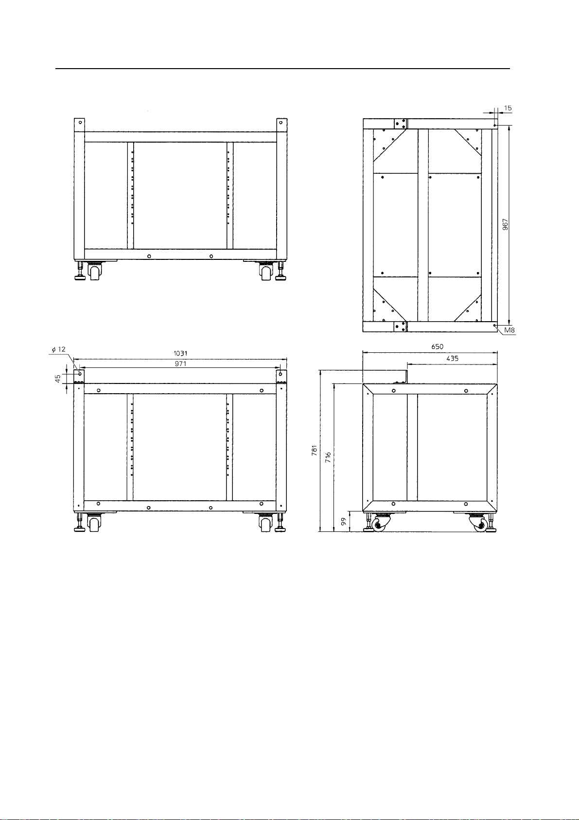
(5) Projection Stand (RMA-V5020)
Rear
Top
Front
[Fig. 2-1-4]
Specifications
External dimensions (max.) .......................... 1031 (W) x 781 (H) x 650 (D) mm
(For 100-inch 4-screen systems, system height is 2600 mm)
Weight ............................................................ 51.5 kg
Accessories
Main unit mount bolt M8x30 ........................ 2
Main unit mount bolt M8x60 ........................ 2
Side coupling bolt M10x120 ......................... 4
Side coupling washer (for M10 bolt) ............ 8
Side coupling nut (for M10 bolt) .................. 4
Package dimensions .......................................... 1165 (W) x 800 (H) x 840 (D) mm
Package weight................................................... 63 kg
20
Side
unit: mm
Page 31

(6) Adjustment Control Unit (RU-V107) Option
84
GENERAL SPECIFICATIONS
unit: mm
POWER
0
13
46
79
D
ADJUSTMENT CONTROL UNIT
ADJ IN
2
5
8
Î
ABC
DEF
ADJ ADJ ADJ
RGB
ON/OFF ON/OFF ON/OFF
INPUT SEL
2//3
–+
DISP CALL
MAIN MENU
ADJ OUT
187
Cable length : 5m
[Fig. 2-1-5]
Accessories
AA dry battery (IEC R6P) ..................................................................................... 2
Cable (5m) ............................................................................................................ 3
29
21
Page 32

GENERAL SPECIFICATIONS
2. Diagram of system dimensions
* For the detailed system dimensions, please refer to chapter 3.
* External dimensions do not include protuberances such as screw heads etc.
(1) Single panel
RM-V2550BU, RM-V2550E + (RM-V2550S, RM-V2550S2)
(Bolt mounting
hole pitch)
[Fig. 2-2-1]
(Surface)
unit: mm
22
Page 33

(2) 2 x 2 (100 inch)
GENERAL SPECIFICATIONS
(3) 3 x 3 (150 inch)
[Fig. 2-2-2]
unit: mm
[Fig. 2-2-3]
unit: mm
23
Page 34

CHAPTER 3. INSTALLATION AND ASSEMBLY
INSTALLATION AND ASSEMBLY
1. INSTALLATION CONDITIONS
(1) Weight-tolerant
The ground must be flat and horizontal. It should be able to bear the weight of the system.
For wooden floors, if the part receiving the weight of the system lies at the center between the reinforcement
beams below the floor, the floor may become deformed or may curve inwards. Moreover, in the case of a carpet
etc., the part bearing the load may sink with time, meaning that the horizontal balance of the system may shift
out of place after installation. In such cases, lay a more than 12 mm thick board below the system to distribute
the weight of the system on the floor.
For concrete floors, it may not be possible to install the system horizontally due to the roughness of the floor. In
such cases, do the same as above.
(2) Ceiling height
¶ Reserve a headroom of at least about 10 cm (4 inches) between the top of the system and the ceiling. If an air
conditioner outlet or illumination lamp is located above the system, use special care to prevent troubles due
to dust, temperature, humidity and dew condensation. In case the system is covered by interior furnishings,
be sure to take measures to ventilate Floor leveler tends to pool above the top of the system. Otherwise
troubles may result.
(3) Front space
¶ Finger and hand prints form easily on the face of the screen. Therefore make sure viewers cannot touch it
directly.
Leave workspace in front for replacing the screen.
(4) Rear space
¶ The system can be installed up against the wall when the projection units are stacked in two stages. When
they are stacked in three stages, reserve a rear clearance of at least 5 cm (2 inches). However, remember that
a space of at least 50 cm (20 inches) is required in the maintenance operation and install the system by taking
later maintenance in consideration.
(5) Stacking stages
¶ The projection units can be stacked in up to three stages.
¶ They cannot be stacked in four stages or more.
Otherwise troubles may result in relation with the cabinet strength or stagnation of heat.
¶ Up to 4 columns of RM-V2550S2 screens can be placed in a row.
(Maximum number of screens is thus 12 [3 x 4])
24
Page 35

INSTALLATION AND ASSEMBLY
(6) Installation work to prevent toppling
¶ Make sure that you carry out the following work after installing the system in order to prevent toppling etc.
1 Lower all of the floor levelers until the system comes into contact with the floor.
2 Anchor the system to the floor.
3 Fix the system to the wall etc. using wires etc., following the points in the diagram below.
NOTE) 1. Always use wires etc. that are a little stronger than necessary.
2. Always use the points designated in the diagram below for attaching the wires etc. Do not use
other holes, since they are not strong enough and their surroundings may be damaged.
¶ The method for fixing the system to the floor or wall depends on the material that the floor or wall is made of.
You should get a specialist contractor or your dealer to do this work.
¶ Make sure that you read the section ‘Fixation using anchors ’ on P74.
Bolt
Wire rope
Fix on the wall, etc.
Must not be used.
Part A Enlarged View (2 points)
Nut
Fix on the
wall, etc.
Wire rope
Part B Enlarged View (2 points)
Nut
Must not be used.
Bolt
Example of tumbling prevention of a system with 4-screen configuration
Use the points indicated by arrows
(4 points).
[Fig. 3-1-1a]
Wire rope attaching points for tumbling
prevention of a system with 9-screen configuration
Use the points indicated by arrows (4 points).
[Fig. 3-1-1b]
25
Page 36

INSTALLATION AND ASSEMBLY
(7) Heat value calculation
¶ In the calculation, assume that the maximum power consumption per multi-projection unit is 300 W by re-
serving a certain headroom. As most of the consumed power becomes heat, the power consumption can be
regarded to be proportional with the calorific value.
1 Conversion into calorific value (kcal/h)
[W] x 0.86 = [kcal/h]
Calorific value per multi-projection unit
300 x 0.86 = 258 (kcal/h)
2 Conversion into British thermal unit
[W] x 3.41 = [B.t.u./h]
Calorific value per multi-projection unit
300 x 3.41 = 1023 (B.t.u./h)
Projection units Calorie (kcal/h) British (B.t.u./h)
1 screen 258 1023
4 screens 1032 4092
9 screens 2322 9207
(8) Temperature and humidity conditions
¶ Closely observe the following conditions on the temperature and humidity of the location of installation.
(1)Operating temperature : 5 to 35 degC (No condensation)
(2)Operating humidity : 20 % to 80 %
(3)Storing temperature : –10 to 45 degC
¶ The lenticular sheet will stretch and consequently the center of the screen will rise if the humidity is relatively
high. In this case, the focus may slightly change and therefore readjustments in the installing conditions of
the location must be performed when your system arrives.
¶ Avoid wetting the system at all times. Due to the shape of the product, it is easily affected by external condi-
tions. Especially to be avoided is wetting the MPJ and screen. Thorough water-proof measures must be taken
when installing them in locations where there is a high level of moisture in the air such as near air-conditioning vents and water sprays.
* Take note that in new buildings, moisture is frequently produced from the concrete and the humidity level
subsequently rises.
¶ Electrical equipment such as this system should not be installed in high humidity environments. Follow the
precautions below when high humidity is expected.
• Never install the MPJ and screen in locations that do not meet their respective specifications.
• Ground the units.
• Ensure that there is no condensation.
• Install the units where no one can touch them.
• Ensure that water droplets do not fall onto the units.
(9) Condensation
One problem that occurs in the winter season is “Condensation”. When the temperature of the room in which
this system is installed rises suddenly, condensation occurs on the screen and lens, thereby the system cannot
display its best performance. In such cases, turn off the power once, leave the system off for one hour, and turn
on the power again. Increasing the room temperature gradually is another method.
26
Page 37

INSTALLATION AND ASSEMBLY
(10) Visual field angles, visible range
¶ Uniform images can be obtained by installing the system in any of the ranges shown below.
Vertical field angle
¶ 2-stage configuration
1.6m
¶ 3-stage configuration
1.6m
1.2m
[Fig. 3-1-2]
1.2m
[Fig. 3-1-3]
27
Page 38

INSTALLATION AND ASSEMBLY
¶ 2-stage configuration using stands (RMA-V5020)
1.6m
1.2m
¶ 3-stage configuration using stands (RMA-V5020)
1.6m
1.2m
[Fig. 3-1-4]
28
[Fig. 3-1-5]
Page 39

Horizontal field angle
¶ 2 horizontal screen configuration
INSTALLATION AND ASSEMBLY
¶ 3 horizontal screen configuration
[Fig. 3-1-6]
[Fig. 3-1-7]
29
Page 40

INSTALLATION AND ASSEMBLY
(11) Lighting
¶ Projection screens do not reflect external light like the CRT, but the screens and their base materials may still
cause reflection if strong light of a spotlight, etc. is directly incident to them. In such a case, prevent the
illumination lighting from hitting the screen surfaces directly.
¶ Glass plates for safety protection purpose may sometimes have to be attached on the screen surfaces de-
pending on their installation location. In this case, examine the installation positions carefully so that the
front glass plates do not reflect the external light.
¶ As the actual intended images of the system may not be obtained in very bright locations, consider the
position of lighting and direction of sunlight when installing the system. Especially when the system is exposed to direct light (sunlight, etc.) from behind, the light may be reflected on the screen. Avoid such installations.
¶ Take note that in bright places, images may appear dark even when the luminance has been increased. In
addition, increasing the luminance and contrast more than required may affect the life of the system (especially the CRT).
(12) Effects of earth magnetism
¶ Due to effects of earth magnetism, the position of the image displayed will differ according to the installed
direction. Difference is about several mm in the up/down/left/right directions, but the degree of change varies
according to the strength of the earth magnetism of each area. Misconvergence may also occur due to slight
rotations.
Thus, when performing adjustments before moving the set to the place where it is to be installed, do so in the
same direction as the direction of installation, then readjust in the final position of installation.
¶ Normally perform adjustments in the final position of installation.
¶ The system is not only affected by earth magnetism but by the following magnetisms generated by various
items in its surrounding as well.
• Steel frame of building
• Power cables on the floor
• Large speaker systems
• Special equipment (Those generating magnetic force)
• Metallic installation table, frames, etc.
(13) Backyard ventilation
A temperature difference between the front and back of the screen may occur for any of a number of reasons,
such as an increase in the internal temperature of the system or a change in the effectiveness of air conditioning.
When such a temperature difference occurs, air will try to flow in order to equalize the temperatures. If there is
no path for the air to follow between the area in front of the screen and the backyard area then the screen may
warp.
You should make sure that there are paths in the backyard and in front of and behind the screen that will allow
ventilation. You should take particular care if the backyard is a closed room with no windows and powerful air
conditioning is installed.
30
Page 41

INSTALLATION AND ASSEMBLY
(14) Power supply
1 Power supply voltage
The guaranteed voltage of this system is ±10% of the rated voltage.
But if the impedance of the power wires is high, the voltage waveform will become distorted and show the same
symptoms as when voltage drops abnormally. As the following must be noted even if the voltage is within the
allowable range, check the power wiring again.
¶ The voltage drop from the switchboard to this system is great.
¶ The voltage changes greatly when the power of the system is turned on and off (Roughly 5% of the rated
voltage)
2 Power supply capacity
When calculating the capacity, assume that the maximum power consumption per multi-projection unit is 400
VA by reserving a certain headroom.
Current capacity
Multi-projection units Power capacity RM-V2550BU RM-V2550E
100 V 120V 220V 240V
1 screen 400 VA 4 A 3.3 A 1.8 A 1.7 A
4 screens 1600 VA 16 A 13.3 A 7.3 A 6.7 A
9 screens 3600 VA 36 A 30.0 A 16.4 A 15 A
The current increases as the voltage drops. Design the power supply by reserving a headroom by referring to
the connection description in 3 below. When a single power line (same power distribution panel) is used to
power another system, be careful not to exceeds the power distribution capacity by taking the power consumption of the other system in consideration.
3 Connection
¶ Each multi-projection unit has an AC OUTLET connector, which can accept the connection of up to 2 multi-
projection units in addition to the first multi-projection unit. Do not connect other equipment than multiprojection units to the AC OUTLET.
Multi-projection
unit
To power outlet
Multi-projection
unit
¶ Connect the system components so that their current consumption does not exceed the current capacity of
the power distribution panel. Always reserve a headroom when designing the system.
Multi-projection
unit
To power outlet
Multi-projection
Multi-projection
unit
unit
Multi-projection
Multi-projection
unit
unit
To power outlet
To power outlet
Multi-projection
unit
Multi-projection
unit
Multi-projection
unit
Multi-projection
unit
Multi-projection
unit
Multi-projection
unit
31
Page 42

INSTALLATION AND ASSEMBLY
4 3-pin plug
The power cord of the system has a 3-pin plug. This design aims at preventing electric shock due to leaked
current. Be always sure to connect the power plug into a 3-pole power outlet.
5 Ground-fault circuit interrupter
The system incorporates a power line filter for noise prevention and leaked current of 0.5 mA flows per multiprojection unit. If your power supply system uses a ground-fault circuit interrupter, check its sensitive current
and make sure that it is above the total current leakage of the system.
Also count in the current leakage of other equipment than the video output equipment assuming that the leaked
current of each piece of equipment is 0.5 mA.
Within Japan, the current is generally 15A~20A per circuit. It is thus imperative that you route the power supply
through a breaker.
To prevent voltage dropping, current waveform degradation and noise induction in the middle of the circuit,
always supply power directly from the power distribution panel.
Do not use an existing wall outlet etc. to supply power as this is extremely dangerous.
It is extremely dangerous to supply power from existing wall outlets, etc.
Install the system near the outlet for connecting the units of the system as much as possible.
Set the current capacity slightly greater-about more than 25% of the total consumption power.
(15) Cables used
Use a coaxial cable for the external input cable. Normally use a 3C-2V for less than 15m long. Use 5C-2V for
greater lengths. Adjust the length of the cables. The distance between the transmission system and MPJ should
be as short as possible. When the distance is great, consider the thickness of the cable and electrical compensation carefully.
The limit is as shown when using the cables to connect the transmission final output terminal and the system.
3C-2V: 15m
5C-2V: 30m
To use a longer cable, the VIDEO signal must be corrected.
NOTE) To install the system up against the wall, use L-shaped BNC conversion adapters.
(16) Semi-outdoor installation
This system is basically designed for use indoors. When the system is installed in semi-outdoor locations, the
following problems may occur. Take the following measures before using the system.
• Waterproof and rustproof measures
• Temperature difference and humidity difference
• Light on the screen (So that it is not exposed to direct sunlight.)
• Wind containing salt
(17) Caution for use of user-prepared parts
We basically recommend that the user uses the projection stands manufactured and recommended by us.
However, if you want to prepare them by yourself, use care in the following point.
¶ Install the stands so that the system is maintained level. Be sure to calculate the floor strength and take
sufficient measures to prevent the system from tumbling down. When not using a Pioneer-recommended
stand, Pioneer will accept no responsibility for accidents or damage due to improper installation or mounting
or to natural disasters.
32
Page 43

INSTALLATION AND ASSEMBLY
(18) Ventilation
To prevent the rise in the internal temperature, the system is equipped with a vent and a vent with a fan on the
top panel and vents on the bottom and rear panels. [Fig. 3-1-8]
Vent with a fan
Vent
Vent
Vent (Bottom)
Vent (Bottom)
[Fig. 3-1-8]
Be careful not block these vents. Otherwise heat will be stagnated inside the system and may result in a fire
hazard.
When the system is used in a 2-stage configuration or is installed up against the wall, reserve spaces of at least
10 cm (4 inches) to the left and right sides of the system. When it is used in a 3-stage configuration, also make
sure that there is a clearance of at least 5cm (2 inches) between the rear panel and wall and at least 10 cm (4
inches) on the sides. [Fig. 3-1-9]
(With these conditions, it is assumed that there is a space of at least 10cm between the system and the ceiling.)
5 cm
Wall
Set
10 cm 10 cm
2-stage configuration
Wall
Set
10 cm 10 cm
3-stage configuration
[Fig. 3-1-9]
33
Page 44

INSTALLATION AND ASSEMBLY
2. INSTALLATION AND ASSEMBLY
(1) Confirmation
1 Decide the position for installing the system according to the installation conditions in
Chapter 3.
Check items
[1] Dimensions of installing position, space at the back, distance to the ceiling
[2] Floor flatness, strength, roughness
[3] Position of power supply
[4] Installing location
Necessity for special measures for floor or wall (reinforcement covers, sheets, planks, etc.), route by
which set is to be moved in and out, width of route, availability of elevator, size and weight restrictions of
elevator, air-conditioning air currents, etc.
[5] Position, specifications, and structure of a transmission equipment, and image type
[6] Model number of equipment used, and their quantity (perform according to list).
Check if there is enough equipment for each unit
* These procedures must be performed by only one person.
(2) Unpacking
1 Packaging specifications
[1] Screen : 1 RM-V2550S 1149(W) x 174(H) x 903(D) mm 17.5 kg
2 RM-V2550S2 1149(W) x 174(H) x 903(D) mm 12 kg
[2] Cabinet : 1130(W) x 1309 (H) x 825(D) mm 88 kg
2 Unpacking tips
[1] Begin with unpacking the largest carton. place smaller cartons in the vacant carton of the larger items, and
dispose of the packing material while unpacking the cartons.
After unpacking, arrange the items in order of assembly to facilitate the later assembly operation.
Move the vacant cartons to another place so that they do not come in the way of assembly, and reserve as
wide a space as possible for the assembly.
* By placing opened cartons upside down, they can easily be distinguished from non-opened cartons.
Manage the accessories, warranty cards, etc. so as not to lose them.
[2] The cabinet is designed with a structure that is easy to tumble down. It should be unpacked in as close as
possible location to the system installation position.
The under-carton can be used to prevent the cabinet from tumbling down because will not tumble down in
that location. After unpacking the cabinet from the under-carton, immediately place the cabinet on the stand
(when a stand is used) and fix using bolts.
34
Page 45

INSTALLATION AND ASSEMBLY
3 RM-V2550BU's cabinet and RM-V2550E unpacking procedure [Fig. 3-2-1]
[1] Remove the upper carton and place it upside down.
[2] Remove the pads C - Upper (L) (R), paper pipes A (x 2), corner pads (x 2), paper pads B (x 4), cardboard pads
(L) (R), pads D (x 2) and mirror mats (front x 1, rear x 2), and put them in the upper carton.
[3] Take the cabinet out of the under-carton.
NOTE) 1. The accessories are attached on the under-carton.
NOTE) 2. After taking out the cabinet, place it on the stand or set and fix using bolts.
(Do not leave the cabinet standing alone. Otherwise it may tumble down when someone touches
it.)
Upside down
Removal direction
Corner pads
Pad C-Upper (L)
Paper pipes A
Cardboard pad (L)
Paper pipes (B)
Pad D
Cardboard pad (R)
Pad C-Upper (R)
[2]
[1]
[Fig. 3-2-1]
Mirror mat
Under-carton
Vinyl sheet
Accessory parts
[3]
35
Page 46

INSTALLATION AND ASSEMBLY
4 RM-V2550S unpacking procedure [Fig. 3-2-2]
NOTE) 1. After removing the top cover protecting the screen surface, be specially careful not to damage or
stain it.
NOTE) 2. The accessories are attached on the under-carton.
NOTE) 3. With the RM-V2550S2, there are no urethane pads B and C or black tape.
[1] Remove the top cover.
[2] Peel off the pieces of tape attached to urethane pads B (x 2) and urethane pads C (x 2) by cutting them using
a cutting knife from outside the under-carton, and remove urethane pads B (x 2) and urethane pads C (x 2).
[3] Peel of the piece of tape from the mirror mat, remove the screen unit and place it standing on a level surface.
[4] Fold the mirror mat which has been wrapped around the screen kit into two, place the folded mat on a level
surface and lay down the screen kit on it paying attention not to apply impact.
[5] Gently peel off the pieces of black tape attached on the four edges of the screen, then peel of the pieces of
black tape attached on the two ends of the right side.
* Peel off slowly and cautiously so as not to damage the reticular sheet.
[6] Remove the 8 transport screws (black) and 4 protection panels.
* The protective panels are attached using transport screws. Retain the removed panels if you expect to
need them in the future. When installing the system, do not remove the screen kit protection panel at the
outmost location.
The shorter protective panels are necessary for use in connecting the left and right of the topmost screen
kit when installing the system. For details, please read the system assembly procedure.
[7] When unpacking the multiple kits first, store them in a separate location to prevent damage and cover them
with a sheet to protect them from dust.
[1] [2] [3]
Urethane pads C
Top cover
Urethane pads B
White sheet
[4] [5] [6]
Black tape
Black tape
Top
Protective panels
Accessory parts
Top edge
Right side edge
Level surface
36
Protective panels
Transport screws (x 8, black)
Black tape
[Fig. 3-2-2]
Page 47

INSTALLATION AND ASSEMBLY
(3) Carrying the units after opening packaging
1 Screen
To carry the screen unit after opening the packaging, hold them by the parts shown in the figure, and lift and
move them.
(RM-V2550S,RM-V2550S2)
(Lifted by one or two persons)
Hold the parts indicated by
[Fig. 3-2-3]
¶ Never drag the system along the floor when moving the units.
¶ The lenticular sheet damages very easily as it is very thin. Therefore move it gently and do not apply exces-
sive shock or vibration to it.
¶ As the panels supporting the screen are very thin and deform easily, be careful that they do not hit or get
hooked onto surrounding objects when moving them.
Caution after assembly of screen frames (2 or 3 stages)
¶ The screen frame ass’y must always be carried in the vertically standing condition by more than one person.
(It is recommended that a 3-stage screen frame ass’y is carried by 3 persons.)
Never hold it horizontally, for this may cause a screen to drop out of the frame.
[Fig. 3-2-4]
37
Page 48

INSTALLATION AND ASSEMBLY
¶ Do not stand the screen frame ass’y in the 2-
stage or 3-stage configuration against a wall. The
ass’y should be mounted on the cabinet as soon
as it has been assembled.
2 Cabinet
¶ The cabinet must always be carried by being
lifted up more than one person.
Never attempt to move the cabinet by sliding it
on the floor.
¶ When carrying the cabinet, each person should
hold it by the grip and the step position on the
front. Also make sure that the center of gravity is
located on the rear side during carrying. [Fig. 3-26]
[Fig. 3-2-5]
Center of
gravity
Step position
WARNING
¶ Never attempt to lift or suspend the cabinet by
hooking the holes on it with a crane, etc. This is
extremely dangerous because these holes are
not strong enough to withstand the crane carriage.
Should an accident occurs as a result of an attempt to carry the cabinet with a crane, we cannot assume liabilities for resulting damages.
[Fig. 3-2-7]
Grip
[Fig. 3-2-6]
Never hang the cabinet by the holes indicated
by arrows.
[Fig. 3-2-7]
38
Page 49

INSTALLATION AND ASSEMBLY
3. PRECAUTIONS FOR TRANSPORTATION
Always place them upright. If they are stacked on their sides or backs, vibration and shock may cause damage or
fire hazards.
7 Caution for transportation of cabinet
¶ The cabinet is sensible against falling, impact and vibration. Be careful not to place a heavy object on it or
drop it during transportation.
7 Caution for transportation of screen units
* The screen units have been designed for permanent installation and hardly repackaged and re-transported.
The following description is given for reference for the rare case in which they have to be re-transported.
¶ Pack it properly according to the packaging specifications [Fig.3-2-2]. Also check the following conditions.
[1] The protection panel has been properly attached by the transportation screws (eight).(RM-V2550S only)
In the case of the RM-V2550S2, make sure that fittings H and V are firmly attached using screws (12 places
in total).
* Use the protection screws provided with the unit.
[2] The protection tapes are pasted to the four corners of the protection panels. (RM-V2550S only)
* Paste the protection tape on the protection panel.
* Use a relatively weak tape about 20 mm to 30 mm in width.
<Recommended Tape>
Name : Acetate cloth adhesive tape (25 mm width)
¶ When transporting or storing the units in the packaged state, always face them up.
¶ The number of units that can be stacked in storage is 20.
¶ As the screen is at the top, be careful not to step, and place heavy objects on this top side, nor hit it with sharp
objects.
Notes (RM-V2550S2)
Be sure to set the screen unit right-side up. Of the sides on which the screw heads are exposed (the sides
with the shipping screws), the longer side is the top.
Check that the shipping screws, protective panel and black tape have been removed before mounting the
screen unit on the system. (When installing the system, do not remove the protective panel located on the
outermost edge.)
When stacking screen units, use gloves and perform operations with at least two people to prevent accidents.
To prevent damage to the lenticular sheet, be as careful as possible when mounting the screen unit so as
not to subject it to excessive hocks and vibrations.
When the screen units are stacked, the head of the panel fixing screws and 12 mm holes will engage.
When stacking the upper screen unit, make sure that it does not brush the lower screen unit as it has panel
screws projecting out.
39
Page 50

INSTALLATION AND ASSEMBLY
4. ASSEMBLING THE SYSTEM
(1) System assembly flowchart
Fix a cabinet on the projection stand.
<See P. 43.>
Arrange the required number of
cabinets horizontally and connect
them between each other.
<See P. 44.>
Connect the
cabinet for the
second stage.
<See P. 46.>
2-stage configuration
Move the system
(up against the wall).
<See P. 48.>
NO
3-stage configuration
With a 9-screen system, connect the
cabinet for the third stage after
connecting that for the second stage.
<See P. 58.>
YES
Do you install the system up against
the wall? <See P. 48.>
Perform the system wiring on the
rear. <See P. 48.>
Check power supply operation, etc.
<See P. 48.>
40
Fix the adjusters.
<See P. 48.>
Prevent tumbling down and fix the
anchors. <See P. 26.76.>
Connect the screen frames vertically.
<See P. 49.>
Hook the screens on the cabinets (all).
<See P. 50.>
Fix the screen frames and cabinets.
<See P. 53.>
Page 51

INSTALLATION AND ASSEMBLY
(2) Assembling the system
¶ Install the screen unit after stacking the cabinets.
¶ Required assembly tools Minimum number of operators (4-screen: 3 persons. 9-screen: 4 persons)
¶ No.+2 screwdriver
¶ Stepladder or similar type of support (size selected according to number of stages and installing height)
¶ Double-ended wrenches (13) x 2
¶ Spanners (17, 19) x 2 each
* Box wrenches may be unusable in certain positions.
¶ Please refer to the pages listed in the following table for the assembly procedures.
Installing screen RM-V2550S RM-V2550S2
4 screens P43 to P61 to
6 screens See P43 to P61 to
9 screens P54 P61 to
12 screens See P54 to P61 to
41
Page 52

INSTALLATION AND ASSEMBLY
1 4-screen system assembly (using the RMA-V5020/WL)
Installing the cabinets
[1] Place the cabinet on each stand. (2 cabinets)
NOTE) Always carry each cabinet with more than one person.
[2] Adjust the positioning of the cabinets.
Align the front and rear with respect to the L-shaped brackets on the stand.
Align the left and right so as to make flush the side surfaces of the cabinet and stand on the side which
comes in contact with the other pair of cabinet and stand.
Bolts (M8x30)
[Fig. 3-4-1]
[3] Fix the cabinets using bolts. Front: M8x30 x 2 (provided with each stand)
Rear: M8x60 x 2 (provided with each stand)
(Rear view)
Flush
42
M8x60 x 2
[Fig. 3-4-2]
Page 53

INSTALLATION AND ASSEMBLY
[4] Align the left and right cabinets. If the following conditions are not satisfied, adjust using the adjusters on
the stands.
(Front/rear): Line up the wood surfaces of the front of the left and right cabinets. [Fig. 3-4-3]
(Top/bottom): Align the height of the bottom plates on the front of the left and right cabinets. [Fig. 3-4-4]
Difference
[Fig. 3-4-3]
Flush
No Good OK
No Good
NOTE) The illustration shows the assembled
view of a 9-screen system.
OK
Height difference
[Fig. 3-4-4]
43
Page 54

INSTALLATION AND ASSEMBLY
(Inclination): Reduce any clearance between the left and right cabinets to below 3 mm. (Keep the gap as
close as possible to 0 mm.) [Fig. 3-4-5]
x, y < 3 mm
[Fig. 3-4-5]
[5] Fix the left and right cabinets and stands using bolts. [Fig. 3-4-6]
(Front view)
Cabinets
Stands
Front M8x45 x 2 (provided with each cabinet)
Rear M8x45 x 1 (provided with each cabinet)
Front M10x120 x 2 (provided with each stand)
Rear M10x120 x 2 (provided with each stand)
(Rear view)
M8x45 (x 2)
* Please do not use 65mm bolts as
these may block the light path.
M8x45 (x 1)
44
M10x120 (x 2)
M10x120 (x 2)
[Fig. 3-4-6]
Page 55

INSTALLATION AND ASSEMBLY
[6] Place the cabinet of the second stage on that of the first stage. [Fig. 3-4-7]
NOTE) 1. To prevent hazard, never mount on a cabinet.
NOTE) 2. Always carry each cabinet with more than one person.
(When using a stand for the RM-V5020 etc, please carry out the work with at least three persons.)
(If three persons are available, two of them should carry each cabinet from both sides and the
third person should support the rear where the center of gravity comes.)
[Fig. 3-4-7]
[7] Adjust the positioning of the four cabinets. [Fig. 3-4-8]
(Front/rear) Line up the wood surfaces of the front of the cabinets.
(Left/right) Form a cross on the center point where the 4 screens meet.
Hashed surfaces: Flush
No Good OK
[Fig. 3-4-8]
45
Page 56

INSTALLATION AND ASSEMBLY
[8] Fix the connections between cabinets using bolts. [Fig. 3-4-9]
Front M8x45 x 3 (provided with cabinets)
Rear M8x65 x 4 (provided with cabinets)
M8x45 x 1 (provided with cabinets)
(Rear view)
M8x45 (x 1)
* Please do not use 65mm bolts as these
may block the light path.e light path.
(Front view)
M8x65 (x 4)
M8x45 (x 1)
M8x45 (x 2)
[Fig. 3-4-9]
46
Page 57

INSTALLATION AND ASSEMBLY
[9] Attach the screen frame support brackets onto the bottoms of the cabinets using screws. [Fig. 3-4-10]
Screen frame support brackets x 4 (provided with screen frames)
Screws (4 dia. x 16) x 8 (provided with screen frames)
Holes to be used (x 2 on left and right)
NOTE) To prevent hazard, never mount on a cabinet.
Screen frame support brackets
[Fig. 3-4-10]
[10]Block the holes on the cabinets (on the surfaces that become the outer panels of the system) using light
insulating stickers. [Fig. 3-4-11]
Light insulating stickers x 10 (provided with cabinets)
(Top panel) 1 hole per surface
Side of cabinet
Light insulating sticker
(Side panel) 2 holes per surface
[Fig. 3-4-11]
7 Procedure when the system is installed up against the rear wall
[11]When the system is to be installed up against the rear wall, perform the procedure till step [10] above while
the system is apart from the rear wall, then complete the rear wiring.
[12]Check the operations including those of the power supply.
[13]After ensuring that there is no problem in operation, release the adjusters of the stands temporarily and
approach the entire system to the wall by moving it slowly and cautiously.
[14]After moving the system to the installation location, secure the adjusters of the stands.
47
Page 58

INSTALLATION AND ASSEMBLY
Installing the screen frame ass’ies
[1] Attach hooking brackets (L) (R) onto all of the screen frames to be used. [Fig. 3-4-12]
NOTE) Be sure to stand the screen frames vertically during work.
4 dia. x 8 x8 points
(provided with
screen frame)
Use care in the difference in shape
between L and R.
4 dia. x 8 (x4 points)
[Fig. 3-4-12]
[2] Connect the screen frames vertically to form screen frame ass’ies. [Fig. 3-4-13]
Adjust their positioning before attaching using screws.
NOTE) 1. Be sure to stand the screen frames vertically during work. [See the description under “(3) Carrying
the units after opening packaging”.]
NOTE) 2. As the points where screws are attached are dented, use a magnetized screwdriver.
NOTE) 3. Front/rear positioning: Make the rear surfaces flush.
Left/right positioning: Adjust so that the side edge where the left and right screen frame ass’ies
meet is on a same plane.
Holes to be used (x 5)
Screen surface
View in the direction of arrow A
Make rear
Make side
surfaces flush.
surfaces flush.
4 dia. x 8 x5 points
48
Cross-sectional view
[Fig. 3-4-13]
Page 59

INSTALLATION AND ASSEMBLY
[3] First mount one row of screen units linked vertically to the cabinet. [Fig. 3-4-14]
NOTE) 1. Attach the screen frame ass’y perpendicularly to the cabinet.
NOTE) 2. When attaching, hook the hooking brackets, previously attached to the screen frame ass’y, with
the bolts on the inner sides of the cabinet.
NOTE) 3. This work must always be carried out by more than one person. When attaching 3 screen frames
carry out the work with at least three persons.
MIN stroke 50mm
* The illustration shows a system with
3-stage configuration.
Lower
Flush
[Fig. 3-4-14]
49
Page 60

INSTALLATION AND ASSEMBLY
NOTE) 4. When lowering the screen frame ass’y in the end of this step, hold it by the points shown below so
as not to get your fingers (hands) crushed by metallic parts. [Fig. 3-4-15]
NOTE) 5. Adjust the left/right positioning with respect to the center where the 4 screens meet.
When adjusting the left and right positioning, do not push the screen frame ass’y laterally with a
strong force, but the screen frame ass’y should be lifted slightly by 2 persons. If lateral force is
applied to the screen frame ass’y while it is in the lowest position, the screens (reticular sheets)
may drop out.
NOTE) 6. Adjust the top/down positioning by lowering the screen frame ass’y until it comes in contact with
the screen frame support brackets below it.
unit: mm
Safety range
Caution areas
Bottom of cabinet
Screen frame support bracket
NOTE) As the screen frame ass’y approaches the bottom while it is lowered, be sure
to hold it by points within the safety range shown in the illustration. If you
hold it by the caution areas at less than 200 mm from each end, you may get
your fingers (hands) crushed by it.
[Fig. 3-4-15]
50
Page 61

INSTALLATION AND ASSEMBLY
[4] Attach the other screen frame ass’y to the other cabinet in the same way as above.
[5] Adjust the positioning. [Fig. 3-4-16]
NOTE) 1. With the vertical joint, remove any clearance between horizontally adjacent screens.
(However, variance in parts may cause clearance up to about 2 mm.)
NOTE) 2. With the horizontal joints, make the formed lines straight.
If the horizontal joint is not straight after step [4], adjust the left and right heights by attaching a
height adjustment screw (M6x100, provided with each screen frame) to a screen frame support
bracket and turning it with a screwdriver.
Vertical joint
Horizontal joint
NOTE) With a 4-screen system
Horizontal joint Horizontal joint
Vertical joint
Vertical joint
MAX 20mm
NOTE) With a 9-screen system
M6x10
Screen frame support bracket
Height adjustment
[Fig. 3-4-16]
51
Page 62

INSTALLATION AND ASSEMBLY
[6] Fix the screen frames (of the lower stage). [Fig. 3-4-17]
Screws: 4 dia. x 12 x 4 (provided with each screen frame)
NOTE) Screw tightening method
1. If the screen frame assembly is not flush against the screen frame fastener :
Do not tighten completely. Fasten by 2 or 3 threads.
2. If a screen frame ass’y is in close contact with the screen frame support bracket:
Tighten the screws completely.
(With a 4-screen system)
Use this hole to
fasten.
(With a 9-screen system)
[7] Fix the screen frames (of the upper stage). [Fig. 3-4-18]
Use previously removed transport panel V.
Screws: 4 dia. x 8 x 2 (provided with each screen frame)
Transport
panel V
Insert the bent section
into the clearance between the cabinet and
screen.
Nominal dia. 4 x 12, x 4
Nominal dia. 4 x 12, x 6
[Fig. 3-4-17]
2 screw
points
52
4-screen (2 x 2 screen) system:
Attach to 1 point.
9-screen (3 x 3 screen) system:
Attach to 2 points.
[Fig. 3-4-18]
Page 63

INSTALLATION AND ASSEMBLY
2 9-screen system assembly (using the RMA-V5020/WL)
— Please refer to the section on 4-screen system assembly for cautionary notes.—
[1] Place the cabinet on each stand. (3 cabinets)
NOTE) Always carry each cabinet with more than one person.
[2] Adjust the positioning of the cabinets. [Fig. 3-4-19]
Align the front and rear of each cabinet/stand with respect to the L-shaped brackets on the stand.
Align the left and right of each cabinet/stand so as to make flush the side surfaces of the cabinet/stand on the
side which comes in contact with another cabinet/stand pair.
Place the central cabinet/stand in a symmetrical position with respect to the other pairs of cabinet/stand.
Left/right symmetrical
Bolts (M8x30)
[3] Fix the cabinets using bolts. [Fig. 3-4-2]
Front: M8x30 x 2 (provided with each stand)
Rear: M8x60 x 2 (provided with each stand)
[4] Align the left and right cabinets. If the following conditions are not satisfied, adjust using the adjusters on
the stands.
(Front/rear): Line up the wood surfaces of the front of the left and right cabinets. [Fig. 3-4-3]
(Top/bottom): Align the height of the bottom plates on the front of the left and right cabinets. [Fig. 3-4-4]
(Inclination): Reduce any clearance between the left and right cabinets to below 3 mm. [Fig. 3-4-5]
Flush
[Fig. 3-4-19]
Flush
53
Page 64

INSTALLATION AND ASSEMBLY
[5] Fix the cabinets and stands using bolts. [Fig. 3-4-20]
Cabinets
Stands
(Front view)
Front M8x45 x 4 (provided with each cabinet)
Rear M8x45 x 2 (provided with each cabinet)
Front M10x120 x 4 (provided with each stand)
Rear M10x120 x 4 (provided with each stand)
M8x45 (x 4)
* Please do not use 65mm bolts as these
may block the light path.e light path.
M10x120 (x 4)
(Rear view)
M8x45 (x 2)
54
M10x120 (x 4)
[Fig. 3-4-20]
Page 65

INSTALLATION AND ASSEMBLY
[6] Place the cabinet of the second stage on that of the first stage. [Fig. 3-4-7]
NOTE) 1. To prevent hazard, never mount on a cabinet.
NOTE) 2. Always carry each cabinet with more than one person. (If three persons are available, two of them
should carry each cabinet from both sides and the third person should support the rear where the
center of gravity comes.)
[7] Adjust the positioning of the cabinets. [Fig. 3-4-8]
(Front/rear) Line up the wood surfaces of the front of the cabinets.
(Left/right) Form a cross on the center point where the 4 screens meet.
[8] Fix the connections between cabinets using bolts. [Fig. 3-4-21, 3-4-22]
Front M8x45 x 5 (provided with cabinets)
Rear M8x65 x 6 (provided with cabinets)
M8x45 x 2 (provided with cabinets)
* Please do not use 65mm bolts as these
may block the light path.e light path.
(Front view)
M8x45 (x 2)
M8x45 (x 3)
[Fig. 3-4-21]
55
Page 66

INSTALLATION AND ASSEMBLY
(Rear view)
M8x45 (x 2)
56
M8x65 (x 6)
[Fig. 3-4-22]
Page 67

INSTALLATION AND ASSEMBLY
[9] Place the cabinet of the third stage on that of the second stage. [Fig. 3-4-22]
NOTE) To prevent hazard, never mount on a cabinet.
NOTE) Place the cabinet from the center position.
[Fig. 3-4-23]
[10]Adjust the positioning of the cabinets. [Fig. 3-4-8]
(Front/rear) Line up the wood surfaces of the front of the cabinets.
(Left/right) Form a cross on the center point where the 4 screens meet.
[11]Fix the connections between cabinets using bolts. [Fig. 3-4-21, 3-4-22]
Front M8x45 x 5 (provided with cabinets)
Rear M8x65 x 6 (provided with cabinets)
M8x45 x 2 (provided with cabinets)
[12]Attach the screen frame support brackets onto the bottoms of the cabinets using screws. [Fig. 3-4-10]
Screen frame support brackets x 6 (provided with screen frames)
Screws (4 dia. x 16) x 12 (provided with screen frames)
[13]Block the holes on the cabinets using light insulating stickers. [Fig. 3-4-11]
Light insulating stickers x 15 (provided with cabinets)
57
Page 68

INSTALLATION AND ASSEMBLY
Installing the screen frame ass’ies
[1] Attach hooking brackets (L) (R) onto all of the screen frames to be used. [Fig. 3-4-12]
NOTE) Be sure to stand the screen frames vertically during work.
[2] Connect three screen frames vertically to form screen frame ass’ies. [Fig. 3-4-24]
Adjust their positioning before attaching using screws.
¶ Front/rear positioning:
Make the rear surfaces flush.
¶ Left/right positioning:
Align the left vertically-connected screens with reference to their right side edges, the central verticallyconnected screens with reference to their left side edges, and the right vertically-connected screens with
reference to their left side edges.
x 5 points
Make rear surfaces flush.
Make side surfaces flush.
x 5 points
Make side
surfaces flush.
Make side
surfaces flush.
58
Left screens Central screens
[Fig. 3-4-24]
Right screens
Page 69

INSTALLATION AND ASSEMBLY
[3] Attach the central 3 screen frame ass’y to the center cabinet. [Fig. 3-4-25]
[4] Attach the other screen frame ass’ies to the other cabinets in the same way as above.
Order of attaching
[5] Adjust the positioning. [Fig. 3-4-16]
NOTE) 1. With the vertical joints, remove any clearance between horizontally adjacent screens.
(Note however that there may be gaps of up to 2 mm due to differences in the sizes of parts.)
NOTE) 2. With the horizontal joints, make the formed lines straight.
If the horizontal joint is not straight after step [4], adjust the left and right heights by attaching a
height adjustment screw (M6x10, provided with each screen frame) to a screen frame support
bracket and turning it with a screwdriver.
[6] Fix the screen frames (of the lower stage).
Screws: 4 dia. x 12 x 6 (provided with each screen frame)
[7] Fix the screen frames (of the upper stage).
Transport panel V x 2
Screws: 4 dia. x 8 x 4 (provided with each screen frame)
31 2
[Fig. 3-4-25]
59
Page 70

INSTALLATION AND ASSEMBLY
3 1mm-screw screen (RM-V2550S2) assembly
(Note: ‘Left’ and ‘right’ in the text refer to the case that the screen is viewed from the front)
Step 1: Preparing the cabinets
Attach the screen frame fasteners as for the RM-V2550S (see P48 [9]).
Step 2: Opening the packaging
¶ Remove the screens from their packaging (see P37).
¶ Decide in advance where in the multi-screen assembly you will put each screen.
¶ Take out the accessories affixed to the bottom of the packaging.
Notes
* Handling the screens
1) When carrying a screen, make sure that you hold it in the designated positions (Fig. 3-4-26). In particular,
do not hold the screen near the middle of the long side since if you do so there is a risk of it being
damaged.
2) Handle the joints with care.
When carrying out the work, avoid knocking the joints or touching them with your fingers, since if you do
so there is a risk of damage.
3) It is difficult to get the screens to stand up unsupported, so if you wish to leave one somewhere
temporarily, you should either stand it up against a wall (taking care that the joints do not come into
contact with the wall) or else lay it down with the screen surface facing upwards.
60
Carry the screen in both hands, holding it from the
points marked with circles √. Do not hold it around
the middle of the edge of the frame.
(Fig. 3-4-26)
Page 71

INSTALLATION AND ASSEMBLY
Step 3: Preparing the screens
¶ Take off those protective metal plates (fittings H and V) which will not form the outer edge of the
system (Fig. 3-4-27).
Example: in the case of screen 4 of a 4-screen system, take off the protective metal plates on the
top and left sides.
¶ Attach the hook fittings (left and right) (see P49 [1] for how to do this).
Screws: 4 cross-recessed self-tapping screws (nominal diameter 4, length 10, cone point) per
fitting (included as accessories)
Fittings H
Remove
Fittings V
Remove
Leave
(Fig. 3-4-27)
Work for 9- and 12-screen systems only
¶ Push position-determining pins (diameter 4mm, length 15mm; included as accessories) into the places
shown in Fig. 3-4-28, 3-4-29a and 3-4-29b. The hole for the pin is on the right side of the screen frame
and is marked with a circular seal.
9-screen system: 4 places; 12-screen system: 6 places
Leave
Pin
Circular seal
(Fig. 3-4-28)
61
Page 72

INSTALLATION AND ASSEMBLY
Notes
* It may be hard to push in the pins, in which case you may tap gently with a hammer.
However, hitting a pin too hard could knock the frame out of shape. Please take due care.
When a pin has been pushed in properly, it will stick out 6mm (Fig. 3-4-30).
¶ Attach connectors (included as accessories) in the places shown (Fig. 3-4-29a, 3-4-29b, 3-4-29c).
9-screen system: 4 places
Right side of top edge of screen 1
Left and right sides of top edge of screen 2
Left side of top edge of screen 3
12-screen system: 6 places
Right side of top edge of screen 1
Left and right sides of top edge of screen 2
Left and right sides of top edge of screen 3
6mm
Left side of top edge of screen 4
Screws: 2 cross-recessed self-tapping screws (nominal diameter 4, length 10, cone point) per
connector (included as accessories)
Connectors
Screen surface
Screws
(Fig. 3-4-30)
Pins
9-screen system
(Fig. 3-4-29a)
Pins
Pins
Connectors
Pins
Connectors
(Fig. 3-4-29c)
Pins
62
12-screen system
(Fig. 3-4-29b)
Page 73

INSTALLATION AND ASSEMBLY
Notes
* Connectors are also required in the corresponding places on the lower edges of the screens in the bottom
row, but if these connectors are attached first then it will not be possible to get the screens to stand up
unsupported, making the subsequent work difficult. These connectors should thus be attached after
mounting the screens on the cabinets.
* If the system setup is such that it will not be possible to attach the lower connectors after mounting the
screens on the cabinets then you should attach these connectors first.
Step 4: Preparing the screens 2 to Mounting on the cabinets
The procedure for this step will be explained separately for the cases of the 4-screen, 6-screen, 9-screen
and 12-screen assemblies.
Notes
* As far as possible you should carry out the work on a level floor, since otherwise it may be difficult to align
the screens correctly.
* Moreover, you should carry out the work as close as possible to the cabinets.
4-screen assembly (work requires at least 2 persons, although 3 persons is better)
1) Horizontally connect screen 3 to screen 4 (Fig. 3-4-31, 3-4-32).
Fix in 2 places (top and bottom)
Screws: Cross-recessed small screws (nominal diameter 4, length 25) (included as
accessories)
Alignment
* Make sure you carry out the alignment based on the screens and not the frames.
* In the case of the 4-screen system, align the screens such that the center becomes a cross shape.
Up/down alignment: Align screens 3 and 4 such that their upper edges are at the same
height (Fig. 3-4-32).
Forward/backward alignment: Align so that the screen surfaces (wrench surfaces) are at the same
height (Fig. 3-4-32).
Frames
Align so that
screen surfaces
lie within the
Corner fitting
Screen surfaces
same plane
Align so as to
Screw
form a straight
line
(The arrows show the directions in which
(Fig. 3-4-31)
the bolts (M4) are inserted)
(Fig. 3-4-32)
2) Place screen 1 on top of screen 3 of the assembly (in which screens 3 and 4 are already horizontally
connected) and vertically connect (Fig. 3-4-33).
Fix in 2 places (left and right of lower edge)
Screws: Cross-recessed small screws (nominal diameter 4, length 25) (included as accessories)
Alignment
Left/right alignment: Align so that the joint on the right side of screen 1 and the joint on
the right side of screen 3 form a straight line (Fig. 3-4-33).
Forward/backward alignment: Align so that the screen surfaces (wrench surfaces) are at the same
height.
63
Page 74

INSTALLATION AND ASSEMBLY
3) Place screen 2 on top of screen 4 and connect it to screens 1 and 4.
Fix in 2 places left and right, top and bottom
Fix in 2 places left and right of lower edge
Screws: Cross-recessed small screws (nominal diameter 4, length 25) (included as accessories)
Alignment
Left/right alignment: Push screen 2 against the right edge of screen 1.
Forward/backward alignment: Place screen 2 on top of screen 4 .
4) Mount on the cabinets
(as for RM-V2550S - see P50 [3])
Align so as to form a straight line
(Fig. 3-4-33) (Fig. 3-4-34)
First Fix 1 + 2
Second Fix 2 + 4
Notes
* When carrying the 4-screen assembly, make sure that 2 people hold the screen, with one person holding
each edge as in Fig. 3-4-35, and that a third person supports the top of the assembly.
* Before mounting the screens on the cabinets, check that there is no dirt on the screens. If there is dirt on
the screens, wipe them clean with a soft cloth. In particular, you will not be able to clean the Fresnel surface
after mounting on the cabinets.
* For small pieces of dirt on the joints, do not use a dry cloth, but rather wipe clean with a cloth that you have
moistened with water and then wrung out well.
5) Fix the screen frame
Fix with a screw in one place only - the center of the lower edge of the system (see Fig. 3-4-48 and P53 [6])
Screw: Cross-recessed self-tapping screw (nominal diameter 4, length 12, cone point) (included as
accessory)
64
(Fig. 3-4-35)
Page 75

INSTALLATION AND ASSEMBLY
6-screen assembly (work requires at least 3 persons)
1) First make a 4-screen assembly using screens 1, 2, 4 and 5.
(See the procedure for the 4-screen assembly)
2) Horizontally connect screen 6 to the side of screen 5 (Fig. 3-4-36).
Fix in 2 places (top and bottom)
Screws: Cross-recessed small screws (nominal diameter 4, length 25) (included as accessories)
Alignment
Up/down alignment: Align screens 5 and 6 such that their upper edges are at the
same height (Fig. 3-4-36).
Forward/backward alignment: Align so that the screen surfaces (wrench surfaces) are at the
same height.
3) Place screen 3 on top of screen 6 and connect it to screens 6 and 2 (Fig. 3-4-37).
Fix in 2 places (top and bottom of left edge)
Fix in 2 places (left and right of lower edge)
Screws: Cross-recessed small screws (nominal diameter 4, length 25) (included as accessories)
Alignment
Left/right alignment: Push screen 3 against the right edge of screen 2 (Fig. 3-4-37).
Forward/backward alignment: Place screen 3 on top of screen 6.
Align so as to form a
straight line
(Fig. 3-4-36)
First Fix 2 + 3
Second Fix 3 + 6
(Fig. 3-4-37)
4) Mount on the cabinets
(as for RM-V2550S - see P50 [3])
(Fig. 3-4-38)
Notes
* When carrying the 6-screen assembly, make sure that 2 people hold the screen, with one person holding
each edge as in Fig. 3-4-38, and that a third person supports the top of the assembly.
* Before mounting the screens on the cabinets, check that there is no dirt on the screens. If there is dirt on
the screens, wipe them clean with a soft cloth. In particular, you will not be able to clean the Fresnel surface
after mounting on the cabinets.
* For small pieces of dirt on the joints, do not use a dry cloth, but rather wipe clean with a cloth that you have
moistened with water and then wrung out well.
5) Fix the screen frame
Fix with a screw in one place only - the center of the lower edge of the system (see Fig. 3-4-48 and
Screw: Cross-recessed self-tapping screw (nominal diameter 4, length 12, cone point) (included
P53 [6])
as accessory)
65
Page 76

INSTALLATION AND ASSEMBLY
9-screen assembly (work requires at least 3 persons)
1) Vertically connect screens 1, 4 and 7 (Fig. 3-4-39).
You should connect in the order 7+4, 74+1.
Fix in a total of 4 places (left and right)
Alignment
Left/right alignment: Align so that the joints on the right sides of screens 1, 4 and 7
form a straight line (Fig. 3-4-39).
Forward/backward alignment: Align so that the screen surfaces (wrench surfaces) are at the
same height (Fig. 3-4-39).
Screen surfaces
Frames
Align so that screen surfaces lie
Align so as to form a straight line
within the same plane
(Fig. 3-4-39)
2) Mount the group consisting of the 3 vertically connected screens 1, 4 and 7 on the left-hand cabinet.
(as for RM-V2550S - see P50 [3])
Alignment
Align the left edge of the group of 3 vertically connected screens with the left edge of the cabinet
(Fig. 3-4-40).
Cabinet
66
Align so as to form a straight line
Screens
(Fig. 3-4-40)
Page 77

INSTALLATION AND ASSEMBLY
Notes
* When carrying the group of 3 vertically connected screens, make sure that 2 people hold the screen, with
one person holding each edge as in Fig. 3-4-41, and that a third person supports the top.
* Before mounting the screens on the cabinet, check that there is no dirt on the screens. If there is dirt on the
screens, wipe them clean with a soft cloth. In particular, you will not be able to clean the Fresnel surface
after mounting on the cabinet.
* For small pieces of dirt on the joints, do not use a dry cloth, but rather wipe clean with a cloth that you have
moistened with water and then wrung out well.
3) Vertically connect screens 2, 5 and 8 (Fig. 3-4-42).
You should connect in the order 8+5, 85+2.
Fix in a total of 4 places (left and right)
Screws: Cross-recessed small screws (nominal diameter 4, length 25) (included as accessories)
Alignment
Left/right alignment: Align so that the joints on the left sides of screens 2, 5 and
8 form a straight line (Fig. 3-4-42).
Forward/backward alignment: Align so that the screen surfaces (wrench surfaces) are at the
same height.
4) Mount the group consisting of the 3 vertically connected screens 2, 5 and 8 on the central cabinet.
(as for RM-V2550S - see P50 [3])
Align so as to form a straight line
(Fig. 3-4-42)
(Fig. 3-4-41)
Notes
* There should be a position-determining pin in each of screens 4 and 7 (which have already been
mounted on a cabinet).
Since these pins protrude about 6mm, when you mount the vertically connected group of screens 2, 5
and 8 , you should at first leave a gap of at least around 10mm between this group and the right-hand side
of the already mounted group (screens 2, 5 and 8) (Fig. 3-4-43a).
You should then push the group of screens 2, 5 and 8 to the left until the vertical joints come together.
When doing this, you should make sure that the pins go into the holes in the left-hand sides of the frames
of screens 5 and 8 as in Fig. 3-4-43b.
You will then be able to line up the heights of the vertical joints on the two groups of screens.
You should not carry out the fixing work yet.
67
Page 78

INSTALLATION AND ASSEMBLY
5) Vertically connect screens 3, 6 and 9 (Fig. 3-4-44).
You should connect in the order 9+6, 96+3.
Fix in a total of 4 places (left and right)
Screws: Cross-recessed small screws (nominal diameter 4, length 25) (included as accessories)
Alignment
Left/right alignment: Align so that the joints on the left sides of screens 3, 6 and 9
form a straight line (Fig. 3-4-44).
Forward/backward alignment: Align so that the screen surfaces (wrench surfaces) are at the
same height.
6) Mount the group consisting of the 3 vertically connected screens 3, 6 and 9 on a cabinet.
(as for RM-V2550S - see P50 [3])
Notes
* There should be a position-determining pin in each of screens 5 and 8 (which have already been
mounted on a cabinet).
Since these pins protrude about 6mm, when you mount the vertically connected group of screens 3, 6
and 9 , you should at first leave a gap of at least around 10mm between this group and the right-hand side
of the previously mounted group (screens 2, 5 and 8) (Fig. 3-4-43a).
You should then push the group of screens 3, 6 and 9 to the left until the vertical joints come together.
When doing this, you should make sure that the pins go into the holes in the left-hand sides of the frames
of screens 6 and 9 as in Fig. 3-4-43b.
You will then be able to line up the heights of the vertical joints on the two groups of screens.
You should not carry out the fixing work yet.
Cabinet
Align so as to form a straight line
Push together
Screens
Approx. 10mm
View from above
(Fig. 3-4-43a)
68
Engage pin in hole
Align so as to form a straight line
(Fig. 3-4-43b) (Fig. 3-4-44)
Page 79

INSTALLATION AND ASSEMBLY
7) Adjust the heights of the joints and tilts of each of the groups of 3 vertically connected screens using the
following screws. After this, realign the vertical joints (removing any gaps) (see P52 [5]).
Screws: Cross-recessed small screws (nominal diameter 6, length 10) (included as accessories)
8) Attach connectors to the lower edges of the screens in 4 places (Fig. 3-4-45).
Connectors (included as accessories)
Screws: 2 cross-recessed self-tapping screws (nominal diameter 4, length 10, cone point) per
place (included as accessories)
9) Fix the groups of vertically connected screens on the left and the right (4 places) (Fig. 3-4-46).
Screws: 1 cross-recessed self-tapping screw (nominal diameter 4, length 25) per place (included
as accessories)
10)Fix the screen frame.
Fix with a screw in one place only - the center of the lower edge of the system (see Fig. 3-4-48 and P53 [6])
Screw: Cross-recessed small screw (nominal diameter 4, length 12, cone point) (included as
accessory)
Connectors
9-screen assembly
Connectors
12-screen assembly
(Fig. 3-4-45)
Screws
Screws
(Fig. 3-4-46)
69
Page 80

INSTALLATION AND ASSEMBLY
12-screen assembly (work requires at least 4 persons)
1) First make a 9-screen assembly (i.e. the assembly consisting of all of the screens other than the rightmost
column made up of screens 4, 8 and =) and mount on cabinets.
(See the method for the 9-screen assembly)
2) Vertically connect screens 4, 8 and = (Fig. 3-4-47).
You should connect in the order = + 8 , = 8 + 4 .
Fix in a total of 4 places (left and right)
Screws: Cross-recessed small screws (nominal diameter 4, length 25) (included as accessories)
Align so as to form a straight line
(Fig. 3-4-47)
Alignment
Left/right alignment: Align so that the joints on the left sides of screens 8, 4 and
= form a straight line (Fig. 3-4-47).
Forward/backward alignment: Align so that the screen surfaces (wrench surfaces) are at the
same height.
3) Mount the group consisting of the 3 vertically connected screens 4, 8 and = on a cabinet.
(as for RM-V2550S - see P50 [3])
Notes
* There should be a position-determining pin in each of screens 7 and - (which have already been
mounted on a cabinet).
Since these pins protrude about 6mm, when you mount the vertically connected group of screens 4, 8
and = , you should at first leave a gap of at least around 10mm between this group and the right-hand side
of the previously mounted group (screens 4, 8 and = ).
You should then push the group of screens 4, 8 and = to the left until the vertical joints come together.
When doing this, you should make sure that the pins go into the holes in the left-hand sides of the frames
of screens 4, 8 and = as in Fig. 3-4-43b.
You will then be able to line up the heights of the vertical joints on the two groups of screens.
You should not carry out the fixing work yet.
4) Adjust the heights of the joints and tilts of each of the groups of 3 vertically connected screens using the
following screws. After this, realign the vertical joints (removing any gaps) (see P52 [5]).
Screws: Cross-recessed small screws (nominal diameter 6, length 10) (included as accessories)
5) Attach connectors to the lower edges of the screens in 6 places (Fig. 3-4-45).
Screws: 2 cross-recessed small screws (nominal diameter 4, length 10, cone point) per place
(included as accessories)
6) Fix the groups of vertically connected screens on the left and the right (4 places) (Fig. 3-4-46).
Screws: 1 cross-recessed small screw (nominal diameter 4, length 25) per place (included as
accessories)
70
Page 81

INSTALLATION AND ASSEMBLY
7) Fix the screen frame.
Fix with a screw in one place only - the center of the lower edge of the system (see Fig. 3-4-48 and P53 [6])
Screw: Cross-recessed self-tapping screw (nominal diameter 4, length 12, cone point) (included
as accessory)
When there are 2 columns of screens
Screen frame fastener
Screen frame fastener
Fix with a screw in one of these places
When there are 3 columns of screens
Fix with a screw in one of these places
When there are 4 columns of screens
Screen frame fastener
Fix with a screw in one of these places
(Fig. 3-4-48)
71
Page 82

INSTALLATION AND ASSEMBLY
(3) Installation without using stands (Direct floor installation)
For installation of this system, we basically recommend the use of our recommended stands or other stands
equipped with adjusters and casters.
Nevertheless, if you should install the system directly on the floor, use the following caution in installation.
[1] If the floor is flat, the cabinets cannot be joined well and may be deformed after joining.
To prevent this, be sure to install the cabinets on a flat, level floor. (See Chapter 3, 1(1).)
[2] The installation method is the same as for when stands are used.
[3] Be sure to take measures against tumbling down of the system. (See Chapter 3, 1(6).)
[4] Take the maintenance space that is required on the rear in consideration during installation.
72
Page 83

INSTALLATION AND ASSEMBLY
(4) Fixation using anchors
Use care in the following points when fixing the stands (RMA-V5020) onto the floor using anchors.
* Please make sure that you read the section ‘Installation work to prevent toppling’ on P25.
1 Number of anchors
(With a 9-screen system having 3 stages of screens on each stand)
Fix each anchor using at least 2 anchors on each of the front and rear.
(With a 4-screen system having 2 stages of screens on each stand)
Fix each anchor using at least an anchor on each of the front and rear.
2 Anchor fixing positions & method
The anchors can be fixed in the following two ways.
a. Fixing using continuous-thread studs
Continuousthread stud
Nut
Nut
Anchor
[Fig. 3-4-49]
Continuousthread stud
Nut
Nut
Anchor
[Fig. 3-4-50]
73
Page 84

INSTALLATION AND ASSEMBLY
b. Fixing using L-shaped brackets
L-shaped bracket
Bolt
Anchor
Anchor
[Fig. 3-4-51]
L-shaped bracket
Bolt
3 Anchor bolt diameter
With both methods a and b in 2, use bolts with diameters of M10 or more.
4 L-shaped bracket thickness
The L-shaped brackets used with method b in 2 should be made of sheet iron with thickness of 4 mm or more.
5 Effective anchor thread length
The anchors and anchor bolds should have an effective thread length of 6.5 mm or more.
NOTE:
Be sure to check the installation strength after anchor fixation. Otherwise the floor may fall out due to mistake
in installation mistake or defect in concrete material.
For detailed dimensions and strength of the anchors, refer to their product catalogue, etc.
Pioneer will accept no responsibility for accidents or damage resulting from anchors or insufficient anchor
installation strength.
74
Page 85

INSTALLATION AND ASSEMBLY
(5) Connections (for 4 screen system)
Accessories
¶ Interlock cables 6-pin mini-DIN cord
Connect the provided cables as shown in Fig. 3-4-52.
After connection, clamp cables using cable clamps.
NOTE
When you want to connect the RS-232C communications connector and remote controller from the leftmost
position seen from the rear of the system, invert the IN/OUT connections of the interlock cables (6-pin mini-DIN
cord). (The following illustration shows an example in which the are connected from the rightmost position.)
The broken lines are for when the RS-232C cable and remote control unit are relayed through the MVP.
The double solid lines are for when there is no relay.
[Fig. 3-4-52]
75
Page 86

INSTALLATION AND ASSEMBLY
Examples of System
(1) Enlarged display only
LDP
C.VIDEO
To MVP input
(2) Multi display
LDP 1
LDP 2
LDP 3
LDP 4
Matrix SW
RS-232C RS-232C
MVP
To C.VIDEO MPJ input
To C.VIDEO MPJ input
To C.VIDEO MPJ input
To C.VIDEO MPJ input
To C.VIDEO MVP input
Personal computer
for control
LDP 1
LDP 2
LDP 3
LDP 4
MVP
To MVP
C.VIDEO
SW or selector, etc.
To each MPJ
Y/C input
To MVP
input
MVP
Switching of Displays
¶ Enlarged display 1 Select the signal displayed by the matrix SW, and send the signal line to the
MVP.
2 Set the MPJ input to Y/C.
¶ Multi display 1 Select the signal displayed by the matrix SW, and send the signal line of the
MPJ.
2 Set the MPJ input to C. VIDEO.
5. SPECIAL INSTALLATION
(1) Wall inset
¶ See the descriptions in (2), (4) and (17) under “1. Installation conditions”.
* NOTE
With the RM-V2550S2, the external dimensions of the system may change with changes in temperature and
humidity. In the case of embedding in a wall, make sure that you leave space as follows (both at the sides and
at the top).
2mm per row/column of screens. Example: For 4 screens (2 x 2), 4mm of space is required at the sides and
4mm at the top.
(2) Diagonal installation
¶ This system cannot be placed facing upwards or downwards and diagonally. Always place it horizontally.
(3) Architrave processing
¶ When enclosing the screen with a frame, etc., add 15 mm
to the dimensions of the assembled screen at the top, bottom, left, and right. [Fig. 3-4-53]
* Perform framing constructions after assembling the screen.
¶ If light leaks from the rear space after constructions, place
a blind plate over the rear.
(4) Upside down installation
¶ Not possible
(5) Hanging from ceiling
¶ Not possible
76
15 mm
15 mm
[Fig. 3-4-53]
15 mm
15 mm
Page 87

CHAPTER 4. ADJUSTMENTS
ADJUSTMENTS
1. ADJUSTMENT PREPARATIONS
(1) Wiring
1 For the power supply
¶ For the power supply, up to three units can be connected in a series using the multi projection units’ AC
outlets. Use different external power outlets for each set of three units.
¶ The multi projection unit’s AC plug is a 3-pin plug with a ground pin. When connecting the power supply, be
sure to connect the ground pin to the ground in order to prevent electric shocks.
2 Connection of signal cables
¶ Use coaxial cables. In general use 3C-2V cables for lengths of up to 15 meters, 5C-2V cables for lengths of up
to 30 meters. Keep the distance between the signal transmitter and multi projection unit to a minimum.
3 Connection of ABL linking cables
¶ Control signals (RS-232C and remote control signals) can be sent to all units by connecting the ABL linking
cables in cascade form.
When connecting via the MVP
Computer
(PC9800, etc.)
or
Remote
control unit
Only the cables included with the MPJ are provided as linking cables for connecting the MVP and MPJ.
When extending the connection distance, keep to within 20 meters.
RS-232C
Multi video
processor
Linking cable
Multi projection
unit
INOUT
Linking cable
Multi projection
unit
INOUT
Linking cable
Multi projection
unit
INOUT
When not connecting the MVP
Computer
(PC9800, etc.)
or
Remote
control unit
(Generally about 16 multi projection units can be adjusted with the remote control unit.)
RS-232C
Multi projection
unit
OUT
Linking cable
Multi projection
unit
IN
OUT
Linking cable
Multi projection
unit
IN
OUT
OUT
77
Page 88

ADJUSTMENTS
(2) Processing of wires
¶ When installing for long periods of time (such as for permanent installations rather than short-term events),
use wires of the appropriate length considering the overall routing of the wiring.
¶ Make sure that the connection terminals are not subject to direct loads or forces. For short-term installation
the wires can be bound together by string, etc., but for long-term installations they should be properly bound.
(3) Aging
¶ After turning on the power, input the 100% white signal or moving images, and perform aging until multi
projection unit stabilizes (about 1 hour). If adjustments are performed without aging, as it takes time until
Multi projection unit will warm up and stabilize, convergence and white balance will become incorrect.
(4) Adjustment signals
¶ Use the composite video signal for adjustments created in the multi video processor. When converters not
creating the signals for adjustment are used, supply the signals for adjustment from equivalent signal
sources (signal generator, LD player, etc.)
Generally required signals
Adjustment
Signal Name
• Screen center adjustment
Screen size adjustment
• Convergence adjustment
• White balance adjustment
• Linear white adjustment
• Total adjustment
(Color, tint, etc.)
Monoscope
Crosshatch
Tilted crosshatch
White signal
(Can be linearly varied between 0% and 100%)
Or 10 step
Crosshatch
Moving image (scenery, faces)
Color-bar, etc.
78
Page 89

(5) Equipment required for adjustments
The following are required for the adjustments performed during the set-up of MPJ.
ADJUSTMENTS
Equipment
Personal
Computer
Adjusting
remote
control
Signal
generator
Adjusting LD
LD player
Cable
Adjusting LD
Role
For adjusting
For adjusting
For generating
white balance
and color tint
adjusting signals
Total image
quality adjustment
For playing adjusting LD
For connecting
RS-232C
For connecting
video
For generating
signals for adjusting size, convergence
Required Function
RS232C communication
function
Gray scale
White (% variable)
High definition image
Picture of beauty
Various adjustment signals
With still function
D-Sub 25-pin (male)
straight cable
Monoscope
Crosshatch
Recommended
Model
Pioneer
RU-V107
LD
demonstration
2 (Not for sale)
Pioneer
LD-V4400
Test disc
GGT 1072
Remarks
Prepare a Personal Computer or
this remote control for adjustment.
Especially white (% variable) is
important.
Perform color, or final and overall
adjustments with the actual images.
The length differs according to the
place adjustment is performed at,
but prepare at least 10 m.
Use for adjusting screen size and
center.
79
Page 90

ADJUSTMENTS
2.BEFORE ADJUSTMENTS
(1) Convergence adjustment memory
The MPJ incorporates four convergence adjustment memories. These can broadly be divided into the adjustable memory (Memories 1 to 3) and dedicated memory for reading adjustment values set at shipment (FACTORY).
Memory Area
Input Signal
NTSC
PAL
: Enable to select.
: Disable to select. Only possible to read out to the memory area enable to select.
The following adjustment data are input to each memory area at shipment.
MEMO-1 : For NTSC signals
MEMO-2 : For PAL signals
MEMO-3 : For NTSC signals (Same data as MEMO-1) --- for RM-V2550BU
: For PAL signals (Same data as MEMO-2) ---- for RM-V2550E
FACTORY: For NTSC signals (Same data as MEMO-1) --- for RM-V2550BU
: For PAL signals (Same data as MEMO-2) ---- for RM-V2550E
For some input signals, NTSC and PAL are selected automatically.
When a NTSC signal is input : MEMO-1
When a PAL signal is input : MEMO-2
123FACTORY
Copying the convergence memory
The convergence memory can be copied by the remote control unit or PC. (See figure below.)
MEMO-2MEMO-1 MEMO-3 FACTORY
When data is copied, the memory into which the data is copied will lose its original data. (For example, when
data is copied from MEMO-1 to MEMO-2, MEMO-2 will becomes the memory for the NTSC signal, and lose the
PAL signal.)
When the data has been copied into the selected convergence memory area, this can be known by the display
[COPY END] on the screen. In that case, the data of the convergence has been changed into new data. If the data
is not same,the convergence will change as well.
Example : When MEMO-1 is selected
MEMO-1 = Copy to other memories : Completed when [COPY END] is displayed on the screen.
MEMO-1 + Copy to other memories : Completed when [COPY END] is displayed on the screen and at the
same time convergence deviates.
Condition : MEMO-1 data ≠ MEMO-2 data
80
Page 91

ADJUSTMENTS
(2) TV system
The TV system determines the control of the whole unit (convergence, OSD display select, video system select,
deflection) according to the signal input.
Set it according to the signal input.
When TV SYSTEM is set to AUTO
¶ The mode is automatically set to NTSC or PAL according to the input signal (NTSC/PAL).
When the TV SYSTEM is set to NTSC
¶ The mode is set to NTSC regardless of the input signal.
When the TV SYSTEM is set to PAL
¶ The mode is set to PAL regardless of the input signal.
[Precaution to use]
Normally, the TV SYSTEM is set to AUTO. If the signals cannot be differentiated between NTSC and PAL (or they
are differentiated incorrectly : VCR signal repeatedly dubbed or part of CATV converter, etc.), the TV SYSTEM is
set to NTSC or PAL according to the input signal.
When the input signal is NTSC or PAL, and the TV SYSTEM is set to NTSC or PAL, it can enable the input to be
switched smoothly (little screen noises), and prevent signals from being differentiated incorrectly due to signal
disturbances and cuts.
In some cases, even if the same TV format is used, more than two types of convergence data will be required.
(For example, when there are signal phase differences for every input source, etc.) In such cases, use two types
of memories. Switch them using the personal computer.
81
Page 92

ADJUSTMENTS
(3) White balance adjustment memory
ADJUSTMENTS has altogether six white balance adjustment memories.
Color mode 1 (Normal)
Color mode 2 (Re-expose)
Four memories can be actually adjusted except the factory shipment memory. The factory shipment memory
contains the normal white balance adjustment data and re-expose white balance adjustment data.
When set to color mode 1 by computer command, etc., the white balance data can be switched synchronously
when the input is switched. The same is true for color mode 2. In addition, if it is necessary to change between
color modes 1 and 2 for the same input function or for the VIDEO and Y/C input modes, connect a computer and
switch between the modes as necessary by computer command (CM1 and CM2).
VIDEO, Y/C input memory
RGB input memory
Factory shipment memory
VIDEO, Y/C input memory
RGB input memory
Factory shipment memory
(4) Combined use of remote control and personal computer
Although it is possible to connect both the remote control (RU-V107) and Personal Computer, adjustments
cannot be performed using both at the same time.
Remote control, Personal Computer commands and rear panel switches operated the latest are given priority.
When the adjustment mode is set by the Personal Computer while adjusting with the remote control, the adjustment mode will be set by the Personal Computer, disabling adjustments to be performed using the remote
control. If the adjustment mode is set by the remote control using adjustments by the Personal Computer,
adjustments by the Personal Computer will be disabled. Furthermore, if the rear panel switches are operated
when the adjustment mode is set by the remote control or Personal Computer, the adjustment mode is exited
and the rear panel switches operations are started.
(5) Memory of adjustment data and settings
When adjustments are ended in the adjustment mode such as convergence, white balance, etc., always exit the
adjustment mode (AJN for Personal Computer, ADJ OUT key for remote control). If the power is turned off (AC
OFF) without exiting the adjustment mode, a part of the adjustment data will not be preserved in the memory.
The input function, MULTI ON/OFF (peripheral light amount switching), COLOR MODE 1/2 (white balance
switching), COMBINATION ON/OFF (ABL link switching), VIDEO MUTE ON/OFF (VIDEO MUTE of input switching), baud rate setting, TV SYSTEM setting, and convergence memory state setting will be preserved in the
memory only when the power is turned off using the remote control, command of a Personal Computer (POF) or
the rear panel tact switch, and finish the adjustment mode (when you set each data in the adjustment mode.)
(The last data will not be memorized when the main power switch is turned ON/OFF or when the AC power is
turned ON/OFF using the external switch.)
When starting or stopping the system by AC ON/OFF in an installation condition for demonstration, use this
method to preserve the conditions in the memory first and confirm the initial condition by AC ON/OFF.
The following phenomena may occur when discharge occurs.
Example :During performance in which inputs are switched using the personal computer (VIDEO j RGB)
When discharge occurs, RGB is switched to VIDEO.
This phenomenon occurs because at the same time discharge occurs, the INPUT set is initialized in the previous
memorized state (in this example, it is the VIDEO input). Therefore pay careful attention when using the
memory.
82
Page 93

ADJUSTMENTS
(6) Assigning ID numbers
ID numbers are numbers which identify the different multi projection units in a system consisting of multiple
multi projection units (4-screen systems, 9-screen systems, etc.). When the ABL linking cables are connected
and ID numbers are assigned, commands can be sent to specific multi projection units and the remote control
unit can be used to operate a specific multi projection unit.
In addition, the ID numbers assigned to the different multi projection units can be used to change the time until
each unit is turned on. This can be used to avoid harmful effects such as the circuit breaker being blown due to
a large in-rush current
<Function for turning the power on at different times using the ID numbers>
If the power of the entire cube system is turned ON/OFF with a main breaker, because the cubes connected to
the same power supply will be simultaneously turned on when the power is turned on, a large in-rush current
my be generated.
Such problems can be prevented by using the ID numbers assigned to the different sets to change the times
when the units’ power actually turns on as described below, thereby lowering the probability of the power of the
different units turning on simultaneously and thus preventing such problems.
* Wait Time setting
This function uses the ID numbers assigned to the individual sets,
dividing the ID numbers into four groups (I to IV) and setting the time from which the microprocessor recognizes
the power on command until the power assembly’s AC relay is actually turned on for the different sets within
the different groups in the order of the ID numbers, with the formula: ID no. within group x 40 msec ID
Converted into decimal system Wait Time.
III
IV
I
II
ID
00
01
:
3E
3F
40
:
7F
80
:
BF
C0
:
FF
- -
(Not set)
Order of the ID
=
=
=
=
=
=
=
=
=
=
numbers
0
1
:
62
63
64
:
127
128
:
191
192
:
255
WaitTime
0x40= 0msec
1x40= 40msec
:
62x40= 2480msec
63x40= 2520msec
0x40= 0msec
:
63x40= 2520msec
0x40= 0msec
:
63x40= 2520msec
0x40= 0msec
:
63x40= 2520msec
0msec
Wait Time is the same for groups II
to IV as for group I.
83
Page 94

ADJUSTMENTS
<NOTES>
¶ As can be seen from the above, unless within one system ID numbers from the same group are assigned, the
wait times may overlap, defeating the purpose of this function. Be sure to assign ID numbers from within the
same group.
However, if the ID numbers are set carefully within a certain range in such a way that the wait times do not
overlap, this function can be used without problems even when ID numbers from different groups are assigned.
(For example, if ID numbers between 10 and 4F are assigned to units within the system, the wait times will
not overlap.)
¶ In addition to the wait time function, some time is required for the routine when the power is turned on
normally (approx. 1 msec), so the time until the power actually turns on is:
Wait time + Approx. 1 sec
* Direct computer commands for switching the function for turning the power on at different times using the
ID numbers on and off
This function can be enabled and disabled with the following direct commands (in the AJY mode) from the
external computer.
DPY (Delayed Power On Yes): Delayed power on function enabled
DPN (Delayed Power On No): Delayed power on function disabled
By default (initial settings), this function is enabled.
The on-screen display when this command is set is as shown below.
DELAY ON
(OFF)
Fig. 2 On-screen display for delayed power on function status (on or off)
The set’s current status (whether or not the function is on or off) can be checked by sending the “GST” direct
command from an external computer. (For details, refer to page 130.)
84
Page 95

ADJUSTMENTS
<Assigning IDs from a computer>
Command: IDC (ID Clear) Clear assigned ID
IDS (ID Set) Assign ID
The IDS command is only valid when no ID is assigned, and is value from the unit closest to the
computer (remote control unit).
Example: With a 4-screen system (when assigning ID numbers for the first time from a computer)
Computer
**AJY
01IDS
**AJY
02IDS
**AJY
03IDS
**AJY
04IDS
ID numbers can be assigned to all the units by sending commands in this order. However, the ABL linking
cables must also be connected as shown above.
The characters that can be used for ID numbers are numbers 0 to 9, letters A to F (not case sensitive) and *.
The * (asterisk) can be used as follows:
**IDC : Clears all the ID numbers assigned to the units.
*0AJY: Sets the adjustment mode only for units with “0” as the second digit.
3*IN1 : Sets the input function to VIDEO only for units with “3” as the first digit.
Multii projection
unit
ID=01 ID=02
Multii projection
unit
Multii projection
unit
Multii projection
unit
ID=04ID=03
85
Page 96

ADJUSTMENTS
<Assigning IDs from the remote control unit>
[1] Use the
[2] The main menu is displayed. Press the
[3] Check that the ID indicator at the top left of the screen reads “—”, then press the
ID SET”.
If ID numbers are already assigned, press the
key to start up all the screens in the adjustment mode.
ADJ IN
key to select “1. ID SET/CLEAR/SELECT”.
1
key to select “0. ID CLEAR” from the main menu.
0
0. ID CLEAR
OK? PUSH 5 KEY
key to select “1.
1
When this is done, the ID clear verification display appears as shown in the diagram. Now press the
key to return to “
5
[4] The ID input standby mode is set. Use keys
numbers.
[5] To adjust multiple screen multi projection units, return to “[1] Enter adjustment mode”, then assign the
ID number for the next multi projection unit.
NOTE) To return to the main menu display after assigning the IDs for all the screens, operate the
Enter adjustment mode”, then assign the ID number.
1
to
0
and
9
A
to
F
to input the ID
ADJ IN
key.
86
Page 97

8
8
8
8
8
8
8
8
8
8
8
8
<Selecting ID numbers from the remote control unit>
Use this function to select the screen to be adjusted from the remote control
unit.
Example: To select the screen at the lower left in the diagram at the right (ID
= 03):
[1] Use the
[2] Use the
[3] Use the
[4] Press the
key to set all the screens to the adjustment mode.
ADJ IN
key to select “1. ID SET/CLEAR/SELECT”.
1
key to select “2. ID SELECT”.
2
and
0
3
keys (ID = 03).
2345678901234567
2345678901234567
2345678901234567
2345678901234567
2345678901234567
2345678901234567
2345678901234567
ID = 03
2345678901234567
2345678901234567
2345678901234567
2345678901234567
2345678901234567
[5] The main menu display appears on the screen at the lower left only, and
the other screens are in the standby mode (only the
ADJ OUT
and
keys will work).
POWER
,
ADJ IN
¶ To return to the main menu screen after selecting the screen using the ID number, operate the
The ID select mode is held.
It is also possible to return to the main menu screen by operating the
key. In this case, however,
ADJ IN
the ID select mode is canceled, so start over from step [1].
To select another screen, use the
MAIN MENU
key to return to the main menu screen, then change the ID
number in step (4) above.
ADJUSTMENTS
ID = 02ID = 01
ID = 04
MAIN MENU
key.
NOTE) If you specify the wrong ID number
Repeat steps [1] to [5] above. In addition, a non-existent ID number can be input (for
example, “33” in the above case), but in this case all the screens are set to the standby
mode.
<Cautions on assigning ID numbers with the remote control unit or computer >
If a unit’s ID number has been cleared, it is no longer possible to communicate with the units connected by
ABL linking cables after that unit. When the “**IDC” command is issued at the diagram on the previous page,
only the first unit can be controlled. Control of the second unit is enabled by issuing the “01IDS” command.
Control of units connected subsequently is enabled by assigning ID numbers in the same way.
87
Page 98

ADJUSTMENTS
(7) Focus adjustment
NOTE)Focus VR has already been adjusted when this unit is shipped from the factory.
Ask our servicemen if the Focus VR needs to be adjusted.
Adjustment
Focus
adjustment
Input Signal
Cross hatch
Adjusting Point
Focus control (VR1) of
lens assembly attached
to the replaced CRT assembly and the focus
variable resistor
Adjusting Method
• Move the lens assembly left and right and optimize
the focus.
• Rotate the focus VR and optimize the focus.
• Adjust the lens assembly and focus VR repeatedly.
NOTE 1: Perform the adjustment below again only af-
ter adjusting the blue focus.
Turn the blue focus VR counterclockwise and
set so that the blue is slightly thick but does
not stick out (about 10 to 12 mm for cross
hatch outermost vertical lines of 40 inches,
about 13 to 15 mm for 50-inch lines).
Generally the focus VR should be turned by
about 10 degrees.
NOTE 2: The adjustment can be performed without re-
moving the rear panel by inserting a screwdriver into the hole in the rear panel. The blue
(B) hole is marked. (See the diagram below.)
88
Rear panel Adjustment hole (B on left)
Rear panel
Page 99

ADJUSTMENTS
3. GENERAL EXAMPLES OF MULTI PROJECTION PRESENTA-
TIONS
(1) Switching between enlarged/individual display on the multi video
processor
Source
TV SYSTEM) AUTO
Convergence data required for presentation) 1 set
NTSC
Multi video
processor
NTSC
Multi projection
unit
(2) Switching the sources input to the multi video processor
LDP-1
Multi video
processor
LDP-2
* There is a phase
difference between
LDP-1 and LDP-2.
TV SYSTEM) AUTO
Convergence data required for presentation) 2 sets
* There is only one
set of frame data.
NTSC
* For example, LDP-1 adjusted by MEMORY-1,
LDP-2 adjusted by MEMORY-3, data switching by
external control when LDP switched
Y/C
or
RGB
Multi projection
unit
89
Page 100

ADJUSTMENTS
4. SCREEN ADJUSTMENTS
(1) Adjustment flowchart
The following shows the order for performing the adjustments generally required in the setup of this system.
For details, see the descriptions on the next page and later.
1 Give ID (Refer to page 86 to 90)
↓
2 Adjust the size of each screen
↓
3 Adjust the convergence of each screen
↓
4 Adjust the joining of the screens
(Adjust the MVP. Refer to “MVP Manual” in Chapter 7 (page 155).)
↓
5 Check that there is no information missing and color deviation on the moving image.
If information is missing or color has deviated, return to 2 and readjust.
↓
6 Adjust the white balance of each screen.
↓
7 Adjust the ABL level
↓
8 Check the ABL level and white balance using the video actually transmitted.
If there is deviation, return to 6 and readjust
↓
9 Adjust the color tone using the video actually transmitted.
↓
0 Recheck 6 to 8
90
 Loading...