

Page 1
TECHNICAL MANUAL (Ver.2.0)
MULTI PROJECTION SYSTEM
RM-V1000NU
Caution
This symbol refers to a hazard or unsafe
practice which can result in personal injury
or property damage.
Notes:
• Pioneer will not be liable for any loss caused by
defects of the parts supplied other than by Pioneer.
• An damage during shipping will be compensated
for only in the case where Pioneer's specific packing materials for shipping are used.
• The guarantee of performance is applicable only
when the assembly and adjustment described in
this technical manual and the adjustment described by the system manual of RM-V2000 have
been carried out.
• Specifications and design subject to possible
modification without notice, due to improvements.
R
1
Page 2

PIONEER RM-V1000NU
MANUAL.
This Acrobat (IE: a PDF file) version of the Pioneer RM-V1000NU manual was made from the
original digital document and scanning an existing manual. Because of this, there are many less
then perfect pages and hand written comments.
As Pioneer is constantly working towards providing the best possible documentation for our
products, there may be an improved version of this document available. Please contact your
Pioneer representative for additional information.
Josh Kairoff
Pioneer New Media Technology.
October 27, 1997.
Page 3

CONTENTS
CHAPTER 1. FEATURES OF RM-V1000NU ...........................................................................4
1. FEATURES OF SYSTEM ...................................................................................................................... 4
CHAPTER 2 . GENERAL SPECIFICATIONS ...........................................................................6
1. SPECIFICATIONS OF PRODUCT ......................................................................................................... 6
(1) General Unit Specifications ......................................................................................................... 6
(2) Multi Projection Unit (referred to MPJ below) (Unit Screen Specifications)........................... 7
(3) Multi Video Processor (Referred to MVP below) ..................................................................... 12
(4) Adjustment Control Unit (RU-V107) Option ............................................................................. 15
CHAPTER 3. INSTALLATION AND ASSEMBLY ................................................................. 16
1. INSTALLATION CONDITIONS .......................................................................................................... 16
(1) Weight-tolerant ........................................................................................................................... 16
(2) Height to ceiling ......................................................................................................................... 16
(3) Front Space ................................................................................................................................. 16
(4) Rear Space .................................................................................................................................. 16
(5) Installation work for securing system ...................................................................................... 16
(6) Installation work for mounting on rack .................................................................................... 17
(7) Temperature and Humidity Conditions .................................................................................... 17
(8) Condensation .............................................................................................................................. 17
(9) Angle of view and appropriate view range .............................................................................. 18
(10) Lighting ..................................................................................................................................... 19
(11) Effects of Earth Magnetism ..................................................................................................... 19
(12) Power Supply ........................................................................................................................... 20
(13) Cables Used .............................................................................................................................. 21
(14) Semi-outdoor Installation ........................................................................................................ 21
2. INSTALLATION AND ASSEMBLY ....................................................................................................22
(1) Confirmation ............................................................................................................................... 22
(2) Opening the Packaging .............................................................................................................. 22
(3) Carrying the Units After Opening Packaging ........................................................................... 26
3. PRECAUTIONS FOR TRANSPORTATION ........................................................................................ 27
4. ASSEMBLING THE SYSTEM ............................................................................................................ 29
(1) Assembling the system ............................................................................................................. 29
(2) Inserting the optional board (MVP) ..........................................................................................30
(3) Connection .................................................................................................................................. 32
5. SPECIAL INSTALLATION .................................................................................................................. 33
(1) Wall inset .................................................................................................................................... 33
(2) Diagonal installation .................................................................................................................. 33
(3) Architrave processing ................................................................................................................ 33
(4) Upside down installation ........................................................................................................... 33
(5) Hanging from ceiling ................................................................................................................. 33
CHAPTER 4. ADJUSTMENTS ..............................................................................................34
1. ADJUSTMENT PREPARATIONS ......................................................................................................34
(1) Wiring .......................................................................................................................................... 34
(2) Wiring Handling ......................................................................................................................... 34
(3) Aging ........................................................................................................................................... 34
(4) Adjustment Signals .................................................................................................................... 34
(5) Equipment Required for Adjustments ...................................................................................... 35
2. BEFORE ADJUSTMENTS .................................................................................................................. 36
(1) Convergence Adjustment Memory ........................................................................................... 36
(2) TV System ................................................................................................................................... 37
(3) White Balance Adjustment Memory ......................................................................................... 38
(4) Combined Use of Remote Control and Personal Computer ................................................... 38
(5) Memory of Adjustment Data and Settings .............................................................................. 38
(6) Giving IDs .................................................................................................................................... 39
(7) Focus Adjustment ...................................................................................................................... 41
2
Page 4
Page 5

CHAPTER 1. FEATURES OF RM-V1000NU
1. FEATURES OF SYSTEM
¶ Large screen with little reflection.
The new tinted screen improves the screen contrast and vertical angle of view. Since reflection of external
light has also been reduced, viewers feel no visual discomfort even in brightly lit event halls and showrooms.
¶ Use in bright places
Realizing a high-luminance of 420ft-L for the screen brightness, it can be used adequately in lobbies and open
spaces with external light.
¶ Ultra-thin mullion (approx. 4mm) when combined.
Joint width of about 4 mm even when joined. Thinner and more easy-to-view than before, the problem of
missing images and characters has been resolved to a large extent.
¶ Improvement of adjusting method
• The convergence adjusting system has been changed form analog to digital. By adopting the 25-point adjusting method (point convergence), adjustment is now even more easy and precise.
• By adding the linear white circuit, the white balance can be adjusted more precisely.
¶ Equipped with function to set high picture quality of magnified images and maximum sense of oneness of the
screens.
• Although peripheral light is given adequate luminance to construct the multi-screen, the multi switch is
loaded to realize a huge screen with more consistent brightness by the peripheral light compensation circuit. It is also equipped with a function which performs contour correction during enlargement of images to
provide natural and high quality enlarged images.
• The incorporated auto white balance function and ABL (auto brightness limiter) link function control inconsistencies of color and brightness between the screens.
¶ Wired remote control (RU-V107/Optional) for adjustments.
When setting the multi image system, adjustments of convergence, white balance, etc. can be performed
using the wired remote control unit while watching the images on the screen.
¶ Space-saving slim design with depth of 93 cm.
¶ Built-in 1-input 4-screen magnification multi video processor.
Built-in multi video processor allows 100-inch magnification screen with one system.
Optional 24 to 35 kHz variable scan board RMD-V3020 can be mounted.
¶ Split-up design enables the unit to be carried and assembled easily.
3-part separate structure composed of unit R, unit L, and screen allows the unit to be carried easily.
¶ Reasonable price while providing outstanding features
4
Page 6

FEATURES OF PROJECTION CUBE SYSTEM
¶ Convergence memory
Apart from the standard values set at shipment, up to 3 kinds of data can be memorized for the adjusting
value.
¶ Convenient “color mode selection switch” for camera-reexposure.
A convenient “color mode selection switch” which can set two types of white balance data is provided. For
example, when using the system as a monitor for reexposing in broadcast station studios, etc., images exposed using the camera according to the lighting of the studio will come out with unnatural colors. By setting
the temperature of one color to 4500°K, natural color reproductions can be realized by one-touch operation.
¶ On-screen function
In addition to adjusting values, various data to set up conditions, can be displayed on the screen.
¶ External control function
Equipped with RS-232C external control terminal. Adjustments can be carried out using a personal computer.
Various image display function is available. Transmission of control signals to each multi projection unit can
be carried out by a daisy chain connected by a control cable (DIN6pin/accessory) for linking the combination
terminal. No need for complicated connections. By providing IDs to each multi projection unit, each multi
projection unit can be adjusted individually even after the system has been started up.
¶ Each multi projection unit displays clear and high picture quality images for both NTSC and PAL inputs.
Note:
The built-in multi video processor can be used only for NTSC inputs. It can be made usable for PAL inputs if
options are added. For more information, contact Pioneer.
5
Page 7
CHAPTER 2. GENERAL SPECIFICATIONS
1. SPECIFICATIONS OF PRODUCT
(1) General Unit Specifications
Power supply voltage ..... AC100V to 120V, 50/60Hz
Maximum Consumption power .................. 1740VA
Right unit (including multi video processor)
940VA
Left unit (no multi video processor) .......... 800VA
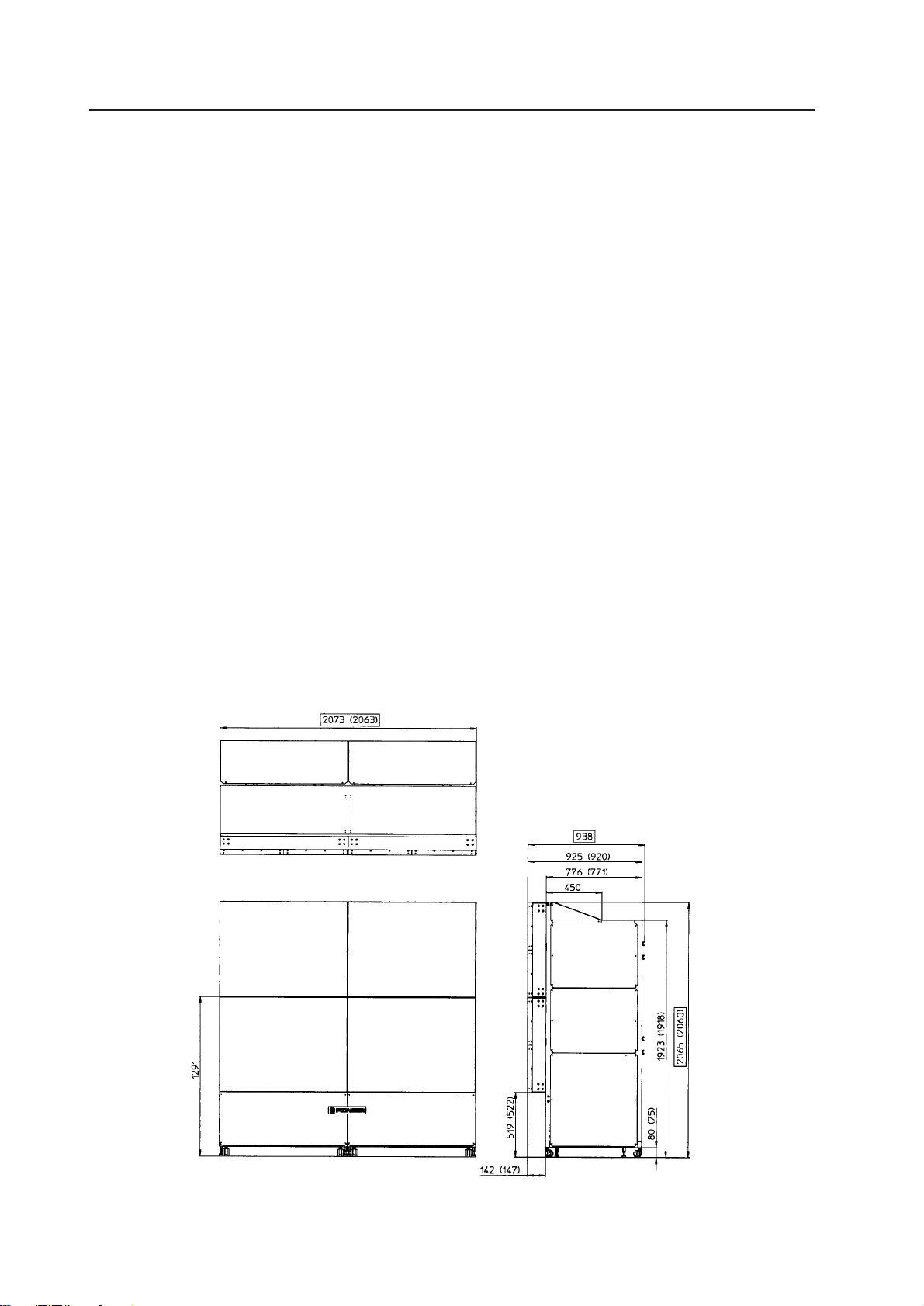
External dimensions
............................ 2073 (W)x2065 (H)x938 (D) mm
Weight ................................................. 403 kg (Total)
Unit R ........................................................... 177 kg
Unit L............................................................ 170 kg
Screen (x 4).................................................... 14 kg
Accessories
Mickey bolts ...................................................... x 8
Coaxial cable with connector
(no long discrimination tube) .......................... x 2
Coaxial cable with connector
(with long discrimination tube (orange)) ........ x 2
Coaxial cable with connector
(no short discrimination tube) ......................... x 2
Coaxial cable with connector
(with long discrimination tube (orange)) ........ x 2
Cable clamp (For connecting coaxial cable
with connector) ................................................. x 6
Cord with 6P mini DIN ...................................... x 3
Power cord ........................................................ x 2
Cable clip ........................................................... x 2
Screw ................................................................. x 2
Hexagonal bolt .................................................. x 3
Flat washer ........................................................ x 3
Spring washer ................................................... x 3
Logo sticker ....................................................... x 1
Scrivet (For screen) ......................................... x 28
Screw (For front panel:Spare).......................... x 8
Shield ................................................................. x 2
Shield S.............................................................. x 1
Scrivet (For shield) ............................................ x 6
* Amplifier speaker (Not incorporated)
Dimensions
1 Multi projection system
Each size includes the height of the head of attaching screws of the screen and ornamental
board, etc.
( ) indicates the size excluding the height of
the head of the attaching screws.
(Fig.2-1) unit : mm
6
Page 8
Page 9
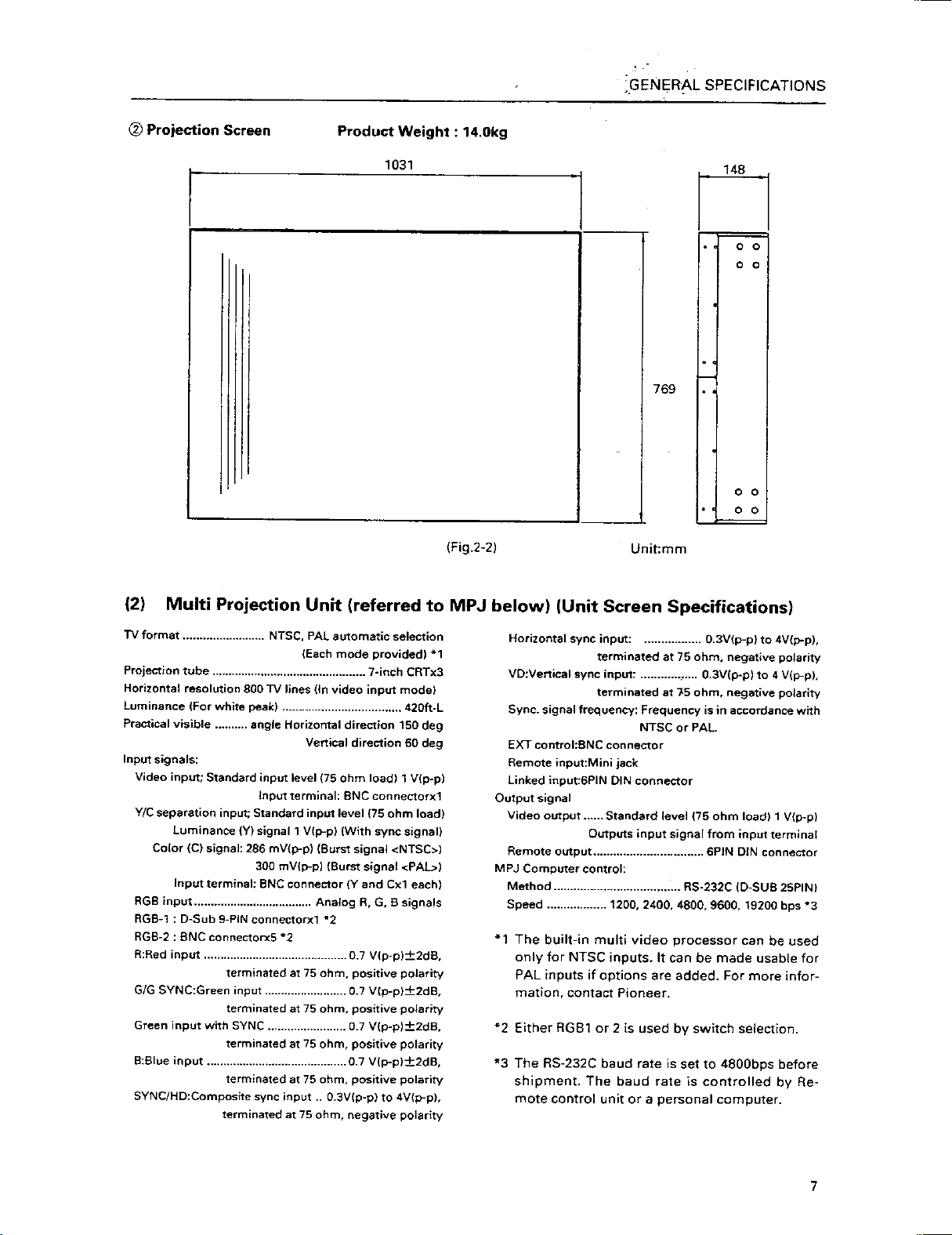
Page 10
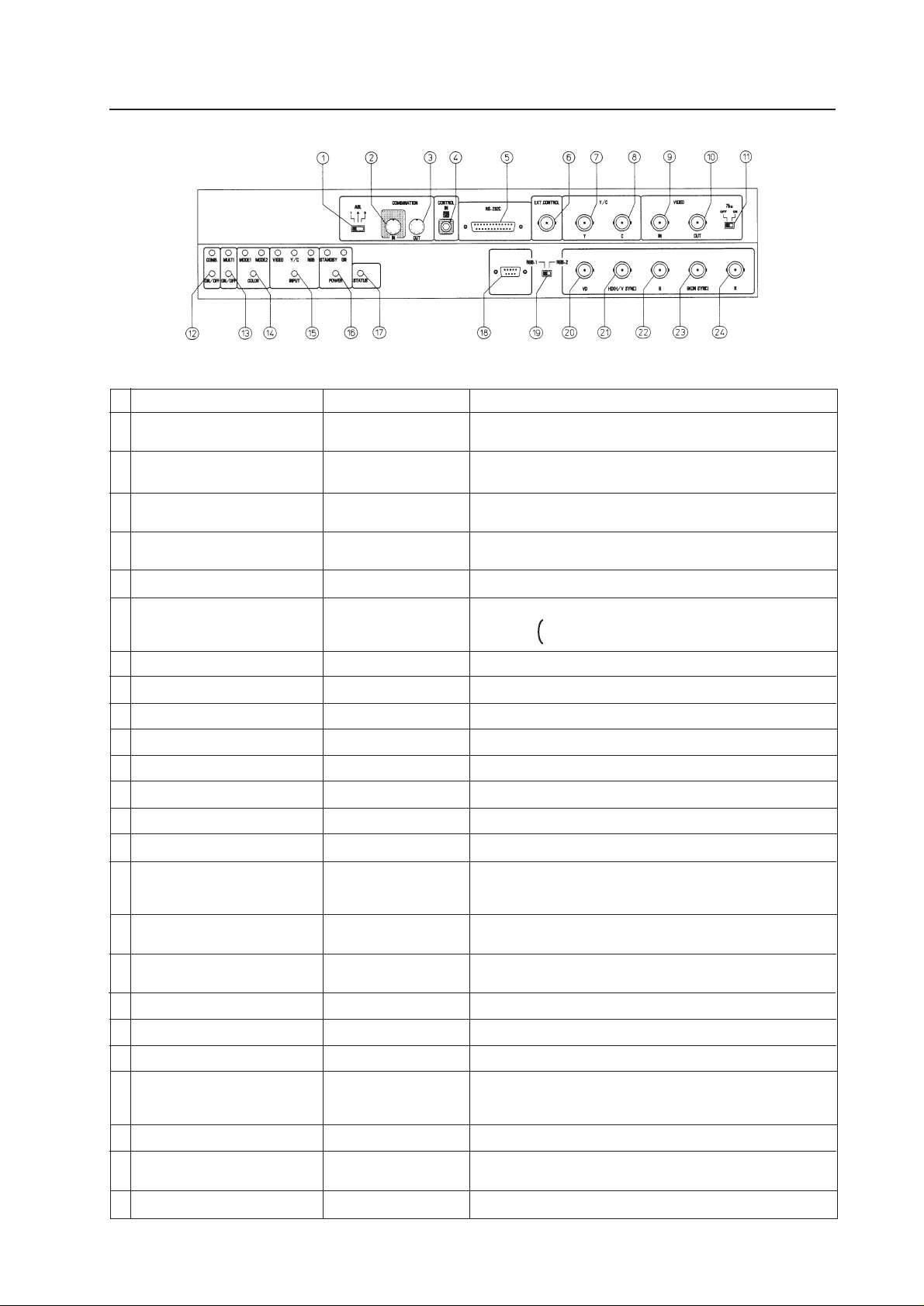
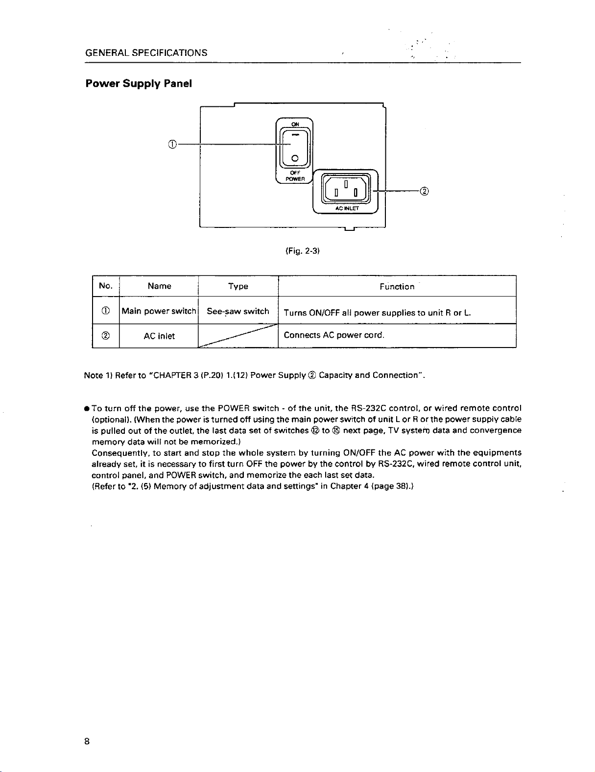
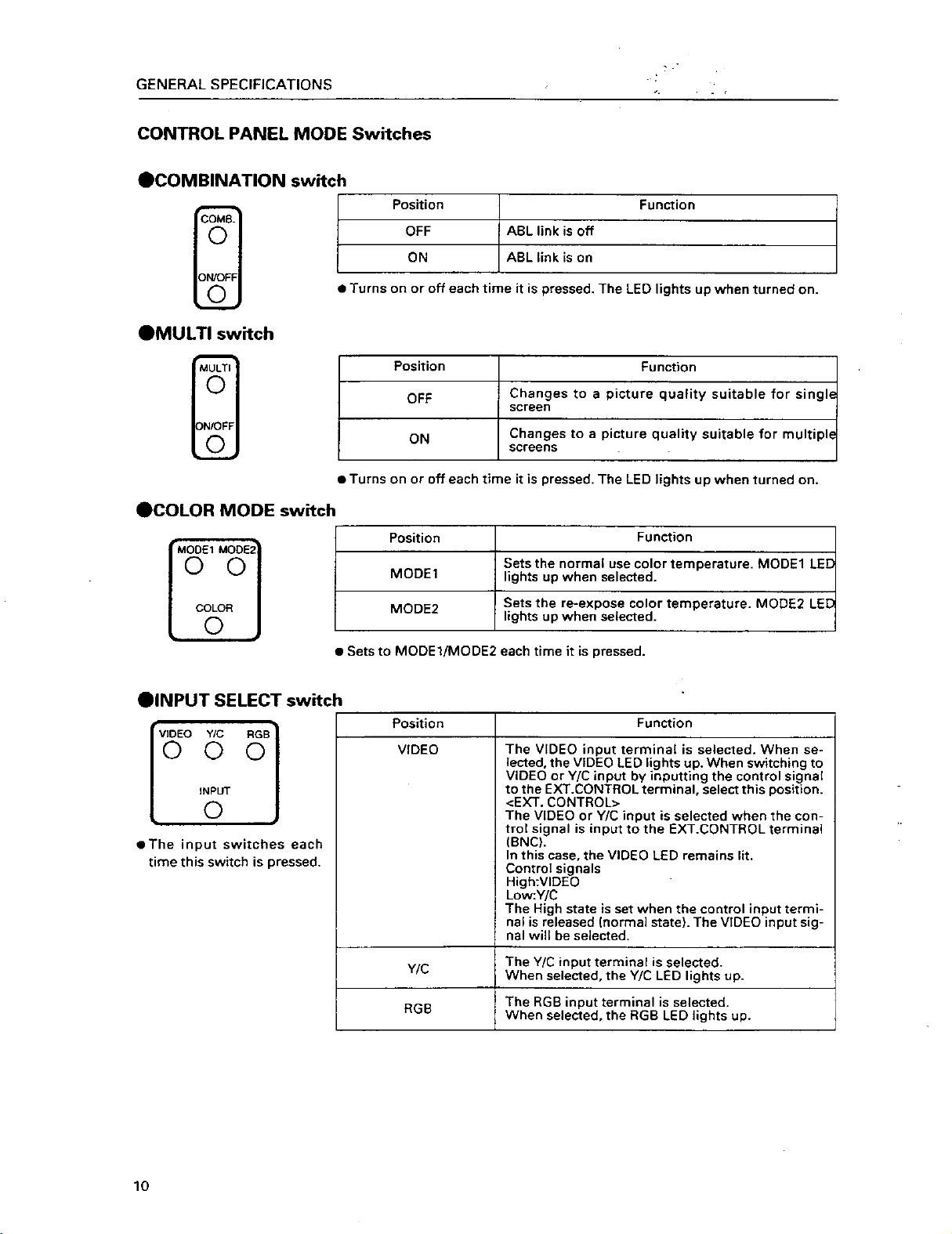
Control Panel
GENERAL SPECIFICATIONS
(Fig. 2-4)
No.
1
ABL link switch
2
Linked input terminal
3
Linked output terminal
4
Remote control connection terminal
5
RS-232C port
6
Control input terminal
7
Y (Luminance) input terminal
8
C (Color) input terminal
9
Video input terminal
0
Video output terminal
-
TERMINATE switch
=
COMBINATION switch
~
MULTI switch
!
COLOR MODE switch
@
INPUT switch
#
POWER switch
$
STATUS switch
%
RGB input terminal
^
RGB input select switch
&
RGB input terminal (Vertical sync)
*
RGB input terminal
(Horizontal sync/composite
sync)
(
RGB input terminal (B)
)
RGB input terminal
(G/composite sync)
_
RGB input terminal (R)
Name
Type
Slide switch
DIN 6PIN
DIN 6PIN
Mini jack
D-sub 25 PIN (Female)
BNC connector
BNC connector
BNC connector
BNC connector
BNC connector
Slide switch
Tact switch
Tact switch
Tact switch
Tact switch
Tact switch
Tact switch
D-sub 9PIN (Male)
Slide switch
BNC connector
BNC connector
BNC connector
BNC connector
BNC connector
Function
Used for switching the control level of the ABL link control voltage
when ABL link is ON.
Input terminal of ABL signal, remote control signal and RS-232C
signal
Output terminal of ABL signal, remote control signal, and RS232C signal
Connected to adjusting remote control (optional)
RS-232C communication connector (For MPJ control)
Video input and Y/C input external switching control signal input
terminal Normal(video signal input) : Open
Select Y/C input : Low(0V)
Luminance signal input terminal
Color signal input terminal
Video signal input terminal
Video input terminal 9 through-out terminal
Turns on when terminates the video input terminal 9 at 75 ohm
Turns on when linked to ABL
Turns on when used on multi screen
Switches the color temperature. 1:Normal use. 2:Re-exposure
Switches VIDEO input, Y/C input, RGB input.
Switches VIDEO input and Y/C input with the external control signal 6 at VIDEO position
Power OFF : STANDBY (Red LED) lights up
Power ON : ON (Green LED) lights up
Accumulated duty time * (P.11): Switch which displays setting
states of each switch on the screen.
RGB signal input terminal
Switches RGB signal input terminal type
RGB signal vertical sync input terminal
RGB signal horizontal sync and composite sync (Only for input
signal H/V sync) input terminal
RGB signal B input terminal
RGB signal G and composite sync (Input signal G on sync) input
terminal
RGB signal R input terminal
9
Page 11
Page 12

Page 13

(3) Multi Video Processor (Referred to MVP below)
GENERAL SPECIFICATIONS
Input signal
Input video signal (NTSC)
1-line ............................................. BNC terminal
(One RGB input system can be added with addition
of optional RGB board)
1 Composite video signal
...................... 1.0 V(p-p) (75ohm terminated)
2 Y/C separation signal
Y (With sync) ................... 1.0 V(p-p) (75ohm)
C burst level ................. 0.286 V(p-p) (75ohm)
* 1 or 2 signal format can be selected
3 Optional RGB input signal
RGB signal ........................0.7 V(p-p)(75ohm)
H.V ....................................................TTL level
C SYNC............. 0.3-4 V(p-p) (Negative logic)
Green (Sync on Green) ...1.0 V(p-p) (75ohm)
SYNC ...............................................0.3 V(p-p)
SYNC priority order
H.V > C SYNC > Green (Sync on Green)
RS-232C control input 25-pin D-SUB
Note 1
Output signal
Output video signal
4-line .............................................. BNC terminal
1 Composite sync signal .....1.0 V(p-p) (75ohm)
2 Y/C separation signal
Y (With sync) .................... 1.0 V(p-p) (75ohm)
C (With burst) Burst level
....................................... 0.286 V(p-p) (75ohm)
* 1 and 2 signal formats are output simulta-
neously.
3 RGB signal
Green (Sync on Green) ................... 1.0 V(p-p)
SYNC ................................................ 0.3 V(p-p)
B.R .................................................... 0.7 V(p-p)
Note 1: The built-in multi video processor can be made
usable for RGB and PAL inputs if options are
added. For more information, contact Pioneer.
12
Page 14
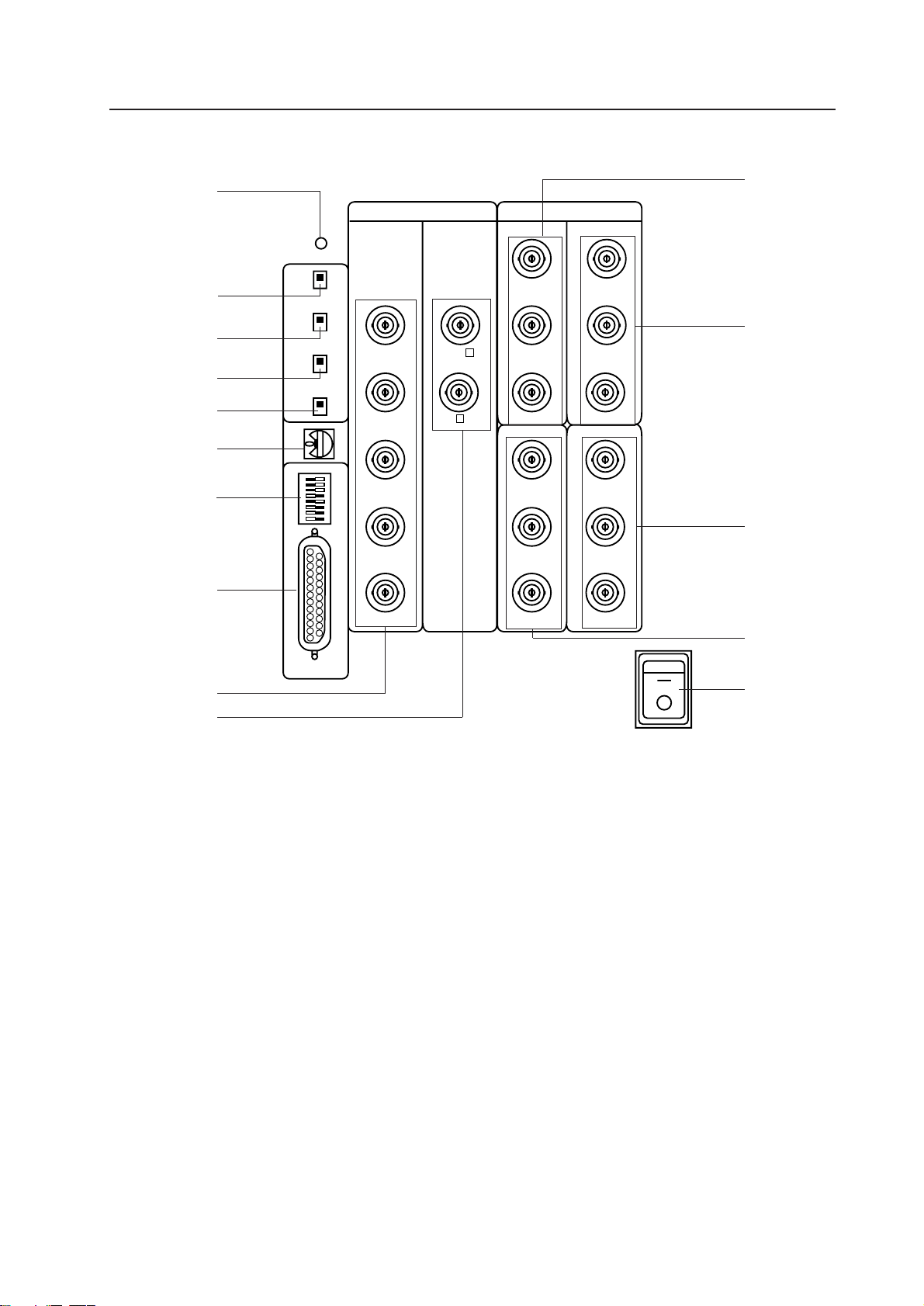
MVP Panel
GENERAL SPECIFICATIONS
2
3
4
5
6
7
8
9
RESET
GEN
LOCK
FILTER
MODE
RS-232C
RATE
EXT
INT
NTSC
RGB
ON
OFF
VBS
Y/C
INPUT OUTPUT
G VBS Y
B
R
H/C SYNC
VD
C
VOUT1 VOUT3
VBS/G
Y/B
C/R
VOUT2 VOUT4
VBS/G
Y/B
C/R
VBS/G
Y/B
C/R
VBS/G
Y/B
C/R
=
~
!
ON
@
0
-
1 POWER switch (Power)
Used to turn on/off the MVP power.
2 Reset button
System reset button. When this switch is
pressed, the system sets into the manual mode
and operates in the modes of the switches set
on the panel.
3 EXT/INT switch
Normally, this is set to the INT side so that the
MVP operates in the free-run mode for video inputs.
Leave it at the INT side unless when using the
MVP for special uses such as locking the MVP to
the video input.
1
OFF
POWER
4 NTSC/RGB switch
Select whether to set the NTSC input or RGB input to 4-screen magnification.
It is set to the NTSC side at shipment.
* When switching the switch, press the reset
button after switching.
* The RGB input is an option.
5 RGB input vertical filter on/off switch
Vertical filter on/off switch of optional RGB inputs. If the top and bottom of the RGB input image do not fit inside the output screen, turn on
this switch.
At shipment, it is set to off.
6 VIDEO/YC switch
Switch to set whether to input VIDEO or YC into
13
Page 15

GENERAL SPECIFICATIONS
7 MODE switch
Used to select the video output mode.
Output Mode Switch Contents
Switch
*2
0
1
2
3
4
5
6
7
8
9
A
B
C
D
E
F
Frequency
Mode
NTSC
NTSC
No.
*1
Standard speed horizontal frequency 15.734 kHz
Double speed horizontal frequency 31.468 kHz
*2
The switch is set to 8 at shipment.
Normally, use in the range from 8 to A.
Press the reset button when switching the mode.
Output Mode
Output
Mode
VBS,Y/C
RGB
RESERVED
VBS,Y/C
RGB
RESERVED
Standard Speed/
Double Speed
Standard Speed
Double Speed
Standard Speed
Double Speed
Trunk Piece
Mitigation Mode
*1
OFF
ON
9 RS-232C connector
For controlling MVP
0 RGB video input terminal (Optional)
Optional RGB input terminal.
G ..................... G signal input terminal of RGB
separation signal
B ..................... B signal input terminal of RGB
separation signal
R ..................... R signal input terminal of RGB
separation signal
H/C SYNC ...... H sync or C SYNC input terminal
V ..................... V sync input terminal
- NTSC video input terminal
NTSC input terminal
VBS .. Y signal input terminal of composite
video or Y/C separation signal
C ....... C input terminal of Y/C separation signal
= to @ Video output terminals 1 to 4
4-screen magnification video output.
VBS/G .... G signal input terminal of composite
video or RGB separation signal (Outputs G on SYNC during G signal output).
Y/B .......... Y signal output terminal of Y/C sepa-
ration signal or B signal output terminal of RGB separation signal.
C/R .......... C signal output terminal of Y/C sepa-
ration signal or R signal output terminal of RGB separation signal.
8 Baud rate switch
Used to select the RS-232C (For controlling
MVP) baud rate.
Baud rate selection switch (8 BIT DIP)
Functions of bit ........ Value at shipment
Switch No.
1
2
3
4
5
6
7
8
Baud rate set by switches No. 5 and 6.
SW1 -5 SW1 -6 Baud rate (bps)
ON ON 19200
OFF ON 9600
ON OFF 4800
OFF OFF 2400
* At shipment, 3, 5, and 8 are ON.
Switch function ON OFF
Parity yes/no Yes No
Parity polarity EVEN ODD
Character bit 8 BIT 7BIT
Stop bit 2BIT 1BIT
Baud rate setting See table below
RESERVED
RESERVED
Always use at off.
Always use at on.
The signals correspond as follows.
V OUT
Screen 1
V OUT
Screen 3
V OUT
Screen 2
V OUT
Screen 4
(Front View)
14
Page 16
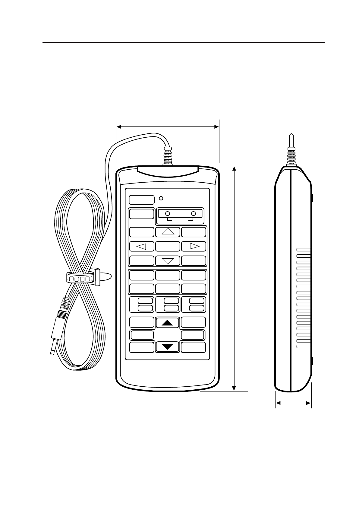
(4) Adjustment Control Unit (RU-V107) Option
84
GENERAL SPECIFICATIONS
POWER
0
13
46
79
D
ADJUSTMENT CONTROL UNIT
RU-V107
ADJ IN
2
5
8
Î
ABC
DEF
ADJ ADJ ADJ
RGB
ON/OFF ON/OFF ON/OFF
INPUT SEL
2
//
–+
DISP CALL
MAIN MENU
3
ADJ OUT
187
Cable length : 5m
(Fig.2-7)
Accessories
AA dry battery (IEC R6P) ..................................................................................... 2
Cable (5m) ............................................................................................................ 3
29
15
Page 17
CHAPTER 3. INSTALLATION AND ASSEMBLY
INSTALLATION AND ASSEMBLY
1. INSTALLATION CONDITIONS
(1) Weight-tolerant
The ground must be flat and horizontal. It should be able to bear the weight of the system.
For wooden floors, if the part receiving the weight of the system lies at the center between the reinforcement
beams below the floor, the floor may become deformed or may curve inwards. In such cases, lay a more than 12
mm thick board below the system to distribute the weight of the system on the floor.
For concrete floors, it may not be possible to install the system horizontally due to the roughness of the floor. In
such cases, do the same as above.
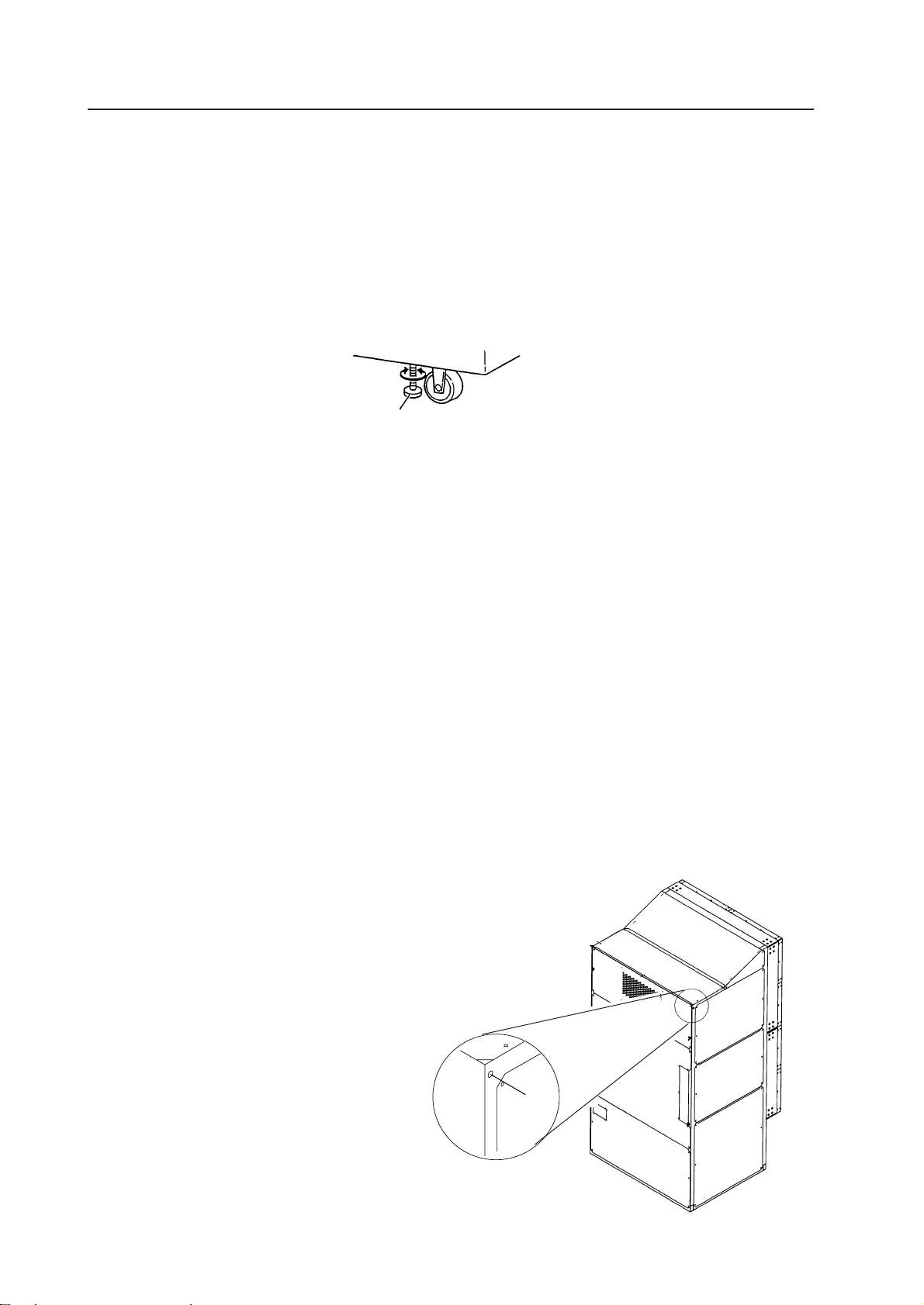
After installation, adjust and secure with the floor leveler.
Floor leveler
(2) Height to ceiling
¶ Leave about 30 cm between the top of the system and ceiling. Take note that if there are air-conditioner vents
or lights at the top, problems caused by dusts, temperature, humidity, and water drop may result. If adequate
space cannot be provided on the left and right sides, and at the back of the system, and the system is be
installed directly onto the wall, heat can only be discharged from the top. In such cases, be sure to provide
vents for discharging heat. Also observe the temperature and humidity conditions in (7).
(3) Front Space
¶ Finger and hand prints form easily on the face of the screen. Therefore make sure viewers cannot touch it
directly.
Leave workspace in front for replacing the screen.
(4) Rear Space
¶ At least 5 cm of space is required at the back of the system. However, leave more than 1 m at the back as
working space for the maintenance of the MPJ and MVP.
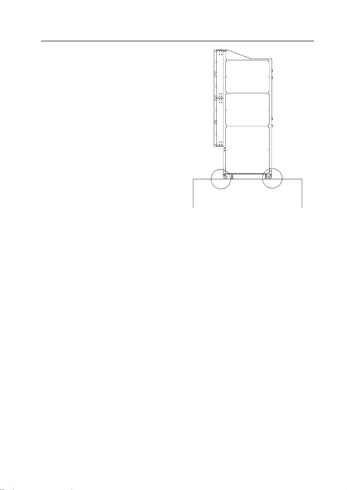
(5) Installation work for securing system
¶ After installation, always lower the floor levelers to prevent the system from turning over.
This system is also provided with holes to hook wires for preventing it from turning over. To prevent the
system from turning over, it is recommended that it be secured to the floor or wall.
¶ The method of securing to floors and walls differ according to their materials. Always have a construction
specialist or Pioneer dealer perform the procedure for you.
16
Page 18
(6) Installation work for mounting on
rack
¶ Blocking the front and back will cause heat to ac-
cumulate, which may result in malfunctions.
¶ Use a rack which can bear the weight of the sys-
tem.
¶ Take measures to ensure that the system does
not turn over. Always have experienced technicians or your dealer implement these measures.
INSTALLATION AND ASSEMBLY
(7) Temperature and Humidity Conditions
¶ Closely observe the following conditions on the temperature and humidity of the location of installation.
(1)Operating temperature : 5 to 35 degC (No condensation)
(2)Operating humidity : 20 % to 80 %
(3)Storing temperature : –10 to 45 degC
¶ The lenticular sheet will stretch and consequently the center of the screen will rise if the humidity is relatively
high. In this case, the focus may slightly change and therefore readjustments in the installing conditions of the
location must be performed when your system arrives.
¶ Avoid wetting the system at all times. Due to the shape of the product, it is easily affected by external condi-
tions. Especially to be avoided is wetting the MPJ and screen. Thorough water-proof measures must be taken
when installing them in locations where there is a high level of moisture in the air such as near air-conditioning vents and water sprays.
* Take note that in new buildings, moisture is frequently produced from the concrete and the humidity level
subsequently rises.
¶ Electrical equipment such as this system generally should not be installed in high humidity environments.
Follow the precautions below when high humidity is expected.
• Never install the MPJ and screen in locations that do not meet their respective specifications.
• Ground the units.
• Ensure that there is no condensation.
• Install the units where no one can touch them.
• Ensure that water droplets do not fall onto the units.
(8) Condensation
One problem that occurs in the winter season is “Condensation”. When the temperature of the room in which
this system is installed rises suddenly, condensation occurs on the screen and lens, thereby the system cannot
display its best performance. In such cases, turn off the power once, leave the system off for one hour, and turn
on the power again. Increasing the room temperature gradually is another method.
17
Page 19
INSTALLATION AND ASSEMBLY
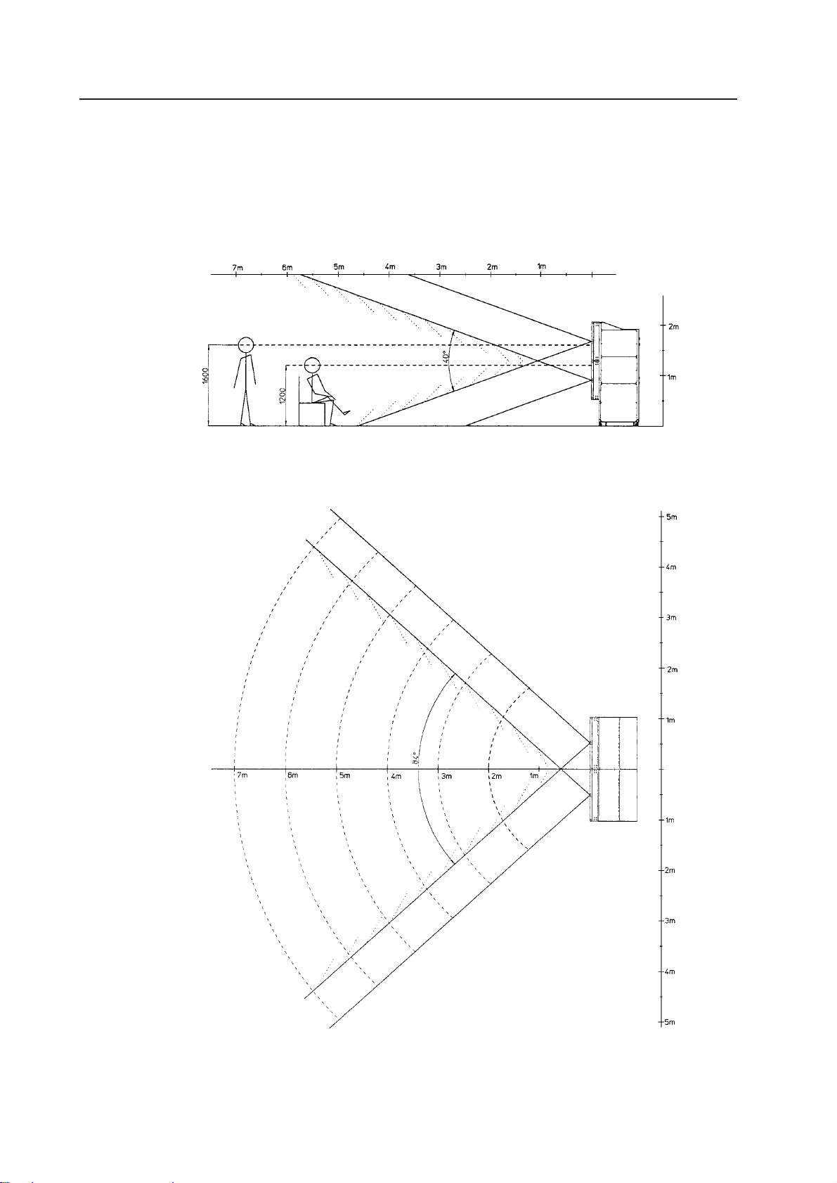
(9) Angle of view and appropriate view range
Vertical Visible Angle
(Fig.3-1)
Horizontal Visible Angle
18
(Fig.3-2)
Page 20

INSTALLATION AND ASSEMBLY
(10) Lighting
¶ Although reflection by external light as seen on CRTs will not occur with this projection screen, reflection may
result when strong light such as spot light is directed at the screen. Therefore, make sure that the screens are
not exposed to direct spotlight.
¶ For certain installation location conditions, a glass sheet may have to be attached to the screen surface. In this
case, as there will be reflection by external light, consider the installation position, etc. carefully.
¶ As the actual intended images of the system may not be obtained in very bright locations, consider the posi-
tion of lighting and direction of sunlight when installing the system. Especially when the system is exposed to
direct light (sunlight, etc.) from behind, the light may be reflected on the screen. Avoid such installations.
¶ Take note that in bright places, images may appear dark even when the luminance has been increased. In
addition, increasing the luminance and contrast more than required may affect the life of the system (especially the CRT).
(11) Effects of Earth Magnetism
¶ Due to effects of earth magnetism, the position of the image displayed will differ according to the installed
direction. Difference is about several mm in the up/down/left/right directions, but the degree of change varies
according to the strength of the earth magnetism of each area. Misconvergence may also occur due to slight
rotations.
Therefore, when performing adjustments before bringing the system into the installing location. Perform the
adjustments in the same direction and angle as installation, perform adjustments again at the final location
decided.
¶ If the system is used at a fixed position, adjust it at the final position used.
¶ The system is not only affected by earth magnetism but by the following magnetisms generated by various
items in its surrounding as well.
• Steel frame of building
• Power cables on the floor
• Large speaker systems
• Special equipment (Those generating magnetic force)
• Metallic installation table, frames, etc.
19
Page 21
INSTALLATION AND ASSEMBLY
(12) Power Supply
1 Power supply voltage
The guaranteed voltage of this system is ±10% of the rated voltage.
But if the impedance of the power wires is high, the voltage waveform will become distorted and show the same
symptoms as when voltage drops abnormally. As the following must be noted even if the voltage is within the
allowable range, check the power wiring again.
¶ The voltage drop from the switchboard to this system is great.
¶ The voltage changes greatly when the power of the system is turned on and off (Roughly 5% of the rated
voltage)
2 Power capacity and connection
This system is provided with one AC INLET each for units R and L. Referring to the current capacity below,
connect a switchboard with sufficient capacity for the left and right lines separately (the current increases when
the voltage drops).
When connecting the same line (same switchboard) to other devices, take note of the power consumption of the
other devices and make sure that the capacity of the switchboard is not exceeded.
Current Capacity
100 V 120 V
Unit R
(including MVP)
Unit L
(no MVP)
Power Capacity
940 VA 9.4 A 7.8 A
800 VA 8.0 A 6.7 A
3 Outlet Plug
The power supply cable of this system is provided with a outlet plug with grounding (2E) to prevent electric
hazards caused by current leakage.
Be sure to connect the plug to the outlet with grounding (2E).
4 Leak Breaker
The system is incorporated with the power line filter to reduce noise. For this reason, a leaked current of 2.0 mA
may flow through unit R (including MVP) and 1.0 mA through unit L (no MVP). If a current leakage breaker is
provided, check that the sensitivity current is above the total current leakage of the system.
Also calculate each unit such as image transmission unit, etc. as 0.5 mA.
Be sure to connect directly to the power supply on the cabinet panel to prevent voltage drop, deformation of the
current waveform, and noise inductance.
It is extremely dangerous to supply power from existing wall outlets, etc.
Install the system near the outlet for connecting the units of the system as much as possible.
Set the current capacity slightly greater-about more than 25% of the total consumption power.
20
Page 22

INSTALLATION AND ASSEMBLY
(13) Cables Used
Use a coaxial cable for the external input cable. Normally use a 3C-2V for less than 15m long. Use 5C-2V for
greater lengths. Adjust the length of the cables. The distance between the transmission system and MPJ should
be as short as possible. When the distance is great, consider the thickness of the cable and electrical compensation carefully.
The limit is as shown when using the cables to connect the transmission final output terminal and the system.
3C-2V: 15m
5C-2V: 30m
To use a longer cable, the VIDEO signal must be corrected.
(14) Semi-outdoor Installation
This system is basically designed for use indoors. When the system is installed in semi-outdoor locations, the
following problems may occur. Take the following measures before using the system.
• Waterproof and rustproof measures
• Temperature difference and humidity difference
• Light on the screen (So that it is not exposed to direct sunlight.)
• Wind containing salt
21
Page 23

INSTALLATION AND ASSEMBLY
2. INSTALLATION AND ASSEMBLY
(1) Confirmation
1 Decide the position for installing the system according to the installation conditions in Chapter 3.
Check Items
[1] Dimensions of installing position, space at the back, distance to the ceiling
[2] Floor flatness, strength, roughness
[3] Position of power supply
[4] Installing location
Need for protection for the floor, walls, etc. (support covers, sheets, cover boards, etc.), width of the areas
and paths used for moving the system in and out, if elevators are used, its size and weight limit, etc.
[5] Position, specifications, and structure of a transmission equipment, and image type
[6] Model number of equipment used, and their quantity (perform according to list).
Check if there is enough equipment for each unit
* These procedures must be performed by only one person.
(2) Opening the Packaging
1 Packaging specifications
[1] Projection Screen Kit (×4) : 1126(W) × 230(H) × 879(D)mm 20.2kg
[2] Unit(×2) : 2225(W) × 1200(H) × 1105(D)
Unit R : 310kg
Unit L : 303kg
2 Opening the packaging
Open from the big ones first and put the small packagings inside the empty big packagings. Also dispose or
store the packagings.
Do not mix up the opened items with those still in the packaging.
Move the empty packagings somewhere else so that they will not come in the way. Next, obtain an assembly
space that is as wide as possible.
* Turn down the opened packagings upside down to differentiate them from those not opened.
Do not lose accessories, the warranty card, etc.
22
Page 24
INSTALLATION AND ASSEMBLY
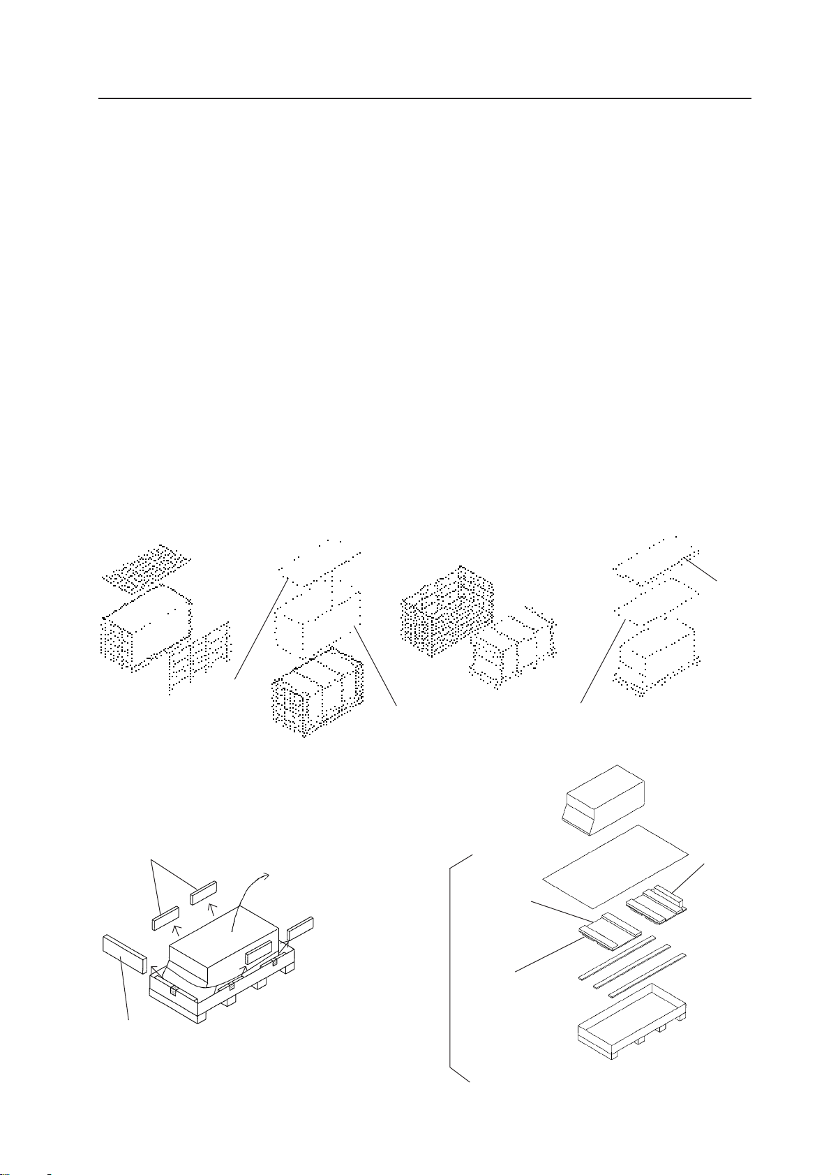
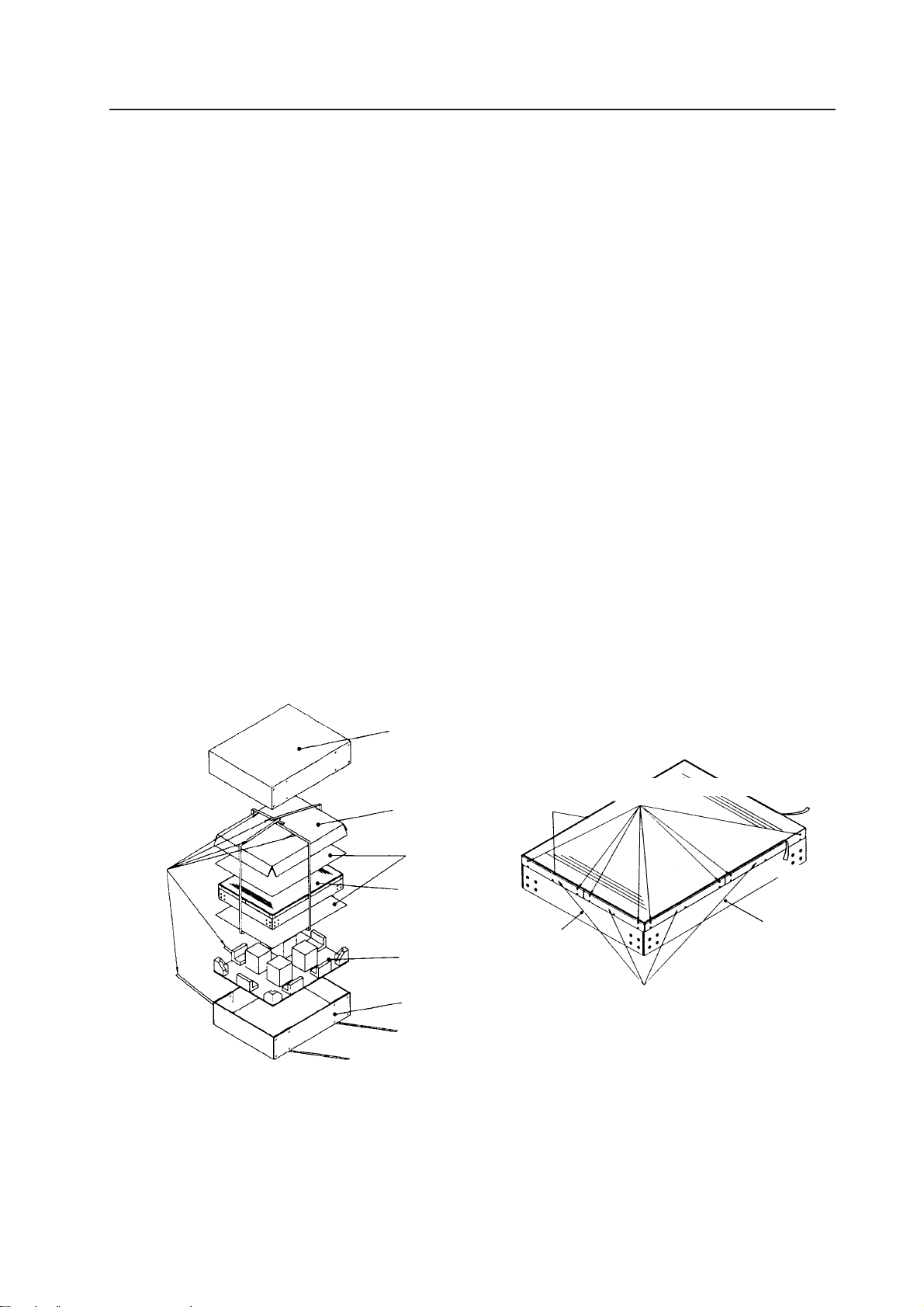
3 Unpacking
[1] Remove the top and side (the longer side) wood frames one by one.
[2] Remove the upper cover and side cover.
[3] Remove the unit from the frames.
[4] Remove the upper pad and mirror mat.
[5] Remove side pad, and top pad covering the unit.
Remove the tapes for transportation protection. (Six in each unit)
[6] While paying attention to the top and bottom of the unit, place the unit upright together with the under
carton. (This should be done by more than 3 persons.)
[7] Remove the under carton.
[8] Remove the engine pads A and B, engine side pad, engine side pad F, bottom mirror pads A and B, top
mirror pads A and B, mirror mat (3 each at the top and bottom), MVP pad, lens protector paper, and CRT
cover. (Remove engine pads A and B using a cutter knife, etc.)
[9] Attach the Mickey bolt to pad A and the shield to top mirror pad A, and the other accessories to bottom
mirror pad B.
[1]
Upper cover
[5] [6]
Side pad
[2] [3]
Direction to pull up
Side cover
[4]
Upper pad
Mirror mat
[7]
Pad B
Mickey bolt
Top pad
Under carton
(Fig.3-3-1)
Pad A
23
Page 25
INSTALLATION AND ASSEMBLY
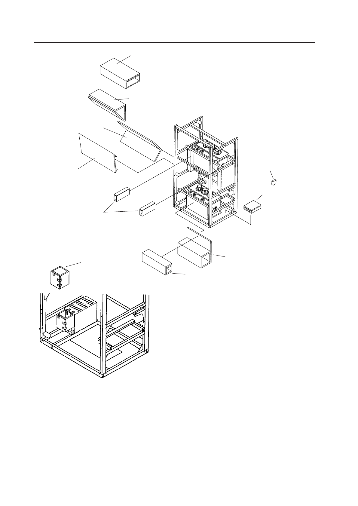
[8]
Bottom mirror pad A
Bottom mirror pad B
Engine side pad
Top mirror pad B
Top mirror pad A
Mirror corner pad
Engine side pad F
MVP pad
Engine pad A
Engine pad B
(Fig.3-3-2)
24
Page 26
INSTALLATION AND ASSEMBLY
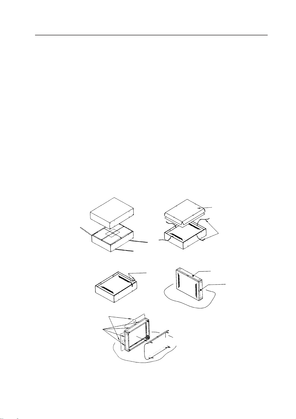
4 Projection Screen
* Projection screen is double-packaged to maintain its performance. After removing the middle cover protect-
ing its screen, make sure the screen does not get scratched or dirty.
[1] Remove the top cover.
[2] Remove the band securing the middle cover and remove the middle cover.
[3] Gently peel off the black tape pasted at the four sides of the screen.
* Be careful not to damage the lenticular sheet.
[4] Take out the screen unit from the box and stand it on a flat floor, paying attention to its top and bottom.
[5] Remove the eight screws for transportation (gold), four protection panels and white sheet at the back of
the screen.
* The protection panel is attached with the transportation screws. Keep the removed panel if required.
When storing the system, do not remove the outermost protection panel.
[6] When opening the packagings of several units first, after opening them, place them in a different place to
protect them from damage, and place a sheet over them to protect them from dusts.
[1]
Top cover
[3]
Transportation screws (Eight : Gold)
Protection panel
Black tape
[2]
[4]
Middle cover
Band
Top
Right side
Flat floor
[5]
White sheet
(Fig.3-4)
25
Page 27
INSTALLATION AND ASSEMBLY
2
2
2
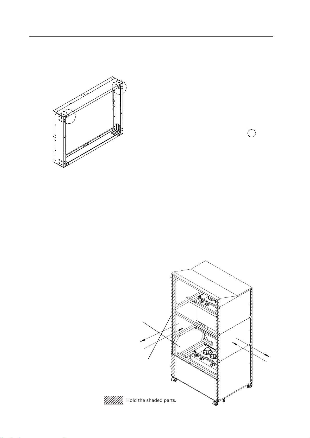
(3) Carrying the Units After Opening Packaging
1 Screen
To carry the screen unit after opening the packaging, hold them by the parts shown in the figure, and lift and
move them.
(Lifted by one or two persons)
Hold the parts indicated by
(Fig. 3-5)
¶ Never drag the system along the floor when moving the units.
¶ The lenticular sheet damages very easily as it is very thin. Therefore move it gently and do not apply excessive
shock or vibration to it.
¶ As the panels supporting the screen are very thin and deform easily, be careful that they do not hit or get
hooked onto surrounding objects when moving them.
2 Unit
¶ When moving the unit, push the frame (square) without pushing the rear panel. Never push to the front or
back.
¶ Do not move the system on casters on rough places such as tiles and bricks.
¶ Do not move the system after installation.
2345678901
2345678901
2345678901
Hold the shaded parts.
26
Page 28
INSTALLATION AND ASSEMBLY
3. PRECAUTIONS FOR TRANSPORTATION
Do not stack the units on their sides or backs when transporting them.
Always place them upright. If they are stacked on their sides or backs, vibration and shock may cause damage or
fire hazards.
7 Precautions on transportation of unit
¶ Because it damages easily when dropped, exposed to shock or vibrations, be careful not to place heavy
objects on the unit nor drop it in transportations.
¶ Always place the unit on its side, never upright, in transportation.
¶ Do not place objects on the unit when storing it due to the simple packing.
7 Precautions on transportation of projection screen
* As Projection screen must always be installed, it will not need to be re-packed and transported. Packaging
instructions are provided for your reference just in case it has to be transported again.
¶ Pack it properly according to the packaging specifications (Fig.3-6). Also check the following conditions.
[1] The protection panel has been properly attached by the transportation screws (eight).
* Use the protection screws (gold) provided with the unit.
[2] The protection tapes are pasted to the four corners of the protection panels.
* Paste the protection tape on the protection panel.
* Use a relatively weak tape about 20 mm to 30 mm in width.
<Recommended Tape>
Name :Acetate cloth adhesive tape (25 mm width)
PP bands
Upper carton
Top pad
Mirror mats
Projection screen
Bottom pad
Under carton
(Fig.3-6)
Transportation screws (Eight, gold)
Protection tape
Right side
Protection
tape
Protection
tape
Top side
Protection panels
27
Page 29

INSTALLATION AND ASSEMBLY
¶ When transporting or storing the units in the packaged state, always face them up.
¶ The number of units that can be stacked in storage is 16.
¶ As the screen is at the top, be careful not to step, and place heavy objects on this top side, nor hit it with sharp
objects.
<Note>
Do not mistake the top and bottom of the screen unit. The side with the longer screw projecting out (side with
transportation screw) is the top and the side with the 8 mm hole is the bottom.
Before mounting the screen unit to this system, check that the transportation screw, protection panel, and
black tape have been removed. (Do not remove the protection panel on the outer-most side when installing
the system.)
Also tighten the Mickey bolts used for connecting the unit and screen unit together using your hand. Tighten
as firmly as possible.
Put on gloves when stacking the screen units for protection and perform in twos.
To prevent the lenticular sheet from damage, mount the screen unit gently and do not subject it to vibration
and shock.
When the screen units are stacked, the head of the panel fixing screws and 8 mm holes will engage. When
stacking the upper screen unit, make sure that it does not brush the lower screen unit as it has panel screws
projecting out.
28
Page 30
INSTALLATION AND ASSEMBLY
4. ASSEMBLING THE SYSTEM
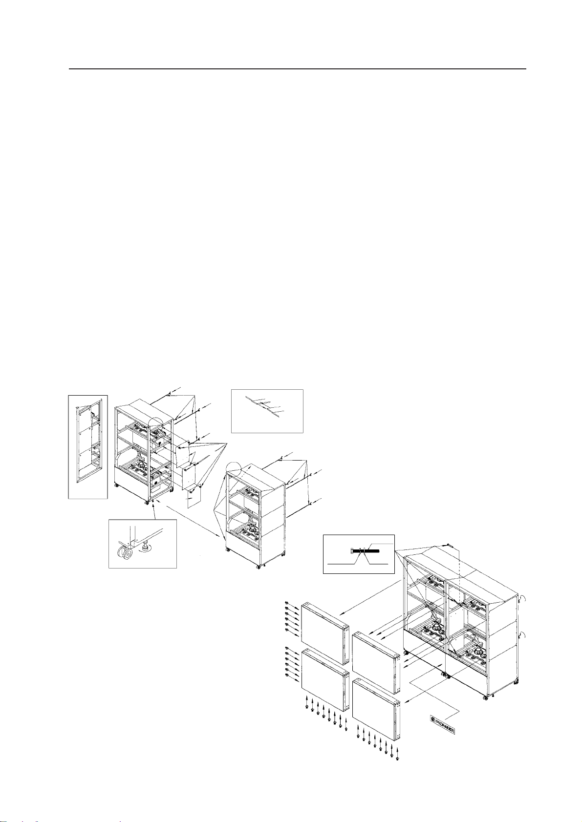
(1) Assembling the system
[1] Before moving the system to where it is to be installed, insert three Mickey bolts into the main unit.
[2] Secure the shield and the shield S to unit L with the scrivet (six parts).
[3] Move units R and L to the place where the system is to be installed.
Move the units closely together, adjust so that the levels of their frames are equal using the floor leveler,
and adjust the guide pins in front and back to the holes. (Four) Pay attention to the sides of the upper panel.
[4] Tighten units R and L using the hexagonal bolts (two in front and one at the back) containing the spring
washers and washers.
[5] Mount one screen at a time from the bottom.
Place the screen on the front panel, and then while one person holds the screen in front so that it does not
turn over, another person attaches the Mickey bolts from the back. (two parts)
[6] The screen should be mounted by two persons as above.
[7] Attach the scrivets at the left side (12 parts) and bottom side (16 parts) of the screen.
[8] Paste the logo sticker on the front panel.
[1] [2] [3]
Mickey bolts
Attaching
the shields
A
Shield S
Floor leveler
Shield
Guide
pin
Sides of the
upper pannel (A)
Scrivet (for shield)
A
Scrivet
(for screen)
Mickey bolts
[4] [5] [6] [7] [8]
Spring
washer
Screen
Hexagonal Bolt
washer
(Fig.3-7)
Scrivet
(for screen)
Logo sticker
29
Page 31

INSTALLATION AND ASSEMBLY
(2) Inserting the Option Board (MVP)
[1] Remove the rear cover C (R) and rear cover C (L). (Six screws for each)
[2] Remove the UL cover A. (Six screws)
[3] Remove the UL cover C. (Two screws)
[4] Disconnect the MVP power cord.
[5] Disconnect the connector and remove the power supply. (Three screws)
[6] Remove the four screws in front of the MVP.
[7] Tilt the MVP slightly, and pull it out.
[1]
Rear cover C (R)
[2] [3] [6] [7]
[4] [5]
Rear cover C (L)
Pull in this direction
30
UL cover C
UL cover A
Page 32

INSTALLATION AND ASSEMBLY
[8] Remove the bonnet. (Fig. 3-8)
10 screws
[9] Remove the rear cover. (Fig. 3-9)
9 screws
Loosen the six screws (ABA-283).
[10] Push in the optional board completely inside the second rail from the right. (Fig. 3-10)
[11] Attach the rear cover. (Fig. 3-11)
11 screws
Tighten the six screws (ABA-283)
[12] Attach the bonnet. (Fig. 3-12)
10 screws
(Fig.3-8)
(Fig.3-10)
(Fig.3-11)
(Fig.3-9)
(Note)
To prevent damages of the optional board resulting from static electricity, touch the bonnet, etc. before touching the board to remove
static electricity in the body.
(Fig.3-12)
31
Page 33

INSTALLATION AND ASSEMBLY
(3) Connection
Accessories
¶Coaxial cable
Black
Orange
260
130
A B C D E F
OrangeBlack
¶Linked cable 6P mini DIN cord
Connect as shown in Fig. 3-13 using the
cable provided.
After connecting, secure with a cable
clamp. (Fig. 3-14).
Linking cable (Cord with 6P mini DIN)
Remote control unit
(Note)
When connecting the RS-232C communication connector and remote control unit from
the leftmost (as seen from the back), connect IN and OUT linking cables (cords with
6P mini DIN) the other way around.
RS-232C communication connector
(Fig.3-13)
32
(Fig.3-14)
Cable clamp
Page 34

INSTALLATION AND ASSEMBLY
Examples of System
(1) Enlarged display only
LDP
C.VIDEO
To MVP input
(2) Multi display
LDP 1
LDP 2
LDP 3
LDP 4
Matrix SW
RS-232C
RM-V1000NU/
RM-V1000NA
To C. VIDEO MPJ input
To C. VIDEO MPJ input
To C. VIDEO MPJ input
To C. VIDEO MPJ input
To C. VIDEO MVP input
Personal computer
for control
LDP 1
LDP 2
LDP 3
LDP 4
RS-232C
C.VIDEO
To MVP
input
SW or selector, etc.
5
5
To each MPJ
MVP
RGB input
To MPJ
RM-V1000NU/
RM-V1000NA
5
5
Switching of Displays
¶ Enlarged display 1 Select the signal displayed by the matrix SW, and send the signal line to the
MVP.
2 Set the MPJ input to RGB.
¶ Multi display 1 Select the signal displayed by the matrix SW, and send the signal line of the
MPJ.
2 Set the MPJ input to C. VIDEO.
5. SPECIAL INSTALLATION
(1) Wall inset
¶ When fixing the screen into the wall, leave space at the top, bottom, left and right sides for attaching and
removing the screen.
(2) Diagonal installation
¶ This system cannot be placed facing upwards or downwards and diagonally. Always place it horizontally.
(3) Architrave processing
¶ When enclosing the screen with a frame, etc., add 15 mm
to the dimensions of the assembled screen at the top, bottom, left, and right. (Fig.3-15)
* Perform framing constructions after assembling the
screen.
¶ If light leaks from the rear space after constructions, place
a blind plate over the rear.
(4) Upside down installation
¶ Not possible
(5) Hanging from ceiling
¶ Not possible
15 mm
15 mm
(Fig. 3-15)
15 mm
15 mm
33
Page 35

Page 36

(5) Equipment Required for Adjustments
The following are required for the adjustments performed during the set-up of MPJ.
ADJUSTMENTS
Equipment
Personal
Computer
Adjusting
remote
control
Signal
generator
Adjusting LD
LD player
Cable
Adjusting LD
Role
For adjusting
For adjusting
For generating
white balance
and color tint
adjusting signals
Total image
quality adjustment
For playing adjusting LD
For connecting
RS-232C
For connecting
video
For generating
signals for adjusting size, convergence
Required Function
RS232C communication
function
Gray scale
White (% variable)
High definition image
Picture of beauty
Various adjustment signals
With still function
D-Sub 25-pin (male)
straight cable
Monoscope
Crosshatch
Recommended
Model
Pioneer
RU-V107
LD
demonstration
2 (Not for sale)
Pioneer
LD-V4400
Test disc
GGT 1072
Remarks
Prepare a Personal Computer or
this remote control for adjustment.
Especially white (% variable) is
important.
(Cannot replace with LD, etc.)
Use signal generators of this class
at the least.
Perform color, or final and overall
adjustments with the actual images.
The length differs according to the
place adjustment is performed at,
but prepare at least 10 m.
Use for adjusting screen size and
center.
35
Page 37

Page 38

ADJUSTMENTS
(2) TV System
The TV system determines the control of the whole unit (convergence, OSD display select, video system select,
deflection) according to the signal input.
Set it according to the signal input.
When TV SYSTEM is set to AUTO
¶ The mode is automatically set to NTSC or PAL according to the input signal (NTSC/PAL).
When the TV SYSTEM is set to NTSC
¶ The mode is set to NTSC regardless of the input signal.
When the TV SYSTEM is set to PAL
¶ The mode is set to PAL regardless of the input signal.
[Precaution to use]
Normally, the TV SYSTEM is set to AUTO. If the signals cannot be differentiated between NTSC and PAL (or they
are differentiated incorrectly : VCR signal repeatedly dubbed or part of CATV converter, etc.), the TV SYSTEM is
set to NTSC or PAL according to the input signal.
When the input signal is NTSC or PAL, and the TV SYSTEM is set to NTSC or PAL, it can enable the input to be
switched smoothly (little screen noises), and prevent signals from being differentiated incorrectly due to signal
disturbances and cuts.
In some cases, even if the same TV format is used, more than two types of convergence data will be required.
(For example, when there are signal phase differences for every input source, etc.) In such cases, use two types
of memories. Switch them using the personal computer.
(Note)
The built-in multi video processor can be used only for NTSC inputs. It can be made usable for PAL inputs if
options are added. For more information, contact Pioneer.
37
Page 39

Page 40

ADJUSTMENTS
(6) Giving IDs
IDs are used to differentiate the MPJs. When the units are given IDs, by connecting the ABL link cable, commands can be transmitted by specifying the ID, and it is possible to operate only MPJ corresponding to that ID
by remote control operations.
(Note) The following IDs are provided at shipment.
Screen 1
ID=11
Screen 3
ID=13
Unit L
<Giving IDs using Personal Computer>
Commands: IDC (IDC CLEAR) ;Clears the ID given
IDS (ID SET) ;Gives an ID
The IDS is valid only when no ID has been given. It will be valid from MPJ nearest to the personal
computer (remote control).
(Example)
4 screens (When providing IDs again using the personal computer after clearing all IDs set at shipment.)
Screen 1 OUT IN Screen 3 Screen 2 OUT IN Screen 4
Personal Computer
**AJY
11 IDS
↓
**AJY
13 IDS
↓
**AJY
12 IDS
↓
**AJY
14 IDS
Multi Projec-
tion Unit
ID=11
Screen 2
ID=12
Screen 4
ID=14
Unit R
Multi Projection Unit
ID=13
OUT IN
Multi Projection Unit
ID=12
Multi Projection Unit
ID=14
By sending commands in this order, IDs can be given to each MPJ (connect ABL link cables as above example).
The characters that can be used for the IDs are 0 to 9 and A to F, and * (capital and small letters are not differentiated).
The * can be used in the following way.
** IDC :Clears IDs given to all units
*1AJY :Only MPJ which have IDs whose 2nd digit is 1 enter the adjustment mode.
2* IN1 :The input function of only MPJ which have IDs whose 1st digit is 2 is set to VIDEO.
39
Page 41

ADJUSTMENTS
1
9
ADJ IN
Using the Remote Control>
[1] Press the
[2] The main menu will be displayed. Press the
Select “1. ID SET/CLEAR/SELECT”
[3] Check that the ID display at the top left of the screen is “– –” and press the
Select “1.ID SET”.
If an ID has already been given, press the
“[1] Enter the adjustment mode.” and give the ID.
[4] As the ID input standby state is set, press the
[5] To use the multi-screen MPJ, return to “[1] Enter the adjustment mode.” and given an ID to the next MPJ.
(Note) To return the whole screen to the main menu after giving IDs to the whole screen, press the
<Selecting the ID Using the Remote Control>
Select the screen to be adjusted using the remote control.
(Example) Select the ID at the bottom left side of the screen (ID=13)
[1] Set all screens to the adjustment mode using the
[2] Select [1. ID SET/CLEAR/SELECT using the
[3] Select [2. ID SELECT] using the
[4] Press the
[5] Only the bottom left side of the screen shows the main menu. The other screens will set into the standby
state (
ADJ IN
key to set the whole screen into the adjustment mode.
as shown in the figure on the right.
key.
2
POWER
and
2
,
ADJ IN
1
keys (ID=13).
ADJ OUT
,
keys only are accepted).
1
key.
key.
key, select “0. ID CLEAR” of the main menu, return to
0
to
0
,
to
A
keys, and input the ID.
F
ADJ IN
ID = 12ID = 11
ADJ IN
key .
1
key.
ID = 13
ID = 14
At shipment
key.
¶ To return to the main menu after completing ID SELECT, press the
Pressing the
key will also return to the main menu, but it also clear the ID SELECT state, making it
MAIN MENU
key to keep the ID SELECT state.
necessary to repeat from step [1] again.
To select other screens, press the
MAIN MENU
key to return to the main menu, and change the ID number set at
step [4] above.
(Note) : When the wrong ID has been specified
Repeat the above steps [1] to [5]. Perform the same steps when an inappropriate ID (Example : ID=33, etc. in the
above screen) has been input. In this case, all screens will set into the standby state.
<Precautions for Giving IDs using the Remote Control and Personal Computer>
Communication cannot be performed with units connected using the ABL link cable, after units whose IDs
have been cleared. When the command “** IDC” shown in the figure on the previous page is performed, only
the first unit can be controlled. Using the command “11 IDS” will enable the 2nd unit and onwards to be
controlled.
When IDs are set as this, the unit connected next can be controlled.
40
Page 42

Page 43

ADJUSTMENTS
3. SCREEN ADJUSTMENTS
(1) Adjustment Flowchart
The following shows the order for performing the adjustments generally required in the setup of this system.
For details, see the descriptions on the next page and later.
1 Give ID
↓
2 Adjust the size of each screen
↓
3 Adjust the convergence of each screen
↓
4 Adjust the joining of the screens
(Adjust the MVP. Refer to “Appendix (MVP Manual)” in Chapter 7 (page 103).)
↓
5 Check that there is no information missing and color deviation on the moving image.
If information is missing or color has deviated, return to 2 and readjust.
↓
6 Adjust the white balance of each screen.
↓
7 Adjust the ABL level
↓
8 Check the ABL level and white balance using the video actually transmitted.
If there is deviation, return to 6 and readjust
↓
9 Adjust the color tone using the video actually transmitted.
↓
0 Recheck 6 to 8
42
Page 44

(2) Convergence Adjustment Flowchart
ADJUSTMENTS
1
(P. 44)
2
(P. 44)
3
(P. 44)
4
(P. 45)
Find the center of the screen
Input the adjustment signal
Using only green, adjust the
center of V STATIC GH STATIC
Adjust the size of V SIZE V␣ LIN
H␣ SIZE GH LIN
Is the Horizontal size
standard (93%)?
YES
NO
8
(P. 59)
Adjust H BLK-L and
H␣ BLK-R
5
(P. 46)
6
(P. 46)
7
(P. 46)
Adjust joining of peripheral screens
in green point convergence mode
Adjust linearity of green point convergence mode
Adjust green, red, blue color deviation
in point convergence mode
43
Page 45

ADJUSTMENTS
(3) Convergence Adjustment Contents
1 Measurement of screen center
The center can be found easily by pasting threads in
the spaces of the protection panels at the screen
frame.
2 Adjustment signal input
& numbers correspond to the numbers in the
The
flow-chart.
For adjusting size ..................................................... Frame size picture(EX.LD Test disc GGT1072, FRAME No.
5941),Monoscope, etc.
For screen joining, linearity, color adjustment. ..... Use adjustment signals such as , cross-hatch, etc. (EX. LD
Test disc GGT1072, FRAME No. 7081,etc.)
(Note)
For the particulars about the FRAME No.,etc. of LD Test disc GGT1072,refer to the disc manual differently.
3 Center adjustment
Center
Set to only green and adjust the center with
V STATIC GH STATIC␣ .
V STATIC
44
GH STATIC
Page 46

ADJUSTMENTS
4 V SIZE, V LIN, H SIZE Adjustment
1 V SIZE adjustment
Set to only green, observe the top part of the screen ,
and adjust the data amount in the vertical direction using V SIZE .
Do not observe the bottom part of the screen.
2 H SIZE adjustment
Observe here
Set to only green, observe the right side of the screen ,
and adjust the data amount in the horizontal direction
using H SIZE .
Do not observe the left side of the screen.
3 V SIZE, V LINEARITY, H SIZE, GH LINEARITY adjustment
Those familiar with the convergence adjustment can adjust the bottom part of the screen in addition to the
top part of the screen using V SIZE and V LINEARITY . Also it can adjust the left side of the screen in addition
to the right side of the screen using H␣ SIZE and GH LINEARITY .
Observe
here
Reference Information
To adjust the NTSC input for horizontal 93% and vertical 92%, use the frame size screen of the LD test
disc GGT1072 (frame No. 5941).
Horizontal : Adjust so that the sixth 92.5% line from the inside can be seen completely.
Vertical : Adjust so that the sixth 92.5% line from the inside can be seen only slightly.
45
Page 47

Page 48

ADJUSTMENTS
Movement of screen by point convergence adjustment
Movement of screenOSD display
Observe here
Use especially when adjusting the horizontal size of the left side of the screen␣ .
In addition, there are nine other area adjustments. It is a convenience to adjust deviation of circumference
screens.
47
Page 49

ADJUSTMENTS
48
Page 50

ADJUSTMENTS
49
Page 51

ADJUSTMENTS
In adjustment step 5 , observe the external part of the screen, adjust the 16 adjusting points there, taking note
of linearity in the peripheral area such as joining with other screens, crosshatch, etc.
(Ignore the distortion inside the screen.)
In adjustment step 6 , adjust the inside of the screen and produce linearity.
The following are examples of adjusting points in point convergence adjustments and their movements on the
screen.
50
Page 52

ADJUSTMENTS
Displayed OSD
Movement on screen
51
Page 53

ADJUSTMENTS
52
Page 54

ADJUSTMENTS
53
Page 55

ADJUSTMENTS
54
Page 56

ADJUSTMENTS
55
Page 57

ADJUSTMENTS
Note
If only one point is moved greatly in the point
convergence mode, it may not move in areas
smaller than the desired adjusting area.
In this case, adjust while moving the other points
slowly.
Does not move to the set position
5 2
4 1
6 3
56
Page 58

Page 59

Page 60

ADJUSTMENTS
8 H BLK L and H BLK R Adjustments
H BLK L and H BLK R adjustments are performed to obtain the optimum convergence adjustment wave form
when the display range changes due to changes in the H SIZE.
Video signal
Display range
Convergence
adjustment
wave form
Video signal
Convergence
adjustment
wave form
Display
range after size
changed
Color deviation
When size is increased with H BLK L and H BLK
R not adjusted.
No color deviation
Convergence
adjustment
wave form
Adjustment
by H BLK L
Image after H BLK L and H BLK R has been adjusted.
Adjustment
by H BLK R
59
Page 61

ADJESTMENTS
H BLK R Adjustment
Output all three colors R, G, B, observe the
␣ right␣ side␣ of␣ the␣ screen , and adjust with
H␣ BLK␣ R so that the color stops deviating.
RGB
RGB
Observe
here
BGR
When H BLK R adjustment is not properly performed
H BLK L adjustment
Output all three colors R, G, B, observe the
left␣ side␣ of␣ the␣ screen , and adjust with H BLK L so
that the color stops deviating.
Observe here
Note
There are points at which the screen does not move even through the H BLK L value changes. This is not a
malfunction.
RGB
60
Page 62

Confirming the Optimum H BLK L, H BLK R Values
Optimum H BLK R value
ADJUSTMENTS
OSD display
A
When point A is lowered by point convergence, point B should not move.
Confirming the Optimum H BLK L Value
C
Movement on screen
B
D
When point C is lowered by point convergence, point D should not move.
(Note)
Convergence can be adjusted even if the optimum values are slightly different from the above optimum values
during adjustments.
But, if the screen changes markedly, re-adjust H BLK L or H BLK R, and adjust the convergence.
61
Page 63

Page 64

Page 65

Page 66

ADJUSTMENTS
5 Rough Adjustments
(1) Black level adjustment Signal:White 10%
Adjust R LOW, G LOW, and B LOW to the point where the CRT starts lighting up.
(2) HI LIGHT adjustment Signal:White 50%
Adjust R HI, G HI, and B HI so that the CRT becomes white. First, adjust so that the brightness of R, G, and B
becomes the same, and while maintaining that brightness, balance R, G, and B, and adjust so that the CRT
becomes white.
(3) LOW LIGHT adjustment Signal:White 20%
Adjust R LOW, G LOW, and B LOW so that the CRT becomes gray.
(4) Convergence adjustment Signal:White 50%, 20%
Repeat (2) to (3) and converge the light. If the HI LIGHT of
R, G, and B is moved, their LOW LIGHT will change greatly. Therefore, pay special attention to the value of the
LOW LIGHT.
Hi UP
Amount of Hi UP
Amount of
Low DOWN
Low Down
Low Light starts
to deviate
65
Page 67

ADJESTMENTS
6 LINEAR WHITE adjustment
When white peak signals such as WINDOW are input, due to the characteristics of the Blue CRT, there is a
tendency for the peak to become yellow compared to other colors. The linear white adjustment is performed to
correct this tendency.
Blue becomes weak when data is set to UP and strong when set to DOWN. If Linear White is added excessively,
the ABL voltage becomes unbalanced and the medium luminance of blue may be erased, etc.
Also make sure that the blue is not blur when MULTI ON is set because the top left and bottom left of the screen are affected
first.
LINEAR WHITE
becomes effective
LINEAR WHITE Down
7 ABL GAIN adjustment (White 100%)
The ABL GAIN adjustment adjusts the white 100% luminance of a unit to other units after low luminance and
medium luminance have been adjusted.
Normally, when white 100% is input, ABL is imposed and the current is controlled so that the current flowing in
the CRT does not exceed a certain level. Even if the current flowing in the CRT of each unit is the same, the
difference in the characteristics of each CRT will cause their luminance to become inconsistent. The ABL GAIN
adjustment converges this inconsistency. It adjusts the ABL current flowing virtually.
In white 100% inputs, as the ABL works efficiently, the luminance drops, when the ABL GAIN of a unit with high
luminance is decreased, use this adjustment to adjust its luminance to the other units.
Turn off the ABL in the adjustment.
Normally set the ABL GAIN to maximum.
8 ABL LEVEL adjustment (White 100%)
The ABL LEVEL adjustment controls the inconsistency of the ABL control voltage of each MPJ when ABL is on.
[1] Set the ABL of all MPJ to ON.
[2] Turn on and off the ABL of each unit to change the luminance.
[3] For MPJ whose luminance becomes dark when ABL is ON, turn UP the ABL level and set to the point
where the luminance stops changing by turning on and off the ABL.
[4] For MPJ whose luminance does not change, turn DOWN the ABL level to the point just before the
luminance becomes dark.
[5] Perform steps (2) to (4) for all the MPJ, change white from 0 to 100% and check that the ABL does not
work abnormally.
66
Page 68

ADJUSTMENTS
9 Adjustment Using Moving Images
The adjustment using images adjusts the overall joining of the screens by loading discs used by users (for actual performance) and discs always used for adjustments. View the overall screen and adjust the screen with the greatest difference to
the other screens. The specific method is;at first, focus on the brightness, make the brightness the same, and correct the
differences in R, G, and B. Pay the attention that changing the HI LIGHT value affects the balance of the LOW LIGHT considerably. Strictly speaking, as W/B deviation cannot be checked using moving images and W/B cannot be corrected just by
performing fine adjustments, check using rough adjustments.
If the DEMONSTRATION-II LD can be used, correct the following points.
[1] Dark images (Almost black image:FRAME No. 32300 to 33200)
Check that the brightness of the screens appears the same.
Check that black is not blur or emphasized.
[2] Bright images (Almost white image:FRAME NO. 7400 to 8100)
Focus on where the brightness is the same, especially the white peak, and check in the same way as for dark
images in (1).
[3] Skin color images (FRAME NO. 26900)
Check if the skin color of a face image is the same as in the other screens.
[4] Colored images (FRAME NO.19100)
Use when performing adjustments during VIDEO input or Y/C input. Adjust so that the colors of vegetables,
fruits, etc. are of the same brightness and same depth.
If consistency cannot be adjusted with animated images, re-input the rough adjustment data and re-adjust.
* View the moving images. If a screen is darker than the others due to excessive ABL, increase the contrast and
decrease the R, G, B High Light so that ABL is suppressed.
[5] White peak images (FRAME NO.08272)
Readjust the Linear White adjustment, if the whiteness on the white peak screen differed on each screen.
0 Confirm the moving images
View the moving images. If W/B is incorrect, set to rough adjustment. If the luminance of the multi-screen is
dark or inconsistent, set the ABL switch.
- Precautions
1 Avoid adjusting with images with high tube radiation (FRAME NO. 13590)
If only one spot is bright in a very dark image, the screen will look bright due to the spot.
2 Precautions on screen hue
If the hue of the screens is green or yellow, images will not be displayed clearly. The white parts of bright
images especially will appear yellow. These images can be made clear by adjusting so that they appear
slightly bluish.
However, if made bluish excessively, brightness may appear insufficient due to the CRT characteristics.
67
Page 69

Page 70

Page 71

Page 72

Page 73

Page 74

Page 75

Page 76

Page 77

Page 78

Page 79

ADJESTMENTS
[4] <GWB> (GET W/B DATA)-White balance adjustment data is output.
Format : Output in the following order.
1STX (02H)
2<LWT>/ LINEAR WHITE adjustment data (3 BYTE)
3<CNT>/CONTRAST adjustment data (3 BYTE)
4<BRT>/BRIGHTNESS adjustment data (3 BYTE)
5<COL>/COLOR adjustment data (3 BYTE)
6<TNT>/TINT adjustment data (3 BYTE)
7<BLW>/BLUE LOW-LIGHT adjustment data (3 BYTE)
8<GLW>/GREEN LOW-LIGHT adjustment data (3 BYTE)
9<RLW>/RED LOW-LIGHT adjustment data (3 BYTE)
0<BHI>/BLUE HIGH-LIGHT adjustment data (3 BYTE)
-<GHI>/GREEN HIGH-LIGHT adjustment data (3 BYTE)
=<RHI>/RED HIGH-LIGHT adjustment data (3 BYTE)
~<SHP>/SHARPNESS adjustment data (3 BYTE)
!<ABL>/ABL LEVEL adjustment data (3 BYTE)
@<ABG>/ABL GAIN adjustment data (3 BYTE)
#ETX (03H)
(Note 1) Dummy when INPUT=RGB
(Note 2) No dependent on mode. (Has one data.)
(Note 3) Dummy when PAL signal is input. (INPUT=VIDEO or Y/C)
(Note 4) Dummy when COMBINATION=OFF (Data is output when COMBINATION=ON)
(Note 5) SHARPNESS data for OFF is output when MULTI=OFF, and SHARPNESS data for ON is output when
MULTI=ON.
(Note 1)
(Note 1)
(Note 1)
(Note 4)
(Note 2)
and
and
(Note 3)
(Note 5)
[5] <GUS> (GET CONV. USER DATA)=Deflection and convergence data memory area setting state is output.
1STX (02H)
2Memory area selected when INPUT=VIDEO or Y/C & input signal=NTSC. (3 BYTE)
Example)US 1:Indicates CONV.MEMO-1 is selected.
3Memory area selected when INPUT=VIDEO or Y/C & input signal=PAL
(Or other than NTSC, containing no signals). (3 BYTE)
Example)US 2:Indicates CONV.MEMO-2 is selected.
4Memory area selected when INPUT=RGB & input signal=NTSC. (3 BYTE)
Example)US 1:Indicates CONV.MEMO-1 is selected.
5Memory area selected when INPUT=RGB & input signal=PAL (or other than NTSC, containing no
signals). (3 BYTE)
Example)US 2:Indicates CONV.MEMO-2 is selected.
6ETX (03H)
78
Page 80

[6] <GST> (GET STATUS)-Various setting states are output.
1STX (02H)
2Version of microcomputer software (5 BYTE)
Example)V1.00:Indicates VERSION 1.00.
3Input function state (3 BYTE)-Output in command name.
Example)IN1:Indicates VIDEO input.
4MULTI state (3 BYTE)-Output in command name.
Example)MLY:Indicates MULTI=ON.
5COLOR MODE state (3 BYTE)-Output in command name.
Example)CM1:Indicates COLOR MODE=1.
6COMBINATION state (3 BYTE)-Output in command name.
Example)CMY:Indicates COMBINATION=ON.
7TV SYSTEM MODE state (3 BYTE)-Output in command name.
Example)TVA:Indicates TV SYSTEM=AUTO.
8Indicates the input discriminating result of TV SYSTEM=AUTO
Example)NTS:Input discriminating result indicates NTSC.
9Deflection and convergence data memory area state (3 BYTE)
US1:Indicates that CONV.MEMO-1 is selected.
US2:Indicates that CONV.MEMO-2 is selected.
US3:Indicates that CONV.MEMO-3 is selected.
0OSD display, enable/disable setting state (3 BYTE)-Output in command name.
Example)DIY:Indicates OSD display enabled.
-ETX (03H)
ADJUSTMENTS
(Note 1)
(Note 2)
(Note 1)
(Note 1) When INPUT=VIDEO or Y/C, the VIDEO or Y/C input setting is output.
When INPUT=RGB, the RGB input setting is output.
(Note 2) If it does not TV SYSTEM=AUTO, mode will output the same state of
7
TV SYSTEM.
79
Page 81

Page 82

Page 83

Page 84

Page 85

Page 86

Page 87

Page 88

Page 89

ADJUSTMENTS
MAIN MENU
3 Adjustment Examples
[1] Setting the ID
1) Enter the adjustment mode by
2) The main menu will be displayed. Press the
3) Check that the ID display at the top left of the screen is [– –]. Press the
ADJ IN
key.
key to select [1. ID SET/CLEAR/SELECT].
1
1
key to select [1. ID SET].
When an ID has already been provided, delete the ID as follows and perform from step 1).
ADJ IN
a) Press the
b) Press the
c) Press the
4) The ID input standby state will be set. Use the
key to set the adjustment mode. The main menu will be displayed.
1
key and select [1. ID SET/CLEAR/SELECT].
key to delete the ID.
0
to
0
and
9
A
to
keys to input the ID.
F
5) If several units are used, return to step 1) and set the ID of the next unit.
[2] Entering the adjustment mode of certain units only.
1) Enter the adjustment mode.
2) Check that all the screens display the adjustment mode. Press the
1
key to select [1. ID SET/CLEAR/
SELECT] of the main menu.
3) Another menu will be displayed. Press the
key to select [2. ID SELECT].
2
4) Input the ID of the unit to be adjusted.
5) Only the unit corresponding to the ID input will display the main menu. All other units will be in the standby
state.
6) Perform the usual adjustments.
7) a) To continue adjusting the screen for which ID has been selected
Press the
key to return to the main menu.
b) Ending the adjustment mode
Press the
ADJ OUT
key and return to the NORMAL OPERATION MODE. Note)
c) Adjusting another unit
Repeat the mentioned operation 1) to 7).
(Note) Even if a certain unit has timed-out and is shifting to the normal mode, be sure to perform one of the
following steps a) or b) or c). If not, the unit for which ID SELECT has not been performed will remain in
the standby state.
Example) When the ID=13 screen in the right figure is selected and left for
more than 180 seconds without performing any operation:
Bottom left screen : Normal mode
Other screens : Standby state of the remote control adjustment
mode.
ID=13
To exit from these states, perform the following.
a) To continue adjustment
Press the
key to set all screens into the remote control adjustment mode, and perform adjust-
ADJ IN
ments.
b) To end adjustments
ADJ OUT
Press the
key and exit from the remote control adjustment mode of screens in the standby state.
c) To turn OFF the power
POWER
Press the
key to turn OFF the power of all screens (STANDBY state).
88
Page 90

[3] Adjusting the H SIZE
R
ADJ
ON/OFF
1) Enter the adjustment mode.
2) Press the
3) Press the
key to select [3. DEFLECTION ADJ].
3
5
key to select [H SIZE]. Then use the
The following can be adjusted using similar methods.
ADJUSTMENTS
2
/
–
and
/
3
+
keys to adjust the H SIZE.
key : V STATIC
0
key : V SIZE
2
key : V MID SIZE
3
5
key : H SIZE
6
key : V LINEARITY
key : H BLK-L
7
key : H BLK-R
8
key : V MID LINEARITY
9
key : H PIN
B
key :
D
[4] Adjusting the green horizontal size (GH SIZE)
1) Enter the adjustment mode.
2) Press the
3) Press the
key to select [4. CONVERGENCE ADJ] .
4
ADJ
G
ON/OFF
key until the OSD display becomes [GH].
The following can be adjusted in the same way.
key : RH RV
ADJ
B
key : BH BV
ON/OFF
4) Press the
Then use the
key until the OSD display becomes [SIZE].
2
2
/
–
and
/
3
+
keys to adjust the GH SIZE.
The following can be adjusted in the same way.
key : STATIC
1
GH LINEARITY (is the same as GH LINEARITY in “4. CONVERGENCE ADJ”.)
key : 3 SIZE 3 MID SIZE 3 5D SIZE
2
key : 3 LINEARITY 3 MID LINEARITY 3 6D LINEARITY
3
key : 3 SKEW 3 3D SKEW 3 5D SKEW
4
key : 3 KEY 3 MID KEY 3 3D KEY 3 MID 3D KEY
5
6
key : 3 SUB KEY 3 MID SUB KEY 3 3D SUB KEY 3 MID 3D SUB KEY
key : 3 BOW 3 4D BOW 3 6D BOW
7
key : 3 PIN 3 MID PIN 3 4D PIN 3 MID 4D PIN
8
key : 3 SUB PIN 3 MID SUB PIN 3 4D SUB PIN 3 MID 4D SUB PIN
9
89
Page 91

ADJUSTMENTS
R
ADJ
ON/OFF
/
3
+
[5] Adjusting the red point convergence
1) Enter the adjustment mode.
2) Press the
5
key to select [5. POINT CONVER ADJ].
3) Press the
The following can be selected in the same way.
G
B
4) Use the
the screen, and use the , ,
5) Pressing the
[6] Adjusting the red high light
1) Set the adjustment mode.
2) Press the
3) Press the
The following can be adjusted in the same way.
key so that only the blue of the screen is erased.
ADJ
: Green adjustment
ON/OFF
ADJ
: Blue adjustment.
ON/OFF
4
,
2
key will select the area adjustment and point adjustment cyclically.
0
6
key to select [6. WHITE BALANCE ADJ].
key to select [R HIGH]. And use the
7
key: ABL GAIN
0
key: CONTRAST
1
key: BRIGHT
2
key: COLOR
3
4
key: TINT
key : SHARPNESS
5
6
key: LINEAR WHITE
,
6
and
(Note 1)
(Note 2)
8
2
/
(Note 1)
keys to move the OSD display to the point to be adjusted on
–
and
/
3
+
keys to adjust the convergence of that point.
2
/
–
and
key : R HIGH
7
key : G HIGH
8
key: B HIGH
9
key : R LOW
A
key : G LOW
B
key : B LOW
C
key : ABL LEVEL
D
keys to adjust the red high light.
(Note 3)
(Note 1) It is invalid for RGB input.
(Note 2) It is invalid for RGB and PAL input.
(Note 3) It is valid only at COMBINATION =ON.
[7] Turning on the peripheral light amount correction (MULTI)
1) Enter the adjustment mode.
2) Press the
3) Press the
The following can be performed in the same way.
key to select [2. OPERATION MODE].
2
key to turn on/off the peripheral light amount correction (MULTI).
3
key: Input selection ( 3 VIDEO 3 Y/C 3 RGB )
2
key: Peripheral light amount correction (ON OFF)
3
4
key: Color mode (1 2)
key : COMBINATION (ON OFF)
5
6
key: VIDEO MUTE (ON OFF)
key : Baud rate selection ( 31200BPS 3 2400BPS 3 4800BPS 3 9600BPS 3 19200BPS )
7
key : TV system selection ( 3 AUTO 3 NTSC 3 PAL )
8
key: Convergence memory selection area switching
9
90
Page 92

[8] To return the convergence and white balance adjustment data to that at shipment:
1) Set the adjustment mode.
2) Press the
key.
7
Select [7. MEMORY READ/COPY].
3) Select the number from the SUB MENU.
key : The convergence and deflection adjustment data will return to that at shipment.
1
key : The white balance adjustment data will return to that at shipment.
2
[9] To copy the convergence adjustment data between memories:
1) Set the adjustment mode.
2) Press the
key.
7
Select [7. MEMORY READ/COPY].
3) Press the
key of the SUB MENU.
4
Select [4. CONV. MEMORY COPY].
4) Select the copy pattern (keys 1 to 6).
5) If the copy pattern number is correct, press the
key within 5 seconds. (If not, the copy pattern will
0
be displayed again.)
If the copy pattern number is wrong, press the
MAIN MENU
key and repeat from step 2 again.
[10] Resetting the setting
1) Set the adjustment mode.
2) Press the
key.
7
Select [7. MEMORY READ/COPY].
ADJUSTMENTS
3) Press the
key of the SUB MENU.
3
As a result, the following settings will be set.
• MULTI (Peripheral light amount correction)=ON • Baud rate=4800 bps • COLOR MODE=1
• TV SYSTEM=AUTO • VIDEO MUTE=OFF • COMBINATION=OFF
• Convergence memory
NTSC input (VIDEO, Y/C, RGB)=MEMO-1
PAL input (VIDEO, Y/C, RGB)=MEMO-2
The adjustments using the above settings can be performed very easily.
Example : When the baud rate of each MPJ is set to 2400 bps as they are not same.
1 Press the
2 Press the
3 Press the
ADJ IN
key. (To set the adjustment mode).
7
key (To select [7. MEMORY READ/COPY].)
key (As the SUB MENU is selected, 4800 bps will be selected automatically.)
3
• To set the baud rate to 4800 bps, proceed onto step 7.
4 Press the
5 Press the
6 Press the
7 Press the
6
key. (Returns to the main menu).
key (Select [2. OPERATION MODE]).
2
key (As the baud rate changes cyclically, 2400 bps is selected.)
7
ADJ OUT
key to select a baud rate.
The adjustment is completed.
91
Page 93

ADJUSTMENTS
ADJ IN
4 Precautions Upon Use (Adjustment Control Unit)
• Always release the adjustment mode with
ADJ OUT
button and turn off the power with the
POWER
button
after adjustments and settings. All adjusted values and settings will be memorized.
• The remote control adjustment mode will automatically be exited in the following.
1.When no operations are performed for about 180 seconds.
2.When the rear panel switch is pressed
3.When the power is turned off
4.When the input signal is switched, the cable is disconnected, or the mode is switched : NTSC PAL.
(However, in some cases, switching between PAL and no-signal may not exit the mode.)
• One MPJ cannot be adjusted using the remote control unit and personal computer simultaneously. If using
the remote control unit after the personal computer adjustment mode has been started up, start up the remote
control unit adjustment mode or turn off the power once.
• When operating several MPJ simultaneously, do not press the buttons quickly and continuously as some MPJ
may not synchronize with the other MPJ.
• MPJ not assigned an ID cannot be operated using the remote control unit. To exit this state, perform one of
the following.
1.Start up the remote control adjustment mode using the
2.Exit the remote control adjustment mode using the
ADJ OUT
button.
button.
3.Turn off the power.
• The remote control signal is output to the next MPJ via the link terminal only when a certain ID is set to the
MPJ. When operating several MPJ, set this ID to all the MPJ. Only MPJ connected with the link cable located
after the MPJ to which the remote control unit is connected can be operated.
• Handle the wire carefully.
Warning for Use of Dry Batteries
7 Using dry batteries incorrectly will result in battery liquid leakage, damage, etc. Take note of the follow-
ing. (Also refer to precautions provided for dry batteries.)
• Load the ª and · sides of the batteries correctly as shown on the battery case.
• Do not use old and new batteries together.
• Batteries of the same shape may have different voltages.
Do not use different batteries together.
• When not using the unit for a long period of time (one month), remove the batteries to prevent battery
liquid leakage.
If leakage occurs, wipe the liquid thoroughly and load new batteries.
• Do not charge, short-circuit, disassemble, nor throw into fire the dry batteries provided.
92
Page 94

Page 95

OPERATIONS • MAINTENANCE
7 Replacement of MPJ
Replacing the Top MPJ
[1] Remove rear cover A (four screws) and rear cover B (eight screws). (Fig. 5-1)
[2] Remove the mirror stay A (four screws) and remove the mirror. (Fig. 5-2)
Handle the mirror with extreme care.
[3] Remove the engine support stay B (four screws) (Fig. 5-3) and remove the MPJ stopper (four screws) (Fig. 5-
4)
[4] Remove the styling of the wire connecting the mini signal section and lower the MPJ by
sons.
more than 2 per-
(Fig.5-1)
(Fig.5-2)
94
(Fig.5-3)
(Fig.5-4)
Page 96

OPERATIONS • MAINTENANCE
Replacing the Bottom MPU
[1] Remove the rear cover B (eight screws) and rear cover C (six screws). (Fig. 5-5)
[2] Remove the mirror stay A (four screws) and engine support stay B (six screws) (Fig. 5-6) and remove the MPJ
stopper (four screws) (Fig. 5-7).
[3] Remove the styling of the wire connecting the mini signal section and lower the MPJ by
sons.
more than 2 per-
Removing the Mini Signal Section
[1] Remove the bonnet (three screws). (Fig. 5-8)
[2] Remove the screws (four screws) while holding the mini signal section and pull it out (Fig. 5-9). Use a screw-
driver of less than 15 cm.
Handle the wires with extreme care.
(Fig.5-5)
Mirror stay A
Engine support stay B
(Fig.5-6)
(Fig.5-7)
(Fig.5-8)
(Fig.5-9)
95
Page 97

OPERATIONS • MAINTENANCE
7 Replacement of MVP
[1] Remove rear covers C (R) and (L). (6 screws)
[2] Remove the UL cover A. (6 screws)
[3] Remove the UL cover C. (2 screws)
[4] Disconnect the MVP power cord.
[5] Disconnect the connectors and remove the power supply. (3 screws)
[6] Remove the four screws in front of the MVP.
[7] Tilt the MVP slightly, and pull it out.
[1]
Rear cover C (R)
Rear cover C (L)
[2] [3] [6] [7]
[4] [5]
UL cover C
Pull in this direction
96
UL cover A
Page 98

OPERATIONS • MAINTENANCE
7 Replacing the Screen
[1] Remove the panels at the top and right side of the screen unit to be replaced. (Remove 12 screws. )
The panels are made of polycarbonate. Adhesive double coated tapes are pasted to the frames. To remove
the panel, pull it out carefully in the horizontal direction as much as possible and it will not deform.
[2] Peel off the black vinyl tape at the edges. The top and right sides of the screen will become free. Remove the
screen by pulling in the top right direction. (fig. 5-10)
* The left side and bottom of the screen is fixed to the panel by adhesive double coated tape. The lenticular
sheet can be removed relatively easily. The fresnel lens is fixed firmly and will not come off by just pulling
in the top right direction. To remove, while pulling in the top right direction, remove it by opening it as if
opening a door. (Fig. 5-11)
Position according
to this part
(Fig. 5-10) (Fig. 5-11)
[3] Re-paste the adhesive double coated tape on the panel. It can be peeled off easily by scratching it with your
finger backwards. Then paste a new adhesive double coated tape according to the figure.
Approx. 10cm Approx. 10cm
Approx. 5cm Approx. 5cm
(Fig. 5-12)
97
Page 99

Page 100

 Loading...