

Page 1
TECHNICAL MANUAL (Ver.2.0)
MULTI PROJECTION UNIT
RM-V4000V/ V5000V
PROJECTION SCREEN KIT
RMS-V4011/ V5011
PROJECTION FRAME
RMF-V4011/ V5011
PROJECTION CABINET
RMF-V4011R
Caution
This symbol refers to a hazard or unsafe
practice which can result in personal injury
or property damage.
Notes:
• Pioneer will not be liable for any loss caused by defects
of the parts supplied other than by Pioneer.
• An damage during shipping will be compensated for
only in the case where Pioneer's specific packing materials for shipping are used.
• The guarantee of performance is applicable only when
the assembly and adjustment described in this technical
manual and the adjustment described by the system
manual of RM-V2000 have been carried out.
R
1
Page 2

PIONEER RM-V4000 / 5000
MANUAL.
This Acrobat (IE: a PDF file) version of the Pioneer RM-V4000 / 5000 manual was made from
the original digital document and scanning an existing manual. Because of this, there are many
less then perfect pages and hand written comments.
As Pioneer is constantly working towards providing the best possible documentation for our
products, there may be an improved version of this document available. Please contact your
Pioneer representative for additional information.
Josh Kairoff
Pioneer New Media Technology.
October 27, 1997.
Page 3

CONTENTS
CHAPTER 1. FEATURES OF PROJECTION CUBE SYSTEM .............................................................. 4
1. FEATURES OF SYSTEM ........................................................................................................................................... 4
2. FEATURES OF MULTI PROJECTION UNIT (RM-V4000V/V5000V) ........................................................................ 4
3. FEATURES OF FRAME TYPE ................................................................................................................................... 5
4. FEATURES OF CABINET TYPE ................................................................................................................................ 5
CHAPTER 2 . GENERAL SPECIFICATIONS ......................................................................................... 6
1. SPECIFICATIONS ...................................................................................................................................................... 6
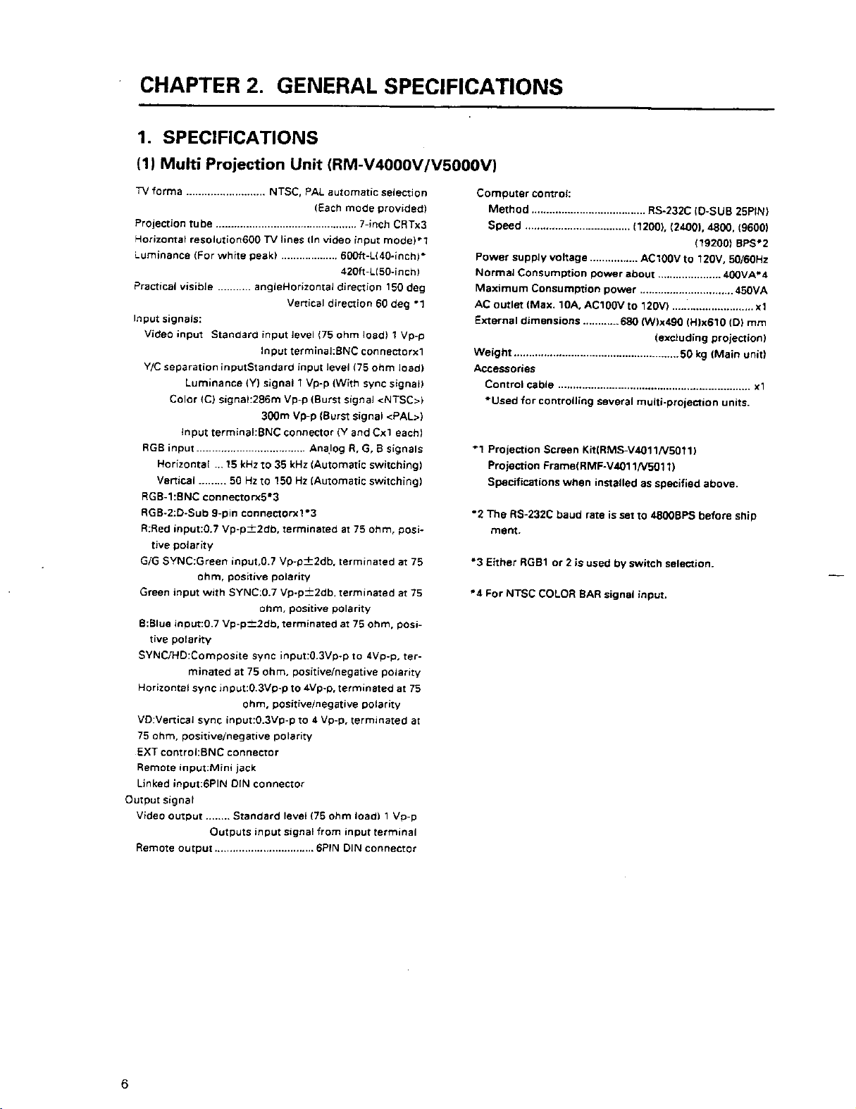
(1) Multi Projection Unit (RM-V4000V/V5000V) ................................................................................................... 6
(2) Projection Screen Kit(RMS-V4011/V5011)Product Weight:11.0kg/14.0kg .................................................. 13
(3) Projection Frame (RMF-V4011/V5011)Product Weight:26.8kg/28.8kg ........................................................ 14
(4) Projection Cabinet(RMF-V4011R) .................................................................................................................. 15
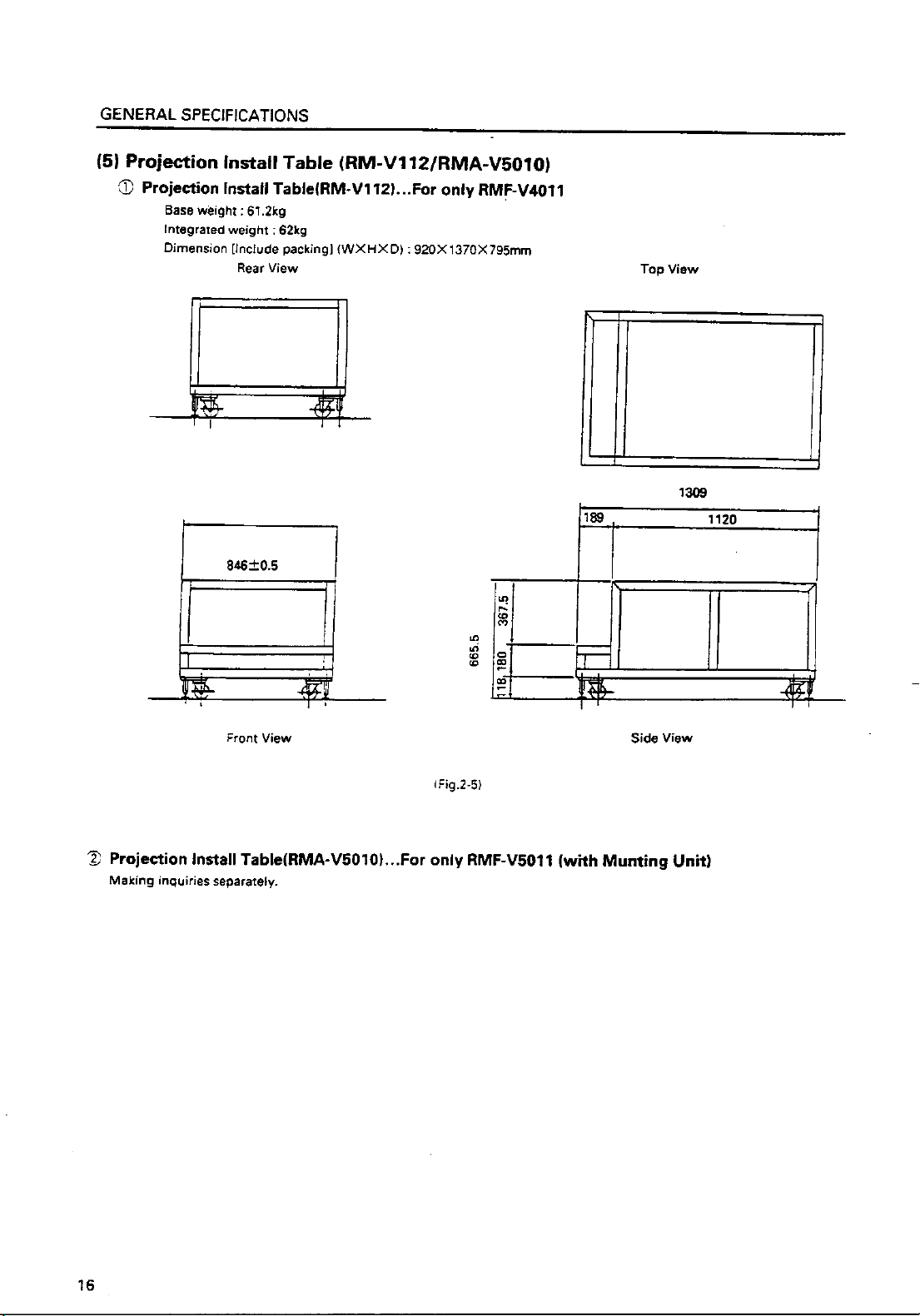
(5) Projection Install Table (RM-V112/RMA-V5010) ........................................................................................... 16
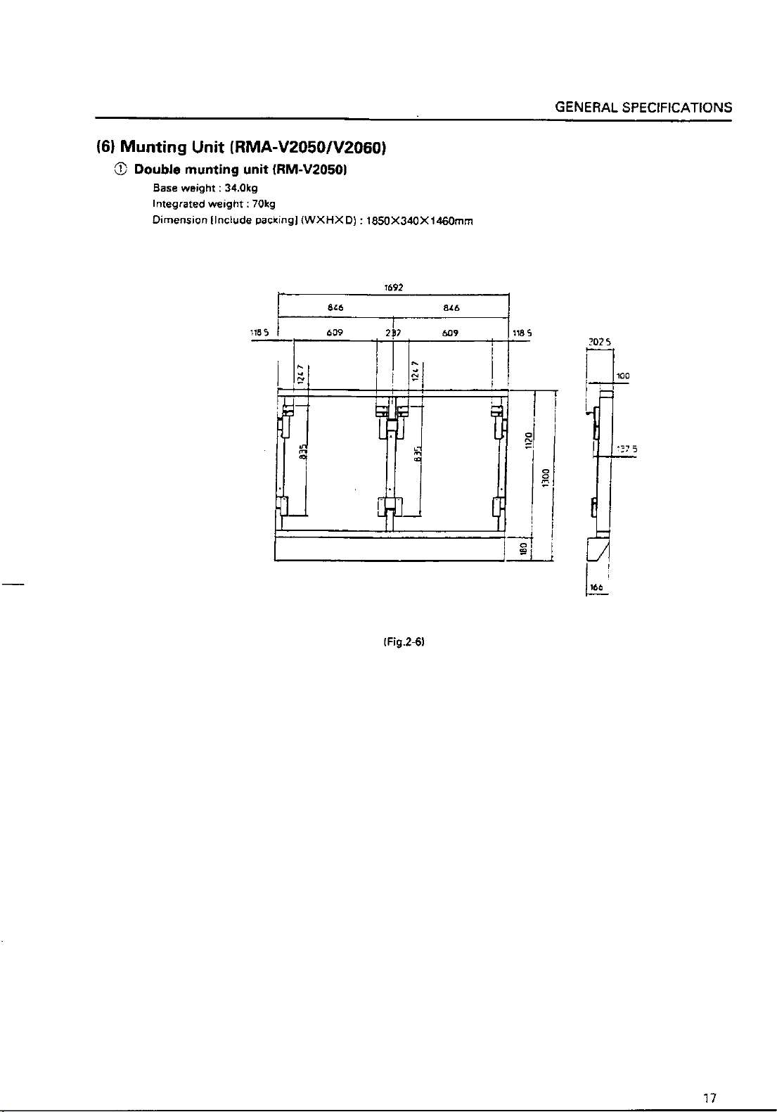
(6) Munting Unit (RMA-V2050/2060) ................................................................................................................... 17
(7) Multi Video Processor(RMD-V3216/3109,RMD-V2170) ................................................................................ 18
(8) Adjustment Control Unit (RU-V107)*Option ................................................................................................ 20
(9) Projection Cabinet (RMF-V4011R) Accessories ............................................................................................ 21
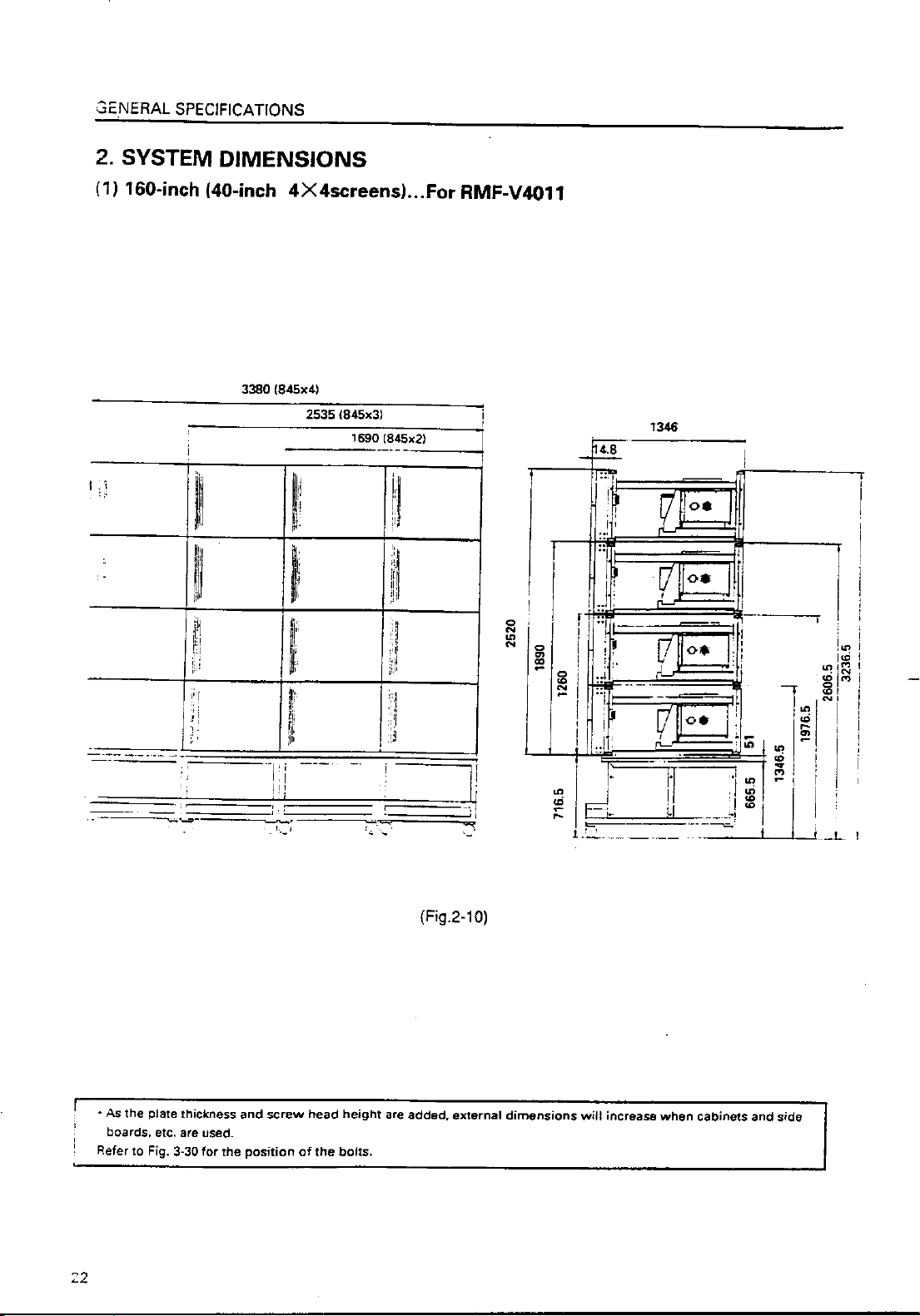
2. SYSTEM DIMENSIONS .......................................................................................................................................... 22
(1) 160-inch (40-inch 4×4screens)…For RMF-V4011 ......................................................................................... 22
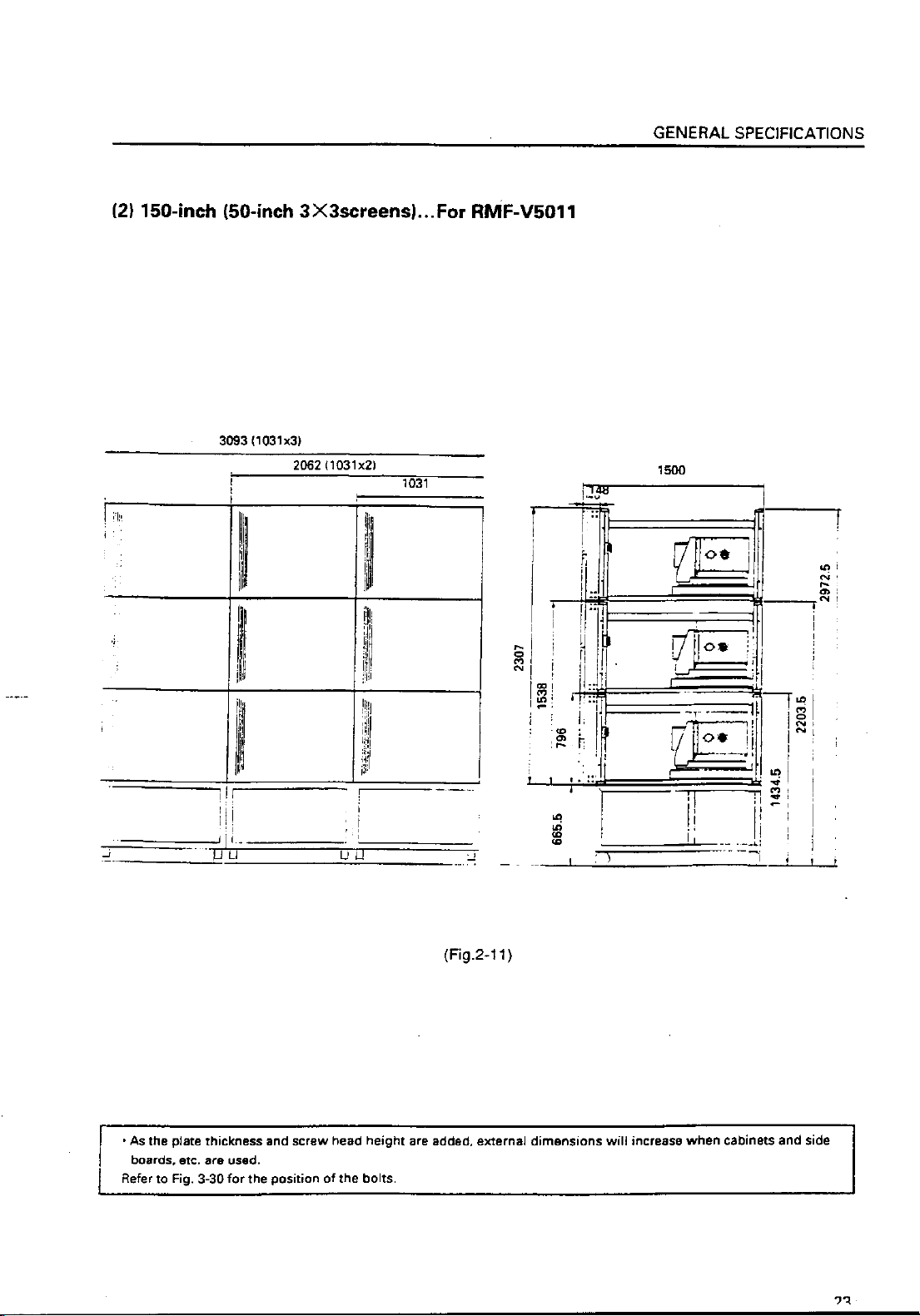
(2) 150-inch (50-inch 3×3screens)…For RMF-V5011 ......................................................................................... 23
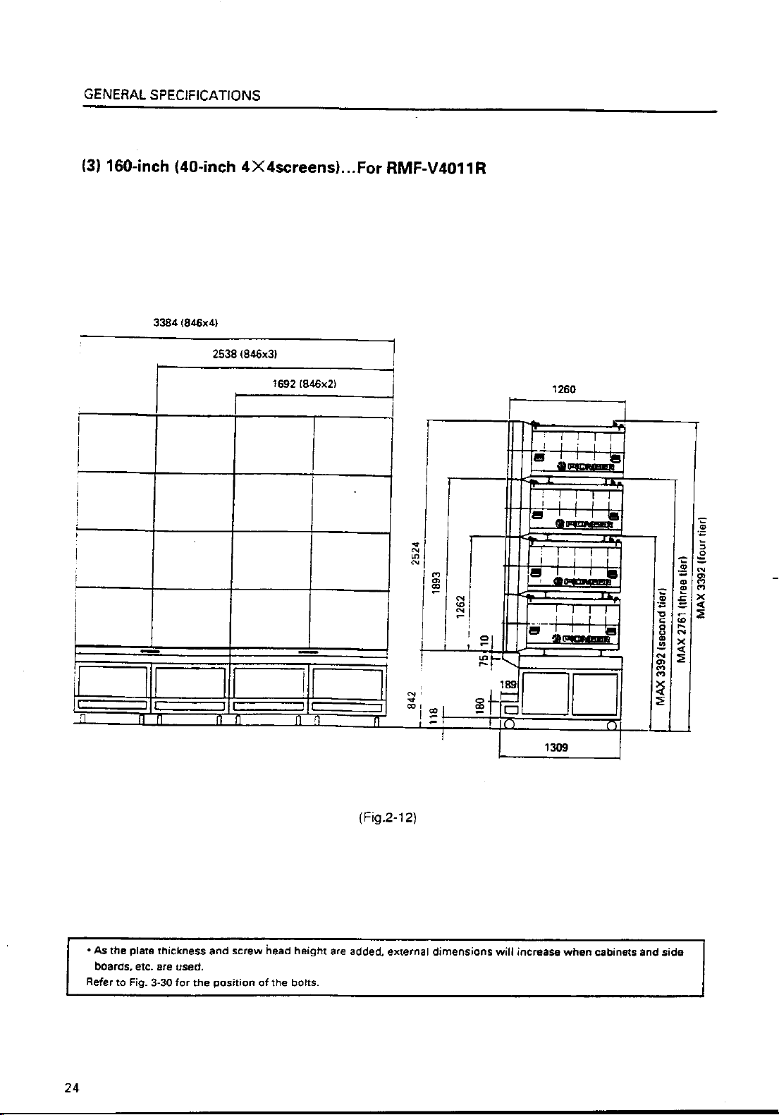
(3) 160-inch (40-inch 4×4 screens)…For RMF-V4011R...................................................................................... 24
CHAPTER 3. INSTALLATION AND ASSEMBLY ............................................................................... 25
1. INSTALLATION CONDITIONS ............................................................................................................................... 25
(1) Installing Ground ............................................................................................................................................ 25
(2) Ceiling .............................................................................................................................................................. 26
(3) Front Space ..................................................................................................................................................... 26
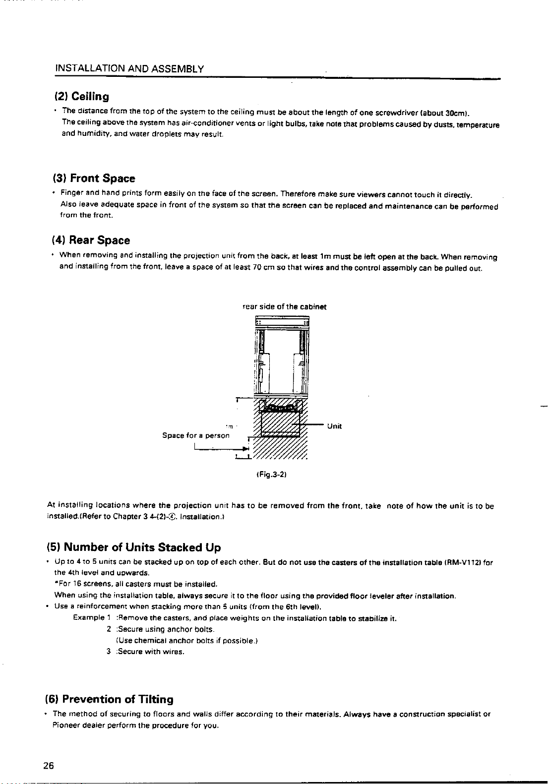
(4) Rear Space ...................................................................................................................................................... 26
(5) Number of Units Stacked Up ......................................................................................................................... 26
(6) Prevention of Tilting ....................................................................................................................................... 26
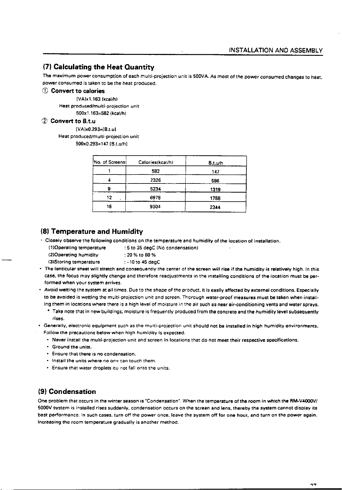
(7) Calculating the Heat Quantity ........................................................................................................................ 27
(8) Temperature and Humidity ............................................................................................................................ 27
(9) Condensation .................................................................................................................................................. 27
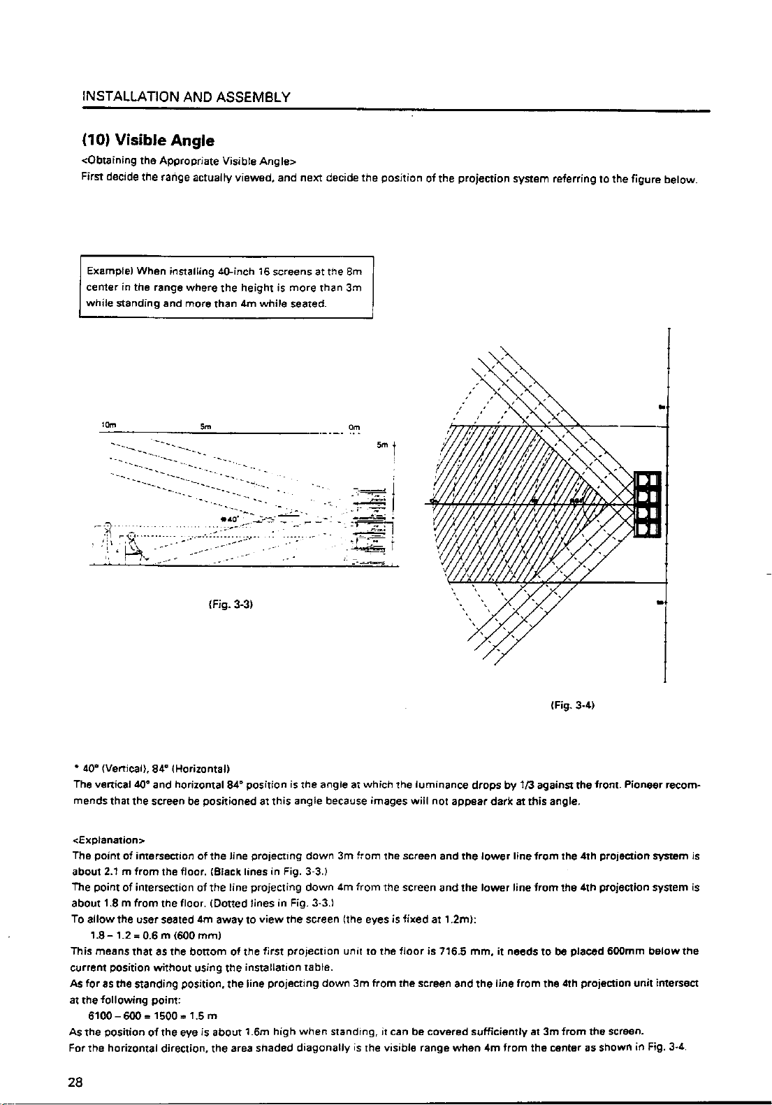
(10) Visible Angle ................................................................................................................................................. 28
(11) Lighting .......................................................................................................................................................... 31
(12) Effects of Earth Magnetism .......................................................................................................................... 31
(13) Connection with a Power Supply ................................................................................................................ 32
(14) Cabes Used ................................................................................................................................................... 33
(15) Semi-outdoor Installation ............................................................................................................................ 33
(16) Precautions for Use of User-Obtained Parts .............................................................................................. 33
2. INSTALLATION AND ASSEMBLY ......................................................................................................................... 34
(1) Confirmation ................................................................................................................................................... 34
(2) Opening the Packaging .................................................................................................................................. 34
(3) Carrying the Units After Opening Packaging ............................................................................................... 39
3. PRECAUTIONS FOR TRANSPORTATION ............................................................................................................. 39
4. ASSEMBLING THE SYSTEM ................................................................................................................................. 41
(1) Assembling the Projection Frame (RMF-V4011/V5011) ............................................................................... 41
(2) Assembling the System ................................................................................................................................. 42
5. SPECIAL INSTALLATION ....................................................................................................................................... 53
(1) Wall inset ......................................................................................................................................................... 53
(2) Diagonal installation ....................................................................................................................................... 53
(3) Architrave processing .................................................................................................................................... 53
(4) Upside down installation ............................................................................................................................... 53
(5) Hanging from ceiling ...................................................................................................................................... 53
CHAPTER 4. ADJUSTMENTS ............................................................................................................ 54
1. ADJUSTMENT PREPARATIONS ........................................................................................................................... 54
(1) Wiring .............................................................................................................................................................. 54
(2) Wiring Handling .............................................................................................................................................. 54
(3) Aging ............................................................................................................................................................... 54
2
Page 4
Page 5
Page 6
Page 7
Page 8
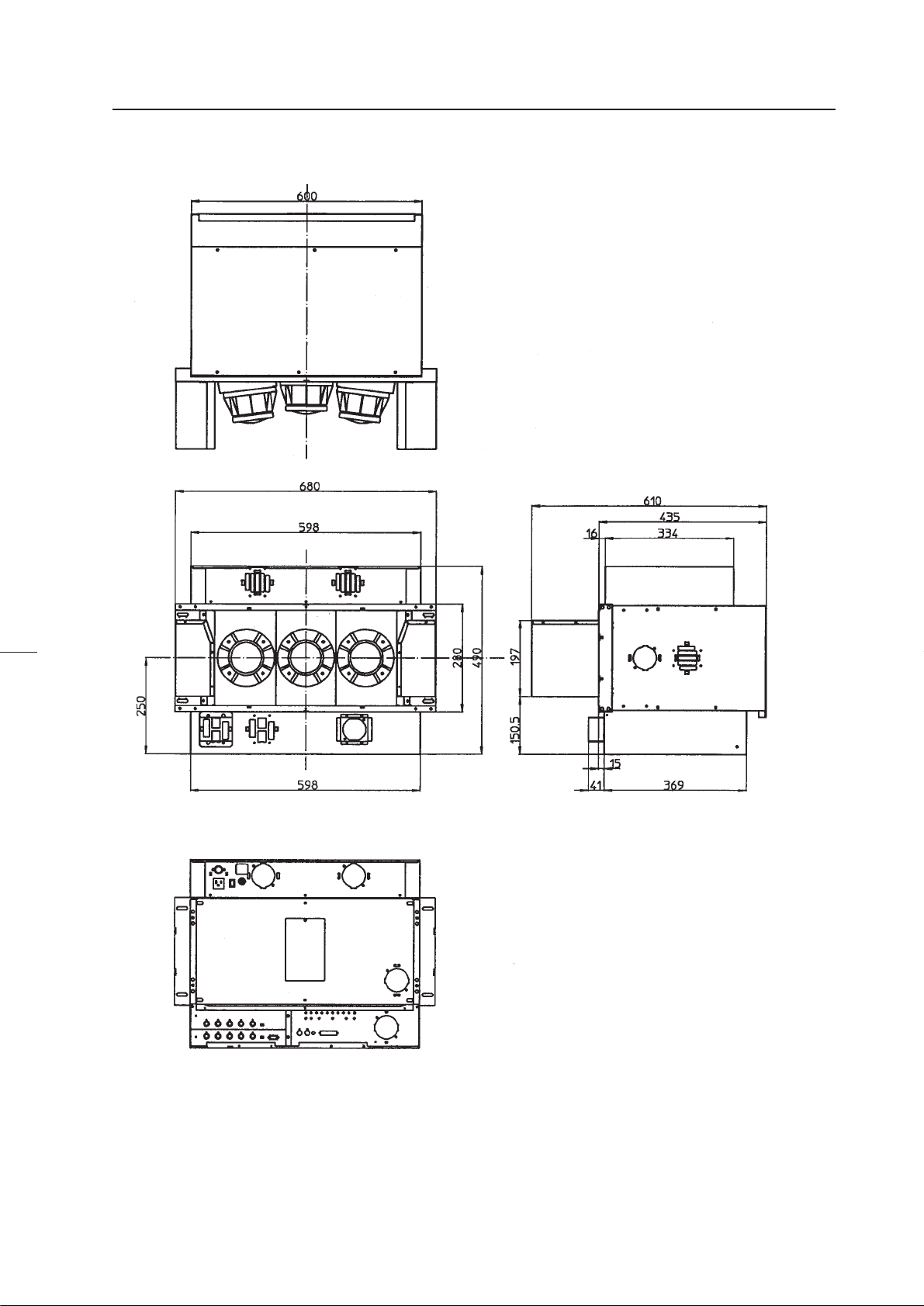
Dimensions
GENERAL SPECIFICATIONS
(Fig.2-1)
7
Page 9
Page 10
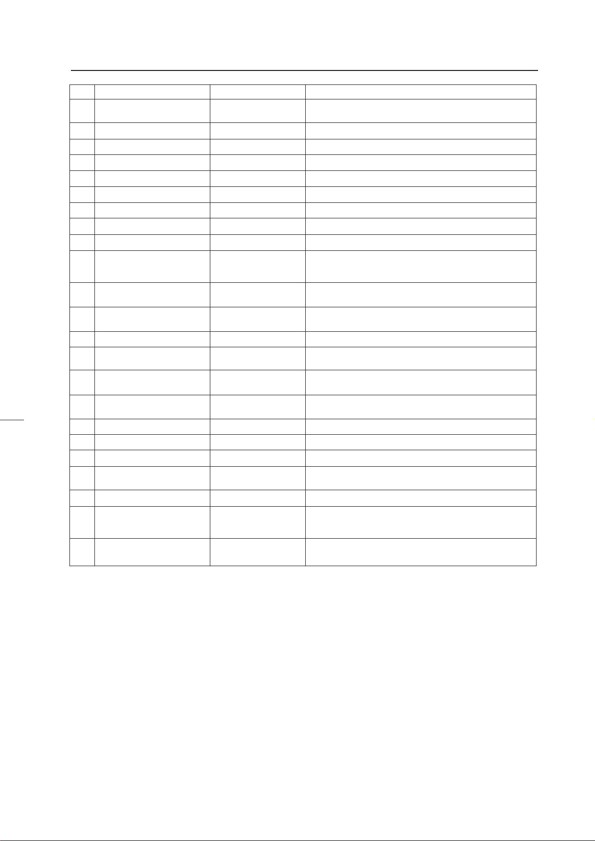
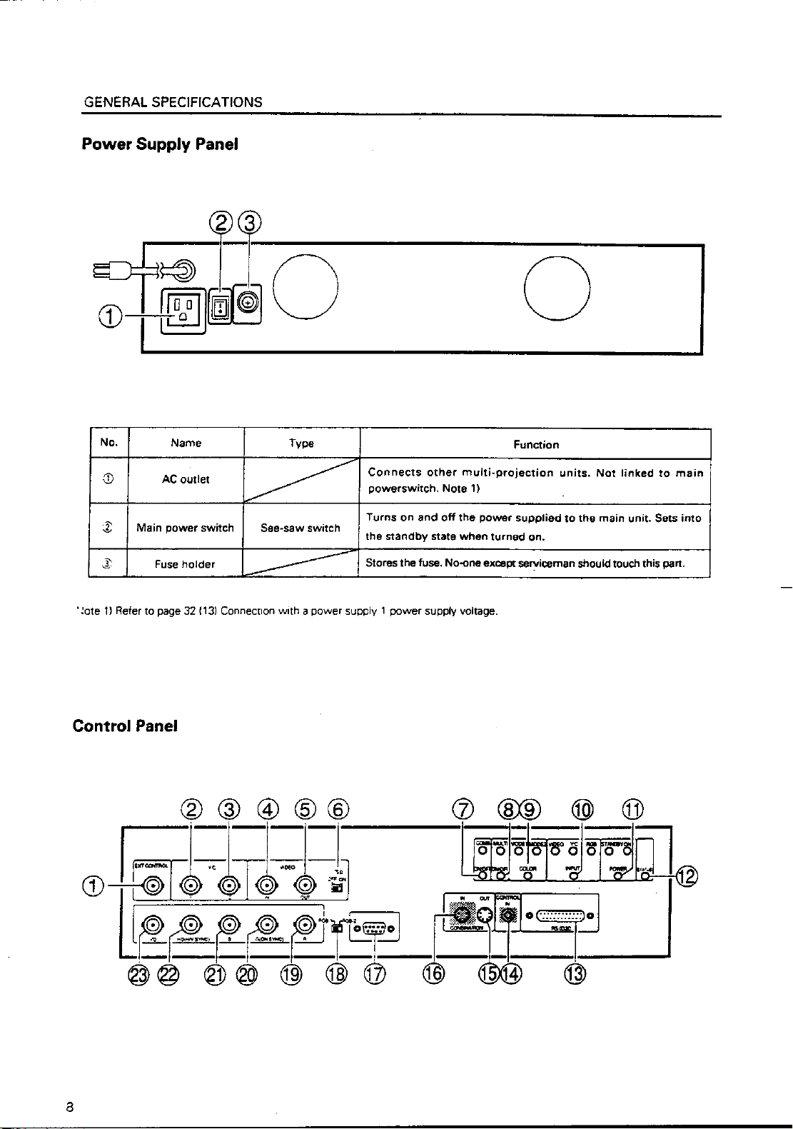
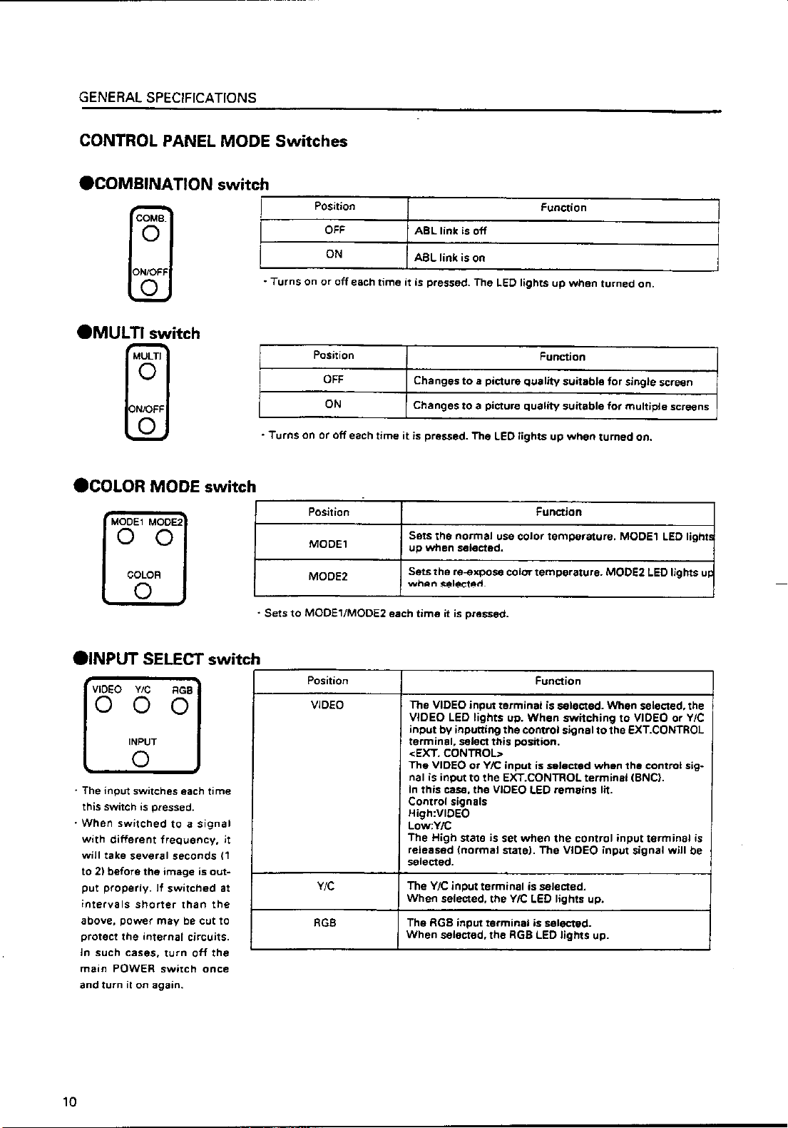
GENERAL SPECIFICATIONS
No.
Control input terminal
1
Y (Luminance) input terminal
2
C (Color) input terminal
3
Video input terminal
4
Video output terminal
5
TERMINATE switch
6
COMBINATION switch
7
MULTI switch
8
COLOR MODE switch
9
INPUT switch
0
POWER switch
-
STATUS switch
=
RS-232C port
~
emote control connection ter
!
minal
Linked output terminal
@
Linked input terminal
#
RGB input terminal
$
RGB input select switch
%
RGB input terminal (R)
^
RGB input terminal
(G/composite sync)
&
RGB input terminal (B)
*
RGB input terminal
(
(Horizontal sync/composite
sync)
RGB input terminal (Vertical
)
sync)
Name
Type
BNC connector
BNC connector
BNC connector
BNC connector
BNC connector
Slide switch
Tact switch
Tact switch
Tact switch
Tact switch
Tact switch
Tact switch
D-sub 25 PIN (Female)
Mini jack
DIN 6PIN
DIN 6PIN
D-sub 9PIN (Male)
Slide switch
BNC connector
BNC connector
BNC connector
BNC connector
BNC connector
Function
Video input and Y/C input external switching control signal input terminal
Luminance signal input terminal
Color signal input terminal
Video signal input terminal
Video input terminal 4 through-out terminal
Terminates the video input terminal 4 at 75 ohm
Turns on when linked to ABL
Turns on when used on multi screen
Switches the color temperature. 1:Normal use. 2:Re-exposure
Switches VIDEO input, Y/C input, RGB input.
Switches VIDEO input and Y/C input with the external control
signal 1 at VIDEO position
Power OFF:STANDBY (Red LED) lights up
Power ON:ON (Green LED) lights up
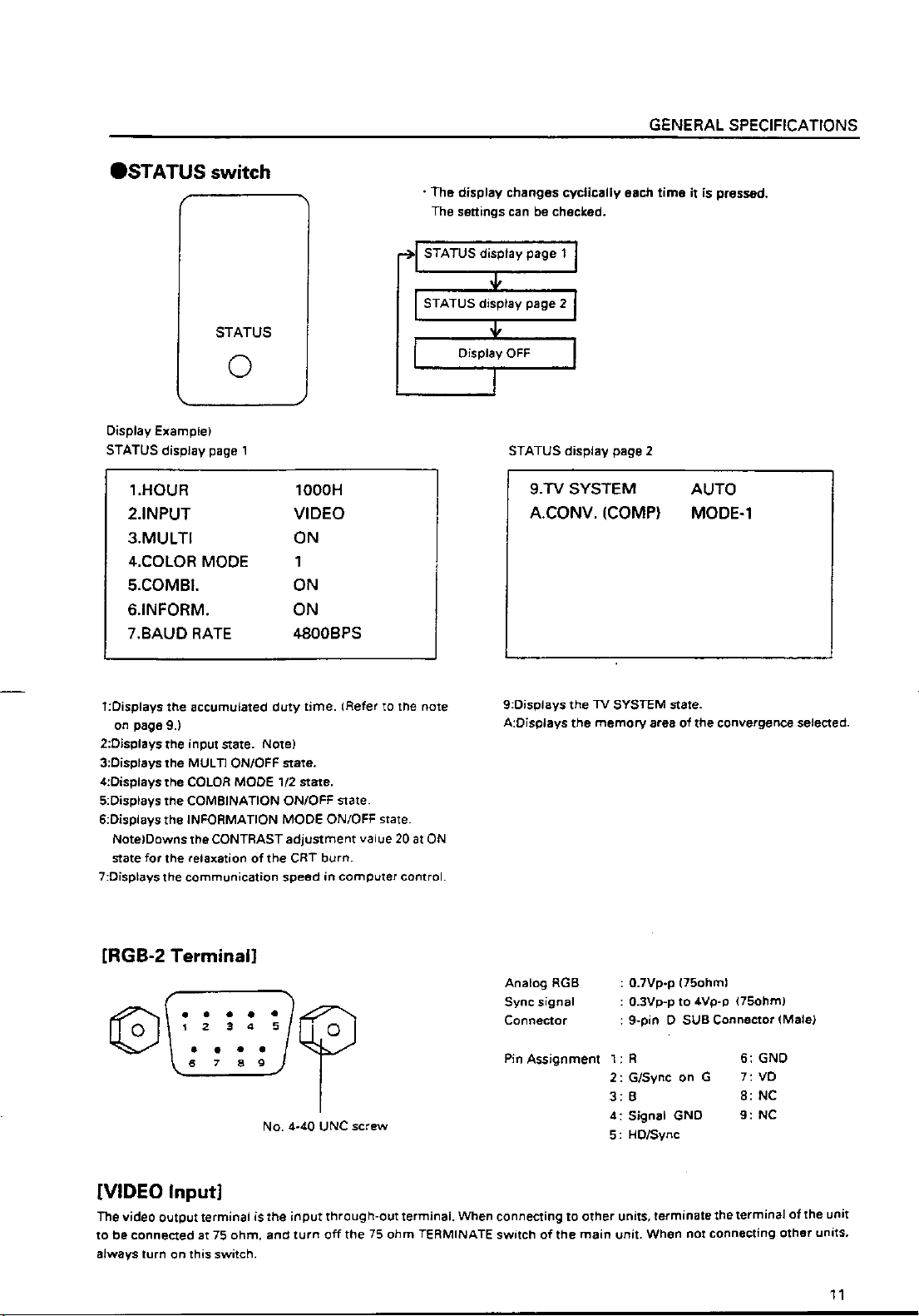
Accumulated duty time:Switch which displays setting states of
each switch on the screen.
RS-232C communication connector
Connected to adjusting remote control (optional)
Output terminal of ABL signal, remote control signal, and RS232C signal
Input terminal of ABL signal, remote control signal and RS232C signal
RGB signal input terminal
Switches RGB signal input terminal type
RGB signal R input terminal
RGB signal G and composite sync (Input signal G on sync) input
terminal
RGB signal B input terminal
RGB signal horizontal sync and composite sync (Only for input
signal H/V sync) input terminal
RGB signal vertical sync input terminal
• To turn off the power, use the POWER switch - of the unit, the RS-232C control, or wired remote control (optional). (If turned
off using the main POWER switch or by disconnecting the power cable from the outlet, the settings of the above 7 to -
switches and the state of the TV SYSTEM and convergence memory will not be recorded on the memory.)
Consequently when starting up or stopping the whole system by AC ON/OFF in setup conditions for a demonstration, it is
necessary to turn off the power using the above method to record each setting in the memory.
*: Counts only when the power is ON and signal has been input to the input function selected. If the main POWER switch is
turned off or the power cable is pulled out of the outlet while the power is on before one hour has passed, errors will occur
in the count.
9
Page 11
Page 12
Page 13
Page 14
GENERAL SPECIFICATIONS
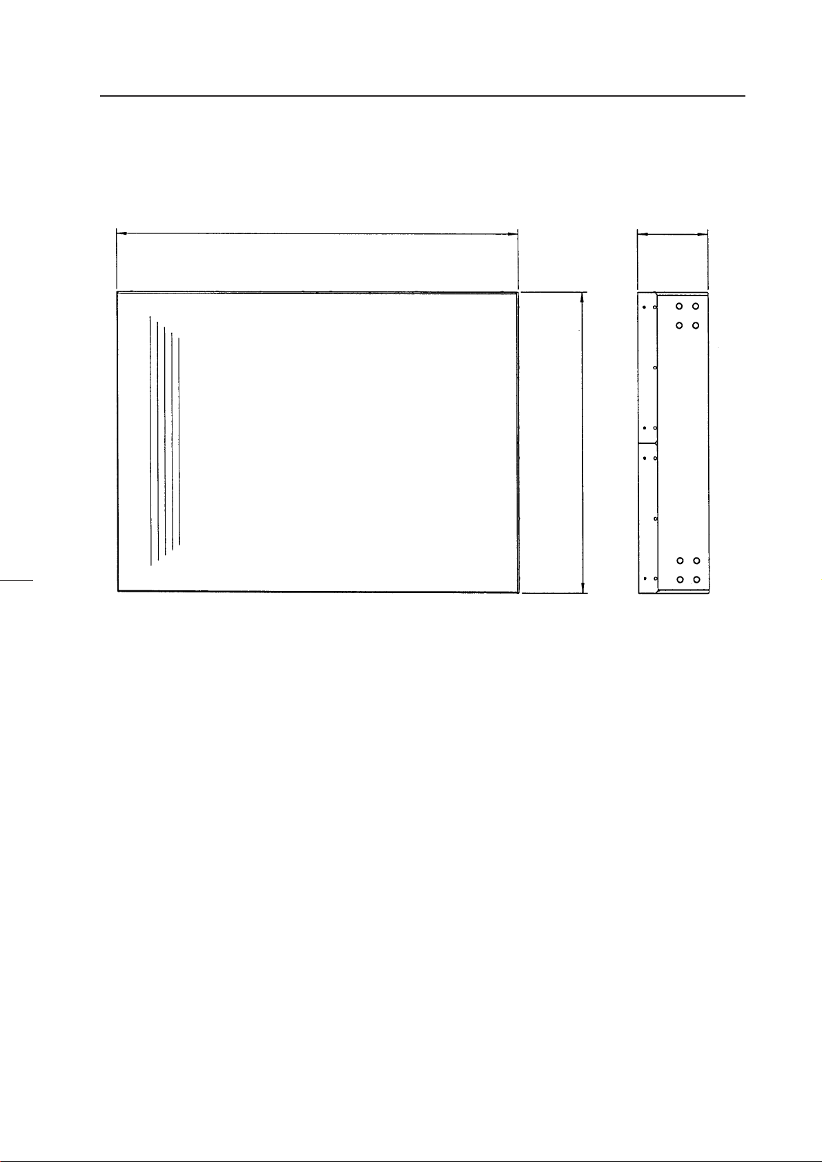
(2) Projection Screen Kit (RMS-V4011/V5011) Product Weight : 11.0 kg/14.0kg
845
148
(148)(1031)
630
(769)
(Fig.2-2)
Accessory
Screw rivet ........................................................................................................................... 6
Unit:mm
The number in parentheses is
the dimentsion for RMS-V5011
13
Page 15
GENERAL SPECIFICATIONS
(3) Projection Frame (RMF-V4011/V5011) Product Weight : 26.8kg/28.8kg
1201(1352)
845(1031)
630
(769)
(Fig.2-3)
Accessories
Metal fixture (R) ................................................................................................................... 1
Metal fixture (L) .................................................................................................................... 1
Stopper ................................................................................................................................. 2
Screw M5x10 .................................................................................................................. 38+2
Screw M5x35 ........................................................................................................................ 6
Screw M5x50 ........................................................................................................................ 4
Hexagon head bolt (with washer) M8x45 .......................................................................... 8
Shield .................................................................................................................................... 1
Rivet ...................................................................................................................................... 2
Unit:mm
The number in parentheses is
the dimension for RMS-V5011
14
Page 16
Page 17
Page 18
Page 19
GENERAL SPECIFICATIONS
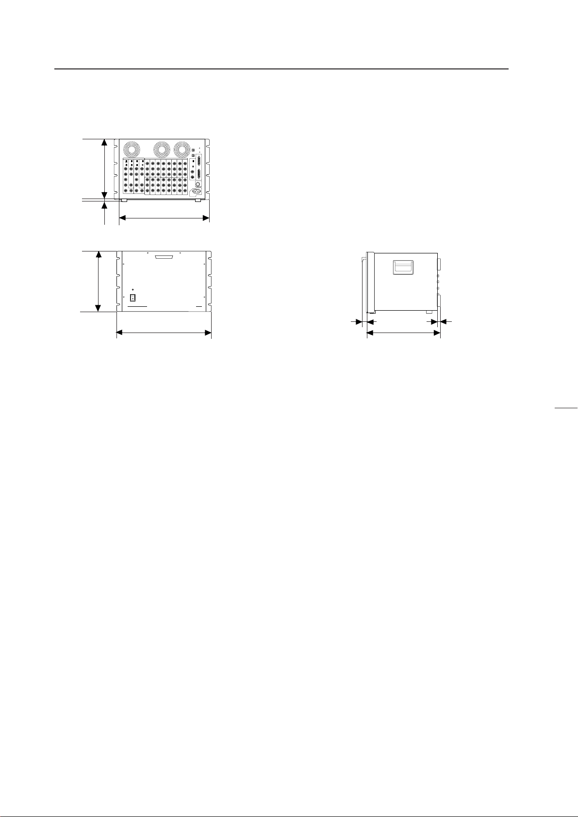
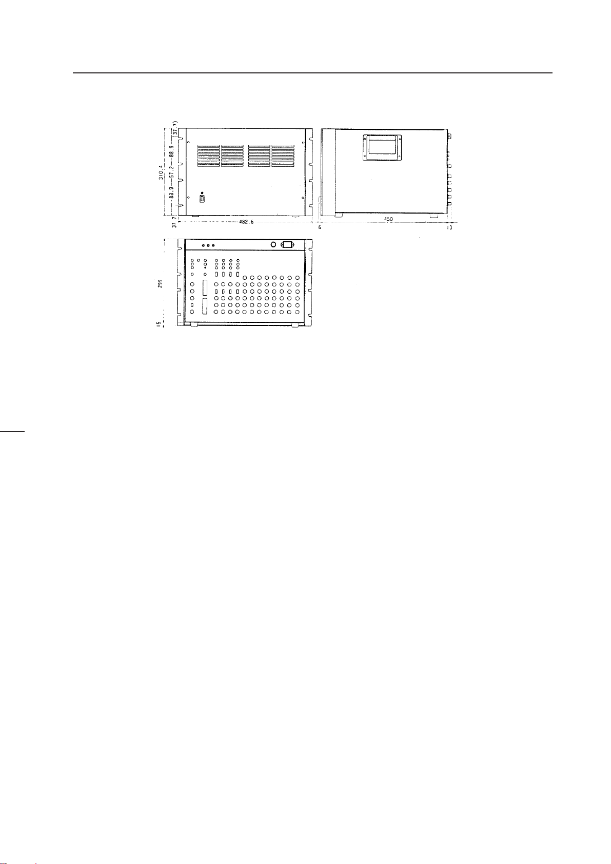
(7) Multi Video Processor (RMD-V3216/V3109, RMD-V2170)
1 Multi Video Processor (RMD-V3216/V3109)
Rear View
0
0
299
15
430
D
314
POWER
ON
OFF
MULTI VIDEO PROCESSOR RMD-V3216
482.6
Front View
Main Specifications of Multi Video Processor
(RMD-V3216/V3109)
Input signal
Input video signal (Can be expanded up to four systems)
2-line (RMD-V3216), 1-line (RMD-V3109) ... BNC terminal
1 Composite video signal ...........................................
....................................... 1.0 Vp-p (75ohm terminated)
2 Y/C separation signal
Y (With sync) ................................1.0Vp-p (75ohm)
C burst level ............................0.286 Vp-p (75ohm)
*1 or 2 signal format can be selected
*Only 1 has a terminate switch, throughout
Input standard sync signal .......................... BNC terminal
1 Composite sync signal ................ 0.286 to 4.0 Vp-p
2 Composite video signal
Video level ....................... 0 to 0.714 Vp-p (75ohm)
Single level ..............................0.286 Vp-p (75ohm)
*Terminate switch, throughout
RS-232C control input 25-pin D-SUB
Output signal
Output video signal
16-line (RMD-V3216), 9-line (RMD-V3109) .. BNC terminal
1 Composite sync signal ................. 1.0 Vp-p (75ohm)
2 Y/C separation signal
Y (With sync) ................................. 1.0Vp-p (75ohm)
C (With burst) Burst level ........ 0.286 Vp-p (75ohm)
*1 and 2 signal formats are output simultaneously.
(Fig.2-7)
16
19
420
Side View
3 RGB signal
Green (Sync on Green) ............................... 1.0 Vp-p
SYNC ............................................................ 0.3 Vp-p
B.R ................................................................ 0.7 Vp-p
Output reference composite sync signal BNC terminal
TTL level
(Or input reference sync signal throughout)
Others
Power supply .............................. AC100 to 120V (50/60 Hz)
Power consumption .............................................................
........................... (RMD-V3216, RMD-V3109) 350W, 700VA
Operating temperature and humidity range ......................
.......................................................................... 5 °C to 35 °C
Below 85% (No condensation)
External dimensions (RMD-V3216, RMD-V3109) ...............
.................. 482.6 (Width)x420 (Depth)x314 (Height) (mm)
(Excluding handle)
Weight
RMD-V3216 ............................................................... 22.5 kg
RMD-V3109 ............................................................... 22.0 kg
Accessories
Rack mounting screw M5 .................................................. 8
Rack mounting washer ...................................................... 8
18
Page 20
2 Multi Video Processor (RMD-V2170)
GENERAL SPECIFICATIONS
Front View
Rear View
(Fig.2-8)
Main Specifications of Multi Video Processor (RMD-V2170)
Input video signal ..........................................NTSC format
Input signal band ...................................... Above 4.2 MHz
Output
Video output
Input
Video input
Input signal ...............................................................
...................... NTSC composite video signal (BNC)
Input system ................................................... 4-line
Standard input level ................... 1Vp-p (75Ω load)
Y/C separation
Input signal ..... NTSC Y/C separation signal (BNC)
Input system ................................................... 4-line
Standard input level ............... Y:1 Vp-p (75Ω load)
..................... C:286 mVp-p (75Ω load burst signal)
*The video input or Y/C separation input is to be
selected by the switch on the rear panel.
Reference sync signal input
Input signal ..............................Composite sync (BNC)
Standard input level .....................................................
...................................... Composite sync 0.3 to 4 Vp-p
Control input
Input signal ..... Conforms to RS-232C (25-pin, D-sub)
Y/C separation output
Test signal output
Output signal ..................................................................
............................ NTSC composite video signal (BNC)
Standard output level ....................... 1Vp-p (75Ω load)
Sync signal output ...............................TTL level (BNC)
Power supply voltage ...................... 100 to 120V, 50/60 Hz
Power consumption ....................................... 300W/500VA
External dimensions ........... 483 (W)x314 (H)x469 (D) mm
Weight .......................................................................... 33 kg
Side View
Output signal.............................................................
....................... NTSC composite video signal (BNC)
Output system................................................16-line
Standard output level .................. 1Vp-p (75Ω load)
Output signal... NTSC Y/C separation signal (BNC)
Output system................................................16-line
Standard output level ............... Y1 Vp-p (75Ω load)
....................... C286 mVp-p (75Ω load, burst signal)
*Line up series of RMD-V2110 with 9 OUTPUT CIRCUITS.
19
Page 21
GENERAL SPECIFICATIONS
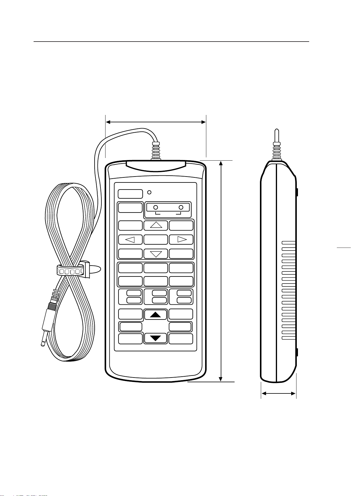
(7) Adjustment Control Unit (RU-V107)*Option
84
POWER
0
13
46
79
D
ADJUSTMENT CONTROL UNIT
RU-V107
ADJ IN
2
5
8
Î
ABC
DEF
ADJ ADJ ADJ
RGB
ON/OFF ON/OFF ON/OFF
INPUT SEL
2//3
–+
DISP CALL
MAIN MENU
ADJ OUT
187
(Fig.2-9)
Accessories
AA dry battery (IEC R6P) ..................................................................................................... 2
Cable (5m) ............................................................................................................................ 3
20
29
Page 22

GENERAL SPECIFICATIONS
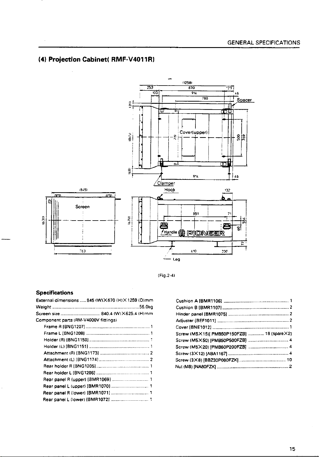
(8) Projection Cabinet (RMF-V4011R) Accessories
To attach the multi-projection unit (RM-V4000V) to the conventional RM-V2000A, the RMF-V4011R accessories (metal fixtures)
are required. The following lists the required parts. For details of attaching the multi-projection unit, refer to Chapter 3. "4-
(2)Assembling the System".
Frame R (BNG1207) ...................................................................................................... 1
Frame L (BNG1208) ....................................................................................................... 1
Holder (R) (BNG1150) ................................................................................................... 1
Holder (L) (BNG1151) .................................................................................................... 1
Attachment (R) (BNG1173) ........................................................................................... 2
Attachment (L) (BNG1174) ........................................................................................... 2
Rear holder R (BNG1205) ............................................................................................. 1
Rear holder L (BNG1206) .............................................................................................. 1
Rear panel R (upper) (BMR1069) ................................................................................. 1
Rear panel L (upper) (BMR1070) .................................................................................. 1
Rear panel R (lower) (BMR1071) .................................................................................. 1
Rear panel L (lower) (BMR1072) .................................................................................. 1
Cushion A (BMR1106) ................................................................................................... 1
Cushion B (BMR1107) ................................................................................................... 2
Hinder panel (BMR1075) ............................................................................................... 2
Adjuster (BEF1011) ........................................................................................................ 2
Cover (BNE1012) ........................................................................................................... 1
Screw (M5x15) (PMB50P150FZB) .............................................................. 18 (Spare 2)
Screw (M5x50) (PMB50P500FZB) ................................................................................ 4
Screw (M6x20) (PMB60P200FZB) ................................................................................ 4
Screw (3x12) (ABA1167) ............................................................................................... 4
Screw (3x8) (BBZ30P080FZK) ..................................................................................... 10
Nut (M8) (NA80FZK) ...................................................................................................... 2
21
Page 23
Page 24
Page 25
Page 26
CHAPTER 3. INSTALLATION AND ASSEMBLY
1. INSTALLATION CONDITIONS
(1) Installing Ground
1 Ground
The ground must be flat and horizontal. It should be able to bear the weight of the system.
For wooden floors, if the part receiving the weight of the system lies at the center between the reinforcement beams below the
floor, the floor may become deformed or may curve inwards. In such cases, lay a more than 12 mm thick board below the
system to distribute the weight of the system on the floor.
For concrete floors, it may not be possible to install the system horizontally due to the roughness of the floor. In such cases, do
the same as above.
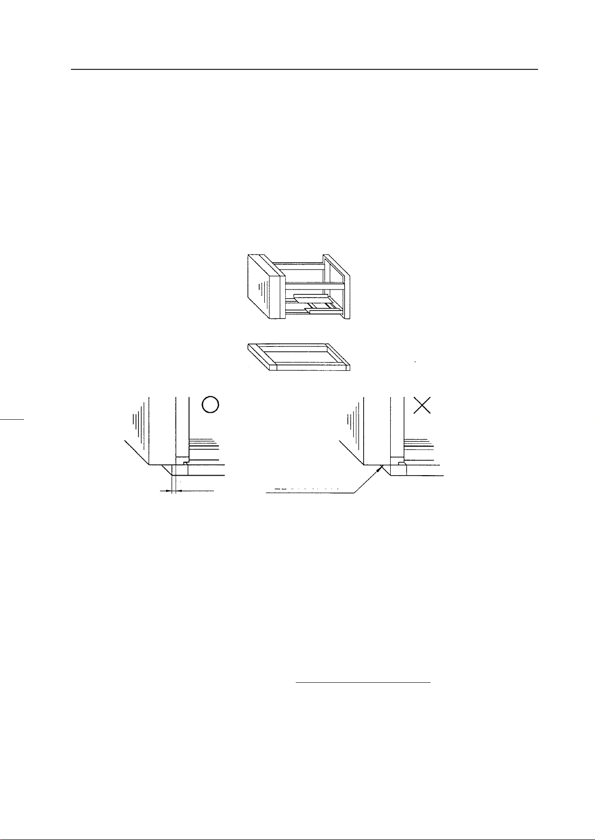
When installing the system on a installation table, always place the screen unit and cabinet on the same level of the installa-
tion table. The screen should also be more than 15 mm inside the edges of the installation table.
The bottom of the screen is
More than 15 mm
not on the installation table.
(Fig.3-1)
2 How to culculate weight
Example : 40-inch Cube × 16screens
RM-V4000V (Multi-Projection Unit) 50kg × 16 = 800kg
RMS-V4011 (Projection Screen Kit) 11kg × 16 = 176kg
RMF-V4011 (Projection Frame) 27kg × 16 = 432kg
RMS-V112 (Projectin Install Table) 54kg × 4 = 216kg
Total : 1744 kg + α (screw, others)
Note) Other than the above weights, the weight of the person installing the system are also added.
For 16 screens, about 3 to 4 persons=240 kg (15% of total weight).
25
Page 27
Page 28
Page 29
Page 30
Page 31
Page 32

INSTALLATION AND ASSEMBLY
(11) Lighting
• The projection screen kit (RMS-V4011/V5011) will not reflect like TV screens when exposed to external light, but may reflect
if directly exposed to strong lights such as spotlight. Therefore, make sure that the screens are not exposed to direct
spotlight.
• For certain installation location conditions, a glass sheet may have to be attached to the screen surface. In this case, as there
will be reflection by external light, consider the installation position, etc. carefully.
• As the actual intended images of the system may not be obtained in very bright locations, consider the position of lighting
and direction of sunlight when installing the system.
(12) Effects of Earth Magnetism
• Due to effects of earth magnetism, the position of the image displayed will differ according to the installed direction.
Difference is about several mm in the up/down/left/right directions, but the degree of change varies according to the
strength of the earth magnetism of each area.
• Misconvergence may also occur due to slight rotations.
• Therefore, when performing adjustments before bringing the system into the installing location. Perform the adjustments
in the same direction and angle as installation, perform adjustments again at the final location decided.
• If the system is used at a fixed position, adjust it at the final position used.
• The system is not only affected by earth magnetism but by the following magnetisms generated by various items in its
surrounding as well.
• Steel frame of building
• Power cables on the floor
• Large speaker systems
• Special equipment (Those generating magnetic force)
• Metallic installation table, frames, etc.
31
Page 33

Page 34

Page 35

INSTALLATION AND ASSEMBLY
2. INSTALLATION AND ASSEMBLY
(1) Confirmation
1 Decide the position for installing the system according to the installation conditions in Chapter 3.
Check Items
[1] Dimensions of installing position, space at the back, distance to the ceiling
[2] Floor flatness, strength, roughness
[3] Position of power supply
[4] Installing location
Necessity ti strengthen the floor, wall, etc.(reinforcement cover, sheet, plank, etc.), path used to transport the system,
width of passage, if elevator is available , its size and maximum bearing weight, etc.
[5] Position, specifications, and structure of a transmission equipment, and image type
[6] Model number of equipment used, and their quantity (perform according to list).
Check if there is enough equipment for each unit
*These procedures must be performed by only one person.
(2) Opening the Packaging
1 Packaging specifications
[1] Multi Projection Unit (RM-V4000V/V5000V) : 769(W) × 690(H) × 738(D) 61.0kg
[2] Projection Screen Kit (RMS-V4011) : 940(W) × 230(H) × 730(D) 15.7kg
(RMS-V5011) : 1126(W) × 230(H) × 879(D) 20.2kg
[3] Projection Frame (RMF-V4011) : 950(W) × 180(H) × 1300(D) 31.2kg
(RMF-V5011) : 1160(W) × 250(H) × 1475(D) 35.4kg
[4] Projection Cabinet (RMF-V4011R) : 1006(W) × 859(H) × 1454(D) 68.0kg
2 Opening the packaging
Open from the big ones first and put the small packagings inside the empty big packagings. Also dispose or store the
packagings.
Do not mix up the opened items with those still in the packaging.
Move the empty packagings somewhere else so that they will not come in the way. Next, obtain an assembly space that is as
wide as possible.
* Turn down the opened packagings upside down to differentiate them from those not opened.
Do not lose accessories, the warranty card, etc.
34
Page 36

3 Multi Projection Unit (RM-V4000V/V5000V)
[1] Open the upper carton, and remove the ABL cable and instruction manual provided.
[2] Remove the upper carton (the pad will be connected to the upper carton).
[3] Remove the upper pad.
[4] Take out the unit (must be taken out by two persons).
INSTALLATION AND ASSEMBLY
[1]
[3]
[2]
[4]
(Fig.3-7)
35
Page 37

INSTALLATION AND ASSEMBLY
4 Projection Screen Kit (RMS-V4011/V5011)
* Projection screen kit is double-packaged to maintain its performance. After removing the middle cover protecting its screen,
make sure the screen does not get scratched or dirty.
[1] Remove the top cover.
[2] Remove the band securing the middle cover and remove the middle cover.
[3] Gently peel off the black tape pasted at the four sides of the screen.
Be careful not to damage the lenticular sheet.
[4] Take out the screen unit from the box and stand it on a flat floor, paying attention to its top and bottom.
[5] Remove the eight screws for transportation (gold), four protection panels, white sheet at the back of the screen, and the
bag containing accessories attached to the top of the frame.
* The protection panel is attached with the transportation screws. Keep the removed panel if required. When storing
the system, do not remove the outermost protection panel.
[6] When opening the packagings of several units first, after opening them, place them in a different place to protect them
from damage, and place a sheet over them to protect them from dusts.
[1]
[3]
Transportation screws (Eight:Gold)
Protection panel
Top cover
Black tape
[2]
[4]
Flat floor
Bag containing
accessories
Instruction manual
Middle cover
Band
Bag containing
accessories
Top
Right side
36
[5]
White sheet
(Fig.3-8)
Page 38

INSTALLATION AND ASSEMBLY
5 Projection Frame (RMF-V4011/V5011)
[1] Open the upper carton and cut the PP bands (eight) securing the internal parts.
[2] Remove the two horizontal frame assemblies (packaged in a card box), fixtures (R) and (L).
[3] Remove the H-shape frame assembly (L).
[4] Remove the base assembly.
[5] Remove the H-shape frame assembly (R).
[6] Remove the shield attached to the under carton, bag containing accessories, and instruction manual.
Bag containing accessory
Fixture (R)
H-shape frame assembly (L)
Base assembly
Band A
Horizontal assembly
Fixture (L)
H-shape frame assembly(R)
Shield
(Fig. 3-9)
37
Page 39

INSTALLATION AND ASSEMBLY
6 Projection Cabinet (RMF-V4011R)
[1] Open the upper carton and remove packings B and C, and the instruction manual.
[2] Remove the upper carton.
[3] Remove the top sheet B and peel off the front and back sheets B.
[4] Remove the cabinet. (Hold the handle of the cabinet by two persons.)
[5] Remove sheet B.
[6] Remove the parts from the under carton.
38
(Fig. 3-10)
Page 40

INSTALLATION AND ASSEMBLY
(3) Carrying the Units After Opening Packaging
To carry the screen unit and multi-projection unit after opening the packaging, hold them by the parts shown in the figure, and
lift and move them.
Screen Unit
(Lifted by one or two persons)
Hold the parts indicated by
(Fig. 3-11)
• Never drag the system along the floor when moving the units.
• The lenticular sheet damages very easily as it is very thin. Therefore move it gently and do not apply excessive shock or
vibration to it.
• As the panels supporting the screen are very thin and deform easily, be careful that they do not hit or get hooked onto
surrounding objects when moving them.
Multi-Projection Unit
(Must be lifted by two persons)
3. PRECAUTIONS FOR TRANSPORTATION
Do not stack the units on their sides or backs when transporting them.
Always place them upright. If they are stacked on their sides or backs, vibration and shock may cause damage or fire hazards.
39
Page 41

Page 42

INSTALLATION AND ASSEMBLY
4. ASSEMBLING THE SYSTEM
(1) Assembling the Projection Frame (RMF-V4011/V5011)
Assemble the projection frame as follows.
[1] Mount the stopper onto the base assembly and tighten the screws (M5 × 35). (2 × 2 points)
[2] Mount the H-shape frame assemblies (R) and (L), and tighten the screws (M5 × 10). (4 × 4 points)
[3] Mount the horizontal frame assemblies (two) and tighten the screws (M5 × 10). (4 × 4 points)
* As for the positions for tightening the screws in steps 2 and 3, push the frame against the corner fixtures in the two
directions indicated by the arrow.
[4] Mount the shield onto the H-shape frame assembly (L) using the rivets, peel off the paper on the shield and paste a
magic tape on the H-shape frame assembly (L).
[5] Attach the fixtures (R) and (L) and tighten the screws (M5 × 10). (3 × 2 points)
[6] Place the projection unit on the base assembly, and secure the fixtures (R) and (L) and projection unit to each other with
the screws (M5 × 10). (2 × 2 points)
[7] Secure the movable part of the base assembly with the two screws (M5 × 35).
H-shape frame assembly (L)
5 Shield
2 H-shape frame assembly (L)
1 Screw (M5 × 35)
4 Rivet
3 Horizontal frame assembly
A-5
Holder (L)
1 Stopper
2 H-shape frame
assembly (R)
Table
1 Base assembly
A-7
B-6
Screw (M5 × 35)
A-5 Holder (R)
B-5 Guide fixture
(Fig. 3-13)
41
Page 43

INSTALLATION AND ASSEMBLY
(2) Assembling the System
The basic procedure for assembling the system is as follows.
1 Assemble the projection stand (RM-V112/RMA-V5010).
2 Mount a one-link mount unit . (40-inch only)
3 Assemble the projection frame (RMF-V4011/V5011).
4 Mount the multi-projection unit (RM-V4000V/V5000V).
5 Mount the projection screen kit (RMS-V4011/V5011).
6 Mount the top board , side board , rear panel.
The basic procedure for assembling the system for rental-use is as follows.
1 Assemble the projection stand (RM-V112).
2 Mount the 2-link/3-link mount unit (RMA-V2050/V2060).
3' Mount the multi-projection unit (RM-V4000V) to the projection cabinet (RMF-V4011R).
4' Mount the projection cabinet (RMF-V4011R).
The above procedure is recommended. It is explained below.
1 Projection Install Tables (RM-V112/RMA-V5010)
Place the installation tables (RM-V112) at the specified position and link them together with the bolts and nuts specified.
First tighten the bolts and nuts temporarily, and after all have been linked, check their height differences and if they are
horizontal before tightening the nuts and bolts firmly.
Do not tighten the adjusters at the legs as their final positions have to be adjusted after assembling all units.
To install at a height greater than the installation table when not using this table, make sure the strength is greater than
required.
2 Mount Unit (RMA-V2050/V2060)
Place the mount unit on the stand and join them using the specified bolts and nuts.
As the horizontality, difference in level, etc. of the mount units form the basis of the whole system assembled, assemble them
accurately.
If gaps are formed between the mount unit and the stand due to the difference in height, use the floor leveler of the stand to
adjust the height, or place spacers between the mount unit and stand (metal plates about 1 to 2 mm thick).
When using several mount units, adjust their height, horizontality, etc.
In the case of the system for rental-use, mount the conventional mount units (RMA-V2050/V2060) using the conventional
method. For details, refer to the RM-V2000A technical manual.
42
Page 44

Page 45
INSTALLATION AND ASSEMBLY
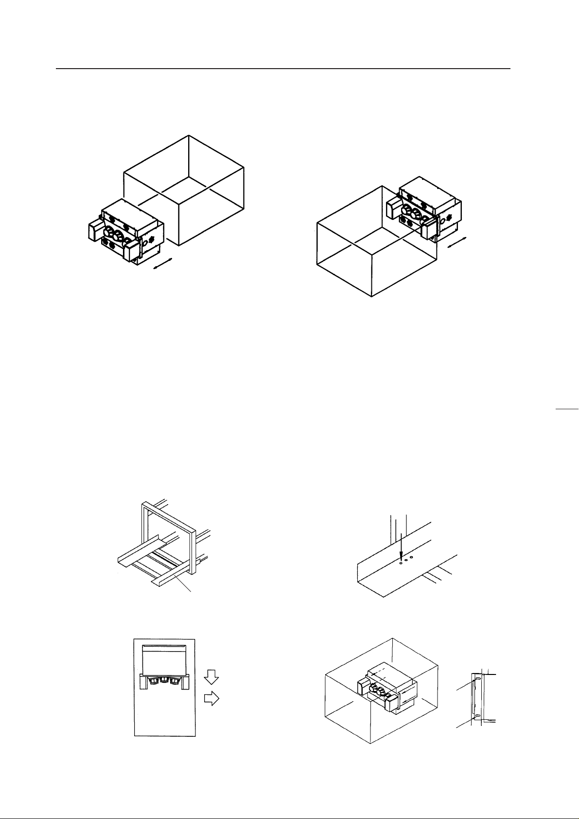
4 Multi Projection Unit (RM-V4000V/V5000V)
The Multi-Projection Unit is designed to be mounted from the back of the cabinet normally. If sufficient space cannot be left at
the back, it can be mounted from the front.
Mount from front
(Fig.3-18)
Mount from back
a When mounting from the back
[1] Pull the table of the cabinet to the back. (Fig. 3-19)
[2] Insert the (M5 × 35) into the holes (Fig. 3-20) on the table. (To prevent the table from moving when placing the projection
unit.)
[3] Place the multi-projection unit on the table and decide the position.
The position should be so that the front of the multi-projection unit will touch the metal fixtures while the sides touch the
guide fixtures (right side as viewed from the screen side). (Fig. 3-21)
[4] Secure the multi-projection unit to the metal fixtures of the cabinet with the four (M5 × 50). (Fig. 3-22)
[5] Remove the inserted into the table at step 2, and push in until the table touches the stopper.
44
Table
(Fig. 3-20)(Fig. 3-19)
(Fig. 3-22)(Fig. 3-21)
Page 46

INSTALLATION AND ASSEMBLY
b When mounting from the front
[1] Remove the two stoppers and two metal fixtures from the cabinet. (Fig. 3-23)
[2] Pull the table to the front.
[3] Insert the screws (M5 × 35) into the holes on the table.
[4] Place the multi-projection unit on the table.
[5] Attach the metal fixtures to the table.
[6] Decide the position of the multi-projection unit and attach it to the metal fixture with the four (M5 × 10). (Fig. 3-24)
[7] Remove the screws inserted into the table at step [3], and push in until the stopper can be attached.
*As there are no stoppers at the back, be careful not to push the table in excessively.
[8] Re-tighten the stopper at the initial position.
[9] Pull out the table until it touches the stopper.
[10] Secure the cabinet table to the cabinet with the two (M5 × 35).
(Fig.3-23) (Fig.3-24)
45
Page 47

INSTALLATION AND ASSEMBLY
5 Projection Screen Kit (RMS-V4011/V5011)
[1] Mount the screen unit serving as the reference. Basically, mount from the center unit at the bottom.
a If the number of units arranged are odd (E.g.: 3 × 3=9 screens)
• Adjust the screen unit to the cabinet at the center of the bottom level and temporarily tighten the linking bolts. (Do not
tighten tightly.)
• Adjust the left and right balance with your hand and tighten the linking bolts tightly so that the two centers coincide.
Top view
Projection Frame
Reference Unit
Linking bolt
Adjust the left and
right balance with
your hand.
(Fig. 3-25)
Projection screen
Linking bolt
Adjust the left and
right balance with
your hand.
b If the number of units arranged are even (E.g.: 4 × 4=16 screens)
• Adjust the screen unit to the right cabinet (or left cabinet) at the center two cabinets of the bottom level and temporarily
tighten the linking bolts. (Do not tighten tightly.)
• Adjust the left side of the screen unit attached and left side of the cabinet (rights sides if the screen unit was attached to the
left cabinet at the center) so that they are aligned precisely with your hand, and tighten the linking bolts.
• Join the left side (or right side) screen unit to the unit mounted first as closely as possible.
46
Adjust so that they are aligned precisely
Reference Unit
(Fig.3-26)
Page 48

INSTALLATION AND ASSEMBLY
[2] Join the next screen beside the screen mounted as the reference and mount the remaining screens in order. (Stack them
from the bottom to the top.)
[3] If necessary, attach the screw rivet (BEC1082) provided as the accessory of RMS-V4011. (Fig. 3-27)
(Fig. 3-27)
* This part is used to shield the light leaking from the big hole (ø 8) on the outermost side of the left and bottom projection
units (diagonally shaded part in Fig. 3-28) after installing the system. Use it if necessary.
Screen units with this rivet cannot be attached outside the area indicated by the standing lines in fig. 3-28.
(It will not connect to the adjoining units.)
(Fig. 3-28)
<Note>
• Do not mistake the top and bottom of the screen unit. The side with the longer screw projecting out (side with transportation
screw) is the top and the side with the 8 mm hole is the bottom.
• Before mounting the screen unit to the cabinet, check that the transportation screw, protection panel, and black tape have
been removed. (Do not remove the protection panel on the outer-most side when installing the system.)
• Always tighten the linking bolts of the cabinet and screen unit with your hands, and tighten them as firmly as possible.
• Put on gloves when stacking the screen units for protection and perform in twos.
• To prevent the lenticular sheet from damage, mount the screen unit gently and do not subject it to vibration and shock.
• When the screen units are stacked, the head of the panel fixing screws and 8 mm holes will engage. When stacking the
upper screen unit, make sure that it does not brush the lower screen unit as it has panel screws projecting out.
47
Page 49

INSTALLATION AND ASSEMBLY
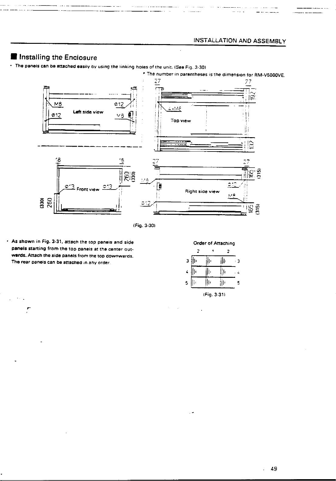
6 Top panel, Side panel, Rear panel
As this system is of the rear projection type, it must be enclosed to avoid exposure to external light. (Fig.3-29)
Side panel
Top panel
Side panel
(Fig. 3-29)
Rear panel
48
Page 50
Page 51

INSTALLATION AND ASSEMBLY
3' Attaching the Multi Projection Unit (RM-V4000V) to the Projection Cabinet (RMF-
V4011R)
The figure shows the assembling procedure of the left attachment. Assemble the right attachment in the same way. The parts
on the right side of the screen are R and those on the left side are L from the view point against the screen.
(1) Attach the attachments R and L (BNG1173, 1174) to the
front of frames R and L (BNG1207, 1208) using the
screw (M5 ×15).
(2) Insert the claws of holders R and L (BNG1150, 1151)
into the slits of frames R and L, rotate them as shown
in the figure, and attach using the screws (M5 × 15). (2
pieces × 2 locations).
(3) Insert the claws of the attachments R and L into the
rear slits of the multi-projection unit, and attach using
the screws (M5 × 15). (1 piece × 2 locations).
*Drop the screw-lock fluid to screws so as not to
loosen.(Right and left)
(4) Attach the parts assembled at steps (1) and (2) onto
the multi-projection unit. Attach the attachments R
and L to frajmes R and L.
using the screw (M5 × 15) as shown in the figure, and
attach the attachments R and L to the rear of the projection unit using the screws (M5 × 50).
(2 screws × 2 locations).
50
Page 52

4
INSTALLATION AND ASSEMBLY
(5) Paste spacer A (BMR1073) to the top board of the
multi-projection unit and spacers B (BMR1074) to the
two sides at the
23
position shown in the figure after
peeling off the seal.
* Paste after adjusting the
center of the top board
to that of spacer A.
* Paste without cover-
ing the fan.
(7) Attach the attachments R and L to the unit through the
top board of the unit using the screws (M6 × 20) and
then attach attachments R and L to the unit from the
back using screws (M6 × 20). (2 screws × 2 locations).
*Drop the screw-lock fluid to screws so as not to loosen.
(4 points)
(6) Insert the multi-projection unit from the rear of the
unit in this state.
Unit
(8) Check the Focus and reajust if necessary.
(9) Attach the cover (BNE1012) to the top board of the unit
using the four screws (M5 × 15).
Screw (M5 × 15)
51
Page 53

INSTALLATION AND ASSEMBLY
(10) Attach the adjuster (BEF1011) attached with a nut
(M8) to the rear holders R and L (BNG1205 and 1206).
(12) Attach each rear panel (BMR1069, 1070, 1071, 1072) to
the unit and the rear holders R and L using the screws
(3 × 8). Furthermore, to cover up the gap at the top of
the projection unit, paste the hinder panel (BMR1075)
over the top board and projection unit.
(11) While tilting the parts assembled at step 10, insert it
into the holes on the shoulder of the multi-projection
unit and attach with the screws (3 × 12). (2 screws × 2
locations). Furthermore, pull up the adjuster to the top
of the unit while rotating it, and pull down the nut to
the rear holders R and L while rotating it to secure the
projection unit.
* Tighten the nuts tightly.
[After Completion]
4' Mounting the Projection Cabinet (RMF-V4011R)
Projection cabinet can mount to use the conventional method. For details, refer to the RM-V2000A technical manual.
52
Page 54

INSTALLATION AND ASSEMBLY
5. SPECIAL INSTALLATION
(1) Wall inset
• If removing the screen after installing the system, the person must go behind the screen (diagonally shaded part of the
figure). Therefore when insetting the unit in the wall, careful take this into account before installation.
Screen
• When fixing the screen into the wall, space for placing your hand inside the wall at the top, bottom, right, and left will be
required in addition to the above in order to attach and remove the screen.
(2) Diagonal installation
• This system cannot be placed facing upwards or downwards and diagonally. Always place it horizontally.
However, Multiprojection unit (RM-V4000V/V5000V) alone can be tilted at the top, bottom, left, and right up to 90 deg.
Installation of special order screens and cabinets should also become possible in the near future.
(3) Architrave processing
• When enclosing the screen with a frame, etc., add 15 mm to the dimensions of the assembled screen at the top, bottom, left,
and right.
* Perform framing constructions after assembling the screen.
15 mm
15 mm
15 mm
15 mm
(Fig. 3-32)
• If light leaks from the rear space after constructions, place a blind plate over the rear.
• No one should climb onto the top board.
(4) Upside down installation
• Not possible
(5) Hanging from ceiling
• Not possible
53
Page 55

CHAPTER 4. ADJUSTMENTS
1. ADJUSTMENT PREPARATIONS
(1) Wiring
1 Connection of Power Supply
• The power supply can be connected to up to 3 units in a series using the AC outlets of Multi projection units. Connect the
three units as one system to the external outlet.
• The AC plug of Multi projection unit is a 3P with a ground pin. When connecting it to a normal outlet, use an exclusive 3P AC
adapter.
• The AC plug of Multi projection unit is a 3P with a ground pin. To prevent electric shocks, connect the ground pin to the
ground when connecting the power supply.
2 Connection of signal cable
• Use coaxial cables. Normally, if less than 15m, use 3C-2V. If less than 30m, use 5C-2V.
The signal transmission equipment and Multi projection units should be as close as possible to each other.
3 Connection of ABL link cable
• By connecting the ABL link cables in cascade form, control signals (RS-232C, remote control signal) can be transmitted to all
the units.
Personal Computer
or
Remote control
RS-232C
Multi Projection
Unit
OUT
Multi Projection
Unit
IN
OUT
Link cableLink cable
Multi Projection
Unit
IN
OUT
(2) Wiring Handling
• Except for short-term installations such as events, etc., in normal long-term installations, adjust the length of the wiring
appropriately taking into consideration the overall route to be wired.
• Make sure the connection terminals are not subjected to direct weight and force. Tie the wires up in short-term use and bind
them up properly in long-term use.
(3) Aging
• After turning on the power, input the 100% white signal or moving images, and perform aging until Multi projection unit
stabilizes (about 1 hour). If adjustments are performed without performing aging, as Multi projection unit will warm up and
stabilize, convergence and white balance will become incorrect.
54
Page 56

Page 57

Page 58

ADJUSTMENTS
When TV SYSTEM=AUTO
<VIDEO, Y/C Input)
• Selects the convergence memory from MEMORY-1 or MEMORY-2 automatically according to the signals input (NTSC/PAL).
<RGB Input>
• Automatically selects the convergence memory as follows.
For NTSC input:MEMORY 1
For PAL input:MEMORY 2
Horizontal frequency 20 kHz to 28 kHz input:MEMORY 3
Horizontal frequency 28 kHz to 35 kHz input :MEMORY 4
When TV SYSTEM=NTSC
• The convergence memory is always set to MEMORY 1 regardless of the input signal.
When TV SYSTEM=PAL
• The convergence memory is always set to MEMORY 2 regardless of the input signal.
In standard settings, MEMORIES 1 to 4 are selected as described above, but MEMORIES 5 to 7 can be selected if preset using
the remote control or commands of the Personal Computer.
When the input signal is NTSC only or PAL only, by setting the TV SYSTEM to NTSC or PAL, smooth input switching (no
image distortion) will be possible.
Normally, no problems will be encountered with the above method. But if two or more types of signals are input to the same
input function, convergence adjustment has to be performed according to the respective input source. (For example, when
there is signal phase difference in each input source, when connecting several PCs and switching from outside, etc.). In such
cases, use convergence adjustment memories 5 to 7 (MANUAL 1 to 3). The 5 to 7 convergence adjustment memories can be
switched from outside using the Personal Computer.
Finally, examples of main uses by the system of these units are provided below.
For details of how to set the convergence memory (specific example), refer to ”3. Examples of Main Uses of Cube System”.
57
Page 59

ADJUSTMENTS
(3) White Balance Adjustment Memory
ADJUSTMENTS has altogether six white balance adjustment memories.
Color mode 1 (Normal)
Color mode 2 (Re-expose)
Four memories can be actually adjusted except the factory shipment memory. The factory shipment memory contains the
normal white balance adjustment data and re-expose white balance adjustment data.
By setting to color mode 1 using the rear panel switch, etc., the white balance adjustment data can be switched by synchroniz-
ing with input switching. This is the same for color mode 2. If it is necessary to change color modes 1 and 2 using the input
function, connect the PC and switch each time it is necessary.
VIDEO, Y/C input memory
RGB input memory
Factory shipment memory
VIDEO, Y/C input memory
RGB input memory
Factory shipment memory
(4) Combined Use of Remote Control and Personal Computer
Although it is possible to connect both the remote control (RU-V107) and Personal Computer, adjustments cannot be per-
formed using both at the same time.
Remote control, Personal Computer commands and rear panel switches operated the latest are given priority. When the
adjustment mode is set by the Personal Computer while adjusting with the remote control, the adjustment mode will be set by
the Personal Computer, disabling adjustments to be performed using the remote control. If the adjustment mode is set by the
remote control using adjustments by the Personal Computer, adjustments by the Personal Computer will be disabled. Fur-
thermore, if the rear panel switches are operated when the adjustment mode is set by the remote control or Personal Com-
puter, the adjustment mode is exited and the rear panel switches operations are started.
(5) Memory of Adjustment Data and Settings
When adjustments are ended in the adjustment mode such as convergence, white balance, etc., always exit the adjustment
mode (AJN for Personal Computer, ADJ OUT key for remote control). If the power is turned off (AC OFF) without exiting the
adjustment mode, a part of the adjustment data will not be preserved in the memory.
The input function, MULTI ON/OFF (peripheral light amount switching), COMBINATION ON/OFF (ABL link switching), COLOR
MODE 1/2 (white balance switching), TV SYSTEM setting, and convergence memory state setting will be preserved in the
memory only when the power is turned off using the remote control, command of a Personal Computer (POF) or the rear
panel tact switch. The AC ON/OFF will not allow data to be preserved in the memory.)
When starting or stopping the system by AC ON/OFF in an installation condition for demonstration, use this method to
preserve the conditions in the memory first.
58
Page 60
ADJUSTMENTS
(6) Giving IDs
When several Multi projection units are used to compose the 9 screens or 16 screens (multi-screen), the ID is used to differen-
tiate between Multi projection units. When the units are given IDs, by connecting the ABL link cable, commands can be
transmitted by specifying the ID, and it is possible to operate only Multi projection unit corresponding to that ID by remote
control operations.
<Giving IDs using Personal Computer>
Commands: IDC (IDC CLEAR) ;Clears the ID given
IDS (ID SET) ;Gives an ID
The IDS is valid only when no ID has been given. It will be valid from units nearest to the personal
computer (remote control).
(Example) 4 screens • When giving IDs first using Personal Computer.
Personal Computer
**AJY
11 IDS
↓
**AJY
12 IDS
↓
**AJY
21 IDS
↓
**AJY
22 IDS
By sending commands in this order, IDs can be given to each Multi Projection Unit.
The characters that can be used for the IDs are 0 to 9 and A to F, and * (capital and small letters are not differentiated).
The * can be used in the following way.
**IDC :Clears IDs given to all units
*1AJY :Only units which have IDs whose 2nd digit is 1 enter the adjustment mode.
2*IN1 :The input function of only units which have IDs whose 1st digit is 2 is set to VIDEO.
Multi Projec-
tion Unit
ID=11 ID=12
Multi Projec-
tion Unit
Multi Projec-
tion Unit
ID=21 ID=22
Multi Projec-
tion Unit
59
Page 61

ADJUSTMENTS
<Giving IDs Using the Remote Control>
[1] Enter the adjustment mode.
[2] The main menu will be displayed. Press the
Select ”1. ID CLEAR/SET/SELECT”
[3] Check that the ID display at the top left of the screen is “– –” and press the
Select “1.ID SET”.
If an ID has already been given, press the
adjustment mode.” and give the ID.
[4] As the ID input standby state is set, press the
[5] To use the multi-screen unit, return to “[1] Enter the adjustment mode.” and given an ID to the next unit.
<Precautions for Giving IDs using the Remote Control and Personal Computer>
Communication cannot be performed with units connected using the ABL link cable, after units whose IDs have been
cleared. When the command “** IDC” shown in the figure on the previous page is performed, only the first unit can be
controlled. Using the command “11 IDS” will enable the 2nd unit and onwards to be controlled.
When IDs are set as this, the unit connected next can be controlled.
1
key.
1
key.
0
key, select “0. ID CLEAR” of the main menu, return to “[1] Enter the
to
F
keys, and input the ID.
to
0
9
A
,
60
Page 62

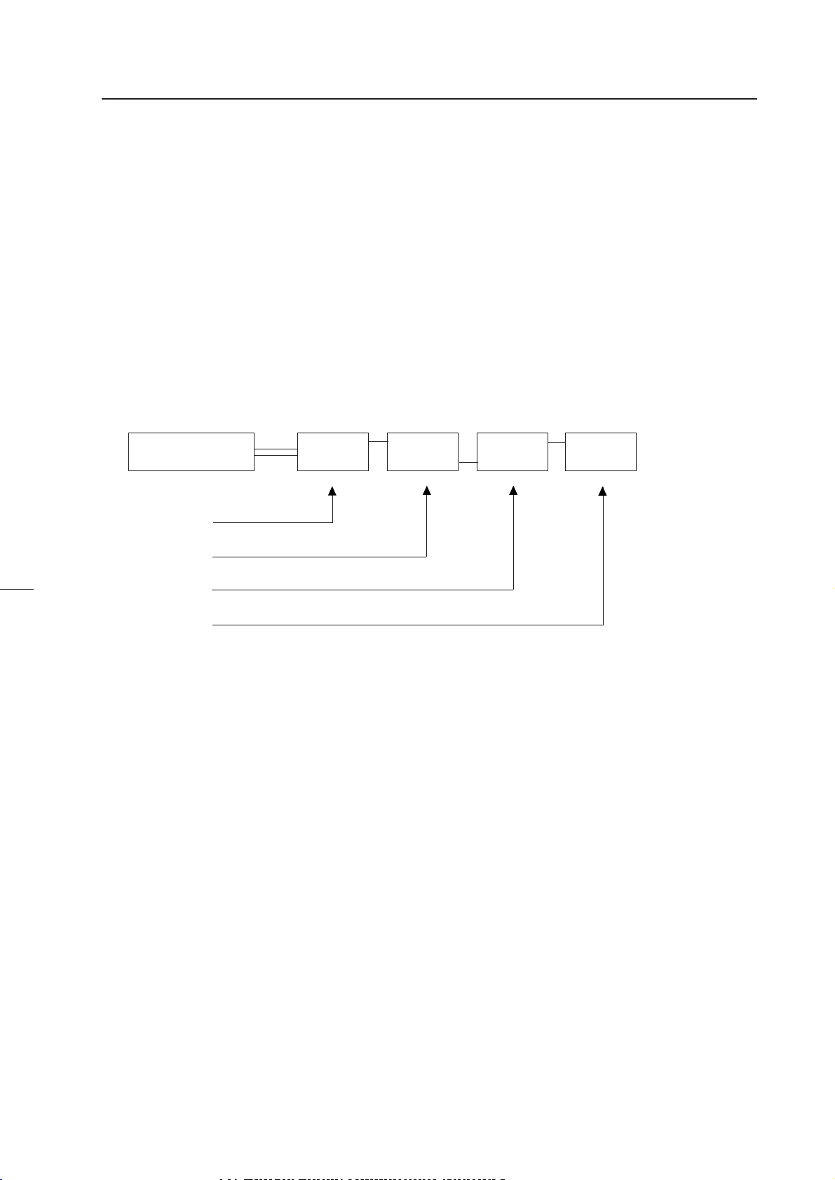
3. EXAMPLES OF MAIN USES OF CUBE SYSTEM
(1) Expansion/Individual Switching at Multi Video Processor Side-
General example of RM-V2000 series
ADJUSTMENTS
Source
Input Function) Fixed mainly at RGB
TV SYSTEM) Fixed at NTSC or PAL
Converter data required at display) One
Multi Video
Processor
Cube
(2) When Switching the Cube Input Function-Display example expected on RM-V4000V
system
Expanded
NTSC
Source
Personal
Computer
Multi Video
Processor
Individual
Y/C
Cube
RGB
Input Function) By switching Y/C↔RGB, switches
expansion/individual (video distortion is great)
TV SYSTEM) Composite or Y/C signal system Fixed at NTSC
RGB AUTO
Converter data required for display) Composite signal system-One
RGB-One
61
Page 63

ADJUSTMENTS
(3) When Switching Source Inputs to Multi Video Processor (1)-
When using Pioneer's new Multi Video Processor
NTSC
Expanded
Personal
Computer 1
Personal
Computer 2
Input Function) RGB
TV SYSTEM) AUTO
Converter data required for display) One
Multi Video
Processor
*The phase difference of each input source can be adjusted at the Multi Video Processor side.
*When switching between the same NTSC, it is needed to switch by CUBE side.
NTSC
Expanded
RGB
Cube
(4) When Switching Source Inputs to Multi Video Processor (2)-
When using Pioneer's Multi Video Processor
LDP-1
LDP-2
* There is phase difference
between LDP1 and 2
Input Function) Y/C
TV SYSTEM) Fixed at NTSC
Converter data required for display) Two
* For example, adjust LDP-1 with MEMORY1 and LDP-2 with MEMORY 5 (or 6 or 7) and switch
data when switching LDP
Multi Video
Processor
* Only one image
frame data
NTSC
Y/C
Expanded
Cube
62
Page 64

ADJUSTMENTS
(5) When Using Two Multi Video Processors without Frame Adjusting Function
Multi Video
Processor 1
Multi Video
Processor 2
Input Function) RGB
TV SYSTEM) AUTO
The converter data required for display) Two
* MEMORY1/2 is automatically switched by the microprocessor
Expanded
(Or synchronize with the switching of Multi Video Processor 1/2 and switch NTSC
fixing/PAL fixing)
(6) When Single Screen is Used
NTSC
Cube
RGB
PAL
Expanded
VGA
Cube
RGB
MAC
Input Function) RGB
TV SYSTEM) AUTO
Converter data required for display) Two
* For example, adjust VGA with MEMORY4 and MAC with MEMORY 5 (or 6 or 7), and switch
the signal selection data
63
Page 65

ADJUSTMENTS
(7) When Switching the Source Input to the Multi Video Processor
NTSC
Personal
Computer 1
Personal
Computer 2
Input Function: RGB
TV SYSTEM: AUTO
Converter data required for playing: Three
Expanded NTSC
ƒH=31.75 kHz
Multi Video
ƒH=31.75 kHz
ƒH=35 kHz
For example, set as follows, and switch the data to input using RS-232C.
Expanded NTSC:MEMORY 4
Personal computer 1:MEMORY 5
Personal computer 2:MEMORY 6
Processor
ƒH=35 kHz
RGB
Cube
64
Page 66

ADJUSTMENTS
4. SCREEN ADJUSTMENTS
(1) Adjustment Flowchart
The following shows the order for performing the adjustments generally required in the setup of the multi-projection system.
For details, see the descriptions on the next page and later.
1 Give ID
↓
2 Adjust the size of each screen
↓
3 Adjust the convergence of each screen
↓
4 Adjust the joining of the screens
(Adjust with the multi-video processor)
↓
5 Check that there is no information missing and color deviation on the moving image.
If information is missing or color has deviated, return to 2 and readjust.
↓
6 Adjust the white balance of each screen.
↓
7 Adjust the ABL level
↓
8 Check the ABL level and white balance using the video actually transmitted.
If there is deviation, return to 6 and readjust
↓
9 Adjust the color tone using the video actually transmitted.
↓
0 Recheck 6 to 8
65
Page 67

Page 68

ADJUSTMENTS
(3) Convergence Adjustment Contents
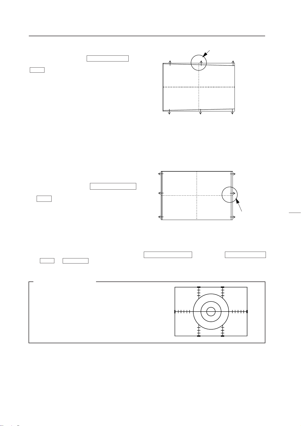
1 Measurement of screen center
The center can be found easily by pasting threads in the
spaces of the protection panels at the screen frame.
The & numbers correspond to the numbers in the flow-
chart.
2 Adjustment signal input
For adjusting size...Monoscope, etc.(EX.LD Test disc GGV1013, FRAME NO. 18001)
For screen joining, linearity, color adjustment...Use adjustment signals such as , cross-hatch, etc.
(EX.LD Test disc GGV1013, FRAME NO. 14401)
If signals are created in the multi video processor, use them.
For RGB inputs, generate the adjustment signals conforming to the above using the models actually used (PC, etc.), and check
them via the expander actually used.
Note
Depending on the user memory used, the image may
become distorted as shown in the figure on the right.
In this case, before adjusting the center, adjust H BLK R
and H BLK L first.
Marked color deviation
67
Page 69

ADJUSTMENTS
3,4,7 center adjustment
Set to only green and adjust the center with V PHASE
H PHASE .
When MULTI ON, as V PHASE does not
move, adjust it at the splitter side.
If not possible, adjust with V STATIC
NOTE
Do not adjust the center using convergence such as
GH STATIC GV STATIC
Green POINT CONVER MODE , etc.
Considerable load will be imposed on the adjustment
circuit, causing malfunctions.
Center
V PHASE
(V STATIC when
MULTI ON)
H PHASE
Three colors R, G, B move together
GH STATIC
GV STATIC
Only Green moves
The center adjustment by H PHASE V PHASE adjusts the timing for displaying video signals and therefore current is not
supplied to the deflection york.
Current is on the other hand supplied to the convergence york in the center adjustment by convergence such as GH STATIC
GV STATIC GREEN POINT CONVER MODE , etc. and therefore imposes load on the circuit.
68
Page 70

Current is also supplied to the vertical deflection york with
V STATIC . If supplied excessively, distortion will occur as
shown in the right figure.
No distortion occurs in adjustments by V PHASE .
ADJUSTMENTS
69
Page 71

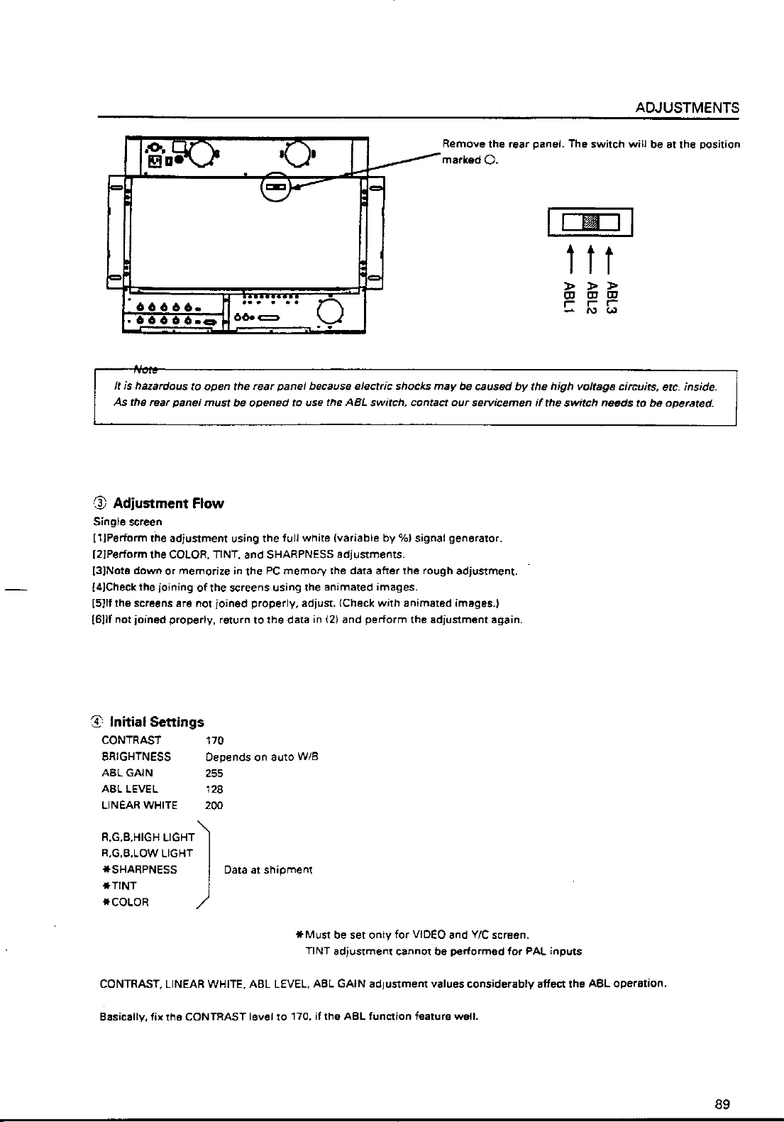
ADJUSTMENTS
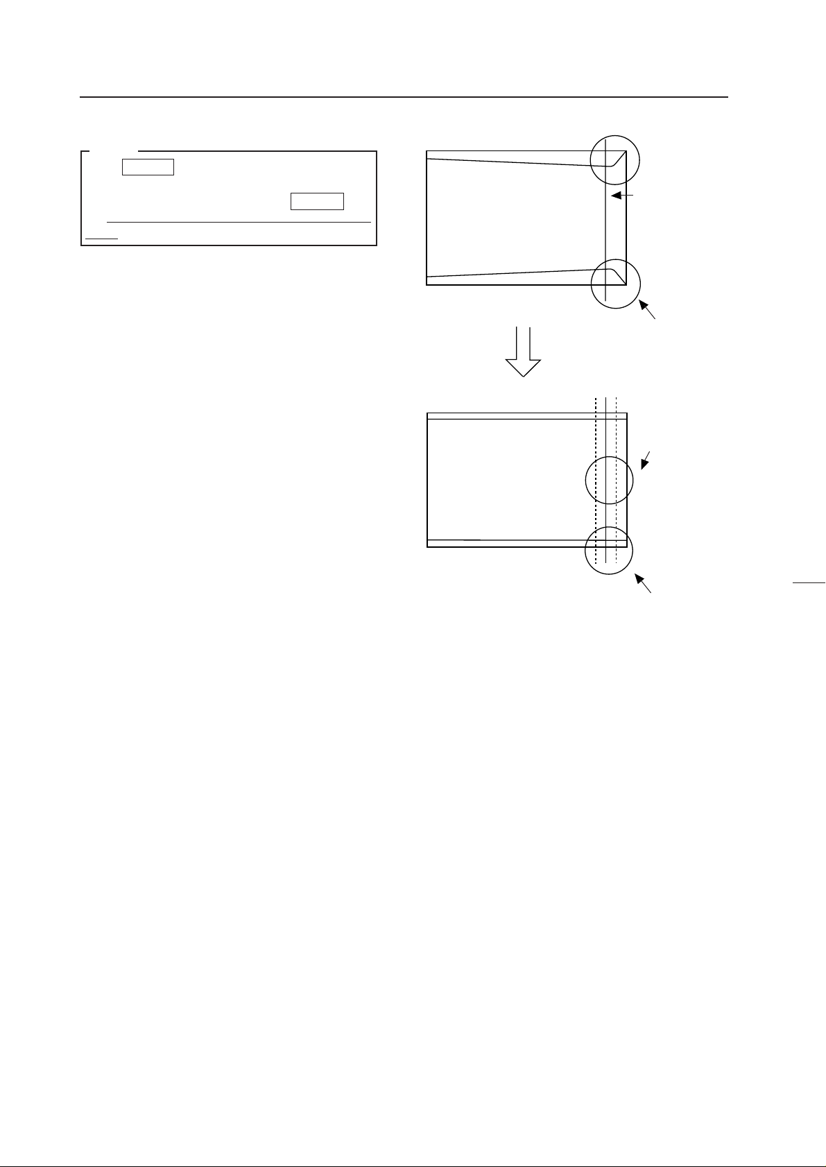
Explanation of H BLK L and H BLK R Adjustments
H BLK L and H BLK R adjustments are performed to obtain the optimum convergence adjustment wave form when the
display range changes due to changes in the H SIZE and frequency.
Video signal
Display range
Convergence
adjustment
wave form
Video signal
Convergence
adjustment
wave form
Display
range af-
ter size
changed
Color deviation
When size is increased with H BLK L and H BLK R not ad-
justed.
No color deviation
Convergence
adjustment
wave form
70
Adjustment by
H BLK L
Image after H BLK L and H BLK R has been adjusted.
Adjustment by
H BLK R
Page 72

5 H BLK R Adjustment
Output all three colors R,G,B, observe
the right side of the screen , and adjust with H BLK R so
that the color stops deviating.
ADJUSTMENTS
RGB
Observe
here
RGB
When H BLK R adjustment is not properly performed
BGR
71
Page 73
ADJUSTMENTS
NOTE
When H BLK R is adjusted so that the three colors
R,G,B do not deviate, if the horizontal line distortion
shown in the right figure occurs, move H BLK R until
the distortion disappears with color deviation maintained.
No color deviation
Sudden distortion
Color deviation
No distortion
72
Page 74

ADJUSTMENTS
6 H BLK L adjustment
Output all three colors R,G,B, observe the
left side of the screen , and adjust with H BLK L so that
the color stops deviating.
Observe
here
NOTE
There are points at which the screen does not move even though the H BLK L value changes. This is not a malfunction.
NOTE
After adjusting H BLK L , the left side of the screen
may be smaller than the right side of the screen. As the
pPOINT CONV, MODE of the procedure will be performed later, ignore it now.
RGB
RGB
73
Page 75
ADJUSTMENTS
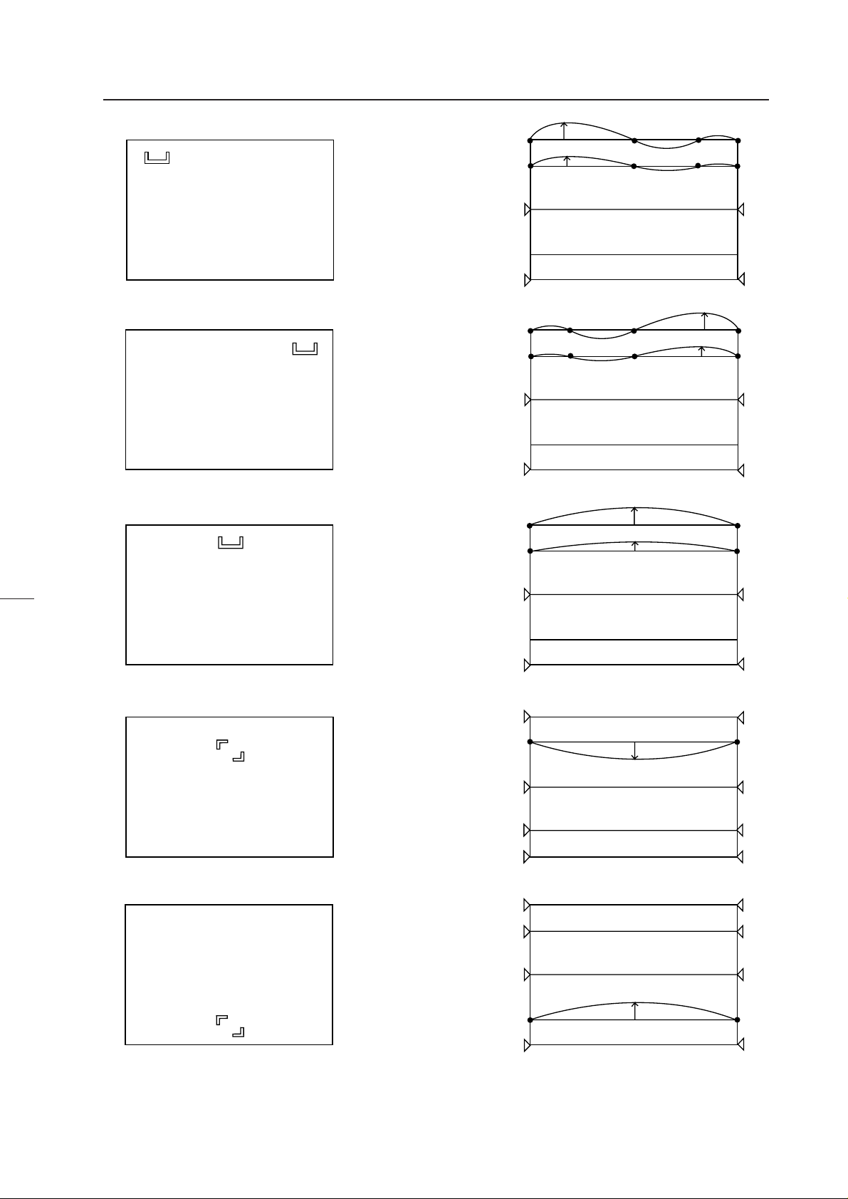
9 V SIZE adjustment
Set to only green, observe the top part of the screen , and
adjust the data amount in the vertical direction using
V SIZE .
Do not observe the bottom part of the screen.
8 H SIZE adjustment
Set to only green, observe the right side of the screen ,
and adjust the data amount in the horizontal direction us-
ing H SIZE .
Observe here
Do not observe the left side of the screen.
Observe
here
9’ V SIZE LINEARITY Adjustment
Those familiar with the convergence adjustment can adjust the bottom part of the screen in addition to the top part of the screen
using V SIZE and V LINEARITY .
Reference Information
The horizontal 92% and vertical 93% positions in NTSC
inputs are the positions shown in right figure, for Laser
4
3
2
1
4
3
2
1
Disc test disc GGV1013 monoscope signal (frame No.
14401).
6
54321
12345
1
2
3
4
1
2
3
4
6
74
Page 76

Page 77

ADJUSTMENTS
Movement of screen by point convergence adjustment
Movement of screenOSD display
Observe here
Use especially when adjusting the horizontal size of the left side of the screen in adjustment step p .
In addition, there are three other area adjustments.
76
Page 78

ADJUSTMENTS
In adjustment step q , observe the external part of the screen, adjust the 16 adjusting points there, taking note of linearity in
the peripheral area such as joining with other screens, crosshatch, etc.
(Ignore the distortion inside the screen.)
In adjustment step w , adjust the inside of the screen and produce linearity.
The following are examples of adjusting points in point convergence adjustments and their movements on the screen.
77
Page 79

ADJUSTMENTS
Displayed OSD
Movement on screen
78
Page 80

ADJUSTMENTS
79
Page 81

ADJUSTMENTS
80
Page 82
ADJUSTMENTS
81
Page 83

ADJUSTMENTS
82
Page 84

ADJUSTMENTS
NOTE
If only one point is moved greatly in the point conver-
gence mode, it may not move in areas smaller than the
desired adjusting area.
In this case, adjust while moving the other points
slowly.
Does not move to the set position
5 2
4 1
6 3
83
Page 85

Page 86

Page 87

Page 88

Page 89

Page 90
Page 91

Page 92
Page 93

Page 94

Page 95

Page 96
Page 97

Page 98
Page 99

Page 100
 Loading...