

Page 1

CLASS D MONO AMPLIFIER
AMPLIFICATEUR MONO DE CLASSE D
ENGLISH
FRANÇAIS
ESPAÑOL
Owner’s Manual
PRS-D1200SPL
Mode d’emploi
Page 2

Contents Before Using This Product
Before Using This Product ...................... 1
Information to User .......................................... 1
Important .......................................................... 1
Product Registration .......................................... 2
About This Product .......................................... 2
CAUTION ........................................................ 2
WARNING ........................................................ 2
Setting the Unit .......................................... 3
MODE SELECT Switch .................................. 3
Bass Boost Frequency Control .......................... 3
Bass Boost Level Control .................................. 3
Terminal Cover ................................................ 3
Cut Off Frequency Control for LPF .................. 3
Gain Control ...................................................... 4
BFC (Beat Frequency Control) Switch ............ 4
HEAT Indicator ................................................ 4
PROTECT Indicator .......................................... 4
Power Indicator ................................................ 4
Subsonic Select Switch .................................... 4
Setting the Gain properly .................................. 5
Connecting the Unit .................................. 6
Connection Diagram ........................................ 7
Solderless Terminal Connections ...................... 8
Connecting the Speaker Output Terminals ...... 8
Connecting the Power Terminal ........................ 9
Setting the Gain for synced amplifier ............ 10
Connecting the Speaker Wires ........................ 10
Installation ................................................ 15
Attaching the Bass boost remote control ........ 15
Example of installation on the floor mat
or on the chassis ...................................... 16
Replacing the terminal cover .......................... 16
Changing the Direction of the Badge .............. 16
Additional information ............................ 17
Troubleshooting .............................................. 17
Specifications .......................................... 18
Thank you for purchasing this PIONEER
product. It is designed to give you many
years of enjoyment.
PIONEER SUGGESTS USING A PROFESSIONAL INSTALLER DUE TO THE
COMPLEXITY OF THIS PRODUCT.
Please read all instructions and WARN-
INGS in this manual before attempting
operation. Should you have any questions,
contact your nearest Pioneer authorized
dealer or installation specialist.
Information to User
Alteration or modifications carried out
without appropriate authorization may
invalidate the user’s right to operate the
equipment.
Important
The serial number of this amplifier is written on the bottom of the unit. For your
own security and convenience, write it
down on the enclosed warranty card. Keep
the card handy for future reference.
After-sales service for Pioneer
products
Please contact the dealer or distributor from where
you purchased the product for its after-sales service (including warranty conditions) or any other
information. In case the necessary information is
not available, please contact the companies listed
below:
Please do not ship your product to the companies
at the addresses listed below for repair without
advance contact.
7 U.S.A.
Pioneer Electronics (USA) Inc.
CUSTOMER SUPPORT DIVISION
P.O. Box 1760
Long Beach, CA 90801-1760
800-421-1404
7 CANADA
Pioneer Electronics of Canada, Inc.
CUSTOMER SATISFACTION
DEPARTMENT
300 Allstate Parkway
Markham, Ontario L3R OP2
1-877-283-5901
For warranty information please see the Limited
Warranty sheet included with your product.
1
Page 3
Product Registration
ENGLISH
WARNING
Visit us at the following site:
1 Register your product. We will keep the details of
your purchase on file to help you refer to this
information in the event of an insurance claim
such as loss or theft.
2 Receive updates on the latest products and tech-
nologies.
3 Download owner’s manuals, order product cata-
logues, research new products, and much more.
About This Product
This product is a class D amplifier for the
subwoofer. If both L (left) and R (right)
channels are connected to the RCA input
of this product, output is mixed because
this product is a mono amplifier.
CAUTION
• Never replace the fuse with one of greater value
or rating than the original fuse. Use of an
improper fuse could result in overheating and
smoke and could cause damage to the product
and injury including burns.
• Use the supplied hexagonal wrench to tighten
screws when fastening wires to the terminal or
when changing the direction of the badge. The
use of a long, commercially available hexagonal
wrench can cause excessive torque to be applied
possibly resulting in damage to terminals and
wires.
• Handling the cord on this product or cords associated with accessories sold with the product may
expose you to chemicals listed on proposition 65
known to the State of California and other governmental entities to cause cancer and birth
defects or other reproductive harm. Wash hands
after handling.
• Always use the recommended battery wire and
ground wire, which is sold separately. Connect
the battery wire directly to the car battery positive
terminal (+) and the ground wire to the car body.
• Do not touch the amplifier with wet hands.
Otherwise you may get an electric shock. Also,
do not touch the amplifier when it is wet.
• For traffic safety and to maintain safe driving
conditions, keep the volume low enough so that
you can still hear normal traffic sound.
• Check the connections of the power supply and
speakers if the fuse of the separately sold battery
wire or the amplifier fuse blows. Detect the cause
and solve the problem, then replace the fuse with
another one of the same size and rating.
• To prevent malfunction of the amplifier and
subwoofer, the protective circuit will cut the
power supply to the amplifier (sound will stop)
when an abnormal condition occurs. In such a
case, switch the power to the system OFF and
check the connection of the power supply and
subwoofer. Detect the cause and solve the
problem.
• Contact the dealer if you cannot detect the cause.
• To prevent an electric shock or short-circuit
during connection and installation, be sure to
disconnect the negative (–) terminal of the battery
beforehand.
• Confirm that no parts are behind the panel when
drilling a hole for installation of the amplifier. Be
sure to protect all cables and important equipment
such as fuel lines, brake lines and the electrical
wiring from damage.
• DO NOT allow amplifier to come into contact
with liquids due to, for example, the location
where the amplifier is installed. Electrical shock
could result. Also, amplifier and speaker damage,
smoke, and overheating could result from contact
with liquids. In addition, the amplifier surface
and the surface of any attached speakers could
become hot to the touch and minor burns could
result.
ESPAÑOL DEUTSCH FRANÇAIS ITALIANO
NEDERLANDS
кмллдав
2
Page 4
Setting the Unit
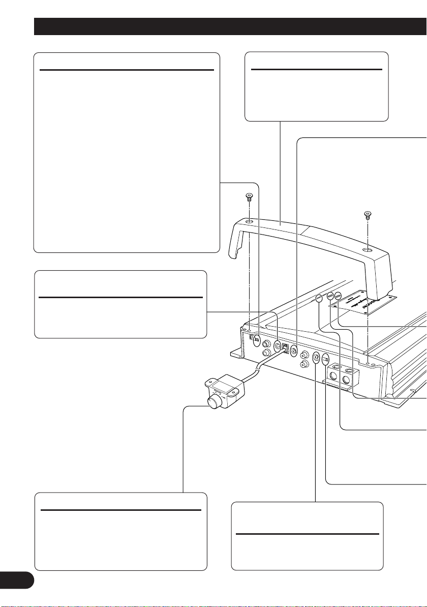
MODE SELECT Switch
You can select amplifier’s sync mode from
MASTER, SYNC and SYNC INV. Set the
MODE SELECT switch to the MASTER position when using one amplifier only. When using
synchronously connecting two or more of these
amplifiers in combination, set the first amplifier
to MASTER, and set the remaining amplifiers to
SYNC or SYNC INV according to the manner in
which they are connected. The only time the
amplifier is switched to the SYNC INV mode is
when amplifiers are synchronously connected
with the ex. bridge.
When switching to the SYNC or SYNC INV
mode, remove the screw and stopper. Remove
the screw and stopper after checking that
connections are correct. See the “Connecting the
Speaker Wires” section for details on the MODE
SELECT switch.
Bass Boost Frequency Control
You can select a bass boost frequency
from 40 Hz to 120 Hz with the bass
boost control.
Terminal Cover
Before setting up the unit, unfasten the screws with a 4 mm
hexagonal wrench and remove
the terminal cover.
Bass Boost Level Control
You can select a bass boost level from
0, 6, 9 and 12 dB.
For instruction of connecting the bass
boost remote control to the amplifier,
see the “Connection Diagram” section.
3
Cut Off Frequency Control
for LPF
You can select a cut off frequency
from 40 Hz to 240 Hz.
Page 5
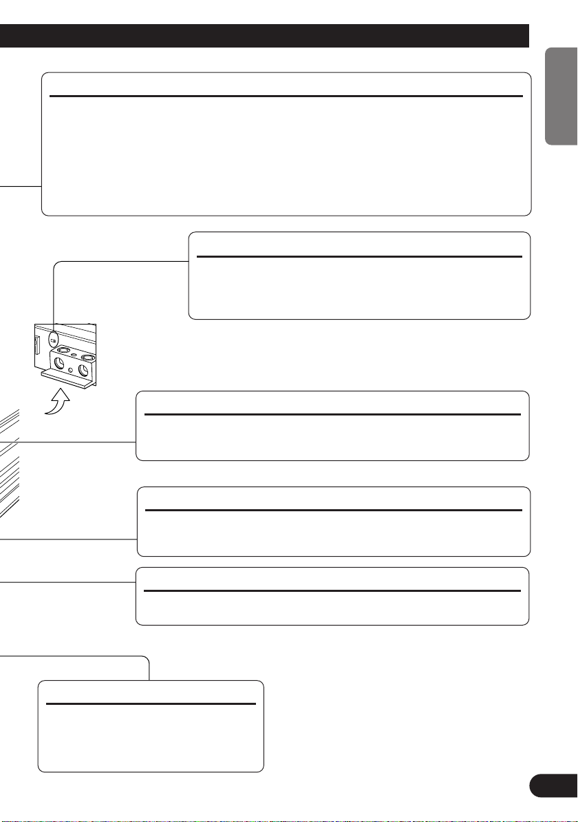
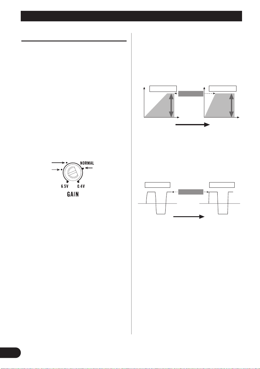
Gain Control
If the sound level is too low, even when the volume of the car stereo used along with this
power amplifier is turned up, turn gain control clockwise. If the sound distorts when the volume is turned up, turn the gain control counter-clockwise.
• When using with an RCA equipped car stereo (standard output of 500 mV), set to the NORMAL
position. When using with an RCA equipped Pioneer car stereo with max. output of 4 V or more,
adjust level to match the car stereo output level.
• For synced amplifier’s gain control, see the “Setting the Gain for synced amplifier” sec-
tion.
BFC (Beat Frequency Control) Switch
If you hear a beat while listening to an AM broadcast with
your car stereo, change the BFC switch using a small standard tip screwdriver.
HEAT Indicator (Yellow)
This indicates a problem with the amplifier. See the “Troubleshooting”
section on page 17 for details.
ENGLISH
ESPAÑOL DEUTSCH FRANÇAIS ITALIANO
PROTECT Indicator (Red)
This indicates a problem with the amplifier. See the “Troubleshooting”
section on page 17 for details.
Power Indicator (Blue)
The power indicator lights when the power is switched on.
Subsonic Select Switch
The subsonic filter cuts inaudible
frequencies below 20 Hz to eliminate
unwanted vibrations and minimize
power loss.
NEDERLANDS
кмллдав
4
Page 6
Setting the Unit
Amplifier gain
(normal)
Amplifier gain
(maximum)
Head unit volume steps
Power
Normal gain
Power
Head unit volume steps
Maximum gain
Equal power
Preout level: 2 V
(Standard: 500 mV)
Preout level: 4 V
Preout level: 6.5 V
Setting the Gain properly
• This unit is equipped with a protective function to
prevent malfunction of the unit itself and speakers
from too much output, improper use or improper
connection.
• When outputting sound at high volume etc., this
function will cut off the sound output in a few
seconds. But this is not a malfunction. When you
turn down the volume of the head unit the sound
output will be restored.
• If sound output is cut, the gain control of this unit
may be improperly set. To ensure continuous
sound output at increased volume of the head unit,
set the gain control of the amplifier to a proper
position according to the preout maximum output
level of the head unit.
Gain Control of This Unit
There is no need to decrease the volume of the
head unit and too much output is controlled.
Relationship between the gain of the
amplifier and the output power of the
head unit
• If you raise the gain of the amplifier to an improper level, only distortion is increased and the power
increases only slightly.
Signal waveform when outputting at high
volume by the gain control of the amplifier
Signal
waveform
Normal gain
Amplifier gain
(normal)
Equal power
Signal
waveform
Amplifier gain
(maximum)
Maximum gain
5
• With high output the signal waveform is distorted,
if you raise the gain of the amplifier the power
changes only slightly.
• If you decrease the volume of the head unit and
set the gain control of the amplifier to the proper
position but still the sound cuts out from time to
time, contact the nearest authorized PIONEER
Service Station.
Page 7
Connecting the Unit
CAUTION
• Disconnect the negative (–) terminal of the battery to avoid the risk of short-circuit and damage
to the unit.
• Secure the wiring with cable clamps or adhesive
tape. To protect the wiring, wrap adhesive tape
around it where they lie against metal parts.
• Do not route wires where they will get hot, for
example where the heater will blow over them. If
the insulation heats up, it may become damaged,
resulting in a short-circuit through the vehicle
body.
• The amplifier increases the load on the battery
and charging system. Make sure that the vehicle’s
alternator and battery have sufficient capacity for
this amplifier. The use of a heavy-duty battery,
parallel connection of ordinary batteries or an
energy storage capacitor is recommended.
CAUTION
To prevent damage and/or injury
• Do not ground the speaker wire directly or connect a negative (–) lead wire for several speakers.
• This unit is for vehicles with a 12-volt battery and
negative grounding. Before installing it in a recreational vehicle, truck or bus, check the battery
voltage.
• If the car stereo is kept on for a long time while
the engine is at rest or idling, the battery may go
dead. Turn the car stereo off when the engine is at
rest or idling.
• If the system remote control wire of the amplifier
is connected to the power terminal through the
ignition switch (12 V DC), the amplifier will
always be on when the ignition is on— regardless
of whether the car stereo is on or off. Because of
this, the battery could go dead if the engine is at
rest or idling.
• DO NOT connect a subwoofer with a lower
impedance than specified in the “Connecting the
Speaker Wires” section. Amplifier damage,
smoke, and overheating could result from a nonspecified connection. The amplifier surface could
also become hot to the touch and minor burns
could result.
• Make sure that wires will not interfere with moving parts of the vehicle, such as the gearshift,
handbrake or seat sliding mechanism.
• Do not shorten any wires. Otherwise the protection circuit may fail to work when it should.
• Never feed power to other equipment by cutting
the insulation of the power supply wire to tap
from the wire. The current capacity of the wire
will be exceeded, causing overheating.
• Never replace the fuse with one of greater value
or rating than the original fuse. Use of an improper fuse could result in overheating and smoke and
could cause damage to the product and injury
including burns.
• Connect either of three subwoofers to the amplifier; 1: a subwoofer with a 500 W or larger nominal input and an impedance 4 Ω, 2: a subwoofer
with a 1 000 W or larger nominal input and an
impedance 2 Ω or 3: a subwoofer with a 1 200 W
or larger nominal input and an impedance 1 Ω. If
the nominal input and impedance are out of the
above ranges, the subwoofer may catch fire, emit
smoke or become damaged.
• Install and route the separately sold battery wire
as far away as possible from the speaker wires.
Install and route the separately sold battery wire,
ground wire, speaker wires and the amplifier as
far away as possible from the antenna, antenna
cable and tuner.
• Cords for this product and those for other products may be different colors even if they have the
same function. When connecting this product to
another product, refer to the supplied manuals of
both products and connect cords that have the
same function.
ENGLISH
ESPAÑOL DEUTSCH FRANÇAIS ITALIANO
NEDERLANDS
кмллдав
6
Page 8
Connecting the Unit
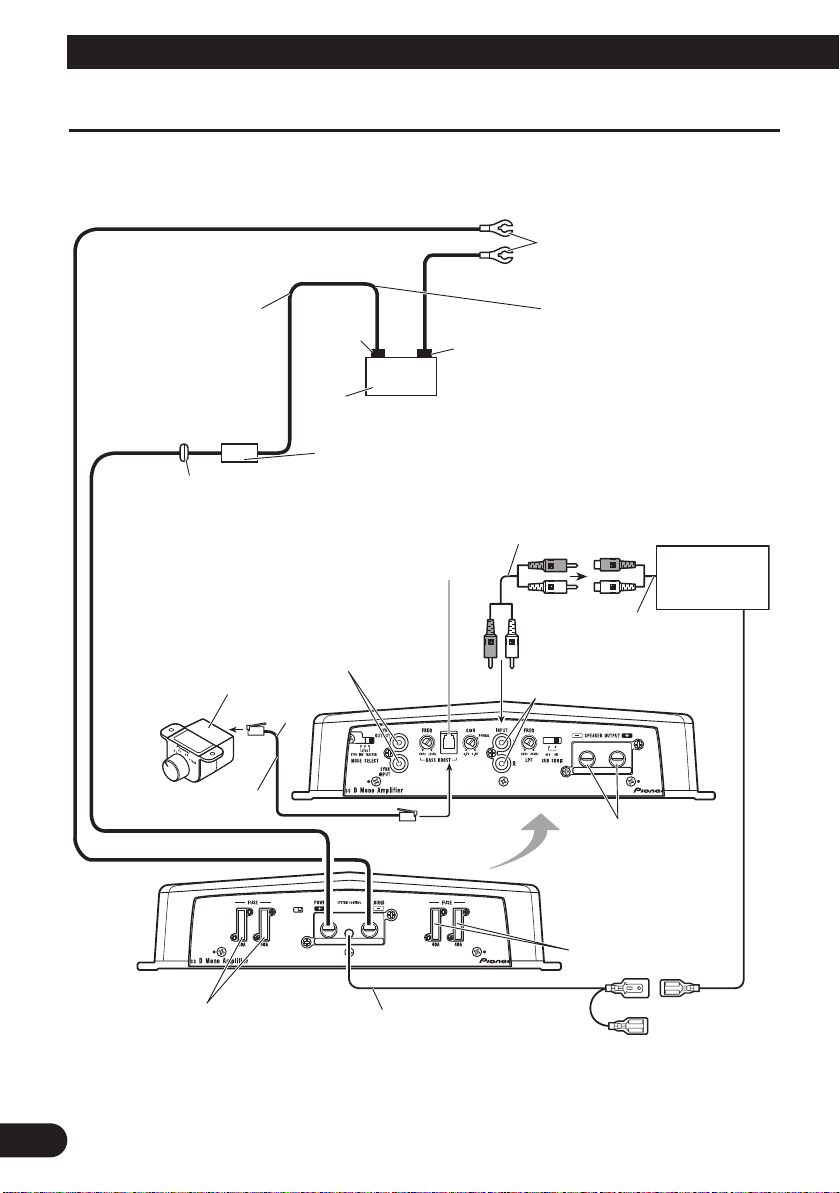
Connection Diagram
• In the case of connecting the external output from a car stereo to an RCA input, use the jack used for fullrange output. This is because the LPF of the amplifier cannot be turned OFF. If this jack cannot be used,
connect the subwoofer output jack to the RCA input.
Ground wire, Terminal (sold separately)
The ground wires must be same size
The maximum
length of the wire
between the fuse
and the positive
(+) terminal of
the battery is 45
cm.
Grommet
Jack for the bass boost remote control
Connect this jack and the bass boost remote
control with the bass boost remote control wire.
SYNC OUTPUT/SYNC INPUT jack
See the “Connecting the Speaker Wires”
section for SYNC OUTPUT/SYNC
INPUT jack connection instructions.
Bass Boost Remote Control
(19 ft. 8 in.)
Positive (+)
terminal
Battery
Fuse (200 A)
Each amplifier must be SEPARATELY fused at 200 A.
6 m
Negative (–)
terminal
as the battery wire.
Connect to metal body or chassis.
Battery wire (sold separately)
For the wire size, see the
“Connecting the Power Terminal”
section. The battery wire, the
ground wire and the optional direct
ground wire must be same size.
After making all other connections
at the amplifier, connect the battery wire terminal of the amplifier
to the positive (+) terminal of the
battery.
Connecting wire with RCA
pin plugs (sold separately).
Car stereo with
RCA output
jacks
External Output
RCA input jack
Bass Boost Remote
Control Wire
Fuse (40 A)
Reverse side
System remote control wire (sold separately)
Connect the male terminal of this wire to the system remote
control terminal of the car stereo (SYSTEM REMOTE CONTROL). The
female terminal can be connected to the auto-antenna relay control terminal.
If the car stereo does not have a system remote control terminal, connect the
male terminal to the power terminal through the ignition switch.
Speaker output terminal
See the “Connecting the
Speaker Wires” section
for speaker connection
instructions.
Fuse (40 A)
7
Page 9
Solderless Terminal Connections
• Since the wire will become loose over time, it
must be periodically inspected and tightened as
necessary.
• Do not solder or bind the ends of the twisted wires.
• Fasten while making sure to not to clamp the
insulating sheath of the wire.
• Use the supplied hexagonal wrench to tighten and
loosen the terminal screw of the amplifier.
Securely fasten the wire with the terminal screw.
However, since excessively tightening the terminal
screw of the System remote control has the risk of
damaging the wire, be careful not to tighten excessively by observing the status of the wire when
tightening.
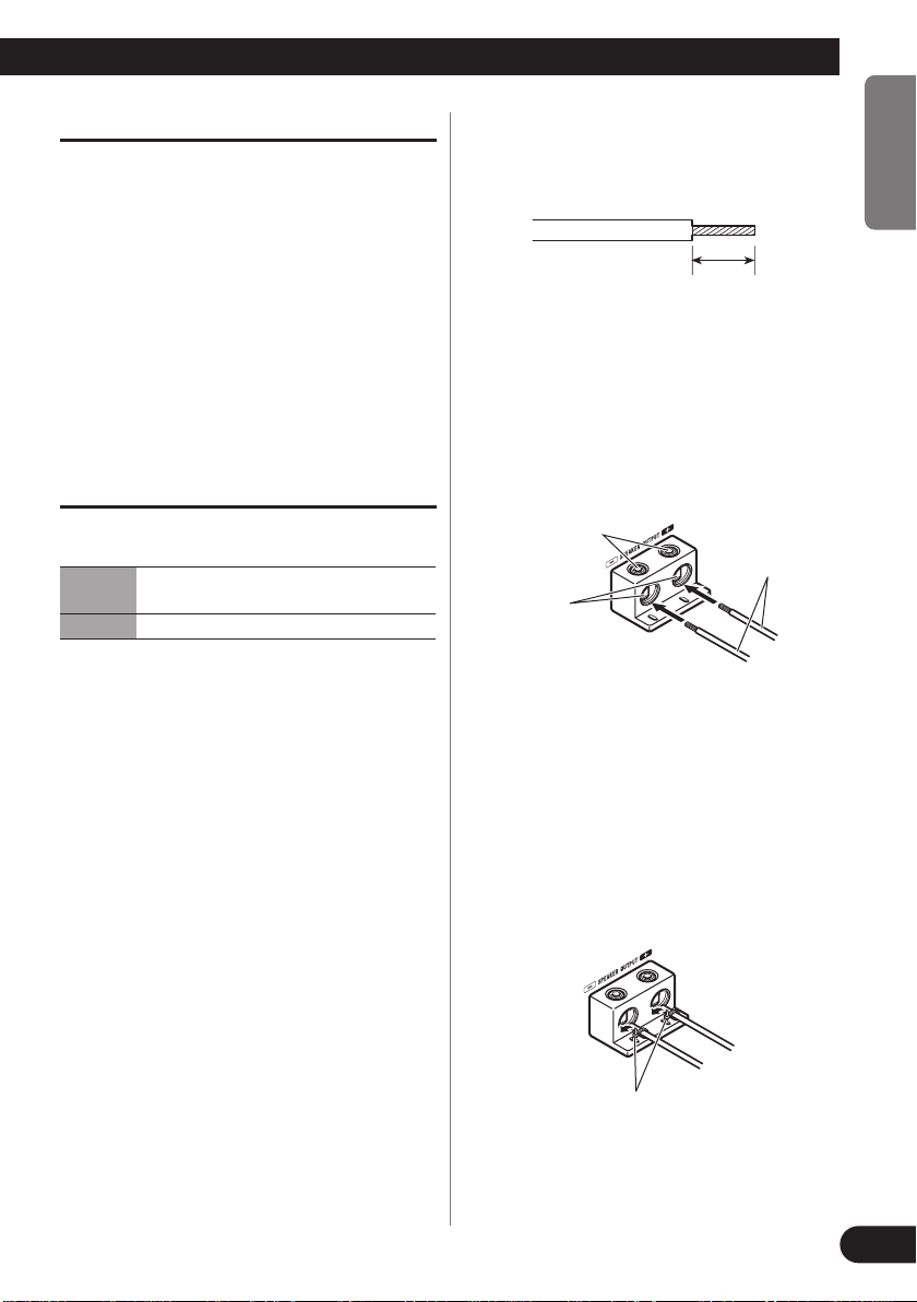
Connecting the Speaker Output
Terminals
Speaker Wire Size
Wire Length
Wire Size 8 AWG 6 AWG 4 AWG
less than 5.2 m less than 8.2 m less than 13.4 m
less than 17 ft. less than 27 ft. less than 44 ft.
ENGLISH
1. Expose the end of the speaker wires
using nippers or a cutter by about 18
mm to 20 mm (3/4 in.).
ESPAÑOL DEUTSCH FRANÇAIS ITALIANO
18 mm to 20 mm
(3/4 in.)
2. Connect the speaker wires to the
speaker output terminals.
• Fix the speaker wires securely with the termi-
nal screws.
Terminal screw
Speaker wire
Speaker
output
terminal
3. Put the wire ties in the slits and wrap
the wire ties around the wires.
• Wrap the wire tie around the wire insulation,
not the stripped wire.
• Cut off any excess portions of the wire ties.
Wire tie
NEDERLANDS
кмллдав
8
Page 10
Connecting the Unit
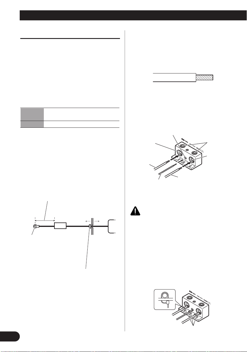
Connecting the Power Terminal
• Always use the recommended battery and ground
wire, which is sold separately. Connect the battery wire directly to the car battery positive terminal (+) and the ground wire to the car body.
• Recommended wires size (AWG: American Wire
Gauge) is as follows. The battery wire, the
ground wire and the optional direct ground wire
must be same size.
• Use a 10 AWG to 20 AWG wire for the system
remote control wire.
Battery Wire and Ground Wire Size
Wire Length less than 3.6 m less than 6.4 m
less than 12 ft. less than 21 ft.
Wire Size 6 AWG 4 AWG
1. Pass the battery wire from the
engine compartment to the interior
of the vehicle.
• After making all other connections to the
amplifier, connect the battery wire terminal
of the amplifier to the positive (+) terminal of
the battery.
The maximum length of the wire between
the fuse and the positive (+) terminal of the
battery is 45 cm (1 ft. 6 in.).
2. Expose the end of wires using nippers or a cutter.
• Battery wire, ground wire:
18 mm to 20 mm (3/4 in.)
•
System remote control wire:
14 mm to 16 mm
(1/2 in. to 5/8 in.)
3. Connect the wires to the terminal.
• Fix the wires securely with the terminal
screws.
System remote
control terminal
Power terminal
Battery wire
System remote
control wire
Terminal
screw
Ground wire
Terminal
screw
GND
terminal
Positive (+)
terminal
9
Engine
compartment
Fuse 200 A
Each amplifier must
be SEPARATELY
fused at 200 A.
Insert the O-ring rubber
grommet into the vehicle
body.
Interior of
the vehicle
Drill a 14
mm (1/2 in.)
hole into the
vehicle body.
WARNING
Failure to securely fasten the battery wire to the terminal using the terminal screws could cause the terminal area to overheat and could result in damage
and injury including minor burns.
4. Put the wire ties in the slits and
wrap the wire ties around the wires.
• Wrap the wire tie around the wire insulation,
not the stripped wire.
• Cut off any excess portions of the wire ties.
Wire tie
Page 11

Setting the Gain for synced amplifier
After connecting the speaker wires, adjust each synced amplifier’s gain control. All synced amplifiers follow
the master amplifier’s settings.
ENGLISH
Quick Setup of the Gain
Set each synced amplifier’s gain control to the NORMAL position. This setting will balance output volumes
sufficiently for most applications.
Advanced Setup of the Gain
Starting with the master amplifier, adjust the gain control on each amplifier in order.
1. Output sin wave through this system at low output level.
2. Use volt meter to measure the master amplifier’s output voltage level.
3. Use volt meter to measure the synced amplifier’s output voltage level.
4. Match the synced amplifier’s output to the master’s output using the gain control on the synced amplifier.
5. Repeat for the each synced amplifier in the proper order.
Connecting the Speaker Wires
Connect the speaker leads and set MODE SELECT switch to suit the configuration according to the figures
shown below and the next page.
• When synchronously connecting two or more amplifiers in combination, only use these amplifiers. Do not
mix these amplifiers with other amplifiers.
• When synchronously connecting two or more amplifiers in combination, set the gain control, subsonic
select switch, cut off frequency control for LPF and bass boost control on the amplifier that has been set to
MASTER with the MODE SELECT switch. These settings except for the gain control are inactive on an
amplifier which has been set to SYNC or SYNC INV. For details concerning the gain control operation, see
the “Setting the Gain for synced amplifier”.
ESPAÑOL DEUTSCH FRANÇAIS ITALIANO
NEDERLANDS
кмллдав
10
Page 12
Connecting the Unit
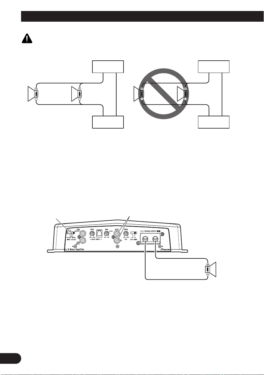
CAUTION
Amplifier
Diagram A - Proper
4 Ω
Speaker
2 Ω Bridged Mode
DO NOT install or use this amplifier by wiring speakers rated at 2 Ω (or lower) in parallel to achieve a 1 Ω (or
lower) bridged mode (Diagram B).
Amplifier damage, smoke, and overheating could result from improper bridging. The amplifier surface could
also become hot to the touch and minor burns could result.
To properly install or use a bridged mode and achieve a 2 Ω load, wire two 4 Ω speakers in parallel with Left +
and Right – (Diagram A) or use a single 2 Ω speaker.
In addition, refer to the speaker instruction manual for information on the correct connection procedure.
4 Ω
Speaker
Amplifier
Diagram B - Improper
2 Ω
Speaker
1 Ω Bridged Mode
2 Ω
Speaker
Amplifier
Amplifier
Single Amplifier
MODE SELECT switch must
be in MASTER position.
Connect to a car stereo.
For details, see the “Connection Diagram”.
• Use speakers having an impedance from 1 Ω to 8 Ω.
11
1 Ω to 8 Ω
1 200 W
(1 Ω)
Page 13
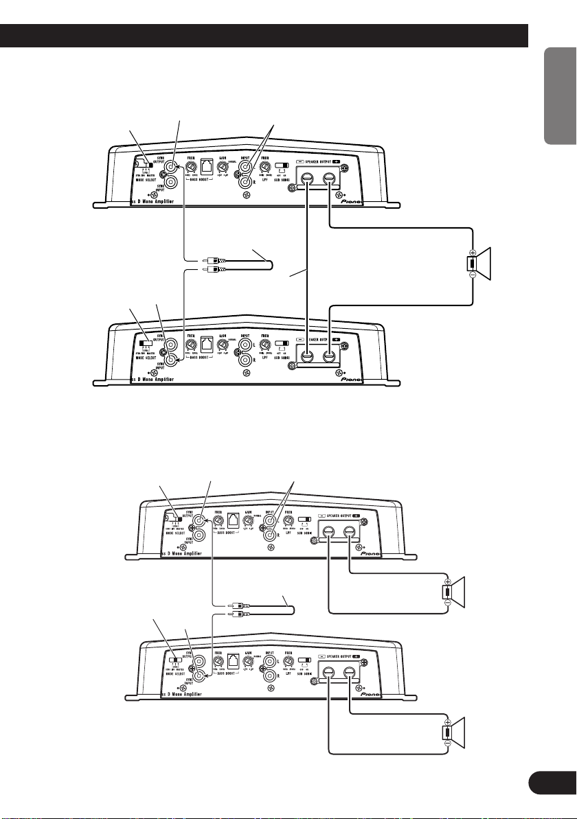
Two Amplifier (Ex. Bridge)
ENGLISH
MODE SELECT switch
must be in MASTER position.
MODE SELECT switch
must be in SYNC INV
position. Before setting
to the position, remove
the screw and the stopper.
• Only use speakers having an impedance of 2 Ω to 16 Ω. In addition, in the case of connecting multiple
speakers with a bridge, check that the synthetic impedance is at least 2 Ω.
SYNC OUTPUT
SYNC
INPUT
Connecting wire with
RCA pin plugs (sold
separately).
Connecting
speaker wire
(sold separately).
Connect to a car stereo.
For details, see the “Connection Diagram”.
Two Amplifier
MODE SELECT switch must
be in MASTER position.
SYNC OUTPUT
Connect to a car stereo.
For details, see the “Connection Diagram”.
ESPAÑOL DEUTSCH FRANÇAIS ITALIANO
2 Ω to
16 Ω
2 400 W
(2 Ω)
MODE SELECT switch
must be in SYNC position.
Before setting to the position, remove the screw and
the stopper.
• Use speakers having an impedance from 1 Ω to 8 Ω.
SYNC
INPUT
Connecting wire
with RCA pin plugs
(sold separately).
1 Ω to 8 Ω
NEDERLANDS
1 200 W
(1 Ω)
кмллдав
1 Ω to 8 Ω
1 200 W
(1 Ω)
12
Page 14
Connecting the Unit
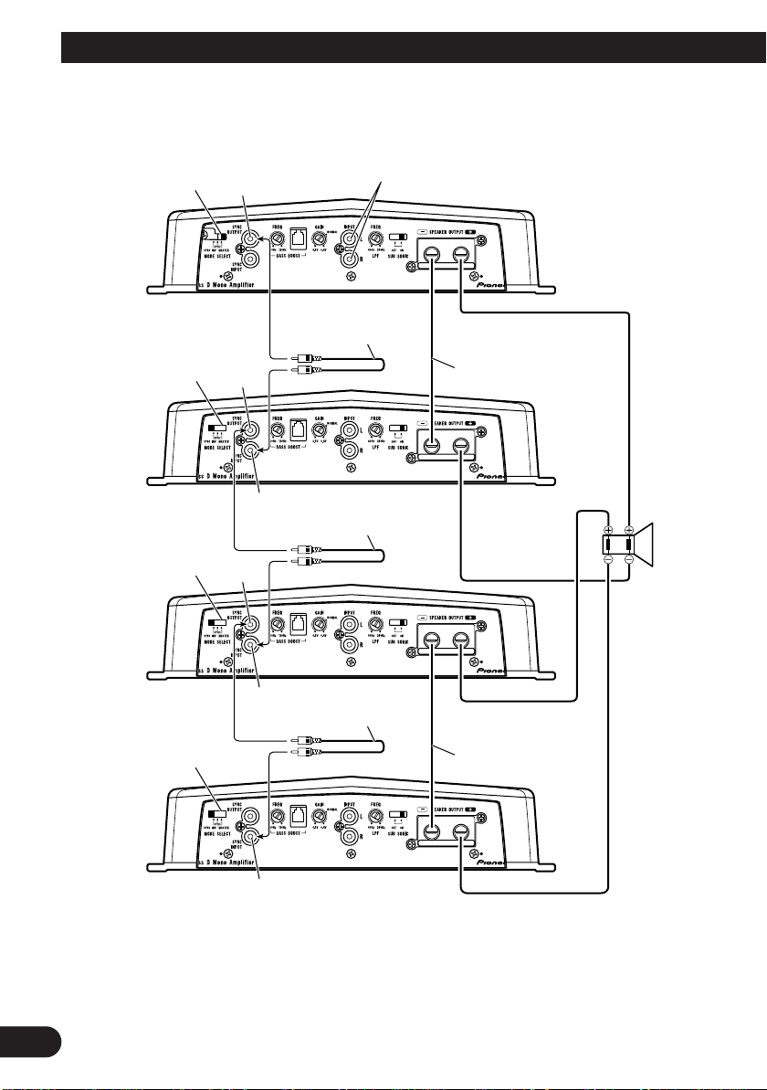
Four Amplifier (Ex. Bridge)
MODE SELECT switch
must be in MASTER
position.
SYNC
OUTPUT
Connect to a car stereo.
For details, see the
“Connection Diagram”.
MODE SELECT
switch must be in
SYNC INV position.
Before setting to the
position, remove the
screw and the stopper.
MODE SELECT
switch must be in
SYNC INV position.
Before setting to the
position, remove the
screw and the stopper.
MODE SELECT
switch must be in
SYNC INV position.
Before setting to the
position, remove the
screw and the stopper.
SYNC
OUTPUT
SYNC
INPUT
SYNC
OUTPUT
SYNC
INPUT
Connecting wire with
RCA pin plugs (sold
separately).
Connecting wire with RCA
pin plugs (sold separately).
Connecting wire with
RCA pin plugs (sold
separately).
Connecting speaker
wire (sold separately).
2 Ω to 16 Ω
4 800 W
(2 Ω DVC)
Connecting speaker
wire (sold separately).
SYNC
INPUT
• Only use speakers having an impedance of 2 Ω to 16 Ω. In addition, in the case of connecting multiple
speakers with a bridge, check that the synthetic impedance is at least 2 Ω.
13
Page 15
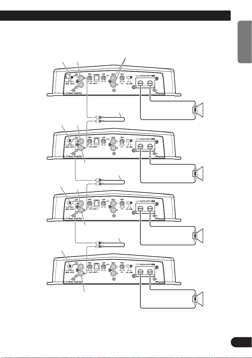
Four Amplifier
MODE SELECT switch
must be in MASTER
position.
SYNC OUTPUT
ENGLISH
Connect to a car stereo.
For details, see the
“Connection Diagram”.
ESPAÑOL DEUTSCH FRANÇAIS ITALIANO
MODE SELECT
switch must be in
SYNC position.
Before setting to the
position, remove the
screw and the stopper.
MODE SELECT
switch must be in
SYNC position.
Before setting to the
position, remove the
screw and the stopper.
MODE SELECT switch
must be in SYNC position.
Before setting to the position, remove the screw and
the stopper.
SYNC
OUTPUT
SYNC
OUTPUT
SYNC
INPUT
SYNC
INPUT
Connecting wire with
RCA pin plugs (sold
separately).
Connecting wire
with RCA pin plugs
(sold separately).
Connecting wire with
RCA pin plugs (sold
separately).
1 Ω to 8 Ω
1 200 W
(1 Ω)
1 Ω to 8 Ω
1 200 W
(1 Ω)
1 Ω to 8 Ω
1 200 W
(1 Ω)
NEDERLANDS
SYNC INPUT
• Use speakers having an impedance from 1 Ω to 8 Ω.
1 Ω to 8 Ω
1 200 W
(1 Ω)
кмллдав
14
Page 16
Installation
CAUTION
• Do not install in:
—Places where it could injure the driver or pas-
sengers if the vehicle stops suddenly.
—Places where it may interfere with the driver,
such as on the floor in front of the driver’s
seat.
• Make sure that wires are not caught in the sliding
mechanism of the seats, resulting in a short-circuit.
• Confirm that no parts are behind the panel when
drilling a hole for installation of the amplifier.
Protect all cables and important equipment such
as fuel lines, brake lines and electrical wiring
from damage.
• Install tapping screws in such a way that the
screw tip does not touch any wire. This is important to prevent wires from being cut by vibration
of the car, which can result in fire.
• DO NOT allow amplifier to come into contact
with liquids due to, for example, the location
where the amplifier is installed. Electrical shock
could result. Also, amplifier and speaker damage,
smoke, and overheating could result from contact
with liquids. In addition, the amplifier surface and
the surface of any attached speakers could
become hot to the touch and minor burns could
result.
• To ensure proper installation, use the supplied
parts in the manner specified. If any parts other
than the supplied ones are used, they may damage
internal parts of the amplifier, or they may
become loose causing the amplifier to shut down.
• Never replace the fuse with one of greater value
or rating than the original fuse. Use of an improper fuse could result in overheating and smoke and
could cause damage to the product and injury
including burns.
CAUTION
To prevent malfunction and/or injury
• To ensure proper heat dissipation of the amplifier,
be sure of the following during installation.
—Allow adequate space above the amplifier for
proper ventilation.
—Do not cover the amplifier with a floor mat or
carpet.
• DO NOT allow amplifier to come into contact
with liquids due to, for example, the location
where the amplifier is installed. Electrical shock
could result. Also, amplifier and speaker damage,
smoke, and overheating could result from contact
with liquids. In addition, the amplifier surface and
the surface of any attached speakers could
become hot to the touch and minor burns could
result.
• Do not install the amplifier on unstable places
such as the spare tire board.
• The best location for installation differs with the
car model and installation location. Secure the
amplifier at a sufficiently rigid location.
• Make temporary connections first and check that
the amplifier and the system operate properly.
• After installing the amplifier, confirm that the
spare tire, jack and tools can be easily removed.
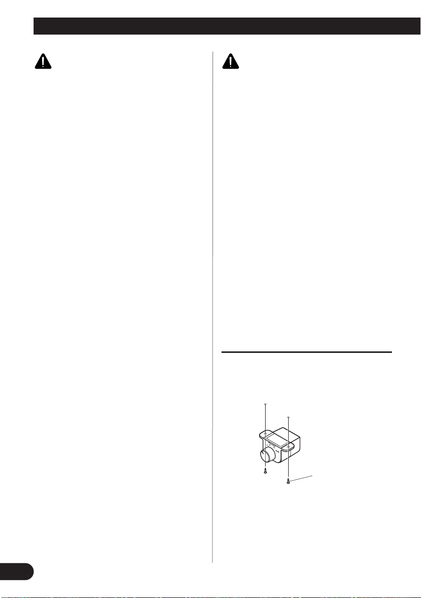
Attaching the Bass boost remote
control
Attach with tapping screws (3 mm × 10 mm) at an
easily accessible location such as under the dashboard.
15
Tapping screw
(3 mm × 10 mm)
Page 17
Example of installation on the floor
mat or on the chassis
1. Place the amplifier where it is to be
installed. Insert the supplied tapping screws (4 mm × 18 mm) into
the screw holes. Push on the screws
with a screwdriver so they make
marks where the installation holes
are to be located.
2. Drill 2.5 mm (1/8 in.) diameter holes
at the point marked, and install the
amplifier, either on the carpet or
directly to the chassis.
Tapping screw
(4 mm × 18 mm)
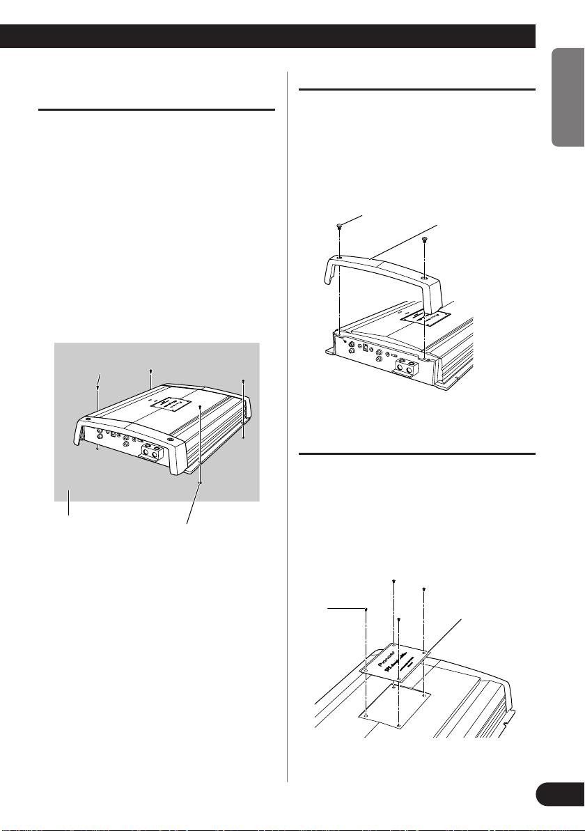
Replacing the terminal cover
1. Align the unit and terminal cover,
and insert the screw.
2. Tighten the screw with a 4 mm
hexagonal wrench.
Screw
Terminal Cover
Changing the Direction of the Badge
ENGLISH
ESPAÑOL DEUTSCH FRANÇAIS ITALIANO
Floor mat or chassis
Drill a 2.5 mm (1/8 in.)
diameter hole
1. To remove the badge, loose screws
by using a 2 mm hexagonal wrench.
2. Change the direction of badge, and
then tighten the screws with a
hexagonal wrench.
Screw
Badge
NEDERLANDS
кмллдав
16
Page 18

Additional information
Troubleshooting
The following indicators light momentarily when the amplifier is turned on. This is not a malfunction.
HEAT Indicator
• This indicator lights up in yellow when the temperature within the amplifier rises. When this happens,
immediately discontinue use of the amplifier and check the location where the amplifier is installed (see the
“WARNING” section on page 2). Contact your dealer if the problem is still not corrected.
PROTECT Indicator
• This indicator either flashes or lights up in red when some type of problem has occurred in the amplifier.
When this happens, immediately discontinue use of the amplifier and check the wiring (see the “WARNING” section on page 2). Contact your dealer if the problem is still not corrected.
17
Page 19

Specifications
Power source ........................................................................................................ 14.4 V DC (10.8 V to 15.1 V allowable)
Grounding system .......................................................................................................................................... Negative type
Current consumption ........................................................................................................ 44 A (at continuous power, 4 Ω)
Average current drawn* .......................................................................................................... 12 A (4 Ω for one channel)
26 A (2 Ω for one channel)
34 A (1 Ω for one channel)
Fuse ........................................................................................................................................................................ 40 A × 4
Dimensions ...................................................................................................................... 381 (W) × 65 (H) × 282 (D) mm
[1 ft. 3 in. (W) × 2-1/2 in. (H) × 1-1/8 in. (D)]
Weight ...................................................................................................... 6.0 kg (13 lbs.) (Leads for wiring not included)
Maximum power output ...................................................... 1 000 W × 1 (4 Ω) / 2 000 W × 1 (2 Ω) / 2 400 W × 1 (1 Ω)
Continuous power (14.4 V) .................................................................. 4 Ω, 20 Hz to 240 Hz, 1.0 % THD, 500 W × 1
2 Ω, 50 Hz, 1.0 % THD, 1 000 W × 1
1 Ω, 50 Hz, 2.0 % THD, 1 200 W × 1
Load impedance ........................................................................................................................ 4 Ω (1 Ω to 8 Ω allowable)
Frequency response .......................................................................................................... 10 Hz to 240 Hz (+0 dB, –3 dB)
S/N ratio ........................................................................................................................................ 80 dB (IHF-A network)
Distortion .................................................................................................................................. 0.3 % (10 W/4 Ω, 100 Hz)
Low pass filter ............................................................................................................ Cut off frequency: 40 Hz to 240 Hz
Cut off slope: –24 dB/oct.
Subsonic filter (HPF) .............................................................................................................................. Frequency: 20 Hz
Slope: –24 dB/oct.
Bass boost .............................................................................................................................. Frequency: 40 Hz to 120 Hz
Level: 0 / 6 / 9 / 12 dB
Gain control .................................................................................................................................... RCA: 400 mV to 6.5 V
Maximum input level / impedance ...................................................................................................... RCA: 6.5 V / 22 kΩ
Power output ........................................................................................ 500 W RMS × 1 channel
(at 4 Ω and 1% THD+N)
1 000 W RMS × 1 channel
(at 50 Hz , 2 Ω and 1% THD+N)
S/N ratio ................................................................................ 54 dBA (reference: 1 W into 4 Ω)
ENGLISH
ESPAÑOL DEUTSCH FRANÇAIS ITALIANO
Note:
• Specifications and the design are subject to possible modification without notice
due to improvements.
*Average current drawn
• The average current drawn is nearly the maximum current drawn by this unit
when an audio signal is input. Use this value when working out total current
drawn by multiple power amplifiers.
NEDERLANDS
кмллдав
18
Page 20

Table des matières
Avant d’utiliser cet appareil
Avant d’utiliser cet appareil .................... 1
Enregistrement du produit ................................ 2
Quelques mots concernant cet appareil ............ 2
PRÉCAUTION .................................................. 2
ATTENTION .................................................... 2
Réglage de l’appareil ................................ 3
Commutateur MODE SELECT ........................ 3
Commande de fréquence de l’accentuation
des graves .................................................. 3
Commande du niveau d’accentuation
des graves .................................................. 3
Couvre-bornes .................................................. 3
Commande de la fréquence de coupure pour
LPF ............................................................ 3
Commande du gain ............................................ 4
Interrupteur BFC (Commande de fréquence
de battement) .............................................. 4
Témoin HEAT .................................................. 4
Témoin PROTECT ............................................ 4
Témoin d’alimentation ...................................... 4
Sélecteur infrasonore ........................................ 4
Réglage correct du gain .................................... 5
Raccordement de l’appareil .................... 6
Schéma de raccordement .................................. 7
Prise de connexion sans soudure ...................... 8
Raccordement des bornes de sortie vers les
haut-parleurs .............................................. 8
Raccordement de la borne d’alimentation ........ 9
Réglage du gain de l’amplificateur associé .... 10
Connexion des câbles des haut-parleurs .......... 10
Installation ................................................ 15
Fixation de la télécommande d’accentuation
des graves.................................................. 15
Exemple d’installation sur le tapis de sol ou
sur le châssis ............................................ 16
Remise en place du couvre-bornes .................. 16
Changement de la direction de l’étiquette
signalétique .............................................. 16
Informations complémentaires ............ 17
Guide de dépannage ........................................17
Caractéristiques techniques ................ 18
Nous vous remercions d’avoir porté votre
choix sur un appareil PIONEER. Il a été
conçu et fabriqué pour vous apporter de
nombreuses années de satisfaction.
En raison des problèmes posés par
l’installation de cet appareil, Pioneer vous
conseille de consulter un professionnel.
Avant d’utiliser l’appareil, prenez
connaissance de ce mode d’emploi et tout
spécialement des AVERTISSEMENTS.
Pour toute question concernant cet
appareil, veuillez vous adresser au
revendeur ou à l’installateur.
Service après-vente pour un
produit Pioneer
Pour toute question, et en particulier pour toute
question relative au service après-vente (y compris
celles qui relèvent de la garantie), veuillez vous
adresser au revendeur ou au distributeur auprès de
qui vous avez acquis ce produit. Dans l’hypothèse
où vous ne pourriez pas être renseigné comme
vous le désirez, consultez l’une des sociétés
mentionnées ci-dessous.
N’expédiez pas le produit à l’une de ces sociétés,
quelle qu’en soit la raison, avant d’y avoir été
expressément invité.
7 Etats-Unis
Pioneer Electronics (USA) Inc.
CUSTOMER SUPPORT DIVISION
P.O. Box 1760
Long Beach, CA 90801-1760
800-421-1404
7 Canada
Pioneer électroniques du Canada, Inc.
Département de service aux consommateurs
300 Allstate Parkway
Markham, Ontario L3R OP2
1-877-283-5901
Pour toute question concernant la garantie,
veuillez consulter le document Garantie Limitée
qui accompagne le produit.
1
Page 21

Enregistrement du produit
Rendez-nous visite sur le site suivant:
1 Enregistrez votre produit. Nous conserverons sur
fichier les détails de votre achat pour vous permettre de vous reporter à ces informations en cas de
déclaration de sinistre à votre assurance pour
perte ou vol.
2 Recevez les mises à jour sur les derniers produits
et les plus récentes technologies.
3 Téléchargez les manuels de l’utilisateur, com-
mandez les catalogues des produits, recherchez
de nouveaux produits, et bien plus.
Quelques mots concernant
cet appareil
Cet appareil est un amplificateur pour
haut-parleur d’extrême grave. Si les deux
canaux, L (gauche) et R (droit), sont
connectés à l’entrée cinch (RCA) de cet
appareil, la sortie est mixée parce que cet
appareil est un amplificateur monaural.
PRÉCAUTION
• Ne remplacez pas le fusible par un fusible de plus
grande valeur ou de plus grand calibre.
L’utilisation d’un fusible inadapté peut entraîner
une surchauffe et de la fumée, et peut provoquer
l’endommagement de l’appareil et des blessures,
y compris des brûlures.
• Utilisez la clé hexagonale fournie pour serrer les
vis lors de la fixation des câbles sur la borne ou
lors du changement de la direction de l’étiquette
signalétique. L’utilisation d’une longue clé
hexagonale en vente dans le commerce peut
entraîner l’application d’un couple de serrage
excessif et endommager les bornes et les câbles.
ATTENTION
• Utilisez le câble de liaison à la batterie et le câble
de masse conseillés; ils sont vendus séparément.
Reliez le câble rouge à la borne positive (+) de la
batterie et le câble de masse à la carrosserie du
véhicule.
• Ne touchez pas l’amplificateur quand vous avez
les mains mouillées, faute de quoi vous risquez
de ressentir une secousse électrique. Pareillement,
ne touchez pas l’amplificateur s’il est mouillé.
• Pour votre sécurité et celles des autres usagers de
la route, maintenez le niveau d’écoute à une
valeur telle que les bruits de la circulation
demeurent nettement perceptibles.
• Si le fusible monté sur le câble de liaison à la
batterie, câble qui est vendu séparément, a grillé
ou bien s’il en est ainsi de celui de l’amplificateur, vérifiez soigneusement toutes les connexions d’alimentation. Recherchez la cause de
l’anomalie puis corrigez-la; enfin, remplacez le
fusible grillé par un fusible de même taille et de
même calibre.
• Pour éviter d’endommager l’amplificateur et du
haut-parleur d’extrême grave, le circuit de protection coupe l’alimentation de l’amplificateur (les
sons ne sont plus émis) dès que survient une situation anormale. Dans ce cas, mettez l’ensemble
des appareils hors tension et contrôlez les liaisons
entre l’amplificateur et du haut-parleur d’extrême
grave. Le cas échéant, recherchez la cause de
l’anomalie et corrigez-la.
• Consultez le revendeur si vous n’êtes pas en
mesure de résoudre le problème qui se pose à
vous.
• Pour éviter toute secousse électrique et tout
risque de court-circuit au cours des opérations de
raccordement et d’installation, n’oubliez pas de
débrancher le câble relié au pôle négatif de la
batterie (–) avant d’effectuer quelque opération
que ce soit.
• Avant d’effectuer un perçage requis par
l’installation de l’amplificateur, assurez-vous que
vous pouvez le faire sans danger pour les câbles,
canalisations, flexibles, etc., qui sont placés
derrière le panneau que vous devez percer.
• NE LAISSEZ PAS l’amplificateur entrer en contact avec des liquides à cause, par exemple, de
l’emplacement où il a été placé. Cela pourrait
entraîner une secousse électrique. De plus, le contact avec un liquide pourrait endommager l’amplificateur et les enceintes, produire de la fumée
ou surchauffer l’appareil. Enfin, la surface de
l’amplificateur et des enceintes connectées peut
devenir chaude au toucher et entraîner de légères
brûlures.
ENGLISH
FRANÇAIS DEUTSCH FRANÇAIS ITALIANO
NEDERLANDS
кмллдав
2
Page 22

Réglage de l’appareil
Commutateur MODE SELECT
Vous pouvez sélectionner le mode de synchronisation de l’amplificateur, à savoir MASTER, SYNC
et SYNC INV. Réglez le commutateur MODE
SELECT sur la position MASTER si vous utilisez
uniquement un amplificateur. Si vous utilisez deux
amplificateur ou plus en combinaison et connecteur de façon synchrone, réglez le premier
amplificateur sur MASTER, et les amplificateurs
restants sur SYNC ou SYNC INV en fonction de
la façon dont ils sont connectés. Réglez le commutateur d’un amplificateur sur SYNC INV uniquement quand les amplificateurs sont connectés de
façon synchrone avec un montage en pont ex. Pour
régler le commutateur sur SYNC ou SYNC INV,
retirez la vis et la butée. Retirez la vis et la butée
après avoir vérifié que les connexions sont correctes. Pour en savoir plus sur le commutateur
MODE SELECT, reportez-vous à la section
“Connexion des câbles des haut-parleurs”.
Commande de fréquence de l’accentuation des graves
Cette commande permet de choisir la
fréquence, entre 40 Hz et 120 Hz, autour
de laquelle doit s’effectuer l’accentuation.
Couvre-bornes
Avant de mettre l’appareil en
place, dévissez les vis avec un
tournevis à pointe hexagonale de
4 mm et retirez le couvre-bornes.
Commande du niveau d’accentuation des graves
Vous pouvez choisir un niveau
d’accentuation de 0, 6, 9 ou 12 dB.
Pour connaître la manière de relier le boîtier
de télécommande d’accentuation des graves
à l’amplificateur, reportez-vous à la section
“Schéma de raccordement”.
3
Commande de la fréquence
de coupure pour LPF
La fréquence de coupure peut être
choisie entre 40 Hz et 240 Hz.
Page 23

Commande du gain
Si le niveau d’écoute est faible même lorsque la commande de l’autoradio est sur la position
correspondant au maximum, tournez la commande de gain dans le sens des aiguilles d’une
montre. Inversement, si vous constatez de la distorsion lorsque vous augmentez le niveau de
sortie de l’autoradio, tournez cette commande dans le sens contraire des aiguilles d’une montre.
• Choisissez la position NORMAL si l’autoradio stéréo est équipé de prises Cinch (RCA) (niveau de sortie
standard à 500 mV). Si cet appareil est utilisé conjointement avec un autoradio stéréo Pioneer pourvu de
prises Cinch (RCA) sur lesquelles peuvent se trouver une tension de sortie de 4 V ou plus, réglez le niveau
en fonction du niveau de sortie de l’autoradio.
• Pour la commande de gain de l’amplificateur associé, reportez-vous à la section “Réglage du gain de
l’amplificateur associé”.
Interrupteur BFC (Commande de fréquence de battement)
Si vous entendez un battement pendant l’écoute d’une transmission AM avec
votre autoradio, changer la position de l’interrupteur BFC en utilisant un petit
tournevis standard.
Témoin HEAT (Jaune)
Ce témoin indique un problème avec l’amplificateur. Reportez-vous à la
section “Guide de dépannage” à la page 17 pour en savoir plus.
ENGLISH
FRANÇAIS DEUTSCH FRANÇAIS ITALIANO
Témoin PROTECT (Rouge)
Ce témoin indique un problème avec l’amplificateur. Reportez-vous à la
section “Guide de dépannage” à la page 17 pour en savoir plus.
Témoin d’alimentation (Bleu)
Ce témoin s’éclaire lorsque l’amplificateur est sous tension.
Sélecteur infrasonore
Le filtre infrasonore coupe les fréquences
inférieures à 20 Hz afin de supprimer les
vibrations indésirables et de réduire les
pertes de puissance.
NEDERLANDS
кмллдав
4
Page 24

Réglage de l’appareil
r
Niveau de
préamplification: 2 V
(Standard: 500 mV)
Niveau de
préamplification: 4 V
Niveau de
préamplification: 6,5 V
Réglage correct du gain
• Cet appareil est muni d’une fonction de protection
qui protège l’appareil et les enceintes de tout
mauvais fonctionnement dû à une utilisation
incorrecte ou à une connexion incorrecte.
• Quand le son est sorti à un niveau de volume
élevé, etc. cette fonction coupe la sortie du son en
quelques secondes. Ce n’est pas un mauvais fonctionnement. Si vous baissez le niveau de volume
de l’appareil principal, la sortie du son est
rétablie.
• Si la sortie du son est coupée, c’est peut-être
parce que la commande de gain de cet appareil est
réglée incorrectement. Pour assurer une sortie
continue du son même quand le niveau de volume
de l’appareil principal est augmenté, réglez la
commande du gain de l’amplificateur sur une
position correcte en fonction du niveau de sortie
maximum préamplifié de l’appareil principal.
Commande du gain de cet appareil
Il n’est pas nécessaire de diminuer le volume
de l’appareil principal et quand la sortie est
trop forte.
Relation entre le gain de l’amplificateur
et la puissance de sortie de l’appareil
principal
Puissance
Gain normal
Augmentation du volume
de l’appareil principal
Gain de l’amplificateur
(normal)
•
Si vous augmentez le gain de l’amplificateur à un
Puissance égale
niveau incorrect, seule la distorsion est augmentée
et la puissance n’augmente que légèrement.
Puissance
Gain maximum
Augmentation du volume
de l’appareil principal
Gain de l’amplificateu
(maximum)
Forme de signal quand la puissance de
sortie est élevée par la commande gain de
l’amplificateur
Gain normal
Puissance égale
Gain maximum
5
Forme de
signal
Gain de l’amplificateur
(normal)
Forme de
signal
Gain de l’amplificateur
(maximum)
• Quand la puissance de sortie est élevée, la forme
de signal est déformée et si vous augmentez le
gain de l’amplificateur la puissance n’augmente
que légèrement.
• Si vous diminuez le volume de l’appareil principal et réglez la commande de gain de l’amplificateur sur la position correcte mais que le son continue à être coupé de temps à autre, contactez le
centre de service autorisé PIONEER le plus
proche.
Page 25

Raccordement de l’appareil
PRÉCAUTION
• Pour éviter tout risque de court-circuit ou
d’endommager cet appareil, débranchez le câble
relié à la borne négative (–) de la batterie, au
niveau de cette borne.
• Fixez les câbles au moyen de colliers ou du ruban
adhésif. Lorsque l’isolant du câble peut être
endommagé par une pièce métallique, assurez sa
protection en le gainant de ruban adhésif.
• Faites cheminer les câbles en évitant les zones
chaudes telles que les bouches du chauffage. La
chaleur peut endommager l’isolant et il peut en
résulter un court-circuit si l’âme du câble vient en
contact avec la carrosserie.
• L’amplificateur augmente la charge sur la batterie
et le système de charge. Assurez-vous que le l’alternateur et la batterie du véhicule ont une capacité suffisante pour cet amplificateur. L’installation
d’une batterie puissante, la connexion parallèle
d’une batterie secondaire ou d’un condensateur de
stockage d’énergie est recommandée.
PRÉCAUTION
Pour éviter toute anomalie ou blessure
• Ne reliez pas à la masse le câble (–) d’un
haut-parleur; ne reliez pas ensemble plusieurs
câbles négatifs de haut-parleurs.
• Cet appareil est conçu pour les véhicules
alimentés par une batterie 12 V dont le pôle
négatif est à la masse. Avant d’installer cet
appareil, contrôlez la tension de la batterie.
• Si vous conservez l’autoradio en fonctionnement
alors que le moteur est arrêté ou tourne au ralenti,
la batterie peut être déchargée au bout d’un
certain temps. Pour éviter cela, mettez l’autoradio
hors tension.
• Si le câble de commande à distance de l’amplificateur est relié à la borne d’alimentation par l’intermédiaire du contacteur d’allumage (12 V CC),
l’amplificateur sera sous tension dès que vous
mettrez le contact, et cela quelle que soit la situation de l’autoradio. En conséquence, la batterie
peut être rapidement déchargée si le moteur ne
tourne pas, ou tourne au ralenti.
• NE RACCORDEZ PAS un haut-parleur d’extrêmes graves dont l’impédance serait inférieure à
celle prescrite dans la section “Connexion des
câbles des haut-parleurs”. Il pourrait en résulter
un endommagement de l’amplificateur, voire de
la production de fumée accompagnée de surchauffe. La surface de l’amplificateur pourrait
s’échauffer au point de causer des brûlure légères.
• Assurez-vous que les câbles ne gênent en rien la
manoeuvre des organes mobiles tels que rails de
siège mais aussi levier de frein de stationnement,
pédale de frein, etc.
• Veillez à ce qu’aucun câble ne soit en courtcircuit, faute de quoi le circuit de protection
pourrait être dans l’incapacité de remplir son
office.
• N’alimentez pas un appareil par un piquage sur le
câble qui alimente un autre appareil. Ce câble n’a
peut-être pas la section suffisante pour supporter
sans danger l’intensité consommée par les deux
appareils.
• Ne remplacez pas le fusible par un fusible de plus
grande valeur ou de plus grand calibre.
L’utilisation d’un fusible inadapté peut entraîner
une surchauffe et de la fumée, et peut provoquer
l’endommagement de l’appareil et des blessures,
y compris des brûlures.
• Reliez l’un de ces trois caissons de graves à
l’amplificateur; 1: un caisson de graves ayant une
puissance admissible de 500 W ou mieux et une
impédance de 4 Ω, 2: un caisson de graves ayant
une puissance admissible de 1 000 W ou mieux et
une impédance de 2 Ω ou 3: un caisson de graves
ayant une puissance admissible de 1 200 W ou
mieux et une impédance de 1 Ω. Si l’entrée
nominale et l’impédance sont au-dessus de ces
plages, le haut-parleur d’extrême grave risque de
prendre feu, d’émettre de la fumée ou d’être
endommagé.
• Installez le câble de liaison à la batterie, vendu
séparément, et faites-le cheminer aussi loin que
possible des câbles de liaison aux haut-parleurs.
Installez le câble de liaison à la batterie, vendu
séparément, le câble de masse, les câbles de
liaison aux haut-parleurs et l’amplificateur aussi
loin que possible de l’antenne, du câble d’antenne
et du syntoniseur.
• Les câbles de cet appareil et ceux d’autres
appareils peuvent fort bien ne pas être de la même
couleur bien que remplissant la même fonction.
Pour relier cet appareil à un autre appareil, utilisez
le manuel de chacun et effectuez les
raccordements en ne tenant compte que de la
fonction de chaque câble.
ENGLISH
FRANÇAIS DEUTSCH FRANÇAIS ITALIANO
NEDERLANDS
кмллдав
6
Page 26

Raccordement de l’appareil
Schéma de raccordement
•
Dans le cas de la connexion de la sortie extérieure d’un autoradio stéréo à une entrée Cinch (RCA), utilisez la prise utilisée pour une sortie à gamme étendue, car le canal PDF de l’amplificateur ne peut pas être mis hors service. Si cette
prise ne peut pas être utilisée, connectez la prise de sortie du haut-parleur d’extrêmes graves à l’entrée Cinch (RCA).
Câble, borne de masse
(vendu séparément)
Le câble de masse doit avoir la même
section que le câble de batterie.
La longueur maximale du câble
entre le fusible et
la borne positive
(+) de la batterie,
est de 45 cm.
Passe-câble caoutchouté
Prise pour la télécommande d’accentuation des graves
Reliez cette prise et le boîtier de télécommande d’accentuation des graves au moyen d’un câble de télécommande.
Prise SYNC OUTPUT / SYNC INPUT
Pour connaître la manière de raccorder la prise
SYNC OUTPUT / SYNC INPUT, reportez-vous à la
section “Connexion des câbles des haut-parleurs”.
Télécommande d’accentuation
des graves
Borne
positive
(+)
Batterie
Fusible (200 A)
Chaque amplificateur doit être
SÉPARÉMENT protégé par un
fusible de 200 A.
6 m
Borne
négative
(–)
Reliez ce câble à la carrosserie du
véhicule.
Câble de batterie (vendu séparément)
Pour en connaître la section, reportezvous à la section “Raccordement de la
borne d’alimentation”. Le câble de
batterie, le câble de masse et le câble
de mise à la masse directe (en option),
doivent avoir la même section.
Après avoir effectué tous les autres
raccordements de l’amplificateur,
reliez ce câble à la borne positive (+)
de la batterie.
Câble de liaison munis de prises
Cinch (RCA) (vendus séparément).
Prises Cinch
(RCA) de sortie
de l’autoradio
Sortie extérieure
Prises d’entrée Cinch (RCA)
Câble de télécommande
d’accentuation des graves
Fusible (40 A)
7
Bornier de sortie pour
Autre face
Câble de commande à distance d’alimentation
(vendu séparément)
Reliez la fiche mâle de ce câble à la borne de commande à distance de l’autoradio
(SYSTEM REMOTE CONTROL). La fiche femelle doit être reliée à la prise de
commande de l’antenne motorisée. Si l’autoradio ne possède par de prise pour
commande à distance de la mise sous tension, reliez la fiche mâle à une borne
d’alimentation en passant par le contacteur d’allumage.
haut-parleur
Reportez-vous à la section
“Connexion des câbles
des haut-parleurs”.
Fusible (40 A)
Page 27

Prise de connexion sans soudure
• Comme le câble devient lâche avec le temps, il
doit être vérifié périodiquement et resserré si
nécessaire.
• Ne soudez ni ne tordez les extrémités des âmes
torsadées.
• Serrez en vous assurant de ne pas coincer la gaine
isolante du câble.
• Utilisez la clé hexagonale fournie pour serrer et
desserrer la vis de la prise de l’amplificateur.
Serrez le câble solidement avec la vis de la prise.
Cependant, faites attention de ne pas serrer excessivement en contrôlant l’état du câble pendant le
serrage car un serrage excessif de la vis de la prise
du système de commande à distance peut endommager le câble.
Raccordement des bornes de
sortie vers les haut-parleurs
Taille des câbles de haut-parleur
Longueur moins de moins de moins de
du câble
Section
du câble
5,2 m 8,2 m 13,4 m
8 AWG 6 AWG 4 AWG
ENGLISH
1. Dénudez l’extrémité des câbles de
haut-parleurs sur environ 18 mm à
20 mm en utilisant des pinces ou un
cutter.
FRANÇAIS DEUTSCH FRANÇAIS ITALIANO
18 mm à 20 mm
2. Reliez les câbles de liaisons aux hautparleurs aux bornes de sortie vers les
haut-parleurs.
• Serrez soigneusement les cosses au moyen des
vis.
Vis de borne
Câble de liaison à
un haut-parleur
Borne de
sortie
vers un
haut-parleur
3. Engagez les colliers de câble dans les
fentes et liez les câbles au moyen des
colliers.
• Le collier doit entourer les câbles au niveau de
leur isolant et non pas à hauteur de la partie
dénudée.
• Coupez les parties en excès des colliers pour
câble.
NEDERLANDS
Collier pour câble
кмллдав
8
Page 28

Raccordement de l’appareil
Raccordement de la borne
d’alimentation
• Utilisez le câble de liaison à la batterie et le câble
de masse conseillés; ils sont vendus séparément.
Reliez le câble rouge à la borne positive (+) de la
batterie et le câble de masse à la carrosserie du
véhicule.
• La section conseillée des câbles est la suivante
(suivant AWG, American Wire Gauge). Le câble
de batterie, le câble de masse et le câble de mise à
la masse directe doivent avoir la même section.
• Utilisez un câble de 10 AWG à 20 AWG pour le
câble de commande à distance d’alimentation.
Section de câble de la batterie et câble de masse
Longueur du câble moins de 3,6 m moins de 6,4 m
Section du câble 6 AWG 4 AWG
1. Faites passer le câble de liaison à la
batterie du compartiment moteur
vers l’intérieur du véhicule.
• Après avoir effectué tous les autres
raccordements de l’amplificateur, reliez la
borne d’alimentation de l’amplificateur à la
borne positive (+) de la batterie.
La longueur maximale du câble entre
le fusible et la borne positive (+) de la
batterie, est de 45 cm.
Borne
positive
(+)
Compartiment
moteur
Fusible 200 A
Chaque amplificateur doit être
SÉPARÉMENT
protégé par un
fusible de 200 A.
Engagez le passe-câble en
caoutchouc dans le perçage
pour assurer la protection
du câble.
Intérieur du
véhicule
Percez un
trou de 14
mm dans le
tablier.
2. Dénudez l’extrémité des câbles en
utilisant des pinces ou un cutter.
• Câble de la batterie, câble de masse:
18 mm à 20 mm
•
Câble de commande à distance d’alimentation:
14 mm à 16 mm
3. Reliez les câbles aux bornes.
• Serrez soigneusement les câbles au moyen des vis.
Borne de commande à
distance d’alimentation
Borne d’alimentation
Câble de la
batterie
Câble de commande à distance
d’alimentation
Câble de masse
Vis de
borne
Borne de
masse
(GND)
ATTENTION
Faute de serrer soigneusement le câble de batterie
sur la borne au moyen d’une vis de borne, une élé-
vation importante de température de la borne peut se
produire et provoquer dommages et blessures, y
compris brûlures légères.
4. Engagez les colliers de câble dans
les fentes et liez les câbles au moyen
des colliers.
• Le collier doit entourer les câbles au niveau
de leur isolant et non pas à hauteur de la partie dénudée.
• Coupez les parties en excès des colliers pour câble.
9
Collier pour câble
Page 29

Réglage du gain de l’amplificateur associé
Après avoir relié les câbles des haut-parleurs, réglez la commande de gain de l’amplificateur associé. Les
amplificateurs associés suivent les réglages de l’amplificateur maître.
ENGLISH
Réglage sommaire du gain
Réglez la commande de gain de chaque amplificateur sur la position NORMAL. Ce réglage est suffisant pour
obtenir une sortie équilibrée dans la majeure partie des cas.
Réglage fin du gain
Réglez la commande de gain de chaque amplificateur associé, en commençant par l’amplificateur maître.
1. À l’aide de ce système, générez une sinusoïde de basse amplitude.
2. Au moyen d’un voltmètre, mesurez l’amplitude de la tension de sortie de l’amplificateur maître.
3. Au moyen d’un voltmètre, mesurez l’amplitude de la tension de sortie de l’amplificateur associé.
4. Au moyen de la commande de gain de l’amplificateur associé, réglez la tension de sortie de l’amplificateur
associé au même niveau que celle de l’amplificateur maître.
5. Répétez les mêmes opérations, dans l’ordre, pour tous les amplificateurs associés.
Connexion des câbles des haut-parleurs
Connectez les câbles de haut-parleurs et réglez le commutateur MODE SELECT correctement en fonction de
la configuration et des illustrations ci-dessous et de la page suivante.
• Lors de la connexion de deux amplificateurs ou plus en combinaison de façon synchrone, utilisez uniquement ces amplificateurs. Ne les mélangez pas avec d’autres amplificateurs.
• Lors de la connexion de deux amplificateurs ou plus en combinaison de façon synchrone, réglez la commande de gain, le sélecteur infrasonore, la commande de la fréquence de coupure pour LPF et la commande
d’accentuation des graves sur l’amplificateur dont le commutateur MODE SELECT a été réglé sur
MASTER. Ces réglages, à l’exception de la commande du gain, sont inactifs sur un amplificateur qui a été
réglé sur SYNC ou SYNC INV. Pour les détails concernant les opérations de commande du gain, reportezvous à “Réglage du gain de l’amplificateur associé”.
FRANÇAIS DEUTSCH FRANÇAIS ITALIANO
NEDERLANDS
кмллдав
10
Page 30

Raccordement de l’appareil
PRÉCAUTION
Diagramme A - Correct Diagramme B - Incorrect
Enceinte
de 4 Ω
Branchement en pont de 2 Ω Branchement en pont de 1 Ω
NE PAS installer ou utiliser cet amplificateur en câblant des haut-parleurs de 2 Ω (ou moins) en parallèle pour
obtenir un branchement en pont de 1 Ω (ou moins) (schéma B).
Ce type de branchement incorrect peut provoquer des détériorations, de la fumée et une surchauffe de l’amplificateur. Le boîtier de l’amplificateur peut aussi devenir chaud et être à l’origine de brûlures légères.
Pour installer ou utiliser correctement un branchement en pont et obtenir une charge de 2 Ω, câbler deux hautparleurs de 4 Ω en parallèle avec Gauche + et Droite – (schéma A) ou utiliser un seul haut-parleur de 2 Ω.
De plus, reportez-vous au manuel d’instructions des haut-parleurs pour en savoir plus sur la procédure de connexion correcte.
Amplificateur unique
Le commutateur MODE SELECT
doit être sur la position MASTER.
Amplificateur Amplificateur
Enceinte
de 4 Ω
Amplificateur Amplificateur
Connectez à un autoradio.
Pour les détails, référez-vous à la section “Schéma de
raccordement”.
Enceinte
de 2
Enceinte
Ω
de 2 Ω
• Utilisez des haut-parleurs avec une impédance comprise entre 1 Ω et 8 Ω.
11
1 Ω à 8 Ω
1 200 W
(1 Ω)
Page 31

Deux amplificateurs (connexion en pont ex.)
Connectez à un autoradio.
Le commutateur MODE
SELECT doit être sur la
position MASTER.
MODE SELECT doit
être sur la position
SYNC INV position.
Avant de le placer sur
cette position, retirez
la vis et la butée.
• Utilisez uniquement des haut-parleurs avec une impédance comprise entre 2 Ω et 16 Ω. De plus en cas de
connexion de plusieurs haut-parleurs avec un pont, vérifiez que l’impédance synthétique est d’au moins 2 Ω.
SYNC OUTPUT
SYNC
INPUT
Connexion de cable munis
de prises Cinch (RCA)
(vendus séparément).
Connexion des câbles
des haut-parleurs
(vendus séparément).
Pour les détails, référez-vous à la section “Schéma de
raccordement”.
2 Ω à 16 Ω
2 400 W
(2 Ω)
Deux amplificateurs
Le commutateur MODE SELECT
doit être sur la position MASTER.
SYNC OUTPUT
Connectez à un autoradio.
Pour les détails, référez-vous à la section “Schéma de
raccordement”.
ENGLISH
FRANÇAIS DEUTSCH FRANÇAIS ITALIANO
Connexion de cable munis
Le commutateur MODE
SELECT doit être sur la
position SYNC. Avant de
le placer sur cette position, retirez la vis et la
butée.
• Utilisez des haut-parleurs avec une impédance comprise
entre 1 Ω et 8 Ω.
SYNC
INPUT
de prises Cinch (RCA) (vendus séparément).
1 Ω à 8 Ω
1 200 W
(1 Ω)
1 Ω à 8 Ω
1 200 W
(1 Ω)
NEDERLANDS
кмллдав
12
Page 32

Raccordement de l’appareil
Quatre amplificateurs (connexion en pont ex.)
Connectez à un autoradio.
Le commutateur MODE
SELECT doit être sur la
position MASTER.
SYNC
OUTPUT
Pour les détails, référez-vous à la
section “Schéma de raccordement”.
MODE SELECT doit
être sur la position
SYNC INV position.
Avant de le placer sur
cette position, retirez
la vis et la butée.
MODE SELECT doit
être sur la position
SYNC INV position.
Avant de le placer sur
cette position, retirez
la vis et la butée.
MODE SELECT doit
être sur la position
SYNC INV position.
Avant de le placer sur
cette position, retirez
la vis et la butée.
SYNC
OUTPUT
SYNC
INPUT
SYNC
OUTPUT
SYNC
INPUT
Connexion de cable munis
de prises Cinch (RCA)
(vendus séparément).
Connexion de cable munis
de prises Cinch (RCA)
(vendus séparément).
Connexion de cable munis
de prises Cinch (RCA)
(vendus séparément).
Connexion des câbles
des haut-parleurs
(vendus séparément).
2 Ω à
16 Ω
4 800 W
(2 Ω
DVC)
Connexion des câbles
des haut-parleurs
(vendus séparément).
SYNC
INPUT
•
Utilisez uniquement des haut-parleurs avec une impédance comprise entre 2 Ωet 16 Ω. De plus en cas de
connexion de plusieurs haut-parleurs avec un pont, vérifiez que l’impédance synthétique est d’au moins 2 Ω.
13
Page 33

Quatre amplificateurs
Le commutateur MODE
SELECT doit être sur la
position MASTER.
SYNC OUTPUT
ENGLISH
Connectez à un autoradio.
Pour les détails, référez-vous à la section
“Schéma de raccordement”.
FRANÇAIS DEUTSCH FRANÇAIS ITALIANO
Le commutateur MODE
SELECT doit être sur la
position SYNC. Avant
de le placer sur cette
position, retirez la vis et
la butée.
Le commutateur
MODE SELECT doit
être sur la position
SYNC. Avant de le
placer sur cette position, retirez la vis et la
butée.
Le commutateur MODE
SELECT doit être sur la
position SYNC. Avant de le
placer sur cette position,
retirez la vis et la butée.
SYNC
OUTPUT
SYNC
OUTPUT
SYNC
INPUT
SYNC
INPUT
Connexion de cable munis
de prises Cinch (RCA)
(vendus séparément).
Connexion de cable munis
de prises Cinch (RCA)
(vendus séparément).
Connexion de cable munis
de prises Cinch (RCA)
(vendus séparément).
1 Ω à 8 Ω
1 200 W
(1 Ω)
1 Ω à 8 Ω
1 200 W
(1 Ω)
1 Ω à 8 Ω
1 200 W
(1 Ω)
NEDERLANDS
SYNC INPUT
• Utilisez des haut-parleurs avec une impédance comprise entre 1 Ω et 8 Ω.
1 Ω à 8 Ω
1 200 W
(1 Ω)
кмллдав
14
Page 34

Installation
PRÉCAUTION
• N’installez pas l’appareil:
—dans un endroit où il pourrait blesser un occu-
pant du véhicule en cas d’arrêt brusque;
—dans un endroit où il pourrait gêner le con-
ducteur, par exemple devant son siège.
• Veillez à ce que les câbles ne puissent pas être
pincés et endommagés par les sièges, ce qui peut
conduire à un court-circuit.
• Avant d’effectuer un perçage requis par l’installa-
tion de l’amplificateur, assurez-vous que vous
pouvez le faire sans danger pour les câbles, canalisations, flexibles, etc., qui sont placés derrière le
panneau que vous devez percer.
• Posez les vis autotaraudeuses de manière que leur
extrémité ne puisse pas endommager les câbles. Il
est important que l’isolant d’un câble ne soit pas
endommagé par le frottement sur une pièce, ce
qui pourrait ultérieurement entraîner un court-circuit.
• NE LAISSEZ PAS l’amplificateur entrer en con-
tact avec des liquides à cause, par exemple, de
l’emplacement où il a été placé. Cela pourrait
entraîner une secousse électrique. De plus, le contact avec un liquide pourrait endommager l’amplificateur et les enceintes, produire de la fumée
ou surchauffer l’appareil. Enfin, la surface de
l’amplificateur et des enceintes connectées peut
devenir chaude au toucher et entraîner de légères
brûlures.
• Pour effectuer convenablement l’installation,
utilisez les pièces fournies et procédez comme il
est indiqué. L’utilisation de pièces autres que
celles fournies peut endommager l’amplificateur.
• Ne remplacez pas le fusible par un fusible de plus
grande valeur ou de plus grand calibre.
L’utilisation d’un fusible inadapté peut entraîner
une surchauffe et de la fumée, et peut provoquer
l’endommagement de l’appareil et des blessures,
y compris des brûlures.
PRÉCAUTION
Pour éviter toute anomalie de
fonctionnement ou blessure
• Pour que la chaleur puisse se dissiper sans mal,
respectez ce qui suit:
—veillez à ce qu’un espace dégagé existe au-
dessus de l’amplificateur;
—ne recouvrez pas l’amplificateur d’un tapis ou
d’une moquette.
• NE LAISSEZ PAS l’amplificateur entrer en contact avec des liquides à cause, par exemple, de
l’emplacement où il a été placé. Cela pourrait
entraîner une secousse électrique.
De plus, le contact avec un liquide pourrait
endommager l’amplificateur et les enceintes, produire de la fumée ou surchauffer l’appareil. Enfin,
la surface de l’amplificateur et des enceintes connectées peut devenir chaude au toucher et entraîn-
er de légères brûlures.
• N’installez pas l’amplificateur sur une surface
instable telle que le tapis amovible cachant la roue
de secours.
• Le meilleur emplacement d’installation dépend du
véhicule, mais, quoi qu’il en soit, doit être rigide
et solide.
• Effectuez tout d’abord des raccordements temporaires pour vous assurer que l’amplificateur et les
autres appareils fonctionnent correctement.
• Choisissez un emplacement qui permette le retrait
sans peine de la roue de secours, du cric et de la
boîte à outils.
Fixation de la télécommande d’ac-
centuation des graves
Fixez-la avec les vis autotaraudeuses (3 mm × 10
mm) dans un endroit facile d’accès tel que sous le
tableau de bord.
15
Vis autotaraudeuse
(3 mm × 10 mm)
Page 35

Exemple d’installation sur le tapis
de sol ou sur le châssis
1. Posez l’amplificateur à l’emplacement choisi. Introduisez les vis autotaraudeuses fournies (4 mm × 18 mm)
dans les perçages. Appuyez fermement sur les vis au moyen d’un
tournevis pour marquer les points
de perçage.
2. Percer des trous de 2,5 mm de
diamètre aux emplacements marqués puis fixez l’amplificateur soit à
travers le tapis, soit directement sur
le châssis.
Vis autotaraudeuse
(4 mm × 18 mm)
Remise en place du couvre-bornes
1. Alignez l’appareil et le
couvre-bornes et insérez les vis.
2. Serrez les vis avec un tournevis à
pointe hexagonale de 4 mm.
Vis
Couvre-bornes
Changement de la direction de
l’étiquette signalétique
ENGLISH
FRANÇAIS DEUTSCH FRANÇAIS ITALIANO
Tapis ou châssis
Percer un trou de 2,5 mm
de diamètre
1. Pour retirer l’étiquette signalétique,
desserrez les vis en utilisant une clé
hexagonale de 2 mm.
2. Changez la direction de l’étiquette
signalétique, puis serrez les vis avec
la clé hexagonale.
Vis
Étiquette
signalétique
NEDERLANDS
кмллдав
16
Page 36

Informations complémentaires
Guide de dépannage
Les témoins suivants s’allument momentanément quand l’amplificateur est mis sous tension. Ce n’est pas un
mauvais fonctionnement.
Témoin HEAT
• Ce témoin s’allume en jaune quand la température interne de l’amplificateur augmente. Si cela se produit,
arrêtez immédiatement d’utiliser l’amplificateur et vérifiez l’emplacement d’installation (reportez-vous à la
section “ATTENTION” de la page 2). Contactez votre revendeur si le problème ne peut pas être corrigé.
Témoin PROTECT
• Ce témoin clignote ou s’allume en rouge quand un certain type de problème se produit dans l’amplificateur.
Si cela se produit, arrêtez immédiatement d’utiliser l’amplificateur et vérifiez les connexions (reportez-vous
à la section “ATTENTION” de la page 2). Contactez votre revendeur si le problème ne peut pas être corrigé.
17
Page 37

Caractéristiques techniques
Alimentation .............................................................................................................. 14,4 V CC (10,8 V à 15,1 V permis)
Mise à la masse ............................................................................................................................ Pôle négatif de la batterie
Consommation de courant .......................................................................................... 44 A (à la puissance continue, 4 Ω)
Consommation moyenne de courant* ........................................................................................ 12 A (4 Ω pour une voie)
26 A (2 Ω pour une voie)
34 A (1 Ω pour une voie)
Fusible .................................................................................................................................................................... 40 A × 4
Dimensions ........................................................................................................................ 381 (L) × 65 (H) × 282 (P) mm
Poids ................................................................................................................................................ 6,0 kg (sans les câbles)
Puissance maximale de sortie .............................................. 1 000 W × 1 (4 Ω) / 2 000 W × 1 (2 Ω) / 2 400 W × 1 (1 Ω)
Puissance continue (14,4 V).................................................................... 4 Ω, 20 Hz à 240 Hz, 1,0 % DHT, 500 W × 1
2 Ω, 50 Hz, 1,0 % DHT, 1 000 W × 1
1 Ω, 50 Hz, 2,0 % DHT, 1 200 W × 1
Impédance de charge ...................................................................................................................... 4 Ω (1 Ω à 8 Ω permis)
Réponse en fréquence ........................................................................................................ 10 Hz à 240 Hz (+0 dB, –3 dB)
Rapport signal/bruit .......................................................................................................................... 80 dB (réseau IHF-A)
Distorsion ................................................................................................................................ 0,3 % (10 W / 4 Ω, 100 Hz)
Filtre passe-bas ...................................................................................................... Fréquence de coupure: 40 Hz à 240 Hz
Pente: –24 dB/oct.
Filtre infrasonore (HPF) .......................................................................................................................... Fréquence: 20 Hz
Pente: –24 dB/oct.
Accentuation des graves .......................................................................................................... Fréquence: 40 Hz à 120 Hz
Niveau: 0 / 6 / 9 / 12 dB
Commande de gain .......................................................................................................................... RCA: 400 mV à 6,5 V
Niveau maximale / impédance d’entrée .............................................................................................. RCA: 6,5 V / 22 kΩ
Puissance de sortie ........................................................................................ 500 W eff. × 1 voie
(pour 4 Ω et 1% DHT+N)
1 000 W eff. × 1 voie
(pour 50 Hz , 2 Ω et 1% DHT+N)
Rapport signal/bruit ................................................................ 54 dBA (référence: 1 W sur 4 Ω)
ENGLISH
FRANÇAIS DEUTSCH FRANÇAIS ITALIANO
Remarque:
• Les caractéristiques et la présentation peuvent être modifiées sans avis préalable à
fin d’amélioration.
* Consommation moyenne de courant
• Le courant moyen est proche du courant maximal lorsqu’un signal audio est
appliqué à l’entrée de l’amplificateur. Utilisez cette valeur lorsque vous désirez
calculer le courant total consommé par plusieurs amplificateurs de puissance.
NEDERLANDS
кмллдав
18
Page 38

Contenido Antes de usar este producto
Antes de usar este producto .................... 1
Registro del producto ........................................2
Sobre este producto .......................................... 2
PRECAUCION ................................................ 2
ADVERTENCIA .............................................. 2
Ajuste de esta unidad .............................. 3
Interruptor MODE SELECT ............................ 3
Control de la frecuencia de refuerzo de
graves ........................................................ 3
Control de nivel de refuerzo de los graves ........ 3
Cubierta de terminales ...................................... 3
Control de frecuencia de corte para LPF .......... 3
Control de ganancia .......................................... 4
Interruptor BFC (Control de la frecuencia de
batido) ........................................................ 4
Indicador HEAT ................................................ 4
Indicador PROTECT ........................................ 4
Indicador de alimentación ................................ 4
Interruptor selector subsónico .......................... 4
Configuración apropiada de la ganancia .......... 5
Conexión de la unidad .............................. 6
Diagrama de conexión ...................................... 7
Conexiones de terminales sin soldadura .......... 8
Conexión del terminal de salida de altavoz ...... 8
Conexión del terminal de alimentación ............ 9
Ajuste de la ganancia del amplificador
sincronizado ............................................ 10
Conexión de los cables de altavoces .............. 10
Instalación ................................................ 15
Instalación del control remoto de
intensificación de los graves .................... 15
Ejemplo de instalación en la alfombra
del piso o en el chasis .............................. 16
Recolocación de la cubierta de terminales ...... 16
Cambio de la dirección de la placa de
identificación ............................................ 16
Información adicional ............................ 17
Localización y solución de problemas ............ 17
Especificaciones .................................... 18
Gracias por haber adquirido este producto
PIONEER. Este producto ha sido diseñado
para le proporcionar muchos años de disfrute.
PIONEER SUGIERE QUE SE PIDA LA
INSTALACIÓN A UN ESPECIALISTA
DE INSTALACIÓN DEBIDO A LA
COMPLEJIDAD DE ESTE PRODUCTO.
Lea todas las instrucciones y ADVER-
TENCIAS en este manual antes de intentar operar el producto. En caso de cuestiones, póngase en contacto con su
revendedor autorizado de Pioneer o con un
especialista de instalación más próximo.
Servicio posventa para
productos Pioneer
Póngase en contacto con el revendedor o distribuidor al que compró este producto para obtener
el servicio posventa (incluidas las condiciones de
garantía) o cualquier otra información. En caso de
que no esté disponible la información necesaria,
póngase en contacto con las empresas enumeradas
abajo.
No envíe su producto para su reparación a las
empresas cuyas direcciones se indican abajo sin
haberse puesto antes en contacto con ellas.
7 EE.UU.
Pioneer Electronics (USA) Inc.
CUSTOMER SUPPORT DIVISION
P.O. Box 1760
Long Beach, CA 90801-1760
800-421-1404
7 CANADÁ
Pioneer Electronics of Canada, Inc.
CUSTOMER SATISFACTION
DEPARTMENT
300 Allstate Parkway
Markham, Ontario L3R OP2
1-877-283-5901
Para obtener información sobre la garantía, véase la
hoja de Garantía limitada adjunta a este producto.
1
Page 39

Registro del producto
Visítenos en el siguiente sitio:
1 Registre su producto. Conservaremos los datos de
su compra archivados para que pueda consultar
esta información en el caso de que deba efectuar
un reclamo al seguro ante una eventualidad tal
como pérdida o robo.
2 Reciba informes actualizados sobre los últimos
productos y tecnologías.
3 Descargue manuales de instrucciones, solicite
catálogos de productos, busque nuevos productos
y disfrute de muchos beneficios más.
Sobre este producto
Este producto es un amplificador para
altavoz de subgraves. Si ambos los canales
L (izquierdo) y R (derecho) se conectan a
la entrada RCA de este producto, la salida
se mezcla ya que este producto es un
amplificador monofónico.
PRECAUCION
• No reemplace nunca el fusible por uno con un
valor de régimen mayor que el fusible original. El
uso de un fusible inadecuado podría causar el
sobrecalantamiento o humo, así como podría
causar daños al producto y lesiones, incluyendo
quemaduras.
• Utilice la llave hexagonal suministrada para apretar los tornillos al fijar los hilos a los terminales o
al cambiar la dirección de la placa de identificación. El uso de una llave hexagonal larga
disponible comercialmente puede causar la aplicación de un par de apriete excesivo, resultando
en daños a los terminales y hilos.
ADVERTENCIA
• Utilice siempre los cables de batería y de conexión a tierra recomendados, que se venden separadamente. Conecte el cable de batería directamente al terminal positivo de la batería del
vehículo (+) y el cable de tierra a la carrocería del
vehículo.
• No toque en el amplificador con las manos
mojadas. Caso contrario, usted puede llevar un
choque eléctrico. Igualmente, no toque en el
amplificador cuando esté mojado.
• Para seguridad del tráfico y para mantener condiciones de conducción seguras, mantenga el volumen suficientemente bajo de manera que aun se
pueda escuchar el sonido del tráfico normal.
• Verifique las conexiones del suministro de
energía y altavoces para ver si el fusible del cable
de batería vendido separadamente o el fusible del
amplificador se queman. Detecte la causa y solucione el problema, y reemplace el fusible con un
otro del mismo tamaño y régimen.
• Para evitar mal funcionamiento del amplificador
y altavoz de subgraves, el circuito de protección
cortará la alimentación al amplificador
(el sonido se detendrá) cuando se produzca una
situación anormal. En tal caso, apague el sistema
y verifique la conexión de la alimentación y
altavoz de subgraves. Detecte la causa y
resuelva el problema.
• Contacte a su distribuidor si no puede detectar la
causa.
• Para evitar choques eléctricos o cortocircuitors
durante la conexión e instalación, asegúrese de
desconectar el terminal negativo (–) de la batería
antes de proceder.
• Confirme que ninguna parte quede detrás del
panel, cuando perfore un orificio para la instalación del amplificador. Asegúrese de proteger
todos los cables y equipos importantes, tales
como líneas de combustibles, líneas de frenos y el
cableado eléctrico.
• NO permita que el amplificador entre en contacto
con líquidos debido a, por ejemplo, la localización donde el amplificador esté instalado. Esto
podría causar una sacudida eléctrica. El contacto
con líquidos también podría causar daños y
sobrecalentamiento al amplificador e altavoces.
Además, la superficie del amplificador y la superficie de cualquier altavoz instalado también
podrían ponerse muy calientes al tacto, pudiendo
causar pequeñas quemaduras.
ENGLISH
ESPAÑOL
ESPAÑOL FRANÇAIS ITALIANO
NEDERLANDS
кмллдав
2
Page 40

Ajuste de esta unidad
Interruptor MODE SELECT
Puede seleccionar el modo de sincronización de
amplificador entre MASTER, SYNC y SYNC
INV. Ajuste el interruptor MODE SELECT a la
posición MASTER cuando utilice un amplificador
solamente. Cuando utilice en sincronismo,
conectando dos o más amplificadores en combinación, ajuste el primer amplificador a MASTER,
y ajuste los amplificadores restantes a SYNC o
SYNC INV de acuerdo con la forma en que estén
conectados. La única vez que se cambia el amplificador al modo SYNC INV es cuando los amplificadores están conectados sincrónicamente con el
puente externo.
Cuando cambie al modo SYNC o SYNC INV,
quite el tornillo y el retenedor. Quite el tornillo y el
retenedor después de comprobar que las conexiones estén correctas. Consulte la sección
“Conexión de los cables de altavoces” para los
detalles sobre el interruptor MODE SELECT.
Control de la frecuencia de refuerzo
de graves
Se puede seleccionar una frecuencia de
refuerzo de graves desde 40 Hz a 120 Hz
con el control de refuerzo de graves.
Cubierta de terminales
Antes de montar la unidad, desapriete los tornillos con una llave
hexagonal de 4 mm y quite la
cubierta de terminales.
Control de nivel de refuerzo de
los graves
Se puede seleccionar un nivel de refuerzo
de graves de 0, 6, 9 y 12 dB.
Para las instrucciones acerca de la conexión del control remoto de refuerzo de
graves al amplificador, consulte la sección
“Diagrama de conexión”.
3
Control de frecuencia de
corte para LPF
Se puede seleccionar una frecuencia
de corte de 40 Hz a 240 Hz.
Page 41

Control de ganancia
Si el nivel del sonido está muy bajo, aún cuando se aumenta el volumen del equipo estéreo
para automóvil usado con este amplificador de potencia, gire a la derecha el control de ganancia. Si hay distorsión del sonido cuando se aumenta el volumen del equipo estéreo de
automóvil, gire los controles a la izquierda.
• Cuando se usa un estéreo de automóvil equipado con RCA (salida estándar de 500 mV), ajuste a la
posición NORMAL. Cuando use con un estéreo de automóvil Pioneer equipado con RCA con una salida máxima de 4 V o más, ajuste el nivel para adecuarse al nivel de salida del estéreo del automóvil.
• Para el control de ganancia del amplificador sincronizado, consulte la sección “Ajuste de la ganancia
del amplificador sincronizado”.
Interruptor BFC (Control de la frecuencia de
batido)
Si se oye un batido durante la escucha de una transmisión AM
con el equipo estéreo de automóvil, cambie el interruptor BFC
utilizando un destornillador pequeño.
Indicador HEAT (Amarillo)
Esto indica un problema con el amplificador. Para los detalles, consulte
la sección “Localización y solución de problemas” en la página 17.
ENGLISH
ESPAÑOL
ESPAÑOL FRANÇAIS ITALIANO
Indicador PROTECT (Rojo)
Esto indica un problema con el amplificador. Para los detalles, consulte
la sección “Localización y solución de problemas” en la página 17.
Indicador de alimentación (Azul)
El indicador de alimentación se ilumina cuando la unidad se encuentra
activada.
Interruptor selector subsónico
El filtro subsónico corta las frecuencias
inaudibles inferiores a 20 Hz, para eliminar
las vibraciones indeseables y minimizar la
pérdida de potencia.
NEDERLANDS
кмллдав
4
Page 42

Ajuste de esta unidad
Ganancia del
amplificador
(normal)
Ganancia del
amplificador
(máxima)
Pasos de volumen de
la unidad principal
Potencia
Ganancia normal
Potencia
Pasos de volumen de
la unidad principal
Ganancia máxima
Potencia igual
Nivel de
pre-salida: 4 V
Nivel de
pre-salida: 6,5 V
Nivel de
pre-salida: 2 V
(Estándar: 500 mV)
Configuración apropiada de la
ganancia
• Esta unidad está equipada con una función de protección para evitar el fallo de funcionamiento de
la propia unidad y de los altavoces debido a una
salida muy alta, uso inadecuado o conexión incorrecta.
• Al producir el sonido a un volumen alto, etc., esta
función cortará la salida del sonido en algunos
segundos. Sin embargo, esto no es un fallo de funcionamiento. Al bajar el volumen de la unidad
principal, se restaurará la salida del volumen.
• Si se corta la salida del sonido, puede que se
ajuste incorrectamente el control de ganancia de
esta unidad. Para asegurar la salida continua del
sonido al volumen aumentado de la unidad principal, ajuste el control de ganancia del amplificador
a una posición adecuada de acuerdo con el nivel
de salida máximo de la pre-salida de la unidad
principal.
Control de ganancia de esta unidad
No hay necesidad de disminuir el volumen de
la unidad principal y se controla una salida
muy alta.
Relación entre la ganancia del amplificador y la potencia de salida de la unidad
principal
• Si se eleva la ganancia del amplificador a un nivel
inadecuado, solamente la distorsión aumenta,
mientras la potencia aumenta solamente un poco.
Forma de onda de la señal con la salida de
volumen alto por el control de ganancia
del amplificador
Ganancia normal
Potencia igual
Ganancia máxima
5
Forma de
onda de la
señal
Ganancia del
amplificador (normal)
Forma de
onda de la
señal
Ganancia del
amplificador (máxima)
• Cuando la salida alta de la forma de onda de señal
está con distorsión, si se eleva la ganancia del
amplificador, la potencia cambia solamente un
poco.
• Si disminuye el volumen de la unidad principal y
ajusta el control de ganancia del amplificador a
una posición adecuada, pero todavía se corta el
sonido de vez en cuando, póngase en contacto con
la Estación de Servicio PIONEER autorizada más
cercana.
Page 43

Conexión de la unidad
PRECAUCION
• Quite el terminal negativo (–) de la batería para
evitar riesgo de cortocircuitos y daño a la unidad.
• Asegure el alambrado con abrazaderas de cable o
cinta adhesiva. Para proteger el alambrado,
envuelva cinta adhesiva alrededor de ellos en
donde contacta con partes metálicas.
• No tienda cables por donde puedan calentarse,
por ejemplo donde el calentador sople sobre ellos.
Si la aislación se calienta, podría resultar dañada,
resultando en cortocircuito a través de la carrocería del vehículo.
• El amplificador aumenta la carga en la batería y
en el sistema de carga. Asegúrese de que el alternador y la batería del vehículo tengan capacidad
suficiente para este amplificador. Se recomienda
el uso de una batería de trabajo pesado, una
conexión paralela de baterías ordinarias o un
capacitor de almacenaje de energía.
PRECAUCION
Para evitar daños y/o lesiones
• No conecte a tierra (masa) el cable del altavoz
directamente ni conecte un cable negativo (–) a
varios altavoces.
• Esta unidad es para vehículos con una batería de
12 voltios y terminal negativo a tierra. Antes de
instalar en un vehículo de recreación, camión u
ómnibus, verifique el voltaje de la batería.
• Si el sistema estereofónico del coche está funcionando por un largo período de tiempo mientras el
motor permanece inactivo o en marcha al ralentí,
la batería puede agotarse. Apague el estéreo de
automóvil cuando el motor se encuentre funcionando en marcha al ralenté o permanece in activo.
• Si el cable del control remoto del sistema del
amplificador se conecta al terminal de alimentación a través del interruptor de encendido
(12 V de CC), el amplificador estará siempre activado cuando el encendido está activado, sin considerar de si el estéreo de automóvil se encuentra
activado o desactivado. Debido a esto, la batería
puede agotarse si deja el motor funcionando en
marcha al ralentí o permanece inactivo.
• NO conecte un altavoz de subgraves con una
impedancia inferior a la especificada en la sección “Conexión de los cables de altavoces”. Una
conexión no especificada podría causar daños,
desprendimiento de humo y sobrecalentamiento
del amplificador. La superficie del amplificador
también podría ponerse caliente al tacto y esto
podría resultar en quemaduras ligeras.
• Asegúrese que los alambres no interfieran con
partes móviles del vehículo como la palanca de
cambios, el freno de mano o el mecanismo de
deslizamiento de los asientos.
• No corte ningún cable. De otra manera, el circuito
de protección podría no funcionar cuando
debiera.
• Nunca alimente otro equipo cortando la aislación
del cable de alimentación y conectándolo al
cable. La capacidad de corriente del cable será
excedida, causando sobrecalentamiento.
• No reemplace nunca el fusible por uno con un
valor de régimen mayor que el fusible original. El
uso de un fusible inadecuado podría causar el
sobrecalantamiento o humo, así como podría
causar daños al producto y lesiones, incluyendo
quemaduras.
• Conecte uno de los tres altavoces de subgraves al
amplificador; 1: un altavoz de subgraves con una
entrada nominal de 500 W o mayor y una impedancia de 4 Ω, 2: un altavoz con una entrada nominal de 1 000 W y una impedancia de 2 Ω o 3: un
altavoz con una entrada nominal de 1 200 W y
una impedancia de 1 Ω. Si la entrada nominal y la
impedancia están fuera de los rangos arriba, el
altavoz de subgraves puede incendiarse, emitir
humo o averiarse.
• Instale y coloque el cable de batería vendido separadamente lo más alejado posible de los cables de
los altavoces. Instale y coloque el cable de batería
y cable de tierra vendidos separadamente, los
cables de los altavoces, y el amplificador lo más
alejados posible de la antena, cable de antena y
sintonizador.
• Los cables para esta unidad y aquéllas para las
unidades pueden ser de colores diferentes aun si
tienen la misma función. Cuando se conecta esta
unidad a otra, refiérase a los manuales de ambas
unidades y conecte los cables que tienen la misma
función.
ENGLISH
ESPAÑOL
ESPAÑOL FRANÇAIS ITALIANO
NEDERLANDS
кмллдав
6
Page 44

Conexión de la unidad
Diagrama de conexión
•
En el caso de conectar la salida externa de un equipo estéreo de automóvil a una entrada RCA, utilice la tomada para la salida de gama completa. La razón para esto es que no se puede desactivar el LPF del amplificador.
Si no se puede utilizar esta toma, conecte la tomada de salida el altavoz de subgraves a la entrada RCA.
Cable de puesta a tierra, Terminal
(vendido separadamente)
Los cables de conexión a tierra deben tener
el mismo tamaño que los cables de la batería.
La longitud máxima
del cable entre el
fusible y el terminal
positivo (+) de la
batería es de 45 cm.
Ojal
Toma para el control remoto de refuerzo de graves
Conecte esta toma y el control remoto de refuerzo
de graves con el hilo de control remoto de refuerzo
de graves.
Toma SYNC OUTPUT / SYNC INPUT
Consulte la sección “Conexión de los cables de
altavoces” para las instrucciones de conexión de
la toma SYNC OUTPUT / SYNC INPUT.
Control remoto de refuerzo de graves
Terminal
positivo (+)
Batería
Fusible (200 A)
Cada amplificador debe ser
protegido SEPARADAMENTE
por un fusible de 200 A.
6 m
Terminal
negativo (–)
Conecte a una carrocería metálica o chasis.
Cable de batería (vendido separadamente)
Para el tamaño del cable, consulte la sección “Conexión del terminal de alimentación”. El cable de batería, cable de
tierra y el cable de tierra directa opcional
deben ser del mismo tamaño.
Después de realizar todas las conexiones
al amplificador, conecte el terminal del
conductor de batería del amplificador al
terminal positivo (+) de la batería.
Conexión de cable con los
enchufes de conector RCA
(en venta por separado).
Estéreo de automóvil
con tomas con conector de salida RCA
Salida externa
Tomas de conector de
entrada RCA
Hilo de control remoto
de refuerzo de graves
Lado inverso
Fusible (40 A)
Cable del control remoto del sistema (en venta por separado)
Conecte el terminal macho de este hilo al terminal de control remoto de sistema del
equipo estéreo para automóvil (SYSTEM REMOTE CONTROL). El terminal hembra puede ser conectado
al terminal de control del relé de antena. Si el estéreo de automóvil no tiene un terminal de control remoto
del sistema, conecte el terminal macho al terminal de alimentación a través del interruptor de encendido.
Terminal de salida de
altavoz
Vea la sección “Conexión
de los cables de altavoces”
para las instrucciones de
conexión del altavoz.
Fusible (40 A)
7
Page 45

Conexiones de terminales sin soldadura
• Como el hilo se aflojará con el tiempo, se debe
inspeccionar y apretarlo periódicamente como sea
necesario.
• No suelde o enlace los extremos de los conductores torcidos.
• Apriete asegurándose de no fijar la vaina de aislamiento del hilo.
• Utilice la llave hexagonal suministrada para apretar y aflojar el tornillo de terminal del amplificador. Fije firmemente el hilo con lo tornillo de
terminal. Sin embargo, como el apriete excesivo
del tornillo de terminal del mando a distancia de
sistema puede dañar el hilo, tenga cuidado en no
apretar excesivamente, observando el estado del
hilo cuando apriete.
ENGLISH
1. Utilice alicates o un cortador para
exponer el extremo de los hilos de
altavoz unos 18 mm a 20 mm.
ESPAÑOL
18 mm a 20 mm
2. Conecte los cables de altavoz al terminal de salida de altavoz.
• Fije los cables firmemente utilizando los
tornillos para terminales.
ESPAÑOL FRANÇAIS ITALIANO
Torrillo de terminal
Conexión del terminal de salida de
altavoz
Tamaño del hilo de altavoz
Longitud inferior a inferior a inferior a
del cable
Tamaño
del cable
5,2 m 8,2 m 13,4 m
8 AWG 6 AWG 4 AWG
Cable de altavoz
Terminal de
salida de
altavoz
3. Ponga las bandas de enlace de cable
en las ranuras y arrolle las bandas
de enlace alrededor de los cables.
• Arrolle la banda de enlace de cable alrededor
del aislamiento de cable, y no en el hilo
desnudo.
• Corte cualquier porción excesiva de los amar-
res de los hilos.
Banda de enlace
de cable
NEDERLANDS
кмллдав
8
Page 46

Conexión de la unidad
Conexión del terminal de
alimentación
• Utilice siempre los cables de batería y de conexión a tierra recomendados, que se venden separadamente. Conecte el cable de batería directamente al terminal positivo de la batería del
vehículo (+) y el cable de tierra a la carrocería del
vehículo.
• A continuación se indica el tamaño recomendado
para los cables (AWG: American Wire Gauge). El
cable de batería, cable de tierra y el cable de tierra
directa opcional deben ser del mismo tamaño.
• Utilice un hilo de 10 AWG a 20 AWG para el hilo
de control remoto del sistema.
Tamaño del cable de batería y cable de puesta a tierra
Longitud del cable inferior a 3,6 m iinferior a 6,4 m
Tamaño del cable 6 AWG 4 AWG
1. Pase el cable de batería desde el
compartimiento del motor al interior del vehículo.
• Luego de hacer todas las otras conexiones al
amplificador, conecte el terminal del conductor de batería del amplificador al terminal
positivo (+) de la bateria.
La longitud máxima del cable entre el
fusible y el terminal positivo (+) de la
batería es de 45 cm.
Terminal
(+) positivo
Compartimiento del
motor
Fusible de 200 A
Cada amplificador
debe ser protegido
SEPARADAMENTE
por un fusible de
200 A.
Inserte el ojal de caucho de
la junta tórica en la corrocería del vehículo.
Interior del
vehículo
Perfore un
orificio de
14 mm en la
carrocería del
vehículo.
2. Utilice alicates o un cortador para
exponer el extremo de los hilos.
• Hilo de batería, hilo de puesta a tierra:
18 mm a 20 mm
• Hilo del control remoto de sistema:
14 mm a 16 mm
3. Conecte los cables al terminal.
• Fijar los cables firmemente utilizando los
tornillos para terminales.
Terminal de control
Terminal
POWER
Cable de batería
Cable del control
remoto del sistema
remoto del sistema
Cable de puesta
a tierra
Terminal
Tornillo de
screw
terminal
Terminal
GND
ADVERTENCIA
Dejar de apretar firmemente el cable de puesta a tierra al terminal usando los tornillos para terminales
podría causar el sobrecalentamiento del área de los
terminales, así como podría causar daños y lesiones
incluyendo pequeñas quemaduras.
4. Ponga las bandas de enlace de cable
en las ranuras y arrolle las bandas
de enlace alrededor de los cables.
• Arrolle la banda de enlace de cable alrededor del
aislamiento de cable, y no en el hilo desnudo.
• Corte cualquier porción excesiva de los amar-
res de los hilos.
Banda de enlace de cable
9
Page 47

Ajuste de la ganancia del amplificador sincronizado
Después de conectar los cables de altavoces, ajuste cada control de ganancia del amplificador sincronizado.
Todos los amplificadores sincronizados siguen los ajustes del amplificador principal.
ENGLISH
Configuración rápida de la ganancia
Ajuste el control de ganancia de cada amplificador sincronizado a la posición NORMAL. Este ajuste compensará los volúmenes de salida lo suficiente para la mayoría de las aplicaciones.
Configuración avanzada de la ganancia
Comenzando con el amplificador principal, ajuste el control de ganancia de cada amplificador sincronizado en
orden.
1. Genere una onda sinusoidal a través de este sistema a un nivel de salida bajo.
2. Utilice un voltímetro para medir el nivel de voltaje de salida del amplificador.
3. Utilice un voltímetro para medir el nivel de voltaje de salida del amplificador sincronizado.
4. Iguale la salida del amplificador sincronizado con la salida del amplificador principal utilizando el control
de ganancia del amplificador sincronizado.
5. Repita esto para cada amplificador sincronizador en la secuencia apropiada.
Conexión de los cables de altavoces
Conecte los hilos de altavoz y ajuste el interruptor MODE SELECT de acuerdo con la configuración que se
utilice refiriéndose a las figuras que se muestran a continuación y en la página siguiente.
• Cuando conecte sincrónicamente dos o más amplificadores en combinación, utilice solamente estos amplificadores. No mezcle estos amplificadores con otros amplificadores.
• Cuando conecte sincrónicamente dos o más amplificadores en combinación, ajuste el control de ganancia,
interruptor de selección subsónica, control de frecuencia de corte para LPF y control de refuerzo de graves
en el amplificador que ha ajustado a MASTER con el interruptor MODE SELECT. Excepto para el control
de ganancia, estas configuraciones están inactivas en un amplificador que no ha sido configurado para
SYNC o SYNC INV. Para los detalles acerca de la operación de control de ganancia, consulte la sección
“Ajuste de la ganancia del amplificador sincronizado”.
ESPAÑOL
ESPAÑOL FRANÇAIS ITALIANO
NEDERLANDS
кмллдав
10
Page 48

Conexión de la unidad
PRECAUCION
Amplificador Amplificador
Diagrama A - Correcto
Diagrama B - Incorrecto
Altavoz
de 4 Ω
Modo de conexión en
puente de 2 Ω
NO instale o use este amplificador mediante la conexión de los cables de las bocinas de 2 Ω nominales (o
menos) en paralelo para lograr un modo en puente de 1 Ω (o menos) (Diagrama B).
Realizar un puente incorrecto podría resultar en un sobrecalentamiento y daño del amplificador, así como en un
desprendimiento de humo del mismo. La superficie del amplificador podría también ponerse caliente al tacto y
resultar en quemaduras ligeras.
Para instalar o usar adecuadamente el modo de puente y lograr una carga de 2 Ω, conecte los cables de dos
bocinas de 4 Ω en paralelo con Izquierdo + y Derecho – (Diagrama A), o use una sola bocina de 2 Ω.
Además, consulte el manual de instrucciones de los altavoces para más información sobre el procedimiento
correcto de conexión.
Altavoz
de 4 Ω
Amplificador Amplificador
Altavoz
de 2 Ω
Modo de conexión en
puente de 1 Ω
Altavoz
de 2 Ω
Amplificador simple
El interruptor MODE SELECT
debe estar en la posición MASTER.
Conecte a un equipo estéreo de automóvil. Para los
detalles, consulte la sección “Diagrama de conexión”.
• Utilice altavoces con una impedancia de 1 Ω a 8 Ω.
11
1 Ω a 8 Ω
1 200 W
(1 Ω)
Page 49

Dos amplificadores (Puente externo)
El interruptor MODE
SELECT debe estar en la
posición MASTER.
SYNC OUTPUT
ENGLISH
Conecte a un equipo estéreo de automóvil. Para los
detalles, consulte la sección “Diagrama de conexión”.
ESPAÑOL
El interruptor
MODE SELECT
debe estar en la
posición SYNC
INV. Antes de
ajustar a la posición,
quite el tornillo y el
retenedor.
• Utilice solamente altavoces con una impedancia de 2 Ω a 16 Ω. Además, en el caso de conectar múltiples
altavoces con un puente, compruebe que la impedancia sintética sea de por lo menos 2 Ω.
Dos amplificadores
El interruptor MODE SELECT
debe estar en la posición MASTER.
El interruptor MODE
SELECT debe estar en la
posición SYNC. Antes
de ajustar a la posición,
quite el tornillo y el
retenedor.
Conexión del cable con
enchufes de clavijas RCA
(vendidos separadamente).
SYNC
INPUT
Conexión del cable de
altavoz (vendido separadamente).
SYNC OUTPUT
Conexión del cable con
enchufes de clavijas RCA
(vendidos separadamente).
SYNC
INPUT
2 Ω a 16 Ω
2 400 W
(2 Ω)
Conecte a un equipo estéreo de automóvil. Para los
detalles, consulte la sección “Diagrama de conexión”.
1 Ω a 8 Ω
1 200 W
(1 Ω)
ESPAÑOL FRANÇAIS ITALIANO
NEDERLANDS
• Utilice altavoces con una impedancia de 1 Ω a 8 Ω.
кмллдав
1 Ω a 8 Ω
1 200 W
(1 Ω)
12
Page 50

Conexión de la unidad
Cuatro amplificadores (Puente externo)
El interruptor MODE
SELECT debe estar en la
posición MASTER.
El interruptor MODE
SELECT debe estar en
la posición SYNC
INV. Antes de ajustar
a la posición, quite el
tornillo y el retenedor.
El interruptor MODE
SELECT debe estar en
la posición SYNC
INV. Antes de ajustar
a la posición, quite el
tornillo y el retenedor.
SYNC OUTPUT
SYNC
OUTPUT
SYNC
INPUT
SYNC
OUTPUT
Conecte a un equipo estéreo de automóvil. Para los
detalles, consulte la sección “Diagrama de conexión”.
Conexión del cable con
enchufes de clavijas RCA
(vendidos separadamente).
Conexión del cable con
enchufes de clavijas RCA
(vendidos separadamente).
Conexión
del cable de altavoz
(vendido
separadamente).
2 Ω a
16 Ω
4 800 W
(2 Ω
DVC)
El interruptor MODE
SELECT debe estar en
la posición SYNC
INV. Antes de ajustar
a la posición, quite el
tornillo y el retenedor.
SYNC
INPUT
• Utilice solamente altavoces con una impedancia de 2 Ω a 16 Ω. Además, en el caso de conectar múltiples
altavoces con un puente, compruebe que la impedancia sintética sea de por lo menos 2 Ω.
Conexión del cable con
SYNC
enchufes de clavijas RCA
INPUT
(vendidos separadamente).
Conexión
del cable de altavoz
(vendido
separadamente).
13
Page 51

Cuatro amplificadores
ENGLISH
El interruptor MODE
SELECT debe estar en la
posición MASTER.
El interruptor MODE
SELECT debe estar en
la posición SYNC.
Antes de ajustar a la
posición, quite el
tornillo y el retenedor.
El interruptor MODE
SELECT debe estar en
la posición SYNC.
Antes de ajustar a la
posición, quite el
tornillo y el retenedor.
SYNC OUTPUT
SYNC
OUTPUT
SYNC
INPUT
SYNC
OUTPUT
Conecte a un equipo estéreo de automóvil. Para los
detalles, consulte la sección “Diagrama de conexión”.
Conexión del cable con
enchufes de clavijas RCA
(vendidos separadamente).
Conexión del cable con
enchufes de clavijas RCA
(vendidos separadamente).
1 Ω a 8 Ω
1 200 W
(1 Ω)
1 Ω a 8 Ω
1 200 W
(1 Ω)
ESPAÑOL
ESPAÑOL FRANÇAIS ITALIANO
El interruptor MODE
SELECT debe estar en
la posición SYNC.
Antes de ajustar a la
posición, quite el
tornillo y el retenedor.
• Utilice altavoces con una impedancia de 1 Ω a 8 Ω.
SYNC
INPUT
SYNC INPUT
Conexión del cable con
enchufes de clavijas RCA
(vendidos separadamente).
1 Ω a 8 Ω
1 200 W
(1 Ω)
1 Ω a 8 Ω
1 200 W
(1 Ω)
NEDERLANDS
кмллдав
14
Page 52

Instalación
PRECAUCION
• No lo instale en:
—Donde podría lesionar al conductor o a los
pasajeros si se detiene el vehículo bruscamente.
—Donde podría interferir con el conductor,
como por ejemplo en el piso en frente al
asiento del conductor.
• Asegúrese que los cables no se enganchen en el
mecanismo deslizante de los asientos, resultando
en cortocircuito.
• Confirme que ninguna parte quede detrás del
panel, cuando perfore un orificio para la instalación del amplificador. Asegúrese de proteger
todos los cables y equipos importantes, tales
como líneas de combustibles, líneas de frenos y el
cableado eléctrico.
• Instale los tornillos de conexión de manera tal que
la punta del tornillo no toque ningún cable. Esto
es importante para evitar que los cables se corten
por vibración del automóvil, lo que podría causar
un incendio.
• NO permita que el amplificador entre en contacto
con líquidos debido a, por ejemplo, la localización
donde el amplificador esté instalado. Esto podría
causar una sacudida eléctrica. El contacto con
líquidos también podría causar daños y sobrecalentamiento al amplificador e altavoces. Además,
la superficie del amplificador y la superficie de
cualquier altavoz instalado también podrían ponerse muy calientes al tacto, pudiendo causar
pequeñas quemaduras.
• Para asegurar una instalación apropiada, utilice
las partes suministradas de la manera especificada. Si se utiliza cualquier otra parte que no sean
las suministradas, puede dañarse las partes internas del amplificador, o pueden aflojarse y el
amplificador puede dejar de funcionar.
• No reemplace nunca el fusible por uno con un
valor de régimen mayor que el fusible original. El
uso de un fusible inadecuado podría causar el
sobrecalantamiento o humo, así como podría
causar daños al producto y lesiones, incluyendo
quemaduras.
PRECAUCION
Para evitar fallas de funcionamiento y/o
lesiones
• Para asegurar la disipación de calor apropriada del
amplificador, cuide de lo siguiente durante la
instalación.
—Permita un espacio adecuado en la parte
superior del amplificador para una ventilación apropiada.
—No cubra el amplificador con la cubierta de
piso o alfombra.
• NO permita que el amplificador entre en contacto
con líquidos debido a, por ejemplo, la localización
donde el amplificador esté instalado. Esto podría
causar una sacudida eléctrica. El contacto con
líquidos también podría causar daños y sobrecalentamiento al amplificador e altavoces. Además,
la superficie del amplificador y la superficie de
cualquier altavoz instalado también podrían ponerse muy calientes al tacto, pudiendo causar
pequeñas quemaduras.
• No instale el amplificador sobre superficies
inestables como el tablero del neumático de
repuesto.
• La mejor ubicación para la instalación difiere con
el modelo del vehículo y localización de instalación. Fije el amplificador en un lugar suficientemente rígido.
• Realice primero conexiones provisorias y compruebe que el amplificador y el sistema operan
adecuadamente.
• Después de instalar el amplificador, compruebe
que se puede sacar fácilmente el neumático de
repuesto, gato y herramientas.
Instalación del control remoto de
intensificación de los graves
Instale con los tornillos autorroscantes (3 mm × 10
mm) en una localización de fácil acceso tal como
por debajo del tablero de instrumentos.
15
Tornillo autorroscante
(3 mm × 10 mm)
Page 53

Ejemplo de instalación en la
alfombra del piso o en el chasis
ENGLISH
Recolocación de la cubierta de
terminales
1. Ubique el amplificador en la posición en donde va a ser instalado.
Inserte los tornillos autorroscantes
suministrados (4 mm × 18 mm) en
los orificios de los tornillos. Presione
los tornillos con un destornillador
de modo que puedan dejar puntos
marcados de la posición en donde
irán los orificios para la instalación.
2. Perfore orificios de 2,5 mm de
diámetro en el punto marcado, e
instale el amplificador, ya sea en la
alfombra o directamente en el
chasis.
Tornillos autorroscante
(4 mm × 18 mm)
1. Alinee la unidad y la cubierta de
terminales, e inserte el tornillo.
2. Apriete el tornillo con una llave
hexagonal de 4 mm.
Tornillo
Cubierta de terminales
Cambio de la dirección de la placa
de identificación
1. Para quitar la placa de identificación, afloje los tornillos utilizando
una llave hexagonal de 2 mm.
ESPAÑOL
ESPAÑOL FRANÇAIS ITALIANO
Alfombra
del piso o
chasis
Perfore un orificio de 2,5 mm
de diámetro
2. Cambie la dirección de la placa de
identificación y, a continuación,
apriete los tornillos con una llave
hexagonal.
Tornillo
Placa de identificación
NEDERLANDS
кмллдав
16
Page 54

Información adicional
Localización y solución de problemas
Los siguientes indicadores se encienden momentáneamente cuando se enciende el amplificador. Esto no es un
fallo de funcionamiento.
Indicador HEAT
• Este indicador se enciende en amarillo cuando la temperatura dentro del amplificador aumenta. Cuando esto
ocurre, pare inmediatamente de utilizar el amplificador y verifique el lugar donde el amplificador está instalado (consulte la sección “ADVERTENCIA” en la página 2). Póngase en contacto con su revendedor si no se
puede corregir el problema.
Indicador PROTECT
• Este indicador parpadea o se enciende en rojo cuando ocurre algún tipo de problema en el amplificador.
Cuando esto ocurre, pare inmediatamente de utilizar el amplificador y verifique el cableado (consulte la sección “ADVERTENCIA” en la página 2). Póngase en contacto con su revendedor si no se puede corregir el
problema.
17
Page 55

Especificaciones
Alimentación .................................................................................... 14,4 V CC (10,8 V a 15,1 V permisible)
Sistema de puesta a tierra .......................................................................................................... Tipo negativo
Consumo de corriente ...................................................................................... 44 A (potencia continua, 4 Ω)
Consumo de corriente promedio* ..........................................................................12 A (4 Ω para uno canal)
Fusible ................................................................................................................................................ 40 A × 4
Dimensiones .............................................................................................. 381 (An) × 65 (Al) × 282 (Pr) mm
Peso ........................................................................ 6,0 kg (No se incluyen los conductores para el cableado)
Potencia de salida máxima ................................ 1 000 W × 1 (4 Ω) / 2 000 W × 1 (2 Ω) / 2 400 W × 1 (1 Ω)
Potencia continua (14,4 V) .................................................. 4 Ω, 20 Hz a 240 Hz, 1,0 % THD, 500 W × 1
Impedancia de carga .............................................................................................. 4 Ω (1 Ω a 8 Ω permisible)
Respuesta de frecuencia ................................................................................ 10 Hz a 240 Hz (+0 dB, –3 dB)
Relación S/N .................................................................................................................... 80 dB (rede IHF-A)
Distorsión .............................................................................................................. 0,3% (10 W / 4 Ω, 100 Hz)
Filtro de paso bajo .................................................................................. Frecuencia de corte: 40 Hz a 240 Hz
Filtro subsónico (HPF) ........................................................................................................Frecuencia: 20 Hz
Intensificación de los graves ................................................................................ Frecuencia: 40 Hz a 120 Hz
Control de ganancia ...................................................................................................... RCA: 400 mV a 6,5 V
Impedancia / nivel de entrada máxima .......................................................................... RCA: 6,5 V / 22 kΩ
Potencia de salida
Relación S/N
.................................................................................. 500 W RMS × 1 canal
(a 50 Hz , 2 Ω y 1% THD+N)
........................................................................ 54 dBA (referencia: 1 W en 4 Ω)
2 Ω, 50 Hz, 1,0 % THD, 1000 W × 1
1 Ω, 50 Hz, 2,0 % THD, 1200 W × 1
(a 4 Ω y 1% THD+N)
1 000 W RMS × 1 canal
26 A (2 Ω para uno canal)
34 A (1 Ω para uno canal)
Pendiente de corte: –24 dB/oct.
Pendiente: –24 dB/oct.
Nivel: 0 / 6 / 9 / 12 dB
ENGLISH
ESPAÑOL
ESPAÑOL FRANÇAIS ITALIANO
Nota:
• Las especificaciones y el diseño están sujetos a posibles modificaciones sin previo
aviso debido a mejoramientos.
*Consumo de corriente promedio
• El consumo de corriente promedio es casi el consumo de corriente máximo de esta
unidad, cuando se ingresa una señal de audio. Utilice este valor cuando tenga que
trabajar con la corriente total consumida por múltiples amplificadores de potencia.
NEDERLANDS
кмллдав
18
Page 56

PIONEER CORPORATION
4-1, MEGURO 1-CHOME, MEGURO-KU, TOKYO 153-8654, JAPAN
PIONEER ELECTRONICS (USA) INC.
P.O. Box 1540, Long Beach, California 90801-1540, U.S.A.
TEL: (800) 421-1404
PIONEER EUROPE NV
Haven 1087, Keetberglaan 1, B-9120 Melsele, Belgium
TEL: (0) 3/570.05.11
PIONEER ELECTRONICS ASIACENTRE PTE. LTD.
253 Alexandra Road, #04-01, Singapore 159936
TEL: 65-6472-7555
PIONEER ELECTRONICS AUSTRALIA PTY. LTD.
178-184 Boundary Road, Braeside, Victoria 3195, Australia
TEL: (03) 9586-6300
PIONEER ELECTRONICS OF CANADA, INC.
300 Allstate Parkway, Markham, Ontario L3R OP2, Canada
TEL: 1-877-283-5901
PIONEER ELECTRONICS DE MEXICO, S.A. de C.V.
Blvd.Manuel Avila Camacho 138 10 piso
Col.Lomas de Chapultepec, Mexico, D.F. 11000
TEL: 55-9178-4270
<KMMNX> <07B00000>
Published by Pioneer Corporation.
Copyright © 2007-2009 by Pioneer Corporation.
All rights reserved.
Publication de Pioneer Corporation.
Copyright © 2007-2009 Pioneer Corporation.
Tous droits de reproduction et de traduction
réservés.
Printed in China
Imprimé en Chine
<CRD4227-B/U> UC
 Loading...