

Pioneer PRS-D1100M User Manual

ENGLISH
FRANÇAIS
ESPAÑOL
ITALIANO
NEDERLANDS
кмллдав
CLASS D MONO AMPLIFIER
AMPLIFICATEUR MONO DE CLASSE D
Owner’s Manual
PRS-D1100M
Mode d’emploi

1
Before Using This Product ...................... 1
Information to User .......................................... 1
Important .......................................................... 1
Visit our website ................................................ 2
About This Product ............................................ 2
CAUTION ........................................................ 2
WARNING ........................................................2
Setting the Unit .......................................... 3
Terminal Cover ................................................ 3
Power Indicator ................................................ 3
Subsonic Select Switch .................................... 3
Bass Boost Control ............................................ 3
BFC (Beat Frequency Control) Switch ............ 3
MODE SELECT Switch .................................. 4
Gain Control ...................................................... 4
Cut Off Frequency Control for LPF .................. 4
Input Switch ...................................................... 4
POWER MODE Switch .................................... 4
Connecting the Unit .................................. 5
Connection Diagram ........................................ 6
Connecting the Power Terminal ........................ 7
Connecting the Speaker Output Terminals ...... 8
Using the Speaker Input .................................... 8
Connecting the Speaker Wires .......................... 9
Installation ................................................ 13
Example of installation on the floor mat
or on the chassis ...................................... 14
Replacing the terminal cover .......................... 14
Specifications .......................................... 15
Thank you for purchasing this PIONEER
product. It is designed to give you many
years of enjoyment.
PIONEER SUGGESTS USING A PROFESSIONAL INSTALLER DUE TO THE
COMPLEXITY OF THIS PRODUCT.
Please read all instructions and WARN-
INGS in this manual before attempting
operation. Should you have any questions,
contact your nearest Pioneer authorized
dealer or installation specialist.
Information to User
Alteration or modifications carried out
without appropriate authorization may
invalidate the user’s right to operate the
equipment.
Important
The serial number of this amplifier is written on the bottom of the unit. For your
own security and convenience, write it
down on the enclosed warranty card. Keep
the card handy for future reference.
Contents Before Using This Product
After-sales service for Pioneer
products
Please contact the dealer or distributor from where
you purchased the product for its after-sales service (including warranty conditions) or any other
information. In case the necessary information is
not available, please contact the companies listed
below:
Please do not ship your product to the companies
at the addresses listed below for repair without
advance contact.
7 U.S.A.
Pioneer Electronics (USA) Inc.
CUSTOMER SUPPORT DIVISION
P.O. Box 1760
Long Beach, CA 90801-1760
800-421-1404
7 CANADA
Pioneer Electronics of Canada, Inc.
CUSTOMER SATISFACTION
DEPARTMENT
300 Allstate Parkway
Markham, Ontario L3R OP2
1-877-283-5901
For warranty information please see the Limited
Warranty sheet included with your product.
ENGLISH
ESPAÑOL
DEUTSCH
FRANÇAIS
ITALIANO
NEDERLANDS
кмллдав
2
Visit our website
Visit us at the following site:
1 Register your product. We will keep the details of
your purchase on file to help you refer to this
information in the event of an insurance claim
such as loss or theft.
2 Receive updates on the latest products and tech-
nologies.
3 Download owner’s manuals, order product cata-
logues, research new products, and much more.
About This Product
This product is a class D amplifier for the
subwoofer. If both L (left) and R (right)
channels are connected to the RCA input
of this product, output is mixed because
this product is a mono amplifier.
CAUTION
Never replace the fuse with one of greater
value or rating than the original fuse. Use of
an improper fuse could result in overheating
and smoke and could cause damage to the
product and injury including burns.
WARNING
• Handling the cord on this product or cords associated with accessories sold with the product will
expose you to lead, a chemical known to the State
of California and other governmental entities to
cause cancer and birth defects or other reproductive
harm. Wash hands after handling.
• Always use the special red battery and ground
wire [RD-223] and [RD-222], which are sold separately. Connect the battery wire directly to the
car battery positive terminal (+) and the ground
wire to the car body. There is the risk of a fuse
burning out if only one of these is connected.
• Do not touch the amplifier with wet hands.
Otherwise you may get an electric shock. Also, do
not touch the amplifier when it is wet.
• For traffic safety and to maintain safe driving
conditions, keep the volume low enough so that
you can still hear normal traffic sound.
• Check the connections of the power supply and
speakers if the fuse of the separately sold battery
wire or the amplifier fuse blows. Detect the cause
and solve the problem, then replace the fuse with
another one of the same size and rating.
• To prevent malfunction of the amplifier and speakers, the protective circuit will cut the power supply
to the amplifier (sound will stop) when an abnormal condition occurs. In such a case, switch the
power to the system OFF and check the
connection of the power supply and speakers.
Detect the cause and solve the problem.
• Contact the dealer if you cannot detect the cause.
• To prevent an electric shock or short-circuit
during connection and installation, be sure to
disconnect the negative (–) terminal of the battery
beforehand.
• Confirm that no parts are behind the panel when
drilling a hole for installation of the amplifier. Be
sure to protect all cables and important equipment
such as fuel lines, brake lines and the electrical
wiring from damage.
• DO NOT allow amplifier to come into contact with
liquids due to, for example, the location where the
amplifier is installed. Electrical shock could result.
Also, amplifier and speaker damage, smoke, and
overheating could result from contact with liquids.
In addition, the amplifier surface and the surface of
any attached speakers could become hot to the
touch and minor burns could result.
3
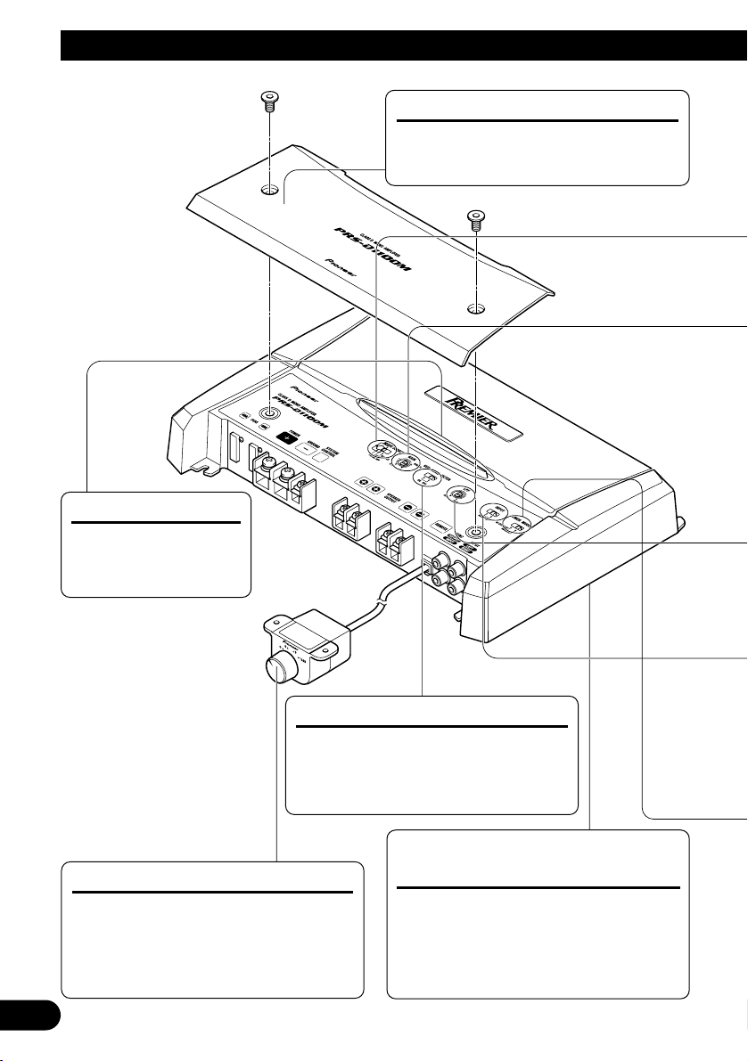
Setting the Unit
Power Indicator
The power indicator
lights when the power
is switched on.
Terminal Cover
Before setting up the unit, unfasten the
screws with a 4 mm hexagonal wrench
and remove the terminal cover.
Bass Boost Control
You can select a bass boost level from
0, 6, 9 and 12 dB.
For instruction of connecting the bass
boost remote control to the amplifier,
see the “Connection Diagram” section.
BFC (Beat Frequency Control)
Switch
BFC switch is on the bottom of the unit.
If you hear a beat while listening to an
AM broadcast with your car stereo,
change the BFC switch using a small
standard tip screwdriver.
Subsonic Select Switch
The subsonic filter cuts inaudible
frequencies below 20 Hz to eliminate
unwanted vibrations and minimize
power loss.
• To adjust the switch, use standard tip screwdriver if needed.
ENGLISH
ESPAÑOL
DEUTSCH
FRANÇAIS
ITALIANO
NEDERLANDS
кмллдав
4
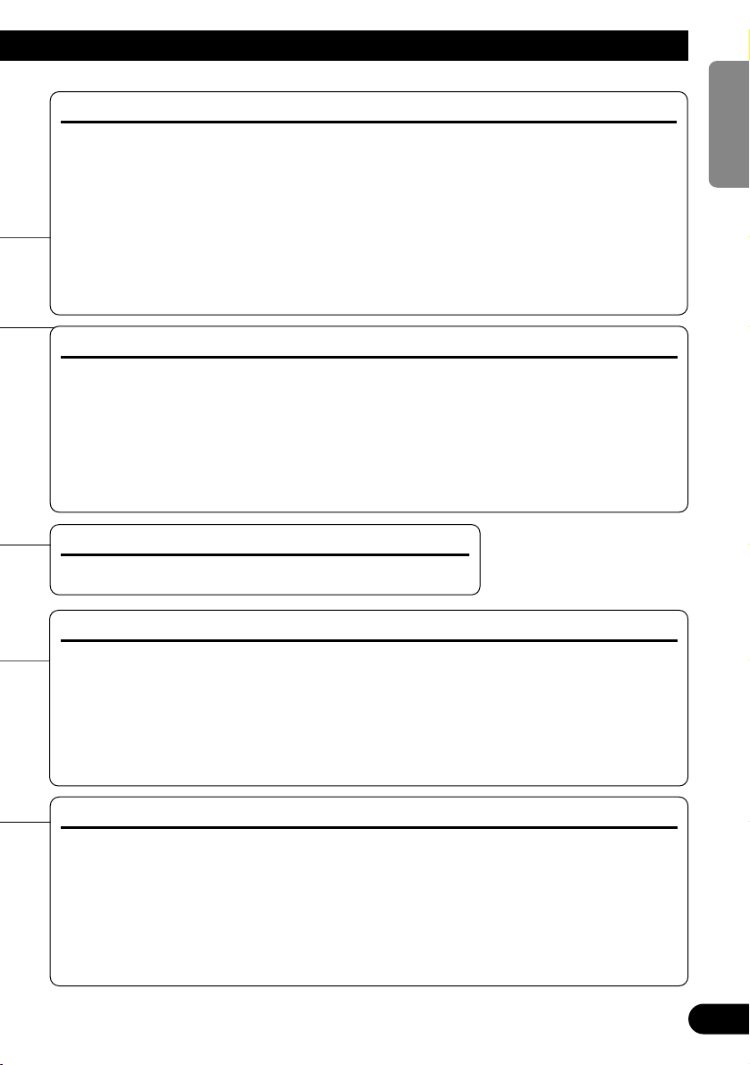
Gain Control
If the sound level is too low, even when the volume of the car stereo used along with this
power amplifier is turned up, turn gain control clockwise. If the sound distorts when the volume is turned up, turn the gain control counter-clockwise.
• When using with an RCA equipped car stereo (standard output of 500 mV), set to the NORMAL
position. When using with an RCA equipped Pioneer car stereo with max. output of 4 V or more,
adjust level to match the car stereo output level.
• If you hear too much noise when using the speaker input terminals, turn the gain control
counter-clockwise.
Input Switch
It is possible to input from a car stereo external output or a car stereo speaker output. Switch
the input switch before turning on the power. Since switching the input switch while the
power is on can cause a loud noise to be emitted from the speakers, the power is turned off
by a protection function. When using an external output, slide the switch to the left. For
connection instructions, see the “Connection Diagram” section. When using a speaker output, slide the switch to the right. In this case, it is necessary to use the supplied speaker input
wire with RCA pin cord. For details, see the “Using the Speaker Input” section.
MODE SELECT Switch
You can select amplifier’s sync mode from MASTER, SYNC and SYNC INV. Set the
MODE SELECT switch to the MASTER position when using one amplifier only. When
using synchronously connecting two or more of these amplifiers in combination, set the first
amplifier to MASTER, and set the remaining amplifiers to SYNC or SYNC INV according
to the manner in which they are connected. The only time the amplifier is switched to the
SYNC INV mode is when amplifiers are synchronously connected with the ex. bridge.
When switching to the SYNC INV mode, the seal over the MODE SELECT switch must be
peeled off and you can find SYNC INV switch. Peel off the seal after checking that connections are correct. See the “Connecting the Speaker Wires” section for details on the MODE
SELECT switch.
POWER MODE Switch
When using speakers with synthetic impeadance 2 Ωto 8 Ω, slide the switch to the right
(NORMAL). When using speakers with synthetic impeadance from 1
Ω
to less than 2 Ω,
slide the switch to the left (HI-CURRENT). These settings are only used when using a single amplifier. See the “Connecting the Speaker Wires” section when combining the use of
multiple amplifiers.
If the speaker impedance exceeds 2
Ω
(4 Ωwhen using ex. bridge), although the POWER
MODE switch be may set to the HI-CURRENT position, setting to the NORMAL position
makes it possible to enjoy high power sound.
Cut Off Frequency Control for LPF
You can select a cut off frequency from 40 Hz to 240 Hz.
5
Connecting the Unit
CAUTION:
To prevent damage and/or injury
• Do not ground the speaker wire directly or connect a negative (–) lead wire for several speakers.
• This unit is for vehicles with a 12-volt battery and
negative grounding. Before installing it in a recreational vehicle, truck or bus, check the battery
voltage.
• If the car stereo is kept on for a long time while
the engine is at rest or idling, the battery may go
dead. Turn the car stereo off when the engine is at
rest or idling.
• If the system remote control wire of the amplifier
is connected to the power terminal through the
ignition switch (12 V DC), the amplifier will
always be on when the ignition is on— regardless
of whether the car stereo is on or off. Because of
this, the battery could go dead if the engine is at
rest or idling.
• DO NOT connect a subwoofer with a lower
impedance than specified in the “Connecting the
Unit” section. Amplifier damage, smoke, and
overheating could result from a non-specified
connection. The amplifier surface could also
become hot to the touch and minor burns could
result.
• Connect either of three subwoofers to the amplifier; 1: a subwoofer with a 420 W or larger nominal input and an impedance 4 Ω, 2: a subwoofer
with a 600 W or larger nominal input and an
impedance 2 Ω or 3: a subwoofer with a 600 W
or larger nominal input and an impedance 1 Ω. If
the nominal input and impedance are out of the
above ranges, the subwoofer may catch fire, emit
smoke or become damaged.
• Install and route the separately sold battery wire
as far away as possible from the speaker wires.
Install and route the separately sold battery wire,
ground wire, speaker wires and the amplifier as
far away as possible from the antenna, antenna
cable and tuner.
• Cords for this product and those for other products may be different colors even if they have the
same function. When connecting this product to
another product, refer to the supplied manuals of
both products and connect cords that have the
same function.
CAUTION
• Disconnect the negative (–) terminal of the battery to avoid the risk of short-circuit and damage
to the unit.
• Secure the wiring with cable clamps or adhesive
tape. To protect the wiring, wrap adhesive tape
around it where they lie against metal parts.
• Do not route wires where they will get hot, for
example where the heater will blow over them. If
the insulation heats up, it may become damaged,
resulting in a short-circuit through the vehicle
body.
• Make sure that wires will not interfere with moving parts of the vehicle, such as the gearshift,
handbrake or seat sliding mechanism.
• Do not shorten any wires. Otherwise the protection circuit may fail to work when it should.
• Never feed power to other equipment by cutting
the insulation of the power supply wire to tap
from the wire. The current capacity of the wire
will be exceeded, causing overheating.
• Never replace the fuse with one of greater value
or rating than the original fuse. Use of an improper fuse could result in overheating and smoke and
could cause damage to the product and injury
including burns.
ENGLISH
ESPAÑOL
DEUTSCH
FRANÇAIS
ITALIANO
NEDERLANDS
кмллдав
6
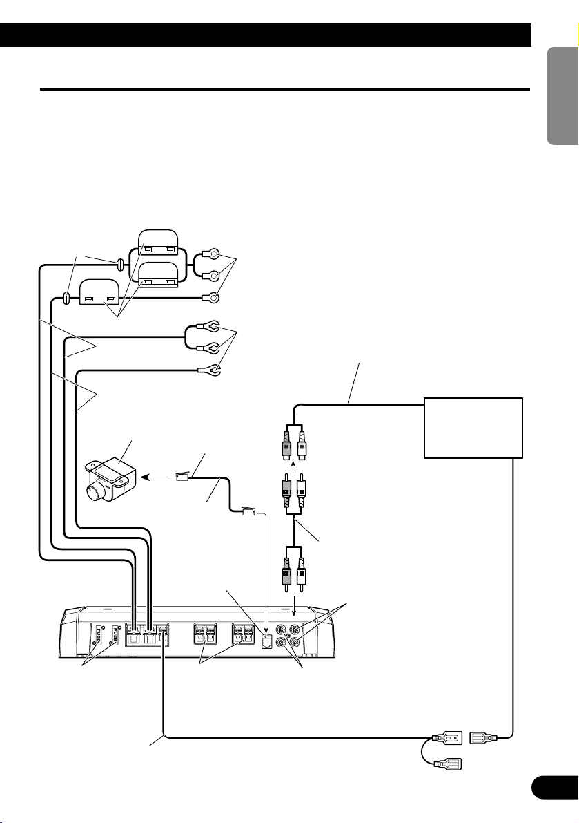
Connection Diagram
• This diagram shows connections using external output. Slide the input switch to the left.
• In the case of connecting the external output from a car stereo to an RCA input, use the jack used for fullrange output. This is because the LPF of the amplifier cannot be turned OFF. If this jack cannot be used,
connect the subwoofer output jack to the RCA input.
• When you connect with speaker output, connections defers from the diagram. For details, see the “Using
the Speaker Input” section. In either case, you need to set the input switch. For details, see the “Setting the
Unit” section.
• Always use the special red battery and ground wire ([RD-223] and [RD-222]), which are sold separately.
Connect the battery wire directly to the car battery positive terminal (+) and the ground wire to the car
body. There is the risk of a fuse burning out if only one of these is connected.
Fuse (40 A)
Car stereo with
RCA output jacks
External Output
Connecting wire with RCA
pin plugs (sold separately).
RCA input jack
System remote control wire (sold separately)
Connect the male terminal of this wire to the system remote control terminal of the car
stereo (SYSTEM REMOTE CONTROL). The female terminal can be connected to the
auto-antenna relay control terminal. If the car stereo does not have a system remote control
terminal, connect the male terminal to the power terminal through the ignition switch.
Speaker output terminal
See the “Connecting the
Speaker Wires” section for
speaker connection instructions.
Bass Boost Remote
Control Wire
Bass Boost
Remote Control
6 m (19 feet 8 inch)
Jack for the bass boost
remote control
Connect this jack and
the bass boost remote
control with the bass
boost remote control
wire.
SYNC OUTPUT/SYNC INPUT jack
See the “Connecting the Speaker Wires”
section for SYNC OUTPUT/SYNC
INPUT jack connection instructions.
Fuse (30 A) × 3
Grommet
Special red battery wire
After making all other connections at the amplifier,
connect the battery wire terminal of the amplifier to
the positive (+) terminal of the battery.
Ground wire (black)
Connect to metal body or chassis.
[RD-223]
(sold separately)
[RD-222] (sold separately)
7
Connecting the Unit
Connecting the Power Terminal
• Always use the special red battery and ground
wire ([RD-223] and [RD-222]), which are sold
separately. Connect the battery wire directly to
the car battery positive terminal (+) and the
ground wire to the car body. There is the risk of a
fuse burning out if only one of these is connected.
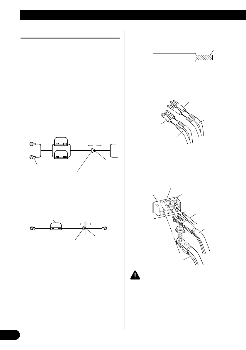
1. Pass the battery wire from the
engine compartment to the interior
of the vehicle.
• After making all other connections to the
amplifier, connect the battery wire terminal
of the amplifier to the positive (+) terminal of
the battery.
[RD-223]
[RD-222]
2. Twist the battery wire, ground wire
and system remote control wire.
3. Attach lugs to wire ends. Lugs not
supplied.
• Use pliers, etc., to crimp lugs to wires.
4. Connect the wires to the terminal.
• Fix the wires securely with the terminal
screws.
WARNING
Failure to securely fasten the battery wire to the terminal using the terminal screws could cause the terminal area to overheat and could result in damage
and injury including minor burns.
GND terminal
Power terminal
Battery wire
System remote
control terminal
System remote
control wire
Ground wire
Twist
Battery wire
Ground wire
Lug
Lug
Fuse (30 A)
Engine
compartment
Interior of
the vehicle
Drill a 14 mm
(1/2 inch) hole
into the vehicle
body.
Insert the O-ring rubber
grommet into the vehicle
body.
Positive terminal
Fuse (30 A)
Fuse (30 A)
Engine
compartment
Interior of
the vehicle
Drill an 8 mm
(3/8 inch) hole
into the vehicle
body.
Insert the O-ring rubber
grommet into the vehicle
body.
Positive terminal
ENGLISH
ESPAÑOL
DEUTSCH
FRANÇAIS
ITALIANO
NEDERLANDS
кмллдав
8
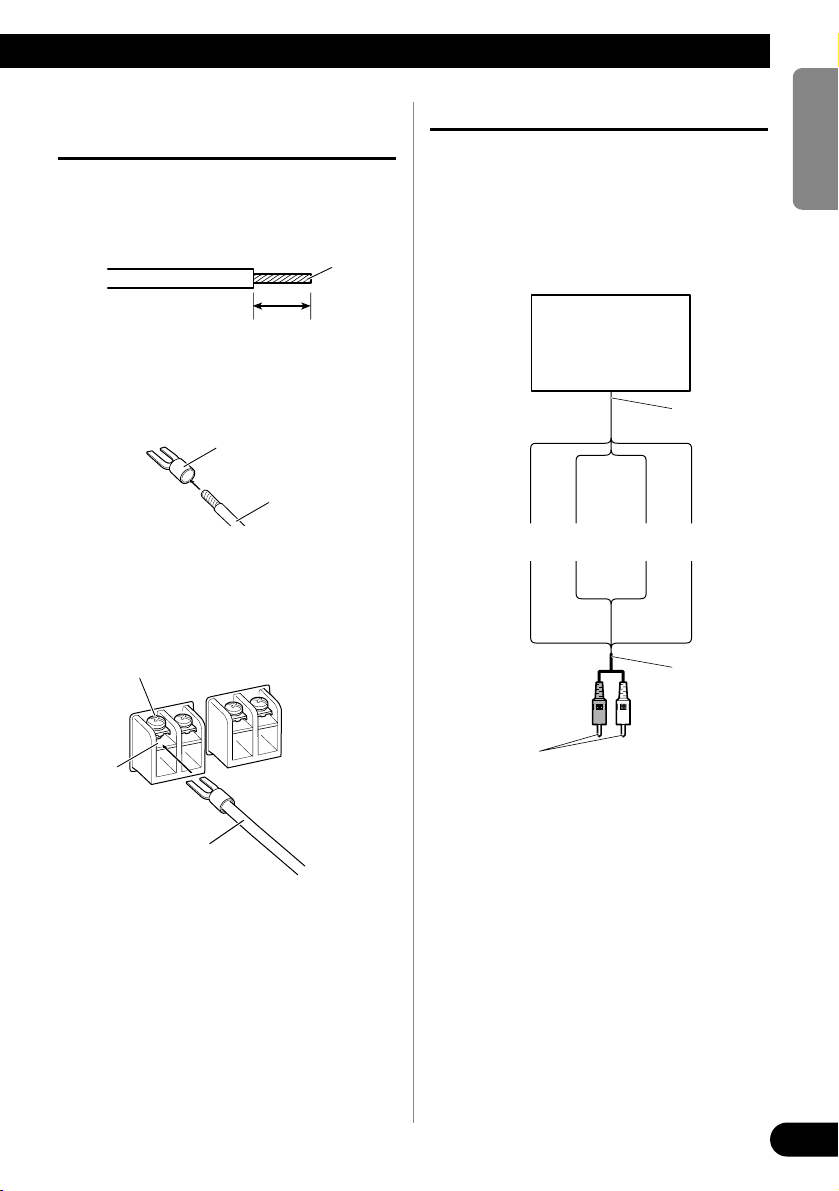
Connecting the Speaker Output
Terminals
1. Expose the end of the speaker wires
using nippers or a cutter by about
10 mm (3/8 inch) and twist.
2. Attach lugs to speaker wire ends.
Lugs not supplied.
• Use pliers, etc., to crimp lugs to wires.
3. Connect the speaker wires to the
speaker output terminals.
• Fix the speaker wires securely with the termi-
nal screws.
Using the Speaker Input
Connect the car stereo speaker output
wires to the amplifier using the supplied
speaker input wire with RCA pin cord.
• Slide the input switch to the right.
7 Connections when using the speaker
input
• As a result of connecting the car stereo speaker
output wire to the amplifier, the power of the
amplifier is turned on automatically when the car
stereo is turned on. It is not necessary to connect
the system remote control wire in this case.
• In the case the amplifier and head unit are connected using a speaker input wire with RCA pin
cord, the amplifier power is only turned on when
one amplifier is being used. If two or more amplifiers are synchronously connected in combination, connect the head unit and all of the amplifiers with the system remote control wire.
Note:
• Connect the system remote control wire when the
power of the amplifier is not to be turned on
when the car stereo is turned on.
10 mm
(3/8 inch)
Twist
Speaker wire
Lug
Speaker
output
terminal
Terminal screw
Speaker wire
Speaker
output
Car Stereo
Speaker input
wire with RCA
pin cord
To RCA input
jack of this unit.
White: Black: Black: Red:
Left + Left ≠ Right ≠ Right +
9
Connecting the Unit
Connecting the Speaker Wires
Connect the speaker leads and set MODE SELECT switch and POWER MODE switch to suit the configuration according to the figures shown below and the next page.
• When synchronously connecting two or more amplifiers in combination, only use these amplifiers. Do not
mix these amplifiers with other amplifiers.
• When synchronously connecting two or more amplifiers in combination, set the gain control, subsonic
select switch, cut off frequency control for LPF and bass boost control on the amplifier that has been set to
MASTER with the MODE SELECT switch. These settings are inactive when set on an amplifier set to
SYNC or SYNC INV.
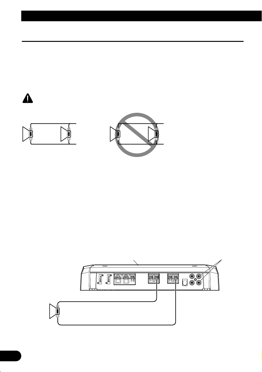
CAUTION
Do NOT install or use this amplifier by wiring speakers rated at 2 Ω (or lower) in parallel to achieve a 1 Ω (or
lower) bridged mode (Diagram B).
Amplifier damage, smoke, and overheating could result from improper bridging. The amplifier surface could
also become hot to the touch and minor burns could result.
To properly install or use a bridged mode and achieve a 2 Ω load, wire two 4 Ω speakers in parallel with Left
+ and Right – (Diagram A) or use a single 2 Ω speaker.
If the synthetic impedance is from 2 Ω to less than 4 Ω, always make sure to set the POWER MODE switch to
the HI-CURRENT position.
In addition, refer to the speaker instruction manual for information on the correct connection procedure.
Single Amplifier
• Use speakers having an impedance from 1 Ω to 8 Ω.
• The setting of the POWER MODE switch varies according to the speaker impedance. See the “Setting the
Unit” section for details.
r
MODE SELECT switch must
be in MASTER position.
Connect to a car stereo.
For details, see the “Connection Diagram”.
1 Ω to 8 Ω
Diagram A - Proper
Diagram B - Improper
4 Ω
Speaker
2 Ω Bridged Mode
4 Ω
Speaker
2 Ω
Speaker
1 Ω Bridged Mode
2 Ω
Speake
ENGLISH
ESPAÑOL
DEUTSCH
FRANÇAIS
ITALIANO
NEDERLANDS
кмллдав
10
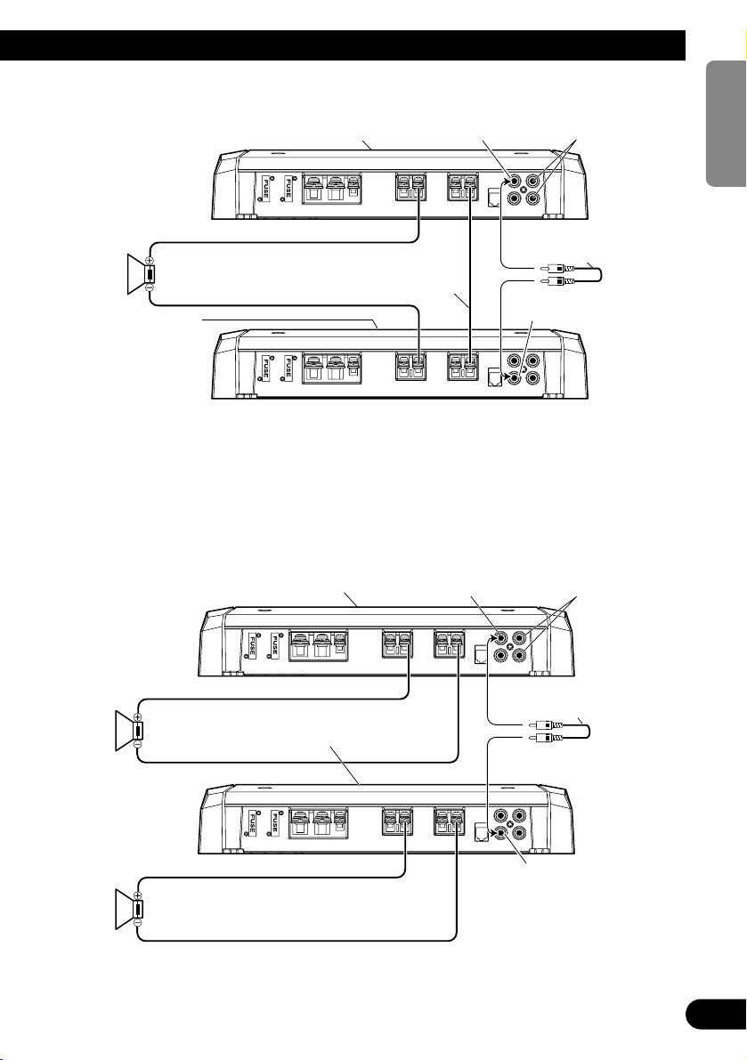
Two Amplifier (Ex. Bridge)
• Only use speakers having an impedance of 2 Ω to 16 Ω. In addition, in the case of connecting multiple
speakers with a bridge, check that the synthetic impedance is at least 2 Ω.
• The setting of the POWER MODE switch varies according to the speaker impedance. Slide the POWER
MODE switch to the HI-CURRENT position if the impedance is from 2 Ω to less than 4 Ω, or slide it to the
NORMAL position if the impedance is from 4 Ω to 16 Ω. The same setting is used for both amplifiers.
• When switching to the SYNC INV mode, the seal over the MODE SELECT switch must be peeled off and
you can find SYNC INV switch. Peel off the seal after checking that connections are correct.
Two Amplifier
• Use speakers having an impedance from 1 Ω to 8 Ω.
• The setting of the POWER MODE switch varies according to the speaker impedance. See the “Setting the
Unit” section for details. The same setting is used for both amplifiers.
MODE SELECT switch
must be in SYNC INV
position.
Connecting wire with RCA
pin plugs (sold separately).
Connecting
speaker wire
(sold separately).
MODE SELECT switch
must be in SYNC position.
MODE SELECT switch must
be in MASTER position.
Connect to a car stereo.
For details, see the
“Connection Diagram”.
2 Ω to 16 Ω
1 Ω to 8 Ω
1 Ω to 8 Ω
SYNC OUTPUT
MODE SELECT switch must
be in MASTER position.
Connect to a car stereo.
For details, see the
“Connection Diagram”.
Connecting wire with RCA
pin plugs (sold separately).
SYNC INPUT
SYNC OUTPUT
SYNC INPUT
11
Connecting the Unit
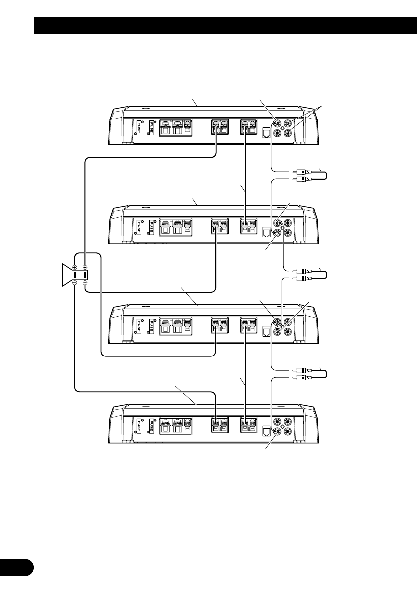
Four Amplifier (Ex. Bridge)
MODE SELECT switch
must be in MASTER position.
Connecting wire with RCA
pin plugs (sold separately).
MODE SELECT switch must
be in SYNC INV position.
Connect to a car stereo.
For details, see the
“Connection Diagram”.
MODE SELECT switch must be
in SYNC INV position.
MODE SELECT switch must
be in SYNC INV position.
Connecting wire with RCA
pin plugs (sold separately).
Connecting wire with RCA
pin plugs (sold separately).
Connecting speaker
wire (sold separately).
Connecting speaker
wire (sold separately).
SYNC OUTPUT
SYNC INPUT
SYNC OUTPUT
SYNC INPUT
2 Ω to
16 Ω
• Only use speakers having an impedance of 2 Ω to 16 Ω. In addition, in the case of connecting multiple
speakers with a bridge, check that the synthetic impedance is at least 2 Ω.
• The setting of the POWER MODE switch varies according to the speaker impedance. Slide the POWER
MODE switch to the HI-CURRENT position if the impedance is from 2 Ω to less than 4 Ω, or slide it to the
NORMAL position if the impedance is from 4 Ω to 16 Ω. The same setting is used for four amplifiers.
• When switching to the SYNC INV mode, the seal over the MODE SELECT switch must be peeled off and
you can find SYNC INV switch. Peel off the seal after checking that connections are correct.
SYNC OUTPUT
SYNC INPUT
12
ENGLISH
ESPAÑOL
DEUTSCH
FRANÇAIS
ITALIANO
NEDERLANDS
кмллдав
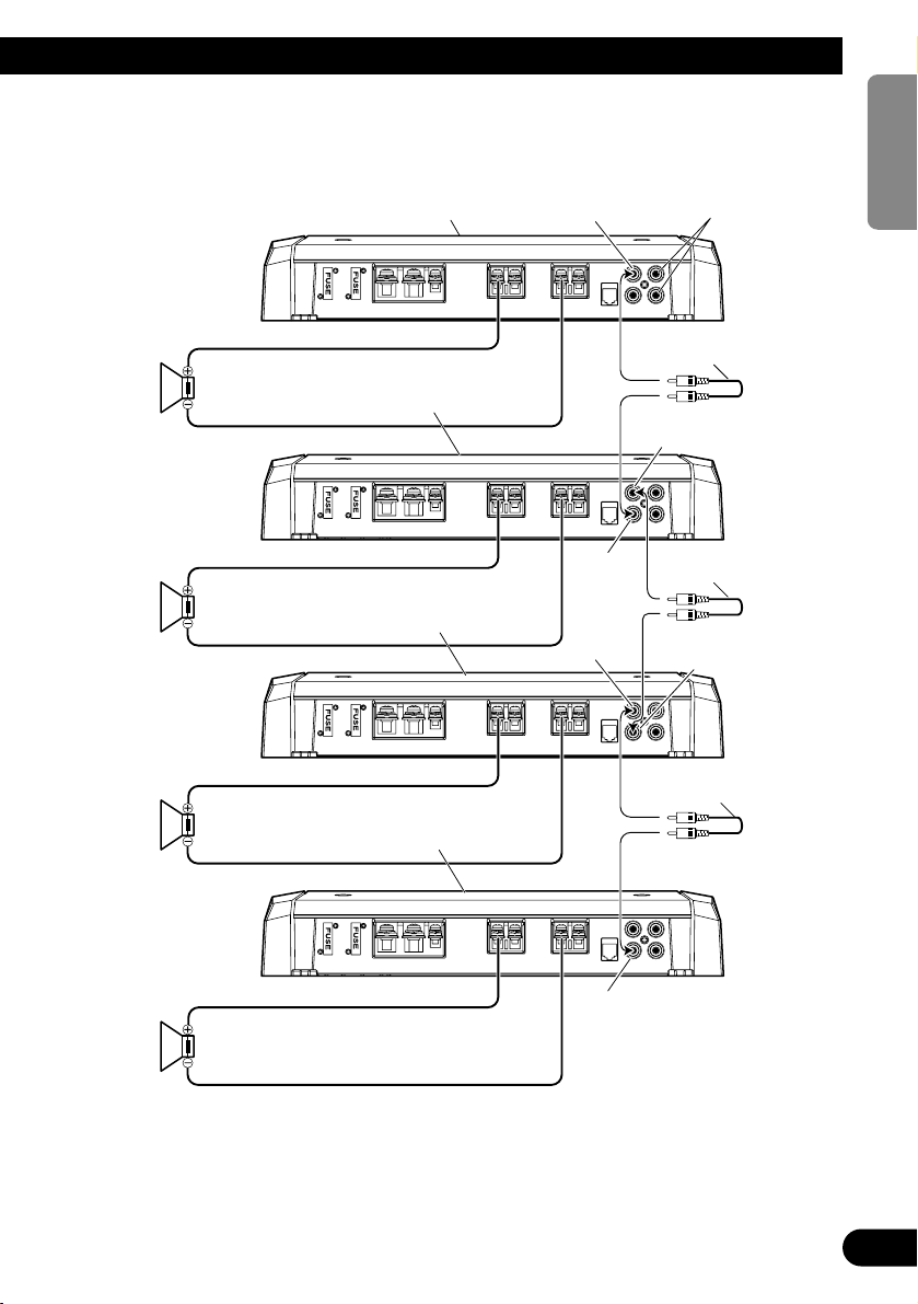
Four Amplifier
MODE SELECT switch
must be in MASTER position.
Connect to a car stereo.
For details, see the
“Connection Diagram”.
Connecting wire with RCA
pin plugs (sold separately).
Connecting wire with RCA
pin plugs (sold separately).
Connecting wire with RCA
pin plugs (sold separately).
MODE SELECT switch
must be in SYNC position.
MODE SELECT switch
must be in SYNC position.
MODE SELECT switch
must be in SYNC position.
1 Ω to 8 Ω
1 Ω to 8 Ω
1 Ω to 8 Ω
1 Ω to 8 Ω
SYNC OUTPUT
SYNC
INPUT
SYNC
OUTPUT
SYNC INPUT
• Use speakers having an impedance from 1 Ω to 8 Ω.
• The setting of the POWER MODE switch varies according to the speaker impedance. See the “Setting the
Unit” section for details. The same setting is used for four amplifiers.
SYNC OUTPUT
SYNC INPUT

13
Installation
CAUTION
• Do not install in:
—Places where it could injure the driver or pas-
sengers if the vehicle stops suddenly.
—Places where it may interfere with the driver,
such as on the floor in front of the driver’s
seat.
• Make sure that wires are not caught in the sliding
mechanism of the seats, resulting in a short-circuit.
• Confirm that no parts are behind the panel when
drilling a hole for installation of the amplifier.
Protect all cables and important equipment such
as fuel lines, brake lines and electrical wiring
from damage.
• Install tapping screws in such a way that the
screw tip does not touch any wire. This is important to prevent wires from being cut by vibration
of the car, which can result in fire.
• DO NOT allow amplifier to come into contact
with liquids due to, for example, the location
where the amplifier is installed. Electrical shock
could result. Also, amplifier and speaker damage,
smoke, and overheating could result from contact
with liquids. In addition, the amplifier surface and
the surface of any attached speakers could
become hot to the touch and minor burns could
result.
• To ensure proper installation, use the supplied
parts in the manner specified. If any parts other
than the supplied ones are used, they may damage
internal parts of the amplifier, or they may
become loose causing the amplifier to shut down.
• Never replace the fuse with one of greater value
or rating than the original fuse. Use of an improper fuse could result in overheating and smoke and
could cause damage to the product and injury
including burns.
CAUTION:
To prevent malfunction and/or injury
• To ensure proper heat dissipation of the amplifier,
be sure of the following during installation.
—Allow adequate space above the amplifier for
proper ventilation.
—Do not cover the amplifier with a floor mat or
carpet.
• DO NOT allow amplifier to come into contact
with liquids due to, for example, the location
where the amplifier is installed. Electrical shock
could result. Also, amplifier and speaker damage,
smoke, and overheating could result from contact
with liquids. In addition, the amplifier surface and
the surface of any attached speakers could
become hot to the touch and minor burns could
result.
• Do not install the amplifier on unstable places
such as the spare tire board.
• The best location for installation differs with the
car model and installation location. Secure the
amplifier at a sufficiently rigid location.
• Make temporary connections first and check that
the amplifier and the system operate properly.
• After installing the amplifier, confirm that the
spare tire, jack and tools can be easily removed.
14
ENGLISH
ESPAÑOL
DEUTSCH
FRANÇAIS
ITALIANO
NEDERLANDS
кмллдав
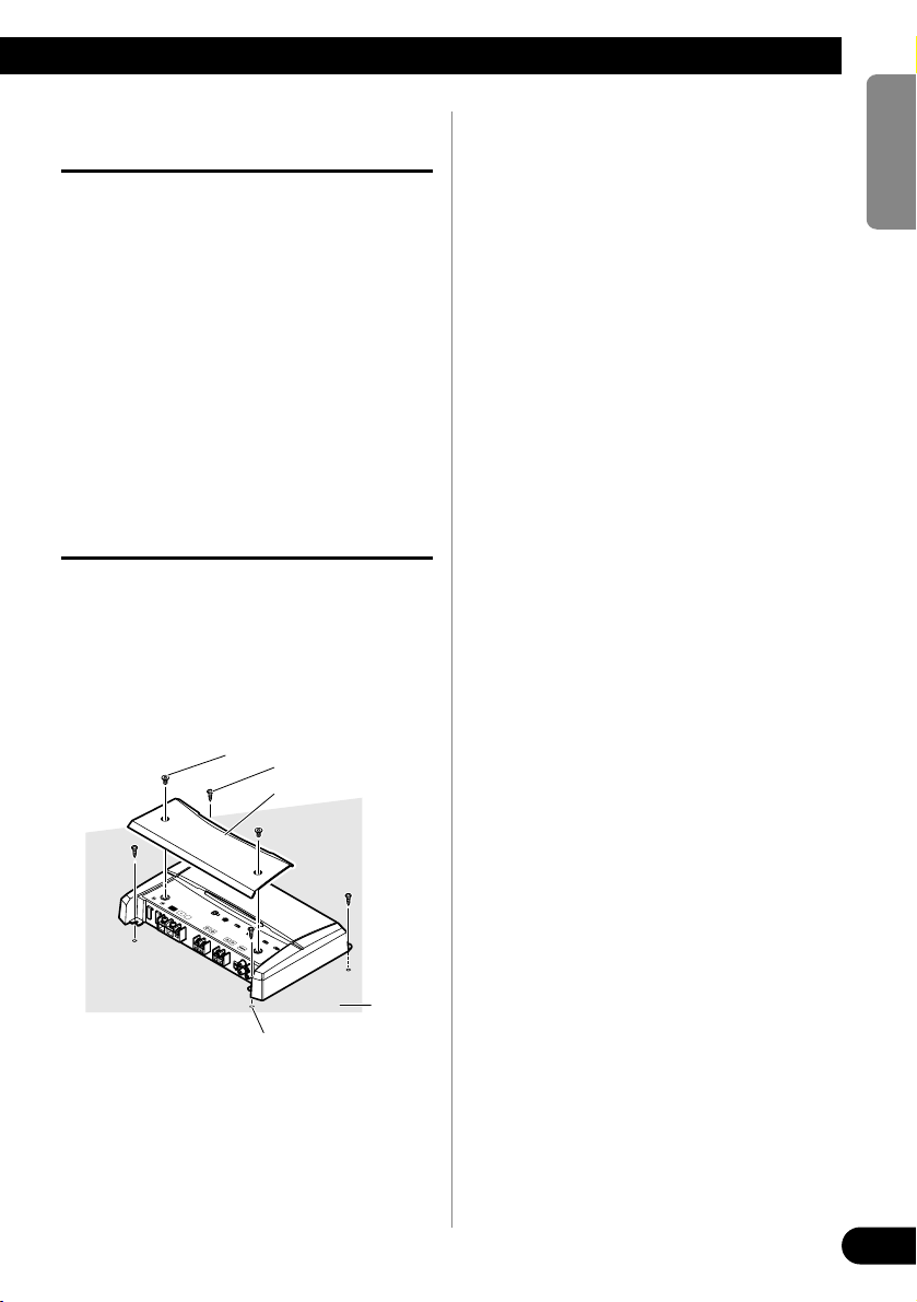
Example of installation on the floor
mat or on the chassis
1. Place the amplifier where it is to be
installed. Insert the supplied tapping screws (4 × 18 mm) into the
screw holes. Push on the screws with
a screwdriver so they make marks
where the installation holes are to
be located.
2. Drill 2.5 mm (1/8 inch) diameter
holes at the point marked, and
install the amplifier, either on the
carpet or directly to the chassis.
Replacing the terminal cover
1. Align the unit and terminal cover,
and insert the screw.
2. Tighten the screw with a 4 mm
hexagonal wrench.
Drill a 2.5 mm (1/8 inch)
diameter hole
Tapping-screws
(4 × 18 mm)
Floor mat
or chassis
Screw
Terminal Cover
 Loading...