

Page 1
PNR 14-150
OPERATION MANUAL
15" Single Surface
Thickness Planer
©2006 Pioneer Supply International Inc.
Page 2

CONTACT INFORMATION .........................................................................................3
SECTION 1: SAFETY
General Power Tool Safety Instructions .................................................................. 4-6
Additional Safety for Planers .......................................................................................7
Specification Sheet ......................................................................................................8
Parts Identification .......................................................................................................9
SECTION 2: POWER REQUIREMENTS ..................................................................10
SECTION 3: SET UP
Set Up ......................................................................................................................10
Contents ...................................................................................................................11
Cleaning ....................................................................................................................12
Site Considerations ...................................................................................................12
Moving & Placing Base Unit ......................................................................................12
Extension Wings ........................................................................................................12
Hand Wheel ...............................................................................................................13
Dust Hood .................................................................................................................13
Safety Switch .............................................................................................................14
Gearbox Oil Level ......................................................................................................14
SECTION 4: OPERATIONS / ADJUSTMENTS
Before You Begin ......................................................................................................15
Basic Operation .........................................................................................................15
Operation Tips ...........................................................................................................16
Operating Feed Speed ..............................................................................................16
Adjusting Height / Depth of Cut .................................................................................17
Adjusting Bed Rollers ................................................................................................17
Adjusting Alignment on Pulley ...................................................................................18
Adjusting V-Belt Tension ............................................................................................18
Anti-Kickback Fingers ................................................................................................18
Inspecting Knives ......................................................................................................19
Setting/Replacing Knives ..........................................................................................19
Feed Rollers and Chip Breaker Adjustments ............................................................20
Feed Roller Spring Tension .......................................................................................21
Table Parallelism .......................................................................................................22
2 © 2006 Pioneer Supply International
Page 3

SECTION 5: MAINTENANCE
Maintenance Schedule ..............................................................................................23
Cleaning ....................................................................................................................23
Lubrication .................................................................................................................23
PARTS BREAKDOWN & LISTING ..................................................................... 24-27
WARRANTY AND RETURNS ............................................................................. 28-30
Notes .........................................................................................................................31
Page 4
4 © 2006 Pioneer Supply International
Page 5

Page 6

6 © 2006 Pioneer Supply International
Page 7

Additional Safety for Planers
INSTRUCTION MANUAL: Be aware of correct operation and potential safety hazards. Read and understand
this entire manual before starting the planer.
INFEED CLEARANCE: The infeed roller is always spinning while machine is in operation. Keep hands, clothing, and long hair away from the infeed area to prevent anything from being pulled into the planer and prevent
serious injury.
BODY POSITION: There is a chance that the material or work piece may kick back toward you during operation. Always stand to the side of the planer during the entire operation. NEVER place your face close to planer
to look inside while planer is running.
PLANING MATERIAL: Thickness planers are designed to plane natural solid wood stock. Trying to plane
MDF, plywood, laminates, or other synthetic or man-made products may damage machine or cause injury.
GRAIN: Always plane in the same direction or at a slight angle with the wood grain. Planing across the grain is
hard on the planer and may cause the work piece to kick back.
CLEAN STOCK: Always inspect and clean stock of nails, staples, or loose knots or other debris. This debris
can kick back at the operator and will damage your knives when they contact the cutter head.
CUTTING CAPACITIES: Do not push the planer beyond its listed capacities. Material kick back may result and
injury to operator or damage to machine may result:
• Maximum Depth of Cut ...................... 1/8"
• Minimum Board Length ..................... 12"
• Minimum Board Thickness ................ 1/4"
• Maximum # of Boards at One Time ..... 1
PLANER COVERS: Never remove guards or covers while operating planer. Wood chips fly around inside the
planer at a very high rate of speed and could cause seriously injury.
!
JAMMED WORK PIECES:
jams. Never attempt to remove jammed work pieces and never reach into dust hood to remove clogs when the
planer is running serious injury may result.
DULL/DAMAGED KNIVES: Dull or damaged knives will not only give poor finish results but may kick back,
that can cause personal injury.
CHANGING KNIVES: Disconnect machine from power source.
handle them with care.
MAKING ADJUSTMENTS:
disconnected from power source before performing any service or maintenance to the machine. Failure to do
so may cause serious personal injury.
WARNING: Always stop the planer and disconnect power before removing
!
CAUTION: Planer knives are sharp,
!
WARNING: Magnetic switches may start when bumped. Make sure planer is
!
PLANER USE:
result in serious personal injury, damage to equipment, or poor work results.
WARNING:Do not use this planer for other than its intended use. Failure to do so could
Page 8

SPECIFICATION SHEET
PNR 14-150 15" Single Surface Thickness Planer
Item Number PNR 14-150
Description 15" Single Surface Thickness Planer
Motor HP 3hp, 220v, 1ph, 18A
Table size 15" x 19-7/8"
Footprint (less extensions) 23" x 21"
Overall width 26-5/16"
Height 47-1/4"
Knives 3 HSS
Cutter head speed 5000rpm
Cutter head diameter 2-7/8"
Maximum cutting depth 1/8"
Maximum planing width 14-7/8"
Maximum planing height 6"
Cuts per minute 15,000cpm
Feed rate - 2 speeds 16fpm & 20fpm
Maximum cuts per inch 62
Minimum stock height 1/4"
Minimum stock length 8"
Appx Net Weight 500lbs
Approx Shipping Weight 560lbs
FEATURES: INCLUDES:
Extra-large hand wheel Knife setting gauge
Spring loaded cutter head for easy knife setting Infeed/outfeed extensions
Two chromed return rollers Top return rollers
Three roller extension wing 4" dust port
Two positive table locks Magnetic switch w/thermal overload
One-piece cabinet style stand
Infeed rollers: Spiral-serrated
Outfeed rollers: Machined
Power transfer: Triple belt drive
Two adjustable bed rollers
Scratch resistant powder-coated paint
NOTE: We make every effort to be accurate with our specifications, copy, images and other product information and apologize for
any errors that may occur. This information while deemed accurate is not guaranteed. We reserve the right to make changes to all
products including specifications, pricing and availability.
Pioneer Supply International, Inc.
P.O. Box 12308
Salem, OR 97309
8 © 2006 Pioneer Supply International
Page 9
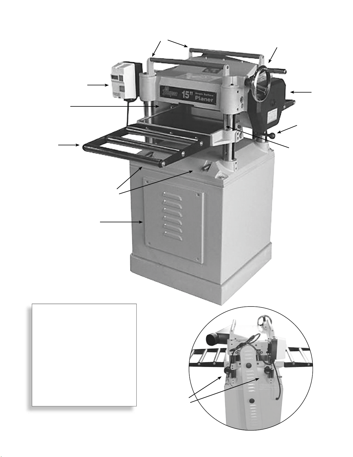
Parts Identifi cation - PNR 14-150
A
K
E
B
C
D
G
F
I
J
A Magnetic Switch
B Return Rollers
C Table Height Hand wheel
D Gearbox
E Extension Wing
F Table Height Scale
G Speed Control Knob
H Table Locks - Figure 2
I Lifting Bars
J Motor Access Cover
K V-Belt Cover
Figure 1
H
Figure 2
Page 10

SECTION 2: Power Requirements
WARNING: Machine must be grounded properly to prevent electrocution or fire. Ensure your
electrical configuration complies with local and state codes. Contact qualified electrician to ensure
!
compliance. DO NOT connect the machine to the power source until instructed to do so, as serious
personal injury could occur.
220V Single-Phase Grounding
All electrical connections must be made in accordance with local codes. Grounding reduces the risk of electric
shock if an electrical short happens. This machine has a power cord that has a grounding wire, which must
be properly connected to the grounding prong on the plug. NOTE: The outlet must be properly installed and
grounded for this to operate properly.
Amperage Draw / Minimum Circuit Requirements
The motor on the PNR 14-150 will draw 18 amps during operation. Only connect your machine to a circuit
that meets the requirements. Always check to see if the wires and circuit breaker in your circuit are capable
of handling the amperage draw from your machine, as well as any other machines that could be operating on
the same circuit. If you are unsure, consult a qualified electrician. NOTE: Start up amperage draw is significantly higher than running draw.
Plug Type / Extension Cords
An L6-20 plug and receptacle is recommended to connect your machine to power. It is NOT recommend using
extension cords on 220V equipment. Instead, arrange the placement of your equipment and the installed wiring
to eliminate the need for extension cords. If you find it absolutely necessary to use an extension cord at 220V
with your machine, check with a qualified electrician for the correct sizing, gauge, type, and maximum possible
length for your needs.
SECTION 3: Set up
WARNING: This planer is a heavy machine (560 lbs. shipping weight). DO NOT over-exert yourself
while unpacking or moving this machine. To be safe, you will need assistance and power equipment when moving the shipping crate and removing the machine from the crate. Safety glasses
!
The Pioneer PNR 14-150 was carefully packed when it left the warehouse. If you discover the machine is
damaged after you have signed for delivery, please call your supplier immediately. Save the containers and all
packing materials for possible inspection by the carrier or its agent. Photograph any damage. Otherwise, filing a freight claim can be difficult. When you are completely satisfied with the condition of your shipment, you
should inventory the contents before beginning set up process.
should be worn during the entire set up process. Read through this entire manual to become familiar with the set up, controls and operations before starting the machine.
In the event that any nonproprietary parts are missing (e.g. a nut or a washer), contact your supplier, or for
the sake of expediency, replacements can be obtained at your local hardware store.
The following items are needed to complete the set up process, but are not included with your machine:
4' straightedge or longer, dial indicator, phillips screwdriver, flat head screwdriver, plug and receptacle.
10 © 2006 Pioneer Supply International
Page 11

Contents - PNR 14-150
A
A Planer
B Extension Wings
C Dust Hood
D Dust Hood Hardware
E Hand Wheel
F Hand Wheel Hardware
G Knife Setting Guide Shaft
H Open End Wrenches:
8-10, 12-14, 17-19mm
I Allen Wrenches: 3,4,5,6mm
J Set Screws for Extension Wings (6)
K Bolts for Extension Wings (6)
M Washers (6)
H
E
B
C
F
G
J K
I
D
L
Figure 3
Page 12

Cleaning
The unpainted surfaces are coated with a waxy oil to protect them from corrosion during shipment. Remove
this protective coating with a solvent cleaner or citrus-based degreaser to clean thoroughly, some parts may
need to be removed. For optimum performance from your machine, make sure you clean all moving parts
or sliding contact surfaces that are coated. Avoid chlorine-based solvents, such as acetone or brake parts
cleaner, as they may damage painted surfaces should they come in contact. Always follow the manufacturer’s
instructions when using any type of cleaning product. These items are coated and must be cleaned:
Cutter head, Table, Feed Rollers, and Extension Wings.
WARNING: Gasoline and petroleum products have low flash points and could cause an explosion or fire if used to clean machinery. DO NOT use gasoline or petroleum products to clean the
!
machinery. Many of the solvents commonly used to clean machinery can be toxic when inhaled or
ingested. Lack of ventilation while using these solvents could cause serious personal health risks
or fire. Take precautions from this hazard by only using cleaning solvents in a well ventilated area.
Site Considerations
!
WARNING: DO NOT allow unsupervised children or visitors in shop at any time.
Floor Load
The PNR 14-150 has a shipping weight of 560 lbs (254Kg), net weight of 500 lbs (226.8Kg), and a
base footprint of 32" x48".
Working Space
I
n order to have a safe working environment,
should be enough space around the machine to
walk around the machine and enough room to plane
material both at the infeed and outfeed sides without
bumping into other people, machines and obstructions.
See Figure 4.
there
Figure 4
Moving & Placing Planer
The cabinet stand on the PNR 14-150 is equipped with lifting bars (Refer to page 9) to lift and place the planer. When lifting the planer with a forklift, place shop rags or cardboard between the forks and cabinet base so
you do not scratch the paint.
Extension Wings
You will need:
Two Table Extension Wings, 6 x Hex Bolts, 6 x
Lock Washers, 6 x Flat Washers. 4 x Set Screws.
To attach the table extension wings:
1 Install set screws in the holes in the side of the
wings (see Figure 5).
2 Attach the table extension wings to the planer table
with the hex bolts, lock washers, and flat washers,
as shown in Figure 6, but do not fully tighten the
12 © 2006 Pioneer Supply International
Figure 5
Page 13

3 Using a straightedge as a guide and the set screws
for leveling control, position the extension wings
even with the table, then fully tighten the hex bolts.
NOTE: Be aware that the bed rollers will give you a
false
reading with your straightedge if they are raised
above the table. Move them down or work around them
when leveling the extension wings.
Hand Wheel
You will need:
Hand wheel, Hand wheel Bushing, Hand wheel Handle,
Hex Nut, Flat Washer
To install the Hand wheel:
1 Place the bushing on the Hand wheel shaft.
2 Insert the key into the shaft keyway.
3 Screw the handle into the Hand wheel.
4
Place the Hand wheel on the shaft and secure it with
the hex nut and flat washer, as shown in Figure 7.
Figure 6
Dust Hood
IMPORTANT: If you are not using a dust
collection system, do not use plastic dust
!
You will need:
Dust Hood, 3 x Hex Bolts, 3 x Cap Screws, 6 x Flat
Washers, 3 x Hex Nuts, 6 x Flange Bolts
To install the dust hood:
1 Attach the dust hood to the top of the planer with
the hex bolts, flat washers, and hex nuts as shown
in Figure 8. NOTE: You will need to reach into the
dust hood to get access for fastening the nuts.
2 Attach the bottom of the dust hood to the planer
with the cap screws.
3 If you have a dust collector, attach it to the dust
hood now. NOTE: To maximize work results and
minimize clogging, chip out, etc., use a dust
collector with your planer.
hood to direct chips. We reccomend to
always use a dust collector when operating
this planer.
Figure 7
Figure 8
Page 14

Safety Switch
NOTE:
should not be replaced by a standard power switch. If the
power goes out, the magnetic switch prevents the machine
from starting when the power is returned, and protects the
operator from an accidental start and possible injury.
Gearbox Oil Level
To check the gearbox oil level:
1 Remove the gearbox fill plug (Figure 11).
2 Using the short end of the hex wrench, dip it inside the fill hole and remove it. If the end of the hex wrench
3 Replace the fill plug and skip to the next section. If the end of the hex wrench is not coated with oil, then
The magnetic switch is there for your safety and
WARNING: Before starting your machine for the first time, make sure the gearbox has oil. The
!
is coated with oil, then the gearbox oil level is okay.
you need to add more oil. Refer to maintenance section of this manual for instructions on how add or drain oil.
proper oil level is just even with the bottom of the fill plug hole. The gearbox uses 80W-90W gear oil.
Figure 9
NOTE: Replace the gearbox oil after the first 20 hours of operation. This is a normal break-in procedure.
Fill Plug
Drain
Figure 10
Figure 11
14 © 2006 Pioneer Supply International
Page 15

SECTION 4: Operations / Adjustments
Your Pioneer thickness planer has been fully adjusted at the factory and no further setup is required to operate your machine. However, because of handling and transit, some of these adjustments may need to be
repeated to ensure optimum cutting results. Keep this in mind as you start to use your new planer.
!
IMPORTANT: If you have never used a planer before, it is strongly recommended that you become confi-
dent of your personal understanding of how this machine operates and how it is adjusted.
Before You Begin
1 Read the entire instruction manual, and make sure oil is in the gearbox.
2 Make sure all tools and foreign objects have been removed from the machine.
3 Put on safety glasses, and secure loose clothes or long hair.
4 Connect your planer to the power source.
5 Press the on button on the Magnetic switch.
The planer should run smoothly with little or no vibration.
• After if you suspect any problems, immediately stop the planer by pushing the red button.
• Disconnect planer from power source before performing any trouble shooting or maintenance.
• If you need any help with your planer call your supplier.
Basic Operations
WARNING: Loose hair and clothing could get caught in machinery and cause serious personal
injury. Keep loose clothing rolled up and long hair tied up and away from machinery. Damage to
!
NOTE: The table moves approximately 1/16" (1.59mm) with one turn of the Hand wheel.
The basic steps of operating the planer are as follows:
1 Always wear safety glasses, hearing protectors and respirator.
2 Unless your work piece is very flat, surface plane the work piece on a jointer until it is flat—having the face
flat will ensure that it sits flat on the planer table during operation.
3 Start the planer.
4 Adjust the table height to slightly lower than your work piece height to ensure the first cut is as light as
possible (approximately 1/32" to 1/16" or .8mm to 1.59mm).
5 Place the flat side of the board down on the table, and feed the work piece through the planer, making
sure not to stand directly in front or behind the work piece to avoid kickback injury. NOTE: If the cut is
too heavy and bogs down the planer, turn the planer off immediately, allow it to come to a complete stop,
remove the work piece, and repeat Steps 4 & 5.
6 Measure your work piece thickness and adjust the table height as necessary to take
pass, depending on your needs. For most wood types, 1/16"
your eyes, lungs, and ears could result from using this machine without proper protective gear.
Always wear safety glasses, a respirator, and hearing protection when operating this machine.
a lighter or heavier
(1.59mm)
per pass is a good cutting depth.
NOTE: Any time you switch directions, either up or down, with the hand wheel, there will be a small amount
of play. This will be slightly less than 1/16" (1.59mm). However, as long as you move the hand wheel in the
same direction during operation, this will not be a factor.
Page 16

Operation Tips
¸ Lumber should be clean and dry. Inspect for defects like loose knots, warping, cupping, twisting, glue and
for foreign objects (nails, staples, imbedded gravel, etc,). If you have any question about the quality of
your lumber, do not use it. Wood with more than 20% moisture content or wood exposed to rain or snow,
will plane poorly and leave a feathery surface. Wet wood causes excessive wear to the knives and motor
and can also hasten rust and corrosion.
¸ In order to create even wear on the blades, alternate between the left, the right, and the middle when feed-
ing lumber into the planer. Your knives will remain sharp much longer and you won't get worn spots on the
blades.
¸ Plane ONLY natural wood fiber. No wood composites such as plywood, chipboard etc.
¸ Plane with the grain. Never feed end-cut or end-grained lumber into your planer.
¸ Avoid boards with loose knots, splits, cross grain or other obvious blemishes or defects. They can damage
the blades and pose the possibility of operator injury.
¸ Keep your work area clear and clean.
¸ Use the stock return rollers to move material from the outfeed area back to the infeed area when working
on long stock.
Operating Feed Speed
The infeed and outfeed rollers move the stock through
the planer while keeping boards flat and providing a
consistent rate of feed and pressure. Use the different
feed rates as stated below:
Low Feed Rate .............................Dimensioning Pass
High Feed Rate ....................................Finishing Pass
The planer has three positions for the feed rate knob
as seen in Figure 13. The knob position closest to
the machine produces the high feed speed (20 FPM);
moving away from the machine produces the low speed
(16 FPM) and moving the knob to the center position
places the gearbox in neutral.
WARNING: Only change the speeds when
the planer is running, but DO NOT attempt
!
to change speeds during any cutting operations or damage to the gearbox will result.
Figure 12
Figure 13
16 © 2006 Pioneer Supply International
Page 17

Adjusting Height / Depth of Cut
1 Turn handwheel clockwise or counter-clockwise to
adjust to the required height of table. (Fiqure 14)
2 Before adjusting height, the lock knobs must be
loosened. When required height is obtained, tighten the lock knobs. (Figure 15-A)
3 The scale displaying the height increments is
located on right front column. (Figure 16)
Lock Knobs
Figure 15-A
Figure 14
Figure 16
Adjusting Bed Rollers
You can adjust the height of the bed rollers according
to the material being planed. As a general rule keep the
roller height within 0.002"– 0.020" (.050 –.5mm) above
the table (Figure 17). When planning rough stock, set
the rollers high to keep the lumber from dragging along
the bed. When planning milled lumber, set the rollers
low to help minimize snipe.
Misaligned bed rollers can be the root of many planing
problems, so care must be taken to achieve precise
results side to side along the roller length. To ensure
accurate results and make the adjustment process
quicker and easier, a dial indicator is recommended.
However; if not available, a straightedge and feeler
gauges can be used.
2 Set Screws
Left side shown here,
2 on each side.
One Set Screw & Roller Adjuster -
2 Roller Adjusters
Left side shown here,
2 on each side.
Figure 15-B
Right side shown here.
Adjusting the bed rollers:
1 Ensure machine is switch off and unplugged from
power source.
2 Lower the table to it’s maximum opening to give
yourself working room below the cutter head.
3 Loosen the 4 set screws (Figure 15-A & 15-B)
above the roller adjusters.
4 Rotate the adjusters to raise or lower the rollers to
reach your desired height.
5 Verify both sides of the bed roller are at the same
height, and lock them in position with the set screws.
Double check the roller heights to make sure they did
6
not change when you locked them (if they changed,
repeat the procedure). Height must be equal
.
Figure 17
Page 18

Adjusting Alignment on Pulley
Using a straightedge, check to see if the motor pulley is in line with the shaft pulley (Figure 18). If they are not
in line, loosen screws as shown in figure 19-A. Move motor to left and right until adjusted to proper position
and then tighten screw again.
A
Shaft Pulley
B
Figure 19
Motor Pulley
Figure 18
Adjusting V-Belt Tension
This must be done after approximately 16 hours of operation. During this first 16 hours the V-belts will stretch
and seat into the pulley grooves. After this 16 hours, the V-belts must be tensioned or V-belt life will be
severely reduced.
NOTE: Pulleys and belts run warm. This is a normal condition. Allow them to cool before making adjustments. Some black dust at the bottom
The correct tension for the V-belts is 1/4" deflection when pushing the center with moderate pressure. Adjust/
replace belts by using the motor mount bolts (Figure 19-B) to control the tension. NOTE: Always change belts
as a matched set when replacing. If only one or two is replaced, the belt tension may not be even, causing
premature belt failure and possible injury.
of the belt housing is normal during the life of the V-belt.
Anti-Kickback Fingers
NOTE: Proper operation of the anti-kickback fingers is
essential for the safe operation of this machine and to
prevent serious operator injury.
The anti-kickback fingers hang from a rod suspended
across the cutter head casting and should be inspected
regularly. Check the fingers (Figure 21) to ensure that
they swing freely and easily. If the fingers do not swing
freely and easily, blow or brush out the saw dust, and
clean them with a wood resin solvent. Do not apply oil
or other lubricants, which would attract dust and dirt.
18 © 2006 Pioneer Supply International
Figure 21
Page 19

Inspecting Knives
The planer knives are preset at the factory to surface me
dium to hard density wood when cutting 1/16" to 1/8" depths
depending upon the width of the stock. Planer knives need
to be periodically inspected for nicks and wear. Planer knives
should be set approximately .070" above the cutterhead.
To inspect and remove the knives for sharpening follow the
steps below.
To inspect the knives:
1 Disconnect the planer from the power source.
2 Remove the cover and dust chute. (Fiqure 22)
3 CAUTION! Planer knives are sharp be careful.
4 Inspect the knives for nicks and excessive wear
and sharpen or replace if necessary.
5 To inspect the knives for proper height, place the knife
gauge (Figure 23) over the cutterhead with the legs rest
ing flush to the cutterhead. The knives should lightly
contact the middle tab of the knife gauge and should not
rock. Check all 3 knives left and right sides. (Fig 24)
-
Figure 22
Figure 23
Figure 24
Middle Tab
6 If knives need adjusting or to be replaced follow the set
-
ting and replacing knives procedures.
Setting/Replacing Knives
NOTE: It is crucial to safety and planning results that the
knives are sharp and correctly set. If one knife protrudes
higher than the others, it will do the majority of the work, and
produce poor results.
To set or replace the knives:
1 Disconnect the planer from the power source.
2 Remove the top cover and dust chute.
Remove the belt guard to expose the cutter head pulley.
3
4 Rotate the cutter head pulley to give you good access to
one of the knives.
5 Loosen the cutter head gib bolts slightly, starting at one
end moving across to the other side alternating back and
forth until they are all loose.
Knife
Gib
Jack Screw
Gib Bolt
Gib Bolts
To Lock To Loosen
Knives
Figure 25
Page 20

6 Position the knife gauge over the knife as shown in Figure 24 and loosen the gib bolts until the knife is
completely loose.
7 Jack Screws - Using a 3mm hex wrench, rotate the jack screws to raise or lower the knife. When the knife
is set correctly, it should barely touch the middle pad of the knife setting gauge. Snug the gib bolts tight
enough to just hold the knife in place. Repeat Steps 5-7 with the rest of the knives.
8 Rotate the cutter head to the first knife you started with. Slightly tighten all the gib bolts, starting at the
ends and working across the cutterhead. Repeat this step on the rest of the knives.
!
IMPORTANT: Sometimes the knives start to "walk" during the final tightening sequence (lift off the jack
screws). Make sure the knives stay in position until final tightening is achieved.
Feed Rollers and Chip Breaker
Adjustments
The infeed, outfeed rollers and chip breaker are preset at
the factory for normal use. If material is not feeding evenly
through the planer follow these adjustment procedures.
For adjusting the infeed, outfeed rollers and chip breaker
(Figure 26) you’ll need to cut 2 parallel boards (zeroing
boards) as shown in figure 28 and follow steps 1 through 7.
!
IMPORTANT: Make sure the boards are exactly the
same width and thick enough not to tip sideways. Joint and
rip a 2 x 4 to size. (3-1/2"W x 1-1/2"H x 32"L)
Zeroing the Planer
1 Disconnect planer from the power source.
2 Remove the top cover and dust hood of the planer.
3 Y
ou will need to remove the belt cover so you can rock
!
the cutterhead back and forth.
the cutterhead by touching it directly, injury may result.
4 Lower the bed rollers so they are below the bed surface.
Bed rollers are shown in figure 27.
5
Place the 2 boards parallel to each other as shown in fig 28.
6 Crank the table up to the point where the bottom of the
cutterhead is almost touching the boards.
WARNING: Do not move
Roller
Chip
Deflector
Infeed Roller Outfeed
Figure 26
Figure 27
7 By holding onto the pulley, rock the cutterhead back and
forth and slowly crank the table up until the bottom arc
of
the planer knife just “kisses" the top of the board. Once
this happens lock the planer bed in position. You will
notice the chip breaker and feed rollers are pushed up to
the same level as the lowest arc of the planer knife.
Figure 28
20 © 2006 Pioneer Supply International
Page 21

Feed Rollers
1 Follow steps 1-7 above.
2
Remove the gear box cover to access to the adjusting screws.
3 To function properly the infeed roller needs to extend below
the lowest arc of the cutterhead approximately .030".
4 To adjust; loosen the jamb nut and using a 3mm Allen
wrench and a feeler gauge tighten or loosen until there
is .030" space between the Allen screw and infeed block.
Lock the setting by tightening the jam nut. Set both left and
right hand sides. See figure 29.
Figure 29
5 Adjust the outfeed roller using the same procedure as in step 4 and set the space between the set screw
and blocks to .020" on both the left and right hand sides. Lock the settings by tightening the jam nuts.
6 Remove the zeroing boards and replace the pulley cover, top hood, dust chute and gear box cover. Make
sure all adjustments are correct and all fasteners are secure before starting the planer.
Chip Breaker
For adjusting the chip breaker, use the same procedures for
zeroing the planer as in steps 1 through 7 above.
1 Make sure planer is disconnected from power source.
Chip
Breaker
2 To function properly the chip breaker needs to extend below
the lowest arc of the cutterhead approximately .040". It’s
Pressure
Bar
purpose it to snap the chips off the board and direct them
away from the cutterhead. There is no pressure bar on this
planer.
Adjustment Area
Figure 30
3 To adjust; loosen the jamb nut and using a 3mm Allen wrench and a feeler gauge tighten or loosen until
there is .035" space between the Allen screw and bar. Lock the settings by tightening the jam nuts. Set
both left and right hand sides. See figure 30.
4 Remove the zeroing boards and replace the pulley cover, top hood and dust chute. Make sure all
adjustments are correct and all fasteners are secure before starting the planer.
Feed Roller Spring Tension
The infeed and out feed rollers are under spring tension so material can be feed evenly through the planer.
When stock feed is erratic or stops completely, roller pressure adjustment may be needed. Proper roller height
adjustment must be completed before adjusting roller tension. Refer to feed roller adjustment. Also the bed
rollers need to be properly adjusted. Refer to bed roller adjustment section.
The 4 adjustment screws, 2 for the infeed and 2 for the outfeed rollers are located on the top of the head
casting. See figure 31
1 Make sure the planer is disconnected from power source.
2. Start by turning the adjusting screws flush to the casting.
Tighten as needed. The rougher the material the more
tension you need on the rollers. Do not over tighten.
3 Adjust all screws to the same depth. Once this is completed
adjust the outfeed roller to have slightly more tension that
the infeed roller.
4 Lumber should feed smoothly and evenly through the planer.
Figure 31
Page 22

Table Parallelism
Your Pioneer planer is pre-set parallel at the factory and should rarely need adjustment. However, in the
instance that lumber is not parallel in width follow the adjustment procedures.
Table Parallelism Inspection
1 Disconnect from power source before performing
any adjustments.
2 Table parallelism adjustments less than .016”
(the difference in thickness from one side of the
board to the other)
3 Loosen the caps screws that hold the head cast-
ing in position. (Figure 32) Move the casting up
or down to the proper position and tighten. See
figure 33 and 34. Plane another test piece.
Cap Screws on
each Column
Figure 32
Adjusting Table Parallelism
If the variance is greater than .016” you will need to turn the column sprockets to adjust parallelism.
1 You first need to gain access to the sprockets by tilting the
planer on its side. ! WARNING:
and should not be tilted by one person or by hand. Use
proper lifting methods.
2 Loosen the 2 bolts that hold the idler sprocket which
places tension on the chain. (Figure 35)
3 Remove the chain from the sprocket that needs to be
adjusted.
4 Turn this sprocket by hand either left or right depending on
which way the adjustment is needed. Adjust this sprocket
to be the same as the other 3. One tooth will usually be
enough to make the adjustment.
5 Turning the sprocket clockwise will reduce the distance
between the head casting and the table and turning the
sprocket counter-clockwise will increase this distance.
The planer is very heavy
Idler
Sprocket
Lock Bolts
Figure 34Not Correct ParallelCorrect Parallel Figure 33
Figure 35
22 © 2006 Pioneer Supply International
Page 23

SECTION 5:
Maintenance
!
Always disconnect power to
the machine before performing any maintenance. Failure
to do this may result in serious
personal injury.
WARNING:
Mantenance Schedule for Optimum Performance
NOTE: This schedule is for machines that are under daily use.
accordingly for your level of use.
DAILY
WEEKLY
MONTHLY
YEARLY
Keep unpainted cast iron parts of table clean.
Lubricate feed rollers.
Clean cutter head of all debris.
Lubricate all four columns.
Inspect V-belt tension, damage, and wear. NOTE: Should
be done after first 16 hours of use.
Clean out the dust buildup from inside cabinet and off motor.
Lubricate worm gear.
Check and lubricate drive & table height adj. chains.
Change gear box oil. NOTE: First oil change should be
done after the first 20 hours of use, then yearly afterwards.
Replace with 80W-90W gear oil.
Adjust
Cleaning
Keep excess wood chips and sawdust off of machine, and wipe off the remaining dust with a dry cloth to
ensure moisture from wood dust does not remain on bare metal surfaces. To help prevent rusting and smooth
material feed, treat all unpainted cast iron and steel with a non-staining lubricant after cleaning.
Lubrication
BEARINGS: This planer features factory-sealed bearings and requires no lubrication during its lifetime. Should
a bearing fail, your planer will probably develop a noticeable rumble and or vibration, which will increase when
the machine is put under load. Do not continue use of your planer until you have replaced the worn bearing as
you may damage your planer. Bearings are standard sizes and can be replaced through local suppliers.
COLUMNS & LEAD SCREWS: The outside of the four columns should be lubricated weekly with SAE 30W
oil. The four lead screws inside the columns should be lubricated with general purpose grease once a month.
TABLE HEIGHT ADJUSTMENT CHAIN: should be inspected monthly and lubricated with general purpose
grease as needed.
WORM GEAR: The worm gear for changing the table height should be inspected monthly and lubricated with
general purpose grease when needed. Remove the worm gear box to inspect. See parts diagram for location.
GEAR BOX: Gear box oil should be changed after the first
20 hours of operation. It is not necessary to remove the
chain drive cover to access the fill/drain plugs, but doing so
will give you easier access. Replace with 80W-90W gear oil.
Inspect levels periodically and change yearly. Replace gear
oil more frequently under heavy use.
cover and inspect the internal gears for wear. (Figure 36)
NOTE: Remove the
DRIVE CHAIN: The drive chain should be inspected and
lubricated monthly. Check sprocket/gear, chain and cotter
pin during inspection. Use a general purpose grease. Some
chains will have master links instead of cotter pins.
Fill Plug
Drain
Figure 36
Page 24

Parts Breakdown PNR 14-150
24 © 2006 Pioneer Supply International
Page 25

Parts Listing PNR 14-150
Key
Part No. Descriptions Qty
1 230118-000 NUT 2
2 170871-133 PULLEY COVER 1
3 014010-000 BELT 3
4 380147-901 BOLT 2
5 000902-102 SCREW W/WASHER 24
6 170432-133 PULLEY GUARD 1
7 000003-204 HEX. HEAD SCREW 6
7 000003-204 HEX. HEAD SCREW 4
8 006001-043 WASHER 1
9 012003-003 KEY 1
10 006002-046 WASHER 2
11 009005-200 HEX. NUT 2
12 000003-104 HEX. HEAD SCREW 4
13 050273-901 MACHINE PULLEY 1
14 000103-103 CAP SCREW 1
16 922372-000 DUST COLLECT ASSY 1
16.1 250345-615 DUST COLLECT 1
16.2 170813-901 CLIPER 3
16.5 001603-201
19 008005-100 NUT 6
20 170419-133 UPPER COVER 1
21 000103-107 CAP SCREW 20
22 050288-133 ROLLER STAND 3
23 012002-004 KEY 2
24 240016-000 HAND WHEEL 1
25 570890-000 LABEL 1
26 006002-067 WASHER 1
27 008008-200 NUT 7
28 230114-906 HANDLE 1
29 000002-101 HEX. HEAD SCREW 4
30 006001-056 WASHER 16
31 250158-617
32 270015-901 PLATE SPRING 3
33 000104-114 CAP SCREW 4
34 006001-041 WASHER 9
35 170405-901 BRACKET 1
36 290039-901 SHAFT 1
37 130071-000 IDLE PULLEY 1
38 360349-902 SHAFT 1
39 170424-905 SAFETY PLATE 2
40 011004-102 SPRING PIN 2
41 050276-133 COVER 1
42 380200-901 SCREW 4
43 000203-106 SET SCREW 5
44 280050-000 SPRING 1
45 170406-901 HANGER 1
46 030209-000 BALL BEARING 1
ROUND HEAD
SCREW W/WASHER
CHIP DEFLECTOR
PLATE
Key
Part No. Descriptions Qty
47 000103-102 CAP SCREW 2
48 012204-001 KEY 1
49 922354-000
49.1 220032-000 CUTTER HEAD 1
49.2 210124-000 KNIVES 3
49.3 280052-000 SPRING 6
49.4 000701-103 SET SCREW 6
49.5 922357-000
.1 380017-901 KNIFE LOCKING BAR 1
.2 000003-119 HEX. HEAD SCREW 5
49.6 360365-902
49.7 130042-903 KNIFE GAGE 2
49.8 010206-000 RETAINING RING 4
50 000205-101 SET SCREW 16
51 000204-103 SET SCREW 6
51 000204-103 SET SCREW 1
52 280051-000 SPRING 4
6
53 130039-000 BUSH 4
54 170408-902 PLATE 4
56 010003-000 RETAINING RING 1
57 050282-133 HEAD CASTING 1
58 360383-000 OUTFEED ROLLER 1
59 000402-202 FLAT HD MACH SCR 2
60 170409-901 CUT LIMITER PLATE 1
61 012202-001 KEY 2
62 070012-000 SPROCKET 1
63 006001-020 WASHER 1
64 000002-103 HEX. HEAD SCREW 3
65 016306-000 CHAIN 1
67 360351-000 SHAFT 1
68 360366-902 LOCKING BOLT 1
1
69 008009-100 NUT 1
70 010209-000 RETAINING RING 2
71 250160-615 COLLER 40
72 170411-905 ANTI-KICK FINGER 39
73 360352-000 SHAFT 1
74 360353-000 INFEED ROLLER 1
75 070013-000 SPROCKET 1
76 030109-000 BALL BEARING 1
77 320196-000 GEAR 1
78 000103-108 CAP SCREW 6
79 030701-000 BALL BEARING 2
80 320197-000 GEAR 1
81 320160-000 SHAFT 1
82 012003-002 KEY 1
83 050280-133 COVER 1
84 360355-901 PIN 2
CUTTERHEAD ASSEMBLY
KNIFE LOCKING BAR
ASSY
CLUB OF KNIFE GAGE
Key
Part No. Descriptions Qty
85 030304-000 BALL BEARING 3
86 320205-000 SHAFT 1
87 012004-003 KEY 1
1
88 320198-000 GEAR 1
89 250372-615 KNOB 1
90 016303-000 CHAIN 1
91 150008-000 SPROCKET 1
92 043401-000 OIL PLUG 2
93 043608-000 OIL SEAL 1
3
94 050281-133 GEAR BOX 1
95 340012-615 PACKING PIECE 1
96 922351-000 GEAR ASSEMBLY 1
1
320199-000 GEAR 1
320200-000 GEAR 1
000103-103 CAP SCREW 2
97 360375-902 ROLLER 2
98 360357-901 SHAFT 1
99 280052-000 SPRING 1
100 017002-000 BALL 1
101 043505-000 OIL SEAL 1
102 030306-000 BALL BEARING 1
103 921349-000
170416-008 ROLLER FRAME 1
190113-906 ROLLER 3
360686-901 SHAFT 3
250251-615 ROLLER LINER 6
000002-201 HEX. HEAD SCREW 6
006001-020 WASHER 6
006304-100 SPRING WASHER 6
520001-235 1
006002-071 WASHER 6
104 070014-000 CLUTCH 1
105 360358-901 HANDLE 1
106 043303-000 O RING 1
EXTENSION ROLLER
ASSEMBLY
2
Page 26

Parts Breakdown PNR 14-150
26 © 2006 Pioneer Supply International
Page 27

Parts Listing PNR 14-150
Key
Part No. Descriptions Qty
108 041503-017 PLASTIC PLATE 1
109 360360-902 ECCENTRIC SHAFT 4
110 921209-000 ROLLER ASSEMBLY 2
030301-000 BALL BEARING 2
190005-000 ROLLER 1
112 230115-000 KNOB 2
113 130037-000 LOCK BAR 2
114 360350-902 LOCKING BOLT 2
115 050283-133 MIDDLE TABLE 1
116 000203-104 SET SCREW 10
117 130038-000 LOCK BAR 2
118 002301-201 RIVET 2
119 000403-104 FLAT HD MACH SCR 8
120 170445-133 COVER 2
121 000003-109 HEX. HEAD SCREW 4
122 172247-133 STAND 1
123 170410-019 CHIP BRACKET 1
124 050289-133 WORM GEAR BOX 1
125 320202-000 LOCKING BOLT 1
126 030303-000 BALL BEARING 1
127 010101-000 RETAINING RING 1
128 000104-113 CAP SCREW 1
129 937385-000 MAGNETIC SWITCH 1
.1 821002-012 SWITCH OPTZONAL 1
.2 473003-010 CONNECT CORD 1
.3 473003-016 POWER CORD 1
.4 170440-904 SWITCH PLATE 1
.5 003303-203 MACH SCREW 2
.6 009003-200 NUT 2
.7 006502-100 TOOTH WASHER 2
.8 021601-000 RELIEF BUSHING 2
130 006001-021 WASHER 3
131 200013-615 PLASTIC PLATE 2
132 900144-000 MOTOR ASSEMBLY 1
.1 601017-000 MOTOR 1
.2 012202-002 KEY 1
.3 048201-201 HEX NUT 1
.4 050271-901 MOTOR PULLEY 1
.5 006001-043 WASHER 1
133 008006-100 NUT 8
134 006001-091 WASHER 2
Key
Part No. Descriptions Qty
135 050287-008 MOTOR PLATE 1
136 360374-902 SUPPORT SHAFT 2
137 380148-901 ADJUSTING ROD
138 048201-104 HEX. SCREW 1
139 380049-901 COLLER 1
140 000003-106 HEX. HEAD SCREW 4
141 006305-100 SPRING WASHER 1
142 130043-000 NUT 4
143 360359-000 LEAD SCREW 3
144 050284-000 COLUMN 3
145 050285-133 BASE 1
146 030305-000 BALL BEARING 4
147 010103-000 RETAINING RING 4
148 150010-000 SPROCKET 4
149 170413-901 SPROCKET IDLER 1
150 360362-902 SHAFT 1
151 150009-000 SPROCKET 1
152 010006-000 RETAINING RING 1
153 016220-000 CHAIN 1
154 050286-000 COLUMN 1
155 570889-000 SCALE 1
156 000301-201 MACH SCREW 1
157 010001-000 RETAINING RING 1
158 320201-000 GEAR 1
159 010104-000 RETAINING RING 1
160 130041-000 BUSH 1
161 360372-000 LEAD SCREW 1
162 010208-000 RETAINING RING 4
163 360367-902 LIFTING HANDLES 4
166 230041-000 FOOT SCREW 4
172 040006-000 HEX. WRENCH 1
173 040005-000 HEX. WRENCH 1
174 040004-000 HEX. WRENCH 1
175 040003-000 HEX. WRENCH 1
176 040201-000 OPEN WRENCH 1
177 040204-000 OPEN WRENCH 1
ASSEMBLY
1
Page 28

28 © 2006 Pioneer Supply International
Page 29

Page 30

�
30 © 2006 Pioneer Supply International
Page 31

 Loading...