

HEAD UNIT
ORDER NO.
CRT2394
PUB. NO. CRT2394
AUDIO SYSTEM
Manufactured for TOYOTA
by PIONEER CORPORATION
RX300
VEHICLE DESTINATION PRODUCED AFTER ID No. TOYOTA PART No. PIONEER MODEL No.
LEXUS RX300 TAIWAN August 1999 P1714 86120-48060 KEX-M9296ZT/ES
KEX-M9296ZT-91/ES
KEX-M9296ZT,M9296ZT-91
PIONEER CORPORATION 4-1, Meguro 1-Chome, Meguro-ku, Tokyo 153-8654, Japan
PIONEER ELECTRONICS SERVICE INC. P.O.Box 1760, Long Beach, CA 90801-1760 U.S.A.
PIONEER ELECTRONIC [EUROPE] N.V. Haven 1087 Keetberglaan 1, 9120 Melsele, Belgium
PIONEER ELECTRONICS ASIACENTRE PTE.LTD. 253 Alexandra Road, #04-01, Singapore 159936
C PIONEER CORPORATION 1999
K-ZZY. JULY 1999 Printed in Japan
- This additional service manual is designed to be used together with Model KEX-M9086ZT/UC and KEXM9086ZT-91/UC Service Manual CRT2088. Refer to it for finding parts numbers and adjustment,etc.
which are not shown in this manual.
- Supplementary model is identical to the original except for the addition of following items.
Description Part No.
KEX-M9296ZT-91/ES
Polyethylene Bag CEG-162
Carton CHA1721
Contain Box CHL3839
Cover CEG1045
EXPLODED VIEWS AND PARTS LIST
EXTERIOR(Page 4)
- EXTERIOR SECTION PARTS LIST
Part No.
Mark No. Description KEX-M9086ZT/UC KEX-M9296ZT/ES
7 Main Unit CWM5423 CWM6920
ELECTRICAL PARTS LIST(Page 26)
Main Unit
Part No.
Symbol and Description KEX-M9086ZT/UC KEX-M9296ZT/ES
IC701 PD4846C PE5112A
VEHICLE DESTINATION PRODUCED AFTER TOYOTA PART No. ID No. PIONEER MODEL No.
LEXUS RX300 U.S.A. , CANADA February 1998 86120-48050 P1714 KEX-M9086ZT/UC
LEXUS RX300 U.S.A. , CANADA February 1998 86120-48050 P1714 KEX-M9086ZT-91/UC
ORDER NO.
CRT2088
Se
r
vic
e
M
a
nu
a
l
PUB. NO. CRT2088
AUDIO SYSTEM
HEAD UNIT
Manufactured for TOYOTA
by PIONEER ELECTRONIC CORPORATION
RX300
2
KEX-M9086ZT,M9086ZT-91
CONTENTS
1. SAFETY INFORMATION ............................................3
2. EXPLODED VIEWS AND PARTS LIST.......................4
3. SCHEMATIC DIAGRAM .............................................8
4. PCB CONNECTION DIAGRAM ................................18
5. ELECTRICAL PARTS LIST ........................................26
6. ADJUSTMENT..........................................................32
7. GENERAL INFORMATION .......................................35
7.1 IC ........................................................................35
7.2 DIAGNOSIS .......................................................38
7.2.1 DIAGNOSIS MODE .................................38
7.2.2 DISASSEMBLY ........................................42
7.2.3 CONNECTOR FUNCTION DESCRIPTION ..43
7.3 EXPLANATION..................................................44
7.3.1 BLOCK DIAGRAM ...................................44
7.3.2 SYSTEM BLOCK DIAGRAM ...................45
8. OPERATIONS AND SPECIFICATIONS.....................46
- Dolby noise reduction manufactured under license from Dolby Laboratories Licensing Corporation.
"Dolby" and the double-D symbol are trademarks of Dolby Laboratories Licensing Corporation.
- See the separate manual CX-529 (CRT1507) for the cassette mechanism description.
- The cassette mechanism employed in this model is one of 2L mechanism description.
- KEX-M9086ZT/UC has adopted AVC-LAN.
KEX-M9086ZT/UC, KEX-M9086ZT-91/UC
ID No. P1714
NOTE:
- The KEX-M9086ZT-91/UC is supplementary genuine part for a TOYOTA vehicle, and a Pioneer product for recycling
stock.
- As for the structure and electrical system, there is no difference between the KEX-M9086ZT/UC and KEX-M9086ZT91/UC.
- Supplementally model is identical to the original except for the addition of following items.
Description Part No.
Carton CHA1721
Contain Box CHD1721
Cover CEG1045
Polyethylene Bag CEG-162

3
KEX-M9086ZT,M9086ZT-91
1. SAFETY INFORMATION
This service manual is intended for qualified service technicians; it is not meant for the casual do-it-yourselfer.
Qualified technicians have the necessary test equipment and tools, and have been trained to properly and safely repair
complex products such as those covered by this manual.
Improperly performed repairs can adversely affect the safety and reliability of the product and may void the warranty.
If you are not qualified to perform the repair of this product properly and safely, you should not risk trying to do so
and refer the repair to a qualified service technician.
4
KEX-M9086ZT,M9086ZT-91
Fig. 1
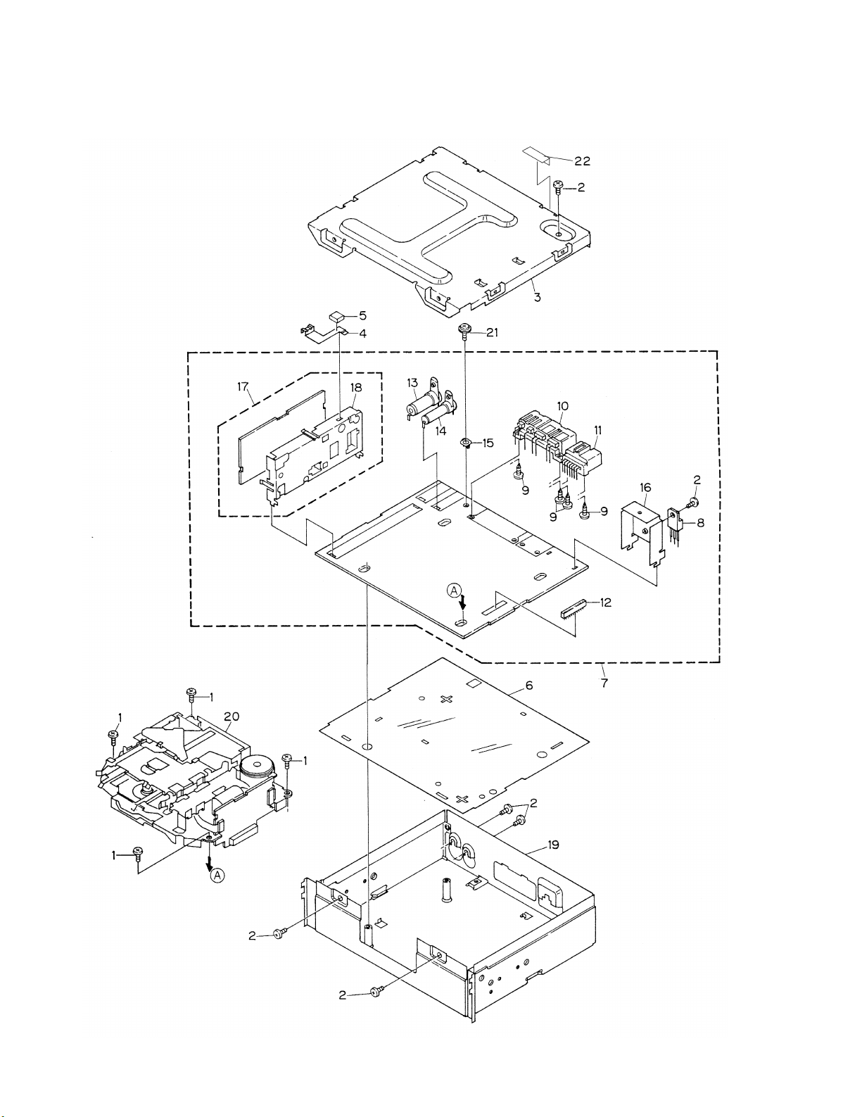
2. EXPLODED VIEWS AND PARTS LIST
2.1 EXTERIOR

5
KEX-M9086ZT,M9086ZT-91
- EXTERIOR SECTION PARTS LIST
NOTE:
- Parts marked by “*”are generally unavailable because they are not in our Master Spare Parts List.
- Screws adjacent to
∇ mark on the product are used for disassembly.
Mark No. Description Part No.
1 Screw BMZ26P050FMC
2 Screw BMZ30P060FMC
3 Case CNB2187
* 4 Earth CNC6739
5 Spacer CNM4305
6 Insulator CNM5314
7 Main Unit CWM5423
8 Transistor(Q813) 2SB1185
9 Screw CBA1393
10 Connector(CN801) CKM1222
11 Connector(CN802) CKM1238
12 Connector(CN702) CKS1730
13 Antenna Jack(CN501) CKX1057
14 Antenna Jack(CN502) CKX1058
15 Holder CNC2218
16 Holder CNC7149
17 Tuner Unit CWE1455
18 Holder CNC6774
19 Chassis Unit CXB1408
20
Cassette Mechanism ModuleEXK3240
21 Screw IMS30P050FMC
22 Nonwoven Fabric CNM5798
6
KEX-M9086ZT,M9086ZT-91
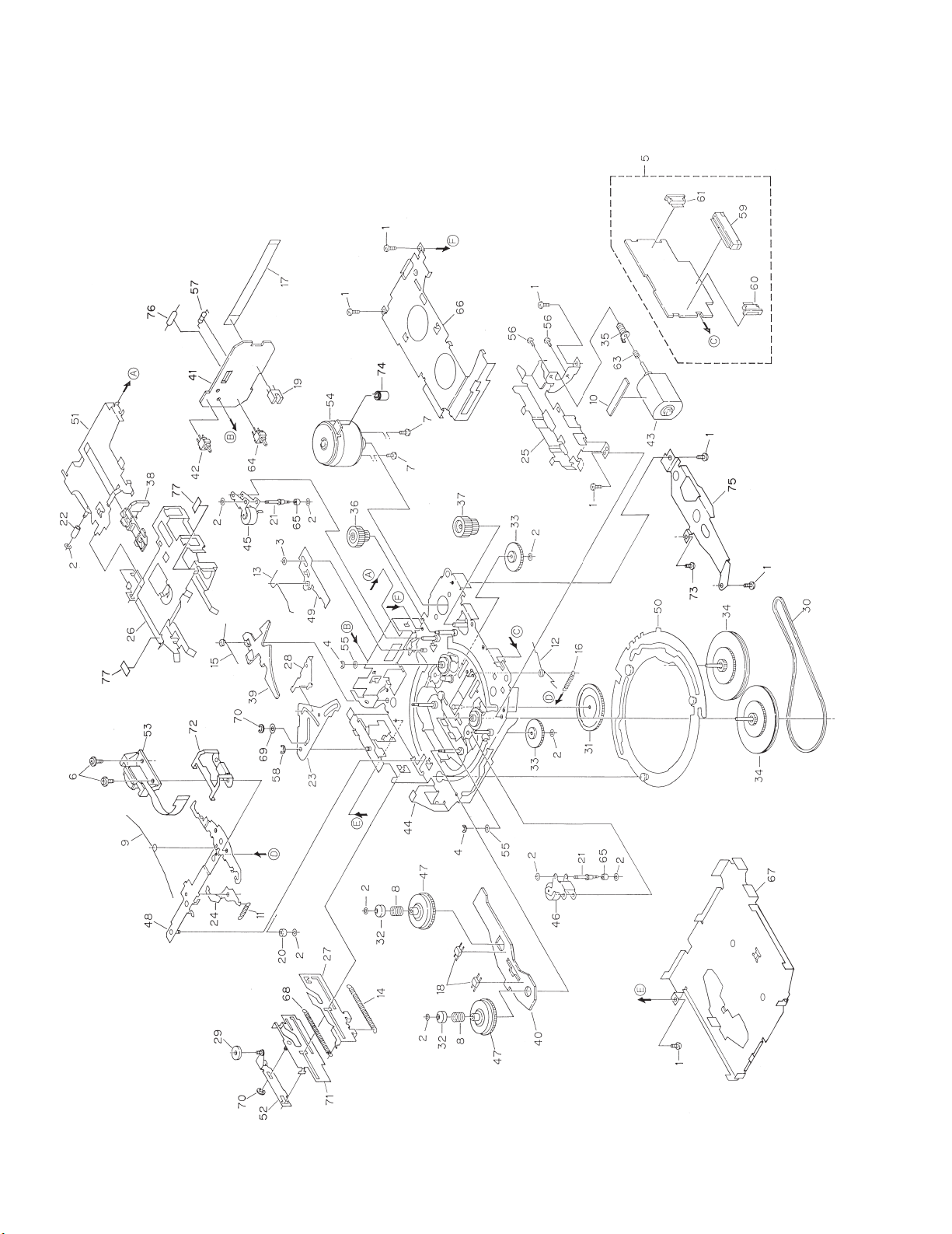
Fig. 2
2.2 CASSETTE MECHANISM MODULE

7
KEX-M9086ZT,M9086ZT-91
1 Screw BSZ20P040FMC
2 Washer CBF1037
3 Washer CBF1038
4 Washer CBG1003
5 Deck Unit EWM1008
6 Screw(M2×5) EBA1028
7 Screw(M2×2.5) EBA1037
8 Spring EBH1531
9 Spring EBH1589
10 Cushion ENM1034
11 Spring EBH1515
12 Spring EBH1587
13 Spring EBH1517
14 Spring EBH1547
15 Spring EBH1519
16 Spring EBH1537
17 Cord EDD1015
18 Photo-Reflector(EGN2, 3) EGN1004
19 Photo-Interrupter(EGN1) EGN1005
20 Roller ENR1031
21 Shaft ELA1362
22 Roller ELA1348
23 Arm ENC1416
24 Arm ENC1397
25 Guide ENC1398
26 Holder ENC1417
27 Lever ENC1449
28 Arm ENC1401
29 Roller ENR1027
30 Belt ENT1027
31 Gear ENV1347
32 Collar ENV1508
33 Gear ENV1350
34 Flywheel ENV1410
35 Worm Gear ENV1439
36 Worm Wheel ENV1440
37 Gear ENR1028
38 Lever ENV1455
39 Arm ENV1445
40 Gathering PCB ENX1029
41 Gathering PCB ENX1041
42 Switch(S1) ESG1004
43 Motor Unit(M2) EXA1485
44 Chassis Unit EXA1494
45 Pinch Roller Unit EXA1472
46 Pinch Roller Unit EXA1473
47 Reel Unit EXA1484
48 Head Base Unit EXA1434
49 Lever Unit EXA1438
50 Gear Unit EXA1436
51 Frame Unit EXA1476
52 Lever Unit EXA1425
53 Head Assy(HD1) EXA1481
54 Motor Unit(M1) EXA1497
55 Washer HBF-179
56 Screw BMZ20P022FMC
57 Resistor(R1) RD1/4HM181J
58 Washer YE20FUC
59 Connector(CN251) CKS1711
60 Connector(CN252) CKS2127
61 Connector(CN253) CKS2129
62 •••••
63 Spring EBH1545
64 Switch(S2) ESG1004
65 Roller ENR1023
66 Cover ENC1412
67 Cover ENC1413
68 Spring EBH1546
69 Washer EBE1008
70 Washer YE15FUC
71 Lever Unit EXA1424
72 Spring EBL1026
73 Screw(M2×2) CBA1250
74 Capacitor(C1) CEA4R7M35LS2
75 Bracket ENC1472
76 Inductor(L1) ETH0001
77 Cushion ENM1036
Mark No. Description Part No. Mark No. Description Part No.
- CASSETTE MECHANISM MODULE SECTION PARTS LIST
8
KEX-M9086ZT,M9086ZT-91
A
1
234
B
C
D
1
2
34
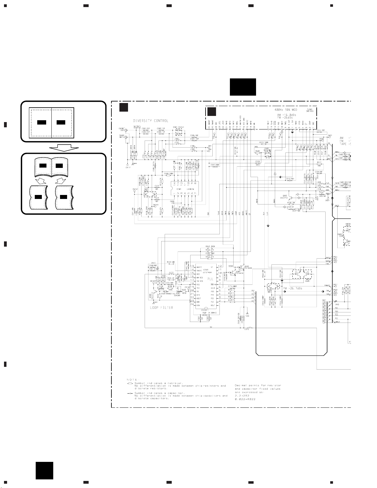
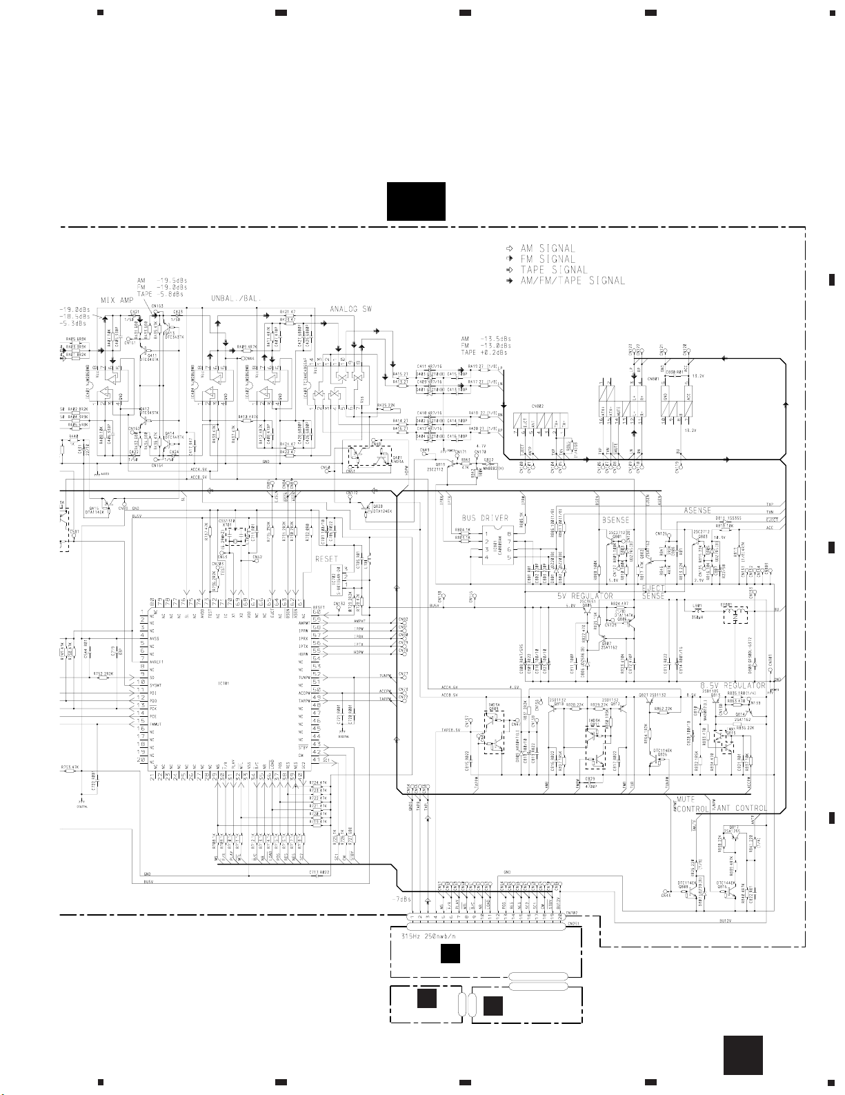
3. SCHEMATIC DIAGRAM
3.1 OVERALL CONNECTION DIAGRAM(GUIDE PAGE)
Note: When ordering service parts,be sure to refer to "EXPLODED VIEWS AND PARTS LIST"or"ELECTRICAL PARTS
LIST".
A
MAIN UNIT
TUNER UNIT
B
A-a
A
A-a A-b
A-a
A-b
A-b
A-a
Large size
SCH diagram
Guide page
Detailed page
9
KEX-M9086ZT,M9086ZT-91
5
6
7
8
A
B
C
D
5
6
7
8
Fig. 3
A-b
A
DECK UNIT
C
PCB UNIT
REEL PCB
D
E
PD4846B

10
KEX-M9086ZT,M9086ZT-91
A
1
234
B
C
D
1
2
34
A
MAIN UNIT
TUNER UNIT
B
A-a
A-b
A-a
11
KEX-M9086ZT,M9086ZT-91
5
6
7
8
A
B
C
D
5
6
7
8
A-a
A-b
Fig. 4
A-a
12
KEX-M9086ZT,M9086ZT-91
A
1
234
B
C
D
1
2
34
A-a
A-b
A-b
13
KEX-M9086ZT,M9086ZT-91
5
6
7
8
A
B
C
D
5
6
7
8
DECK UNIT
C
PCB UNIT
REEL PCB
D
E
PD4846B
A-a
A-b
Fig. 5
A-b

14
KEX-M9086ZT,M9086ZT-91
A
1
234
B
C
D
1
2
34
B
B
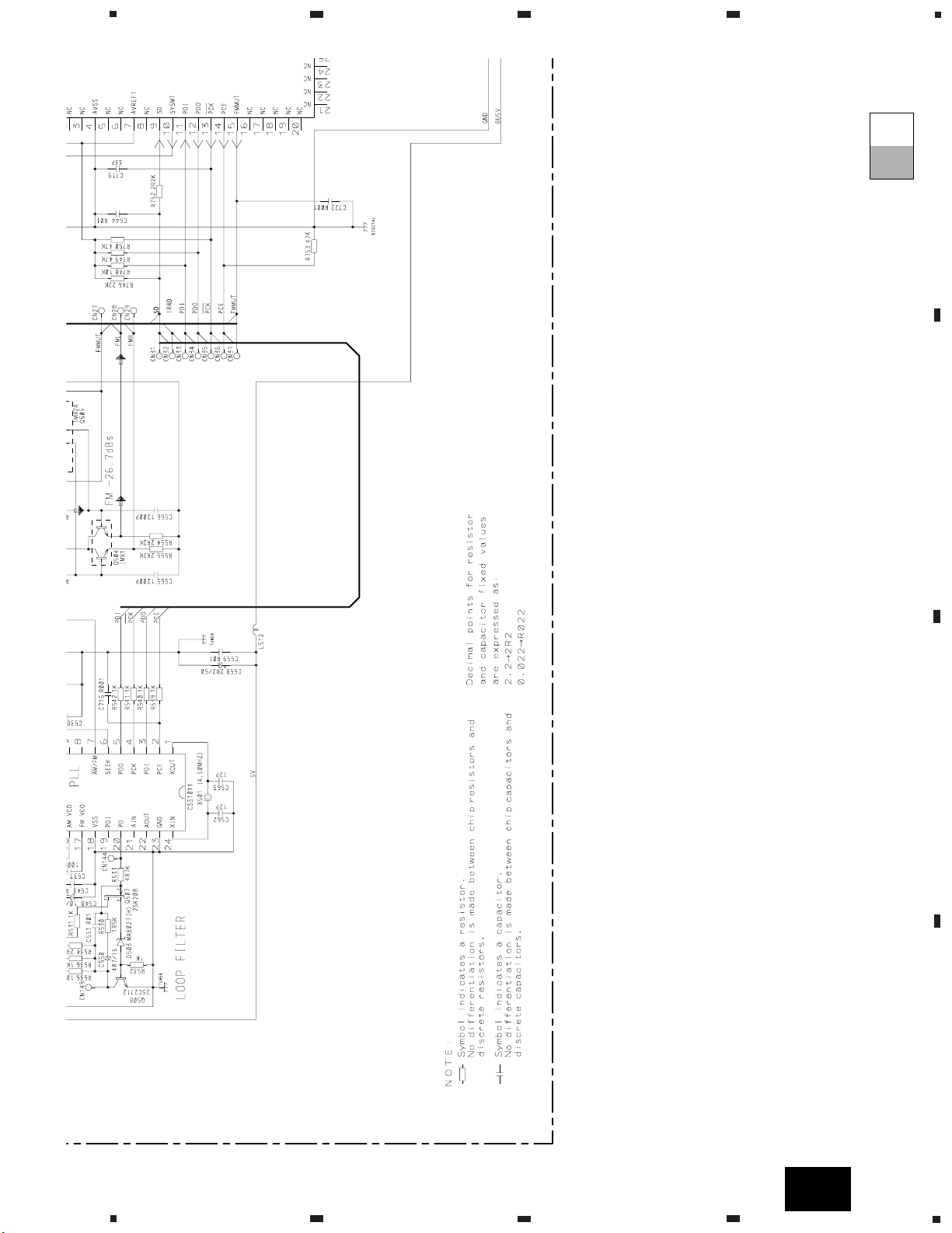
3.2 TUNER UNIT

15
KEX-M9086ZT,M9086ZT-91
5
6
7
8
A
B
C
D
5
6
7
8
I
B
Fig. 6
A

16
KEX-M9086ZT,M9086ZT-91
A
1
234
B
C
D
12
34
3.3 CASSETTE MECHANISM MODULE
C
A
D
C
CN702

17
KEX-M9086ZT,M9086ZT-91
5
6
7
8
A
B
C
D
5
6
7
8
E
F
E
D
C
Fig. 7
D
E


19
KEX-M9086ZT,M9086ZT-91
5
6
7
8
A
B
C
D
5
6
7
8
Fig. 8
SIDE A
CN251
C
A

20
KEX-M9086ZT,M9086ZT-91
A
1
234
B
C
D
1
2
34
A
MAIN UNIT
A

21
KEX-M9086ZT,M9086ZT-91
5
6
7
8
A
B
C
D
5
6
7
8
Fig. 9
SIDE B
A

22
KEX-M9086ZT,M9086ZT-91
A
1
234
B
C
D
12
34
B
4.2 TUNER UNIT
SIDE A
Fig. 10
B
TUNER UNIT
A

23
KEX-M9086ZT,M9086ZT-91
1
2
3
4
A
B
C
D
1
2
3
4
B
SIDE B
Fig. 11
B
TUNER UNIT

24
KEX-M9086ZT,M9086ZT-91
A
1
234
B
C
D
12
34
A
CN702
D
4.3 CASSETTE MECHANISM MODULE
Fig. 12
C
C
DECK UNIT

25
KEX-M9086ZT,M9086ZT-91
1
2
3
4
A
B
C
D
1
2
3
4
D
C
E
D
Fig. 13
Fig. 15
Fig. 14
E
D
REEL PCB
PCB UNIT
SIDE B
SIDE A
PCB UNIT
D
E

26
KEX-M9086ZT,M9086ZT-91
Unit Number: CWE1455
Unit Name : Tuner Unit
MISCELLANEOUS
IC 1 IC PA4026A
IC 2 IC PA4024A
Q 1 Transistor 2SC2712
Q 3 FET 3SK263
Q 5 Transistor 2SK1067
Q 31 Transistor 2SC2712
Q 151 Transistor DTC144EU
Q 201 FET 2SK291
Q 202 Transistor 2SC2712
D 3 Diode 1SV251
D 4 Diode 1SV250
D 5 Diode KV1410-F1
D 6 Diode MA157
D 7 Diode KV1410-F1
D 8 Diode KV1410-F1
D 9 Diode KV1410-F1
D 10 Diode 1SV250
D 201 Diode MA157
D 202 Diode 1SV251
D 231 Diode SVC253
L 1 Inductor LCTBR12K2125
L 2 Coil CTC1152
L 3 Coil CTC1152
L 4 Coil CTC1151
L 5 Coil CTC1147
L 6 Coil CTC1153
L 51 Ferri-Inductor LAU150K
L 52 Coil CTC1136
L 201 Ferri-Inductor LAU4R7K
L 202 Ferri-Inductor LAU330K
L 203 Inductor CTF1371
L 208 Inductor LAU390K
L 209 Ferri-Inductor LAU680K
L 210 Coil CTB1103
L 231 Inductor LAU3R3J
T 31 Coil CTE1116
TC 1 Capacitor CCL1038
TC 2 Capacitor CCL1038
TC 3 Capacitor CCL1038
CF 25 Ceramic Filter CTF1290
CF 51 Ceramic Filter CTF1290
CF 52 Ceramic Filter CTF1144
CF 53 Ceramic Filter CTF1145
CF 230 Crystal Filter CTF1262
CF 232 Ceramic Filter CTF1348
X 151 Resonator 918.5Hz CSS1365
X 231 Crystal Resonator 10.26MHz CSS1111
VR 101 Semi-fixed 15kΩ(B) CCP1230
VR 151 Semi-fixed 10kΩ(B) CCP1229
VR 154 Semi-fixed 150kΩ(B) CCP1236Ω
VR 156 Semi-fixed 100kΩ(B) CCP1235
RESISTORS
R 3 RS1/16S223J
R 4 RS1/16S101J
R 6 RS1/16S101J
R 8 RS1/16S332J
R 9 RS1/16S823J
R 10 RS1/16S223J
R 11 RS1/16S124J
R 12 RS1/16S474J
R 15 RS1/16S161J
R 16 RS1/16S104J
R 17 RS1/16S332J
R 18 RS1/16S332J
R 19 RS1/16S154J
R 21 RS1/16S332J
R 22 RS1/16S510J
R 24 RS1/16S101J
R 25 RS1/16S221J
R 26 RS1/16S102J
R 31 RS1/16S470J
R 32 RS1/16S912J
R 33 RS1/16S912J
R 34 RS1/16S331J
R 35 RS1/16S331J
R 51 RS1/16S331J
R 55 RS1/16S102J
R 56 RS1/16S823J
R 61 RS1/16S392J
R 62 RS1/16S273J
R 103 RS1/16S333J
R 104 RS1/16S334J
R 105 RS1/16S683J
R 107 RS1/16S222J
R 152 RS1/16S393J
R 155 RS1/16S393J
R 157 RS1/10S203J
R 160 RS1/16S222J
R 161 RS1/16S563J
R 162 RS1/16S225J
R 163 RS1/16S222J
R 164 RS1/16S823J
R 165 RS1/16S102J
R 201 RS1/16S103J
R 202 RS1/16S103J
R 203 RS1/16S225J
R 204 RS1/16S472J
R 205 RS1/16S471J
R 206 RS1/16S220J
R 207 RS1/16S101J
R 208 RS1/16S102J
R 214 RS1/16S183J
5. ELECTRICAL PARTS LIST
NOTE:
- Parts whose parts numbers are omitted are subject to being not supplied.
- The part numbers shown below indicate chip components.
Chip Resistor
RS1/_S___J,RS1/__S___J
Chip Capacitor (except for CQS.....)
CKS....., CCS....., CSZS.....
=====Circuit Symbol and No.===Part Name Part No.
--- ------ ------------------------------------------ -------------------------
=====Circuit Symbol and No.===Part Name Part No.
--- ------ ------------------------------------------ -------------------------
B

27
KEX-M9086ZT,M9086ZT-91
=====Circuit Symbol and No.===Part Name Part No.
--- ------ ------------------------------------------ -------------------------
=====Circuit Symbol and No.===Part Name Part No.
--- ------ ------------------------------------------ -------------------------
R 215 RS1/16S753J
R 230 RS1/16S0R0J
R 231 RS1/16S242J
R 232 RS1/16S473J
R 237 RS1/16S103J
R 238 RS1/16S104J
R 239 RS1/16S104J
R 240 RS1/16S103J
R 241 RS1/16S202J
R 243 RS1/16S123J
R 244 RS1/16S103J
R 246 RS1/16S0R0J
R 247 RS1/10S303J
R 248 RS1/16S0R0J
R 250 RS1/16S0R0J
CAPACITORS
C 1 CCSRCH220J50
C 2 CKSRYB222K50
C 3 CCSRCH4R0D50
C 5 CKSRYB222K50
C 6 CKSQYB473K16
C 7 CKSQYB473K16
C 8 CKSQYB104K16
C 9 CKSRYB222K50
C 10 CEJA1R0M50
C 11 CCSRCH470J50
C 12 CCSRCJ3R0C50
C 13 CKSRYB222K50
C 15 CCSRCJ3R0D50
C 17 CCSRCH120J50
C 18 CKSRYB103K25
C 19 CCSRCH120J50
C 20 CKSRYB222K50
C 21 CEJA100M16
C 22 CCSRRH100D50
C 23 CCSRRH150J50
C 24 CCSRCH471J50
C 30 CCSRRH201J50
C 31 CKSRYB103K25
C 32 CKSQYB473K16
C 33 CCSRCH220J50
C 34 CCSRCH4R0D50
C 40 CKSRYB222K50
C 41 CKSQYB104K16
C 51 CKSRYB223K25
C 52 CKSRYB103K25
C 54 CCSRCH470J50
C 55 CKSQYB223K25
C 56 CKSQYB104K16
C 57 CKSRYB472K50
C 58 CEJA330M10
C 59 CKSRYB103K25
C 61 CCSRCH270J50
C 62 CKSRYB103K25
C 63 CEJAR22M50
C 65 CKSQYB104K16
C 101 CEJANP100M10
C 102 CKSRYB182K50
C 103 CKSQYB682K50
C 104 CEJA2R2M50
C 105 CKSRYB103K25
C 106 CCSRCH151J50
C 107 CKSRYB103K25
C 151 CKSRYB562K25
C 152 CKSQYB104K16
C 153 CEJA3R3M50
C 154 CKSQYB104K16
C 157 CEJA3R3M50
C 158 CKSYB474K16
C 159 CEJA220M6R3
C 160 CKSQYB104K16
C 161 CKSQYB104K16
C 162 CEJA3R3M50
C 163 CKSRYB102K50
C 165 CCSRCH100D50
C 201 CKSRYB103K25
C 202 CCSRCH100D50
C 203 CKSRYB332K50
C 204 CKSQYB473K16
C 205 CKSQYB473K16
C 206 CKSRYB103K25
C 207 CCSRCH120J50
C 211 CCSRCH560J50
C 212 CEJA101M10
C 213 CKSRYB103K25
C 215 CCSRCH680J50
C 216 CCSRCH101J50
C 217 CEJA1R0M50
C 219 CKSRYB223K25
C 220 CKSRYB103K25
C 221 CKSRYB103K25
C 230 CKSQYB104K16
C 231 CCSRCH330J50
C 232 CCSRCH150J50
C 233 CKSRYB103K25
C 234 CEJA330M10
C 235 CKSRYB332K50
C 236 CKSQYB473K16
C 237 CCSRTH180J50
C 239 CKSRYB103K25
C 240 CKSYB104K16
C 241 CKSQYB104K16
C 242 CEJAR47M50
C 243 CKSQYB334K16
C 244 CKSQYB473K16
C 245 CKSQYB103K25
C 250 CCSRCJ3R0C50
Unit Number: EWM1008
Unit Name : Deck Unit
MISCELLANEOUS
IC 251 IC HA12173-01
IC 351 IC PA2020A
Q 271 Transistor 2SC4116
Q 351 Transistor 2SB1260
Q 352 Transistor 2SC4102
D 351 Diode MA141K
VR 301 Semi-fixed 33kΩ(B) CCP1130
VR 302 Semi-fixed 33kΩ(B) CCP1130
RESISTORS
R 255 RS1/16S181J
R 256 RS1/16S181J
R 257 RS1/16S183J
R 258 RS1/16S183J
R 259 RS1/16S133J
R 260 RS1/16S133J
R 261 RS1/16S274J
R 262 RS1/16S274J
R 271 RS1/16S183J
R 272 RS1/8S223J
C

28
KEX-M9086ZT,M9086ZT-91
R 273 RS1/8S223J
R 274 RS1/8S103J
R 275 RS1/16S473J
R 276 RS1/16S104J
R 277 RS1/16S224J
R 278 RS1/16S104J
R 281 RS1/8S0R0J
R 282 RS1/8S0R0J
R 283 RS1/8S0R0J
R 284 RS1/8S0R0J
R 285 RS1/16S0R0J
R 286 RS1/16S0R0J
R 287 RS1/16S0R0J
R 288 RS1/16S0R0J
R 289 RS1/16S0R0J
R 290 RS1/8S0R0J
R 301 RS1/16S223J
R 302 RS1/16S223J
R 303 RS1/16S561J
R 304 RS1/16S561J
R 321 RS1/8S223J
R 322 RS1/8S223J
R 351 RS1/16S102J
R 352 RS1/16S102J
R 353 RS1/16S102J
R 354 RS1/16S102J
R 355 RS1/10S274J
R 356 RS1/10S202J
R 357 RS1/10S472J
R 358 RS1/10S103J
R 359 RS1/10S103J
R 360 RS1/10S102J
R 361 RS1/10S622J
R 373 RS1/8S0R0J
R 374 RS1/8S0R0J
R 375 RS1/8S0R0J
R 401 RS1/16S273J
R 402 RS1/16S223J
R 403 RS1/16S274J
R 404 RS1/16S823J
R 405 RS1/16S274J
CAPACITORS
C 251 CKSRYB391K50
C 252 CKSRYB391K50
C 253 CKSRYB391K50
C 254 CKSRYB391K50
C 255 CKSRYB103K25
C 256 CKSRYB103K25
C 271 CEV1R0M50
C 272 CKSQYB104K16
C 301 CKSYB474K16
C 302 CKSYB474K16
C 303 CKSRYB222K50
C 304 CKSRYB222K50
C 305 CKSRYB222K50
C 306 CKSRYB222K50
C 307 CKSRYB222K50
C 308 CKSRYB222K50
C 309 CKSQYB104K16
C 310 CKSQYB104K16
C 311 CKSQYB104K16
C 312 CKSQYB104K16
C 322 CEV100M16
C 351 CKSYB224K25
C 352 CKSQYB392K50
C 353 CKSQYB103K50
C 354 CKSQYB103K50
C 355 CKSYB104K50
C 356 CKSQYB103K50
C 401 CKSRYB182K50
C 402 CKSRYB822K25
C 403 CKSRYB333K16
C 404 CKSRYB471K50
Unit Number: CWM5423
Unit Name : Main Unit
MISCELLANEOUS
IC 401 IC NJM2068MD
IC 402 IC NJM2068MD
IC 403 IC TC74HC4066AF
IC 404 IC NJM2068MD
IC 501 IC LA1061M
IC 503 IC LC72146M
IC 701 IC PD4846B
IC 702 IC S-80736AN-D0
IC 801 IC CA0008AM
Q 401 Transistor IMD3A
Q 411 Transistor DTC343TK
Q 412 Transistor DTC343TK
Q 413 Transistor DTC343TK
Q 414 Transistor DTC343TK
Q 415 Transistor DTA114EK
Q 501 Transistor IMX1
Q 502 Transistor 2SC2712
Q 503 Transistor DTC144EK
Q 504 Transistor IMX1
Q 505 Transistor IMH2A
Q 507 Transistor 2SK208
Q 508 Transistor 2SC2712
Q 509 Transistor DTC144EK
Q 801 Transistor 2SC2712
Q 802 Transistor 2SA1162
Q 803 Transistor 2SC2712
Q 805 Transistor 2SC3651
Q 806 Transistor DTA114TK
Q 807 Transistor 2SA1162
Q 808 Transistor DTC114EK
Q 809 Transistor IMD3A
Q 810 Transistor 2SB1132
Q 811 Transistor IMD3A
Q 812 Transistor 2SB1132
Q 813 Transistor 2SB1185
Q 814 Transistor 2SA1162
Q 815 Transistor IMX1
Q 816 Transistor DTC144EK
Q 817 Transistor 2SA1255
Q 818 Transistor 2SC2712
Q 819 Transistor IMD3A
Q 820 Transistor DTA124EK
Q 826 Transistor DTC114EK
Q 827 Transistor 2SB1132
D 401 Diode UDZ10(B)
D 402 Diode UDZ10(B)
D 403 Diode UDZ10(B)
D 404 Diode UDZ10(B)
D 501 Diode 1SV241
D 502 Chip Diode MA151WK
D 503 Diode MA8027(H)
D 801 Diode UDZ20(B)
D 802 Diode UDZ20(B)
D 803 Diode UDZ7R5(B)
D 805 Diode UDZ7R5(B)
=====Circuit Symbol and No.===Part Name Part No.
--- ------ ------------------------------------------ -------------------------
=====Circuit Symbol and No.===Part Name Part No.
--- ------ ------------------------------------------ -------------------------
A

29
KEX-M9086ZT,M9086ZT-91
D 806 Diode UDZ5R6(B)
D 807 Diode UDZ20(B)
D 808 Diode GP30DL-6372
D 809 Diode MA8047(L)
D 810 Diode MA8082(L)
D 811 Diode 1SS355
D 812 Diode MA8082(H)
L 501 Inductor LCTBR33K3216
L 502 Inductor LCTBR33K3216
L 503 Inductor LCTBR33K3216
L 504 Inductor LCTB4R7K3216
L 505 Inductor LCTB4R7K3216
L 506 Inductor LCTB1R0K2125
L 507 Inductor LCTA561J4532
L 508 Chip Inductor LCTA2R2J3225
L 509 Chip Inductor LCTA2R2J3225
L 510 Chip Inductor LCTA2R2J3225
L 512 Inductor LCTB2R2K3216
L 513 Coil LCTB150K3216
L 514 Inductor LCTBR33K3216
L 515 Inductor LCTBR33K3216
L 516 Inductor LCTBR33K3216
L 701 Inductor LCTB2R2K3216
L 702 Inductor LCTB2R2K3216
L 801 Coil 350µH CTH1092
X 501 Crystal Resonator 4.5MHz CSS1011
X 701 Ceramic Resonator 6.29MHz CSS1310
EF 801 EMI Filter CCG1006
AR 501 Arrester DSP-201M
AR 502 Arrester DSP-201M
Tuner Unit CWE1455
RESISTORS
R 401 RS1/10S822J
R 402 RS1/10S822J
R 403 RS1/10S392J
R 404 RS1/10S392J
R 405 RS1/10S682J
R 406 RS1/10S682J
R 407 RS1/10S103J
R 408 RS1/10S103J
R 409 RS1/10S472J
R 410 RS1/10S472J
R 411 RS1/10S472J
R 412 RS1/10S472J
R 413 RS1/10S270J
R 414 RS1/10S270J
R 415 RS1/10S270J
R 416 RS1/10S270J
R 417 RS1/8S270J
R 418 RS1/8S270J
R 419 RS1/8S270J
R 420 RS1/8S270J
R 421 RS1/10S470J
R 422 RS1/10S470J
R 423 RS1/10S470J
R 424 RS1/10S470J
R 425 RS1/10S223J
R 431 RS1/10S681J
R 432 RS1/10S681J
R 433 RS1/10S681J
R 434 RS1/10S681J
R 435 RS1/10S473J
R 436 RS1/10S473J
R 437 RS1/10S473J
R 438 RS1/10S473J
R 439 RS1/10S472J
R 440 RS1/10S102J
R 501 RS1/10S391J
R 502 RS1/10S471J
R 503 RS1/10S102J
R 504 RS1/10S104J
R 505 RS1/10S101J
R 506 RS1/10S101J
R 507 RS1/10S334J
R 508 RS1/10S224J
R 509 RS1/10S683J
R 510 RS1/10S182J
R 511 RS1/10S103J
R 512 RS1/10S473J
R 513 RS1/10S473J
R 514 RS1/10S104J
R 515 RS1/10S103J
R 516 RS1/10S103J
R 517 RS1/10S393J
R 518 RS1/10S103J
R 519 RS1/10S104J
R 520 RS1/10S272J
R 521 RS1/10S272J
R 522 RS1/10S473J
R 523 RS1/10S103J
R 530 RS1/10S152J
R 531 RS1/10S102J
R 532 RS1/10S102J
R 533 RS1/10S472J
R 534 RS1/10S222J
R 535 RS1/10S103J
R 536 RS1/10S102J
R 537 RS1/10S103J
R 538 RS1/10S103J
R 539 RS1/10S102J
R 540 RS1/10S102J
R 541 RS1/10S102J
R 542 RS1/10S102J
R 543 RS1/10S222J
R 552 RS1/10S103J
R 553 RS1/10S103J
R 554 RS1/10S222J
R 555 RS1/10S222J
R 561 RS1/10S123J
R 562 RS1/10S473J
R 563 RS1/10S332J
R 708 RS1/10S102J
R 709 RS1/10S102J
R 710 RS1/10S102J
R 711 RS1/10S102J
R 712 RS1/10S102J
R 713 RS1/10S102J
R 714 RS1/10S102J
R 715 RS1/10S102J
R 716 RS1/10S102J
R 717 RS1/10S102J
R 718 RS1/10S102J
R 719 RS1/10S473J
R 720 RS1/10S473J
R 721 RS1/10S473J
R 722 RS1/10S473J
R 723 RS1/10S473J
R 724 RS1/10S473J
R 725 RS1/10S102J
R 726 RS1/10S102J
R 727 RS1/10S681J
R 728 RS1/10S473J
=====Circuit Symbol and No.===Part Name Part No.
--- ------ ------------------------------------------ -------------------------
=====Circuit Symbol and No.===Part Name Part No.
--- ------ ------------------------------------------ -------------------------

30
KEX-M9086ZT,M9086ZT-91
=====Circuit Symbol and No.===Part Name Part No.
--- ------ ------------------------------------------ -------------------------
=====Circuit Symbol and No.===Part Name Part No.
--- ------ ------------------------------------------ -------------------------
R 729 RS1/10S222J
R 730 RS1/10S222J
R 731 RS1/10S222J
R 732 RS1/10S0R0J
R 736 RS1/10S222J
R 737 RS1/10S473J
R 746 RS1/10S223J
R 748 RS1/10S103J
R 749 RS1/10S473J
R 750 RS1/10S473J
R 752 RS1/10S222J
R 753 RS1/10S473J
R 776 RS1/10S222J
R 803 RS1/10S102J
R 804 RS1/10S102J
R 805 RS1/10S102J
R 806 RS1/8S101J
R 807 RS1/8S101J
R 808 RS1/10S104J
R 809 RS1/10S104J
R 810 RS1/10S104J
R 813 RS1/10S223J
R 815 RS1/10S223J
R 816 RS1/10S103J
R 817 RS1/10S473J
R 818 RS1/10S103J
R 819 RS1/8S472J
R 822 RS1/10S471J
R 823 RS1/10S474J
R 824 RS1/8S4R7J
R 825 RS1/10S153J
R 826 RS1/8S221J
R 827 RS1/10S152J
R 828 RS1/10S223J
R 829 RS1/10S223J
R 830 RS1/10S152J
R 831 RS1/10S222J
R 832 RS1/10S152J
R 833 RS1/10S471J
R 834 RS1/10S471J
R 835 RS1/4S1R0J
R 836 RS1/10S223J
R 837 RS1/10S103J
R 838 RS1/10S223J
R 839 RS1/10S472J
R 840 RS1/10S472J
R 841 RS1/4S221J
R 842 RS1/10S104J
R 843 RS1/10S473J
R 846 RS1/10S472J
R 847 RS1/10S222J
R 862 RS1/10S223J
R 863 RS1/10S471J
R 864 RS1/10S122J
R 865 RS1/4S680J
CAPACITORS
C 401 CEAL2R2M50
C 402 CEAL2R2M50
C 403 CEAL2R2M50
C 404 CEAL2R2M50
C 405 CCSQCH331J50
C 406 CCSQCH331J50
C 407 CCSQCH471J50
C 408 CCSQCH471J50
C 409 CEALNP4R7M16
C 410 CEALNP4R7M16
C 411 CEALNP4R7M16
C 412 CEALNP4R7M16
C 413 CCSQCH101J50
C 414 CCSQCH101J50
C 415 CCSQCH101J50
C 416 CCSQCH101J50
C 417 CKSQYB474K16
C 421 CEAL1R0M50
C 422 CEAL1R0M50
C 423 CEAL1R0M50
C 424 CEAL1R0M50
C 425 CKSQYB682K50
C 426 CKSQYB682K50
C 427 CKSQYB682K50
C 428 CKSQYB682K50
C 431 CEAL220M10
C 501 CCSQCH220J50
C 502 CCSQCH220J50
C 503 CCSQCH150J50
C 504 CCSQCH150J50
C 505 CKSQYB222K50
C 506 CKSQYB103K50
C 507 CCSQCH390J50
C 508 CEJA100M16
C 509 CEAL2R2M50
C 510 CKSQYB473K25
C 511 CKSQYB103K50
C 512 CKSQYB392K50
C 513 CKSQYB103K50
C 514 CKSQYB103K50
C 515 CKSQYB103K50
C 516 CEJA100M16
C 517 CKSQYB472K50
C 518 CKSQYB223K50
C 519 CKSQYB333K25
C 520 CKSQYB333K25
C 521 CEJA100M16
C 522 CEJA100M16
C 523 CEJA100M16
C 524 CEAL2R2M50
C 536 CKSQYB102K50
C 537 CCSQCH101J50
C 538 CKSQYB223K50
C 541 CKSQYB473K25
C 542 CCSQCH101J50
C 543 CKSQYB103K50
C 544 CKSQYB103K50
C 546 CKSQYB103K50
C 547 CKSQYB102K50
C 548 CEJA100M16
C 549 CKSQYB104K25
C 550 4.7µF/16V CCH1165
C 551 CKSQYB103K50
C 555 CKSQYB103K50
C 558 CEAL2R2M50
C 559 CKSQYB103K50
C 560 CGCYX103K25
C 561 CKSQYB472K50
C 562 CCSQCH120J50
C 563 CCSQCH120J50
C 564 CKSQYB103K50
C 565 CKSQYB122K50
C 566 CKSQYB122K50
C 570 CKSQYB562K50
C 705 CKSQYB103K50

31
KEX-M9086ZT,M9086ZT-91
=====Circuit Symbol and No.===Part Name Part No.
--- ------ ------------------------------------------ -------------------------
=====Circuit Symbol and No.===Part Name Part No.
--- ------ ------------------------------------------ -------------------------
C 706 CKSQYB223K50
C 707 CEAL101M10
C 711 CKSQYB103K50
C 716 CKSQYB102K50
C 717 CKSQYB223K50
C 719 CCSQCH330J50
C 720 CKSQYB102K50
C 721 CKSQYB102K50
C 722 CKSQYB102K50
C 801 CKSQYB103K50
C 802 CCSQCH221J50
C 803 CCSQCH221J50
C 806 CKSQYB103K50
C 807 CEALR22M50
C 808 0.047F/5.5V CCL1040
C 809 CKSQYB223K50
C 810 CEAL101M10
C 811 CCSQCH101J50
C 812 CCSQCH471J50
C 813 CKSQYB223K50
C 814 CEAS102M16
C 815 CKSQYB223K50
C 816 CKSQYB223K50
C 817 CKSQYB223K50
C 818 CEJA101M10
C 819 CKSQYB223K50
C 820 100µF/10V CCH1282
C 821 CKSQYB103K50
C 822 CKSQYB103K50
C 823 CEAL101M10
C 829 CKSQYB472K50
C 830 CKSYB103K50
Unit Number:
Unit Name : PCB Unit
L 1 Inductor ETH0001
S 1 Switch(Load) ESG1004
S 2 Switch(70µS) ESG1004
EGN 1 Photo-Interrupter EGN1005
R 1 RD1/4HM181J
Unit Number:
Unit Name : Reel PCB
EGN 2 Photo-Reflector EGN1004
EGN 3 Photo-Reflector EGN1004
Miscellaneous Parts List
M 1 Motor Unit(Main) EXA1497
M 2 Motor Unit(Sub) EXA1485
HD 1 Head Assy EXA1481
C 1 CEA4R7M35LS2
D
E


FM ADJUSTMENT
Modulation M:MONO MOD., 400Hz 30%(22.5kHz Dev.) or 400Hz 100%(75kHz Dev.)
S1:STEREO MOD., 1kHz, L or R=30%(20.25kHz+7.5kHz Dev.)
NOTE:Before proceeding to further adjustments after switching power ON, let the tuner run for ten minutes to allow
the circuits to stabilize.
FM SSG Displayed Adjustment Adjustment Method
No. Frequency(MHz) Level(dBf) Frequency(MHz) Point (Switch Position)
TUN Volt 1 ••••• ••••• 108.0 L5 DC V Meter(1) : 6V
Center 1 98.1 M 65-85 98.1 L52 Center Meter : 0
Meter
IFT 1 98.1 M 5-15 98.1 T31 mV Meter(1) : Maximum
ANT 1 98.1 M 5-15 98.1 TC1,TC2 mV Meter(1) : Maximum
Trimmer
RF Coil 1 89.9 M 5-15 89.9 L6 mV Meter(1) : Maximum
RF 1 106.1 M 5-15 106.1 TC3 mV Meter(1) : Maximum
Trimmer
Separation 1 98.1 S 65 98.1 VR101 mV Meter(1) : Maximum
ARC 1 98.1 S 40 98.1 VR154 mV Meter(1) : Separation 5dB
Separation
Interstation 1 98.1 M 65 98.1 – mV Meter(1) : AdB
Noise 2 98.1 M -∞ 98.1 VR151 mV Meter(1) : A-20dB
Search 1 98.1 M 33 98.1 VR156 DC V Meter(2) : more than 3.5V
Sensitivity 2 98.1 M 32 98.1 VR156 DC V Meter(2) : 0
3 Repeat steps 1 and 2 until the adjustment standards are satisfied.
DOLBY B/C NR ADJUSTMENT
No. Test Tape Adjustment Point Adjustment Method
(Switch Position)
1 NCT-150 VR301(Lch),VR302(Rch) mV Meter(2) : –8.24dBs+1.5dB,-0.5dB
(400Hz,200nwb/m) (DOLBY NR Switch : OFF)
34
KEX-M9086ZT,M9086ZT-91

35
KEX-M9086ZT,M9086ZT-91
7. GENERAL INFORMATION
7.1 IC
PA4026A
LA1061M

36
KEX-M9086ZT,M9086ZT-91
- Pin Functions (PD4846B)
Pin No. Pin Name I/O Format Function and Operation
1–3 NC Not used
4 AVSS A/D GND
5,6 NC Not used
7 AVREF1 (Connect to VDD)
8 NC Not used
9 SD I Station detector input
10 SYSMT O C System mute output
11 PDI I Data input from PLL IC
12 PDO O C Data output for PLL IC
13 pck O C Serial clock output for PLL IC
14 PCE O C Chip enable output for PLL IC
15 FMMUT O C FM mute output
16–28 NC Not used
29 MS I MS sense input
30 f/R O C Cassette mechanism head forward/reverse select output
31 PLAY O C Tape MS filter select output
32 mtl I 70µ tape detection input
33 VSS GND
34 b/C O C Cassette mechanism dolbyNR B/C select input
35 NR I Dolby NR ON/OFF select input
36 load I Loading detection input
37 POS I Position sense input
38 RES I Cassette mechanism reverse end sense input
39 NES I Cassette mechanism forward end sense input
40 SC2 O C Cassette mechanism sub motor control output
41 SC1 O C Cassette mechanism sub motor control output
42 CM O C Cassette mechanism capstan motor control output
43 stby O C Stand-by output
44–48 NC Not used
49 TAPPW O C Tape power
50 ACCPW O C ACC power output
51 NC Not used
52 TUNPW O C Tuner power control output
53,54 NC Not used
55 HDPW O C Analog switch control output
56 IPTX O C AVC-LAN driver data output
57 IPRX I AVC-LAN driver data input
58 IPPW O C Power supply control output for IP BUS interface IC
59 AMPMT O C Amprifier mute output
60 reset I Reset input
61 NC Not used
62 asen I ACC sense input
63 bsen I +B sense input
64 NC Not used
65 EJECT I Eject key input pin
66,67 NC Not used
68 VDD Power supply
69 X2 O Oscillator output
70 X1 I Oscillator input
71 IC Connect to GND
72 NC Not used
73 TEST I Test terminal input
74 AVDD A/D converter analog power supply (VDD)
75 NC Not used
76 SL I Signal level input
77–80 NC Not used

37
KEX-M9086ZT,M9086ZT-91
*PD4846B
IC's marked by* are MOS type.
Be careful in handling them because they are very
liable to be damaged by electrostatic induction.
Format Meaning
C C MOS
S-80736AN-D0
2 31
OUT VDD VSS
20
21
40
41
1
80
61
60

38
KEX-M9086ZT,M9086ZT-91
Normal
mode
System Check mode
The system runs a self-diagnosis and displays the
results (diagnostic codes).
•Max. 6 Diagnostic codes for each physical address (for
each connected device)
•Displays the current status (past errors not displayed)
Diagnosis Memory mode
The system displays historical operational errors
recorded for each physical address (for each device)
during normal operation in the past.
•Max. 6 Diagnostic codes for each physical address (for
each connected device)
LAN CHECK mode
The system displays the physical address of each
device connected to AVC-LAN.
•The device's own physical address is included.
Diagnosis Memory Clear
The system clears Diagnosis
Memory (the codes).
•After completing clearing, the
system goes to LAN CHECK mode.
6Memory Clear
Complete clearing
(automatic)
2End Diagnosis
3Go to System Check 4Return to LAN CHECK
5Go to Diagnosis Memory 4Return to LAN CHECK
2End Diagnosis
1Go to Diagnosis
2End Diagnosis
- Flowchart and Functions
- Operation Specifications
Integrated Panel (by Sumitomo Electric)
1Go to Diagnosis Press the CD key three times,
while holding down CH1 or CH6.
2End Diagnosis CD key (Press and hold for 1.7 seconds.)
ACC OFF/ON
3Go to System Check CH1
4Return to LAN CHECK CH8
5Go to Diagnosis Memory CH2
6Memory Clear CH5 (Press and hold for 1.7 seconds.)
•Page up TUNE +
•Page down TUNE -
7.2 DIAGNOSIS
7.2.1 DIAGNOSIS MODE

39
KEX-M9086ZT,M9086ZT-91
1 0123456789ABCDEF
1
3
2
Display
1—123
Serial No. Physical address
Example:2—190
The second device
connected is
an “audio H/U.”
1Device groups
1 : Controllers
2 : Video output devices
3 : Audio output devices
4 : Audio processing devices
5 : Information output devices
6 : Vehicle devices
- Physical Address Assignment
M.DISP
computer
AV
machine
1DIN
-TV
EMV Audio
ECU
Audio
H/U
Rear seatTV1DIN
navigation
Rear
controlSWIntegrate
-d Panel
CD-CH
commander
0
4
1-3
5-F
1 0123456789ABCDEF
2
Navigation
computer
ATIS FM
multiple
TV tuner CD-CH
with
video
0
1-F
1 0123456789ABCDEF
3
Radio Cassette
Radio/cas-
sette
without CH
controller
CD-P CD-CH MD-P MD-CH DAT DCC
TEL
ECU
0
8
1-7
9-F
1 0123456789ABCDEF
4
Equalizer
AMP
H. W
AMP
0
1-F
1 0123456789ABCDEF
5
GPS
receiver
ATIS
decoder
FM
multiplex
decoder
CD-CH
MD-CH
CD-ROM
-CH
MD-ROM
-CH
0
1-F
1 0123456789ABCDEF
6
A/C
computer
Body
computer
0
1-F
M-CD
decoder
LCD

40
KEX-M9086ZT,M9086ZT-91
1
2
- Assignment of Diagnostic Codes
Display
1– 12
Serial No. Diagnostic code
Example: 3–D2
The third content of Diagnosis is
"No response to periodical
communications."
NOTES:
*1 Instruction to check for an error
in periodical communications is
interrupted.
- Items corresponding each model
<During Diagnosis Memory mode>
• KEX-M9086ZT/UC
D1, D2, D4, FF, 50
<During System Check mode>
• KEX-M9086ZT/UC
No Diagnostic code assigned 00
Common Diagnostic code
among devices
Diagnostic code specific to a particular device Diagnostic code for
communications
NO
ERR
+B error
ACC
error
MUTE
error
Micropro-
cessor
error
ROM
error
RAM
error
AM tuner
error
FM tuner
error
TV tuner
error
Cassette
deck
error
Cassette
deck EJT
failure
Tape entan-
gled in the
cassette
deck
Dirt in
cassette
deck
head
Broken
cassette
deck belt
CD deck
or CD-CH
error
CD, CH
EJT
failure
Dirt, scar
and upside-
down in
CD, CH
Detected
P.U tem-
perature
in CD, CH
Detected
overcur-
rent in
CD, CH
CH
tray errorCHelevator
error
CD, CH
clamp
error
MD deck
or MD-CH
error
MD, CHrMD, CHrMD, CHrMD, CHrMD, CH
recording
function
error
CHrMD, CH
r
Amplifier
error
DSP
error
EQ error
LCD
error
Switch
error
Antenna
error
Main
antenna
error
Sub
antenna
errorTVantenna
error
Antenna
selector
error
AUDIO
ECU
error
No response
to commu-
nications
Commu-
nications
failure
No response
to periodical
communica-
tions
*1
No response
to Diagnosis
0123456789ABCDEF
0
1
2
3
4
5
6
7
8
9
A
B
C
D/E
F

41
KEX-M9086ZT,M9086ZT-91
LAN-CHECK mode System Check mode Diagnosis Memory mode
Beep
Display
• The system displays the physical address of each
device connected to AVC-LAN in sequence from
the lowest address.
Example: 1 — 1E0
Serial No. Physical address
(CD commander)
• When changing to another mode
Blinking "SYS" is displayed.
• After completing System Check
Displays a physical address.
••Identifies the device.
Example: H 150
Physical address (1DIN-TV)
Distinguishes from LAN-CHECK.
Displays a Diagnostic code.
••Identifies the type of error.
Example: 1 — d2
Serial No. Diagnostic code
(no response to periodical
communications)
Max. 6 for each physical address
Displays an auxiliary code
••Identifies the device involved in the error.
Example: 1 — 360
Serial No. Physical address (CD-CH)
1DIN-TV has recorded an error indicating there
is no response to periodical communications
in CD-CH.
1 — ———
When there is no physical address:
Displays a physical address.
The next lowest physical address
• When there is no Diagnostic code after completion
of System Check
00
The system changes as shown above, as this unit
does not include System Check.
• The system beeps three times
when changing to another mode.
• The system beeps once every time
a physical address is displayed.
• When changing to another mode
Blinking "CODE" is displayed.
• Then, "Latest periodical communications
number" is displayed.
••Elapsed time at the current point is displayed.
Example:
1F
Elapsed time (31 minutes)
• The system displays a number from 00 to
FF (increases a digit every minute).
• When 256 minutes are reached, the system
returns to 00.
• Displays the details of Diagnosis.
Displays a physical address.
(Same as the left.)
Displays a periodical communications
number.
••Displays the time when the error occurred.
Example: 1 — 02
Serial No. Elapsed time (2 minutes)
Displays Diagnostic code. (Same as the left.)
Displays an auxiliary code. (Same as the left.)
Displays a physical address.
• When there is no Diagnostic data:
00
• The system beeps three times
when changing to another mode.
• The system beeps once every time
a physical address is displayed.
• The system beeps three times
when starting up Diagnosis.
- Go to Diagnosis (Beep and Display)

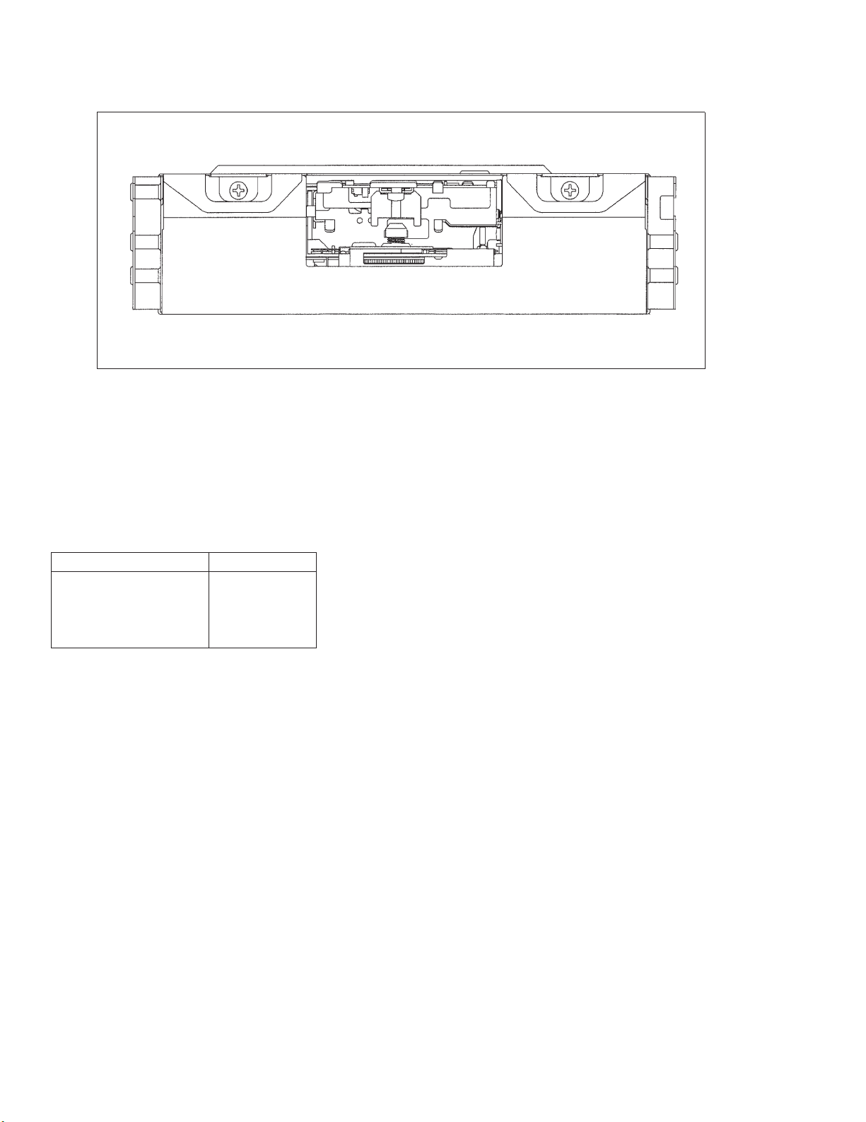
7.2.2 DISASSEMBLY
- Removing the Case(Fig.18)
1. Remove the three screws.
2. Remove the Case.
42
KEX-M9086ZT,M9086ZT-91
- Removing the Cassette Mechanism Module(not shown)
1. Remove the four screws.
2. Disconnect the connector.
3. Remove the Cassette Mechanism Module.
- Removing the Main Unit(Fig.19)
1. Remove the two screws A and the one screw B.
2. Straighten the hooks marked with arrows. While sliding the Main Unit forward, lift it up to remove.
Fig. 19
Fig. 18

43
KEX-M9086ZT,M9086ZT-91
ACC
B
GND
R+ L+
R-
L-
MUTE
ATX- ATX+
TX-
TX+
ANT
EJCT
Fig. 20
7.2.3 CONNECTOR FUNCTION DESCRIPTION

44
KEX-M9086ZT,M9086ZT-91
7.3 EXPLANATION
7.3.1 BLOCK DIAGRAM
Fig. 21
A
B
C
D
E

45
KEX-M9086ZT,M9086ZT-91
7.3.2 SYSTEM BLOCK DIAGRAM
Power Supply(+B, ACC)
BUS Signal
Audio Signal
CDX-M9086ZT/UC
CDX-M9186ZT/UC
Vehicle
Fig. 22
DISPLAY
HEAD UNIT
POWER
AMPLIFIER
INTEGRATED
PANEL
DISC PLAYER
ASSY
KEX-M9086ZT/UC GM-9086ZT/UC

KEX-M9086ZT,M9086ZT-91
8. OPERATIONS AND SPECIFICATIONS
8.1 SPECIFICATIONS
General
Power source...................13.2 V(10.5V—16.0V allowable)
Grounding system...............................Negative type
Weight ......................................1.125 kg (± 0.6 kg)
Tape player
Tape.......................Compact cassette tape (C-30—C-90)
Tape speed ...........4.76 cm/sec.(+0.14 cm/sec.,-0.05 cm/sec.)
Wow & flutter ..........................less than 0.2 %(WRMS)
Crosstalk .....................................more than 40 dB
Stereo separation .............................more than 30 dB
Signal-to-noise ratio ..........................more than 45 dB
FM tuner
Frequency range ............................87.7 — 107.9 MHz
Usable sensitivity .....................7 dBµ±6dB (S/N: 30 dB)
Signal-to-noise ratio .................more than 50 dB (55 dBµ)
Distortion .......................................less than 1.5%
Stereo separation ..........more than 25 dB (1 kHz : 35 ± 10dB)
MW tuner
Frequency range ..............................530 — 1,710 kHz
Usable sensitivity ....................27 dBµ±5dB (S/N: 20 dB)
Signal-to-noise ratio...................more than 44 dB(74dBµ)
Distortion .......................................less than 1.0%
PIONEER ELECTRONIC CORPORATION 4-1, Meguro 1-Chome, Meguro-ku, Tokyo 153, Japan
PIONEER ELECTRONICS SERVICE INC. P.O.Box 1760, Long Beach, CA 90801-1760 U.S.A.
PIONEER ELECTRONIC [EUROPE] N.V. Haven 1087 Keetberglaan 1, 9120 Melsele, Belgium
PIONEER ELECTRONICS ASIACENTRE PTE.LTD. 501 Orchard Road, #10-00, Wheelock Place, Singapore 238880
C PIONEER ELECTRONIC CORPORATION 1997
K-ZEB. DEC. 1997 Printed in Japan
 Loading...