

Page 1
ORDER NO.
CRT2732
PUB. NO. CRT2732
AUDIO SYSTEM
HEAD UNIT
Manufactured for TOYOTA
by PIONEER CORPORATION
VEHICLE DESTINATION PRODUCED AFTER TOYOTA PART No. ID No. PIONEER MODEL No.
LEXUS RX300 Middle Near East August 2001 86120-48140 P2727 KEX-M8017ZT/ES
LEXUS RX300 Middle Near East August 2001 86120-48140 P2727 KEX-M8017ZT-91/ES
RX300
Page 2
2
KEX-M8017ZT,M8017ZT-91
- Dolby noise reduction manufactured under license from Dolby Laboratories Licensing Corporation.
"Dolby" and the double-D symbol are trademarks of Dolby Laboratories Licensing Corporation.
- This service manual does not describe the CD test mode.
For the operations in the CD test mode, refer to the CD player's Service Manual.
- KEX-M8017ZT/ES have adopted AVC-LAN.
KEX-M8017ZT/ES
CONTENTS
1. SAFETY INFORMATION ............................................3
2. EXPLODED VIEWS AND PARTS LIST.......................4
3. BLOCK DIAGRAM AND SCHEMATIC DIAGRAM.....8
4. PCB CONNECTION DIAGRAM ................................20
5. ELECTRICAL PARTS LIST ........................................28
6. ADJUSTMENT..........................................................34
7. GENERAL INFORMATION .......................................38
7.1 DIAGNOSIS.......................................................38
7.1.1 CONNECTOR FUNCTION DESCRIPTION ..38
7.1.2 TROUBLESHOOTING................................39
7.2 IC........................................................................40
7.3 EXPLANATION..................................................43
7.3.1 SYSTEM BLOCK DIAGRAM ...................43
7.3.2 OPERATION FLOW CHART.....................44
8. SPECIFICATIONS......................................................45
- Supplementary model is identical to the original except for the addition of following items.
Description Part No.
KEX-M8017ZT-91/ES
Polyethylene Bag CEG-162
Cover CEG1045
Carton CHA1721
Contain Box CHL3223
ID No.P2727
- This service manual should be used together with the following manual(s):
Model Order No. Mech. Module Remarks
CX-631 CRT1640 2L Cassette Mech. Module:Mech.Description, Disassembly
Page 3

3
KEX-M8017ZT,M8017ZT-91
1. SAFETY INFORMATION
This service manual is intended for qualified service technicians; it is not meant for the casual do-it-yourselfer.
Qualified technicians have the necessary test equipment and tools, and have been trained to properly and safely repair
complex products such as those covered by this manual.
Improperly performed repairs can adversely affect the safety and reliability of the product and may void the warranty.
If you are not qualified to perform the repair of this product properly and safely, you should not risk trying to do so
and refer the repair to a qualified service technician.
Page 4
4
KEX-M8017ZT,M8017ZT-91
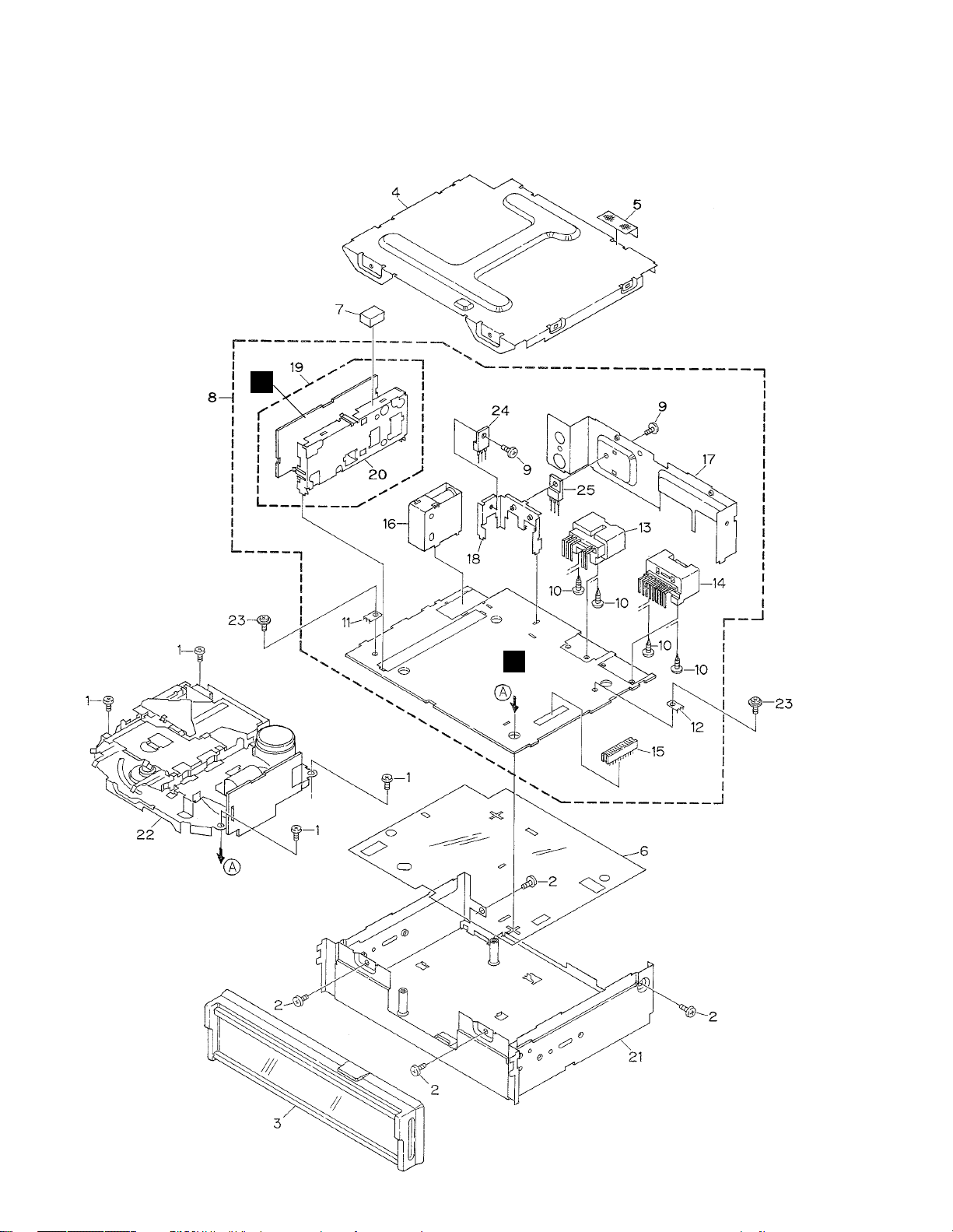
2. EXPLODED VIEWS AND PARTS LIST
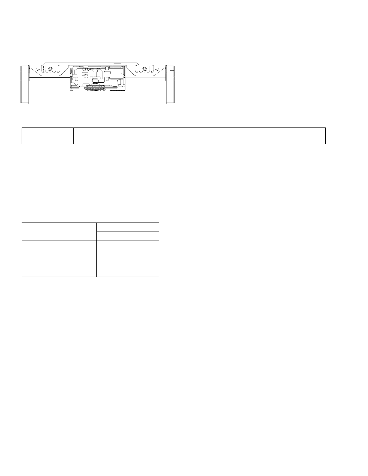
2.1 EXTERIOR
B
A
Page 5

5
KEX-M8017ZT,M8017ZT-91
- EXTERIOR SECTION PARTS LIST
Mark No. Description Part No.
1 Screw BMZ26P050FMC
2 Screw BMZ30P050FMC
3 Cover(KEX-M8017ZT/ES) CHW1830
4 Case CNB2621
5 Cloth CNM5798
6 Insulator CNM6654
7 Cushion CNM6934
8 Main Unit CWM7852
9 Screw BMZ30P080FMC
10 Screw BPZ30P060FSN
11 Terminal(CN202) CKF1059
12 Terminal(CN303) CKF1059
13 Connector(CN302) CKM1065
14 Connector(CN301) CKM1322
15 Connector(CN701) CKS3568
16 Antenna Jack(CN201) CKX1041
17 Holder CNC8711
18 Holder CNC8712
19 FM/AM Tuner Unit CWE1544
20 Holder CNC6122
21 Chassis Unit CXB5302
22
Cassette Mechanism ModuleEXK3885
23 Screw IMS26P050FMC
24 Transistor(Q331) 2SB1185
25 Transistor(Q521) 2SB1185
NOTE:
- Parts marked by “*” are generally unavailable because they are not in our Master Spare Parts List.
- Screws adjacent to ∇ mark on the product are used for disassembly.
Page 6
6
KEX-M8017ZT,M8017ZT-91
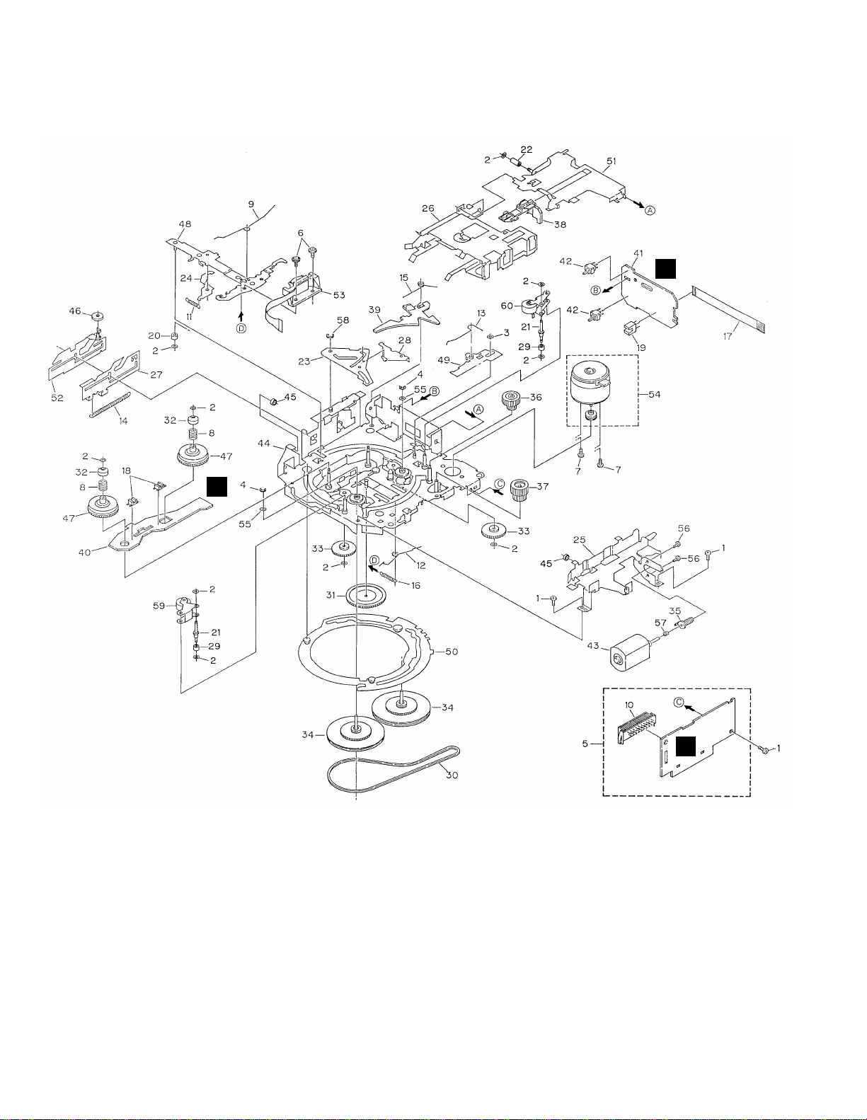
2.2 CASSETTE MECHANISM MODULE
C
E
D
Page 7

7
KEX-M8017ZT,M8017ZT-91
1 Screw BSZ20P040FMC
2 Washer CBF1037
3 Washer CBF1038
4 Washer CBG1003
5 Deck Unit EWM1027
6 Screw(M2x5) EBA1028
7 Screw(M2x2.5) EBA1037
8 Spring EBH1531
9 Spring EBH1589
10 Connector(CN251) CKS3540
11 Spring EBH1515
12 Spring EBH1587
13 Spring EBH1517
14 Spring EBH1518
15 Spring EBH1519
16 Spring EBH1537
17 Cord EDD1027
18 Photo-interrupter
(EGN2,3) EGN1006
19 Photo-interrupter(EGN1) EGN1005
20 Roller ENR1031
21 Shaft ELA1362
22 Roller ELA1348
23 Arm ENC1490
24 Arm ENC1397
25 Guide ENC1519
26 Holder ENC1516
27 Lever ENC1448
28 Arm ENC1488
29 Roller ENR1023
30 Belt ENT1027
31 Gear ENV1347
32 Collar ENV1508
33 Gear ENV1350
34 Flywheel ENV1500
35 Worm Gear ENV1439
36 Worm Wheel ENV1440
37 Gear ENR1037
38 Lever ENV1533
39 Arm ENV1525
40 PCB ENP1151
41 PCB ENP1182
42 Switch(S1)(S2) ESG1004
43 Motor Unit(M2)(SUB) EXA1382
44 Chassis Unit EXA1559
45 Tube ENM1039
46 Roller ENR1027
47 Reel Unit EXA1560
48 Head Base Unit EXA1434
49 Lever Unit EXA1578
50 Gear Unit EXA1545
51 Frame Unit EXA1476
52 Lever Unit EXA1439
53 Head Assy(HD1) EXA1594
54 Motor Unit(M1)(MAIN) EXA1499
55 Washer HBF-179
56 Screw JGZ20P025FNI
57 Spring EBH1545
58 Washer YE20FUC
59 Pinch Roller Unit EXA1533
60 Pinch Roller Unit EXA1532
Mark No. Description Part No. Mark No. Description Part No.
- CASSETTE MECHANISM MODULE SECTION PARTS LIST
Page 8
8
KEX-M8017ZT,M8017ZT-91
A
1
234
B
C
D
12
34
Q3
L2 D5
L4 D7
25
26
Q201
AM RF
AM
OSC
FM
OSC
D231
CF52
CF51
T31
Q31
CF232
CF230
23
25
PA4026A
IC1
CF53
L52
PA4024A
IC2
AM
CN201
ANT
FMTV
AMTV
VCO
AMIFC
FMB
AMB
TUNB
19 20
17
15 21
14
13
6
2
IC201
PM2006A
PLL
XIN
XOUT
PDI
PCK
PDO
PCE
29
25
9
5
4
CN251
CN252
CN253
IC251
HA12216F
TAPE EQUALIZER
MECHANISM DRIVER
IC351
PA2020A
Q271
B.U
BU
M
SUB
MOTOR
M
MAIN
MOTOR
10
+B
TAPE-L
MTL
MTL
VR301
VREF
6
22
14
17
2
51
53
17
7
18
19
5
2
NR
Q351
Q352
1
9
8
STBY
LOAD
LOAD
SWITCH
MODE
SENSE
FWD
SENSE
REV
SENSE
1
4
5
4
3
20
FWD
LcH
REV
LcH
23
8
1
64
23
8
1
64
41
910
34
63836
32
14 15 17 19
30
31
28
47
1
2
19
40 7
43
Lch
FMSL
AMSL
AMIF
ST
COMP
FMSD
S-80736AN-D0
IC703
2
1
RESET
VDD
AM-L
M
M
FM-L
AM-L
BU
CN701
4
3
20
13
15
12
RESET
Q706
88
TAPEMUTE
AUD+B
TAPE-L
SL
XIN
XOUT
S
PDI
PCK
PDO
PCE
ST
SD
38
37
A
MAIN UNIT
FM/AM TUNER UNIT
B
C
DECK UNIT
D
PCB UNIT
E
REEL PCB
7
9
18
10
3
SWITCH
70µs
Q231
Q205
Q206
Q204
28
27
MW/sw
sw!/SW2 sw!/SW2
2
sw!/SW2
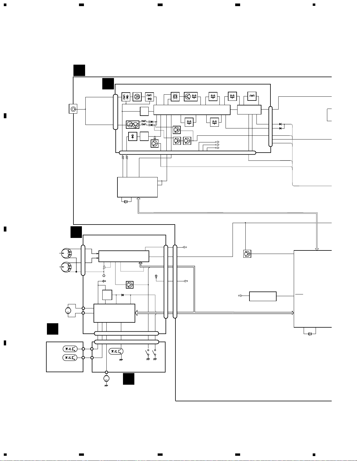
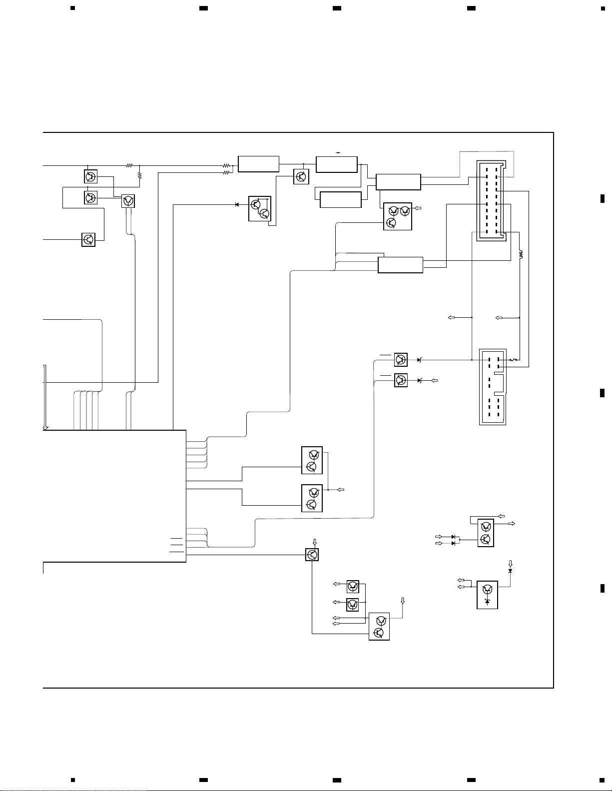
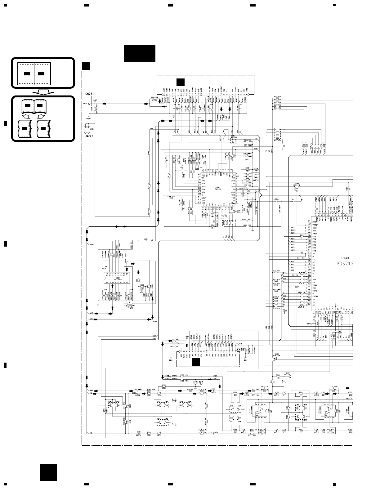
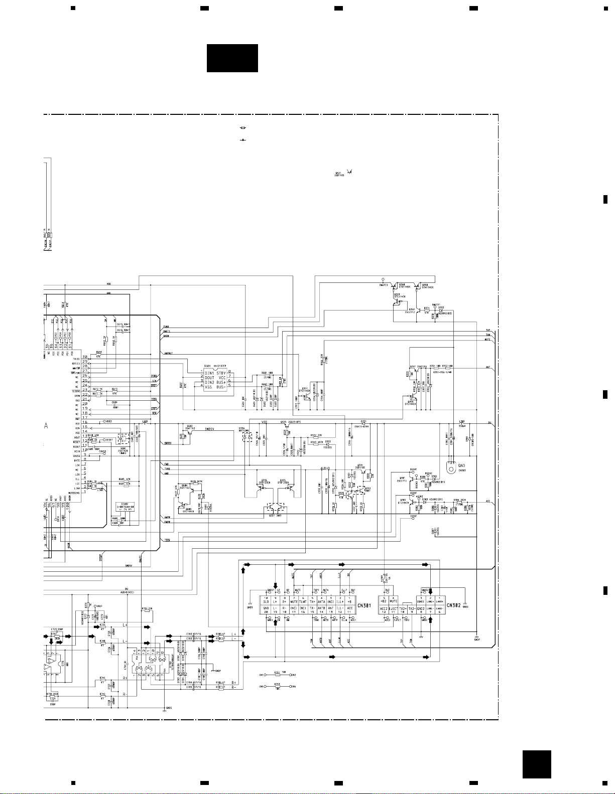
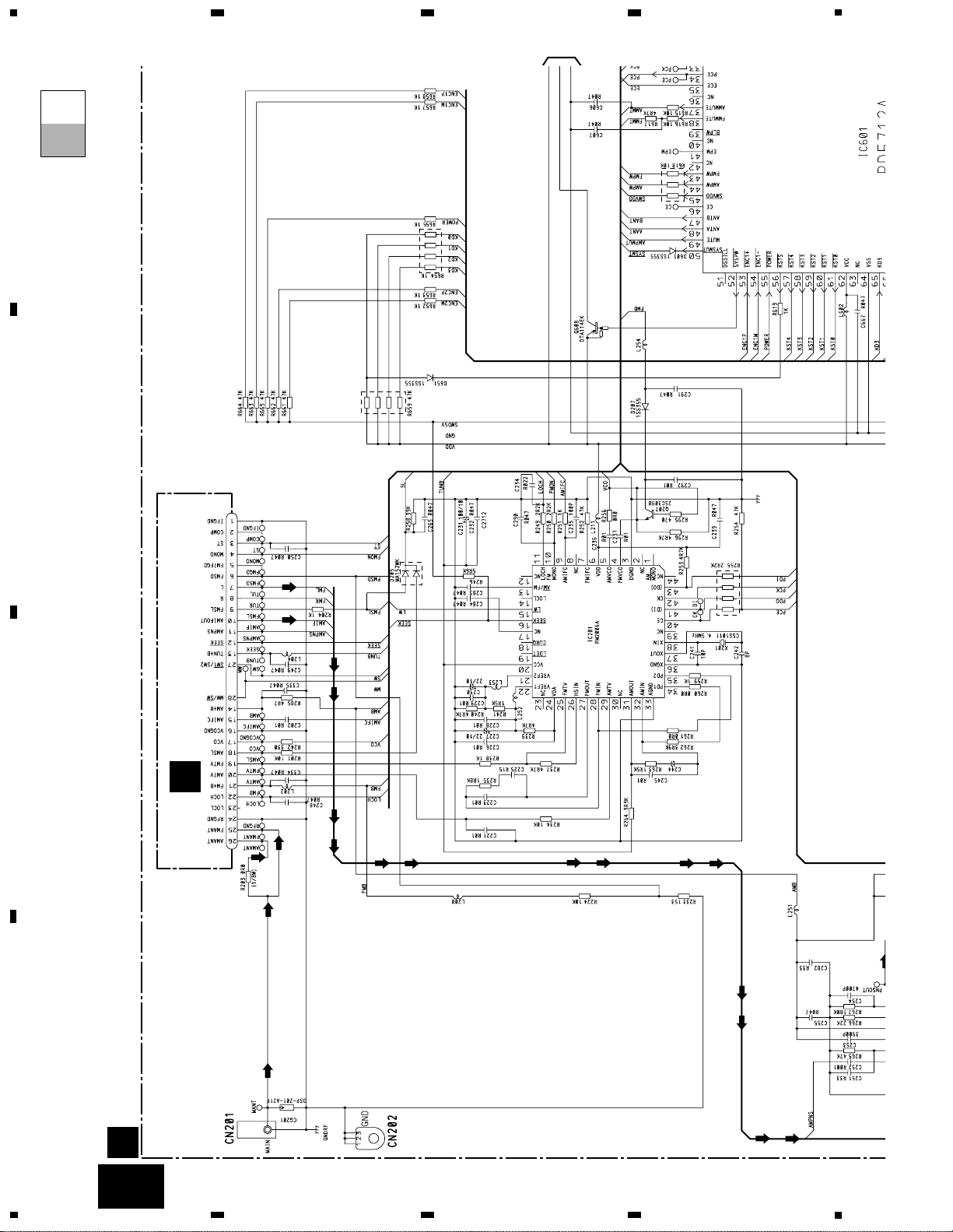
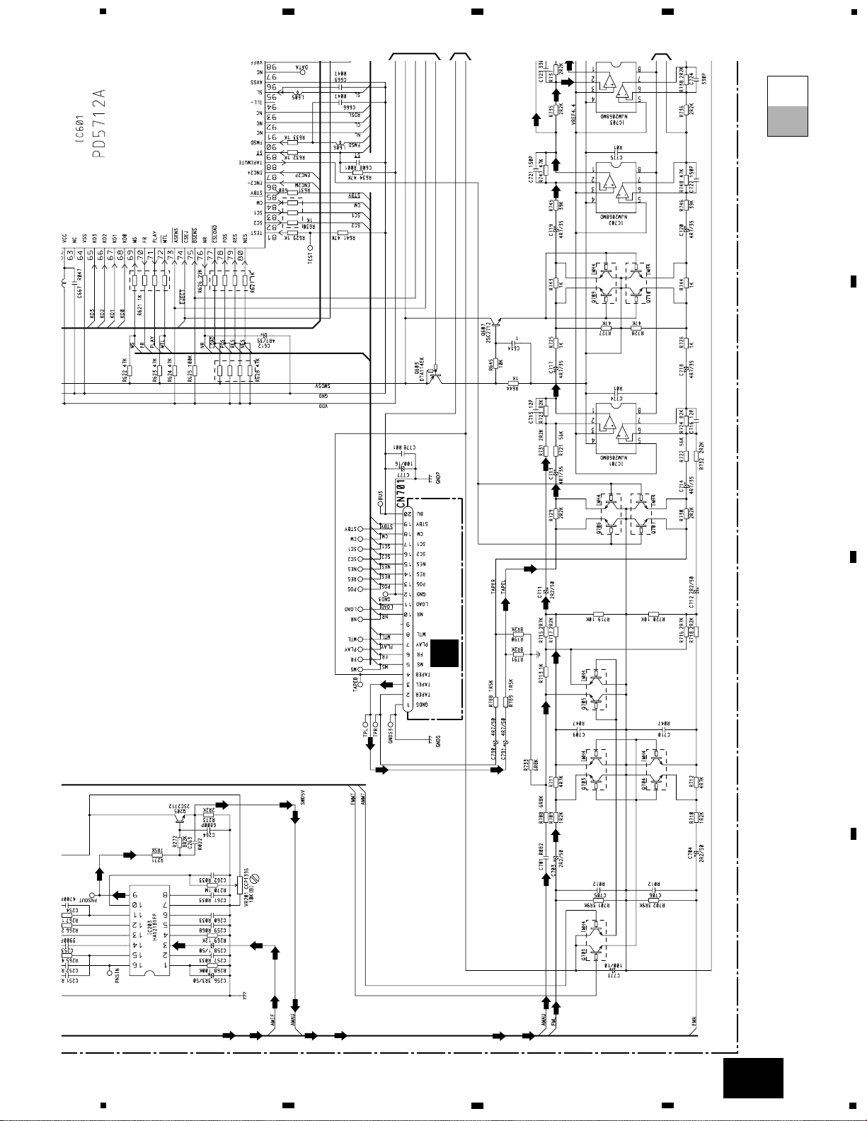
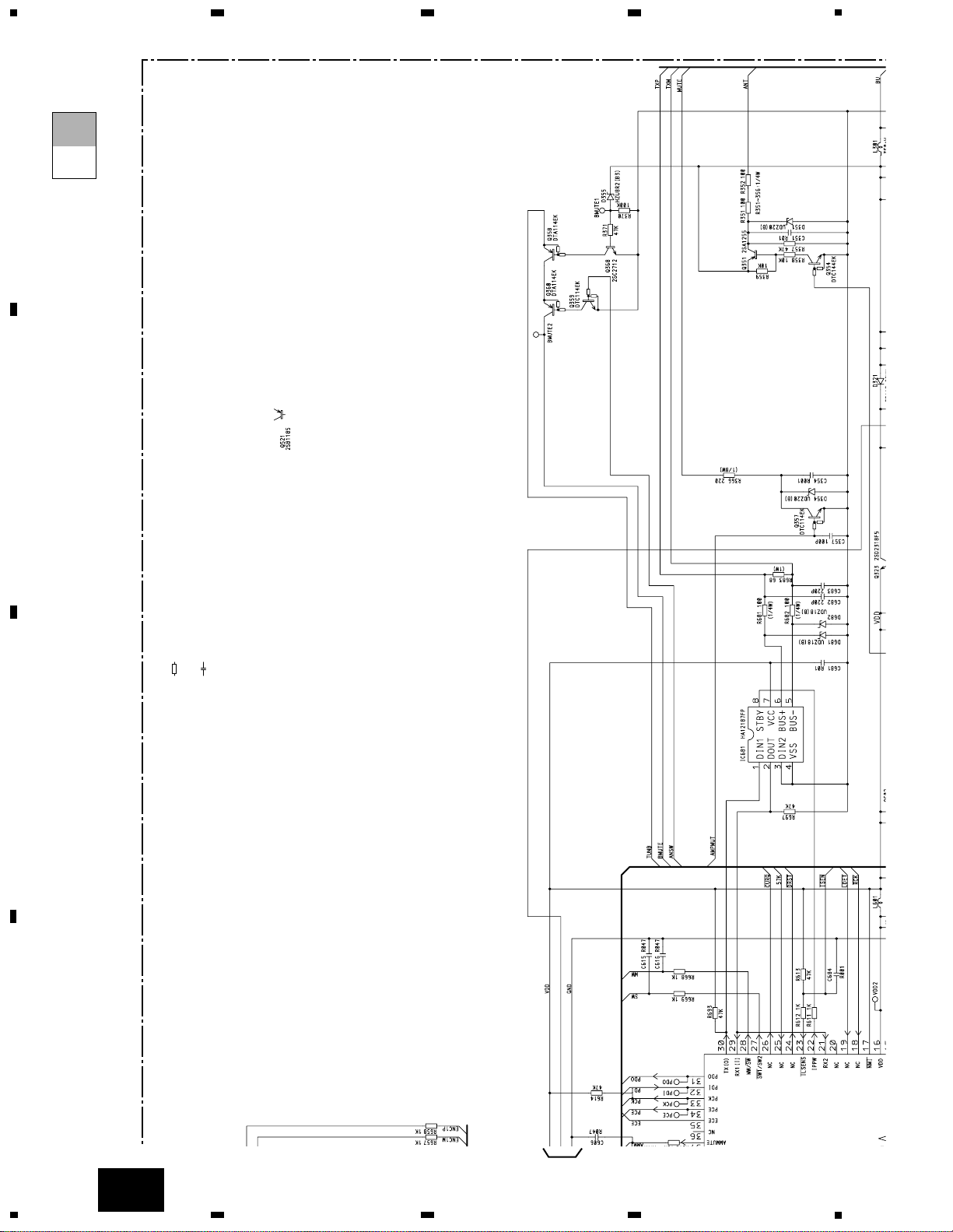
3. BLOCK DIAGRAM AND SCHEMATIC DIAGRAM
3.1 BLOCK DIAGRAM
Page 9
9
KEX-M8017ZT,M8017ZT-91
5
6
7
8
A
B
C
D
5
6
7
8
BU
Q323
5V
REGULATOR
VDD5V
VDD
Q332
Q331
AUD+B
TUNB
BU
8V
REGULATOR
Q608
VDD SWITCH
VDD
SYSPW
Q337-1
Q336
Q337-2
Q335
Q302
ASEN
Q301
BSEN
BU
Q359
Q360
Q358
TUNB
AUD+B
TC74HC4066AF
IC781
ANALOG
SWITCH
NJM2068MD
IC703
NJM2068MD
IC702
Q709
Q603
Q607
UNBAL BAL
NJM2068MD
MIX AMP
IC701
10
8
L+
L-
11
9
6,12
ANSW
Q205
Q703
MUTE
Q705
MUTE
Q701
AM-L
TUNER-L
2
1
2
1
2
1
Q354
Q351
AMB
FMB
BU
ANT
TAPE-L
AMMT
FMMT
AMMT
FMMT
37
38
XIN
SYSTEM CONTROLLER
IC601
PDI
SL
SD
95
90
ST
89
AMPW
AMPW
44
FMPW
43
AUD+B
73
75
ASEN
BSEN
HA12187FP
IC681
AVC LAN
6
5
TX+
TX-
50
SYSMUTE
IPPW
8
1
2
TX
RX
MUTESENS
RX
TX
IPPW
ANSW
22
30
29
1
100
CN301
CN302
BU
ACC
48
AANT
47
BANT
MUTE
+B
ACC
FMPW
AMB
FMB
Q335
Q336
PD5712A
52
SYSPW
2827
MW/sw
sw!/SW2
Page 10
10
KEX-M8017ZT,M8017ZT-91
A
1
234
B
C
D
12
34
3.2 MAIN UNIT(GUIDE PAGE)
Note: When ordering service parts, be sure to refer to “EXPLODED VIEWS AND PARTS LIST” or “ELECTRICAL PARTS
LIST”.
A
B
FM/AM TUNER UNIT
A
MAIN UNIT
C
DECK UNIT
4R7/10
AM
FM
AM
FM
AM
FM
AM
FM
AM
FM
AM
FM
AM
FM
AM
FM
AM
FM
AM
AM
AM AM
AM
AM
AM
AM AM
AM
AM
AM
FM
AM
FM
FM
FM
FM
AM AM
AM
SYSTEM
CONTROLLER
UNBALANCE
CONVERTER
SYSTEM MUTE
MIX AMP
TAPE MUTE
TUNER MUTE
PLL
FM:-26dBs(400Hz,30%)
AM:-16dBs(400Hz,30%)
TAPE:- 8dBs
ANTENNA JACK
A-a
A-aA-a A-b A-b
A-aA-a
A-b A-b
A-b A-b
A-a A-a
Large size
SCH diagram
Guide page
Detailed page
Page 11
11
KEX-M8017ZT,M8017ZT-91
5
6
7
8
A
B
C
D
5
6
7
8
A
Decimal points for resistor
and capacitor fixed values
are expressed as :
2.2 2R2
0.022 R022
←
←
The > mark found on some component parts indicates
the importance of the safety factor of the part.
Therefore, when replacing, be sure to use parts of
identical designation.
Symbol indicates a resistor.
No differentiation is made between chip resistors and
discrete resistors.
NOTE :
Symbol indicates a capacitor.
No differentiation is made between chip capacitors and
discrete capacitors.
>
AVC LAN
MUTE
5V REGULATOR
AUDIO 8V REGULATOR
RESET
ANALOG SWITCH
AUDIO 4V
TO BALANCE
FM:-18dBs
AM:-18dBs
TAPE:-4dBs
FM:-13dBs
AM:-13dBs
TAPE:+1dBs
A-b
Page 12
12
KEX-M8017ZT,M8017ZT-91
A
1
234
B
C
D
12
34
A-a
A-a
A-b
B
FM/AM TUNER UNIT
A
MAIN UNIT
4R7/10
AM
FM
AM
FM
AM
FM
AM
FM
AM
FM
AM
FM
AM
FM
AM
FM
AM
PLL
FM:-26dBs(400Hz,30%)
AM:-16dBs(400Hz,30%)
ANTENNA JACK
1
Page 13
13
KEX-M8017ZT,M8017ZT-91
5
6
7
8
A
B
C
D
5
6
7
8
A-a
A-a
A-b
C
DECK UNIT
AM
FM
AM
AM
AM AM
AM
AM
AM
AM AM
AM
AM
AM
FM
AM
FM
FM
FM
FM
AM AM
AM
SYSTEM
CONTROLLER
UNBALANCE TO BALA
CONVERTER
SYSTEM MUTE
MIX AMP
TAPE MUTE
TUNER MUTE
TAPE:- 8dBs
5
2
6
7
3
4
Page 14
14
KEX-M8017ZT,M8017ZT-91
A
1
234
B
C
D
1
2
34
A-a
A-b
A-b
Decimal points for resistor
and capacitor fixed values
are expressed as :
2.2 2R2
0.022 R022
←
←
The > mark found on some component parts indicates
the importance of the safety factor of the part.
Therefore, when replacing, be sure to use parts of
identical designation.
Symbol indicates a resistor.
No differentiation is made between chip resistors and
discrete resistors.
NOTE :
Symbol indicates a capacitor.
No differentiation is made between chip capacitors and
discrete capacitors.
AVC LAN
MUTE
1
Page 15

15
KEX-M8017ZT,M8017ZT-91
5
6
7
8
A
B
C
D
5
6
7
8
A-b
A-a
A-b
>
5V REGULATOR
AUDIO 8V REGULATOR
RESET
ANALOG SWITCH
AUDIO 4V
FM:-18dBs
AM:-18dBs
TAPE:-4dBs
FM:-13dBs
AM:-13dBs
TAPE:+1dBs
5
2
6
7
3
4
Page 16

16
KEX-M8017ZT,M8017ZT-91
A
1
234
B
C
D
12
34
3.3 FM/AM TUNER UNIT
B
KV1410-F1
KV1410-F1
KV1410-F1
A
FM/AM TUNER UNIT
B
Page 17

17
KEX-M8017ZT,M8017ZT-91
5
6
7
8
A
B
C
D
5
6
7
8
B
Page 18

18
KEX-M8017ZT,M8017ZT-91
A
1
234
B
C
D
12
34
3.4 CASSETTE MECHANISM MODULE
C
DECK UNIT
B/C
HA12216F
11
12
13
14
15
16
17
18
19
20
40
39
38
37
36
35
34
33
32
31
30
292827
26
252423
22
21
1
234
5
678
9
10
R256
180
R291
0R0
C271
1/50
R283 0R0
R284 0R0
R282 0R0
C253 390P
C254 390P
C252 390P
C251 390P
R281 0R0
R255
180
C256
R01
R258
18K
R402
3R3K
R403 910
R275
47K
R293
0R0
C272
R1
R285 0R0
HD1
HEAD ASSY
EXA1594
TEST TAPE
NCT-150
(400Hz, 200nWb/m)
RL
RR
FR
FL
C302
R1
VR302
33K(B)
-8.24dBs(300mV)±1dB
Fwd-R
Fwd-L
Rev-R
Rev-L
NFI(L)
RIN(L)
RIP
FIN(L)
GND
GND
FIN(R)
VREF
RIN(R)
NFI(R)
M-OUT(R)
EQOUT(R)
TAI(R)
BIAS
RAI(R)
PBOUT(R)
DET(L)
MUTE
MSGV(R)
MAOUT
MSI
MSDET
MSGV
F/R
120/70
NR
MOUT(L)
EQOUT(L)
TAI(L)
NC
RAI(L)
PBOUT(L)
NC
DET(L)
MSGV(S)
CN252
CN251
DOLBY B NR
IC251
VR301
33K(B)
C310
R1
C309
R1
R321
0R0
VCC
CCP1280
CCP1280
NC
MSOUT
NC
NC
R260
13K
R262
270K
C401
4700P
R401
12K
R276
100K
C402
R33
C404
R01
C403
R022
R288
0R0
R274
0R0
R289
0R0
R273
0R0
R272
0R0
R404
270K
C405
R033
R
2
R278
100K
Q271
2SC4116
R292
0R0
R271
18K
C301
R1
R294
0R0
R259
13K
C255
R01
R257
18K
R261
270K
C
A
CN701
Page 19

19
KEX-M8017ZT,M8017ZT-91
5
6
7
8
A
B
C
D
5
6
7
8
E
D
C
SWITCHES:
PCB UNIT
S1:LOAD SWITCH..........EJECT-PLAY
S2:70µs SWITCH...............ON-OFF
The underlined indicates the switch position.
R275
47K
R351 1K
R352 1K
R353 1K
R354 1K
R373 0R0
R355
270K
C352
3900P
R362
180
C351 R22
C354 R01
R374 0R0
C355
R1
D351
1SS355
M1 MOTOR UNIT
(MAIN MOTOR)
EXA1499
M2
MOTOR UNIT
(SUB MOTOR)
EXA1382
RS3
RS2
RS1
SC2
SC1
TAB
MC
CE
VCC2
NC
VCC
MCS
RRS
FRS
RSB
C
TAB
MS2
NC
NC
MM
SM1
RRS
GND
FRS
mtl
RSB
load
CN253
CN254
MECHANISM
DRIVER
IC351 PA2020A
R375 0R0
R404
270K
C405
R033
R277
220K
R278
100K
PCB UNIT
REEL PCB
S1 LOAD
ESG1004
S2
ESG1004
70µs
MODE
SENSE
EGN1
EGN1005
EGN2
EGN1006
FWD END
SENSE
EGN3
EGN1006
REV END
SENSE
7
7
8
NM
MCS
R357
4R7K
R358
10K
C353
R01
R359
10K
C356
R01
R360
1K
R361
6R2K
R356
2K
Q351
2SB1260
Q352
2SC4102
RES
NES
8
L1
D
E
Page 20

20
KEX-M8017ZT,M8017ZT-91
A
1
234
B
C
D
12
34
MAIN UNIT
4. PCB CONNECTION DIAGRAM
4.1 MAIN UNIT
NOTE FOR PCB DIAGRAMS
1. The parts mounted on this PCB
include all necessary parts for
several destination.
For further information for
respective destinations, be sure
to check with the schematic
diagram.
2. Viewpoint of PCB diagrams
Capacitor
Connector
P.C.Board
Chip Part
SIDE A
SIDE B
A
B
ANTENNA
JACK
1
2
A
Page 21

21
KEX-M8017ZT,M8017ZT-91
5
6
7
8
A
B
C
D
5
6
7
8
C
CN251
FRONT
1 2345678910
11 1213141516171819 20
SIDE A
A
Page 22

22
KEX-M8017ZT,M8017ZT-91
A
1
234
B
C
D
12
34
A
MAIN UNIT
A
Page 23

23
KEX-M8017ZT,M8017ZT-91
5
6
7
8
A
B
C
D
5
6
7
8
SIDE B
A
Page 24

24
KEX-M8017ZT,M8017ZT-91
A
1
234
B
C
D
12
34
4.2 FM/AM TUNER UNIT
B
SIDE A
FM/AM TUNER UNIT
A
B
Page 25

25
KEX-M8017ZT,M8017ZT-91
1
2
3
4
A
B
C
D
1
2
3
4
B
SIDE B
FM/AM TUNER UNIT
B
Page 26

26
KEX-M8017ZT,M8017ZT-91
A
1
234
B
C
D
12
34
4.3 CASSETTE MACHANISM MODULE
C
IC,Q ADJ
VR302
IC351
IC251
Q351
Q352
VR301
HEAD
ASSY
M2
CN253
CN254
CN252
Q351
Q352
IC351
C354
C352
C351
C353
C356
C355
R355
R362
R375
R373
R374
R358
R357
R361
R360
R359
D351
R356
R354
R353
R352
R351
Q271
R275
R274
R273
R272
R288
R289
R287
R322
R321
R290
R276
R278
R277
R260
R258
R254
R252
R253
C253
R261
R259
R403
R284
R282
R281
R283
R294
R292
C251
R262
R256
R291
VR302
VR301
R251
C301
C272
C256
C254
C252
R257
R293
R255
C255
R271
R285
C310
C302
C405
C309
C402
C401
C403
C404
R404
IC251
R402
R401
Q271
E
D
C322
C271
C321
CN251
1
5
2
10
15
20
19
A
CN701
C
DECK UNIT
C
DECK UNIT
SIDE A
SIDE B
Page 27

27
KEX-M8017ZT,M8017ZT-91
1
2
3
4
A
B
C
D
1
2
3
4
1
2
3
4
5
6
7
8
6
5
432
1
L1
RED
M
M1
MOTOR UNIT
(MAIN MOTOR)
LOAD SW
S1
70µs SW
S2
MODE SENSE
EGN1
D
PCB UNIT
D
PCB UNIT
C
CN253
E
D
E
REEL UNIT
SIDE A
SIDE B
ED
Page 28

28
KEX-M8017ZT,M8017ZT-91
5. ELECTRICAL PARTS LIST
NOTE:
- Parts whose parts numbers are omitted are subject to being not supplied.
- The part numbers shown below indicate chip components.
Chip Resistor
RS1/_S___J,RS1/__S___J
Chip Capacitor (except for CQS.....)
CKS....., CCS....., CSZS.....
Unit Number : CWE1544
Unit Name : FM/AM Tuner Unit
MISCELLANEOUS
IC 1 IC PA4026A
IC 2 IC PA4024A
Q 1 Chip Transistor 2SC2712
Q 3 FET 3SK263
Q 31 Chip Transistor 2SC2712
Q 151 Transistor DTC124EU
Q 201 Transistor FC12
Q 203 Transistor DTC124EU
Q 204 Transistor DTC124EU
Q 205 Transistor DTC124EU
Q 206 Transistor 2SC4116
Q 231 Transistor 2SC4116
D 3 Diode 1SV251
D 4 Diode 1SV250
D 5 Diode KV1410-F1
D 6 Diode MA157
D 7 Diode KV1410-F1
D 8 Diode KV1410-F1
D 201 Diode MA157
D 202 Diode 1SV251
D 203 Diode MA141WA
D 204 Diode MA110
D 205 Diode MA110
D 231 Diode KV1590(12)
L 1 Inductor LCTBR12K2125
L 2 Coil CTC1145
L 3 Inductor LCTB4R7K2125
L 4 Coil CTC1131
L 5 Coil CTC1147
L 40 Inductor LCTBR15K1608
L 51 Ferri-Inductor LAU150K
L 52 Coil CTC1136
L 201 Inductor LAU3R3K
L 202 Ferri-Inductor LAU4R7K
L 203 Inductor CTF1371
L 205 Inductor LCTB3R3K2125
L 206 Inductor LCTB4R7K2125
L 207 Inductor LCTB120K2125
L 208 Inductor LAU180K
L 209 Inductor LAU120K
L 210 Coil CTB1103
T 31 Coil CTE1116
T 231 Coil CTB1106
CF 25 Ceramic Filter CTF1290
CF 51 Ceramic Filter CTF1290
CF 52 Ceramic Filter CTF1290
CF 53 Ceramic Filter CTF1290
CF 230 Crystal Filter CTF1262
CF 232 Ceramic Filter CTF1348
X 151 Radiator 918.5Hz CSS1365
X 231 Crystal Resonator 10.26MHz CSS1111
VR 101 Semi-fixed 15kΩ(B) CCP1230
VR 151 Semi-fixed 10kΩ(B) CCP1229
VR 154 Semi-fixed 150kΩ(B) CCP1236
VR 156 Semi-fixed 68kΩ(B) CCP1234
RESISTORS
R 3 RS1/16S223J
R 4 RS1/16S101J
R 5 RS1/16S181J
R 6 RS1/16S101J
R 7 RS1/10S331J
R 8 RS1/16S332J
R 9 RS1/16S473J
R 10 RS1/16S223J
R 11 RS1/16S124J
R 12 RS1/16S474J
R 15 RS1/16S271J
R 16 RS1/16S104J
R 17 RS1/16S332J
R 18 RS1/16S332J
R 19 RS1/16S154J
R 27 RS1/16S470J
R 31 RS1/16S470J
R 32 RS1/16S912J
R 33 RS1/16S912J
R 34 RS1/16S331J
R 35 RS1/16S331J
R 39 RS1/16S0R0J
R 51 RS1/16S331J
R 55 RS1/16S102J
R 56 RS1/16S823J
R 61 RS1/16S392J
R 62 RS1/16S273J
R 103 RS1/16S333J
R 104 RS1/16S334J
R 105 RS1/16S683J
R 107 RS1/16S222J
R 152 RS1/16S393J
R 155 RS1/16S393J
R 157 RS1/10S203J
R 160 RS1/16S222J
R 161 RS1/16S563J
R 162 RS1/16S225J
R 163 RS1/16S222J
R 165 RS1/16S102J
R 201 RS1/16S471J
R 202 RS1/16S182J
R 204 RS1/16S103J
R 205 RS1/16S471J
R 206 RS1/16S220J
R 207 RS1/16S162J
=====Circuit Symbol and No.===Part Name Part No.
--- ------ ------------------------------------------ -------------------------
=====Circuit Symbol and No.===Part Name Part No.
--- ------ ------------------------------------------ -------------------------
B
Page 29

29
KEX-M8017ZT,M8017ZT-91
R 208 RS1/16S0R0J
R 210 RS1/16S104J
R 211 RS1/16S103J
R 212 RS1/16S104J
R 213 RS1/16S103J
R 214 RS1/16S563J
R 215 RS1/16S473J
R 216 RS1/16S104J
R 217 RS1/16S393J
R 231 RS1/16S242J
R 232 RS1/16S473J
R 234 RS1/16S473J
R 235 RS1/16S472J
R 237 RS1/16S103J
R 238 RS1/16S104J
R 239 RS1/16S104J
R 240 RS1/16S472J
R 241 RS1/16S202J
R 243 RS1/16S123J
R 244 RS1/16S103J
R 245 RS1/16S0R0J
R 246 RS1/16S0R0J
R 247 RS1/10S153J
R 248 RS1/16S473J
R 249 RS1/16S0R0J
CAPACITORS
C 1 CCSRCH220J50
C 2 CKSRYB222K50
C 3 CCSRCH6R0D50
C 5 CKSRYB222K50
C 6 CKSQYB473K16
C 7 CKSQYB473K16
C 8 CKSQYB104K16
C 9 CCSRCJ3R0C50
C 10 CEAL1R0M50
C 11 CCSRCH470J50
C 12 CCSRCH820J50
C 13 CKSRYB222K50
C 14 CCSRCH4R0D50
C 15 CCSRCH7R0D50
C 16 CCSRCH120J50
C 17 CKSRYB222K50
C 18 CKSRYB103K25
C 19 CKSRYB222K50
C 20 CKSRYB222K50
C 21 CEAL100M16
C 22 CCSRRH100D50
C 23 CCSRRH120J50
C 24 CCSRCH471J50
C 30 CCSRRH201J50
C 31 CKSRYB103K25
C 32 CKSQYB473K16
C 33 CCSRCK2R0C50
C 35 CCSRCH270J50
C 36 CCSRCH120J50
C 41 CKSQYB104K16
C 51 CKSRYB223K25
C 52 CKSRYB103K25
C 54 CCSRCH470J50
C 55 CKSQYB223K25
C 56 CKSQYB104K16
C 57 CKSRYB472K50
C 58 CEJA330M10
C 59 CKSRYB103K25
C 61 CCSRCH270J50
C 62 CKSRYB103K25
C 63 CEALR22M50
C 65 CKSQYB104K16
C 101 CEALNP100M10
C 102 CKSRYB182K50
C 103 CKSQYB682K50
C 104 CEAL2R2M50
C 105 CKSRYB103K25
C 106 CCSRCH151J50
C 107 CKSRYB103K25
C 151 CKSRYB392K50
C 152 CKSQYB104K16
C 153 CEAL3R3M50
C 154 CKSQYB104K16
C 157 CEAL3R3M50
C 158 CKSYB474K16
C 159 CEAL220M6R3
C 160 CKSQYB104K16
C 161 CKSQYB104K16
C 162 CEAL3R3M50
C 163 CKSRYB102K50
C 165 CCSRCH100D50
C 201 CKSRYB103K25
C 202 CCSRCH180J50
C 203 CKSRYB682K50
C 204 CKSQYB473K16
C 205 CKSQYB473K16
C 206 CKSQYB103K25
C 207 CCSRCH120J50
C 208 CCSRCH180J50
C 209 CCSRCH470J50
C 210 CCSRCH470J50
C 211 CCSRCH270J50
C 212 CEJA470M10
C 213 CKSRYB103K25
C 215 CCSRCH470J50
C 216 CCSRCH100D50
C 217 CEAL1R0M50
C 218 CKSRYB102K50
C 219 CCSRCH101J50
C 220 CKSRYB103K25
C 221 CKSRYB103K25
C 222 CCSRCH180J50
C 230 CKSQYB104K16
C 231 CCSRCH330J50
C 232 CCSRCH150J50
C 233 CKSRYB103K25
C 234 CEJA330M10
C 235 CKSRYB332K50
C 236 CKSQYB473K16
C 237 CCSRCH8R0D50
C 238 CCSRCH181J50
C 239 CKSRYB103K25
C 240 CKLSR104K16
C 241 CKSQYB104K16
C 242 CEALR47M50
C 243 CEALR33M50
C 244 CKSQYB473K16
C 245 CKSQYB103K25
C 250 CCSRCJ3R0C50
=====Circuit Symbol and No.===Part Name Part No.
--- ------ ------------------------------------------ -------------------------
=====Circuit Symbol and No.===Part Name Part No.
--- ------ ------------------------------------------ -------------------------
Page 30

30
KEX-M8017ZT,M8017ZT-91
Unit Number : CWM7852
Unit Name : Main Unit
MISCELLANEOUS
IC 201 IC PM2006A
IC 203 IC HA12181FP
IC 601 IC PD5712A
IC 602 IC S-80736AN-D0
IC 681 IC HA12187FP
IC 701 IC NJM2068MD
IC 702 IC NJM2068MD
IC 703 IC NJM2068MD
IC 781 IC TC74HC4066AF
Q 205 Chip Transistor 2SC2712
Q 207 Transistor 2SC3098
Q 301 Chip Transistor 2SC2712
Q 302 Transistor DTC144TK
Q 323 Transistor 2SD2318F5
Q 331 Transistor 2SB1185
Q 332 Transistor IMX1
Q 335 Transistor DTB123EK
Q 336 Transistor DTB123EK
Q 337 Transistor IMX1
Q 351 Transistor 2SA1255
Q 354 Transistor DTC144EK
Q 357 Transistor DTC114EK
Q 358 Transistor DTA114EK
Q 359 Transistor DTC114EK
Q 360 Transistor DTA114EK
Q 368 Chip Transistor 2SC2712
Q 521 Transistor 2SB1185
Q 602 Transistor 2SA1162
Q 603 Transistor DTA114EK
Q 604 Transistor 2SA1162
Q 605 Transistor DTC144EK
Q 607 Chip Transistor 2SC2712
Q 608 Transistor DTA114EK
Q 701 Transistor IMH4
Q 703 Transistor IMH4
Q 704 Transistor IMH4
Q 705 Transistor IMH4
Q 706 Transistor IMH4
Q 707 Transistor IMH4
Q 709 Transistor IMH4
Q 710 Transistor IMH4
D 205 Diode MA152WK
D 207 Diode 1SS355
D 301 Diode ERC05-10B
D 302 Diode HZU8R2(B1)
D 303 Diode HZU8R2(B1)
D 306 Diode 1SS355
D 307 Diode 1SS355
D 321 Diode ERA15-02VH
D 322 Diode UDZS5R6(B)
D 331 Diode 1SS355
D 332 Diode HZU8R2(B1)
D 333 Diode 1SS355
D 334 Diode MA152WK
D 351 Diode UDZ20(B)
D 354 Diode UDZ20(B)
D 355 Diode HZU8R2(B3)
D 601 Diode 1SS355
D 602 Diode 1SS355
D 651 Diode 1SS355
D 681 Diode UDZ18(B)
D 682 Diode UDZ18(B)
D 771 Diode HZU4R3(B2)
D 781 Diode UDZS10(B)
D 782 Diode UDZS10(B)
D 783 Diode UDZS10(B)
D 784 Diode UDZS10(B)
L 202 Inductor LCTA4R7J3225
L 204 Inductor LCTA4R7J3225
L 208 Inductor LCTA4R7J3225
L 211 Inductor LCTA2R2J2520
L 251 Inductor LCTA101J2520
L 252 Inductor LCTB2R2K2125
L 253 Inductor LCTB2R2K2125
L 254 Inductor LCTB4R7K3216
L 301 Coil 350µH CTH1092
L 601 Inductor LCTB100K3216
L 602 Inductor LCTB100K3216
L 603 Inductor LCTB100K3216
L 605 Inductor CTF1305
L 606 Inductor CTF1305
CG 201 Surge Protector DSP-201M-A21F
X 201 Crystal Resonator 4.5MHz CSS1011
X 601 Radiator 10.00MHz CSS1428
VR 201 Semi-fixed 10kΩ(B) CCP1396
FU 301 Fuse 5A CEK1195
FM/AM Tuner Unit CWE1544
RESISTORS
R 201 RS1/10S103J
R 203 RS1/8S0R0J
R 204 RS1/10S102J
R 224 RS1/10S103J
R 233 RS1/10S153J
R 234 RS1/10S103J
R 235 RS1/10S182J
R 237 RS1/10S472J
R 238 RS1/10S102J
R 239 RS1/10S472J
R 240 RS1/10S472J
R 241 RS1/10S152J
R 242 RS1/10S331J
R 246 RS1/10S562J
R 249 RS1/10S222J
R 250 RS1/10S222J
R 251 RS1/10S102J
R 252 RS1/10S473J
R 253 RS1/10S472J
R 254 RS1/10S473J
R 255 2.2kΩ CCN1121
R 256 RS1/10S0R0J
R 258 RS1/10S393J
R 259 RS1/10S102J
R 260 RS1/10S0R0J
R 261 RS1/10S0R0J
R 262 RS1/10S392J
R 263 RS1/10S152J
R 264 RS1/10S332J
R 265 RS1/10S473J
R 266 RS1/10S223J
R 267 RS1/10S184J
R 268 RS1/10S104J
R 269 RS1/10S123J
R 270 RS1/10S105J
=====Circuit Symbol and No.===Part Name Part No.
--- ------ ------------------------------------------ -------------------------
=====Circuit Symbol and No.===Part Name Part No.
--- ------ ------------------------------------------ -------------------------
A
Page 31

31
KEX-M8017ZT,M8017ZT-91
R 271 RS1/10S752J
R 272 RS1/10S822J
R 273 RS1/10S222J
R 285 RS1/8S4R7J
R 295 RS1/10S471J
R 296 RS1/10S472J
R 301 RS1/10S104J
R 302 RS1/10S104J
R 304 RS1/8S222J
R 306 RS1/8S472J
R 308 RS1/10S473J
R 322 RS1/10S223J
R 325 RS1/10S101J
R 331 RS1/10S223J
R 332 RS1/10S102J
R 333 RS1/10S331J
R 334 RS1/10S103J
R 335 RS1/10S471J
R 336 RS1/10S102J
R 343 RS1/10S472J
R 351 RS1/4S101J
R 352 RS1/4S101J
R 357 RS1/10S473J
R 358 RS1/10S103J
R 359 RS1/10S103J
R 366 RS1/8S221J
R 370 RS1/10S104J
R 371 RS1/10S473J
R 601 RS1/10S104J
R 602 RS1/10S102J
R 603 RS1/10S473J
R 604 RS1/10S102J
R 605 RS1/10S473J
R 609 RS1/10S102J
R 610 RS1/10S681J
R 611 RS1/10S102J
R 612 RS1/10S102J
R 613 RS1/10S473J
R 614 RS1/10S473J
R 615 RS1/10S103J
R 616 RS1/10S103J
R 617 RS1/10S472J
R 618 RA3C103J
R 619 RS1/10S102J
R 621 1kΩ CCN1120
R 622 RS1/10S473J
R 623 RS1/10S473J
R 624 RS1/10S473J
R 625 RS1/10S104J
R 626 RS1/10S223J
R 627 1kΩ CCN1120
R 628 47kΩ CCN1131
R 629 RS1/10S102J
R 630 RA3C102J
R 631 RS1/10S681J
R 632 RS1/10S102J
R 633 RS1/10S102J
R 634 RS1/10S473J
R 635 RS1/10S103J
R 636 RS1/10S472J
R 637 RS1/10S473J
R 638 RS1/10S222J
R 641 RS1/10S473J
R 644 RS1/10S102J
R 645 RS1/10S103J
R 652 RS1/10S102J
R 653 RS1/10S102J
R 654 1kΩ CCN1120
R 655 RS1/10S102J
R 657 RS1/10S102J
R 658 RS1/10S102J
R 659 47kΩ CCN1131
R 661 RS1/10S473J
R 662 RS1/10S473J
R 663 RS1/10S473J
R 664 RS1/10S473J
R 665 RS1/10S473J
R 668 RS1/10S102J
R 669 RS1/10S102J
R 681 RS1/4S101J
R 682 RS1/4S101J
R 683 RS1PMF680J
R 693 RS1/10S473J
R 697 RS1/10S473J
R 701 RS1/10S392J
R 702 RS1/10S392J
R 708 RS1/10S682J
R 709 RS1/10S122J
R 710 RS1/10S122J
R 711 RS1/10S472J
R 712 RS1/10S472J
R 713 RS1/10S102J
R 715 RS1/10S272J
R 716 RS1/10S272J
R 717 RS1/10S222J
R 718 RS1/10S222J
R 719 RS1/10S103J
R 720 RS1/10S103J
R 721 RS1/10S563J
R 722 RS1/10S563J
R 723 RS1/10S823J
R 724 RS1/10S823J
R 725 RS1/10S102J
R 726 RS1/10S102J
R 727 RS1/10S473J
R 728 RS1/10S473J
R 729 RS1/10S222J
R 730 RS1/10S222J
R 731 RS1/10S222J
R 732 RS1/10S222J
R 733 RS1/10S682J
R 735 RS1/10S222J
R 736 RS1/10S222J
R 737 RS1/10S222J
R 738 RS1/10S222J
R 739 RS1/10S470J
R 740 RS1/10S470J
R 741 RS1/10S470J
R 742 RS1/10S470J
R 743 RS1/10S102J
R 744 RS1/10S102J
R 745 RS1/10S393J
R 746 RS1/10S393J
R 747 RS1/10S473J
R 748 RS1/10S473J
R 751 RS1/10S103J
R 753 RS1/10S103J
R 771 RS1/10S102J
R 781 RS1/10S223J
R 784 RS1/10S470J
=====Circuit Symbol and No.===Part Name Part No.
--- ------ ------------------------------------------ -------------------------
=====Circuit Symbol and No.===Part Name Part No.
--- ------ ------------------------------------------ -------------------------
Page 32

32
KEX-M8017ZT,M8017ZT-91
R 785 RS1/10S470J
R 786 RS1/10S470J
R 787 RS1/10S470J
R 788 RS1/10S152J
R 789 RS1/10S152J
R 790 RS1/10S822J
R 791 RS1/10S822J
CAPACITORS
C 202 CKSQYB103K50
C 221 CKLSQB103K50
C 223 CKSQYB103K50
C 225 CKSQYB154K16
C 226 CKSQYB103K50
C 227 CSZSR220M10
C 228 CKSQYB103K50
C 229 CKSQYB103K50
C 230 CSZSR220M10
C 231 CEJQ101M10
C 232 CKSQYB473K50
C 234 CKSQYB223K50
C 235 CCSQCH101J50
C 236 CKSQYB103K50
C 237 CKSQYB103K50
C 239 CKSYB473K50
C 241 CCSQCH100J50
C 242 CCSQCH8R0D50
C 244 4.7µF/10V CCH1280
C 245 CKSQYB103K50
C 248 CKSQYB473K50
C 249 CKSQYB473K50
C 250 CKSQYB473K50
C 251 CKSQYB334K16
C 252 CKSQYB102K50
C 253 CKSQYB392K50
C 254 CKSQYB472K50
C 255 CKSQYB473K50
C 256 CEJQ3R3M50
C 257 CKSQYB333K50
C 258 CEJQNP1R0M50
C 259 CQMA683J50
C 260 CQMA333J50
C 261 CQMA333J50
C 262 CQMA333J50
C 263 CKSQYB223K50
C 264 CKSQYB682K50
C 265 CKSQYB473K50
C 282 CKSQYB334K16
C 283 CKSQYB473K50
C 284 CKSQYB473K50
C 290 CKSQYB473K50
C 291 CKSQYB473K50
C 292 CKSQYB103K50
C 301 2200µF/16V CCH1186
C 302 CKSQYB473K50
C 303 CEAL1R0M50
C 305 CKSQYB102K50
C 323 CKSQYB473K50
C 324 CEAL1R0M50
C 325 CKSQYB103K50
C 326 CEJQ330M10
C 331 CKSQYB103K50
C 332 CEJQ101M16
C 333 CKSQYB103K50
C 334 CKSQYB473K50
C 335 CKSQYB473K50
C 351 CKSQYB103K50
C 354 CKSQYB102K50
C 356 1000µF/16V CCH1149
C 357 CCSQCH101J50
C 603 CKSQYB103K50
C 604 CKSQYB103K50
C 605 CKSQYB102K50
C 606 CKSQYB473K50
C 607 CKSQYB473K50
C 608 CKSQYB102K50
C 610 CKSQYB103K50
C 612 CEAL4R7M35
C 614 CKSQYB105K16
C 615 CKSQYB473K50
C 616 CKSQYB473K50
C 666 CKSQYB473K50
C 667 CKSQYB473K50
C 668 CEJQ101M6R3
C 669 CKSQYB473K50
C 681 CKSQYB103K50
C 682 CCSQCH221J50
C 683 CCSQCH221J50
C 684 CKSQYB102K50
C 701 CKSQYB823K25
C 703 2.2µF/50V CCH1375
C 704 2.2µF/50V CCH1375
C 705 CKSQYB123K50
C 706 CKSQYB123K50
C 709 CKSQYB473K50
C 710 CKSQYB473K50
C 711 2.2µF/50V CCH1375
C 712 2.2µF/50V CCH1375
C 713 4.7µF/35V CCH1016
C 714 4.7µF/35V CCH1016
C 715 CCSQCH120J50
C 716 CCSQCH120J50
C 717 4.7µF/35V CCH1016
C 718 4.7µF/35V CCH1016
C 719 4.7µF/35V CCH1016
C 720 4.7µF/35V CCH1016
C 721 CCSQCH151J50
C 722 CCSQCH151J50
C 723 CCSQCH331J50
C 724 CCSQCH331J50
C 725 CKSQYB682K50
C 726 CKSQYB682K50
C 727 CKSQYB682K50
C 728 CKSQYB682K50
C 771 CEJQ101M6R3
C 772 CKSQYB103K50
C 773 CEJQ101M10
C 774 CKSQYB103K50
C 775 CKSQYB103K50
C 776 CKSQYB103K50
C 777 CEJQ101M16
C 778 CKSQYB103K50
C 781 CKSQYB104K50
C 782 CEALNP4R7M16
C 783 CEALNP4R7M16
C 784 CEALNP4R7M16
C 785 CEALNP4R7M16
C 786 CCSQCH101J50
C 787 CCSQCH101J50
=====Circuit Symbol and No.===Part Name Part No.
--- ------ ------------------------------------------ -------------------------
=====Circuit Symbol and No.===Part Name Part No.
--- ------ ------------------------------------------ -------------------------
Page 33

33
KEX-M8017ZT,M8017ZT-91
C 788 CCSQCH101J50
C 789 CCSQCH101J50
C 790 4.7µF/50V CCH1320
C 791 4.7µF/50V CCH1320
Unit Number :EWM1027
Unit Name :Deck Unit
MISCELLANEOUS
IC 251 IC HA12216F
IC 351 IC PA2020A
Q 271 Transistor 2SC4116
Q 351 Transistor 2SB1260
Q 352 Transistor 2SC4102
D 351 Diode 1SS355
VR 301 Semi-fixed 33kΩ(B) CCP1280
VR 302 Semi-fixed 33kΩ(B) CCP1280
RESISTORS
R 255 RS1/16S181J
R 256 RS1/16S181J
R 257 RS1/16S183J
R 258 RS1/16S183J
R 259 RS1/16S133J
R 260 RS1/16S133J
R 261 RS1/16S274J
R 262 RS1/16S274J
R 271 RS1/16S183J
R 272 RS1/8S0R0J
R 273 RS1/8S0R0J
R 274 RS1/8S0R0J
R 275 RS1/16S473J
R 276 RS1/16S104J
R 277 RS1/16S224J
R 278 RS1/16S104J
R 281 RS1/8S0R0J
R 282 RS1/8S0R0J
R 283 RS1/8S0R0J
R 284 RS1/8S0R0J
R 285 RS1/16S0R0J
R 288 RS1/16S0R0J
R 289 RS1/16S0R0J
R 291 RS1/8S0R0J
R 292 RS1/10S0R0J
R 293 RS1/10S0R0J
R 294 RS1/10S0R0J
R 321 RS1/8S0R0J
R 351 RS1/16S102J
R 352 RS1/16S102J
R 353 RS1/16S102J
R 354 RS1/16S102J
R 355 RS1/10S274J
R 356 RS1/10S202J
R 357 RS1/10S472J
R 358 RS1/10S103J
R 359 RS1/10S103J
R 360 RS1/10S102J
R 361 RS1/10S622J
R 362 RS1/8S181J
R 373 RS1/8S0R0J
R 374 RS1/8S0R0J
R 375 RS1/8S0R0J
R 401 RS1/16S123J
R 402 RS1/16S332J
R 403 RS1/16S911J
R 404 RS1/16S274J
CAPACITORS
C 251 CKSRYB391K50
C 252 CKSRYB391K50
C 253 CKSRYB391K50
C 254 CKSRYB391K50
C 255 CKSRYB103K50
C 256 CKSRYB103K50
C 271 CEJA1R0M50
C 272 CKSQYB104K16
C 301 CKSQYB104K16
C 302 CKSQYB104K16
C 309 CKSQYB104K16
C 310 CKSQYB104K16
C 351 CKSYB224K25
C 352 CKSQYB392K50
C 353 CKSQYB103K50
C 354 CKSQYB103K50
C 355 CKSYB104K50
C 356 CKSQYB103K50
C 401 CKSRYB472K50
C 402 CKSYB334K25
C 403 CKSRYB223K25
C 404 CKSRYB103K50
C 405 CKSRYB333K16
Unit Number :
Unit Name : PCB Unit
L 1 Inductor ETH0002
S 1 Switch (LOAD) ESG1004
S 2 Switch (70µs) ESG1004
EGN 1 Photo-Interrupter EGN1005
Unit Number :
Unit Name : Reel PCB
EGN 2 Photo-Interrupter EGN1006
EGN 3 Photo-Interrupter EGN1006
Miscellaneous Parts List
M 1 Motor Unit (Main) EXA1499
M 2 Motor Unit (Sub) EXA1382
HD 1 Head Assy EXA1594
=====Circuit Symbol and No.===Part Name Part No.
--- ------ ------------------------------------------ -------------------------
=====Circuit Symbol and No.===Part Name Part No.
--- ------ ------------------------------------------ -------------------------
C
D
E
Page 34

34
KEX-M8017ZT,M8017ZT-91
- Connection Diagram
H/U
KEX-M8017ZT/ES
DSP AMP
GM-8306ZT/EW
20P 12P
15P
10P 6P
10P 15P6P
12P
CD Changer
CDX-M9086ZT-02/E
GGD1167
14P 8P
Display
10P
12P
13P
14P 8P
13P
Integrated
Panel
7P
GGD1238
20P
12P
6. ADJUSTMENT
Page 35

35
KEX-M8017ZT,M8017ZT-91
6.1 TUNER/AUDIO ADJUSTMENT
- Connection Diagram
Antenna Jack
FM SSG
Stereo
Modulator
50Ω(37.5Ω)
Antenna Plug
Dummy Antenna
50Ω(75Ω)
IC601
MAIN UNIT
mV Meter (1)
Oscilloscope (1)
4Ω
Lch +
Lch -
Rch +
Rch -
GM-8306ZT/EW
DC Regulated
Power Supply
BACK UP
ACC
GND
+13.2V
GND
FM/AM TUNER UNIT
DECK UNIT
4Ω
VR201
VR302
mV
Meter(2)
VR301
L-CH
R-CH
Pin2
Pin3
CN251
DECK UNIT
Extention Cord GGD1121
DC V
Meter(1)
Pin 1
Pin 14
Pin 13
Pin26
FM/AM TUNER UNIT (SIDE A)
DC V
Meter(2)
L5
L52
VR151
VR101
VR154
VR156
T31
L4
Pin 6(FMSD)
Pin 19(FMTV)
Pin 27
Pin 28
Center
Meter
C63
L52
DC V
Meter(3)
Pin 18(AMTV)
L2
T231
FM/AM TUNER UNIT(SIDE B)
Page 36

36
KEX-M8017ZT,M8017ZT-91
DOLBY B NR ADJUSTMENT
No. Test Tape Adjustment Point Adjustment Method
(Switch Position)
1 NCT-150 VR301(Lch),VR302(Rch) mV Meter(2) : -8.24dBm(300mV)±1dB
(400Hz,200nwb/m) (DOLBY NR Switch : OFF)
FM ADJUSTMENT
Modulation M:MONO MOD., 400Hz 30%(22.5kHz Dev.)
S1:STEREO MOD., 1kHz, L or R=30%(20.25kHz+7.5kHz Dev.)
NOTE:Before proceeding to further adjustments after switching power ON, let the tuner run for ten minutes to allow
the circuits to stabilize.
FM SSG Displayed Adjustment Adjustment Method
No. Frequency(MHz) Level(dBf) Frequency(MHz) Point (Switch Position)
TUN Volt 1 ••••• ••••• 108.0 L5 DC V Meter(1) : 6.5V
Center 1 98.1 M 65-85 98.1 L52 Center Meter : 0
Meter
IFT 1 98.1 M 5-15 98.1 T31 mV Meter(1) : Maximum
ANT 1 89.9 M 5-15 89.9 L2 mV Meter(1) : Maximum
Coil
RF Coil 1 89.9 M 5-15 89.9 L4 mV Meter(1) : Maximum
Separation 1 98.1 S 65 98.1 VR101 mV Meter(1) : Maximum
ARC 1 98.1 S 40 98.1 VR154 mV Meter(1) : Separation 5dB
Separation
Interstation 1 98.1 M 65 98.1 ••••• mV Meter(1) : AdB
Noise 2 98.1 M -∞ 98.1 VR151 mV Meter(1) : A-20dB
Search 1 98.1 M 27 98.1 VR156 DC V Meter(2) : more than 3.5V
Sensitivity 2 98.1 M 26 98.1 VR156 DC V Meter(2) : 0
3 Repeat steps 1 and 2 until the adjustment standards are satisfied.
SW2 ADJUSTMENT
AM SSG Displayed Adjustment Adjustment Method
No. Frequency(MHz) Level(dBµ) Frequency(MHz) Point (Switch Position)
TUN Volt 1 ••••• ••••• 21.975 T231 DC V Meter(3) : 6.0V
Page 37

37
KEX-M8017ZT,M8017ZT-91
Connection:
Setting of the pulse generator (setting of
superimposed pulse)
Adjustment:
1. Setting of SSG
Receiving frequency : 999 kHz
Percentage modulation : 30%
Modulation frequency : 400 Hz
Antenna input : 74 dBuV (EMF)
2. Set the system as shown in 1., then tune to a
radio station.
3.Superimpose the pulse over signal to set
modulation of SSG to OFF.
4. Use a noise meter to monitor output. Adjust
VR201 to minimize the noise level.
Pulse generator
(equivalent to HP8011A)
SSG
2-signal pad
AM dummy
antenna
KEX-M8017ZT/ES
Output
Noise meter
Pulse width :50µsec
Pulse intervals :5msec
Pulse voltage :4Vp-p
4Vp-p(EMF)
50us
5ms
AM NOISE CANCELER ADJUSTMENT
Page 38

38
KEX-M8017ZT,M8017ZT-91
7.1 DIAGNOSIS
7. GENERAL INFORMATION
7.1.1 CONNECTOR FUNCTION DESCRIPTION
+B
MUTE
L+
GND
R-
ACC
R+
SGND
L-
MUTE
ANT
SLD
GND ACC
+B
TX-
R-
R+
TX2+ TX2-EJCT
L-
L+
TX+
ANTENNA
Page 39

39
KEX-M8017ZT,M8017ZT-91
Is B-UP ON?
BSENS terminal
Pin 75(IC601)
NO
Check +B
(Check a power supply.)
YES
Is ACC ON?
ASENS terminal
NO
Turn on ACC
(Check a power supply.)
Pin 73(IC601)
YES
Does illumination
come on?
NO
Check illumination circuit?
ILSENS terminal Pin 23(IC601)
DSSILL terminal Pin 51(IC601)
YES
Is PWR-ON enabled?
NO
Check PWRSW terminal
POWER Pin 55(IC601)
YES
Is voice output?
NO
Is amplifier connected
correctly?
YES
Is any sound of FM, AM and
TAPE (internal sources) output?
NO
Connect amp correctly
YES
Is VOL adjustment
enabled?
NO
Check encoder input.
ENC1+ Pin 53(IC601)
ENC1- Pin 54(IC601)
YES
Normal operation
NO
Check the following terminals
SYSPW Pin 52(IC601)
ANSW Pin 100(IC601)
SYSMUTE Pin 50(IC601)
MUTE Pin 49(IC601)
YES
Are FM and AM
sounds output?
NO
Check the following terminals
FMPW Pin 43(IC601)
AMPW Pin 44(IC601)
FMMUTE Pin 38(IC601)
AMMUTE Pin 37(IC601)
YES
Is TAPE sound output?
NO
Recheck hardware
YES
IsTAPE mechanical unit
operated normally?
NO
Check the following terminals
STBY Pin 85(IC601)
CM Pin 84(IC601)
SC1 Pin 83(IC601)
SC2 Pin 82(IC601)
YES
Check the following terminals
SYSPW Pin 52(IC601)
TAPEMUTE Pin 88(IC601)
7.1.2 TROUBLESHOOTING
Page 40

40
KEX-M8017ZT,M8017ZT-91
- Pin Functions (PD5712A)
Pin No. Pin Name I/O Function and Operation
1 MUTESENS Not used
2 linh O Inhibit output for LCD driver
3 LCE O Chip enable output pin for LCD driver
4 ILL Not used
5 LDO O LCD driver data output
6 NC Not used
7 LCK O Clock output for LCD driver
8 BYTE Connect to GND
9 CNVSS Connect to GND
10 XCIN Not used
11 XCOUT Not used
12 reset I Reset input
13 XOUT O X'tal terminal
14 VSS GND
15 XIN I X'tal terminal
16 VDD Power supply
17 nmi Connect to VDD
18 NC Not used
19 NC Not used
20 NC Not used
21 RX2 I BUS data input
22 IPPW O BUS driver power supply output
23 ilsens I Illumination sense input
24 NC Not used
25 NC Not used
26 NC Not used
27 sw!/SW2 O SW1/SW2 select output
28 MW/sw O MW/SW select output
29 RX1 I BUS data input
30 TX O BUS data output
31 PDO O Data output for PLL IC
32 PDI I Data input from PLL IC
33 PCK O Clock output for PLL IC
34 PCE O Chip enable output for PLL IC
35 ECE Not used
36 NC Not used
37 AMMUTE O AM mute output
38 FMMUTE O FM mute output
39 blpw O Back Light ON/OFF output
40 NC Not used
41 EPM Not used
42 NC Not used
43 FMPW O FM power output
44 AMPW O AM power output
45 swvdd O Grille power supply control output
46 CE Not used
47 ANTB O Antenna control B output
48 ANTA O Antenna control A output
49 MUTE O BUS mute output
50 sysmut O System mute output
51 dssill O DSS illumination output
52 syspw O System power control output
53 ENC1+ I VOL encoder (+) input
54 ENC1- I VOL encoder (-) input
55 power I POWER key input
56-61 KST5-0 O Key strobe output
7.2 IC
Page 41

41
KEX-M8017ZT,M8017ZT-91
Pin No. Pin Name I/O Function and Operation
62 VCC Power supply
63 NC Not used
64 VSS Connect to GND
65-68 KD3-0 I Key data input
69 MS I Cassette mechanism MS sense input
70 fR O Head forward/reverse select output
71 PLAY O MS gain select output
72 mtl I Cassette mechanism tape detect input
73 asens I ACC power sense input
74 csej I Cassette eject sense input
75 bsens I Back up power sense input
76 NR O Dolby NR ON/OFF select output
77 csload I Tape loading detect input
78 POS I Position sense input
79 RES I Cassette mechanism reverse end sense input
80 NES I Cassette mechanism forward end sense input
81 TEST I Test terminal
82 SC2 O Cassette mechanism sub motor control output
83 SC1 O Cassette mechanism sub motor control output
84 CM O Cassette mechanism capstan motor control output
85 stby I Stand-by input terminal
86 ENC2- I AUD encoder (-) input
87 ENC2+ I AUD encoder (+) input
88 TAPEMUTE O TAPE mute output
89 ST I Stereo
90 FMSD I FM SD input
91 NC Not used
92 NC Not used
93 NC Not used
94 ILL- Not used
95 SL I Signal level input
96 AVSS Connect to GND
97 NC Not used
98 VREF Connect to VDD
99 AVCC Connect to VDD
100 ANSW O Analog SW
*PD5712A
IC's marked by * are MOS type.
Be careful in handling them because they are very
liable to be damaged by electrostatic induction.
30
31
50
51
1
80
100
81
Page 42

42
KEX-M8017ZT,M8017ZT-91
HA12216F
31
32
33
34
35
36
37
38
39
40
12 34567
8910
11
12
13
14
15
16
17
18
19
20
212223
24
25
26
27
28
29
30
MSGV(R)
MAOUT
MSI
MSDET
VCC
MSOUT
MSGV
F/R
120/70
NR
MOUT(L)
EQOUT(L)
TAI(L)
NC
RAI(L)
PBOUT(L)
NC
DET(L)
NC
MSGV(S)
NFI(L)
RIN(L)
RIP
FIN(L)
GND
GND
FIN(R)
VREF
RIN(R)
NFI(R)
M-OUT(R)
EQOUT(R)
TAI(R)
BIAS
RAI(R)
PBOUT(R)
NC
DET(L)
NC
MUTE
Dolby B-N
LPF
DET
S/R
T/R
Dolby B-N
T/R
F/R
F/R
Page 43

43
KEX-M8017ZT,M8017ZT-91
7.3 EXPLANATION
7.3.1 SYSTEM BLOCK DIAGRAM
HEAD
UNIT
POWER
AMPLIFIER
CD
INTEGRATED
PANEL
(OTHER MAKERS)
DISPLAY
(OTHER MAKERS)
KEX-M8017ZT/ES GM-8306ZT/EW
POWER SUPPLY(+B, ACC)
BUS
AUDIO
VIDEO
NAVIGATION
ECU
(OTHER MAKERS)
CDX-M9086ZT-02/E
VEHICLE
Page 44

44
KEX-M8017ZT,M8017ZT-91
7.3.2 OPERATIONAL FLOW CHART
VCC=5V
Pin 16
YES
bsens
Pin 75
L
asens
Pin 73
L
IPPW H
Pin 22
swvdd L
Pin 45
Source Keys operative
YES
Source ON
Completes power-on operation. (After that, proceed to each source operation.)
syspw L
Pin 52
VCC=5V
Pin 62
Power ON
Page 45

45
KEX-M8017ZT,M8017ZT-91
General
Power source...................13.2 V(10.5V—16.0V allowable)
Backup current .................................less than 1 mA
Grounding system...............................Negative type
Weight .................................................1.06 kg
Tape player
Tape.......................Compact cassette tape (C-30—C-90)
Tape speed ...........4.76 cm/sec.(+0.14 cm/sec.,-0.05 cm/sec.)
Wow & flutter ..........................less than 0.2 %(WRMS)
Fast forward/rewind time ............less than 120 sec. for C-60
Stereo separation .............................more than 30 dB
Signal-to-noise ratio ..........................more than 40 dB
FM tuner
Frequency range.............................87.5 — 108.0 MHz
Usable sensitivity.................less than 14 dBµ (S/N: 30 dB)
Signal-to-noise ratio...................more than 40 dB(stereo)
Distortion .......................................less than 1.5%
Stereo separation...............more than 25 dB (35 dB, 1 kHz)
MW tuner
Frequency range.......................................................531 - 1,602 kHz
Usable sensitivity.............................less than 35 dBµ (S/N: 20 dB)
Selectivity................................................more than 20 dB (±9 kHz)
Signal-to-noise ratio ..............................more than 42 dB (74 dBµ)
Distortion....................................................less than 1.5% (74 dBµ)
SW1 tuner
Frequency range....................................................2.94 - 7.735 MHz
Usable sensitivity.............................less than 40 dBµ (S/N: 20 dB)
Signal-to-noise ratio ..............................more than 38 dB (74 dBµ)
Distortion.....................................................less than 2.5%(74 dBµ)
SW2 tuner
Frequency range....................................................9.5 - 21.975 MHz
Usable sensitivity.............................less than 40 dBµ (S/N: 20 dB)
Signal-to-noise ratio ...............................more than 38dB (74 dBµ)
Distortion.....................................................less than 2.5%(74 dBµ)
8. SPECIFICATIONS
Page 46

KEX-M8017ZT,M8017ZT-91
PIONEER CORPORATION 4-1, Meguro 1-Chome, Meguro-ku, Tokyo 153-8654, Japan
PIONEER ELECTRONICS SERVICE INC. P.O.Box 1760, Long Beach, CA 90801-1760 U.S.A.
PIONEER EUROPE NV Haven 1087 Keetberglaan 1, 9120 Melsele, Belgium
PIONEER ELECTRONICS ASIACENTRE PTE.LTD. 253 Alexandra Road, #04-01, Singapore 159936
C PIONEER CORPORATION 2001
K-ZZD. AUG. 2001 Printed in Japan
 Loading...