

Page 1

ORDER NO.
CRT3521
GM-7200M/XU/UC
MONO POWER AMPLIFIER
GM-7200M
GM-7200M
GM-7200M
GM-7200M
/XU/EW
/XU/ES
/XU/CN
/XU/UC
For details, refer to "Important Check Points for Good Servicing".
PIONEER CORPORATION 4-1, Meguro 1-chome, Meguro-ku, Tokyo 153-8654, Japan
PIONEER ELECTRONICS (USA) INC. P.O. Box 1760, Long Beach, CA 90801-1760, U.S.A.
PIONEER EUROPE NV Haven 1087, Keetberglaan 1, 9120 Melsele, Belgium
PIONEER ELECTRONICS ASIACENTRE PTE. LTD. 253 Alexandra Road, #04-01, Singapore 159936
PIONEER CORPORATION 2005
K-ZZA. OCT. 2005 Printed in Japan
Page 2
1234
SAFETY INFORMATION
CAUTION
A
This service manual is intended for qualified service technicians; it is not meant for the casual do-it-yourselfer.
Qualified technicians have the necessary test equipment and tools, and have been trained to properly and safely repair
complex products such as those covered by this manual.
Improperly performed repairs can adversely affect the safety and reliability of the product and may void the warranty. If you
are not qualified to perform the repair of this product properly and safely, you should not risk trying to do so and refer the
repair to a qualified service technician.
WARNING
This product contains lead in solder and certain electrical parts contain chemicals which are known to the state of California
B
to cause cancer, birth defects or other reproductive harm.
Health & Safety Code Section 25249.6 - Proposition 65
- Service Precaution
You should conform to the regulations governing the product (safety, radio and noise, and other regulations),
and should keep the safety during servicing by following the safety instructions described in this manual.
C
D
E
F
2
1234
GM-7200M/XU/UC
Page 3
5678
[Important Check Points for Good Servicing]
In this manual, procedures that must be performed during repairs are marked with the below symbol.
Please be sure to confirm and follow these procedures.
1. Product safety
Please conform to product regulations (such as safety and radiation regulations), and maintain a safe servicing environment by
following the safety instructions described in this manual.
1 Use specified parts for repair.
Use genuine parts. Be sure to use important parts for safety.
2 Do not perform modifications without proper instructions.
Please follow the specified safety methods when modification(addition/change of parts) is required due to interferences such as
radio/TV interference and foreign noise.
3 Make sure the soldering of repaired locations is properly performed.
When you solder while repairing, please be sure that there are no cold solder and other debris.
Soldering should be finished with the proper quantity. (Refer to the example)
4 Make sure the screws are tightly fastened.
Please be sure that all screws are fastened, and that there are no loose screws.
5 Make sure each connectors are correctly inserted.
Please be sure that all connectors are inserted, and that there are no imperfect insertion.
6 Make sure the wiring cables are set to their original state.
Please replace the wiring and cables to the original state after repairs.
In addition, be sure that there are no pinched wires, etc.
7 Make sure screws and soldering scraps do not remain inside the product.
Please check that neither solder debris nor screws remain inside the product.
8 There should be no semi-broken wires, scratches, melting, etc. on the coating of the power cord.
Damaged power cords may lead to fire accidents, so please be sure that there are no damages.
If you find a damaged power cord, please exchange it with a suitable one.
9 There should be no spark traces or similar marks on the power plug.
When spark traces or similar marks are found on the power supply plug, please check the connection and advise on secure
connections and suitable usage. Please exchange the power cord if necessary.
0 Safe environment should be secured during servicing.
When you perform repairs, please pay attention to static electricity, furniture, household articles, etc. in order to prevent injuries.
Please pay attention to your surroundings and repair safely.
A
B
C
D
2. Adjustments
To keep the original performance of the products, optimum adjustments and confirmation of characteristics within specification.
Adjustments should be performed in accordance with the procedures/instructions described in this manual.
3. Lubricants, Glues, and Replacement parts
Use grease and adhesives that are equal to the specified substance.
Make sure the proper amount is applied.
4. Cleaning
For parts that require cleaning, such as optical pickups, tape deck heads, lenses and mirrors used in projection monitors, proper
cleaning should be performed to restore their performances.
5. Shipping mode and Shipping screws
To protect products from damages or failures during transit, the shipping mode should be set or the shipping screws should be
installed before shipment. Please be sure to follow this method especially if it is specified in this manual.
56
GM-7200M/XU/UC
E
F
7
8
3
Page 4

1234
CONTENTS
SAFETY INFORMATION ..................................................................................................................................... 2
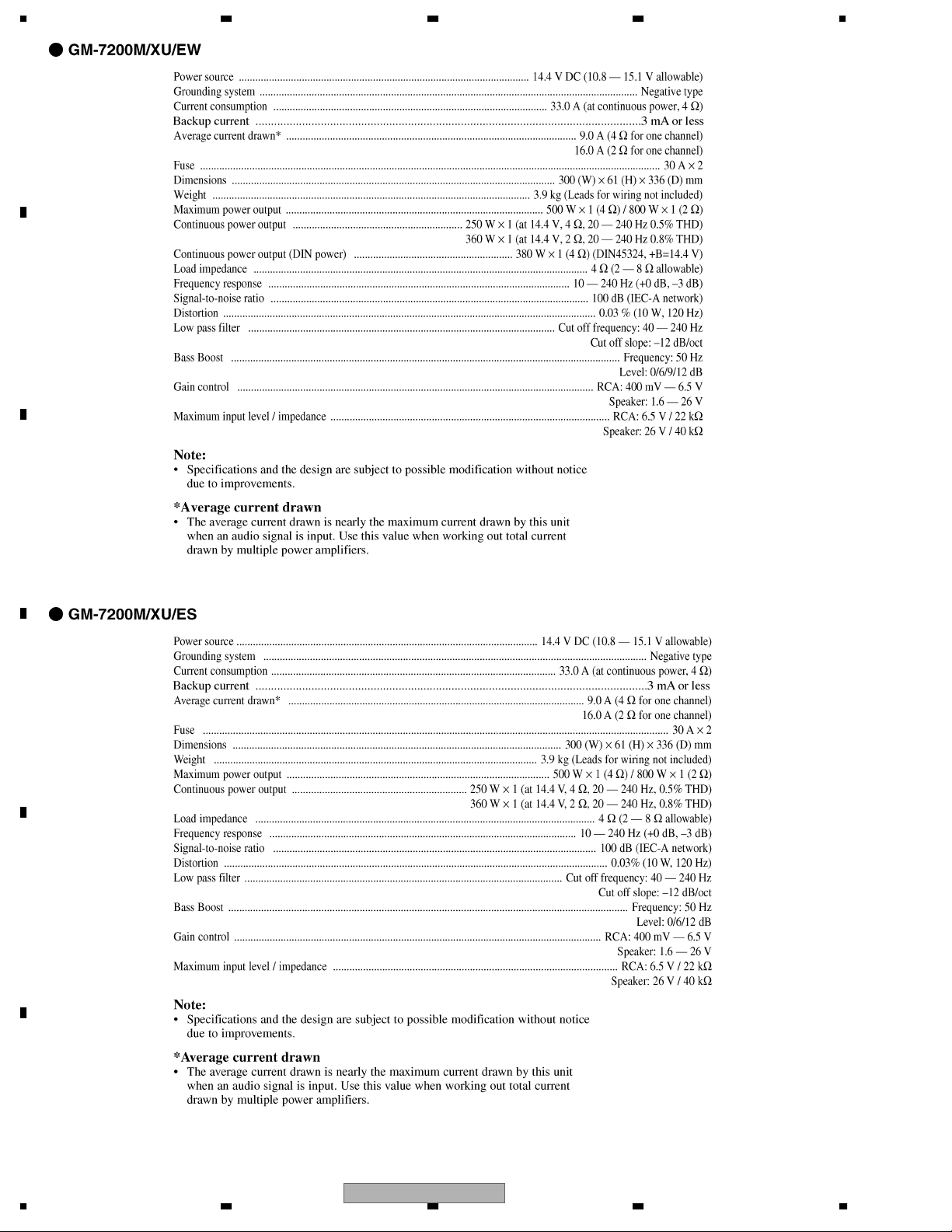
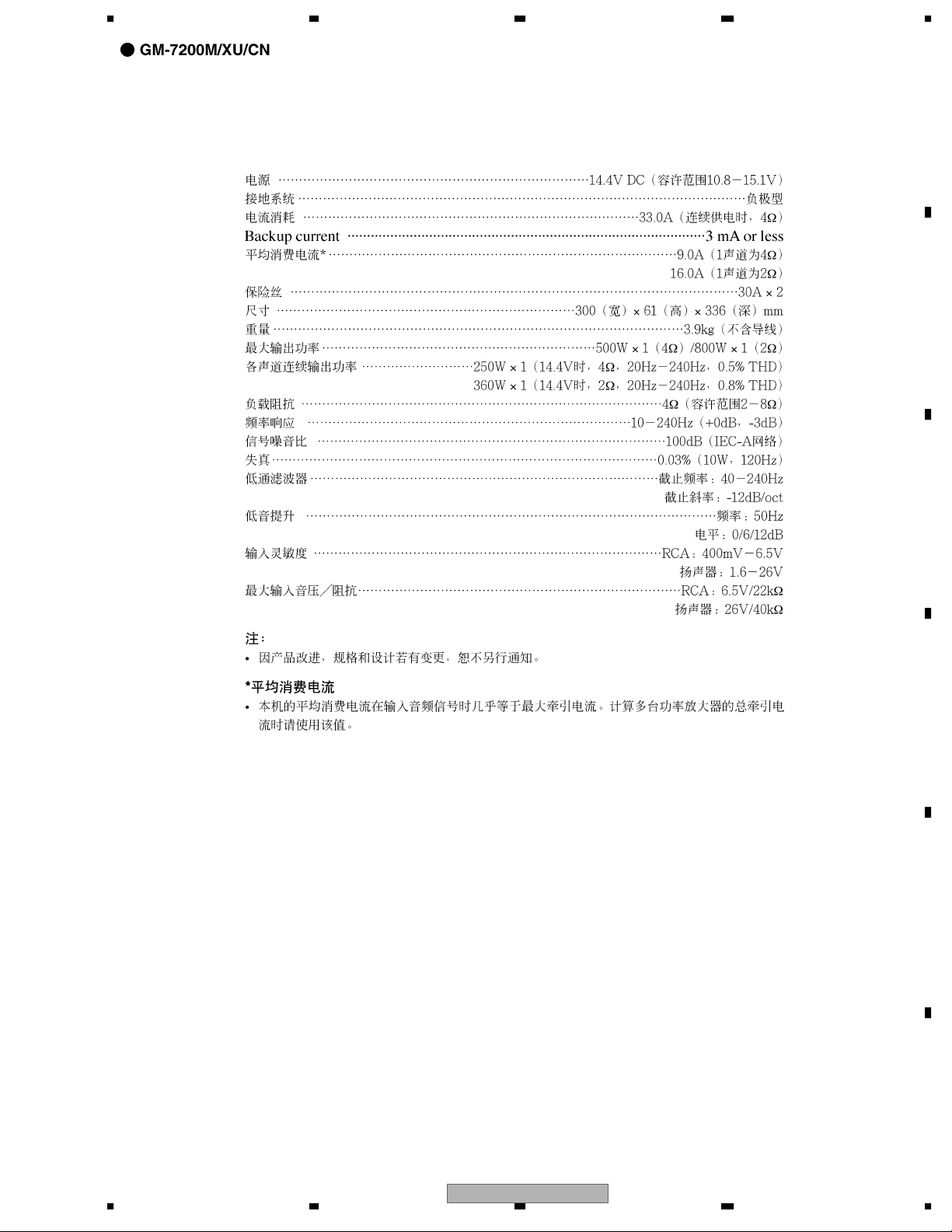
1. SPECIFICATIONS ............................................................................................................................................ 5
2. EXPLODED VIEWS AND PARTS LIST ............................................................................................................ 8
A
B
2.1 PACKING ................................................................................................................................................... 8
2.2 EXTERIOR............................................................................................................................................... 10
3. BLOCK DIAGRAM AND SCHEMATIC DIAGRAM ..........................................................................................12
3.1 SCHEMATIC DIAGRAM(GUIDE PAGE) .................................................................................................. 12
3.2 REMOTE CONTROL UNIT(EW).............................................................................................................. 18
4. PCB CONNECTION DIAGRAM ..................................................................................................................... 20
4.1 AMP UNIT................................................................................................................................................ 20
4.2 REMOTE CONTROL UNIT(EW).............................................................................................................. 24
5. ELECTRICAL PARTS LIST ............................................................................................................................ 25
6. ADJUSTMENT ............................................................................................................................................... 32
7. GENERAL INFORMATION............................................................................................................................. 33
7.1 DIAGNOSIS ............................................................................................................................................. 33
7.1.1 DISASSEMBLY ..................................................................................................................................... 33
7.1.2 CONNECTOR FUNCTION DESCRIPTION.......................................................................................... 34
7.2 IC ............................................................................................................................................................. 35
8. OPERATIONS ................................................................................................................................................ 36
C
D
E
F
4
1234
GM-7200M/XU/UC
Page 5

5678
1. SPECIFICATIONS
A
B
C
D
E
56
GM-7200M/XU/UC
F
7
8
5
Page 6
1234
A
B
C
D
E
F
6
1234
GM-7200M/XU/UC
Page 7
5678
A
B
C
D
E
56
GM-7200M/XU/UC
F
7
8
7
Page 8
N
1234
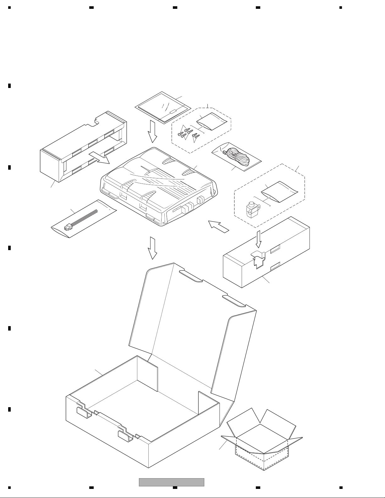
2. EXPLODED VIEWS AND PARTS LIST
OTES : • Parts marked by " * " are generally unavailable because they are not in our Master Spare Parts List.
• The > mark found on some component parts indicates the importance of the safety factor of the part.
A
Therefore, when replacing, be sure to use parts of identical designation.
• Screw adjacent to mark on the product are used for disassembly.
• For the applying amount of lubricants or glue, follow the instructions in this manual.
(In the case of no amount instructions,apply as you think it appropriate.)
2.1 PACKING
B
"
11
5
3
6
5
4
7
2
13
8
C
D
1
8
12
E
F
8
1234
9
10
GM-7200M/XU/UC
Page 9
5678
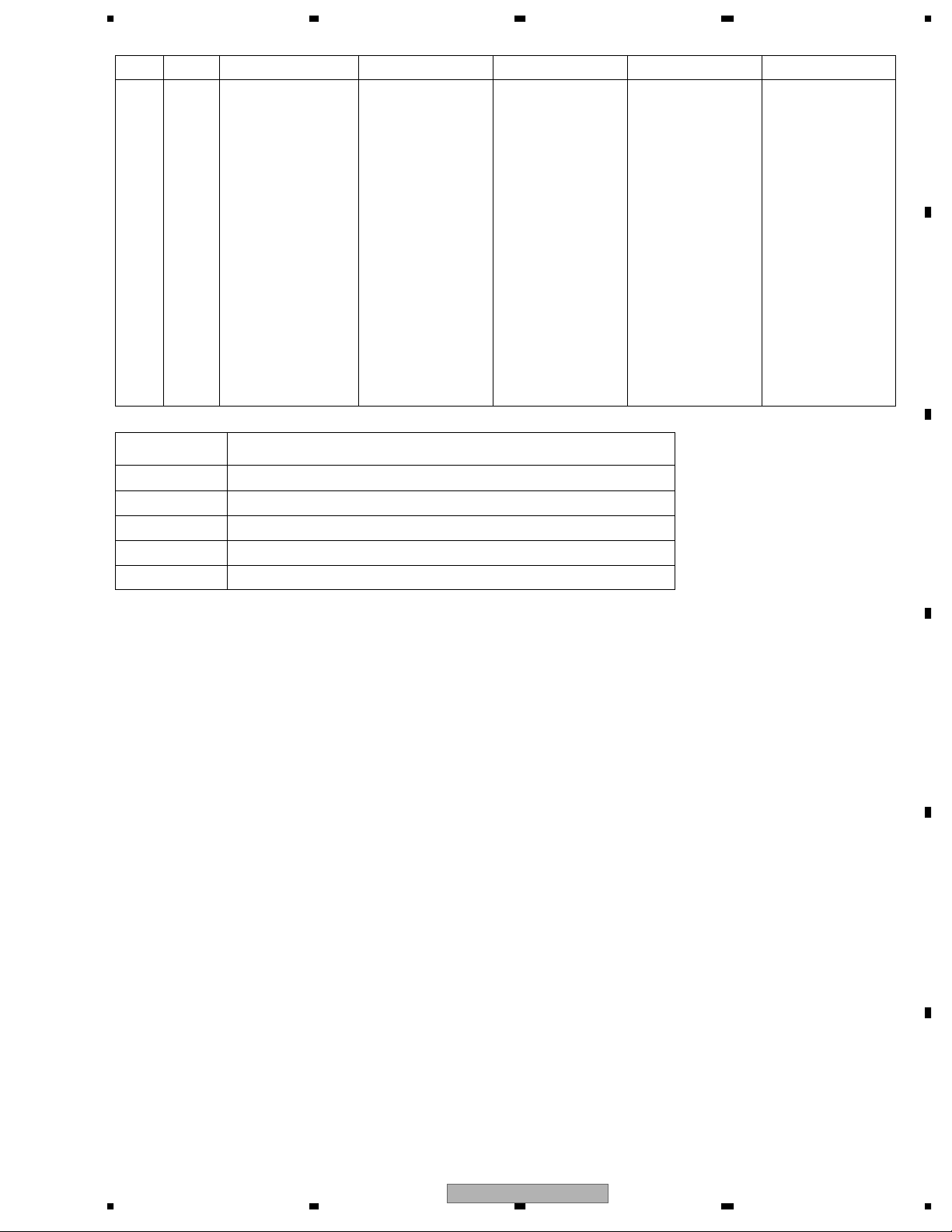
PACKING SECTION PARTS LIST
Mark No. Description GM-7200M/XU/UC GM-7200M/XU/EW GM-7200M/XU/ES GM-7200M/XU/CN
1 Cord Assy CDE7736 CDE7736 CDE7736 CDE7736
2 Cord Assy Not used CDE7804 Not used Not used
3 Screw Assy CEA5330 CEA5328 CEA5330 CEA5330
4 Screw Not used BYC30P100FTB Not used Not used
5 Screw BYC40P180FTB BYC40P180FTB BYC40P180FTB BYC40P180FTB
* 6 Polyethylene Sheet CNM4338 CNM4338 CNM4338 CNM4338
7 Polyethylene Bag CEG1351 CEG1317 CEG1317 CEG1317
8 Protector CHP3066 CHP3066 CHP3066 CHP3066
9 Carton CHG5583 CHG5582 CHG5584 CHG5585
10 Contain Box CHL5583 CHL5582 CHL5584 CHL5585
11-1 Polyethylene Bag CEG1116 CEG1116 CEG1116 CEG1116
11-2 Owner's Manual CRD4006 CRD4005 CRD4007 CRB2105
* 11-3 Warranty Card Not used CRY1157 Not used ARY7046
* 11-4 Card ARY1048 Not used Not used Not used
11-5 Owner's Manual Not used Not used CRD4008 Not used
12 Remote Control Assy Not used CXC4064 Not used Not used
* 13 Polyethylene Bag Not used CEG1171 Not used Not used
Owner's Manual
A
B
Part No. Language
CRD4006 English, French, Spanish
CRD4005 English, Spanish, German, French, Italian, Dutch, Russian
CRD4007 English, Spanish
CRD4008 Arabic, Portuguese(B)
CRB2105 Traditional Chinese
C
D
56
GM-7200M/XU/UC
E
F
7
8
9
Page 10
1234
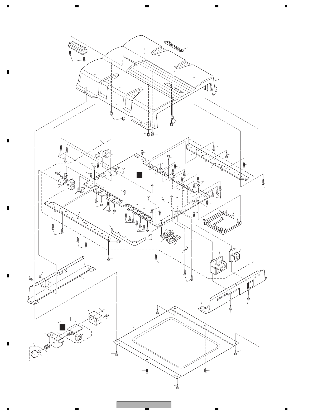
2.2 EXTERIOR
A
B
12
4
1
10
14
21
21
14
40
11
33
14
2
2
2
31
14
29
31
16
14
24
25
2
23
26
27
17
14
2
11
13
22
28
19
14
14
14
2
2
31
32
C
20
D
3
2
3
15
18
30
2
14
14
14
8
11
A
14
11
14
14
21
2
9
43
E
41
42
38
F
10
1234
36
B
35
37
43
1
GM-7200M/XU/UC
1
39
7
1
1
1
39
1
Page 11
>
5678
(1) EXTERIOR SECTION PARTS LIST
Mark No. Description Part No.
1 Screw(M3x8) CBA2011
2 Screw(M3x12) CBA2012
3 Screw BSZ30P050FTB
* 4 Badge CAH1946
5 •••••
6 •••••
7 Case CNB3199
8 Panel See Contrast table(2)
9 Panel CNB3205
10 Heat Sink See Contrast table(2)
11 Spacer CNV8256
12 Lighting Conductor CNV8692
13 Amp Unit See Contrast table(2)
14 Screw(M3x8) CBA2011
15 Pin Jack(CN111) CKB1068
16 Terminal(CN853) CKE1055
17 Terminal(CN855) CKE1057
18 Socket(CN801) CKM1463
19 Connector(CN701) See Contrast table(2)
20 Holder CND2456
21 Terminal CND2458
22 Holder CND2466
Mark No. Description Part No.
23 Buss Bar CND2467
24 Buss Bar CND2468
25 Buss Bar CND2469
26 Buss Bar CND2471
27 Buss Bar CND2472
28 Buss Bar CND2729
29 Sub Heat Sink CNR1808
30 Sub Heat Sink CNR1810
31 Screw PPZ30P100FSN
32 Screw PPZ30P100FTB
33 Terminal(CN850) VNF1084
34 •••••
35 Cover See Contrast table(2)
36 Remote Control Unit See Contrast table(2)
37 Connector(CN1351) See Contrast table(2)
38 Spring See Contrast table(2)
39 Screw PPZ30P100FTB
40 Fuse(FU100, FU101) (30A) CEK1330
41 Grille See Contrast table(2)
42 Knob Unit See Contrast table(2)
43 Screw See Contrast table(2)
A
B
C
(2) CONTRAST TABLE
GM-7200M/XU/UC, GM-7200M/XU/EW, GM-7200M/XU/ES and GM-7200M/XU/CN are constructed the same
except for the following:
Mark No. Description GM-7200M/XU/UC GM-7200M/XU/EW GM-7200M/XU/ES GM-7200M/XU/CN
8 Panel CNB3229 CNB3201 CNB3229 CNB3229
10 Heat Sink CNR1826 CNR1806 CNR1826 CNR1826
13 Amp Unit CWH1286 CWH1285 CWH1286 CWH1286
19 Connector(CN701) Not used CKS4962 Not used Not used
35 Cover Not used CNS8141 Not used Not used
36 Remote Control Unit Not used CWM9848 Not used Not used
37 Connector(CN1351) Not used CKS4962 Not used Not used
38 Spring Not used CBL1692 Not used Not used
41 Grille Not used CNS8140 Not used Not used
42 Knob Unit Not used CXC4335 Not used Not used
43 Screw Not used BPZ20P100FTB Not used Not used
D
E
56
GM-7200M/XU/UC
F
7
8
11
Page 12
A-a
A-b
A-a
A-b
A-b
A-a
T
d
1234
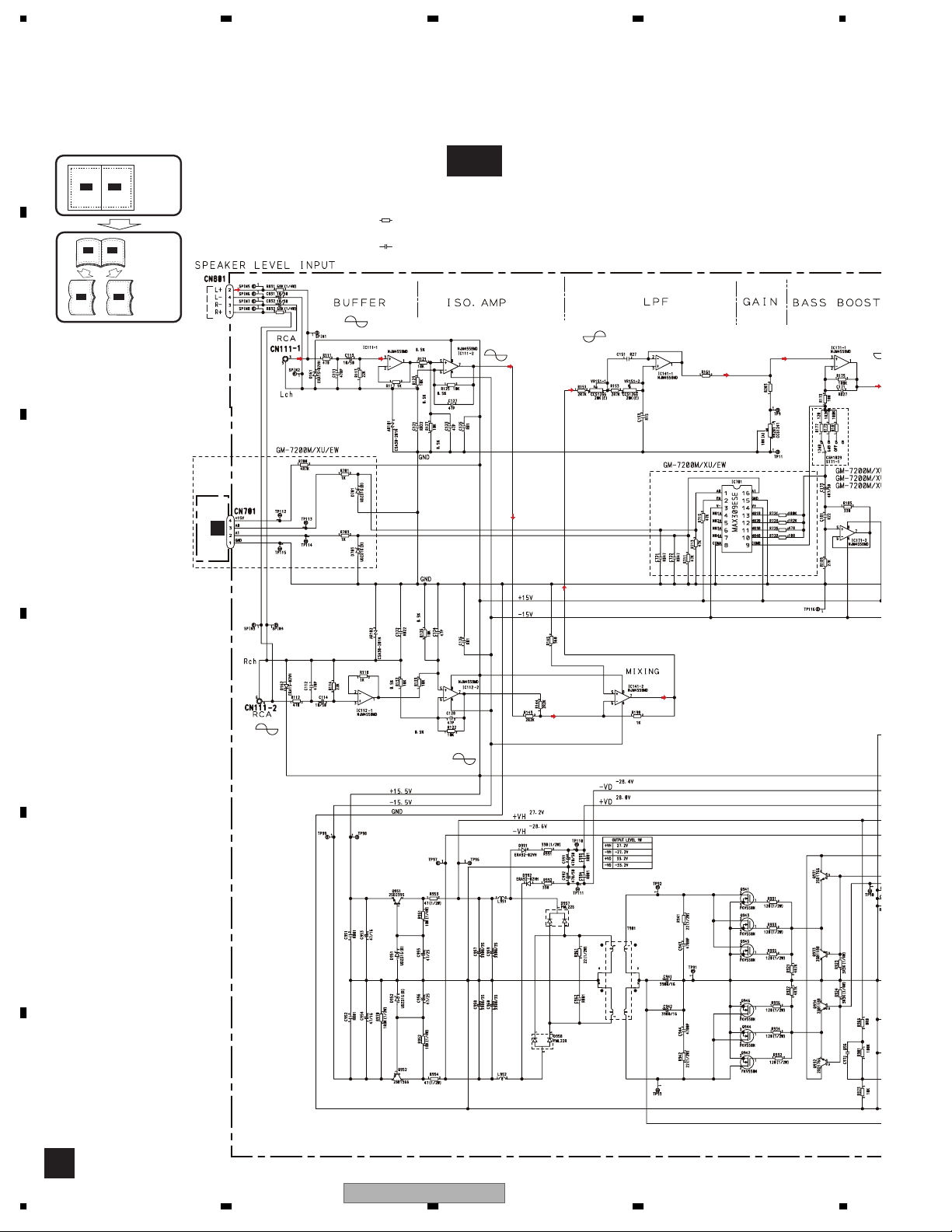
3. BLOCK DIAGRAM AND SCHEMATIC DIAGRAM
3.1 SCHEMATIC DIAGRAM(GUIDE PAGE)
A
Note: When ordering service parts, be sure to refer to " EXPLODED VIEWS AND PARTS LIST" or
"ELECTRICAL PARTS LIST".
Large size
A-b
A-b
A-b
SCH diagram
Guide page
Detailed page
CN1351
B
+18.5dBs
(BB ON
INPUT MAX)
NOTE :
Symbol indicates a resistor.
No differentiation is made between chip resistors and
discrete resistors.
Symbol indicates a capacitor.
No differentiation is made between chip capacitors and
discrete capacitors.
0dB
A-a
A-a
A-a
B
C
A-a
0dB
+18.3dBs
+17.5dBs
Decimal points for resistor
and capacitor fixed values
are expressed as :
←
2.2 2R2
←
0.022 R022
0dB
LPF
The > mark found on some component parts indicates
the importance of the safety factor of the part.
Therefore, when replacing, be sure to use parts of
identical designation.
15K
+17.5dBs
-1.7dB ~
-32.0dB
GAIN
0dB or +12dB
or +6dB ( or +9dB)
-15dBs
330
BASS BOOS
-2.6
-0.8dB
D
E
320µH
320µH
F
A
12
1234
GM-7200M/XU/UC
Page 13

s
5678
A
A-b
mponent parts indicates
tor of the part.
ure to use parts of
AMP UNIT
A
0dB or +12dB
or +6dB ( or +9dB)
0dB
-2.6dBs
B
BASS BOOST
-2.6dBs
+38dBs
C
D
BFC
56
GM-7200M/XU/UC
E
>
>
50µH
F
A
7
8
13
Page 14

A
A-b
1234
0dB
1
-2.6dBs
BASS BOOST
0dB or +12dB
or +6dB ( or +9dB)
-15dBs
330
B
GAIN
-1.7dB ~
-32.0dB
+17.5dBs
The > mark found on some component parts indicates
the importance of the safety factor of the part.
Therefore, when replacing, be sure to use parts of
identical designation.
0dB
C
←
←
Decimal points for resistor
and capacitor fixed values
are expressed as :
2.2 2R2
0.022 R022
A-b
A-a
A-a
15K
-0.8dB
LPF
+17.5dBs
+18.3dBs
D
E
F
A-a
14
0dB
Symbol indicates a resistor.
No differentiation is made between chip resistors and
discrete resistors.
Symbol indicates a capacitor.
No differentiation is made between chip capacitors and
discrete capacitors.
NOTE :
0dB
+18.5dBs
(BB ON
INPUT MAX)
B
CN1351
1234
GM-7200M/XU/UC
Page 15

5678
A
2 3
4
A-b
B
-0.8dB
C
A-b
A-a
A-a
320 H
320 H
D
E
56
GM-7200M/XU/UC
F
A-a
7
8
15
Page 16

1234
A
+38dBs
AMP UNIT
B
C
A-b
A-a
D
A
E
F
A-b
16
-2.6dBs
0dB
.6dBs
ST
1
GM-7200M/XU/UC
1234
Page 17

5678
A
>
>
B
50 H
C
A-b
A-a
BFC
2 3
GM-7200M/XU/UC
56
D
E
F
4
7
8
A-b
17
Page 18

1234
3.2 REMOTE CONTROL UNIT(EW)
A
B
REMOTE CONTROL UNIT
B
C
A
CN701
D
E
F
B
18
1234
GM-7200M/XU/UC
Page 19

5678
A
B
C
D
E
56
GM-7200M/XU/UC
F
7
8
19
Page 20

1234
4. PCB CONNECTION DIAGRAM
4.1 AMP UNIT
A
B
C
NOTE FOR PCB DIAGRAMS
1.The parts mounted on this PCB
include all necessary parts for
several destination.
For further information for
respective destinations, be sure
to check with the schematic dia gram.
2.Viewpoint of PCB diagrams
Connector
P.C.Board
Capacitor
Chip Part
SIDE A
SIDE B
A
AMP UNIT
BFC
BFC
2121
SPEAKER OUTPUTSPEAKER OUTPUTPOWER SUPPLY
3
D
12
E
321321321321321321
F
A
20
1234
GM-7200M/XU/UC
Page 21

5678
BASS BOOST
BASS BOOST
GAIN
GAIN
SIDE A
A
B
C
321
Rch
LPF
LPF
RCA IN
RCA IN
L-
LPF/OFF
LPF/OFF
Lch
R+L+R-
SPEAKER
LEBEL
INPUT
B
CN1351
D
E
56
GM-7200M/XU/UC
F
A
7
8
21
Page 22

1234
A
AMP UNIT
A
B
C
D
Rch
Lch
E
L-
R+L+R-
F
A
22
1234
GM-7200M/XU/UC
Page 23

5678
SIDE B
11
A
B
C
D
1
E
F
56
GM-7200M/XU/UC
A
7
8
23
Page 24

1234
4.2 REMOTE CONTROL UNIT(EW)
A
B
SIDE B
CN701
1
3
SIDE A
REMOTE CONTROL UNIT
B
1
REMOTE CONTROL UNIT
B
A
C
12dB
5
9dB
4
6dB
3
0dB
2
1
BASS BOOST
D
2
4
E
F
B
24
1234
GM-7200M/XU/UC
Page 25

N
5678
5. ELECTRICAL PARTS LIST
OTE:
• Parts whose parts numbers are omitted are subject to being not supplied.
• The part numbers shown below indicate chip components.
Chip Resistor
RS1/_S___J,RS1/__S___J
Chip Capacitor (except for CQS.....)
CKS....., CCS....., CSZS.....
• The > mark found on some component parts indicates the importance of the safety factor of the part.
Therefore, when replacing, be sure to use parts of identical designation.
• Meaning of the figures and others in the parentheses in the parts list.
Example) IC 301 is on the point (face A, 91 of x-axis, and 111 of y-axis) of the corresponding
PC board.
IC 301 (A, 91, 111) IC NJM2068V
A
B
Circuit Symbol and No. Part No.
Unit Number : CWH1286(UC, ES, CN)
Unit Name : Amp Unit
Unit Number : CWH1285(EW)
Unit Name : Amp Unit
Unit Number : CWM9848(EW)
Unit Name : Remote Control Unit
A
Unit Number : CWH1286(UC, ES, CN)
Unit Name : Amp Unit
MISCELLANEOUS
IC 111 (B,293,51) IC NJM4558MD
IC 112 (B,274,78) IC NJM4558MD
IC 141 (B,283,103) IC NJM4558MD
IC 171 (B,286,186) IC NJM4558MD
IC 191 (B,273,170) IC NJM4558MD
IC 651 (A,168,96) IC PA2027A
IC 901 (B,158,64) IC UPC494GS
Q 201 (B,249,137) Transistor 2SC4081
Q 202 (B,252,134) Transistor 2SC4081
Q 203 (B,251,128) Transistor DTA124EU
Q 551 (B,220,87) Transistor 2SA1163
Q 552 (B,219,137) Transistor 2SA1163
Q 553 (B,226,89) Transistor 2SA1163
Q 554 (B,214,140) Transistor 2SA1163
Q 555 (B,224,82) Transistor 2SC2713
Q 556 (B,217,128) Transistor 2SC2713
Q 557 (B,220,80) Transistor 2SC2713
Q 558 (B,211,132) Transistor 2SC2713
Q 559 (B,215,76) Transistor 2SC2713
Q 560 (B,208,147) Transistor 2SC2713
Q 561 (B,230,73) Transistor 2SA1163
Q 562 (B,241,154) Transistor 2SA1163
Q 563 (B,222,72) Transistor 2SC2713
Circuit Symbol and No. Part No.
Q 564 (B,222,151) Transistor 2SC2713
Q 565 (A,230,33) Transistor 2SD1684
Q 566 (A,219,200) Transistor 2SD1684
Q 571 (B,244,71) Transistor 2SC2713
Q 572 (B,218,121) Transistor 2SC2713
Q 581 (A,242,62) Transistor 2SC3421
Q 582 (A,240,163) Transistor 2SC3421
Q 583 (A,276,34) Transistor 2SC4388
Q 584 (A,250,199) Transistor 2SC4388
Q 585 (A,254,34) Transistor 2SC4388
Q 586 (A,228,199) Transistor 2SC4388
Q 587 (A,210,63) Transistor 2SA1358
Q 588 (A,209,154) Transistor 2SA1358
Q 589 (A,221,34) Transistor 2SA1673
Q 590 (A,173,199) Transistor 2SA1673
Q 591 (A,199,34) Transistor 2SA1673
Q 592 (A,195,199) Transistor 2SA1673
Q 660 (A,158,74) Transistor 2SB1243
Q 661 (B,153,107) Transistor 2SA1576A
Q 662 (B,151,118) Transistor 2SC4081
Q 670 (B,268,110) Transistor 2SA1576A
Q 671 (B,265,110) Transistor 2SC4081
Q 672 (B,267,102) Transistor 2SC4081
Q 673 (B,259,111) Transistor 2SC4081
Q 674 (B,262,94) Transistor 2SA1576A
Q 691 (B,176,86) Transistor DTC114TU
Q 692 (B,174,94) Transistor DTA114EU
Q 931 (B,148,52) Transistor 2SD1766
Q 932 (B,154,41) Transistor 2SD1766
Q 933 (B,143,47) Transistor 2SB1188
Q 934 (B,145,35) Transistor 2SB1188
Q 941 (A,91,31) Transistor FKV550N
Q 942 (A,136,31) Transistor FKV550N
Q 943 (A,76,31) Transistor FKV550N
Q 944 (A,121,31) Transistor FKV550N
Q 945 (A,61,31) Transistor FKV550N
Q 946 (A,106,31) Transistor FKV550N
Q 951 (A,129,203) Transistor 2SD2395
Q 952 (A,109,203) Transistor 2SB1566
Q 981 (B,137,67) Transistor 2SA1576A
Q 991 (B,140,83) Transistor 2SC4081
C
D
E
F
56
GM-7200M/XU/UC
7
8
25
Page 26

1234
Circuit Symbol and No. Part No.
Q 992 (B,144,82) Transistor DTC114TU
D 161 (A,306,66) Diode ERA15-02VH
A
D 162 (A,291,86) Diode ERA15-02VH
D 553 (B,211,74) Diode MA111
D 554 (B,232,146) Diode MA111
D 555 (B,209,74) Diode MA111
D 556 (B,234,145) Diode MA111
D 557 (B,247,71) Diode MA111
D 558 (B,226,121) Diode MA111
D 601 (B,247,117) LED FR1112H
D 658 (B,165,33) Diode DAN202U
D 661 (B,171,74) Diode MA111
D 664 (B,139,114) Diode UDZS7R5(B)
B
D 665 (A,48,99) Diode RM4Z-LFJ4
D 670 (B,262,110) Diode MA111
D 681 (A,157,105) Diode ERA15-02VH
D 682 (A,162,108) Diode ERA15-02VH
D 951 (B,145,192) Diode UDZS16(B)
D 952 (B,123,192) Diode UDZS16(B)
D 957 (A,89,202) Diode FML22S
D 958 (A,70,202) Diode FML22R
D 991 (A,124,184) Diode ERA92-02VH
D 992 (A,121,183) Diode ERA92-02VH
D 993 (B,141,78) Diode MA111
C
L 601 (A,59,69) Choke Coil 50µH CTH1323
L 951
L 952
T 901 (A,100,83) Transformer CTT1123
TH901 (A,150,33) Thermistor CCX1065
TH902 (A,148,201) Thermistor CCX1065
TH903 (A,128,102) Thermistor CCX1064
S 171
S 901 (A,8,197) Switch(BFC) HSH-156
VR151
VR201
D
FU100 (A,19,42) Fuse 30A CEK1330
FU101 (A,19,65) Fuse 30A CEK1330
AR101 (B,315,78) Surge Protector CSA30-201N
AR102 (B,309,89) Surge Protector CSA30-201N
(A,69,163) Choke Coil 320µH
(A,40,163) Choke Coil 320µH
(A,314,178) Switch(BASS BOOST)
(A,308,116) Volume 20k Ω (E)(LPF)
(A,310,151) Volume 10k Ω (A)(GAIN)
CTH1326
CTH1326
CSH1029
CCS1266
CCS1241
RESISTORS
R 111 (B,295,69) RS1/16S471J
R 112 (B,283,88) RS1/16S471J
R 113 (B,295,59) RS1/16S223J
R 114 (B,275,85) RS1/16S223J
R 117 (B,291,58) RS1/16S102J
E
R 118 (B,270,79) RS1/16S102J
R 121 (B,296,43) RS1/16S1002D
R 122 (B,273,70) RS1/16S1002D
R 123 (B,295,41) RS1/16S1002D
R 125 (B,292,41) RS1/16S1002D
R 126 (B,286,80) RS1/16S1002D
R 127 (B,291,61) RS1/16S1002D
R 132 (B,273,69) RS1/16S1002D
R 133 (B,277,70) RS1/16S1002D
R 143 (B,282,96) RS1/16S222J
F
R 144 (B,283,95) RS1/16S222J
R 145 (B,291,104) RS1/16S561J
R 151 (B,310,112) RS1/16S272J
26
1234
R 153 (B,294,115) RS1/16S272J
R 161 (B,282,121) RS1/16S153J
R 173 (B,286,176) RS1/16S101J
R 175 (B,288,181) RS1/16S182J
R 177 (B,316,178) RS1/16S121J
R 179 (B,316,182) RS1/16S122J
R 181 (B,318,182) RS1/16S104J
R 185 (B,287,193) RS1/16S331J
R 189 (B,283,195) RS1/16S273J
R 191 (B,275,179) RS1/16S222J
R 192 (B,273,162) RS1/16S222J
R 193 (B,271,177) RS1/16S222J
R 194 (B,270,164) RS1/16S222J
R 195 (B,276,176) RS1/16S122J
R 198 (B,280,97) RS1/16S102J
R 201 (B,249,140) RS1/16S472J
R 202 (B,252,131) RS1/16S472J
R 203 (B,285,173) RS1/16S331J
R 205 (B,273,158) RS1/16S222J
R 206 (B,267,165) RS1/16S222J
R 505 (B,260,35) RS1/16S124J
R 506 (B,265,199) RS1/16S124J
R 507 (B,237,35) RS1/16S124J
R 508 (B,242,199) RS1/16S124J
R 509 (B,248,77) RS1/16S564J
R 510 (B,225,123) RS1/16S564J
R 511 (B,241,72) RS1/16S473J
R 512 (B,222,122) RS1/16S473J
R 513 (A,12,201) RD1/2PM100J
R 514 (A,26,140) RD1/2PM100J
R 551 (B,229,40) RS1/16S182J
R 552 (B,221,194) RS1/16S182J
R 555 (B,236,87) RS1/16S103J
R 556 (B,228,133) RS1/16S103J
R 557 (B,236,89) RS1/16S473J
R 558 (B,225,130) RS1/16S473J
R 559 (B,231,89) RS1/16S331J
R 560 (B,225,140) RS1/16S331J
R 561 (B,233,89) RS1/16S331J
R 562 (B,225,142) RS1/16S331J
R 563 (B,221,84) RS1/16S681J
R 564 (B,216,136) RS1/16S681J
R 565 (B,211,86) RS1/16S361J
R 566 (B,226,126) RS1/16S361J
R 567 (B,209,86) RS1/16S223J
R 568 (B,222,126) RS1/16S223J
R 569 (B,211,79) RS1/16S681J
R 570 (B,209,143) RS1/16S681J
R 571 (B,235,72) RS1/16S223J
R 572 (B,228,151) RS1/16S223J
R 573 (B,231,40) RS1/16S560J
R 574 (B,219,194) RS1/16S560J
R 575 (A,233,70) RD1/4PU101J
R 576 (A,234,154) RD1/4PU101J
R 577 (B,221,65) RS1/16S681J
R 578 (B,217,152) RS1/16S681J
R 579 (B,226,71) RS1/16S181J
R 580 (B,221,144) RS1/16S181J
R 581 (B,234,67) RS1/16S100J
R 582 (B,240,158) RS1/16S100J
GM-7200M/XU/UC
Circuit Symbol and No. Part No.
>
>
Page 27

5678
Circuit Symbol and No. Part No.
R 583 (B,219,66) RS1/16S100J
R 584 (B,217,150) RS1/16S100J
Circuit Symbol and No. Part No.
R 936 (A,111,38) RD1/2PM121J
R 941 (A,72,65) RD1/2PM220J
R 585 (A,281,31) RD1/2PM100J
R 586 (A,245,202) RD1/2PM100J
R 587 (A,258,31) RD1/2PM100J
R 588 (A,224,202) RD1/2PM100J
R 589 (B,238,30) RS1/16S221J
R 590 (B,213,205) RS1/16S221J
R 591 (A,204,31) RD1/2PM100J
R 592 (A,190,202) RD1/2PM100J
R 593 (A,225,31) RD1/2PM100J
R 594 (A,168,202) RD1/2PM100J
R 595 (A,265,51) 0.1 Ω
R 596 (A,261,192) 0.1 Ω
R 597 (A,243,51) 0.1 Ω
R 598 (A,240,192) 0.1 Ω
R 599 (A,210,42) 0.1 Ω
R 600 (A,184,183) 0.1 Ω
R 601 (A,188,42) 0.1 Ω
R 602 (A,206,183) 0.1 Ω
R 621 (A,168,67) RD1/4PU101J
R 622 (A,164,72) RD1/4PU472J
R 623 (B,175,83) RS1/16S563J
R 624 (B,150,82) RS1/16S221J
R 625 (A,154,85) RD1/4PU152J
R 630 (A,163,83) RD1/4PU271J
R 631 (A,161,77) RD1/4PU471J
CCN1155
CCN1155
CCN1155
CCN1155
CCN1155
CCN1155
CCN1155
CCN1155
R 942 (A,124,54) RD1/2PM220J
R 951 (A,139,197) RD1/4PU103J
R 952 (A,112,190) RD1/4PU103J
R 953 (A,142,198) RD1/2PM470J
R 954 (A,118,201) RD1/2PM470J
R 961 (A,115,109) RD1/2PM220J
R 966 (B,126,74) RS1/16S0R0J
R 970 (A,164,199) RD1/2PM182J
R 973 (B,151,60) RS1/16S103J
R 974 (B,162,39) RS1/16S472J
R 975 (B,162,42) RS1/16S472J
R 976 (B,162,41) RS1/16S472J
R 977 (B,161,34) RS1/16S272J
R 978 (B,168,35) RS1/16S272J
R 979 (B,168,38) RS1/16S272J
R 980 (B,141,65) RS1/16S105J
R 981 (B,148,74) RS1/16S153J
R 982 (B,146,70) RS1/16S102J
R 983 (B,142,73) RS1/16S473J
R 984 (B,140,73) RS1/16S202J
R 985 (B,142,68) RS1/16S101J
R 986 (B,140,68) RS1/16S223J
R 987 (B,132,85) RS1/16S103J
R 991 (A,139,185) RD1/2PM331J
R 992 (A,125,180) RD1/2PM331J
A
B
C
R 632 (B,162,115) RS1/16S223J
R 633 (B,170,103) RS1/16S223J
R 634 (B,162,113) RS1/16S223J
R 640 (B,156,99) RS1/16S472J
R 641 (B,149,106) RS1/16S822J
R 642 (B,136,107) RS1/16S822J
R 644 (B,153,103) RS1/16S103J
R 645 (B,150,115) RS1/16S222J
R 646 (B,150,113) RS1/16S472J
R 647 (B,145,114) RS1/16S103J
R 648 (B,144,116) RS1/16S103J
R 649 (B,142,119) RS1/16S473J
R 650 (A,44,79) RD1/4PU222J
R 666 (B,39,76) RS1/16S1R0J
R 670 (B,270,115) RS1/16S104J
R 671 (B,267,114) RS1/16S472J
R 672 (A,263,104) RD1/4PU103J
R 673 (B,268,96) RS1/16S562J
R 674 (B,253,110) RS1/16S472J
R 675 (B,251,110) RS1/16S222J
R 676 (A,265,97) RD1/4PU221J
R 831 (A,304,63) RD1/4PU683J
R 832 (A,307,62) RD1/4PU683J
R 901 (B,140,62) RS1/16S104J
R 921 (B,139,46) RS1/16S472J
R 922 (B,139,42) RS1/16S472J
R 923 (A,147,47) RD1/4PU332J
R 924 (A,158,31) RD1/4PU332J
R 931 (A,95,38) RD1/2PM121J
R 932 (A,141,31) RD1/2PM121J
R 933 (A,80,38) RD1/2PM121J
R 934 (A,125,38) RD1/2PM121J
R 935 (A,65,38) RD1/2PM121J
56
R 993 (B,138,79) RS1/16S222J
R 998 (B,269,121) RS1/16S0R0J
CAPACITORS
C 111 (B,297,62) CKSRYB471K50
C 112 (B,283,86) CKSRYB471K50
C 113 (A,299,61) CEAT100M50
C 114 (A,279,89) CEAT100M50
C 121 (A,284,68) CFTNA223J50
C 122 (A,284,72) CFTNA223J50
C 123 (B,289,61) CCSRCH470J50
C 124 (B,286,78) CCSRCH470J50
C 125 (A,286,63) CFTNA103J50
C 126 (A,283,76) CFTNA103J50
C 127 (B,292,43) CCSRCH470J50
C 128 (B,273,72) CCSRCH470J50
C 151 (A,283,117) CFTNA274J50
C 153 (A,287,102) CFTNA154J50
C 171 (A,289,173) CFTNA273J50
C 173 (A,310,202) CEANP4R7M50
C 181 (A,298,200) CFTNA224J50
C 551 (A,239,84) CEAT100M50
C 552 (A,232,136) CEAT100M50
C 553 (B,236,90) CKSRYB153K50
C 554 (B,227,130) CKSRYB153K50
C 555 (B,218,84) CKSRYB471K50
C 556 (B,212,136) CKSRYB471K50
C 559 (A,210,91) CEAT221M10
C 560 (A,229,125) CEAT221M10
C 561 (B,208,86) CCSRCH150J50
C 562 (B,222,127) CCSRCH150J50
C 563 (B,228,70) CCSRCH221J50
GM-7200M/XU/UC
D
E
F
7
8
27
Page 28

1234
Circuit Symbol and No. Part No.
C 564 (B,244,158) CCSRCH221J50
C 565 (A,230,65) CFTNA223J50
A
C 566 (A,218,157) CFTNA223J50
C 567 (A,38,201) CFTNA333J50
C 568 (A,26,155) CFTNA333J50
C 569 (A,31,203) CQHA102J2A
C 570 (A,26,144) CQHA102J2A
Circuit Symbol and No. Part No.
A
Unit Number : CWH1285(EW)
Unit Name : Amp Unit
MISCELLANEOUS
C 571 (B,238,67) CCSRCH220J50
C 572 (B,244,161) CCSRCH220J50
C 573 (B,216,66) CCSRCH220J50
C 574 (B,214,151) CCSRCH220J50
C 575 (B,239,63) CCSRCH220J50
C 576 (B,244,163) CCSRCH220J50
B
C 577 (B,218,63) CCSRCH220J50
C 578 (B,213,153) CCSRCH220J50
C 581 (A,279,44) CFTNA103J50
C 582 (A,268,195) CFTNA103J50
C 650 (A,136,86) CEAT220M25
C 651 (A,174,77) CEAT471M16
C 652 (A,171,114) CFTNA103J50
C 653 (A,158,117) CFTNA103J50
C 671 (A,175,102) CEAT101M16
C 672 (A,171,118) CFTNA103J50
C 673 (A,143,109) CEAT100M50
C
C 674 (A,141,103) CEAT100M50
C 675 (A,166,101) CFTNA103J50
C 676 (A,133,119) CFTNA103J50
C 677 (A,25,86) CFTNA224J50
C 681 (A,271,118) CEANP221M10
C 691 (A,178,94) CEAT220M25
C 831 (A,311,38) CEAT100M50
C 832 (A,301,38) CEAT100M50
IC 111 (B,293,51) IC NJM4558MD
IC 112 (B,274,78) IC NJM4558MD
IC 141 (B,283,103) IC NJM4558MD
IC 171 (B,286,186) IC NJM4558MD
IC 191 (B,273,170) IC NJM4558MD
IC 651 (A,168,96) IC PA2027A
IC 701 (B,271,139) IC MAX309ESE
IC 901 (B,158,64) IC UPC494GS
Q 201 (B,249,137) Transistor 2SC4081
Q 202 (B,252,134) Transistor 2SC4081
Q 203 (B,251,128) Transistor DTA124EU
Q 551 (B,220,87) Transistor 2SA1163
Q 552 (B,219,137) Transistor 2SA1163
Q 553 (B,226,89) Transistor 2SA1163
Q 554 (B,214,140) Transistor 2SA1163
Q 555 (B,224,82) Transistor 2SC2713
Q 556 (B,217,128) Transistor 2SC2713
Q 557 (B,220,80) Transistor 2SC2713
Q 558 (B,211,132) Transistor 2SC2713
Q 559 (B,215,76) Transistor 2SC2713
Q 560 (B,208,147) Transistor 2SC2713
Q 561 (B,230,73) Transistor 2SA1163
Q 562 (B,241,154) Transistor 2SA1163
Q 563 (B,222,72) Transistor 2SC2713
Q 564 (B,222,151) Transistor 2SC2713
C 903 (A,149,67) CEAT2R2M50
C 941 (A,66,98) 3900µF/16V CCH1644(P35)
C 942 (A,67,81) 3900µF/16V CCH1644(P35)
D
C 943 (A,70,50) CQHA472J2A
C 944 (A,129,49) CQHA472J2A
C 951 (A,150,193) CQHA102J2A
C 952 (A,123,199) CQHA102J2A
C 953 (A,157,194) CEAT470M16
C 954 (A,128,191) CEAT470M16
C 955 (A,134,191) CEAT470M25
C 956 (A,114,195) CEAT470M25
C 957 (A,62,132) 3900µF/35V CCH1645(P35)
C 958 (A,42,132) 3900µF/35V CCH1645(P35)
C 959 (A,62,153) 3900µF/35V CCH1645(P35)
E
C 960 (A,42,152) 3900µF/35V CCH1645(P35)
C 962 (A,109,122) CQHA102J2A
C 970 (A,172,61) CFTNA103J50
C 971 (A,132,64) CFTNA564J50
C 972 (A,167,64) CEAT101M16
C 973 (A,151,74) CQHA102J2A
C 974 (A,144,72) CEAT221M16
C 975 (A,132,74) CEANP470M16
C 980 (A,144,53) CFTNA103J50
C 991 (A,145,179) CEAT471M50(P45)
C 992 (A,120,177) CEAT471M50(P45)
F
C 993 (A,135,173) CQHA102J2A
C 994 (A,130,173) CQHA102J2A
28
1234
Q 565 (A,230,33) Transistor 2SD1684
Q 566 (A,219,200) Transistor 2SD1684
Q 571 (B,244,71) Transistor 2SC2713
Q 572 (B,218,121) Transistor 2SC2713
Q 581 (A,242,62) Transistor 2SC3421
Q 582 (A,240,163) Transistor 2SC3421
Q 583 (A,276,34) Transistor 2SC4388
Q 584 (A,250,199) Transistor 2SC4388
Q 585 (A,254,34) Transistor 2SC4388
Q 586 (A,228,199) Transistor 2SC4388
Q 587 (A,210,63) Transistor 2SA1358
Q 588 (A,209,154) Transistor 2SA1358
Q 589 (A,221,34) Transistor 2SA1673
Q 590 (A,173,199) Transistor 2SA1673
Q 591 (A,199,34) Transistor 2SA1673
Q 592 (A,195,199) Transistor 2SA1673
Q 660 (A,158,74) Transistor 2SB1243
Q 661 (B,153,107) Transistor 2SA1576A
Q 662 (B,151,118) Transistor 2SC4081
Q 670 (B,268,110) Transistor 2SA1576A
Q 671 (B,265,110) Transistor 2SC4081
Q 672 (B,267,102) Transistor 2SC4081
Q 673 (B,259,111) Transistor 2SC4081
Q 674 (B,262,94) Transistor 2SA1576A
Q 691 (B,176,86) Transistor DTC114TU
Q 692 (B,174,94) Transistor DTA114EU
Q 931 (B,148,52) Transistor 2SD1766
Q 932 (B,154,41) Transistor 2SD1766
GM-7200M/XU/UC
Page 29

5678
Circuit Symbol and No. Part No.
Q 933 (B,143,47) Transistor 2SB1188
Q 934 (B,145,35) Transistor 2SB1188
Q 941 (A,91,31) Transistor FKV550N
Q 942 (A,136,31) Transistor FKV550N
Q 943 (A,76,31) Transistor FKV550N
Q 944 (A,121,31) Transistor FKV550N
Q 945 (A,61,31) Transistor FKV550N
Q 946 (A,106,31) Transistor FKV550N
Q 951 (A,129,203) Transistor 2SD2395
Q 952 (A,109,203) Transistor 2SB1566
Q 981 (B,137,67) Transistor 2SA1576A
Q 991 (B,140,83) Transistor 2SC4081
Q 992 (B,144,82) Transistor DTC114TU
D 161 (A,306,66) Diode ERA15-02VH
D 162 (A,291,86) Diode ERA15-02VH
D 553 (B,211,74) Diode MA111
D 554 (B,232,146) Diode MA111
D 555 (B,209,74) Diode MA111
D 556 (B,234,145) Diode MA111
D 557 (B,247,71) Diode MA111
D 558 (B,226,121) Diode MA111
D 601 (B,247,117) LED FR1112H
D 658 (B,165,33) Diode DAN202U
D 661 (B,171,74) Diode MA111
D 664 (B,139,114) Diode UDZS7R5(B)
D 665 (A,48,99) Diode RM4Z-LFJ4
D 670 (B,262,110) Diode MA111
D 681 (A,157,105) Diode ERA15-02VH
D 682 (A,162,108) Diode ERA15-02VH
D 701 (B,292,135) Diode UDZS16(B)
D 703 (B,297,131) Diode UDZS16(B)
D 951 (B,145,192) Diode UDZS16(B)
D 952 (B,123,192) Diode UDZS16(B)
D 957 (A,89,202) Diode FML22S
D 958 (A,70,202) Diode FML22R
D 991 (A,124,184) Diode ERA92-02VH
D 992 (A,121,183) Diode ERA92-02VH
D 993 (B,141,78) Diode MA111
L 601 (A,59,69) Choke Coil 50µH CTH1323
L 951
L 952
T 901 (A,100,83) Transformer CTT1123
TH901 (A,150,33) Thermistor CCX1065
TH902 (A,148,201) Thermistor CCX1065
TH903 (A,128,102) Thermistor CCX1064
S 901 (A,8,197) Switch(BFC) HSH-156
VR151
VR201
>FU100 (A,19,42) Fuse 30A CEK1330
>FU101 (A,19,65) Fuse 30A CEK1330
AR101 (B,315,78) Surge Protector CSA30-201N
AR102 (B,309,89) Surge Protector CSA30-201N
(A,69,163) Choke Coil 320µH
(A,40,163) Choke Coil 320µH
(A,308,116) Volume 20kΩ(E)(LPF)
(A,310,151) Volume 10kΩ(A)(GAIN)
CTH1326
CTH1326
CCS1266
CCS1241
RESISTORS
R 111 (B,295,69) RS1/16S471J
R 112 (B,283,88) RS1/16S471J
R 113 (B,295,59) RS1/16S223J
R 114 (B,275,85) RS1/16S223J
R 117 (B,291,58) RS1/16S102J
56
Circuit Symbol and No. Part No.
R 118 (B,270,79) RS1/16S102J
R 121 (B,296,43) RS1/16S1002D
R 122 (B,273,70) RS1/16S1002D
R 123 (B,295,41) RS1/16S1002D
R 125 (B,292,41) RS1/16S1002D
R 126 (B,286,80) RS1/16S1002D
R 127 (B,291,61) RS1/16S1002D
R 132 (B,273,69) RS1/16S1002D
R 133 (B,277,70) RS1/16S1002D
R 143 (B,282,96) RS1/16S222J
R 144 (B,283,95) RS1/16S222J
R 145 (B,291,104) RS1/16S561J
R 151 (B,310,112) RS1/16S272J
R 153 (B,294,115) RS1/16S272J
R 161 (B,282,121) RS1/16S153J
R 173 (B,286,176) RS1/16S101J
R 175 (B,288,181) RS1/16S182J
R 185 (B,287,193) RS1/16S331J
R 189 (B,283,195) RS1/16S273J
R 191 (B,275,179) RS1/16S222J
R 192 (B,273,162) RS1/16S222J
R 193 (B,271,177) RS1/16S222J
R 194 (B,270,164) RS1/16S222J
R 195 (B,276,176) RS1/16S122J
R 198 (B,280,97) RS1/16S102J
R 201 (B,249,140) RS1/16S472J
R 202 (B,252,131) RS1/16S472J
R 203 (B,285,173) RS1/16S331J
R 205 (B,273,158) RS1/16S222J
R 206 (B,267,165) RS1/16S222J
R 505 (B,260,35) RS1/16S124J
R 506 (B,265,199) RS1/16S124J
R 507 (B,237,35) RS1/16S124J
R 508 (B,242,199) RS1/16S124J
R 509 (B,248,77) RS1/16S564J
R 510 (B,225,123) RS1/16S564J
R 511 (B,241,72) RS1/16S473J
R 512 (B,222,122) RS1/16S473J
R 513 (A,12,201) RD1/2PM100J
R 514 (A,26,140) RD1/2PM100J
R 551 (B,229,40) RS1/16S182J
R 552 (B,221,194) RS1/16S182J
R 555 (B,236,87) RS1/16S103J
R 556 (B,228,133) RS1/16S103J
R 557 (B,236,89) RS1/16S473J
R 558 (B,225,130) RS1/16S473J
R 559 (B,231,89) RS1/16S331J
R 560 (B,225,140) RS1/16S331J
R 561 (B,233,89) RS1/16S331J
R 562 (B,225,142) RS1/16S331J
R 563 (B,221,84) RS1/16S681J
R 564 (B,216,136) RS1/16S681J
R 565 (B,211,86) RS1/16S361J
R 566 (B,226,126) RS1/16S361J
R 567 (B,209,86) RS1/16S223J
R 568 (B,222,126) RS1/16S223J
R 569 (B,211,79) RS1/16S681J
R 570 (B,209,143) RS1/16S681J
R 571 (B,235,72) RS1/16S223J
R 572 (B,228,151) RS1/16S223J
GM-7200M/XU/UC
A
B
C
D
E
F
7
8
29
Page 30

1234
Circuit Symbol and No. Part No.
Circuit Symbol and No. Part No.
R 573 (B,231,40) RS1/16S560J
R 574 (B,219,194) RS1/16S560J
A
R 575 (A,233,70) RD1/4PU101J
R 576 (A,234,154) RD1/4PU101J
R 577 (B,221,65) RS1/16S681J
R 578 (B,217,152) RS1/16S681J
R 579 (B,226,71) RS1/16S181J
R 580 (B,221,144) RS1/16S181J
R 581 (B,234,67) RS1/16S100J
R 582 (B,240,158) RS1/16S100J
R 583 (B,219,66) RS1/16S100J
R 584 (B,217,150) RS1/16S100J
R 585 (A,281,31) RD1/2PM100J
B
R 586 (A,245,202) RD1/2PM100J
R 587 (A,258,31) RD1/2PM100J
R 588 (A,224,202) RD1/2PM100J
R 589 (B,238,30) RS1/16S221J
R 590 (B,213,205) RS1/16S221J
R 591 (A,204,31) RD1/2PM100J
R 592 (A,190,202) RD1/2PM100J
R 593 (A,225,31) RD1/2PM100J
R 594 (A,168,202) RD1/2PM100J
R 595 (A,265,51) R1Ω CCN1155
R 596 (A,261,192) R1Ω CCN1155
C
R 597 (A,243,51) R1Ω CCN1155
R 703 (B,297,127) RS1/16S102J
R 711 (B,292,131) RS1/16S473J
R 713 (B,297,139) RS1/16S473J
R 715 (B,266,144) RS1/16S473J
R 721 (B,269,132) RS1/16S104J
R 723 (B,270,132) RS1/16S122J
R 725 (B,272,132) RS1/16S471J
R 727 (B,278,131) RS1/16S101J
R 831 (A,304,63) RD1/4PU683J
R 832 (A,307,62) RD1/4PU683J
R 901 (B,140,62) RS1/16S104J
R 921 (B,139,46) RS1/16S472J
R 922 (B,139,42) RS1/16S472J
R 923 (A,147,47) RD1/4PU332J
R 924 (A,158,31) RD1/4PU332J
R 931 (A,95,38) RD1/2PM121J
R 932 (A,141,31) RD1/2PM121J
R 933 (A,80,38) RD1/2PM121J
R 934 (A,125,38) RD1/2PM121J
R 935 (A,65,38) RD1/2PM121J
R 936 (A,111,38) RD1/2PM121J
R 941 (A,72,65) RD1/2PM220J
R 942 (A,124,54) RD1/2PM220J
R 951 (A,139,197) RD1/4PU103J
R 952 (A,112,190) RD1/4PU103J
R 598 (A,240,192) R1Ω CCN1155
R 599 (A,210,42) R1Ω CCN1155
R 600 (A,184,183) R1Ω CCN1155
R 601 (A,188,42) R1Ω CCN1155
R 602 (A,206,183) R1Ω CCN1155
R 621 (A,168,67) RD1/4PU101J
R 622 (A,164,72) RD1/4PU472J
R 623 (B,175,83) RS1/16S563J
R 624 (B,150,82) RS1/16S221J
R 625 (A,154,85) RD1/4PU152J
D
R 630 (A,163,83) RD1/4PU271J
R 631 (A,161,77) RD1/4PU471J
R 632 (B,162,115) RS1/16S223J
R 633 (B,170,103) RS1/16S223J
R 634 (B,162,113) RS1/16S223J
R 640 (B,156,99) RS1/16S472J
R 641 (B,149,106) RS1/16S822J
R 642 (B,136,107) RS1/16S822J
R 644 (B,153,103) RS1/16S103J
R 645 (B,150,115) RS1/16S222J
E
R 646 (B,150,113) RS1/16S472J
R 647 (B,145,114) RS1/16S103J
R 648 (B,144,116) RS1/16S103J
R 649 (B,142,119) RS1/16S473J
R 650 (A,44,79) RD1/4PU222J
R 666 (B,39,76) RS1/16S1R0J
R 670 (B,270,115) RS1/16S104J
R 671 (B,267,114) RS1/16S472J
R 672 (A,263,104) RD1/4PU103J
R 673 (B,268,96) RS1/16S562J
R 674 (B,253,110) RS1/16S472J
F
R 675 (B,251,110) RS1/16S222J
R 676 (A,265,97) RD1/4PU221J
R 700 (B,307,127) RS1/16S472J
R 701 (B,299,144) RS1/16S102J
30
1234
R 953 (A,142,198) RD1/2PM470J
R 954 (A,118,201) RD1/2PM470J
R 961 (A,115,109) RD1/2PM220J
R 966 (B,126,74) RS1/16S0R0J
R 970 (A,164,199) RD1/2PM182J
R 973 (B,151,60) RS1/16S103J
R 974 (B,162,39) RS1/16S472J
R 975 (B,162,42) RS1/16S472J
R 976 (B,162,41) RS1/16S472J
R 977 (B,161,34) RS1/16S272J
R 978 (B,168,35) RS1/16S272J
R 979 (B,168,38) RS1/16S272J
R 980 (B,141,65) RS1/16S105J
R 981 (B,148,74) RS1/16S153J
R 982 (B,146,70) RS1/16S102J
R 983 (B,142,73) RS1/16S473J
R 984 (B,140,73) RS1/16S202J
R 985 (B,142,68) RS1/16S101J
R 986 (B,140,68) RS1/16S223J
R 987 (B,132,85) RS1/16S103J
R 991 (A,139,185) RD1/2PM331J
R 992 (A,125,180) RD1/2PM331J
R 993 (B,138,79) RS1/16S222J
R 998 (B,269,121) RS1/16S0R0J
CAPACITORS
C 111 (B,297,62) CKSRYB471K50
C 112 (B,283,86) CKSRYB471K50
C 113 (A,299,61) CEAT100M50
C 114 (A,279,89) CEAT100M50
C 121 (A,284,68) CFTNA223J50
C 122 (A,284,72) CFTNA223J50
C 123 (B,289,61) CCSRCH470J50
C 124 (B,286,78) CCSRCH470J50
GM-7200M/XU/UC
Page 31

5678
Circuit Symbol and No. Part No.
C 125 (A,286,63) CFTNA103J50
C 126 (A,283,76) CFTNA103J50
Circuit Symbol and No. Part No.
C 952 (A,123,199) CQHA102J2A
C 953 (A,157,194) CEAT470M16
C 127 (B,292,43) CCSRCH470J50
C 128 (B,273,72) CCSRCH470J50
C 151 (A,283,117) CFTNA274J50
C 153 (A,287,102) CFTNA154J50
C 171 (A,289,173) CFTNA273J50
C 173 (A,310,202) CEANP4R7M50
C 181 (A,298,200) CFTNA224J50
C 551 (A,239,84) CEAT100M50
C 552 (A,232,136) CEAT100M50
C 553 (B,236,90) CKSRYB153K50
C 554 (B,227,130) CKSRYB153K50
C 555 (B,218,84) CKSRYB471K50
C 556 (B,212,136) CKSRYB471K50
C 559 (A,210,91) CEAT221M10
C 560 (A,229,125) CEAT221M10
C 561 (B,208,86) CCSRCH150J50
C 562 (B,222,127) CCSRCH150J50
C 563 (B,228,70) CCSRCH221J50
C 564 (B,244,158) CCSRCH221J50
C 565 (A,230,65) CFTNA223J50
C 566 (A,218,157) CFTNA223J50
C 567 (A,38,201) CFTNA333J50
C 568 (A,26,155) CFTNA333J50
C 569 (A,31,203) CQHA102J2A
C 570 (A,26,144) CQHA102J2A
C 571 (B,238,67) CCSRCH220J50
C 572 (B,244,161) CCSRCH220J50
C 573 (B,216,66) CCSRCH220J50
C 574 (B,214,151) CCSRCH220J50
C 575 (B,239,63) CCSRCH220J50
C 576 (B,244,163) CCSRCH220J50
C 577 (B,218,63) CCSRCH220J50
C 578 (B,213,153) CCSRCH220J50
C 581 (A,279,44) CFTNA103J50
C 582 (A,268,195) CFTNA103J50
C 954 (A,128,191) CEAT470M16
C 955 (A,134,191) CEAT470M25
C 956 (A,114,195) CEAT470M25
C 957 (A,62,132) 3900µF/35V CCH1645(P35)
C 958 (A,42,132) 3900µF/35V CCH1645(P35)
C 959 (A,62,153) 3900µF/35V CCH1645(P35)
C 960 (A,42,152) 3900µF/35V CCH1645(P35)
C 962 (A,109,122) CQHA102J2A
C 970 (A,172,61) CFTNA103J50
C 971 (A,132,64) CFTNA564J50
C 972 (A,167,64) CEAT101M16
C 973 (A,151,74) CQHA102J2A
C 974 (A,144,72) CEAT221M16
C 975 (A,132,74) CEANP470M16
C 980 (A,144,53) CFTNA103J50
C 991 (A,145,179) CEAT471M50(P45)
C 992 (A,120,177) CEAT471M50(P45)
C 993 (A,135,173) CQHA102J2A
C 994 (A,130,173) CQHA102J2A
B
Unit Number : CWM9848(EW)
Unit Name : Remote Control Unit
MISCELLANEOUS
Q 1351 (B,21,23) Transistor DTC114EU
Q 1352 (B,22,6) Transistor DTC114EU
D 1351 (B,12,25) Diode DAN202U
D 1352 (B,16,6) Diode DAN202U
D 1366 (B,21,11) Diode UDZS16(B)
D 1367 (B,29,16) Diode UDZS16(B)
S 1351
RESISTORS
(A,6,11) Switch(BASS BOOST)
CSD1128
A
B
C
D
C 650 (A,136,86) CEAT220M25
C 651 (A,174,77) CEAT471M16
C 652 (A,171,114) CFTNA103J50
C 653 (A,158,117) CFTNA103J50
C 671 (A,175,102) CEAT101M16
C 672 (A,171,118) CFTNA103J50
C 673 (A,143,109) CEAT100M50
C 674 (A,141,103) CEAT100M50
C 675 (A,166,101) CFTNA103J50
C 676 (A,133,119) CFTNA103J50
C 677 (A,25,86) CFTNA224J50
C 681 (A,271,118) CEANP221M10
C 691 (A,178,94) CEAT220M25
C 721 (A,295,142) CFTNA473J50
C 722 (A,295,126) CFTNA473J50
C 831 (A,311,38) CEAT100M50
C 832 (A,301,38) CEAT100M50
C 903 (A,149,67) CEAT2R2M50
C 941 (A,66,98) 3900µF/16V CCH1644(P35)
C 942 (A,67,81) 3900µF/16V CCH1644(P35)
C 943 (A,70,50) CQHA472J2A
C 944 (A,129,49) CQHA472J2A
C 951 (A,150,193) CQHA102J2A
56
R 1351 (B,15,16) RS1/16S103J
R 1352 (B,18,18) RS1/16S102J
R 1353 (B,31,21) RS1/16S103J
R 1354 (B,31,16) RS1/16S102J
R 1359 (B,16,8) RS1/16S102J
GM-7200M/XU/UC
E
F
7
8
31
Page 32

1234
6. ADJUSTMENT
There is no information to be shown in this chapter.
A
B
C
D
E
F
32
1234
GM-7200M/XU/UC
Page 33

5678
7. GENERAL INFORMATION
7.1 DIAGNOSIS
7.1.1 DISASSEMBLY
- Removing the Case (Fig.1)
1
Remove the six screws and then remove
the Case.
A
1
1
1
B
- Removing the Amp Unit (Fig.2)
1
Remove the fifteen screws and then
remove the Amp Unit.
1
1
Case
1
1
1
1
1
1
1
1
1 1
1
1
1
1
Fig.1
C
1
D
1
56
GM-7200M/XU/UC
Amp Unit
7
Fig.2
8
E
F
33
Page 34

1234
7.1.2 CONNECTOR FUNCTION DESCRIPTION
GM-7200M/XU/UC , GM-7200M/XU/ES , GM-7200M/XU/CN
A
B
GM-7200M/XU/EW
C
D
GM-7200M/XU/UC , GM-7200M/XU/EW , GM-7200M/XU/ES , GM-7200M/XU/CN
E
F
34
1234
GM-7200M/XU/UC
Page 35

7.2 IC
5678
*MAX309ESE
A0
EN
V-
NO1A
1
2
3
4
NO1A
NO2A
NO3A
NO4A
NO1B
NO2B
NO3B
V+
A
16
15
V-
GND
14
13
A1
GND
V+
NO1B
B
C
NO2A
NO3A
NO4A
COMA
5
6
7
8
NO4B
CMOS DECODE LOGIC
A1
A0
9
NO2B
NO3B
N04B
COMB
EN
12
11
10
IC's marked by * are MOS type.
Be careful in handling them because they are very
liable to be damaged by electrostatic induction.
D
E
56
GM-7200M/XU/UC
F
7
8
35
Page 36

1234
8. OPERATIONS
A
B
C
D
E
F
36
1234
GM-7200M/XU/UC
Page 37

5678
A
B
C
D
E
56
GM-7200M/XU/UC
F
7
8
37
Page 38

1234
A
B
C
D
E
F
38
1234
GM-7200M/XU/UC
Page 39

5678
A
B
C
D
E
56
GM-7200M/XU/UC
F
7
8
39
Page 40

1234
A
B
C
D
E
F
40
1234
GM-7200M/XU/UC
 Loading...