

Page 1
PIONEER CORPORATION 4-1, Meguro 1-Chome, Meguro-ku, Tokyo 153-8654, Japan
PIONEER ELECTRONICS (USA) INC. P.O.Box 1760, Long Beach, CA 90801-1760 U.S.A.
PIONEER EUROPE NV Haven 1087 Keetberglaan 1, 9120 Melsele, Belgium
PIONEER ELECTRONICS ASIACENTRE PTE.LTD. 253 Alexandra Road, #04-01, Singapore 159936
C PIONEER CORPORATION 2004
K-ZZB. JAN. 2004 Printed in Japan
ORDER NO.
CRT3216
6 ch POWER AMPLIFIER
GM-2137
ZFX1R/UC
FORD
VEHICLE DESTINATION PRODUCED AFTER FORD PART No. ID No. PIONEER MODEL No.
Lincoln Navigator U.S.A., CANADA October 2003 4L7T-18C808-AD GM-2137ZF/X1R/UC
Lincoln Aviator
Lincoln Town Car
Ford Ranger (Tremor ”)
Ford Sport Track (Adrenalin)
GM-2137ZF/X1R/UC
For details, refer to "Important symbols for good services".
Page 2
2
1
234
12
34
F
E
D
C
B
A
GM-2137ZF/X1R/UC
[ Important symbols for good services ]
In this manual, the symbols shown-below indicate that adjustments, settings or cleaning should be made securely.
When you find the procedures bearing any of the symbols, be sure to fulfill them:
2. Adjustments
To keep the original performances of the product, optimum adjustments or specification confirmation is indispensable.
In accordance with the procedures or instructions described in this manual, adjustments should be performed.
3. Cleaning
For optical pickups, tape-deck heads, lenses and mirrors used in projection monitors, and other parts requiring cleaning,
proper cleaning should be performed to restore their performances.
5. Lubricants, glues, and replacement parts
Appropriately applying grease or glue can maintain the product performances. But improper lubrication or applying
glue may lead to failures or troubles in the product. By following the instructions in this manual, be sure to apply the
prescribed grease or glue to proper portions by the appropriate amount.For replacement parts or tools, the prescribed
ones should be used.
4. Shipping mode and shipping screws
To protect the product from damages or failures that may be caused during transit, the shipping mode should be set or
the shipping screws should be installed before shipping out in accordance with this manual, if necessary.
1. Product safety
You should conform to the regulations governing the product (safety, radio and noise, and other regulations), and
should keep the safety during servicing by following the safety instructions described in this manual.
CONTENTS
SAFETY INFORMATION............................................2
1. SPECIFICATIONS.......................................................3
2. EXPLODED VIEWS AND PARTS LIST ......................3
2.1 PACKING..............................................................3
2.2 EXTERIOR............................................................4
3. SCHEMATIC DIAGRAM.............................................6
3.1 SCHEMATIC DIAGRAM(GUIDE PAGE)..............6
4. PCB CONNECTION DIAGRAM................................12
4.1 AMP UNIT..........................................................12
5. ELECTRICAL PARTS LIST........................................16
6. ADJUSTMENT.........................................................18
7. GENERAL INFORMATION.......................................18
7.1 DIAGNOSIS .......................................................18
7.1.1 DISASSEMBLY.........................................18
7.1.2
CONNECTOR FUNCTION DESCRIPTION ......19
7.2 IC ........................................................................20
7.3SYSTEM BLOCK DIAGRAM..............................21
8. OPERATIONS...........................................................22
SAFETY INFORMATION
This service manual is intended for qualified service technicians; it is not meant for the casual do-it-yourselfer.
Qualified technicians have the necessary test equipment and tools, and have been trained to properly and safely repair
complex products such as those covered by this manual.
Improperly performed repairs can adversely affect the safety and reliability of the product and may void the warranty.
If you are not qualified to perform the repair of this product properly and safely, you should not risk trying to do so
and refer the repair to a qualified service technician.
Page 3
3
5
6
7
8
F
E
D
C
B
A
5
6
7
8
GM-2137ZF/X1R/UC
1. SPECIFICATIONS
Power source . . . . . . . . . . . . .14.4±0.2V(10.5-16.0V)
Grounding . . . . . . . . . . . . . . . .Negative type
Backup current . . . . . . . . . . . .0.5mA or less
Dimensions . . . . . . . . . . . . . . .236.5mm(W)x50mm(H)x230mm(D)
Weight . . . . . . . . . . . . . . . . . . .2.7kg
Rated power . . . . . . . . . . . . . .Front : 50W or more (1kHz, 14.4V, 2% THD Front, Rear, 4Ω)
Rear : 50W or more (1kHz, 14.4V, 2% THD Front, Rear, 4Ω)
Subwoofer : 50W or more (100Hz, 14.4V, 2% THD Subwoofer 4Ω)
2. EXPLODED VIEWS AND PARTS LIST
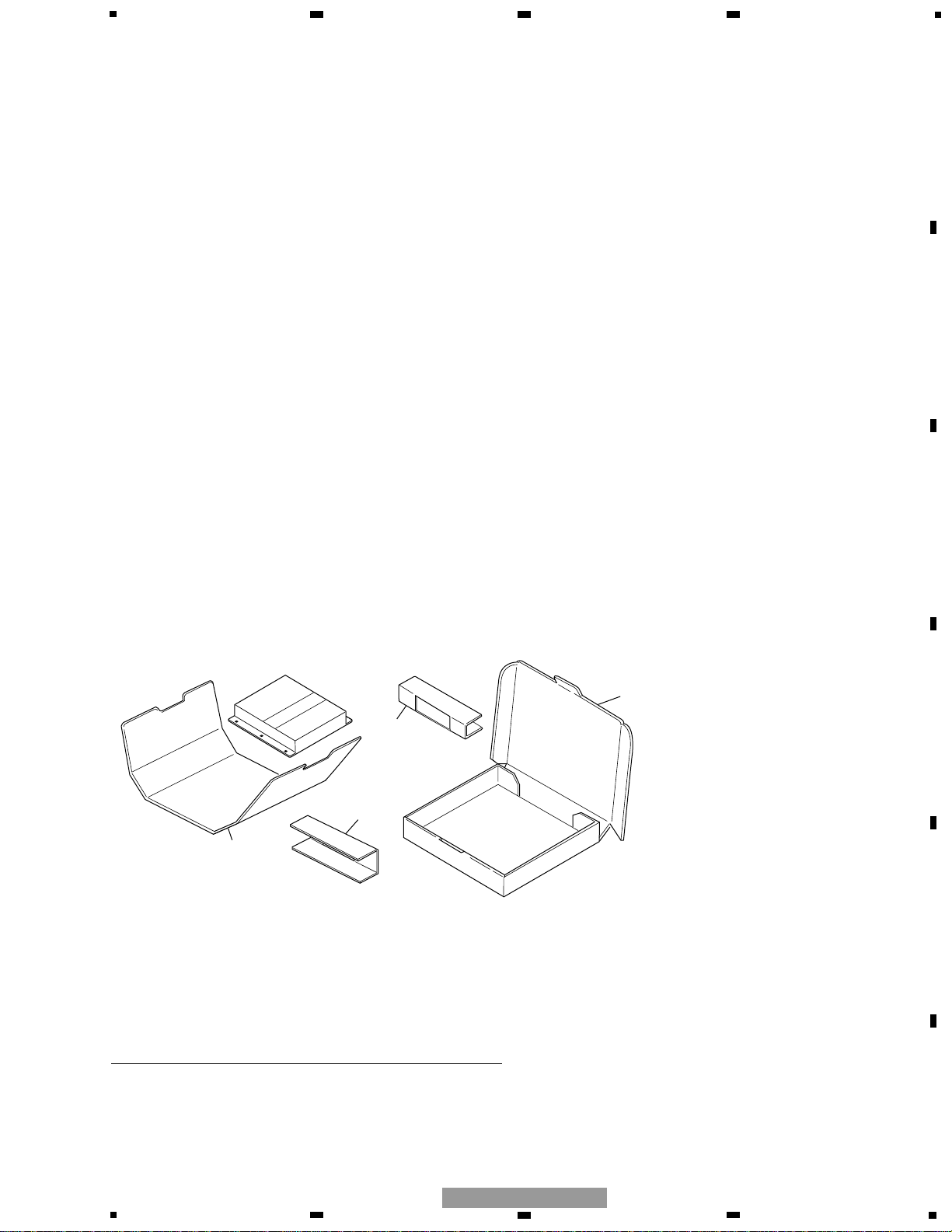
2.1 PACKING
1 Carton HHG0438
2 Pad HHW0052
3 Pad HHW0051
NOTE:
- Parts marked by “*” are generally unavailable because they are not in our Master Spare Parts List.
- Screws adjacent to ∇ mark on the product are used for disassembly.
- For the applying amount of lubricants or glue, follow the instructions in this manual.
( In the case of no amount instructions, apply as you think it appropriate.)
- PACKING SECTION PARTS LIST
Mark No. Description Part No.
1
2
2
3
Page 4
4
1
234
12
34
F
E
D
C
B
A
GM-2137ZF/X1R/UC
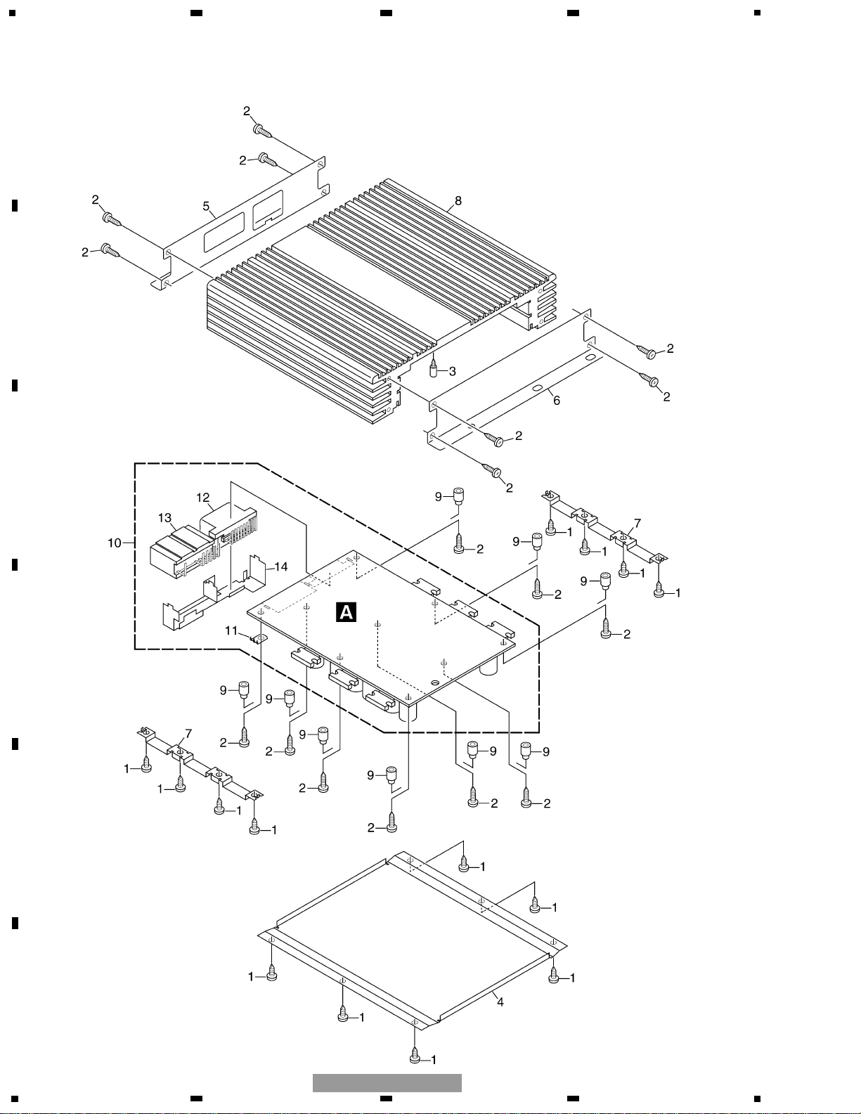
2.2 EXTERIOR
Page 5

5
5
6
7
8
F
E
D
C
B
A
5
6
7
8
GM-2137ZF/X1R/UC
1 Screw BBZ30P060FTC
2 Screw(M3x12) HBA0027
3 Screw(M3x5) HBA0028
4 Case HNB0200
5 Panel HNB0201
6 Panel HNB0202
7 Holder HNC0140
8 Heat Sink HNR0225
9 Spacer HNV0016
10 Amp Unit HWM0101
11 Terminal(CN103) CKF1059
12 Connector(CN102) HKE0040
13 Connector(CN101) HKM0004
14 Holder HNC0141
- EXTERIOR SECTION PARTS LIST
Mark No. Description Part No.
Page 6
6
1
234
12
34
F
E
D
C
B
A
GM-2137ZF/X1R/UC
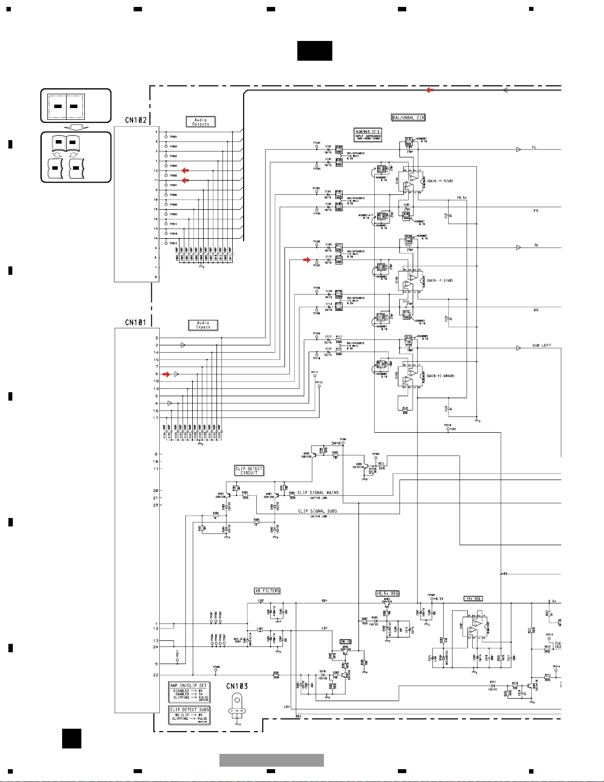
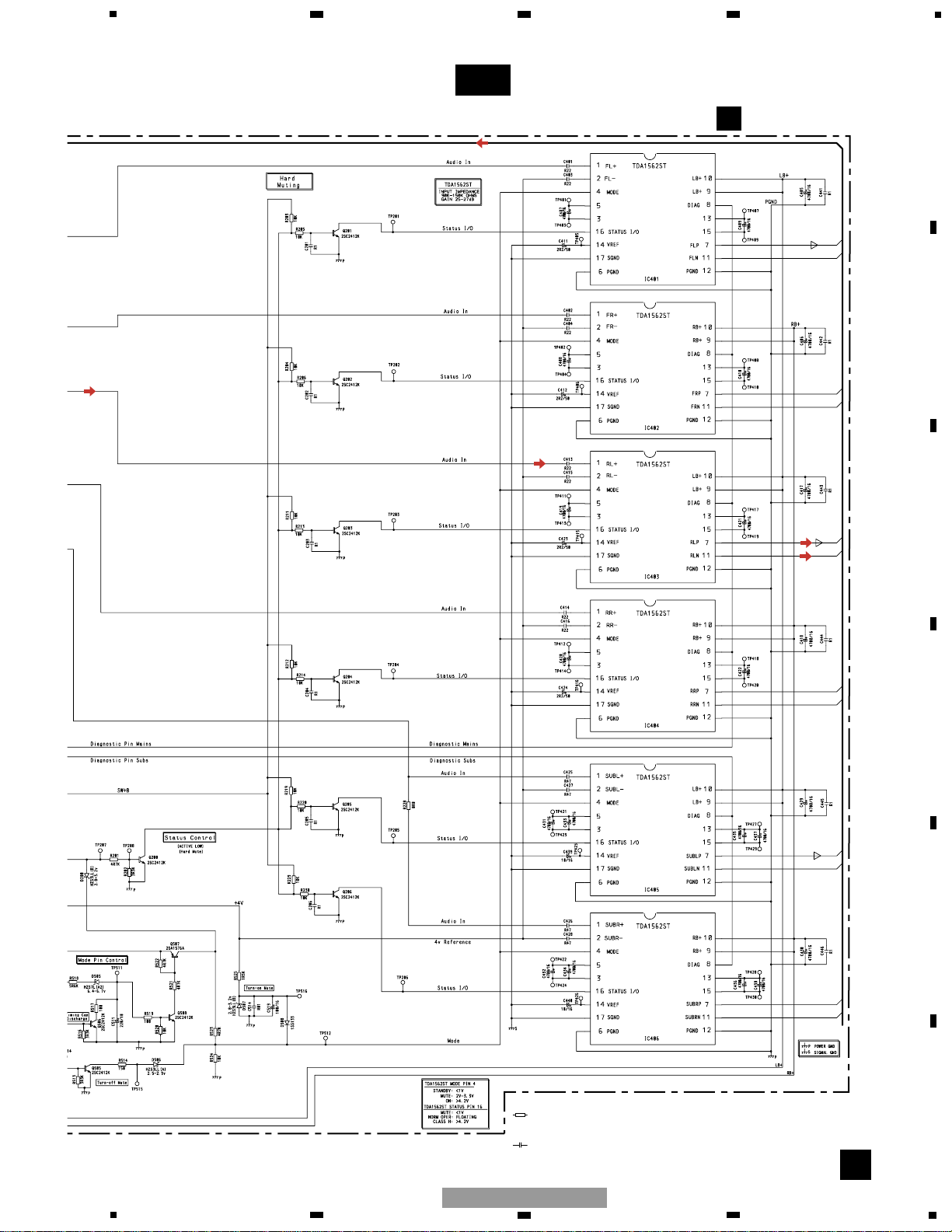
3. SCHEMATIC DIAGRAM
3.1 SCHEMATIC DIAGRAM (GUIDE PAGE)
A-aA-a A-b A-b
A-aA-a
A-b A-b
A-b A-b
A-a A-a
Large size
SCH diagram
Guide page
Detailed page
Note: When ordering service parts, be sure to refer to " EXPLODED VIEWS AND PARTS LIST" or
"ELECTRICAL PARTS LIST".
A-a
A
FLFL+
FR-
FR+
RL-
RL+
RR-
RR+
SUB LSUB L+
SUB R-
SUB R+
FL-
FL+
FR+
FR-
RLRL+
RR+
RR-
SUB LSUB L+
SUB R+
SUB R-
+B
POWER GND
Subwoofer
Clip Detect
AMP Enable
/ Clip Detect
Page 7
7
5
6
7
8
F
E
D
C
B
A
5
6
7
8
GM-2137ZF/X1R/UC
A-b
A
Decimal points for resistor
and capacitor fixed values
are expressed as :
2.2 2R2
0.022 R022
←
←
Symbol indicates a resistor.
No differentiation is made between chip resistors and
discrete resistors.
NOTE :
Symbol indicates a capacitor.
No differentiation is made between chip capacitors and
discrete capacitors.
A
AMP UNIT
Page 8

8
1
234
12
34
F
E
D
C
B
A
GM-2137ZF/X1R/UC
A-a
A-b
A-a
A-a
A-b
1
2
3
FL-
FL+
FR-
FR+
RL-
RL+
RR-
RR+
SUB L-
SUB L+
SUB R-
SUB R+
FL-
FL+
FR+
FR-
RL-
RL+
RR+
RR-
SUB L-
SUB L+
SUB R+
Page 9

9
5
6
7
8
F
E
D
C
B
A
5
6
7
8
GM-2137ZF/X1R/UC
A-a
A-b
A-a
A-a
A-b
4 5 6 7
SUB L-
SUB L+
SUB R+
SUB R-
+B
POWER GND
Subwoofer
Clip Detect
AMP Enable
/ Clip Detect
Page 10

10
1
234
12
34
F
E
D
C
B
A
GM-2137ZF/X1R/UC
A-a
A-b
A-b
1
2
3
A
AMP UNIT
Page 11

11
5
6
7
8
F
E
D
C
B
A
5
6
7
8
GM-2137ZF/X1R/UC
A-a
A-b
A-b
4 5 6 7
Decimal points for resistor
and capacitor fixed values
are expressed as :
2.2 2R2
0.022 R022
←
←
Symbol indicates a resistor.
No differentiation is made between chip resistors and
discrete resistors.
NOTE :
Symbol indicates a capacitor.
No differentiation is made between chip capacitors and
discrete capacitors.
Page 12

12
1
234
12
34
F
E
D
C
B
A
GM-2137ZF/X1R/UC
4. PCB CONNECTION DIAGRAM
4.1 AMP UNIT
Capacitor
Connector
P.C.Board
Chip Part
A
A
AMP UNIT
SIDE B
SIDE A
NOTE FOR PCB DIAGRAMS
1.The parts mounted on this PCB
include all necessary parts for
several destination.
For further information for
respective destinations, be sure
to check with the schematic dia gram.
2.Viewpoint of PCB diagrams
1
13
2
14
3
15
4
16
5
17
6
18
7
19
8
20
21
9
22
10
23
11
24
12
1
9
2
10
3
11
4
12
5
13
614
7
15
8
16
FRO
Page 13

13
5
6
7
8
F
E
D
C
B
A
5
6
7
8
GM-2137ZF/X1R/UC
A
SIDE A
FRONT
Page 14

14
1
234
12
34
F
E
D
C
B
A
GM-2137ZF/X1R/UC
A
A
AMP UNIT
Page 15

15
5
6
7
8
F
E
D
C
B
A
5
6
7
8
GM-2137ZF/X1R/UC
A
SIDE B
1
1
Page 16

Unit Number : HWM0101
Unit Name : Amp Unit
MISCELLANEOUS
IC 101 IC NJM2068V
IC 102 IC NJM2068V
IC 103 IC NJM2068V
IC 401 IC TDA1562ST
IC 402 IC TDA1562ST
IC 403 IC TDA1562ST
IC 404 IC TDA1562ST
IC 405 IC TDA1562ST
IC 406 IC TDA1562ST
IC 501 IC NJM4558V
Q 200 Transistor 2SC2412K
Q 201 Transistor 2SC2412K
Q 202 Transistor 2SC2412K
Q 203 Transistor 2SC2412K
Q 204 Transistor 2SC2412K
Q 205 Transistor 2SC2412K
Q 206 Transistor 2SC2412K
Q 301 Transistor 2SB1238
Q 302 Transistor 2SB1238
Q 303 Transistor 2SB1238
Q 304 Transistor 2SC2412K
Q 501 Transistor 2SC2458
Q 502 Transistor 2SB1238
Q 503 Transistor 2SD1859
Q 504 Transistor 2SC2412K
Q 505 Transistor 2SC2412K
Q 506 Transistor 2SC2412K
Q 507 Transistor 2SA1576A
Q 508 Transistor 2SC2412K
D 200 Diode HZS3LL(B)
D 301 Diode 1SS133
D 302 Diode 1SS133
D 303 Diode 1SS133
D 304 Diode 1SS133
D 501 Diode RM4Z-LFJ4
D 502 Diode 1SS133
D 503 Diode MTZJ9R1(C)
D 504 Diode MTZJ4R3(C)
D 505 Diode HZS7L(A2)
D 506 Diode HZS3LL(A)
D 507 Diode HZS3LL(B)
D 508 Diode 1SS133
D 509 Diode 1SS133
D 510 Diode 1SS133
D 511 Diode 1SS133
L 501 Choke Coil 0.3mH HTH0001
L 502 Choke Coil 0.3mH HTH0001
RESISTORS
R 101 5.6kΩ HCN0007
R 102 RN1/4PC6801D
R 103 RN1/4PC6801D
R 104 RN1/4PC6801D
R 105 RN1/4PC6801D
R 106 5.6kΩ HCN0007
R 107 5.6kΩ HCN0007
R 108 5.6kΩ HCN0007
R 109 5.6kΩ HCN0007
R 110 RN1/4PC6801D
R 111 RN1/4PC6801D
R 112 RN1/4PC6801D
R 113 RN1/4PC6801D
R 114 5.6kΩ HCN0007
R 115 5.6kΩ HCN0007
R 116 5.6kΩ HCN0007
R 117 RN1/4PC6801D
R 118 15kΩ HCN0009
R 119 RN1/4PC6801D
R 120 15kΩ HCN0009
R 124 RS1/16S0R0J
R 201 RS1/16S472J
R 202 RS1/16S332J
R 203 RS1/16S103J
R 204 RS1/16S103J
R 205 RS1/16S103J
R 206 RS1/16S103J
R 211 RS1/16S103J
R 212 RS1/16S103J
R 213 RS1/16S103J
R 214 RS1/16S103J
R 219 RS1/16S103J
R 220 RS1/16S103J
R 228 RS1/16S0R0J
R 229 RS1/16S103J
R 230 RS1/16S103J
R 301 RS1/16S103J
R 302 RS1/16S222J
R 303 RS1/16S102J
R 304 RS1/16S103J
R 305 RS1/16S222J
R 306 RS1/16S102J
R 307 RS1/16S103J
R 308 RS1/16S332J
R 309 RS1/16S103J
R 310 RS1/16S332J
R 311 RS1/16S472J
R 501 RS1/16S332J
R 502 RS1/16S222J
R 503 RS1/16S331J
R 504 RS1/16S472J
R 505 RS1/16S472J
R 506 RS1/16S103J
R 507 RS1/16S122J
R 508 RS1/16S101J
16
1
234
12
34
F
E
D
C
B
A
GM-2137ZF/X1R/UC
5. ELECTRICAL PARTS LIST
NOTE:
- Parts whose parts numbers are omitted are subject to being not supplied.
- The part numbers shown below indicate chip components.
Chip Resistor
RS1/_S___J,RS1/__S___J
Chip Capacitor (except for CQS.....)
CKS....., CCS....., CSZS.....
=====Circuit Symbol and No.===Part Name Part No.
--- ------ ------------------------------------------ -------------------------
=====Circuit Symbol and No.===Part Name Part No.
--- ------ ------------------------------------------ -------------------------
A
Page 17

17
5
6
7
8
F
E
D
C
B
A
5
6
7
8
GM-2137ZF/X1R/UC
=====Circuit Symbol and No.===Part Name Part No.
--- ------ ------------------------------------------ -------------------------
=====Circuit Symbol and No.===Part Name Part No.
--- ------ ------------------------------------------ -------------------------
R 509 RS1/16S471J
R 510 RS1/16S331J
R 511 RS1/16S472J
R 512 RS1/16S222J
R 513 RS1/16S332J
R 514 RS1/16S151J
R 515 RS1/16S222J
R 516 RS1/16S332J
R 517 RS1/16S101J
R 518 RS1/16S562J
R 519 RS1/16S101J
R 520 RS1/16S103J
R 521 RS1/16S472J
R 522 RS1/16S472J
R 523 RS1/16S472J
R 524 RS1/16S103J
R 525 RS1/16S152J
R 526 RS1/16S472J
R 527 RS1/16S102J
R 555 RS1/16S222J
CAPACITORS
C 1 CCSRCH101J50
C 2 CCSRCH101J50
C 3 CCSRCH101J50
C 4 CCSRCH101J50
C 5 CCSRCH101J50
C 6 CCSRCH101J50
C 7 CCSRCH101J50
C 8 CCSRCH101J50
C 9 CCSRCH101J50
C 10 CCSRCH101J50
C 11 CCSRCH101J50
C 12 CCSRCH101J50
C 101 CEJQ100M16
C 102 CEJQ100M16
C 103 CKSRYB271K50
C 104 CEJQ100M16
C 105 CEJQ100M16
C 106 CKSRYB271K50
C 107 CKSRYB271K50
C 108 CKSRYB271K50
C 109 CEJQ100M16
C 110 CEJQ100M16
C 111 CKSRYB271K50
C 112 CEJQ100M16
C 113 CEJQ100M16
C 114 CKSRYB271K50
C 115 CKSRYB271K50
C 116 CKSRYB271K50
C 117 CEJQ220M16
C 118 CCSRCH101J50
C 119 CEJQ220M16
C 120 CCSRCH101J50
C 121 CKSRYB104K25
C 122 CKSRYB104K25
C 123 CKSRYB104K25
C 124 CCSRCH101J50
C 125 CCSRCH101J50
C 126 CCSRCH101J50
C 127 CCSRCH101J50
C 128 CCSRCH101J50
C 129 CCSRCH101J50
C 130 CCSRCH101J50
C 131 CCSRCH101J50
C 132 CCSRCH101J50
C 133 CCSRCH101J50
C 134 CCSRCH101J50
C 135 CCSRCH101J50
C 201 CKSRYB104K25
C 202 CKSRYB104K25
C 203 CKSRYB104K25
C 204 CKSRYB104K25
C 205 CKSRYB104K25
C 206 CKSRYB104K25
C 401 CFTLA224J50
C 402 CFTLA224J50
C 403 CFTLA224J50
C 404 CFTLA224J50
C 405 4700µF/16V HCH0009
C 406 4700µF/16V HCH0009
C 407 4700µF/16V HCH0009
C 408 4700µF/16V HCH0009
C 409 4700µF/16V HCH0009
C 410 4700µF/16V HCH0009
C 411 CEJQ2R2M50
C 412 CEJQ2R2M50
C 413 CFTLA224J50
C 414 CFTLA224J50
C 415 CFTLA224J50
C 416 CFTLA224J50
C 417 4700µF/16V HCH0009
C 418 4700µF/16V HCH0009
C 419 4700µF/16V HCH0009
C 420 4700µF/16V HCH0009
C 421 4700µF/16V HCH0009
C 422 4700µF/16V HCH0009
C 423 CEJQ2R2M50
C 424 CEJQ2R2M50
C 425 CFTLA474J50
C 426 CFTLA474J50
C 427 CFTLA474J50
C 428 CFTLA474J50
C 429 4700µF/16V HCH0009
C 430 4700µF/16V HCH0009
C 431 4700µF/16V HCH0009
C 432 4700µF/16V HCH0009
C 433 4700µF/16V HCH0009
C 434 4700µF/16V HCH0009
C 435 4700µF/16V HCH0009
C 436 4700µF/16V HCH0009
C 437 4700µF/16V HCH0009
C 438 4700µF/16V HCH0009
C 439 CEJQ100M16
C 440 CEJQ100M16
C 441 CKSRYB104K25
C 442 CKSRYB104K25
C 443 CKSRYB104K25
C 444 CKSRYB104K25
C 445 CKSRYB104K25
C 446 CKSRYB104K25
C 501 4700µF/16V HCH0009
C 502 CKCYF103Z50
C 503 4700µF/16V HCH0009
C 504 CKCYF103Z50
C 505 CKCYF103Z50
C 506 CKSRYB103K50
C 507 CEAT331M16
C 508 CKSRYB103K50
C 509 CEJQ100M16
C 510 CKSRYB102K50
C 511 CEJQ221M10
C 514 CKSRYB103K50
C 515 CEJQ220M16
C 516 CEJQ1R0M50
C 517 CKSRYB102K50
C 518 CKSRYB104K25
C 519 CEJQ101M16
Page 18

18
1
234
12
34
F
E
D
C
B
A
GM-2137ZF/X1R/UC
6. ADJUSTMENT
There is no information to be shown in this chapter.
7. GENERAL INFORMATION
7.1 DIAGNOSIS
7.1.1 DISASSEMBLY
1
1
- Removing the Case (Fig.1)
- Removing the Amp Unit (Fig.2)
Remove the six screws and then remove
the Case.
Remove the four screws and then
remove the Panel.
Fig.1
Fig.2
Holder
Case
Amp Unit
2
Remove the eight screws and then
remove the two Holders.
Panel
Holder
3
Remove the nine screws and then
remove the Amp Unit.
1
1
1
1 1
1
1
1
1
1
2
2
2
2
2
2
2
2
3
3
3
3 3
3
3
3
3
Page 19

19
5
6
7
8
F
E
D
C
B
A
5
6
7
8
GM-2137ZF/X1R/UC
7.1.2 CONNECTOR FUNCTION DESCRIPTION
12
24
11
16 15 14 13 12 11 10 9
8 7 6 5 4 3 2 1
23
10
22
21
9
8
20
19
18
7
6
17
15
16
14
3
5
4
13
2
1
1. FR+
2. FR-
3. FL+
4. FL-
5. NC
6. NC
7. NC
8. NC
9. RR-
10. RR+
11. RL+
12. RL-
13. SUB R-
14. SUB R+
15. SUB L-
16. SUB L+
1. +B
2. FL+
3. FL-
4. SUB L+
5. SUB L-
6. RL+
7. RL-
8. NC
9. Subwoofer Clip Detect
10. NC
11. NC
12. POWER GND
13. +B
14. FR+
15. FR-
16. SUB R+
17. SUB R-
18. RR+
19. RR-
20. NC
21. NC
22. AMP Enable/Clip Detect
23. NC
24. POWER GND
Page 20

20
1
234
12
34
F
E
D
C
B
A
GM-2137ZF/X1R/UC
7.2 IC
IN+
IN-
C1-
MODE
C1+
PGND1
OUT+
DIAG
VP1
VP2
OUT-
PGND2
C2+
VREF
C2-
STAT
SGND
1
2
3
4
5
6
7
8
9
10
11
12
13
14
15
16
17
POWER-
STAGE
POWER-
STAGE
PREAMP
+
-
FEEDBACK
CIRCUIT
PREAMP
+
-
LOAD
DETECTOR
DYNAMIC
DISTORTION
DETECTOR
DIAGNOSTIC
INTERFACE
CURRENT
PROTECTION
LOAD DUMP
PROTECTION
TEMPERATURE
PROTECTION
LIFT-SUPPLY
LIFT-SUPPLY
TEMPERATURE
SENSOR
CLASS-B
CLASS-H
FAST MUTE
STANDBY
MUTE
ON
reference
voltage
disable
disable
Vp*
Vp*
1
2
4
3
5
9
16
10
7
8
15
11
17
14
TDA1562ST
Page 21

21
5
6
7
8
F
E
D
C
B
A
5
6
7
8
GM-2137ZF/X1R/UC
7.3 SYSTEM BLOCK DIAGRAM
GPS Antenna
Denso
Navigation software
HMI software
Navigation ECU
GPS Receiver
Gyro sensor
Voice recognition
DVD-ROM
TVM
4 button
Command
Amplifier Unit
Pioneer
6.5inch TFT Display
AM/FM Antenna
6ch Output
Audio Signals( Voice)
Video Signals (RGB)
Touch Panel for Navi
6 Disc CD Player
AM/FM/RBDS Tuner
DSP
SIRIUS Satellite
Radio System
SCP-BUS
CAN(MCNET)
ACP-BUS
Rear Seat
Controller
System
Entertainment
Rear Seat DVD
SWCSWC
Page 22

22
1
234
12
34
F
E
D
C
B
A
GM-2137ZF/X1R/UC
8. OPERATIONS
There is no information to be shown in this chapter.
 Loading...