

Page 1
PIONEER CORPORATION
4-1, Meguro 1-Chome, Meguro-ku, Tokyo 153-8654, Japan
PIONEER ELECTRONICS (USA) INC. P.O.Box 1760, Long Beach, CA 90801-1760 U.S.A.
PIONEER EUROPE NV Haven 1087 Keetberglaan 1, 9120 Melsele, Belgium
PIONEER ELECTRONICS ASIACENTRE PTE.LTD. 253 Alexandra Road, #04-01, Singapore 159936
C PIONEER CORPORATION 2002
K-ZZB. JUNE 2002 Printed in Japan
AMPLIFIER
GM-2027
ZF
X1R/UC
VEHICLE DESTINATION PRODUCED AFTER PART No. ID No. PIONEER MODEL No.
LINCOLN U.S.A., CANADA 2003 GM-2027ZF/X1R/UC
For details, refer to "Important symbols for good services".
ORDER NO.
CRT2866
FORD
GM-2027ZF/X1R/UC
Page 2
2
1
234
12
34
F
E
D
C
B
A
GM-2027ZF/X1R/UC
SAFETY INFORMATION
This service manual is intended for qualified service technicians; it is not meant for the casual do-it-yourselfer.
Qualified technicians have the necessary test equipment and tools, and have been trained to properly and safely repair
complex products such as those covered by this manual.
Improperly performed repairs can adversely affect the safety and reliability of the product and may void the warranty.
If you are not qualified to perform the repair of this product properly and safely, you should not risk trying to do so
and refer the repair to a qualified service technician.
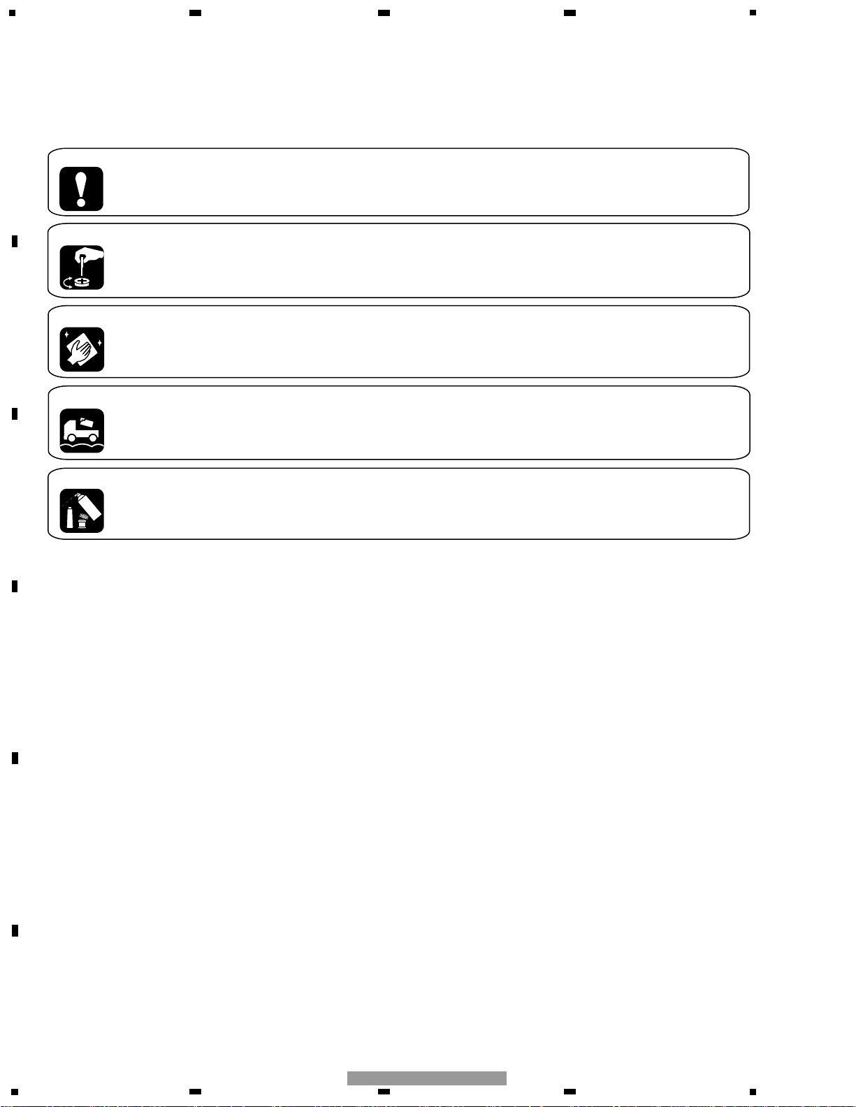
[ Important symbols for good services ]
In this manual, the symbols shown-below indicate that adjustments, settings or cleaning should be made securely.
When you find the procedures bearing any of the symbols, be sure to fulfill them:
2. Adjustments
To keep the original performances of the product, optimum adjustments or specification confirmation is indispensable.
In accordance with the procedures or instructions described in this manual, adjustments should be performed.
3. Cleaning
For optical pickups, tape-deck heads, lenses and mirrors used in projection monitors, and other parts requiring cleaning,
proper cleaning should be performed to restore their performances.
5. Lubricants, glues, and replacement parts
Appropriately applying grease or glue can maintain the product performances. But improper lubrication or applying
glue may lead to failures or troubles in the product. By following the instructions in this manual, be sure to apply the
prescribed grease or glue to proper portions by the appropriate amount.For replacement parts or tools, the prescribed
ones should be used.
4. Shipping mode and shipping screws
To protect the product from damages or failures that may be caused during transit, the shipping mode should be set or
the shipping screws should be installed before shipping out in accordance with this manual, if necessary.
1. Product safety
You should conform to the regulations governing the product (safety, radio and noise, and other regulations), and
should keep the safety during servicing by following the safety instructions described in this manual.
CONTENTS
SAFETY INFORMATION ............................................2
1. SPECIFICATIONS........................................................2
2. EXPLODED VIEWS AND PARTS LIST.......................3
3. SCHEMATIC DIAGRAM .............................................4
4. PCB CONNECTION DIAGRAM ................................10
5. ELECTRICAL PARTS LIST ........................................14
6. ADJUSTMENT..........................................................16
7. GENERAL INFORMATION .......................................16
7.1 DIAGNOSIS ........................................................16
7.1.1 DISASSEMBLY .........................................16
7.1.2
CONNECTOR FUNCTION DESCRIPTION.......17
1. SPECIFICATIONS
Power source .........14.4±0.2V(10.5V-16.0V allowable) DC
Grounding system........................................Negative type
Backup current..............................................0.5mA or less
Dimensions.......................173.3(W)x51.7(H)x151.7(D)mm
Weight..........................................................................1.1kg
Page 3
3
5
6
7
8
F
E
D
C
B
A
5
6
7
8
GM-2027ZF/X1R/UC
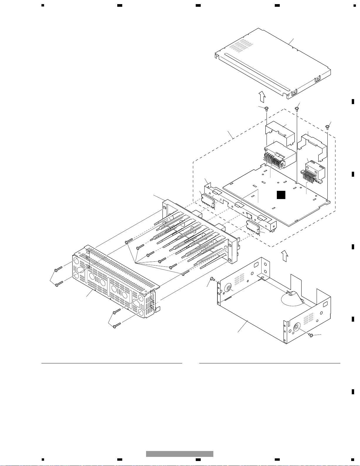
2. EXPLODED VIEWS AND PARTS LIST
2.1 EXTERIOR
1 Screw BMZ26P180FMC
2 Screw BMZ30P050FMC
3 Chassis HNA0004
4 Case HNB0151
5 Shield HNC0126
6 Heat Sink HNR0190
7 Mother Unit HWM0071
8 Connector(CN102) HKE0040
9 Connector(CN101) HKM1349
10 Holder HNC0104
11 Holder HNC0105
12 Holder HNC0106
13 Screw IMS30P050FMC
14 IC(IC401) PAL006A
15 IC(IC403) PAL006A
- EXTERIOR SECTION PARTS LIST
Mark No. Description Part No.
Mark No. Description Part No.
4
13
13
11
7
12
9
13
8
10
15
6
A
1
1
5
1
14
2
3
2
Page 4
4
1
234
12
34
F
E
D
C
B
A
GM-2027ZF/X1R/UC
A-a A-b
A-a
A-b
A-b
A-a
Large size
SCH diagram
Guide page
Detailed page
Note: When ordering service parts, be sure to refer to " EXPLODED VIEWS AND PARTS LIST" or
"ELECTRICAL PARTS LIST".
A-a
A
0.3mH
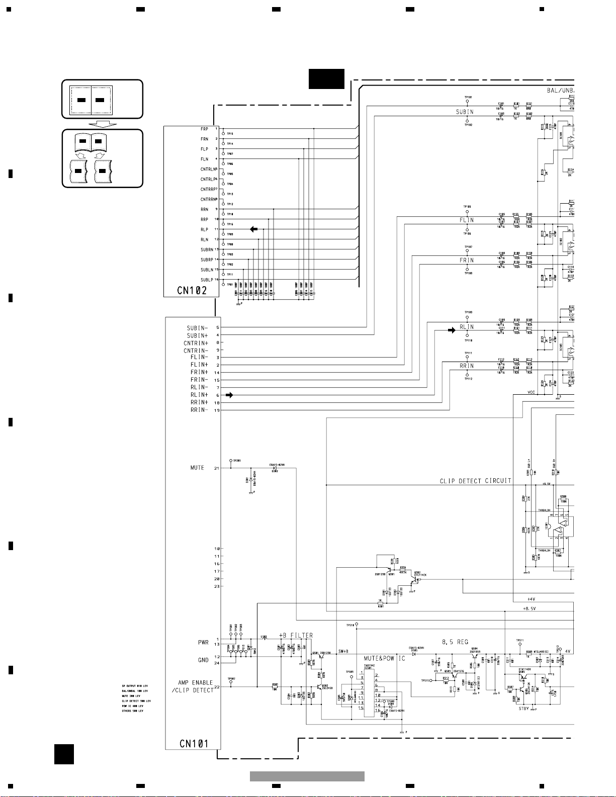
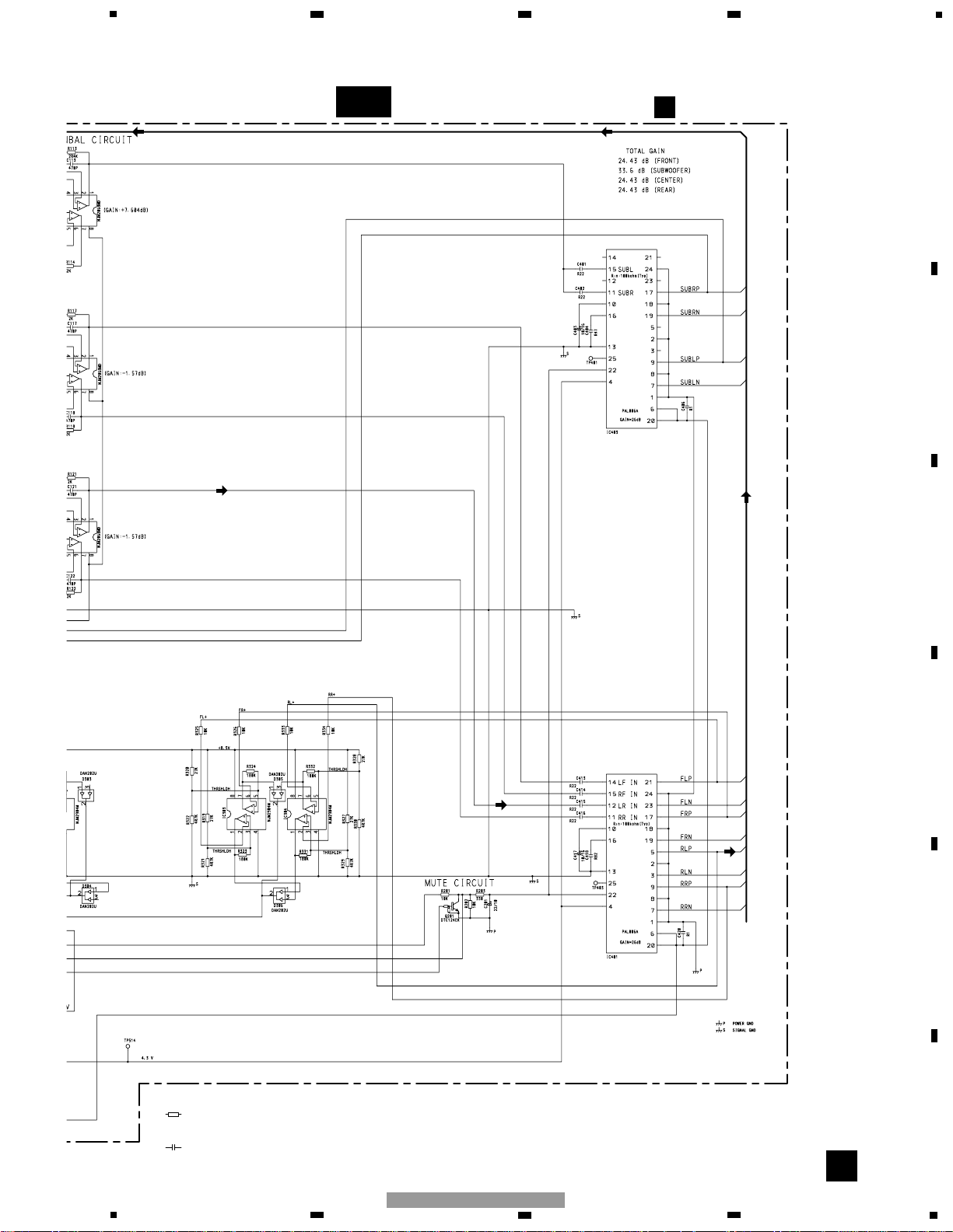
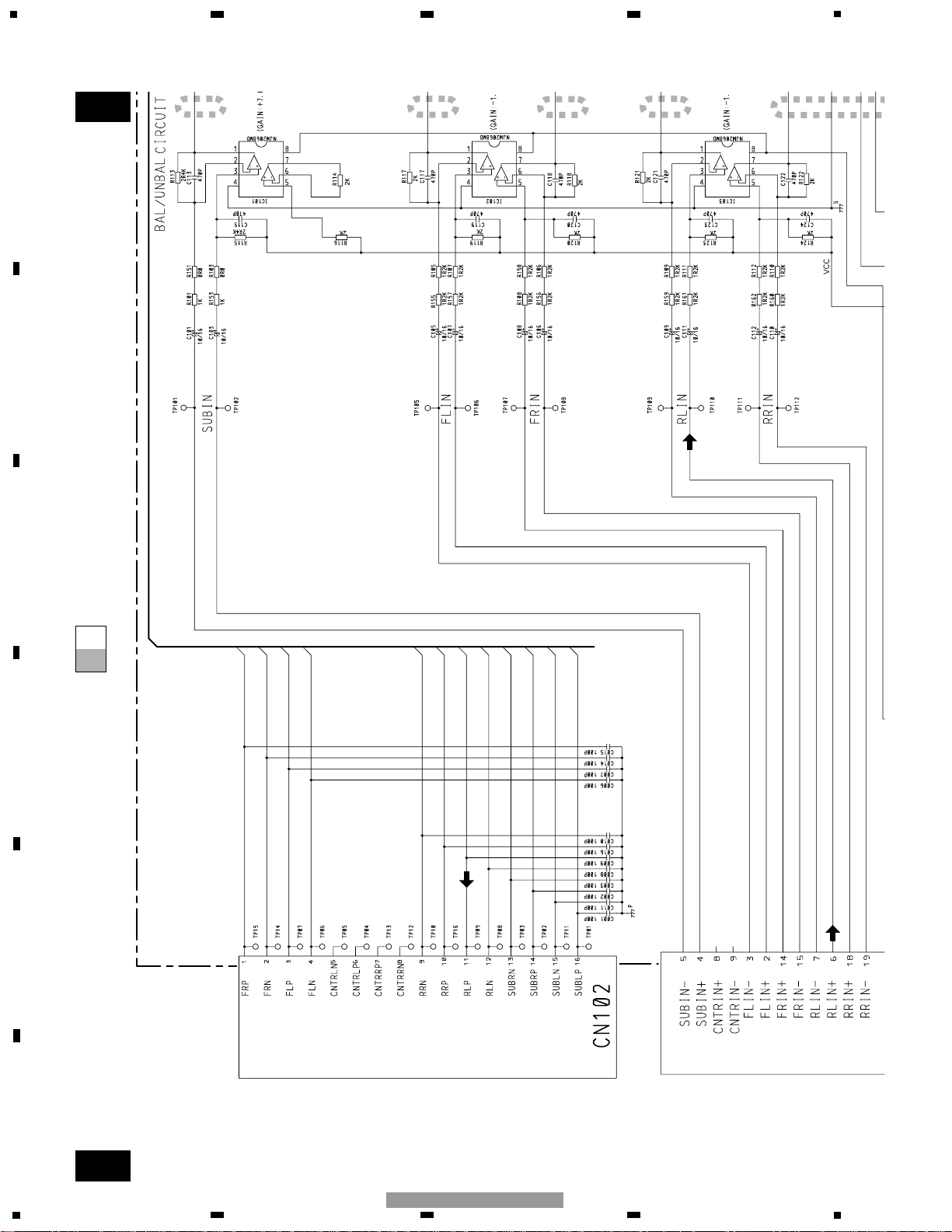
3. SCHEMATIC DIAGRAM
3.1 OVERALL CONNECTION DIAGRAM(GUIDE PAGE)
Page 5
5
5
6
7
8
F
E
D
C
B
A
5
6
7
8
GM-2027ZF/X1R/UC
A-b
A
Decimal points for resistor
and capacitor fixed values
are expressed as :
2.2 2R2
0.022 R022
←
←
Symbol indicates a resistor.
No differentiation is made between chip resistors and
discrete resistors.
NOTE :
Symbol indicates a capacitor.
No differentiation is made between chip capacitors and
discrete capacitors.
A
MOTHER UNIT
Page 6
6
1
234
12
34
F
E
D
C
B
A
GM-2027ZF/X1R/UC
A-a
A-b
A-a
A-a
A-b
1
2
3
4
5
Page 7

7
5
6
7
8
F
E
D
C
B
A
5
6
7
8
GM-2027ZF/X1R/UC
A-a
A-b
A-a
A-a
A-b
6
7
8 9
0.3mH
Page 8

8
1
234
12
34
F
E
D
C
B
A
GM-2027ZF/X1R/UC
A-a
A-b
A-b
1
2
3
4
5
A
MOTHER UNIT
Page 9

9
5
6
7
8
F
E
D
C
B
A
5
6
7
8
GM-2027ZF/X1R/UC
A-a
A-b
A-b
6
7
8 9
Decimal points for resistor
and capacitor fixed values
are expressed as :
2.2 2R2
0.022 R022
←
←
Symbol indicates a resistor.
No differentiation is made between chip resistors and
discrete resistors.
NOTE :
Symbol indicates a capacitor.
No differentiation is made between chip capacitors and
discrete capacitors.
Page 10

10
1
234
12
34
F
E
D
C
B
A
GM-2027ZF/X1R/UC
4. PCB CONNECTION DIAGRAM
4.1 MOTHER UNIT
Capacitor
Connector
P.C.Board
Chip Part
A
A
MOTHER UNIT
SIDE B
SIDE A
NOTE FOR PCB DIAGRAMS
1.The parts mounted on this PCB
include all necessary parts for
several destination.
For further information for
respective destinations, be sure
to check with the schematic dia gram.
2.Viewpoint of PCB diagrams
12
11 10 9 8
7
654
32
1
24
20
23 22 21
19
18 17 16
15 14
13
Page 11

11
5
6
7
8
F
E
D
C
B
A
5
6
7
8
GM-2027ZF/X1R/UC
A
SIDE A
2
1
14
13
86754321
161415 13 12 11
10
9
Page 12

12
1
234
12
34
F
E
D
C
B
A
GM-2027ZF/X1R/UC
A
A
MOTHER UNIT
1
Page 13

13
5
6
7
8
F
E
D
C
B
A
5
6
7
8
GM-2027ZF/X1R/UC
A
SIDE B
1
Page 14

14
1
234
12
34
F
E
D
C
B
A
GM-2027ZF/X1R/UC
5. ELECTRICAL PARTS LIST
NOTES:
- Parts whose parts numbers are omitted are subject to being not supplied.
- The part numbers shown below indicate chip components.
Chip Resistor
RS1/_S___J,RS1/__S___J
Chip Capacitor (except for CQS.....)
CKS....., CCS....., CSZS.....
=====Circuit Symbol and No.===Part Name Part No.
--- ------ ------------------------------------------ -------------------------
Unit Number : HWM0071
Unit Name : Mother Unit
MISCELLANEOUS
IC 101 IC NJM2068MD
IC 102 IC NJM2068MD
IC 103 IC NJM2068MD
IC 301 IC NJM2904M
IC 303 IC NJM2904M
IC 304 IC NJM2904M
IC 401 IC PAL006A
IC 403 IC PAL006A
IC 501 IC TA8194Z
Q 201 Transistor DTC124EK
Q 301 Transistor 2SB1238
Q 302 Transistor DTC114EK
Q 501 Transistor 2SB1238
Q 502 Transistor 2SC2458
Q 503 Transistor 2SA1576
Q 504 Transistor 2SD1859
Q 505 Transistor DTA114EK
Q 506 Transistor 2SC2412K
D 201 Diode ERA15-02VH
D 202 Diode ERA15-02VH
D 301 Diode 1SS133
D 302 Diode 1SS133
D 303 Diode DAN202U
D 304 Diode DAN202U
D 305 Diode DAN202U
D 306 Diode DAN202U
D 501 Diode RM4Z
D 502 Diode 1SS133
D 503 Diode MTZJ6R8(C)
D 504 Diode ERA15-02VH
D 505 Diode ERA15-02VH
D 506 Diode MTZ9R1(C)
D 507 Diode MTZJ4R3(C)
L 501 Choke Coil 0.3mH HTH0001
RESISTORS
R 101 RS1/10S102J
R 103 RS1/10S0R0J
R 105 RS1/10S122J
R 106 RS1/10S122J
R 107 RS1/10S122J
R 108 RS1/10S122J
R 109 RS1/10S122J
R 110 RS1/10S122J
R 111 RS1/10S122J
R 112 RS1/10S122J
R 113 RS1/16S242J
R 114 RS1/16S202J
R 115 RS1/16S242J
R 116 RS1/16S202J
R 117 RS1/16S202J
R 118 RS1/16S202J
R 119 RS1/16S202J
R 120 RS1/16S202J
R 121 RS1/16S202J
R 122 RS1/16S202J
R 123 RS1/16S202J
R 124 RS1/16S202J
R 151 RS1/10S0R0J
R 153 RS1/10S102J
R 155 RS1/10S122J
R 156 RS1/10S122J
R 157 RS1/10S122J
R 158 RS1/10S122J
R 159 RS1/10S122J
R 160 RS1/10S122J
R 161 RS1/10S122J
R 162 RS1/10S122J
R 201 RS1/16S103J
R 202 RS1/16S103J
R 203 RS1/16S331J
R 301 RD1/4PU102J
R 303 RS1/16S273J
R 304 RS1/16S273J
R 305 RS1/16S472J
R 306 RS1/16S472J
R 307 RS1/16S184J
R 308 RS1/16S184J
R 309 RS1/16S103J
R 310 RS1/16S103J
R 319 RS1/16S273J
R 320 RS1/16S273J
R 321 RS1/16S472J
R 322 RS1/16S472J
R 323 RS1/16S184J
R 324 RS1/16S184J
R 325 RS1/16S103J
R 326 RS1/16S103J
R 327 RS1/16S273J
R 328 RS1/16S273J
R 329 RS1/16S472J
R 330 RS1/16S472J
R 331 RS1/16S184J
R 332 RS1/16S184J
R 333 RS1/16S103J
R 334 RS1/16S103J
R 335 RS1/16S472J
R 336 RS1/16S472J
R 501 RD1/4PU103J
R 502 RS1/16S332J
R 503 RS1/16S472J
R 504 RS1/16S472J
R 505 RS1/16S102J
R 506 RS1/16S101J
R 507 RS1/16S103J
R 508 RS1/16S103J
=====Circuit Symbol and No.===Part Name Part No.
--- ------ ------------------------------------------ -------------------------
A
Page 15

15
5
6
7
8
F
E
D
C
B
A
5
6
7
8
GM-2027ZF/X1R/UC
R 509 RS1/16S102J
R 510 RS1/16S103J
R 512 RS1/16S103J
R 513 RS1/16S103J
R 514 RS1/16S103J
CAPACITORS
C 1 CCSRCH101J50
C 2 CCSRCH101J50
C 3 CCSRCH101J50
C 6 CCSRCH101J50
C 7 CCSRCH101J50
C 8 CCSRCH101J50
C 9 CCSRCH101J50
C 10 CCSRCH101J50
C 11 CCSRCH101J50
C 14 CCSRCH101J50
C 15 CCSRCH101J50
C 16 CCSRCH101J50
C 101 CEJQ100M16
C 103 CEJQ100M16
C 105 CEJQ100M16
C 106 CEJQ100M16
C 107 CEJQ100M16
C 108 CEJQ100M16
C 109 CEJQ100M16
C 110 CEJQ100M16
C 111 CEJQ100M16
C 112 CEJQ100M16
C 113 CCSRCH471J50
C 115 CCSRCH471J50
C 117 CCSRCH471J50
C 118 CCSRCH471J50
C 119 CCSRCH471J50
C 120 CCSRCH471J50
C 121 CCSRCH471J50
C 122 CCSRCH471J50
C 123 CCSRCH471J50
C 124 CCSRCH471J50
C 201 CEJQ220M10
C 401 CFTNA224J50
C 402 CFTNA224J50
C 403 CEJQ100M16
C 404 CFTNA474J50
C 406 CKSRYB104K25
C 413 CFTNA224J50
C 414 CFTNA224J50
C 415 CFTNA224J50
C 416 CFTNA224J50
C 417 CEJQ100M16
C 418 CFTLA824J50
C 420 CKSRYB104K25
C 501 4700µF/16V HCH0009
C 502 4700µF/16V HCH0009
C 503 CKCYF103Z50
C 504 CKCYF103Z50
C 505 CEJQ3R3M50
C 506 CEJQ101M16
C 507 CEAT331M16
C 508 CKSRYB103K50
C 509 CKSRYB103K50
C 510 CEAT331M16
C 511 CKSRYB103K50
C 513 CKSRYB103K50
C 514 CEJQ221M6R3
C 515 CEJQ1R0M50
=====Circuit Symbol and No.===Part Name Part No.
--- ------ ------------------------------------------ -------------------------
Page 16

16
1
234
12
34
F
E
D
C
B
A
GM-2027ZF/X1R/UC
7. GENERAL INFORMATION
7.1 DIAGNOSIS
7.1.1 DISASSEMBLY
6. ADJUSTMENT
There is no information to be shown in this chapter.
Fig.1
- Removing the Case (not shown)
Fig.2
Shield
Heat Sink
- Removing the Shield (Fig.1)
Remove the four screws and then
remove the Shield.
1
- Removing the Mother Unit (Fig.2)
Remove the three screws.
1
Remove the two screws and then
remove the Mother Unit.
2
1. Remove the Case.
- Removing the Heat Sink (Fig.1)
Remove the six screws and then
remove the Heat Sink.
2
1
1
1
1
2 2 2
222
Mother Unit
2
2
1
1
1
Page 17

17
5
6
7
8
F
E
D
C
B
A
5
6
7
8
GM-2027ZF/X1R/UC
7.1.2 CONNECTOR FUNCTION DESCRIPTION
C2 Right Angle type
LR Output +
15
RR Output -
14
16
8
9
13
12
11
7
6
5
4
3
2
1
10
NC
RF Output +
RF Output LF Output +
LF Output -
LR Output -
RR Output +
NC
Sub Speaker 2+
Sub Speaker 1Sub Speaker 1+
Sub Speaker 2-
NC
Pin No.
NC
Function
24
NC
20
19
NC
NC
Rear R Audio Input -
21
18
NC
NC
Rear R Audio Input +
16
17
14
13
Front R Audio Input -
Front R Audio Input +
Battery +
15
Amp Enable / CLD
Power GND
22
NC
NC8
9
11
7
6
5
4
3
2
1
10
Rear L Audio Input +
Battery +
Front L Audio Input +
Front L Audio InputSub Audio Input +
Power GND
Rear L Audio Input -
Pin No.
C1 Right angle type
Sub Audio Input -
NC
NC
12
Function
23
345
16
15
14 13
12 11 10 9
8
76 2
1
13
345
21222324
12 11 10 9 8
76 2
1
16171820 19 15 14
 Loading...