

Pioneer GEX-P5700TVP User Manual
MANUEL D’INSTALLATION
GEX-P5700TVP
INSTALLATION MANUAL
ENGLISH
ESPAÑOL
DEUTSCH
FRANÇAIS
ITALIANO
NEDERLANDS
This product conforms to new cord colors.
Los colores de los cables de este producto se conforman con un nuevo código de colores.
Dieses Produkt entspricht den neuen Kabelfarben.
Le code de couleur des câbles utilisé pour ce produit est
nouveau.
Questo prodotto è conforme ai nuovi codici colori.
De kleuren van de snoeren van dit toestel zijn gewijzigd.

1
Connecting the Units ................................ 1
Power cable connection .................................... 2
When using this unit as
“SRC : OSD OFF” mode .......................... 3
AV-BUS cable .................................................. 4
When using this unit as
“SRC : OSD ON” mode ............................ 4
When using this unit as
“STAND ALONE” mode .......................... 5
TV antenna connection ...................................... 6
Rear display connection .................................... 7
Installation .................................................. 8
Switching the operation mode............................ 8
Installing the unit .............................................. 8
Connecting the Units
Contents
Note:
• This unit is for vehicles with a 12-volt battery and
negative grounding. Before installing it in a recreational vehicle, truck, or bus, check the battery
voltage.
• To avoid shorts in the electrical system, be sure to
disconnect the (–) battery cable before beginning
installation.
• Refer to the owner’s manual for details on connecting the other units, then make connections
correctly.
• Secure the wiring with cable clamps or adhesive
tape. To protect the wiring, wrap adhesive tape
around them where they lie against metal parts.
• Route and secure all wiring so it cannot touch any
moving parts, such as the gear shift, handbrake
and seat rails. Do not route wiring in places that
get hot, such as near the heater outlet. If the insulation of the wiring melts or gets torn, there is a
danger of the wiring short-circuiting to the vehicle body.
• Don’t pass the yellow lead through a hole into the
engine compartment to connect to the battery.
This will damage the lead insulation and cause a
very dangerous short.
• Do not shorten any leads. If you do, the protection circuit may fail to work when it should.
• Never feed power to other equipment by cutting
the insulation of the power supply lead of the unit
and tapping into the lead. The current capacity of
the lead will be exceeded, causing over heating.
• When replacing fuse, be sure to only use fuse of
the rating prescribed on the fuse holder.
• To prevent incorrect connection, the input side of
the IP-BUS connector is blue, and the output side
is black. Connect the connectors of the same colors correctly.
• To minimize noise locate the TV antenna cable,
radio antenna cable and RCA cable as far away
from each other as possible.
• Cords for this product and those for other
products may be different colors even if they
have the same function. When connecting this
product to another product, refer to the supplied manuals of both products and connect
cords that have the same function.
2
ENGLISH ESPAÑOL DEUTSCH FRANÇAIS
ITALIANO NEDERLANDS
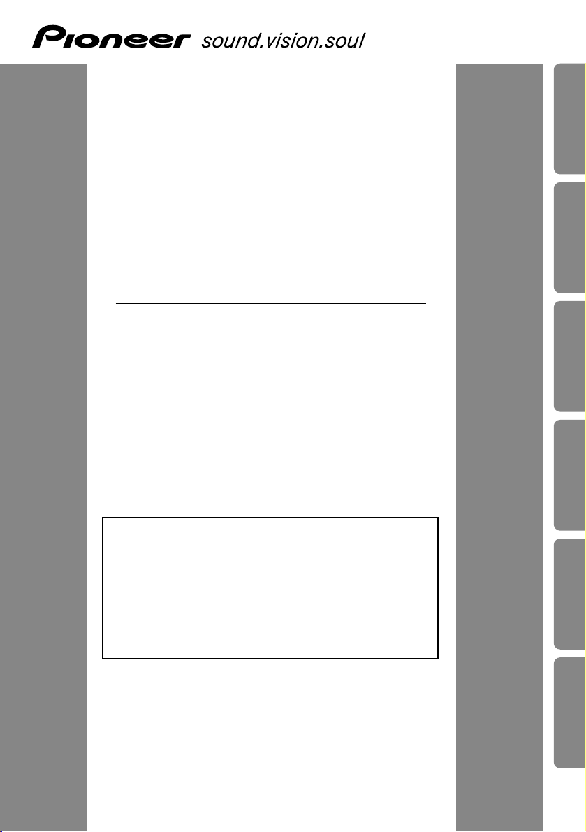
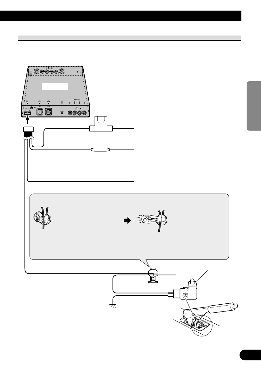
This unit
Fuse holder
Yellow
To terminal always supplied with power
regardless of ignition switch position.
Black (ground)
To vehicle (metal) body
Red
(Connect this lead only when this unit is
used as STAND ALONE mode.)
To electric terminal controlled by
ignition switch (12 V DC) ON/OFF.
Parking brake switch
Power supply side
Light green
Used to detect the ON/OFF status of
the parking brake. This lead must be
connected to the power supply side of
the parking brake switch.
Fuse resistor
Ground side
Connection method
1. Clamp the lead.
2. Clamp firmly with
needle-nosed pliers.
Note:
• The position of the parking brake switch depends
on the vehicle model. For details, consult the
vehicle Owner’s Manual or dealer.
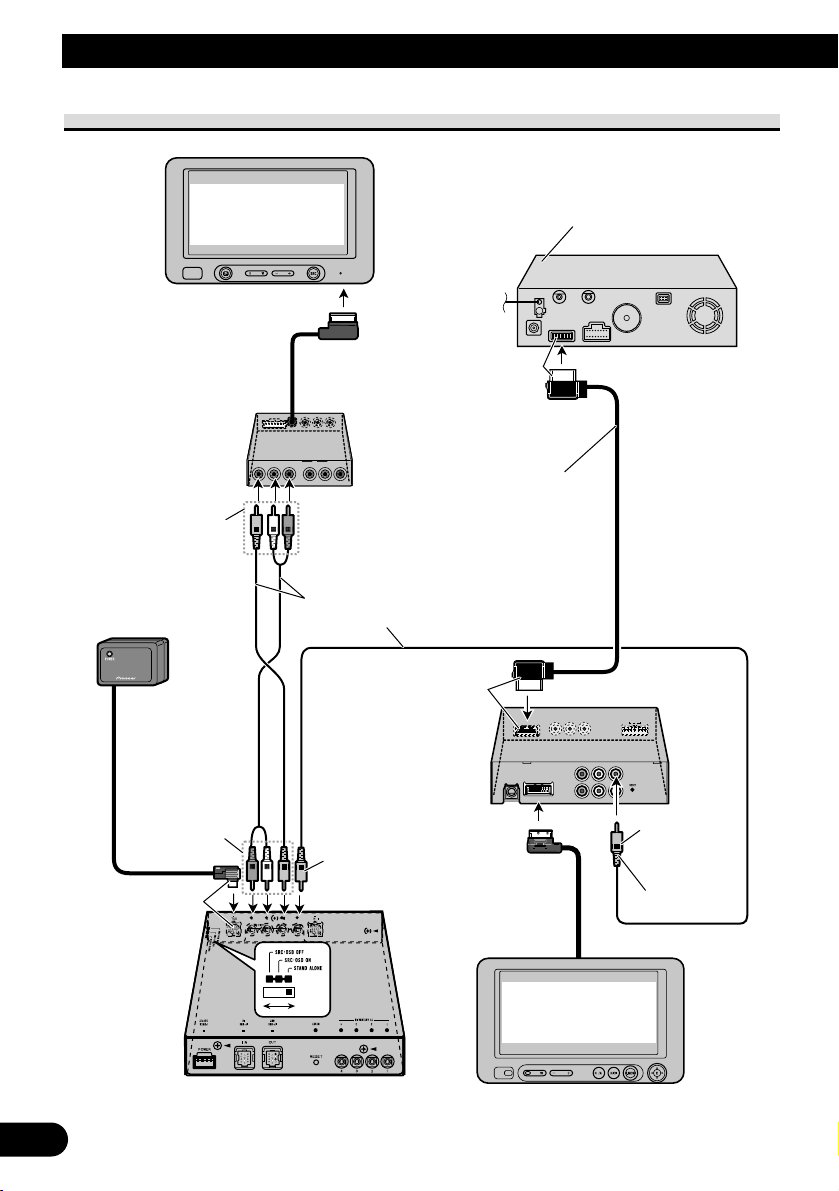
Power cable connection
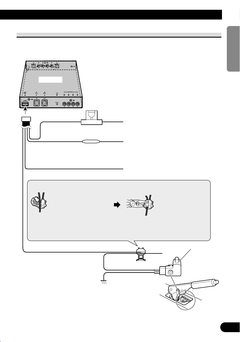
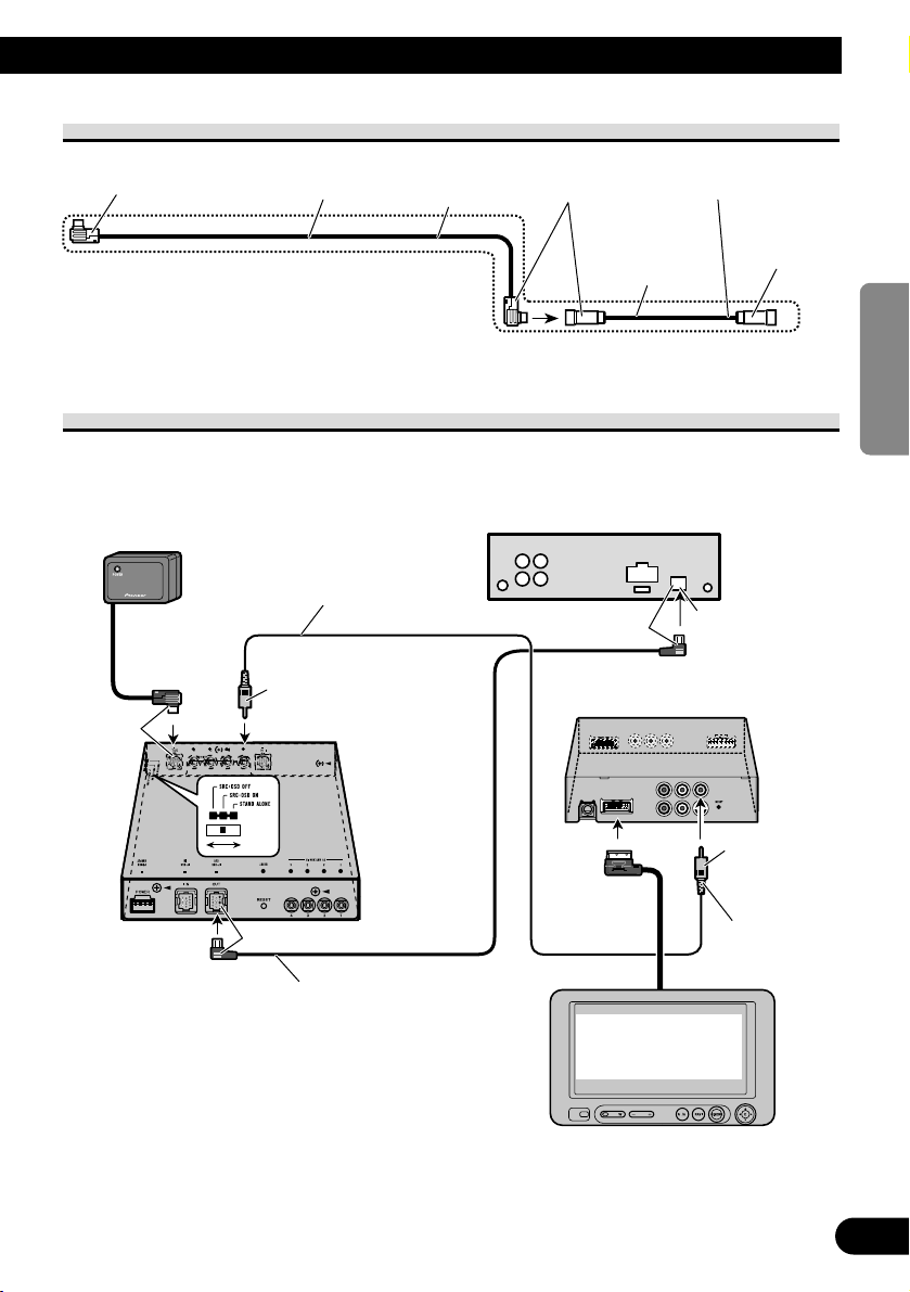
Blue
This unit
To video output
AV-BUS cable
(supplied)
AV receiver
(e.g. AVH-P5700DVD)
(sold separately)
26-pin cable
(supplied with Pioneer navigation unit)
(
RCA cable
supplied with
DVD player)
To video
1 input
To video 2
input
Blue
Black
Yellow
White/Red
3 m
3 m
Yellow
Yellow
Yellow
Black
Black
Black
Black
Pioneer navigation unit
(e.g. AVIC-800DVD)
(sold separately)
Blue
IP-BUS cable
(supplied)
RCA cable
(sold separately)
Rear display
(e.g. AVD-W6200)
(sold separately)
IP-BUS cable
(sold separately)
White/Red
RCA cable
(sold separately)
DVD Player
(e.g. XDV-P9—)
(sold separately)
Multi-CD Player
(sold separately)
Yellow
3
Connecting the Units
When using this unit as “SRC : OSD OFF” mode
4
ENGLISH ESPAÑOL DEUTSCH FRANÇAIS
ITALIANO NEDERLANDS
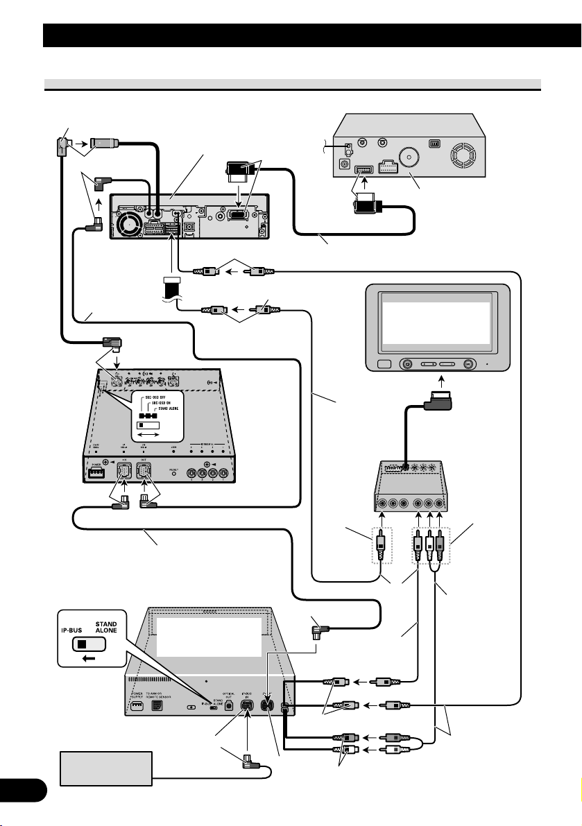
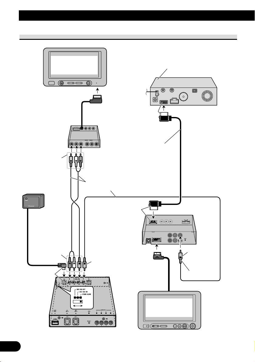
AV-BUS cable
3m
50 cm
Blue
AV-BUS cable
(supplied)
AV-BUS cable
(supplied)
Black
Black
Use AV-BUS cable (50 cm ) if necessary.
Blue
This unit
To front output
(FRONT VIDEO OUT)
To video
1 input
3m
Yellow
Black
IP-BUS cable
(supplied)
IP-BUS input
Pioneer head unit
(sold separately)
Front display
(e.g. AVD-W6210)
(sold separately)
RCA cable
(sold separately)
3m
Remote sensor
(supplied)
Black
When using this unit as “SRC : OSD ON” mode
5
Connecting the Units
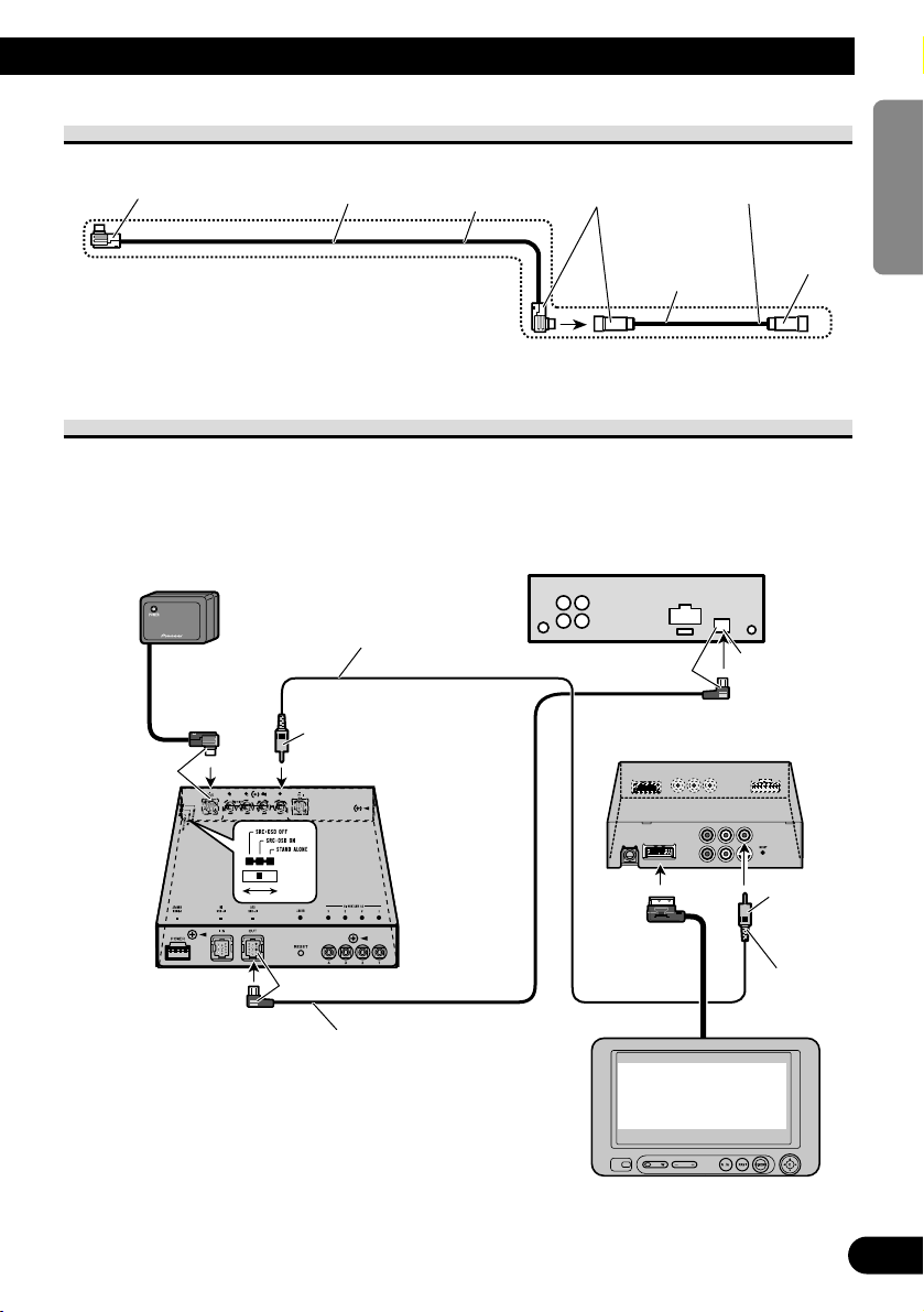
When using this unit as “STAND ALONE” mode
This unit
26-pin cable
(supplied with Pioneer
navigation unit)
To video
1 input
To rear out
(REAR OUT)
To front out
(FRONT VIDEO OUT)
To video
1 input
Black
Yellow
3 m
Black
Pioneer navigation unit
(e.g. AVIC-800DVD)
(sold separately)
RCA cable
(sold separately)
Rear display
(e.g. AVD-W6200)
(sold separately)
Yellow
Front display
(e.g. AVD-W6210)
(sold separately)
Remote sensor
(supplied)
6
ENGLISH ESPAÑOL DEUTSCH FRANÇAIS
ITALIANO NEDERLANDS
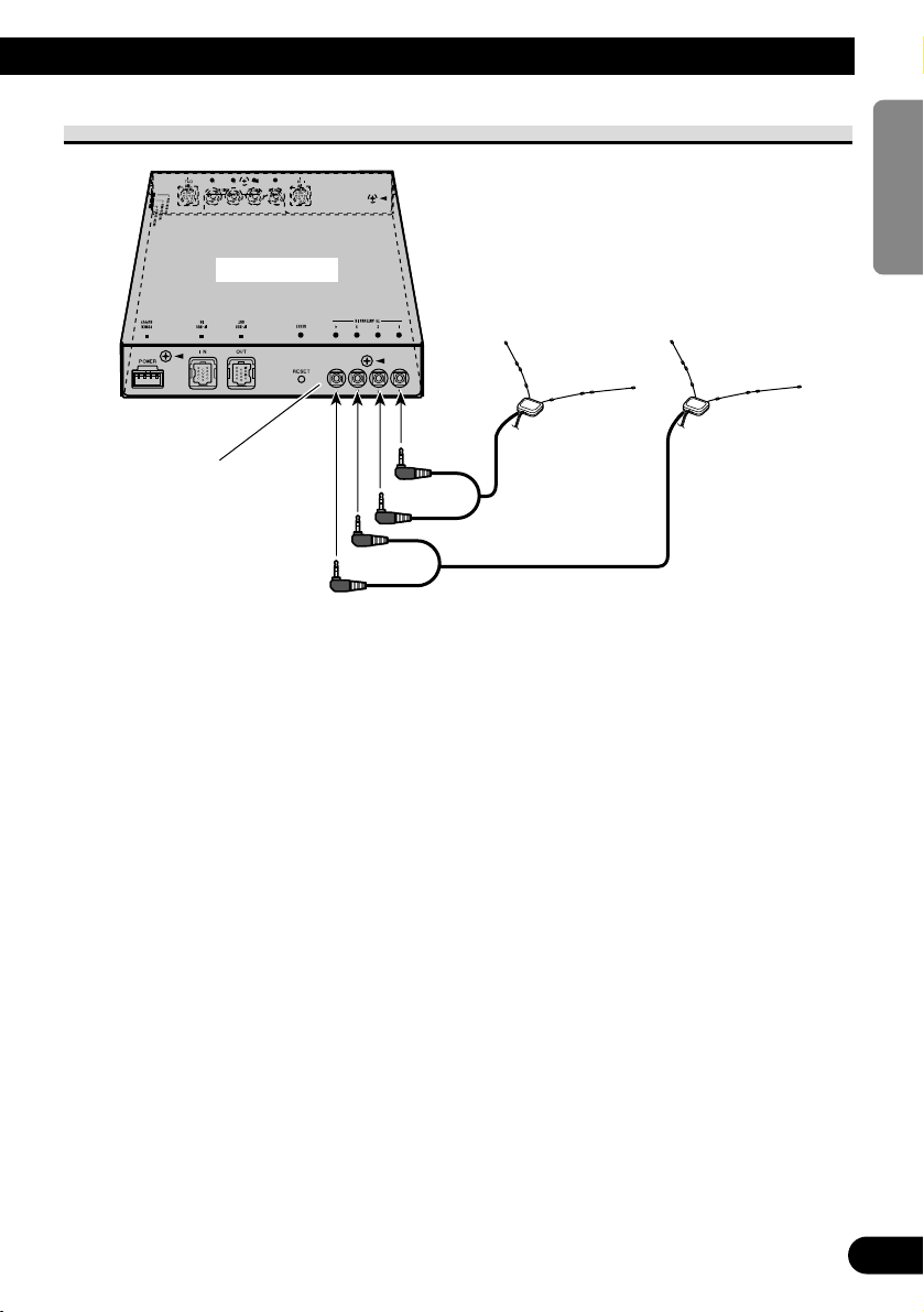
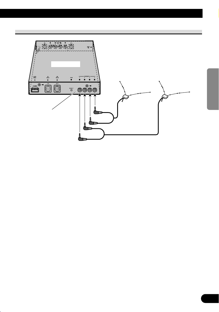
Fig. 3
TV antenna connection
TV antenna inputs
Connect from 1 in order.
TV antenna (sold separately)
This Unit
7
A Title (English)
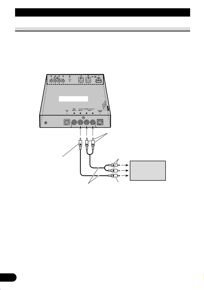
Rear display connection
Note:
• Output to this product’s Rear Display is ON when the Head Unit’s source is TV.
If the Head Unit’s source is anything other than TV or Head Unit is OFF, pressing POWER button on the
supplied remote control enables you to operate TV independently for the Rear Display.
• Output from this product’s rear audio output is monaural.
Connecting the Units
RCA audio output
(White, Red)
RCA cables
(sold separately)
To video input
To audio inputs
Display with RCA
input jacks
This Unit
RCA video output
(Yellow)
8
ENGLISH ESPAÑOL DEUTSCH FRANÇAIS
ITALIANO NEDERLANDS
Installation
Note:
• Before making a final installation of the unit, temporarily connect the wiring to confirm that the
connections are correct and the system works
properly.
• Use only the parts included with the unit to ensure
proper installation. The use of unauthorized parts
can cause malfunctions.
• Consult with your nearest dealer if installation
requires the drilling of holes or other modifications of the vehicle.
• Install the unit where it does not get in the driver’s
way and cannot injure the passenger if there is a
sudden stop, like an emergency stop.
• When mounting this unit, make sure none of the
leads are trapped between this unit and the surrounding metalwork or fittings.
• Do not mount this unit near the heater outlet,
where it would be affected by heat, or near the
doors, where rainwater might splash onto it.
(Never install in locations such as the above
because of the danger of malfunction due to high
temperatures.)
• Before drilling any mounting holes always check
behind where you want to drill the holes. Do not
drill into the gas line, brake line, electrical wiring
or other important parts.
• If this unit is installed in the passenger compartment, anchor it securely so it does not break free
while the car is moving, and cause injury or an
accident.
• If this unit is installed under a front seat, make
sure it does not obstruct seat movement. Route all
leads and cords carefully around the sliding mechanism so they do not get caught or pinched in the
mechanism and cause a short circuit.
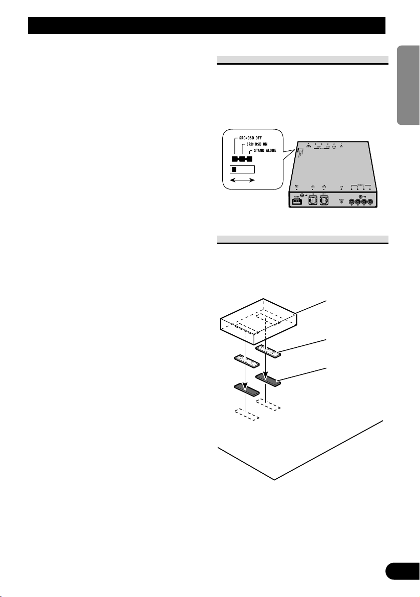
Switching the operation mode
Before installing, use a thin standard
tip screwdriver to switch the operation
mode switch on this unit to the appropriate position for the component you
are using it with.
Installing the Unit
Adhere the hard Velcro tape (provided)
to the bottom of the hide-away unit and
adhere the soft Velcro tape (provided)
to the installation location.
Note:
• Direct installation on the carpet is possible if the
hard Velcro tape will adhere to the carpet. Do not
use the soft Velcro tape in this case.
• Thoroughly wipe off the surface before affixing
the velcro tape.
Car mat or chassis
This unit
Velcro tape
(hard)
Velcro tape
(soft)

1
Conexión de las unidades
Conexión del cable de alimentación .................. 2
En el uso de esta unidad en el modo
“SRC: OSD OFF” ...................................... 3
Cable AV-BUS .................................................. 4
En el uso de esta unidad en el modo
“SRC: OSD ON” ........................................ 4
En el uso de esta unidad como
“STAND ALONE” .................................... 5
Conexión a la antena de TV .............................. 6
Conexión de presentación visual trasera .......... 7
Instalación .................................................. 8
Conmutación del modo de operación
...................... 8
Instalación de la unidad .................................... 8
Conexión de las unidades
Contenido
Nota:
• Esta unidad es para vehículos con una batería de
12 voltios y masa negativa. Antes de montarlo en
un autobús, camión o vehículo de recreación,
compruebe el voltaje de la batería.
• Para evitar cortocircuitos en el sistema eléctrico,
cerciórese de desconectar el cable de batería (–)
antes de comenzar la instalación.
• Para los detalles sobre la conexión a otras
unidades, refiérase al manual del propietario y
luego haga las conexiones correctamente.
• Asegure el cableado con grapas de cable o cinta
aisladora. Para proteger el cableado, envuelva con
cinta aisladora alrededor del cableado en las
partes en donde se apoya contra las partes
metálicas.
• Pase y asegure todo el cableado de modo que no
toque ninguna de la partes móviles, tales como
engranaje de cambio, freno de mano y carriles del
asiento. No pase el cableado por lugares que se
calientan, tales como cerca una salida del
calefactor. Si la aislación del cableado se derrite o
se rompe, existe el peligro de que el cableado se
ponga en cortocircuito con la carrocería del
vehículo.
• No pase el conductor amarillo a través de un
orificio en el compartimiento del motor para
conectar a la batería. Esto dañará el material
aislante del conductor y causará un cortocircuito
peligroso.
• No ponga en cortocircuito ninguno de los
conductores. Si lo hace, el circuito de protección
fallará en el momento que deba funcionar.
• No alimente otro equipo cortando la aislación del
conductor de suministro de alimentación de la
unidad y enrrollando en el conductor. La
capacidad actual del conductor será excedida,
ocasionando sobrecalentamiento.
• Cuando reemplace algún fusible, asegúrese de
utilizar solamente un fusible del régimen
especificado en el portafusible.
• Para evitar una conexión incorrecta, el lado de
entrada del conector IP-BUS es azul, y el lado de
salida es negro. Conecte los conectores de los
mismos colores correctamente.
• Para minimizar el ruido ubique el cable de la
antena de TV, el cable de la antena de radio y
cable RCA tan alejados como sea posible uno de
otro.
• Los cables para esta unidad y aquéllas para las
unidades pueden ser de colores diferentes aun
si tienen la misma función. En la conexión de
este producto a otro, refiérase a los manuales
suministrados de ambos productos y conecte
los cordones que ofrecen la misma función.
2
ENGLISH
ESPAÑOL DEUTSCH FRANÇAIS
ITALIANO NEDERLANDS
Esta unidad
Portafusible
Amarillo
Al terminal con suministro constante de
electricidad, independientemente de la
posición del interruptor de encendido.
Negro (masa)
A la carrocería del veículo (parte metálica).
Rojo
(Conecte este cable sólo cuando se utilice
la unidad en modo STAND ALONE.)
Al terminal de energía eléctrica controlado
por el interruptor de encendido del vehículo
(12 V de CC.) ON/OFF.
.
Interruptor del freno de mano
Lado de alimentación
Verde claro
Se utiliza para detectar el estado ON/OFF
del freno de mano. Este cable debe
conectarse al lado de alimentación del
interruptor del freno de mano.
Resistencia
de fusible
Lado de masa
1. Apriete el cable. 2. Apriete
firmemente con
alicates de punta
de aguja.
Nota:
• La posición del freno de estacionamiento depende
del modelo del vehículo. Para conocer detalles, consulte
el manual del propietario del vehículo o a su concesionario.
Método de connexión
Conexión del cable de alimentación

Azul
Esta unidad
A la salida de video
Cable AV-BUS
(suministrado)
Receptor AV
(ej. AVH-P5700DVD)
(vendido separadamente)
Cable de 26 clavijas
(suministrado la unidad de navegación de Pioneer)
A la entrada
de video 1
A la entrada
de video 2
Azul
Negro
Amarillo
Blanco/Rojo
3 m
3 m
Amarillo
Amarillo
Amarillo
Negro
Negro
Negro
Negro
Unidad de navegación de
Pioneer
(ej. AVIC-800DVD)
(vendido separadamente)
Cable IP-BUS
(suministrado)
Cable RCA
(vendido
separadamente)
Visualizador trasero
(ej. AVD-W6200)
(vendido separadamente)
Cable IP-BUS
(vendido separadamente)
Blanco/Rojo
Cable RCA
(vendido
separadamente)
Reproductor de DVD
(ej. XDV-P9II)
(vendido separadamente)
Reproductor Multi-CD
(vendido separadamente)
Amarillo
Cable RCA
(suministrado con el
reproductor de DVD)
Azul
3
Conexión de las unidades
En el uso de esta unidad en el modo “SRC: OSD OFF”
4
ENGLISH
ESPAÑOL DEUTSCH FRANÇAIS
ITALIANO NEDERLANDS
Cable AV-BUS
3m
50 cm
Azul
Cable AV-BUS
(suministrado)
Cable AV-BUS
(suministrado)
Negro
Negro
Use el cable AV-BUS (50 cm) si fuera necesario.
Azul
Esta unidad
A la salida frontal
(FRONT VIDEO OUT)
A la entrada de
video 1
3 m
Amarillo
Negro
Cable IP-BUS
(suministrado)
Entrada IP-BUS
Unidad de cabeza de Pioneer
(vendido separadamente)
Visualizador frontal
(ej. AVD-W6210)
(vendido separadamente)
Cable RCA
(vendido separadamente)
3 m
Sensor remoto
(suministrado)
Negro
En el uso de esta unidad en el modo “SRC: OSD ON”
5
Conexión de las unidades
En el uso de esta unidad como “STAND ALONE”
Esta unidad
Cable de 26 clavijas
(suministrado con la unidad
de navegación de Pioneer)
A la entrada
de video 1
A la salida trasera
(REAR OUT)
A la salida frontal
(FRONT VIDEO OUT)
A la entrada
de video 1
Negro
Amarillo
3 m
Negro
Unidad de navegación de Pioneer
(ej. AVIC-800DVD)
(vendido separadamente)
Cable RCA
(vendido separadamente)
Visualizador trasero
(ej. AVD-W6200)
(vendido separadamente)
Amarillo
Visualizador frontal
(ej. AVD-W6210)
(vendido separadamente)
Sensor remoto
(suministrado)
6
ENGLISH
ESPAÑOL DEUTSCH FRANÇAIS
ITALIANO NEDERLANDS
Fig. 3
Conexión a la antena de TV
Entradas de antena de TV
Conecte desde 1 en orden.
Antena de TV (vendido separadamente)
Esta unidad
 Loading...