


PIONEER GE-2037 Service Manual
PIONEER CORPORATION 4-1, Meguro 1-Chome, Meguro-ku, Tokyo 153-8654, Japan
PIONEER ELECTRONICS (USA) INC. P.O.Box 1760, Long Beach, CA 90801-1760 U.S.A.
PIONEER EUROPE NV Haven 1087 Keetberglaan 1, 9120 Melsele, Belgium
PIONEER ELECTRONICS ASIACENTRE PTE.LTD. 253 Alexandra Road, #04-01, Singapore 159936
C PIONEER CORPORATION 2003
K-ZZA. JUNE 2003 Printed in Japan
ORDER NO.
CRT3104
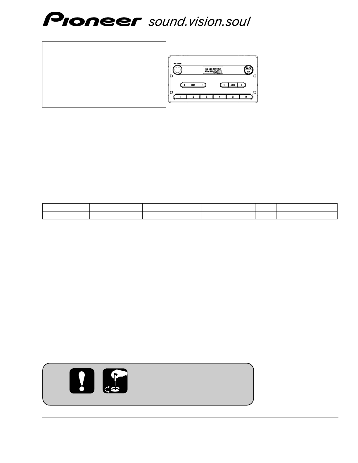
RECEIVER ASSY RADIO
GE-2037ZFXU/UC
FORD
GE-2037ZF/XU/UC
VEHICLE DESTINATION PRODUCED AFTER FORD PART No. ID No. PIONEER MODEL No.
Ranger U.S.A., CANADA August 2003 4L5T-18K810- GE-2037ZF/XU/UC
For details, refer to "Important symbols for good services".
2
1
234
12
34
F
E
D
C
B
A
GE-2037ZF/XU/UC
SAFETY INFORMATION
[ Important symbols for good services ]
In this manual, the symbols shown-below indicate that adjustments, settings or cleaning should be made securely.
When you find the procedures bearing any of the symbols, be sure to fulfill them:
1. Product safety
You should conform to the regulations governing the product (safety, radio and noise, and other regulations), and
should keep the safety during servicing by following the safety instructions described in this manual.
2. Adjustments
To keep the original performances of the product, optimum adjustments or specification confirmation is indispensable.
In accordance with the procedures or instructions described in this manual, adjustments should be performed.
3. Cleaning
For optical pickups, tape-deck heads, lenses and mirrors used in projection monitors, and other parts requiring cleaning,
proper cleaning should be performed to restore their performances.
4. Shipping mode and shipping screws
To protect the product from damages or failures that may be caused during transit, the shipping mode should be set or
the shipping screws should be installed before shipping out in accordance with this manual, if necessary.
5. Lubricants, glues, and replacement parts
Appropriately applying grease or glue can maintain the product performances. But improper lubrication or applying
glue may lead to failures or troubles in the product. By following the instructions in this manual, be sure to apply the
prescribed grease or glue to proper portions by the appropriate amount.For replacement parts or tools, the prescribed
ones should be used.
This service manual is intended for qualified service technicians; it is not meant for the casual do-it-yourselfer.
Qualified technicians have the necessary test equipment and tools, and have been trained to properly and safely repair
complex products such as those covered by this manual.
Improperly performed repairs can adversely affect the safety and reliability of the product and may void the warranty.
If you are not qualified to perform the repair of this product properly and safely, you should not risk trying to do so
and refer the repair to a qualified service technician.

3
5
6
7
8
F
E
D
C
B
A
5
6
7
8
GE-2037ZF/XU/UC
CONTENTS
SAFETY INFORMATION......................................................................................................................................................2
1. SPECIFICATIONS .................................................................................................................................................................4
2. EXPLODED VIEWS AND PARTS LIST ................................................................................................................................5
2.1 PACKING..........................................................................................................................................................................5
2.2 EXTERIOR........................................................................................................................................................................6
3. BLOCK DIAGRAM AND SCHEMATIC DIAGRAM...............................................................................................................8
3.1 BLOCK DIAGRAM ...........................................................................................................................................................8
3.2 OVERALL CONNECTION DIAGRAM(GUIDE PAGE) ...................................................................................................10
3.3 KEYBOARD UNIT ..........................................................................................................................................................16
4. PCB CONNECTION DIAGRAM..........................................................................................................................................18
4.1 TUNER AMP UNIT ........................................................................................................................................................18
4.2 KEYBOARD UNIT ..........................................................................................................................................................22
5. ELECTRICAL PARTS LIST..................................................................................................................................................24
6. ADJUSTMENT ...................................................................................................................................................................27
6.1 FREQUENCY CHECK FOR CLOCK ...............................................................................................................................27
7. GENERAL INFORMATION.................................................................................................................................................28
7.1 DIAGNOSIS ...................................................................................................................................................................28
7.1.1 DISASSEMBLY .......................................................................................................................................................28
7.1.2 CONNECTOR FUNCTION DESCRIPTION .............................................................................................................30
7.2 PARTS ............................................................................................................................................................................31
7.2.1 IC .............................................................................................................................................................................31
7.2.2 DISPLAY..................................................................................................................................................................34
7.3 OPERATIONAL FLOW CHART......................................................................................................................................35
8. OPERATIONS .....................................................................................................................................................................36

4
1
234
12
34
F
E
D
C
B
A
GE-2037ZF/XU/UC
1. SPECIFICATIONS
General
Power source ..............................................................................14.4V(10.5V-16.0V allowable) DC
Grounding system ......................................................................Negative type
Backup current ............................................................................3mA or less
Dimensions (Chassis) ...............................................................180(W) x90(H) x166(D)mm
(Grille) ...................................................................188(W) x100(H) x23(D)mm
Weight .........................................................................................1.25kg
FM tuner
Frequency....................................................................................87.75, 87.9-107.9 MHz
S/N ...............................................................................................58dB or more
Distortion.....................................................................................1.5% or less
IF interference .............................................................................95dB or more
Image interference......................................................................45dB or more
Stereo Separation.......................................................................25dB or more(400Hz)
AM tuner
Frequency....................................................................................530-1710 kHz
S/N 20dB useable sensibility .....................................................33dBµ 6dB
S/N ...............................................................................................50dB +10dB, -6dB
Distortion.....................................................................................2.0% or less
IF interference .............................................................................75dB or more
Image interference......................................................................60dB or more
5
6
7
8
F
E
D
C
B
A
5
6
7
8
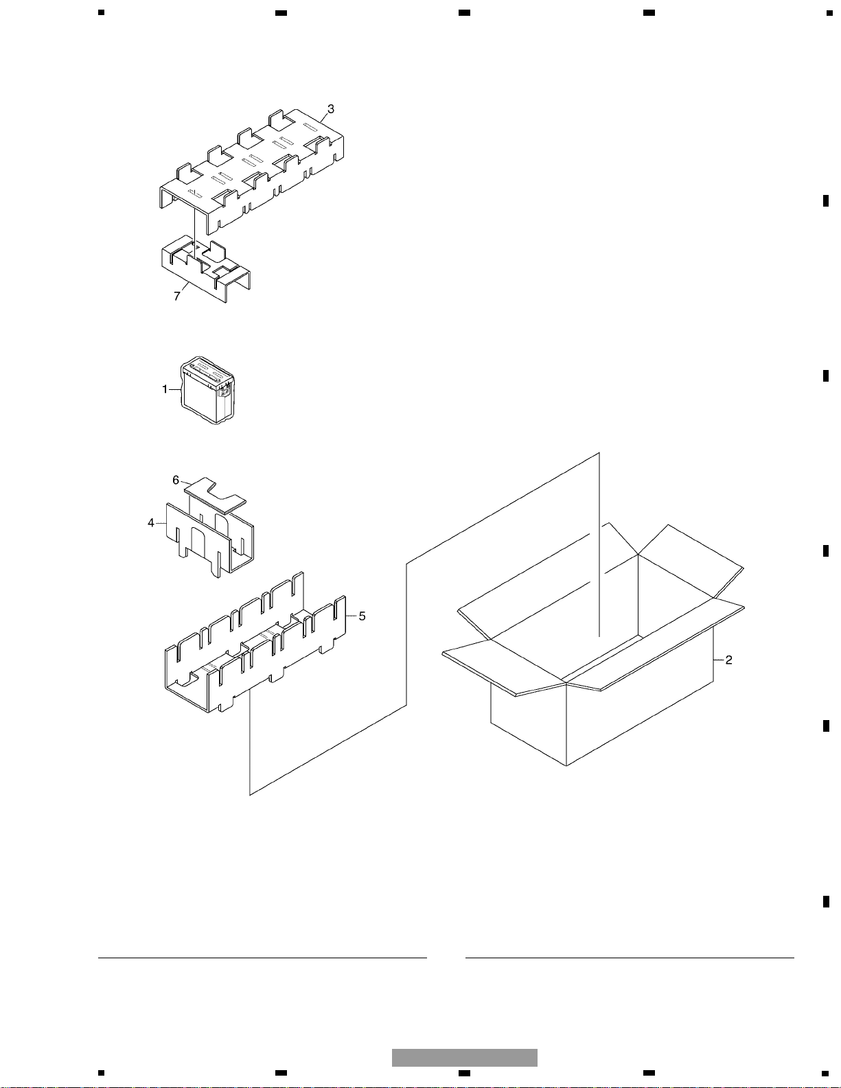
2. EXPLODED VIEWS AND PARTS LIST
2.1 PACKING
* 1 Polyethylene Bag CEG1317
2 Contain Box CHL4768
3 Protector CHP2619
4 Protector CHP2620
5 Protector CHP2621
6 Protector CHP2622
7 Protector CHP2717
Mark No. Description Part No. Mark No. Description Part No.
NOTE:
- Parts marked by “*” are generally unavailable because they are not in our Master Spare Parts List.
- Screws adjacent to ∇ mark on the product are used for disassembly.
- For the applying amount of lubricants or glue, follow the instructions in this manual.
( In the case of no amount instructions, apply as you think it appropriate.)
- PACKING SECTION PARTS LIST
GE-2037ZF/XU/UC
5
6
1
234
12
34
F
E
D
C
B
A
GE-2037ZF/XU/UC
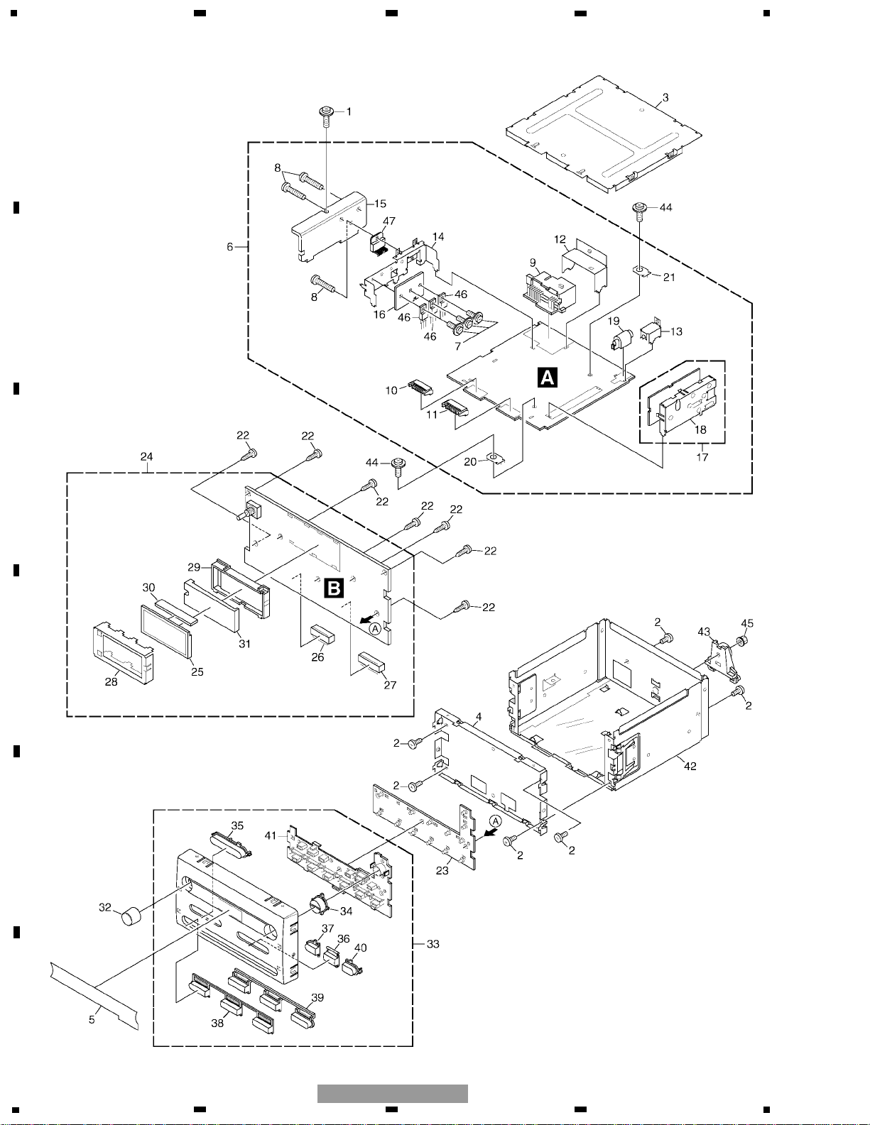
2.2 EXTERIOR

1 Screw ASZ26P100FTC
2 Screw BSZ26P060FTC
3 Case CNB2733
4 Holder CNC9806
5 Sheet CNM8581
6 Tuner Amp Unit CWM8232
7 Screw ASZ26P100FTC
8 Screw BSZ26P100FTC
9 Plug(CN901) CKM1372
10 Plug(CN802) CKS3537
11 Plug(CN801) CKS3538
12 Holder CNC9801
13 Holder CNC9802
14 Holder CNC9803
15 Heat Sink CNC9804
16 Heat Sink CNC9805
17 FM/AM Tuner Unit CWE1561
18 Holder CNC8855
19 Antenna Jack(CN401) HKX1054
20 Terminal(CN402) VNF1084
21 Terminal(CN403) VNF1084
22 Screw BPZ26P100FTC
23 Rubber CNV7759
24 Keyboard Unit CWM8233
25 LCD(LCD801) CAW1683
26 Socket(CN803) CKS3550
27 Socket(CN804) CKS3551
28 Holder CNC9807
* 29 Housing CNV7056
30 Connector CNV7604
31 Lighting Conductor CNV7935
32 Knob Unit(VOL, PUSH) CXB8558
33 Grille Unit CXC2287
34 Button(AM, FM, CLK) CAC7499
35 Button({ SEEK }) CAC7500
36 Button(AUDIO) CAC7501
37 Button({) CAC7502
38 Button(1, 3, 5) CAC7503
39 Button(2, 4, 6) CAC7504
40 Button(}) CAC7686
41 Housing CNV7058
42 Chassis Unit CXB8522
43 Rail Guide HNV6756
44 Screw ISS26P055FTC
45 Nut NF50FTC
46
Transistor(Q923, 951, 961) 2SB942
47 IC(IC301) PAL001A
7
5
6
7
8
F
E
D
C
B
A
5
6
7
8
GE-2037ZF/XU/UC
Mark No. Description Part No. Mark No. Description Part No.
- EXTERIOR SECTION PARTS LIST
8
41
MUTE
XOUT
XIN
SYSTEM CONTROL
IC 601(2/2)
PD5757A
CN401
VDD
VCC
ANTENNA
JACK
1
2
10
X601
12
EVS
65
lcdpw
ILMOUT
3
BLPWR
2
Lch
Q401
LOCL
PDIO
A
TUNER AMP UNIT
FM/AM TUNER UNIT
Q
B.UP
ILMPW
BLPWR
Q961
Q962
B.UP
Q964
53
LOTIN0
52
LOTIN1
42
pwrkey
17
LOTINT
A
SCLKO
SCLKIN
8
X602
7
Q963
clkky
71
Q952
lcdpw
IC 3
EEPROM
28
27
FM/AM 1ST IF 10.7MHz
T51 Q51 CF51
CF52 CF53
IC1
MIXER, IF AMP, DET.
6
21
18
LDET
COMP
222510 14 12 15 16 8 13 2 3 4
CF202
VDD
VCC
DI/DO
CE2CKCE1
SDBWSLFMSD
NL1
NL2
IC 2 FM MPX
AMANT
FMANT
ATT
ATT
AMRF
FMRF
IMG ADJ
RF ADJ
X901
10.25MHz
ANT ADJ
LOCL
23
LOCH
AMDET
MPXREF 41kHz
AM 2ND IF
450kHz
19
CREQ
11
DGND
1
STIND
L ch
5
R ch
924
AMDET
FMLOCL
20
177
AMPNS
WC
26
RFGND
AMIN
1
234
12
34
F
E
D
C
B
A
GE-2037ZF/XU/UC
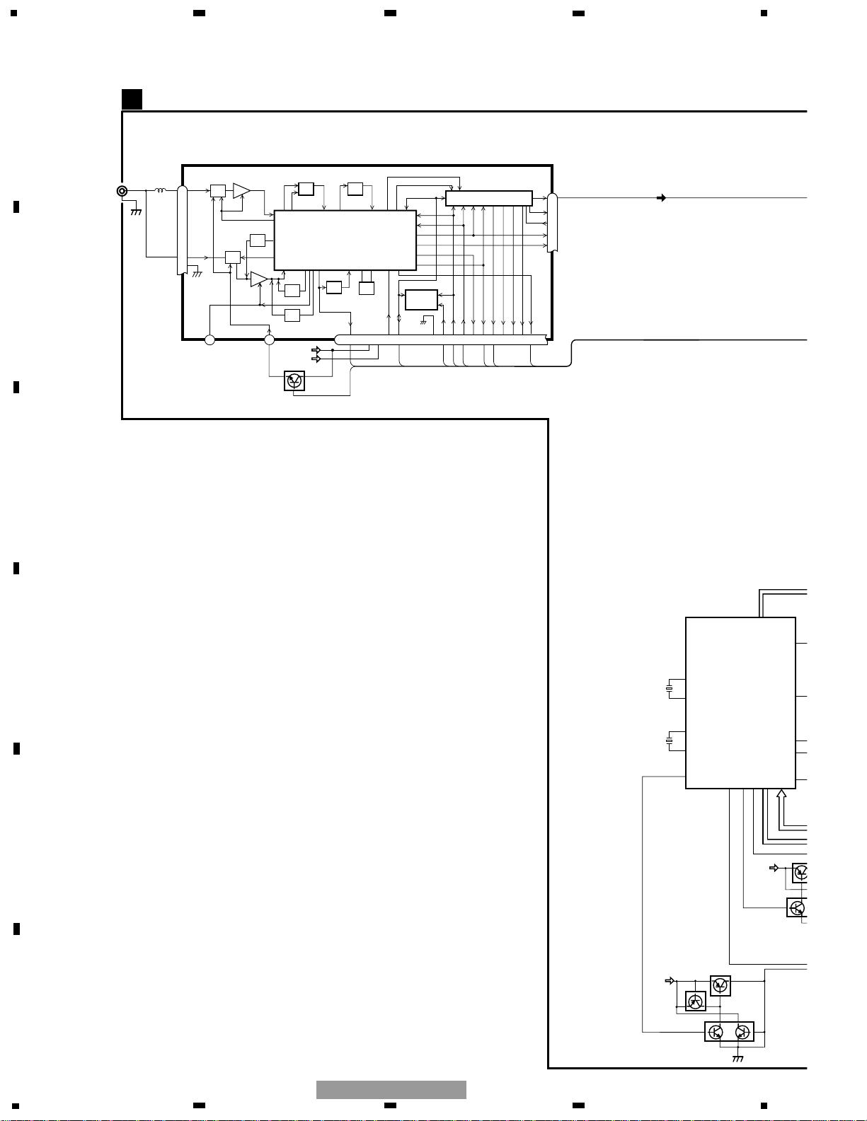
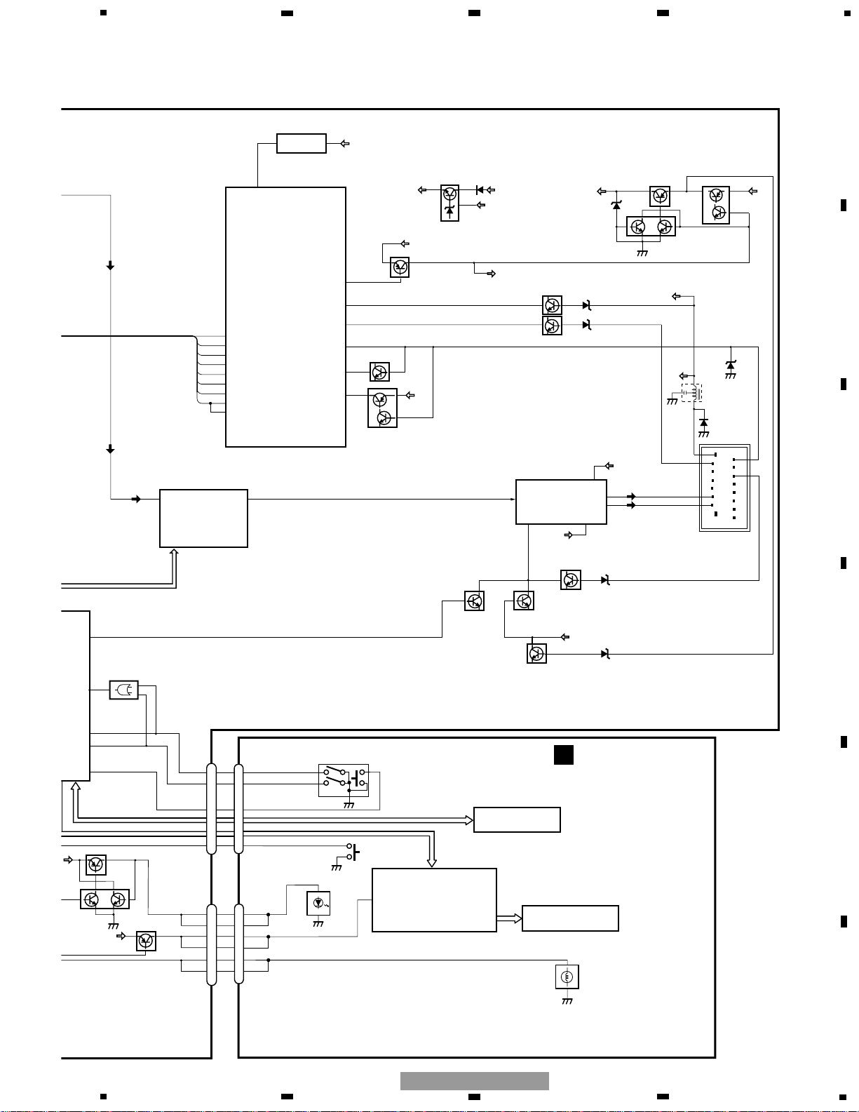
3. BLOCK DIAGRAM AND SCHEMATIC DIAGRAM
3.1 BLOCK DIAGRAM
9
18
916
SYSPWR
VDD
B.UP
VDD REGULATOR
Q911
9
1
bsens
asens
VDD
LOCL
18
15
SD
SL
PLLCE
pck
pllce@
PDO
10
F Lch
41
MUTE
ILL+B
ACC
34
35
76
LIN1-L
2
31
30
33
28
SYSTEM CONTROL
RESET
IC 601(1/2)
PD5757A
IC 101
PML010A
S-80843CNUA-B84
reset
Q651
VDD
8
2
CN801
2
Q656
EVST,EDT,ECLK
TUN L
FL+
FL-
CN901
ILMI
74
A SENSE
PDI
29
PDIO
syspw
40
Q923
Q924
B.UP
SYSPW
VCC
Q951
Q953
BL+B
Q672
Q671
IC 676
VDD
7
B.UP
B SENSE
ILMIN
15
14
FL+
FL-
IN2
10
4,5
12
POWER AMP
E-VOL
IC 301
PAL001A
STBY
MUTE
B.UP
3,13
SYSPW
Q921
Q922
VCC REGULATOR
Q676
VDD
RUN/ACC
Q661
ilmint
16
PWMIN
5
Q931
SWD5V
SYSPW
Q302Q301
MUTE
11
10
ROTIN1
ROTIN0
53
LOTIN0
52
LOTIN1
42
pwrkey
TC7S86F
IC 871
2
1
4
17
LOTINT
kdt)-kdt#,kst)-kst#
LCDCL,LCDDT,LCDST
B.UP
BACKUP
ILL+
RUN/ACC
st
36
START
Q681
START
START
Q901
B.UP
HARD MUTE
PWM
4
CN802
16
3
9
10
power
clkky
RUN/ACC
Q952
ILM
SWVDD
IC 801
LC75822W
LCD DRIVER
KEY MATRIX
7
8
VDD
56
CN804
KEYBOARD UNIT
LCD
B
2
BL+B
ILLUMINATION
VR851
2
1
10
11
ROTIN1
ROTIN0
ROTIN1
ROTIN0
LCD BACKLIGHT
4
5
VOLUME/POWER
kd)-kd#,ks)-ks#
CL,DT,CE
CN803
16
ROWER
3
CLOCK
CLKKY
4
9
10
5
6
7
8
F
E
D
C
B
A
5
6
7
8
GE-2037ZF/XU/UC
10
A-a A-b
A-a
A-b
A-b
A-a
Large size
SCH diagram
Guide page
Detailed page
Note: When ordering service parts, be sure to refer to " EXPLODED VIEWS AND PARTS LIST" or
"ELECTRICAL PARTS LIST".
A-a
A
FM/AM TUNER UNIT
1
234
12
34
F
E
D
C
B
A
GE-2037ZF/XU/UC
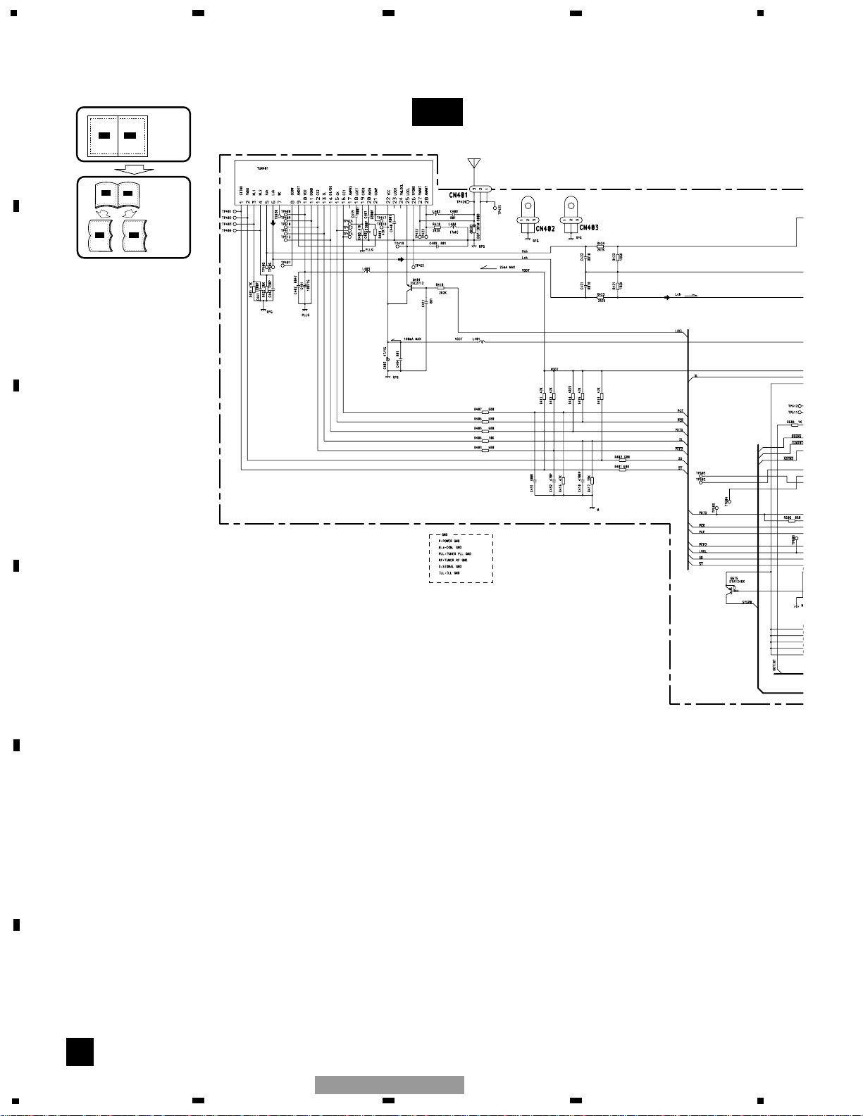
3.2 OVERALL CONNECTION DIAGRAM(GUIDE PAGE)
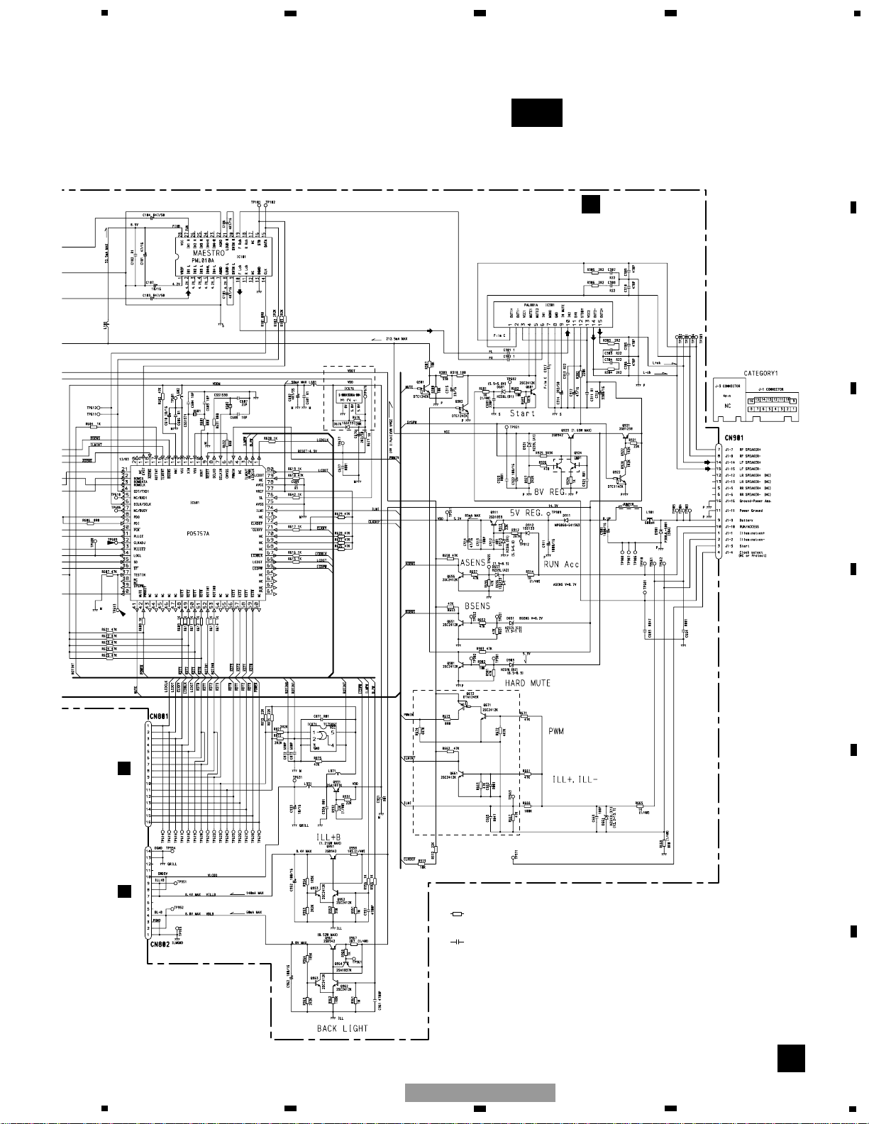
11
A-b
A
16.000MHz 32.768Hz
SYSTEM CONTROLLER
RESET
E-VOL
POWER AMP
Decimal points for resistor
and capacitor fixed values
are expressed as :
2.2 2R2
0.022 R022
←
←
Symbol indicates a resistor.
No differentiation is made between chip resistors and
discrete resistors.
NOTE :
Symbol indicates a capacitor.
No differentiation is made between chip capacitors and
discrete capacitors.
B
A
TUNER AMP UNIT
CN804
B
CN803
FM : 23.4dBs(100%, 1kHz)
AM : 14.1dBs(30%, 1kHz)
FM : -8.6dBs(100%, 1kHz)
AM : -17.9dBs(30%, 1kHz)
FM : -20.7dBs(100%, 1kHz)
AM : -30dBs(30%, 1kHz)
5
6
7
8
F
E
D
C
B
A
5
6
7
8
GE-2037ZF/XU/UC