

PIONEER FH-M2017 Service Manual
PIONEER CORPORATION 4-1, Meguro 1-Chome, Meguro-ku, Tokyo 153-8654, Japan
PIONEER ELECTRONICS (USA) INC. P.O.Box 1760, Long Beach, CA 90801-1760 U.S.A.
PIONEER EUROPE NV Haven 1087 Keetberglaan 1, 9120 Melsele, Belgium
PIONEER ELECTRONICS ASIACENTRE PTE.LTD. 253 Alexandra Road, #04-01, Singapore 159936
C PIONEER CORPORATION 2001
K-ZZU. SEPT. 2001 Printed in Japan
ORDER NO.
CRT2723
MULTI CD CONTROL FM/AM CASSETTE DECK
FH-M2017ZT X1N/ES
TOYOTA
- This service manual should be used together with the following manual(s):
Model No. Order No. Mech. Module Remarks
CX-1011 CRT2406 3L
Cassette Mech. Module:Mech.Description, Disassembly
CX-977 CRT2624 S9
CD Mech. Module:Circuit Description, Mech.Description, Disassembly
CONTENTS
1. SAFETY INFORMATION ............................................3
2. EXPLODED VIEWS AND PARTS LIST.......................4
3. BLOCK DIAGRAM AND SCHEMATIC DIAGRAM ...10
4. PCB CONNECTION DIAGRAM ................................26
5. ELECTRICAL PARTS LIST ........................................36
6. ADJUSTMENT..........................................................41
7. GENERAL INFORMATION .......................................55
7.1 DIAGNOSIS ........................................................55
7.1.1 DISASSEMBLY .........................................55
7.1.2
CONNECTOR FUNCTION DESCRIPTION........59
7.2 PARTS .................................................................60
7.2.1 IC................................................................60
7.2.2 DISPLAY....................................................68
7.3 OPERATIONAL FLOW CHART...........................69
8. OPERATIONS AND SPECIFICATIONS.....................70
- Dolby noise reduction manufactured under license from Dolby Laboratories Licensing Corporation.
"Dolby" and the double-D symbol are trademarks of Dolby Laboratories Licensing Corporation.
VEHICLE DESTINATION PRODUCED AFTER TOYOTA PART No. ID No. PIONEER MODEL No.
HILUX THAILAND October 2001 86120-YZB21 T2602 FH-M2017ZT/X1N/ES

2
FH-M2017ZT
- CD Player Service Precautions
1. For pickup unit(CXX1482) handling, please refer
to"Disassembly"(see page 55).
During replacement, handling precautions shall be
taken to prevent an electrostatic discharge(protection
by a jumper-solder).
2. During disassembly, be sure to turn the power off
since an internal IC might be destroyed when a con-
nector is plugged or unplugged.
3. Please checking the grating after changing the ser-
vice pickup unit(see page 44).

3
FH-M2017ZT
This service manual is intended for qualified service technicians; it is not meant for the casual do-it-yourselfer.
Qualified technicians have the necessary test equipment and tools, and have been trained to properly and safely repair
complex products such as those covered by this manual.
Improperly performed repairs can adversely affect the safety and reliability of the product and may void the warranty.
If you are not qualified to perform the repair of this product properly and safely, you should not risk trying to do so and
refer the repair to a qualified service technician.
1. SAFETY INFORMATION
4
FH-M2017ZT
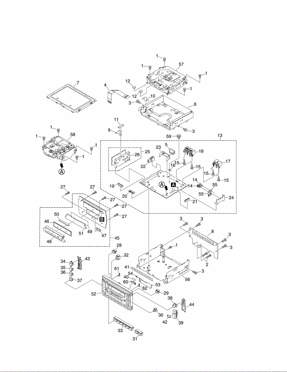
2. EXPLODED VIEWS AND PARTS LIST
2.1 EXTERIOR

5
FH-M2017ZT
1 Screw BSZ26P060FMC
2 Screw BSZ26P120FMC
3 Screw BSZ30P080FMC
4 Connector CDE6545
5 IC(IC302) TDA7384
6 Chassis CNA2380
7 Case CNB2653
8 Heat Sink CNC9589
9 Earth Plate CNC9600
10 Insulator CNM7489
11 Cushion CNM7492
12 Cushion CNM7541
13 Main Unit CWM7902
14 Screw BSZ30P060FMC
15 Screw(M3x4) CBA1393
16 Terminal(CN403) CKF1059
17 Plug(CN402) CKM1221
18 Connector(CN401) CKM1222
19 Connector(CN651) CKS2770
20 Plug(CN681) CKS3537
21 Connector(CN621) CKS3568
22 Antenna Jack(ANT1) CKX1060
23 Holder CNC9287
24 Holder CNC9288
25 FM/AM Tuner Unit CWE1557
26 Holder CNC8855
27 Screw BPZ26P100FMC
28 Button(PWR) CAC6954
29 Button(CD EJECT) CAC6955
30 Button(TAPE EJECT) CAC6957
31 Button(SEEK) CAC7054
32 Button(EQ) CAC7148
33 Button(1-6) CAC7149
34 Button(DISC) CAC7470
35 Button(AM/FM) CAC7471
36 Button( ) CAC7472
37 Button(TAPE) CAC7473
38 Button(SCAN) CAC7474
39 Button(VOL) CAC7475
40 Spacer CNM6151
41 Cover CNM6267
42 Holder CNS6946
43 Holder CNV6686
44 Holder CNV6687
45 Keyboard Unit CWM7903
46 LCD CAW1684
47 Socket(CN901) CKS3550
48 Holder CNC7806
49 Spacer CNM6024
50 Connector CNV5386
51 Lighting Conductor CNV5750
52 Grille CNS6705
53 Door CAT2282
54 Spring CBH1371
55 Transistor(Q441,451) 2SB1185
56 Chassis Unit CXB7831
57
CD Mechanism Module(S9T)CXK5520
58
Cassette Mechanism ModuleEXK4247
59 Screw ISS26P055FUC
60 Lighting Conductor CNV5704
61 Lighting Conductor CNV6680
62 Lighting Conductor CNV6682
- EXTERIOR SECTION PARTS LIST
Mark No. Description Part No. Mark No. Description Part No.
NOTE:
- Parts marked by “*”are generally unavailable because they are not in our Master Spare Parts List.
- Screws adjacent to
∇ mark on the product are used for disassembly.
6
FH-M2017ZT
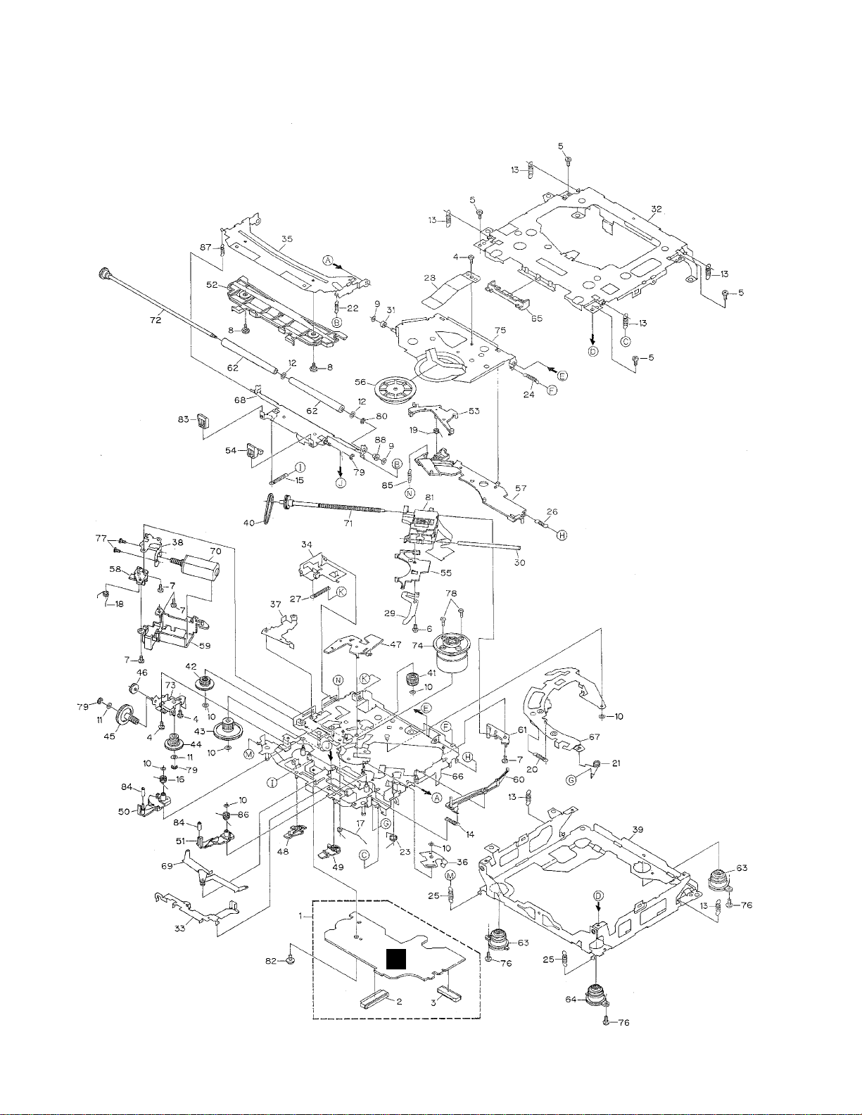
2.2 CD MECHANISM MODULE
C

7
FH-M2017ZT
1 Control Unit CWX2608
2 Connector(CN701) CKS1959
3 Connector(CN101) CKS3486
4 Screw BMZ20P025FMC
5 Screw BSZ20P040FMC
6 Screw(M2x4) CBA1362
7 Screw(M2x3) CBA1527
8 Screw CBA1545
9 Washer CBF1037
10 Washer CBF1038
11 Washer CBF1039
12 Washer CBF1060
13 Spring CBH2378
14 Spring CBH2379
15 Spring CBH2514
16 Spring CBH2533
17 Spring CBH2382
18 Spring CBH2383
19 Spring CBH2384
20 Spring CBH2527
21 Spring CBH2386
22 Spring CBH2537
23 Spring CBH2390
24 Spring CBH2391
25 Spring CBH2523
26 Spring CBH2426
27 Spring CBH2444
28 Spring CBL1494
29 Spring CBL1553
30 Shaft CLA3845
31 Roller CLA3910
32 Frame CNC9654
33 Lever CNC9664
34 Lever CNC8949
35 Arm CNC9661
36 Arm CNC9016
37 Arm CNC9017
38 Bracket CNC9123
39 Frame CNC9656
40 Belt CNT1086
41 Gear CNV6886
42 Gear CNV6316
43 Gear CNV6317
44 Gear CNV6318
45 Gear CNV6319
46 Gear CNV6320
47 Arm CNV6322
48 Arm CNV6323
49 Arm CNV6324
50 Arm CNV6888
51 Arm CNV6889
52 Guide CNV6327
53 Arm CNV6924
54 Guide CNV6921
55 Rack CNV6923
56 Clamper CNV6331
57 Arm CNV6332
58 Guide CNV6333
59 Cover CNV6334
60 Arm CNV6335
61 Guide CNV6336
62 Roller CNV6338
63 Damper CNV6175
64 Damper CNV6662
65 Guide CNV6925
66 Chassis Unit CXB7980
* 67 Arm Unit CXB7983
68 Arm Unit CXB7984
69 Arm Unit CXB7985
70 Motor Unit(M2) CXB5903
71 Screw Unit CXB5904
72 Gear Unit CXB8076
73 Bracket Unit CXB7982
74 Motor Unit(M1) CXB6007
75 Arm Unit CXB7981
76 Screw(M2x5) EBA1028
77 Screw JFZ20P020FMC
78 Screw JGZ17P020FZK
79 Washer YE15FUC
80 Washer YE20FUC
81 Pickup Unit(Service)(P9) CXX1482
82 Screw IMS26P030FMC
83 Guide CNV6922
84 Roller CNV6887
85 Spring CBH2509
86 Spring CBH2512
87 Spring CBH2536
88 Collar CNV6906
- CD MECHANISM MODULE SECTION PARTS LIST
Mark No. Description Part No.
Mark No. Description Part No.
8
FH-M2017ZT
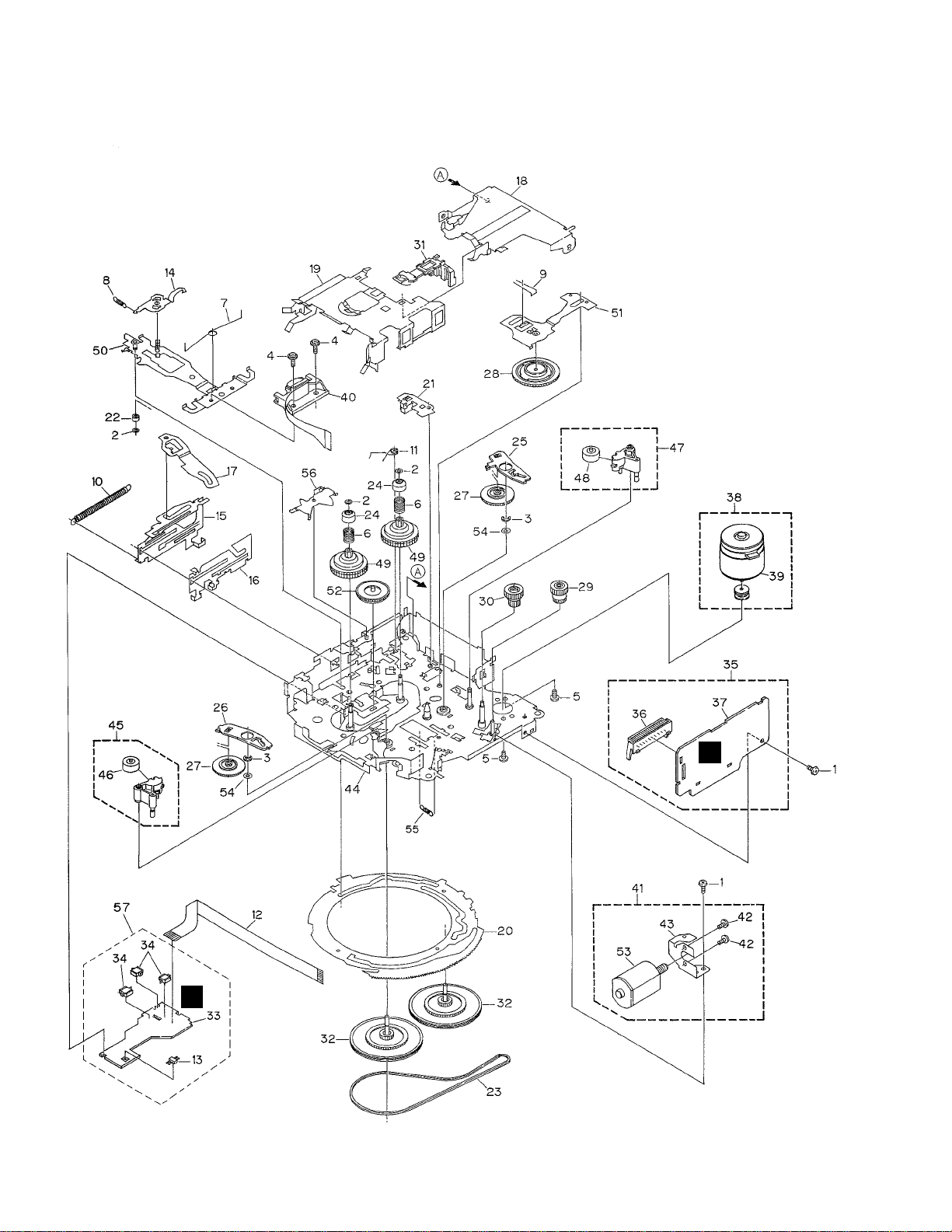
2.3 CASSETTE MECHANISM MODULE
D
E

9
FH-M2017ZT
1 Screw BSZ20P040FMC
2 Washer CBF1037
3 Washer CBG1003
4 Screw EBA1028
5 Screw CBA1037
6 Spring EBH1653
7 Spring EBH1642
8 Spring EBH1641
9 Spring EBH1626
10 Spring EBH1627
11 Spring EBH1648
12 Cord EDD1024
13 Photo-reflector(Q101) EGN1004
14 Arm ENC1526
* 15 Lever ENC1544
16 Lever ENC1543
17 Arm ENC1532
18 Frame ENC1533
19 Holder ENC1534
20 Gear ENC1535
21 Arm ENC1550
22 Roller ENR1040
23 Belt ENT1027
24 Collar ENV1508
25 Arm ENV1539
26 Arm ENV1540
27 Gear ENV1569
28 Gear ENV1547
29 Gear ENV1560
30 Worm Wheel ENV1566
31 Lever ENV1551
32 Flywheel ENV1554
33 Gathering PCB ENX1073
34 Switch(S101,102,103) ESG1007
35 Deck Unit EWM1033
36 Plug(CN251) CKS3540
37 Gathering PCB ENX1067
38 Motor Unit(M1) EXA1491
39 Motor EXM1028
40 Head Assy(HD1) EXA1630
41 Motor Unit(M2) EXA1580
42 Screw BMZ20P022FMC
43 Bracket ENC1528
44 Chassis Unit EXA1615
45 Pinch Holder Unit EXA1608
46 Pinch Roller ENV1518
47 Pinch Holder Unit EXA1607
48 Pinch Roller ENV1518
49 Reel Unit EXA1625
50 Head Base Unit EXA1611
51 Lever Unit EXA1587
52 Gear Unit EXA1596
53 Motor Unit(Service) EXX1055
54 Washer HBF-179
55 Spring EBH1537
56 Arm ENC1537
57 Sensor Unit EWM1041
Mark No. Description Part No. Mark No. Description Part No.
- CASSETTE MECHANISM MODULE SECTION PARTS LIST
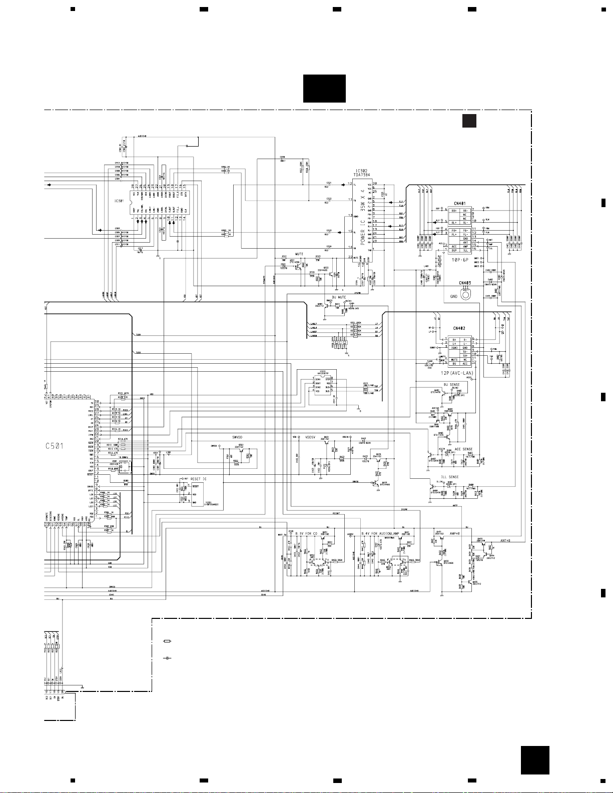
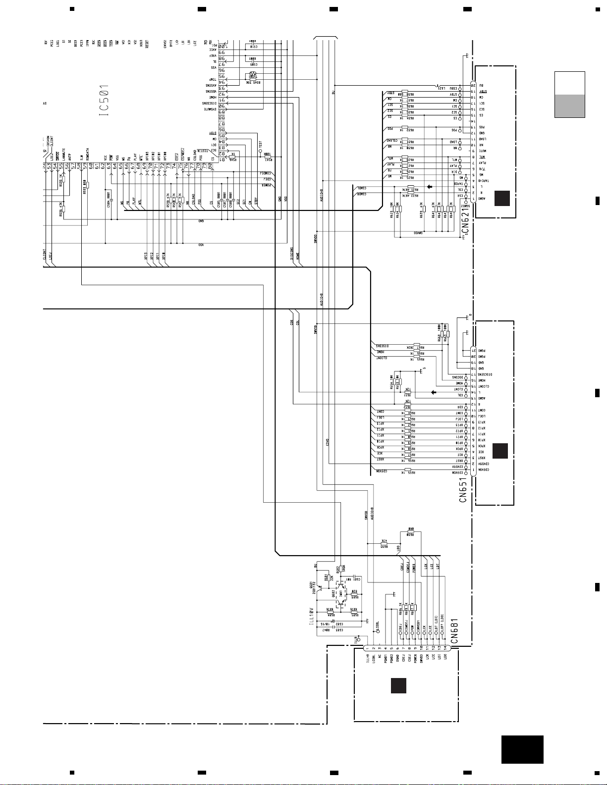
89
SYSMUTE
XOUT
XIN
2
4
3
SYSTEM µ-COM
IC 501(2/2)
PD5708A
ANT1
TU5V
TU8V
ANT
E
CN621
MAIN UNIT
13
X501
15
14
1
V
TUN L
CDL
TAPE L
41
SYSPOW
fR
CSLOAD
POS
ES
SC2
66
77
78
80
82
BU
65
MS
83
SC1
85
84
CM
stby
f/R
POS
ES
SC2
SC1
CM
stby
CSLOAD
Q201
54
swvdd
SW
AUD
Q681
Q682
BU
ILM
58
CDVD
53
50
90
91
51
LOEJ
CONT
DSCSNS
HOME
CD5VON
BEEP
24
LANL
5
pow
63
IC 3
EEPROM
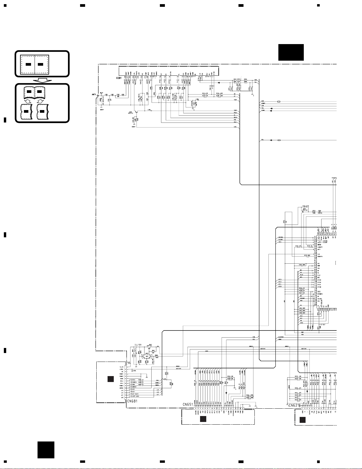
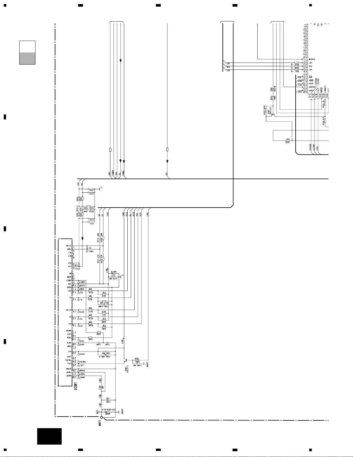
FM/AM TUNER UNIT
28
27
FM/AM 1ST IF 10.7MHz
T51 Q51 CF51
CF52 CF53
IC1
MIXER, IF AMP, DET.
6
21
18
LDET
COMP
222510 14 12 15 16 8 13 2 3 4
CF202
VDD
VCC
DI/DO
CE2CKCE1
SDBWSLFMSD
NL1
NL2
IC 2 FM MPX
AMANT
FMANT
ATT
ATT
AMRF
FMRF
RF ADJ
ANT2 ADJ
X901
10.25MHz
ANT1 ADJ
LOCL
23
LOCH
AMDET
MPXREF 41kHz
AM 2ND IF
450kHz
19
CREQ
11
DGND
1
STIND
L ch
5
R ch
924
AMDET
FMLOCL
20177
AM
IN
NC
WC
26
RFGND
stby
B.U
MUTE
LOAD
5
1
4
2
1
3
11
9
20
19
D
DECK UNIT
IC251
HA12228F
IC351
PA2020A
EQ AMP
MECHANISM
DRIVER
CN251
CN252
CN254
CN255
CN253
6
16
MS
Lch
20
FWD
L-ch
REV
L-ch
37
36
39
18
19
17
8
7
10
CN256
S1
LOAD
S2
MODE
EGN1
REEL
SENSE
M
M
M2
SUB
MOTOR
M1
MAIN
MOTOR
5
2
1
E
SENSOR UNIT
6
5
17
f/R
15
13
13
11
POS
NES
18
17
16
15
SC1
CM
16
14
SC2
3
11
20
19
6
5
15
13
18
17
16
3
1
5
6
3
1
5
6
A
C
CN701
Q101
CONTROL UNIT
M
LASER
DIODE
MONITOR
DIODE
CLAMP
SENSE
DISC
SENSE
FOCUS ACT.
SPINDLE
MOTOR
M
CARRIAGE
MOTOR
LOAD/
TRACKING ACT.
LD-
MD
FO+
TO+
15
5
1
4
PICKUP UNIT(SERVICE) (P9)
HOLOGRAM
UNIT
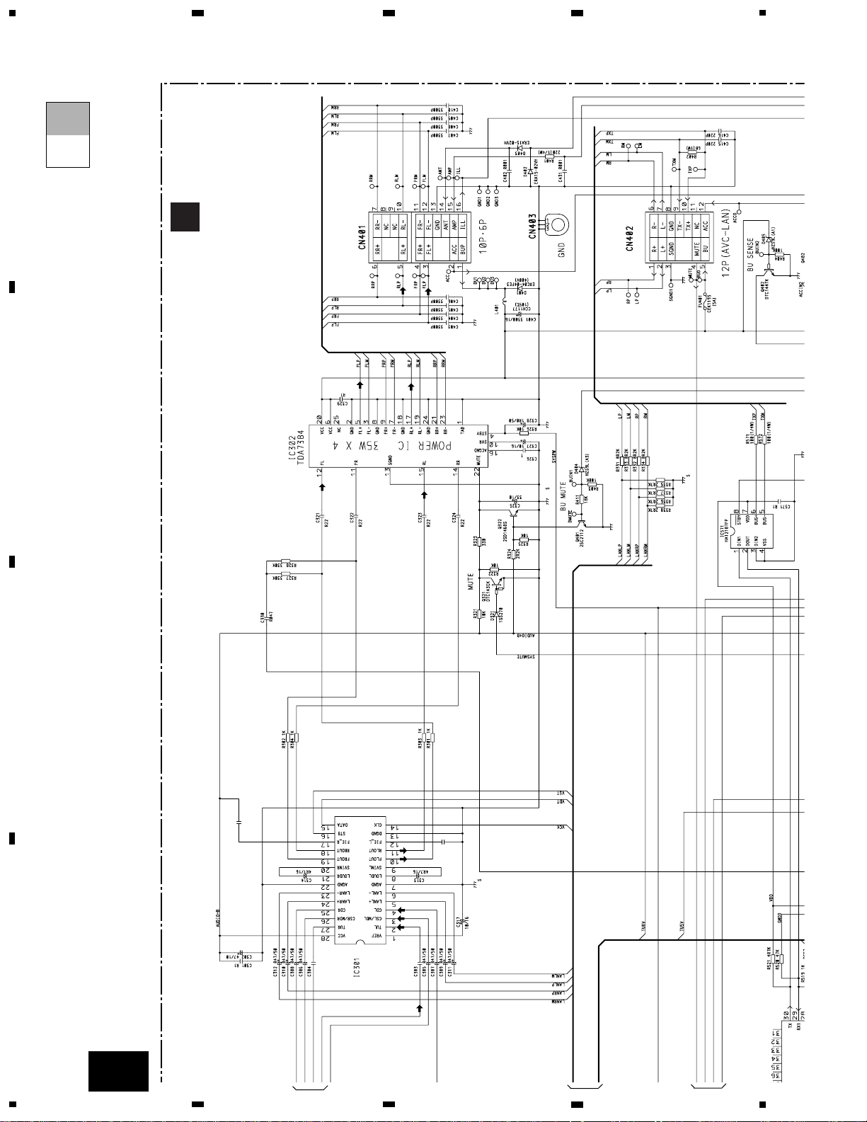
IC 401
BA5996FM
IC 201
TC9495FP
IC 701
BA05SFP
+5V REGULATOR
SERVO
CONTROL,
DSP,
LPF, DAC
CD
DRIVER
17
DSCSNS
2
VD
VD
VDD
11
CONT
10
LOEJ
14
L-OUT
1
CD5VON
CN101
TOP
FOP
16
SOP
15
SOM
17
LCOP
18
LCOM
22
1
2
LOEJ
78
85
L_OUT
79
9
MUTE
12
FOP
TD/FD
AC,BD
F,E
SD/MD
38
RFI
43
FEI
4
14
TOP
S901
HOME
12EJ
SENSE
8EJ
SENSE
HOME
16
LD+
14
VDD
9
LDO
8
MDI
IC 101
TA2153FN
RFRPIN
FEO
TEO
24
16
14
46
TEI
RF-AMP
17
2
11
10
14
1
16
CN651
10
FH-M2017ZT
A
1
234
B
C
D
12
34
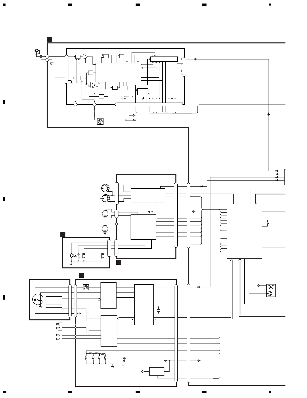
3. BLOCK DIAGRAM AND SCHEMATIC DIAGRAM
3.1 BLOCK DIAGRAM
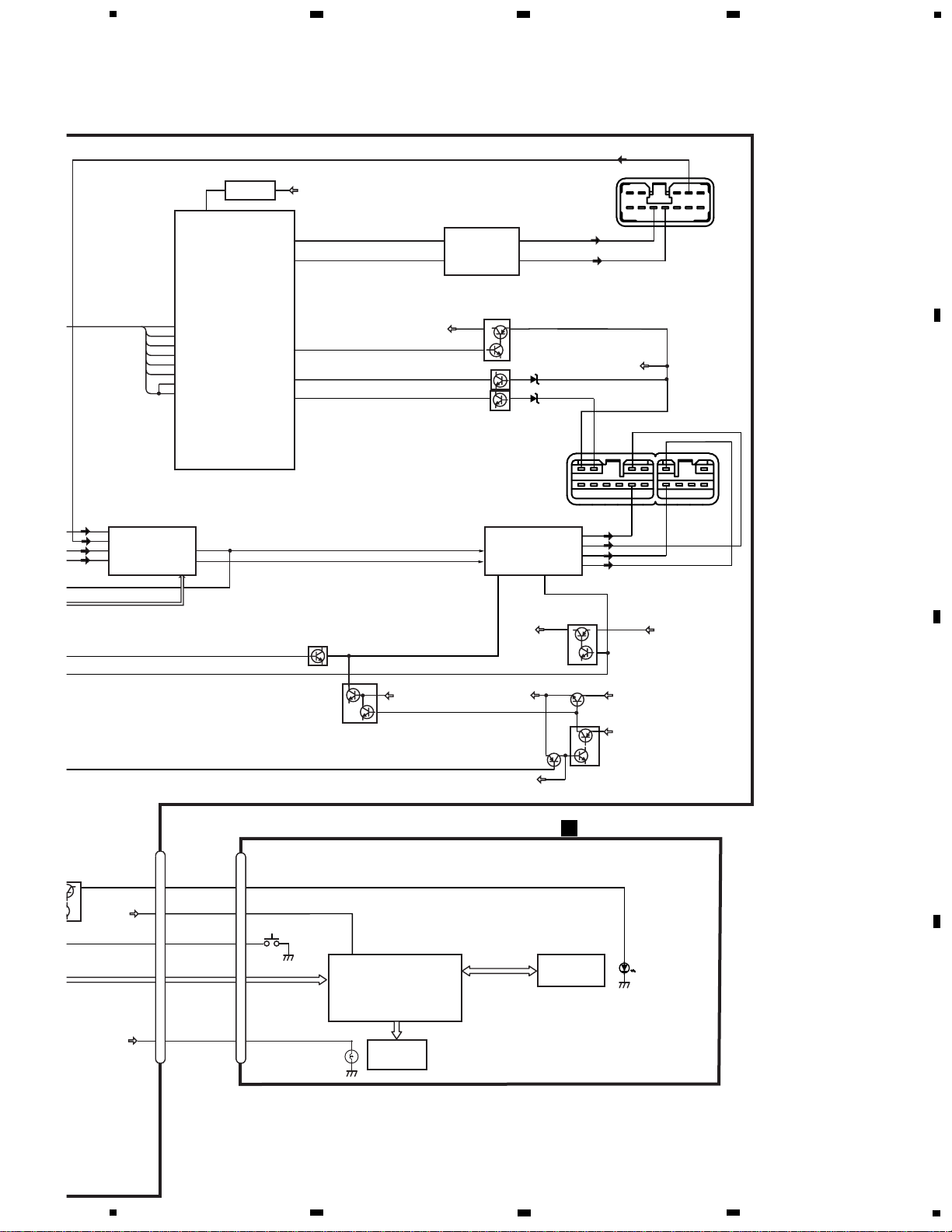
B
12
1
bsen
asen
VDD
BU
ST
20
19
SD
SL
PCE1
pck
PCE2
PDI
PDO
10
FL
11
RL
3
5
19
17
FL—
FL+
RL—
RL+
ACC
26
25
97
TUL
2
CDL
4
CSL
3
23
2
28
100
1
FLIN
12
RLIN
15
22 4
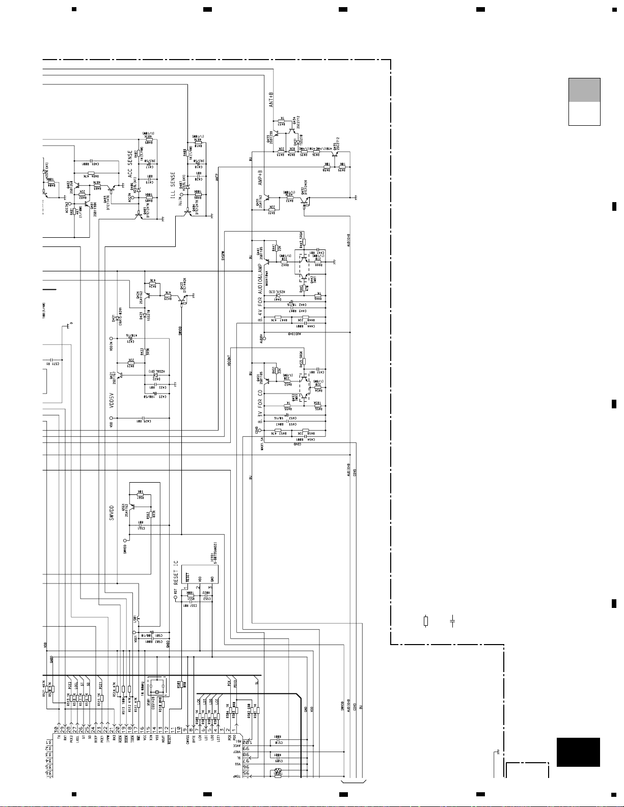
SYSTEM µ-COM
RESET
POWER AMP
IC 501(1/2)
PD5708A
IC 301
PML003AM
IC 551
S-80735ANDZI
IC 302
TDA7384
reset
CDVD
Q451
Q402
SYSPW
ELECTRONIC VOLUME/
SOURCE SELECTOR
STBYMUTE
CN681
KEYBOARD UNIT
2
VST,VCK,VDT
AUDIO+B
BU
Q441
Q442
BU
ACC
RL+
FL+
RL-
FL-
Q321
MUTE
CN901
Q403
Q452
VDCONT
49
AUDIO+B
Q322
Q401
BU MUTE
BU
Q421
Q424
Q423
BU
VDD
SWVDD
Q561
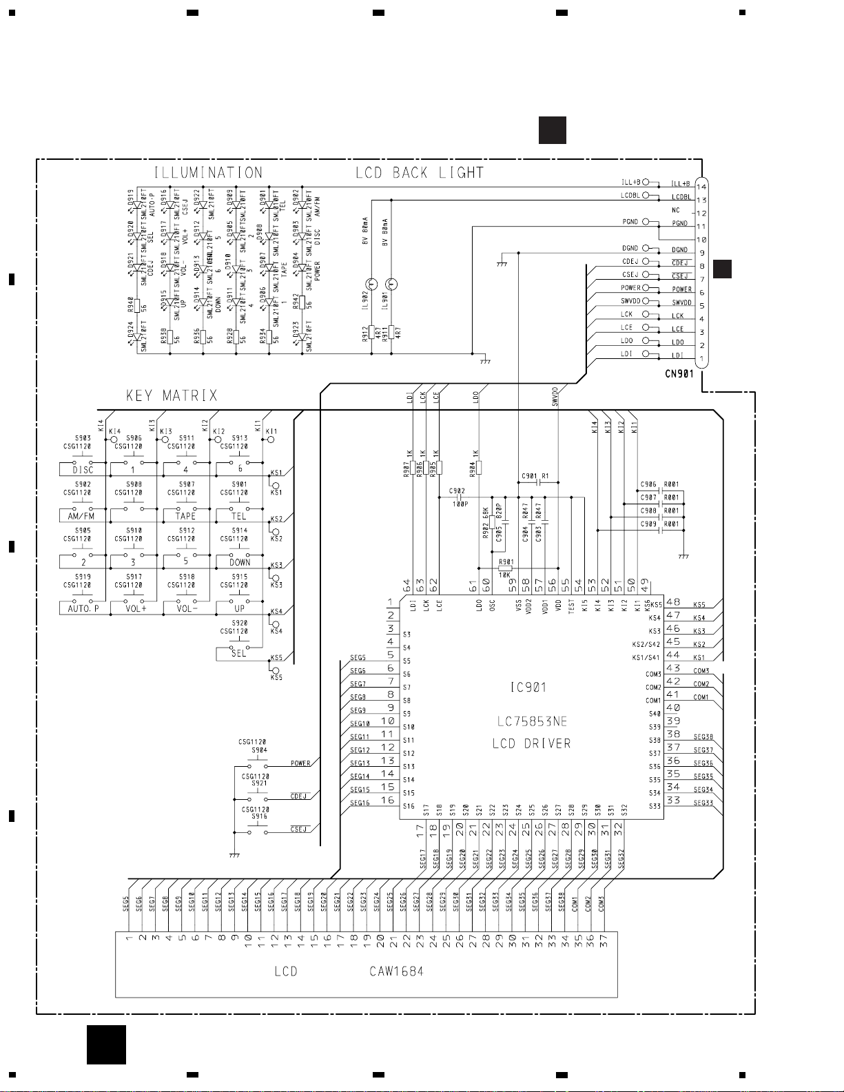
IC 901
LC75853NE
LCD DRIVER
KEY MATRIX
KEY DATA
VDD
56
LCD
SWVDD
AUDIO+B
Q681
LCK,LCE,LDO,LDI
L+
IC 571
HA12187FP
BUS+
6
BUS-
5
2
1
29
30
DOUT
DIN1
RXI
TX
TX+
TX-
BU
LANL
5
LANL
1
2
10
14
13
5
S904
POWER
9
6
ILL+B
SWVDD
LCDBL
CN401
CN402
11
FH-M2017ZT
5
6
7
8
A
B
C
D
5
6
7
8
12
FH-M2017ZT
A
1
234
B
C
D
12
34
A
A-aA-a A-b A-b
A-a
A-b
A-b
A-a
Large size
SCH diagram
Guide page
Detailed page
3.2 OVERALL CONNECTION DIAGRAM(GUIDE PAGE)
Note: When ordering service parts, be sure to refer to “EXPLODED VIEWS AND PARTS LIST” or “ELECTRICAL
PARTS LIST”.
A-a
R353
0R0
R354
0R0
PD
47K
1R5K
1R5K
10K
56K
2200P
5600P
R018
R018
4700P
4700P
TUNER: -30dBs
CD: 4.2dBs
TAPE: -7.3dBs
D
CN251
C
CN701
B
CN901
FM/AM TUNER UNIT
DECK U
CONTROL UNIT
13
FH-M2017ZT
5
6
7
8
A
B
C
D
5
6
7
8
A-b
A
600µH
>
PML003AM
D5708A
R22
R22
R015
C316
R015
C315
Decimal points for resistor
and capacitor fixed values
are expressed as :
2.2 2R2
0.022 R022
←
←
The > mark found on some component parts indicates
the importance of the safety factor of the part.
Therefore, when replacing, be sure to use parts of
identical designation.
Symbol indicates a resistor.
No differentiation is made between chip resistors and
discrete resistors.
NOTE :
Symbol indicates a capacitor.
No differentiation is made between chip capacitors and
discrete capacitors.
BUS DRIVER
E-VOLUME
MAIN UNIT
E-VOL input
AVC-LAN: -3.8dBs
CD,MD: -3.8dBs
TAPE:-9.8dBs
FM:-30.7dBs
FM: -11.6dBs
FM: 14.4dBs
AVC-LAN: 8.2dBs
A
NIT
14
FH-M2017ZT
A
1
234
B
C
D
12
34
R353
0R0
R354
0R0
47K
1R5K
1R5K
56K
2200P
5600P
R018
R018
4700P
4700P
TUNER: -30dBs
FM/AM TUNER UNIT
A-a
A-b
A-a
1
2
3
4
5
15
FH-M2017ZT
5
6
7
8
A
B
C
D
5
6
7
8
PD5708A
10K
CD: 4.2dBs
TAPE: -7.3dBs
D
CN251
C
CN701
B
CN901
DECK UNIT
CONTROL UNIT
A-a
A-b
A-a
6
16
FH-M2017ZT
A
1
234
B
C
D
12
34
600µH
>
PML003AM
R22
R22
R015
C316
R015
C315
BUS DRIVER
E-VOLUME
MAIN UNIT
E-VOL input
AVC-LAN: -3.8dBs
CD,MD: -3.8dBs
TAPE:-9.8dBs
FM:-30.7dBs
FM: -11.6dBs
FM: 14.4dBs
AVC-LAN: 8.2dBs
A
A-a
A-b
A-b
1
2
3
4
5
17
FH-M2017ZT
5
6
7
8
A
B
C
D
5
6
7
8
Decimal points for resistor
and capacitor fixed values
are expressed as :
2.2 2R2
0.022 R022
←
←
The > mark found on some component parts indicates
the importance of the safety factor of the part.
Therefore, when replacing, be sure to use parts of
identical designation.
Symbol indicates a resistor.
No differentiation is made between chip resistors and
discrete resistors.
NOTE :
Symbol indicates a capacitor.
No differentiation is made between chip capacitors and
discrete capacitors.
A-a
A-b
A-b
6
18
FH-M2017ZT
A
1
234
B
C
D
12
34
10V
8.4V
5V
CN681
A
PWR
CD EJECT
TAPE
EJECT
CEL1588
CEL1588
EQ
CD IN 2
CD IN 1
EQ
CS IN 2
CS IN 1
3.3 KEYBOARD UNIT
B
KEYBOARD UNIT
B

19
FH-M2017ZT
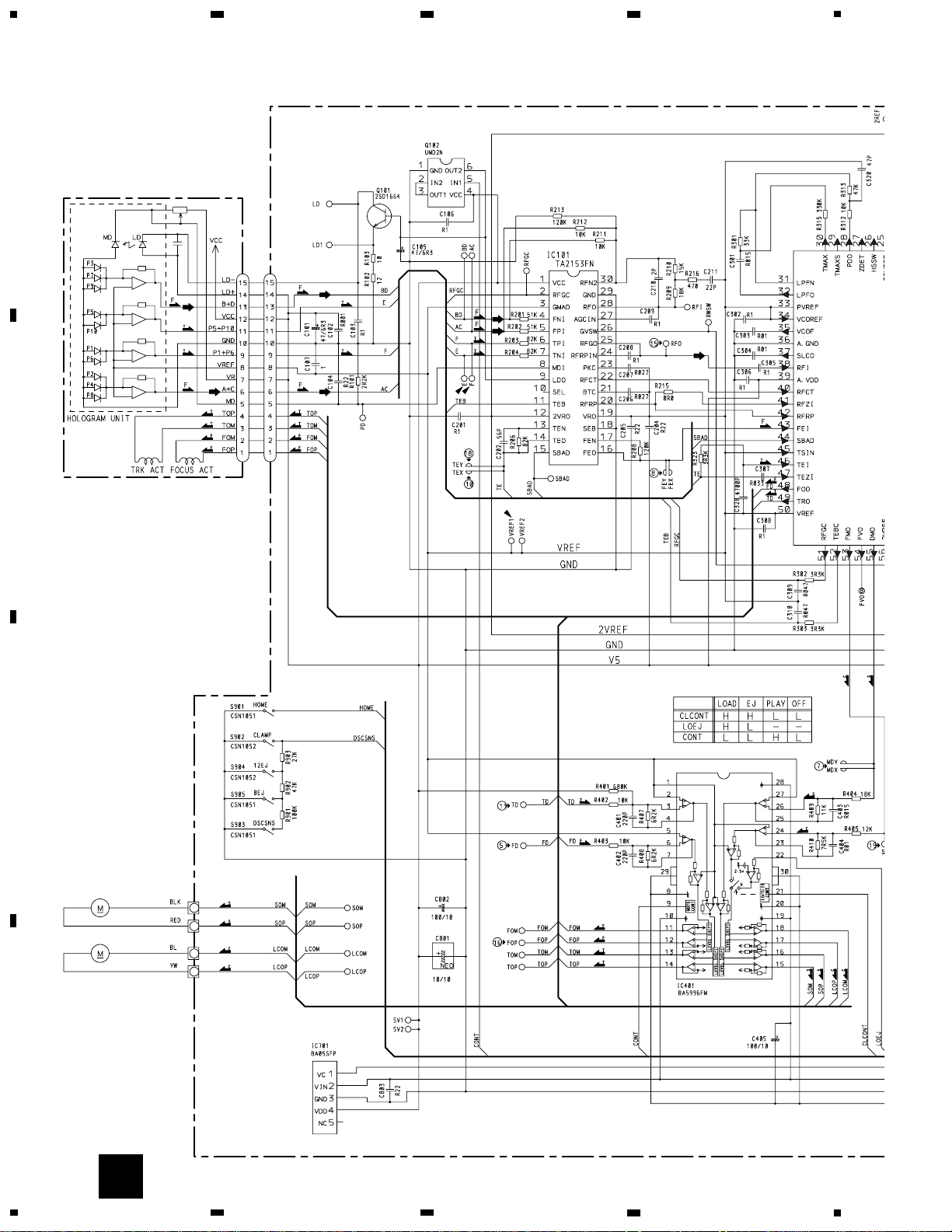
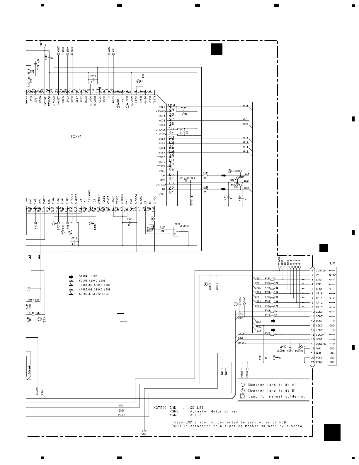
3.4 CD MECHANISM MODULE
20
FH-M2017ZT
A
1
234
B
C
D
12
34
M1 CXB6007
M2 CXB5903
LOADING/CARRIAGE
SPINDLE
RF AMP
ACT/MOTOR DRIVER
5V REGULATOR
CN101
C
PICKUP UNIT(SERVICE)(S9)
21
FH-M2017ZT
5
6
7
8
A
B
C
D
5
6
7
8
C
16.934MHz
SERVO CONTROL/DSP/DAC/LPF
CN701
TC9495FP
SWITCHES:
CONTROL UNIT
S901 : HOME SWITCH.....ON-OFF
S902 : CLAMP SWITCH....ON-OFF
S903 : DSCSNS SWITCH....ON-OFF
S904 : 12EJ SWITCH....ON-OFF
S905 : 8EJ SWITCH....ON-OFF
The underlined indicates the switch position.
CONTROL UNIT
C
A
CN651

22
FH-M2017ZT
@ CH1:BCK 2V/div.
During "Play"
1 CH1:DSCSNS 5V/div.
2 CH2:CLCONT 5V/div.
3 CH3:LOEJ 5V/div.
4 CH4:VD 10V/div.
When loading (8 cm CD)
500ms/div.
5 CH1:FD 500mV/div.
6 CH2:FOK 5V/div.
7 CH3:MD 5V/div.
When setting up "Source On"
500ms/div.
8 CH1:FE 500mV/div.
9 CH2:FOON 5V/div.
When setting up "Source On"
500ms/div.
5 CH1:FD 500mV/div.
6 CH2:FOK 5V/div.
7 CH3:MD 5V/div.
Magnified drawing for "time"
100ms/div.
1 CH1:DSCSNS 5V/div.
2 CH2:CLCONT 5V/div.
3 CH3:LOEJ 5V/div.
4 CH4:VD 10V/div.
When loading (12 cm CD)
Ref. :
GND
Mode :
Normal
Ref. :
GND
Mode :
Normal
Ref. :
VREF
Mode :
Normal
Ref. :
VREF
Mode :
Normal
Ref. :
VREF
Mode :
Normal
Ref. :
VREF
Mode :
Normal
Ref. :
VREF
Mode :
Normal
Ref. :
VREF
Mode :
Normal
Ref. :
VREF
Mode :
Normal
Ref. :
VREF
Mode :
Test
Ref. :
VREF
Mode :
Normal
Ref. :
VREF
Mode :
Normal
500ms/div.
0 CH1:TE 500mV/div.
8 CH2:FE 500mV/div.
When setting up "Source On"
200ms/div.
1µs/div.
# CH1:LRCK 2V/div.
$ CH2:DOUT 2V/div.
During "Play"
10µs/div.
7 CH1:MD 500mV/div.
During "Play"
10µs/div.
% CH1:RFO 500mV/div.
During "Play"
0.5µs/div.
% CH1:RFO 500mV/div.
0 CH2:TE 500mV/div.
During "Tracking Open"
2ms/div.
8 CH1:FE 500mV/div.
5 CH2:FD 500mV/div.
0 CH3:TE 500mV/div.
! CH4:TD 500mV/div.
During "Play"
1ms/div.
- Waveforms
Note:1. The encircled numbers denote measuring pointes in the circuit diagram.
2. Reference voltage
VREF:2.1V
 Loading...