

PIONEER FH-2427 Service Manual
PIONEER CORPORATION 4-1, Meguro 1-Chome, Meguro-ku, Tokyo 153-8654, Japan
PIONEER ELECTRONICS (USA) INC. P.O.Box 1760, Long Beach, CA 90801-1760 U.S.A.
PIONEER EUROPE NV Haven 1087 Keetberglaan 1, 9120 Melsele, Belgium
PIONEER ELECTRONICS ASIACENTRE PTE.LTD. 253 Alexandra Road, #04-01, Singapore 159936
C PIONEER CORPORATION 2002
K-ZZB. AUG. 2002 Printed in Japan
ORDER NO.
CRT2887
RECEIVER ASSY RADIO
FH-2427ZF X1H/UC
FORD
- This service manual should be used together with the manual(s) listed below.
For the parts numbers, adjustments, etc. which are not shown in this manual, refer to the following
manual(s).
Model No. Order No. Mech. Module Remarks
FH-2077ZF/X1H/UC CRT2822
CX-597 CRT1829 S7
CD Mech. Module:Circuit Description, Mech. Description, Disassembly
CX-1011 CRT2406 3L
Cassette Mech. Module:Mech.Description, Disassembly
VEHICLE DESTINATION PRODUCED AFTER PART No. ID No. PIONEER MODEL No.
F150 Super Crew U.S.A., CANADA July 2002 3L3T-18C868-BB FH-2427ZF/X1H/UC
Harley Truck
1
234
12
34
F
E
D
C
B
A
FH-2427ZF/X1H/UC
EXPLODED VIEWS AND PARTS LIST
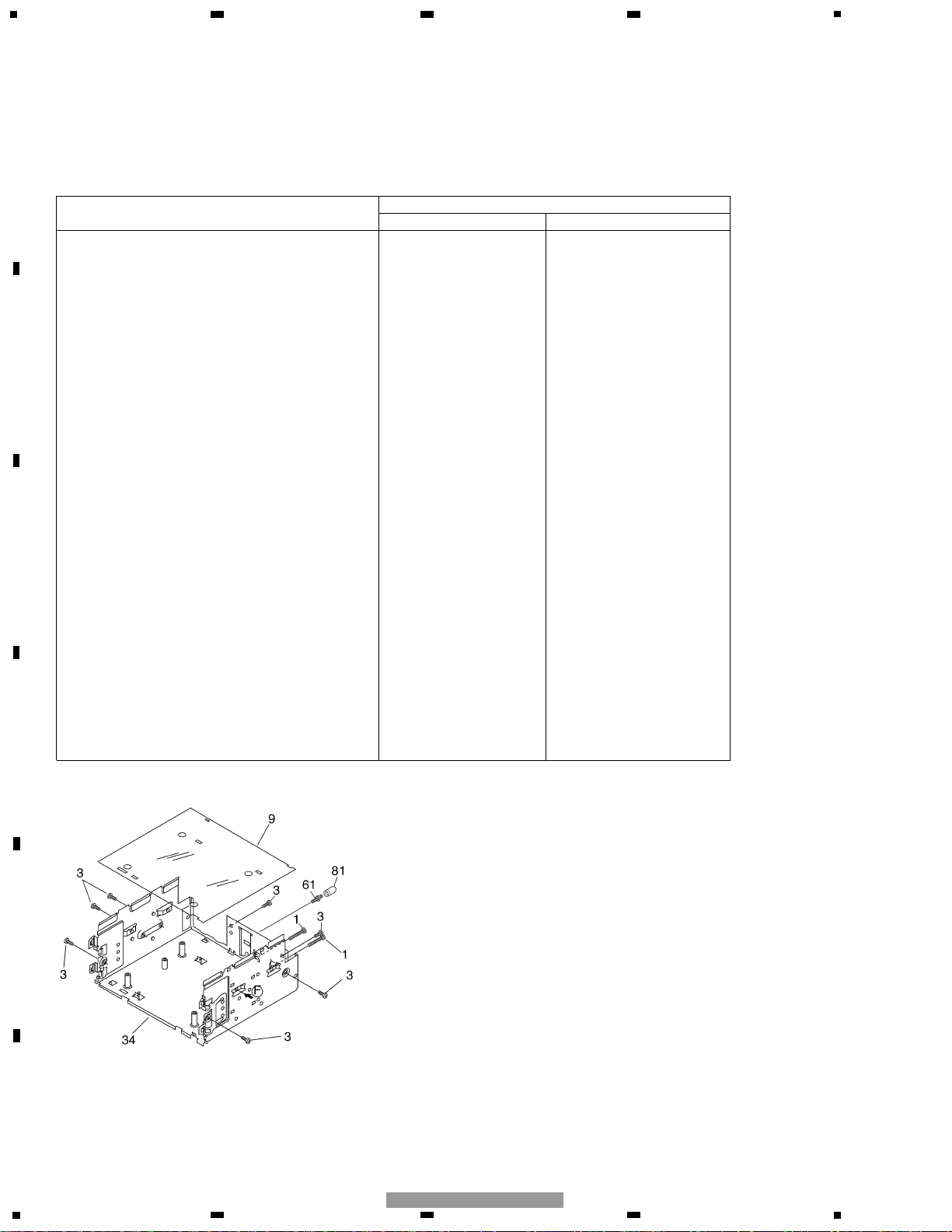
EXTERIOR (Page 4)
- EXTERIOR SECTION PARTS LIST *:Non spare part
Part No.
Mark No. Description FH-2077ZF/X1H/UC FH-2427ZF/X1H/UC
8 Case HNB2059 HNB0206
11 Rail Guide HNV4897 Not used
12 Mother Unit HWM0072 HWM0090
25 Compound Unit HWM0074 HWM0091
34 Chassis Unit HXA8841 HXA0390
36 Knob Assy CXB8377 CXB9536
37 Grille Unit CXB9218 CXB9535
40 Button(EJ) CAC7446 CAC7755
41 Keyboard Unit HWM8124 HWM0092
45 Button(AM) CAC7447 CAC7756
46 Button(FM) CAC7448 CAC7757
48 Button(MUTE) CAC7449 CAC7758
61 Screw HBA1404 CBA1138
67 Button(TAPE) CAC7450 CAC7759
68 Button(CD) CAC7451 CAC7760
69 Button(AUTO,RDS) CAC7452 CAC7761
70 Button(TUNE) CAC7453 CAC7762
71 Button(EJ) CAC7454 CAC7763
72 Button(BASS,TREB) CAC7455 CAC7764
73 Button(BAL,FADE) CAC7456 CAC7765
74 Button(SEL) CAC7457 CAC7766
75 Button(1,2) CAC7458 CAC7767
76 Button(3,4) CAC7459 CAC7768
77 Button(5,6) CAC7460 CAC7769
78 Door CAT2339 *HAT1760
81 Bush Not used CNV4955
3
5
6
7
8
F
E
D
C
B
A
5
6
7
8
FH-2427ZF/X1H/UC
ELECTRICAL PARTS LIST(Page 54)
Mother Unit
Part No.
Symbol and Description FH-2077ZF/X1H/UC FH-2427ZF/X1H/UC
IC602 IC PE5315A PE5250A
R364 RS1/10S152J RS1/10S122J
R1227 RS1/16S512J RS1/16S562J
R1249 RS1/10S431J RS1/10S561J
C1205 CKSRYB393K25 CKSRYB333K25
C
F
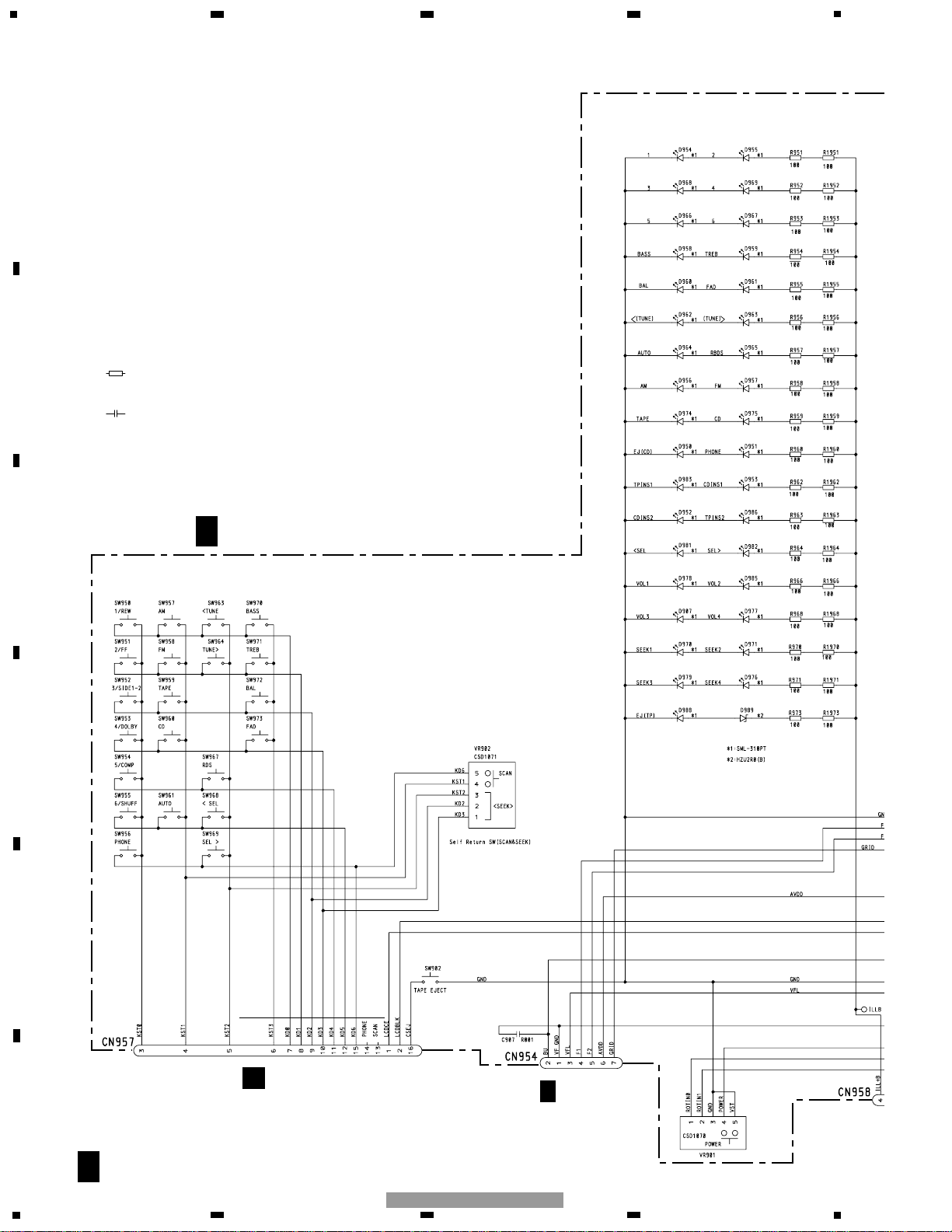
KEYBOARD UNIT
C
F
CN953
KEY MATRIX CIRCUIT
BUTTON ILLUMINATION
SWITCH CIRCUIT
A
F
F
CN1051
Decimal points for resistor
and capacitor fixed values
are expressed as :
2.2 2R2
0.022 R022
←
←
Symbol indicates a resistor.
No differentiation is made between chip resistors and
discrete resistors.
NOTE :
Symbol indicates a capacitor.
No differentiation is made between chip capacitors and
discrete capacitors.
4
1
234
12
34
F
E
D
C
B
A
FH-2427ZF/X1H/UC
SCHEMATIC DIAGRAM
KEYBOARD UNIT
 Loading...