

PIONEER FH-2327 Service Manual

PIONEER CORPORATION 4-1, Meguro 1-Chome, Meguro-ku, Tokyo 153-8654, Japan
PIONEER ELECTRONICS (USA) INC. P.O.Box 1760, Long Beach, CA 90801-1760 U.S.A.
PIONEER EUROPE NV Haven 1087 Keetberglaan 1, 9120 Melsele, Belgium
PIONEER ELECTRONICS ASIACENTRE PTE.LTD. 253 Alexandra Road, #04-01, Singapore 159936
C PIONEER CORPORATION 2002
K-ZZB. AUG. 2002 Printed in Japan
ORDER NO.
CRT2886
RECEIVER ASSY RADIO
FH-2327ZF X1H/UC
FORD
- This service manual should be used together with the manual(s) listed below.
For the parts numbers, adjustments, etc. which are not shown in this manual, refer to the following
manual(s).
Model No. Order No. Mech. Module Remarks
FH-2076ZF/X1H/UC CRT2025
CX-597 CRT1829 S7
CD Mech. Module:Circuit Description, Mech. Description, Disassembly
CX-1011 CRT2406 3L
Cassette Mech. Module:Mech.Description, Disassembly
- Dolby noise reduction manufactured under license from Dolby Laboratories Licensing Corporation.
"Dolby" and the double-D symbol are trademarks of Dolby Laboratories Licensing Corporation.
VEHICLE DESTINATION PRODUCED AFTER PART No. ID No. PIONEER MODEL No.
F150 Trucks U.S.A., CANADA July 2002 3L3T-18C868-AB FH-2327ZF/X1H/UC
For details, refer to "Important symbols for good services".
2
1
234
12
34
F
E
D
C
B
A
FH-2327ZF/X1H/UC
[ Important symbols for good services ]
In this manual, the symbols shown-below indicate that adjustments, settings or cleaning should be made securely.
When you find the procedures bearing any of the symbols, be sure to fulfill them:
2. Adjustments
To keep the original performances of the product, optimum adjustments or specification confirmation is indispensable.
In accordance with the procedures or instructions described in this manual, adjustments should be performed.
3. Cleaning
For optical pickups, tape-deck heads, lenses and mirrors used in projection monitors, and other parts requiring cleaning,
proper cleaning should be performed to restore their performances.
5. Lubricants, glues, and replacement parts
Appropriately applying grease or glue can maintain the product performances. But improper lubrication or applying
glue may lead to failures or troubles in the product. By following the instructions in this manual, be sure to apply the
prescribed grease or glue to proper portions by the appropriate amount.For replacement parts or tools, the prescribed
ones should be used.
4. Shipping mode and shipping screws
To protect the product from damages or failures that may be caused during transit, the shipping mode should be set or
the shipping screws should be installed before shipping out in accordance with this manual, if necessary.
1. Product safety
You should conform to the regulations governing the product (safety, radio and noise, and other regulations), and
should keep the safety during servicing by following the safety instructions described in this manual.
3
5
6
7
8
F
E
D
C
B
A
5
6
7
8
FH-2327ZF/X1H/UC
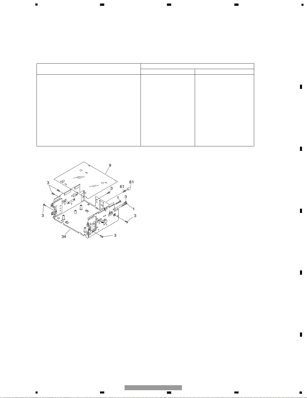
EXPLODED VIEWS AND PARTS LIST
EXTERIOR (Page 3)
- EXTERIOR SECTION PARTS LIST
Part No.
Mark No. Description FH-2076ZF/X1H/UC FH-2327ZF/X1H/UC
6 Cassette Mechanism Module EXK3285 EXK4260
8 Case HNB2059 HNB0206
9 Insulator HNM4745 HNM0089
11 Rail Guide HNV4897 Not used
12 Mother Unit HWM4717 HWM0088
18 Connector(CN702) HKS1730 CKS3568
25 Compound Unit HWM5467 HWM0089
34 Chassis Unit HXA8841 HXA0390
61 Screw HBA1404 CBA1138
81 Bush Not used CNV4955
Mother Unit (Service) HXX1321 Not used

For grease application, refer to the service manual for CX-1011 (CRT2406).
4
1
234
12
34
F
E
D
C
B
A
FH-2327ZF/X1H/UC
CASSETTE MECHANISM MODULE
I
F
J
F

5
5
6
7
8
F
E
D
C
B
A
5
6
7
8
FH-2327ZF/X1H/UC
1 Screw BSZ20P040FMC
2 Washer CBF1037
3 Washer CBG1003
4 Screw EBA1028
5 Screw CBA1037
6 Spring EBH1653
7 Spring EBH1642
8 Spring EBH1641
9 Spring EBH1626
10 Spring EBH1627
11 Spring EBH1648
12 Cord EDD1024
13 Photo-reflector(Q101) EGN1004
14 Arm ENC1526
* 15 Lever ENC1544
16 Lever ENC1543
17 Arm ENC1532
18 Frame ENC1533
19 Holder ENC1547
20 Gear ENC1535
21 Arm ENC1550
22 Roller ENR1040
23 Belt ENT1027
24 Collar ENV1508
25 Arm ENV1539
26 Arm ENV1540
27 Gear ENV1569
28 Gear ENV1547
29 Gear ENR1044
30 Worm Wheel ENV1559
31 Lever ENV1551
32 Flywheel ENV1554
33 PCB ENP1196
34 Switch(S101,S102,S103) ESG1007
35 Deck Unit EWM1031
36 Plug(CN251) CKS3540
37 Gathering PCB ENX1066
38 Motor Unit(M1) EXA1491
39 Motor EXM1028
40 Head Assy(HD1) EXA1594
41 Arm ENC1537
42 Screw JGZ20P025FNI
43 Guide ENC1545
44 Chassis Unit EXA1609
45 Pinch Holder Unit EXA1608
46 Pinch Roller ENV1518
47 Pinch Holder Unit EXA1607
48 Pinch Roller ENV1518
49 Reel Unit EXA1625
50 Head Base Unit EXA1611
51 Lever Unit EXA1587
52 Gear Unit EXA1596
53 Motor Unit(M2) EXA1623
54 Washer HBF-179
55 Spring EBH1537
56 Worm Gear ENV1564
57 Spring EBH1654
58 •••••
59 •••••
60 Tube ENM1039
61 •••••
62 Spring EBH1545
63 Sensor Unit EWM1036
Mark No. Description Part No. Mark No. Description Part No.
- CASSETTE MECHANISM MODULE SECTION PARTS LIST
NOTE:
- Parts marked by “*” are generally unavailable because they are not in our Master Spare Parts List.
- Screws adjacent to ∇ mark on the product are used for disassembly.
- For the applying amount of lubricants or glue, follow the instructions in this manual.
( In the case of no amount instructions, apply as you think it appropriate.)
6
1
234
12
34
F
E
D
C
B
A
FH-2327ZF/X1H/UC
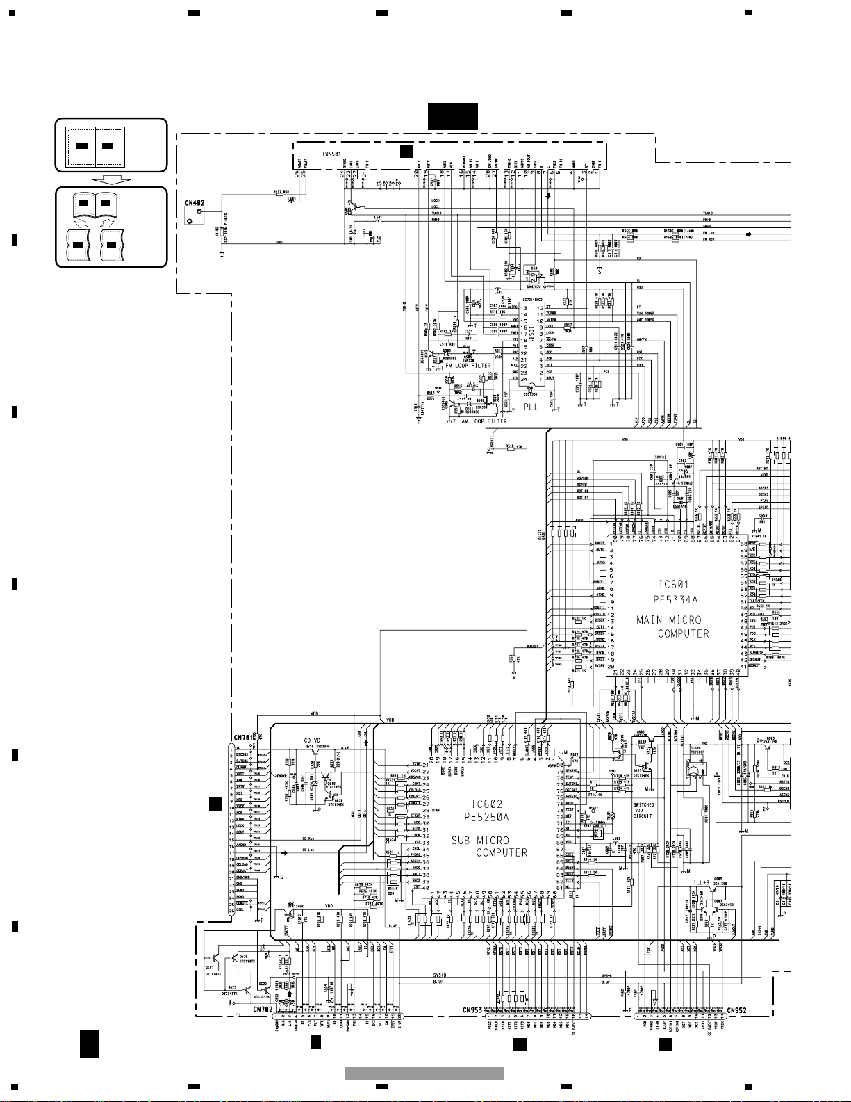
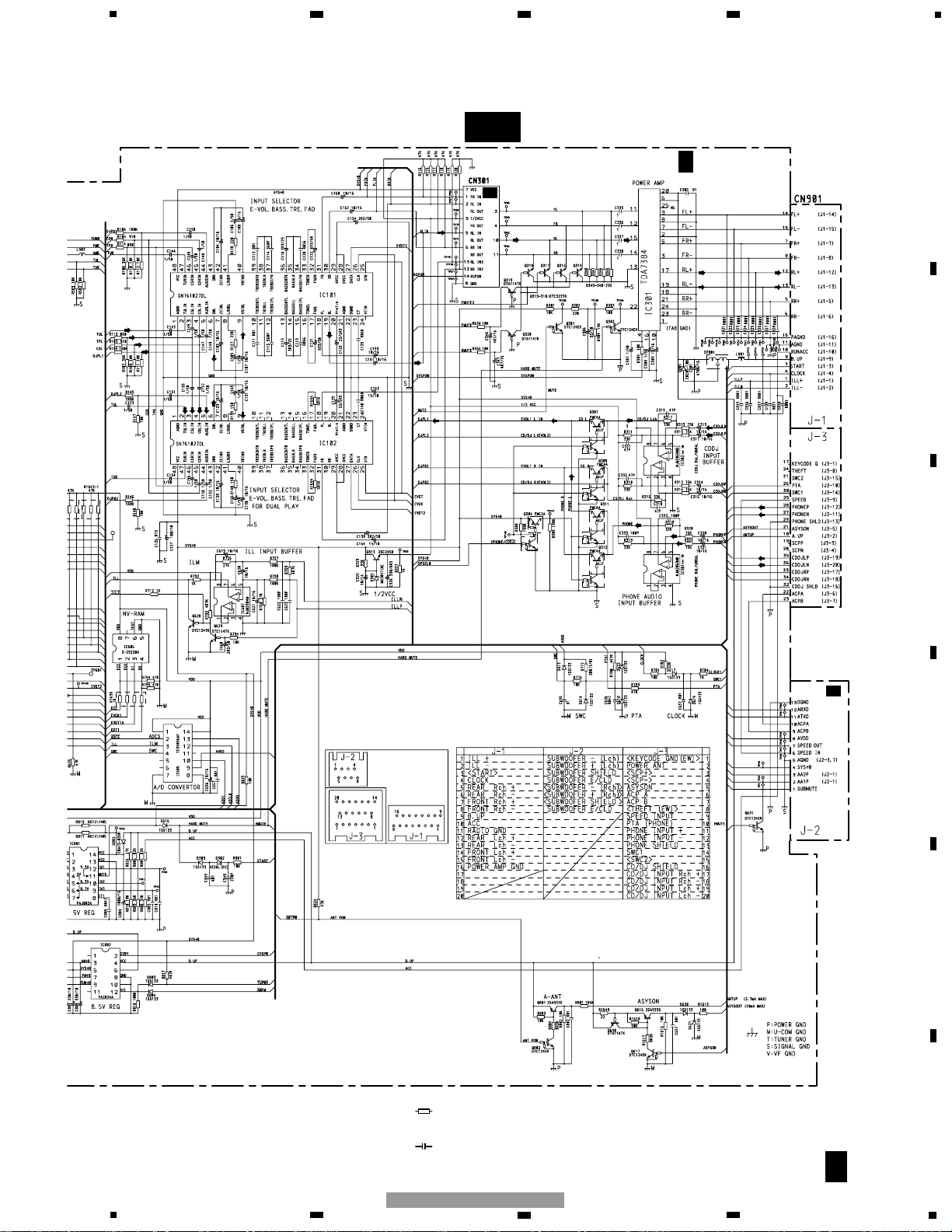
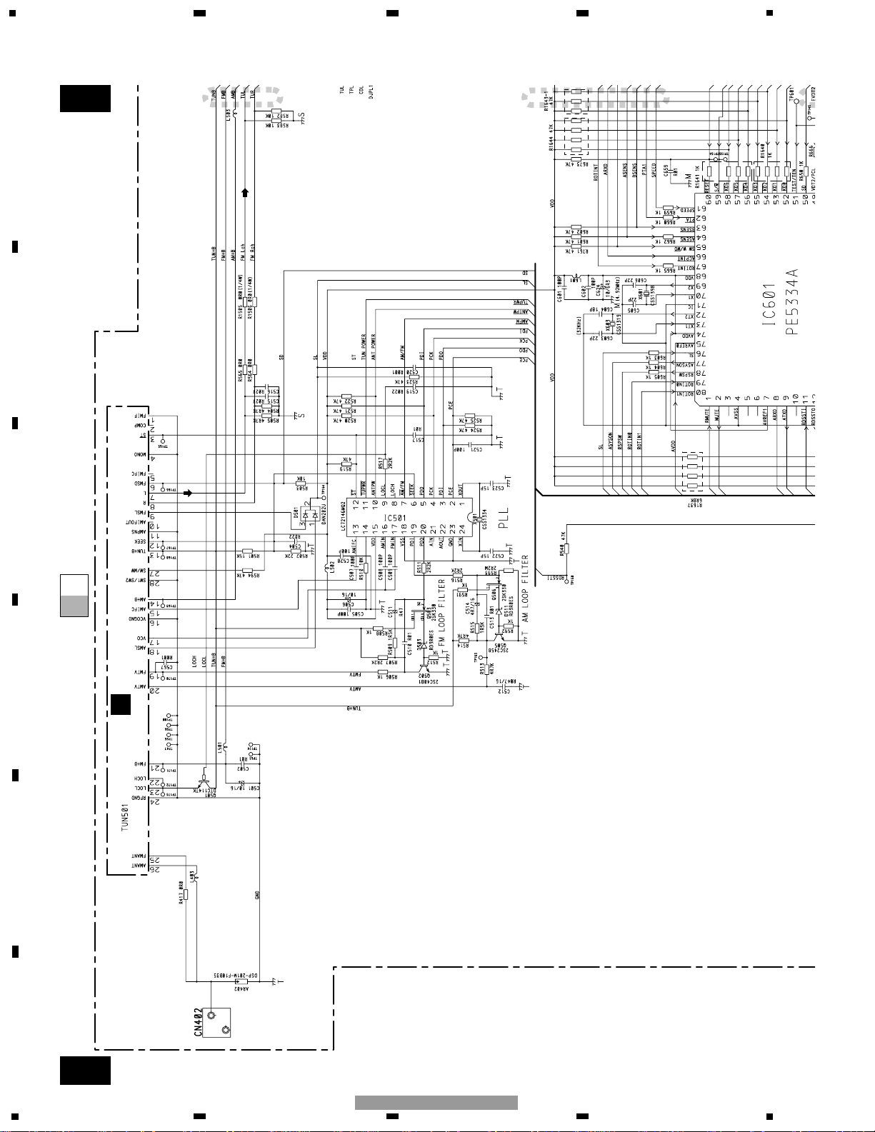
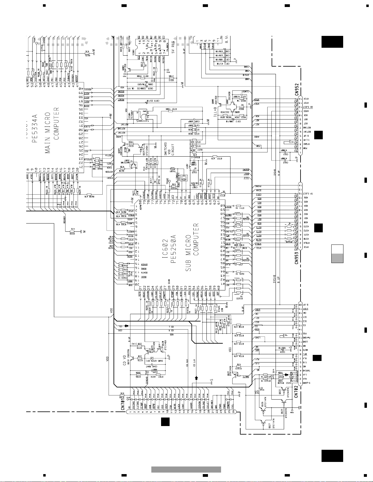
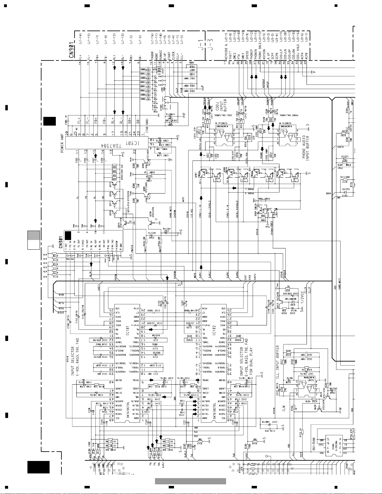
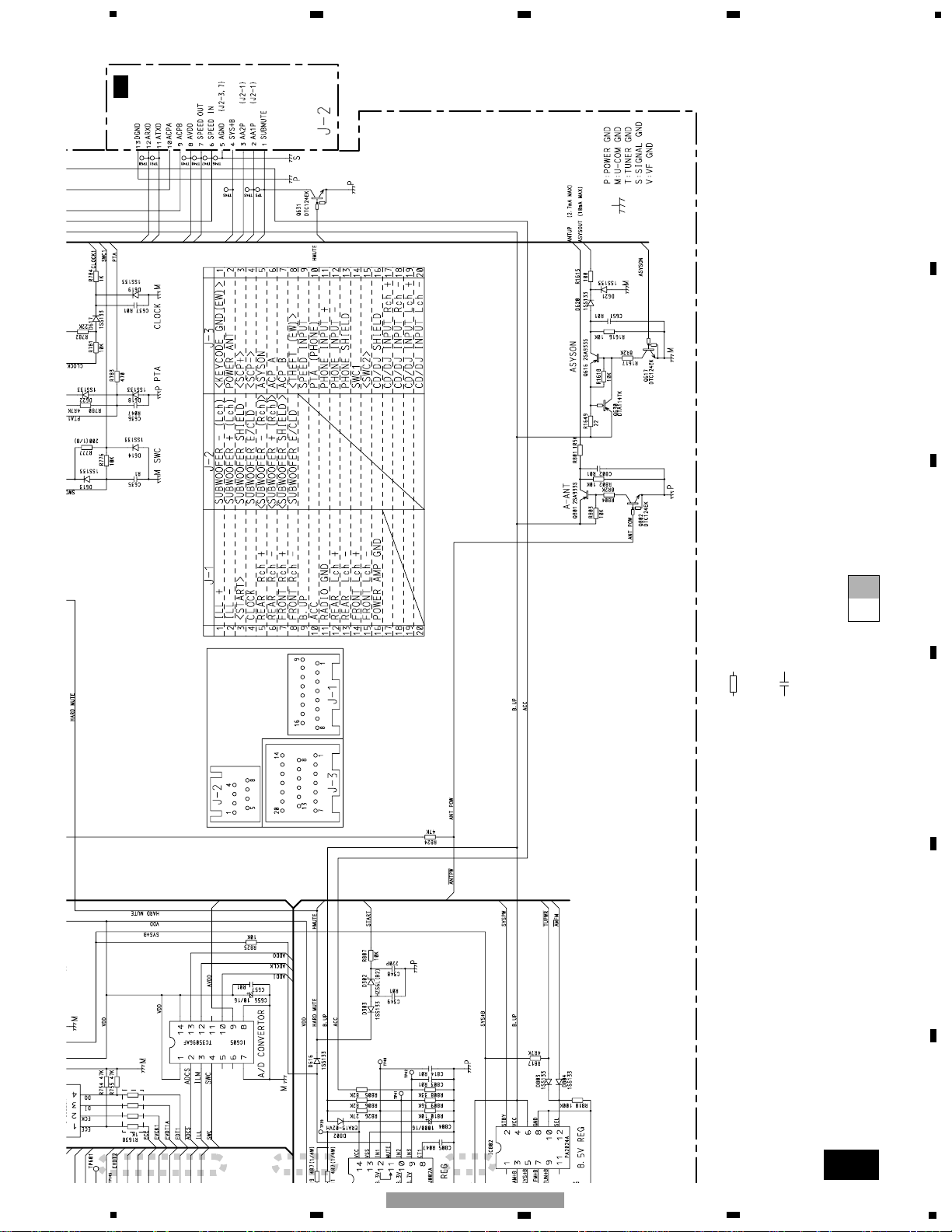
SCHEMATIC DIAGRAM
MOTHER UNIT (GUIDE PAGE)
A-a A-b
A-a
A-b
A-b
A-a
Large size
SCH diagram
Guide page
Detailed page
Note: When ordering service parts, be sure to refer to " EXPLODED VIEWS AND PARTS LIST" or
"ELECTRICAL PARTS LIST".
AF-a
A
F
7.2MHz
I
F
CN251
C
CN957
C
CN958
G
CN701
B
FM/AM TUNER UNIT
TAPE:-11.0dBs
(315Hz 0dB)
CD:-0.4dBs
(1kHz 0dB)
FM:-24.2dBs (30% 1kHz)
AM:-24.4dBs (30% 1kHz)
7
5
6
7
8
F
E
D
C
B
A
5
6
7
8
FH-2327ZF/X1H/UC
AF-b
A
F
Decimal points for resistor
and capacitor fixed values
are expressed as :
2.2 2R2
0.022 R022
←
←
Symbol indicates a resistor.
No differentiation is made between chip resistors and
discrete resistors.
NOTE :
Symbol indicates a capacitor.
No differentiation is made between chip capacitors and
discrete capacitors.
MOTHER UNIT
A
F
E
F
CN1001
D
F
CN201
FM:-16.7dBs
AM:-15.7dBs
CD: +3.3dBs
TAPE: -4.2dBs
PHONE: -4.2dBs
TAPE:+25.8dBs
PHONE:+0.5dBs
600µH
8
1
234
12
34
F
E
D
C
B
A
FH-2327ZF/X1H/UC
A-a
AF-b
AF-a
AF-a
A
F-b
1
2
7.2MHz
B
FM/AM TUNER UNIT
FM:-24.2dBs (30% 1kHz)
AM:-24.4dBs (30% 1kHz)
9
5
6
7
8
F
E
D
C
B
A
5
6
7
8
FH-2327ZF/X1H/UC
A-a
AF-a
AF-b
A
F-a
AF-b
3
4
5
I
F
CN251
C
CN957
C
CN958
G
CN701
TAPE:-11.0dBs
(315Hz 0dB)
CD:-0.4dBs
(1kHz 0dB)
10
1
234
12
34
F
E
D
C
B
A
FH-2327ZF/X1H/UC
AF-b
AF-a
A
F-b
1
2
MOTHER UNIT
A
F
D
F
CN201
600µH
FM:-16.7dBs
AM:-15.7dBs
CD: +3.3dBs
TAPE: -4.2dBs
PHONE: -4.2dBs
TAPE:+25.8dBs
PHONE:+0.5dBs
11
5
6
7
8
F
E
D
C
B
A
5
6
7
8
FH-2327ZF/X1H/UC
AF-b
AF-a
A
F-b
3
4
5
Decimal points for resistor
and capacitor fixed values
are expressed as :
2.2 2R2
0.022 R022
←
←
Symbol indicates a resistor.
No differentiation is made between chip resistors and
discrete resistors.
NOTE :
Symbol indicates a capacitor.
No differentiation is made between chip capacitors and
discrete capacitors.
E
F
CN1001
 Loading...