

Pioneer FH-2077ZF, FH-2177ZF Service Manual

PIONEER CORPORATION 4-1, Meguro 1-Chome, Meguro-ku, Tokyo 153-8654, Japan
PIONEER ELECTRONICS (USA) INC. P.O.Box 1760, Long Beach, CA 90801-1760 U.S.A.
PIONEER EUROPE NV Haven 1087 Keetberglaan 1, 9120 Melsele, Belgium
PIONEER ELECTRONICS ASIACENTRE PTE.LTD. 253 Alexandra Road, #04-01, Singapore 159936
C PIONEER CORPORATION 2002
K-ZZU. JUNE 2002 Printed in Japan
ORDER NO.
CRT2822
RECEIVER ASSY RADIO
FH-207 7
ZF X1H/UC
NOTE:
- Dolby noise reduction manufactured under license from Dolby Laboratories Licensing Corporation.
"Dolby" and the double-D symbol are trademarks of Dolby Laboratories Licensing Corporation.
FORD
VEHICLE PRODUCED AFTER FORD PART No. ID No. PIONEER MODEL No.
FORD RANGER 2002 2L54-18C868-AB − FH-2077ZF/X1H/UC
FORD SPORT TRUCK 2002 2L2T-18C868-AA − FH-2177ZF/X1H/UC
- This service manual should be used together with the following manual(s):
Model No. Order No. Mech. Module Remarks
CX-597 CRT1829 S7
CD Mech. Module:Circuit Description, Mech. Description, Disassembly
CX-1011 CRT2406 3L
Cassette Mech. Module:Mech. Description, Disassembly
For details, refer to "Important symbols for good services".
FH-217 7ZF X1H/UC
FH-2077ZF/X1H/UC

2
FH-2077ZF,2177ZF
[ Important symbols for good services ]
In this manual, the symbols shown-below indicate that adjustments, settings or cleaning should be made securely.
When you find the procedures bearing any of the symbols, be sure to fulfill them:
2. Adjustments
To keep the original performances of the product, optimum adjustments or specification confirmation is indispensable.
In accordance with the procedures or instructions described in this manual, adjustments should be performed.
3. Cleaning
For optical pickups, tape-deck heads, lenses and mirrors used in projection monitors, and other parts requiring cleaning,
proper cleaning should be performed to restore their performances.
5. Lubricants, glues, and replacement parts
Appropriately applying grease or glue can maintain the product performances. But improper lubrication or applying
glue may lead to failures or troubles in the product. By following the instructions in this manual, be sure to apply the
prescribed grease or glue to proper portions by the appropriate amount.For replacement parts or tools, the prescribed
ones should be used.
4. Shipping mode and shipping screws
To protect the product from damages or failures that may be caused during transit, the shipping mode should be set or
the shipping screws should be installed before shipping out in accordance with this manual, if necessary.
1. Product safety
You should conform to the regulations governing the product (safety, radio and noise, and other regulations), and
should keep the safety during servicing by following the safety instructions described in this manual.
CONTENTS
1. SAFETY INFORMATION ...........................................3
2. EXPLODED VIEWS AND PARTS LIST......................4
3. BLOCK DIAGRAM AND SCHEMATIC DIAGRAM..10
4. PCB CONNECTION DIAGRAM ...............................38
5. ELECTRICAL PARTS LIST .......................................54
6. ADJUSTMENT ........................................................66
7. GENERAL INFORMATION ......................................76
7.1 DIAGNOSIS........................................................76
7.1.1 DISASSEMBLY.........................................76
7.1.2 CONNECTOR FUNCTION DESCRIPTION..78
7.1.3 PCB LOCATION ........................................79
7.2 PARTS.................................................................80
7.2.1 IC...............................................................80
7.2.2 DISPLAY ...................................................85
7.3 OPERATION FLOW CHART...............................86
7.4 CLEANING .........................................................87
8. OPERATIONS AND SPECIFICATIONS ...................88

3
FH-2077ZF,2177ZF
This service manual is intended for qualified service technicians; it is not meant for the casual do-it-yourselfer.
Qualified technicians have the necessary test equipment and tools, and have been trained to properly and safely repair
complex products such as those covered by this manual.
Improperly performed repairs can adversely affect the safety and reliability of the product and may void the warranty.
If you are not qualified to perform the repair of this product properly and safely, you should not risk trying to do so
and refer the repair to a qualified service technician.
1. SAFETY INFORMATION

4
FH-2077ZF,2177ZF
A
B
C
F
E
D
2. EXPLODED VIEWS AND PARTS LIST
2.1 EXTERIOR

5
FH-2077ZF,2177ZF
1 Screw BMZ26P250FMC
2 Screw BSZ26P050FMC
3 Screw BSZ30P050FMC
4 Screw BSZ30P120FMC
5
CD Mechanism Module(S7F VA)
CXK5028
6
Cassette Mechanism Module EXK4260
7 Connector CDE5462
8 Case HNB2059
9 Insulator HNM0089
10 Heat Sink HNR1418
11 Rail Guide HNV4897
12 Mother Unit(FH-2077ZF) HWM0072
Mother Unit(FH-2177ZF) HWM0081
13 Plug (CN952) CKS3537
14 Plug (CN953) CKS3538
15 Tuner Unit CWE1428
16 Holder CNC6122
17 Connector (CN901) HKM1237
18 Connector (CN702) CKS3568
19 Connector (CN701) HKS2256
20 Antenna (CN402) HKX1054
21 Holder HNC6458
22 Holder HNC6459
23 Holder HNC6470
* 24 Insulator HNM5228
25
Compound Unit(FH-2077ZF) HWM0074
Compound Unit(FH-2177ZF) HWM0082
26 Screw BMZ26P060FMC
27 Plug (CN1001) CKS1621
28 Plug (CN201) CKS1622
29 Connector(CN1051) HKS3129
* 30 Holder HNC6457
31 Holder HNC6650
32 Shield HNC6930
* 33 Insulator HNM5229
34 Chassis Unit HXA8841
35 Chassis Unit HXA8842
36 Knob Assy CXB8377
37 Grille Unit CXB9218
38 Screw BPZ26P080FMC
39 Screw BSZ30P050FMC
40 Button(EJ) CAC7446
41 Keyboard Unit HWM8124
42 Socket (CN958) CKS3550
43 Socket (CN957) CKS3551
44 VF HAW1359
45 Button(AM) CAC7447
46 Button(FM) CAC7448
47 Connector (CN954) HKS3129
48 Button(MUTE) CAC7449
49 Spacer HNM4761
50 Shield HNC7337
* 51 Insulator HNM5230
52 IC(IC301) TDA7560
53 IC(IC802) PA2024A
54 Transistor (Q618) 2SD2396
55 Transistor (Q803) 2SA1358
56 Transistor (Q805) 2SA1358
57 Transistor (Q1054) 2SD2396
58 Cord HDE5049
59 Tape CNM5582
60 Screw HBA1416
61 Screw HBA1404
62 Sheet CNM5480
63 Rubber HNV4541
* 64 Cord CDE5451
65 Shield CNC9768
66 Cushion CNC9769
67 Button(TAPE) CAC7450
68 Button(CD) CAC7451
69 Button(AUTO,RDS) CAC7452
70 Button(TUNE) CAC7453
71 Button(EJ) CAC7454
72 Button(BASS,TREB) CAC7455
73 Button(BAL,FADE) CAC7456
74 Button(SEL) CAC7457
75 Button(1,2) CAC7458
76 Button(3,4) CAC7459
77 Button(5,6) CAC7460
78 Door CAT2339
* 79 Spring HBH1920
80 Housing CNV7032
- EXTERIOR SECTION PARTS LIST
Mark No. Description Part No.
Mark No. Description Part No.
NOTE:
- Parts marked by “*”are generally unavailable because they are not in our Master Spare Parts List.
- Screws adjacent to ∞ mark on the product are used for disassembly.
- For the applying amount of lubricants or glue, follow the instructions in this manual.
(In the case of no amount instructions, apply as you think it appropriate.)

6
FH-2077ZF,2177ZF
2.2 CD MECHANISM MODULE
G
H
GEM1035
GEM1040

7
FH-2077ZF,2177ZF
1 Control Unit CWX2249
2 Pickup Unit (Service) CXX1232
3 Screw IMS26P035FMC
4 Screw BMZ20P025FMC
5 Screw BMZ20P040FMC
6 Screw BSZ20P040FMC
7 Screw (M2x3) CBA1077
8 Screw (M2x2) CBA1250
9 Screw (M2x5) CBA1399
10 Screw (M2x3.85) CBA1362
11 Spring CBH1724
12 Spring CBH1729
13 Spring CBH1730
14 Spring CBH1731
15 Spring CBH2348
16 Spring CBH1745
17 Spring CBH1848
18 Spring CBH1849
19 Spring CBH1939
20 Spring CBL1497
21 Roller CLA2627
22 Frame CNC8365
23 Bracket CNC5871
* 24 Bracket CNC6376
25 Cushion CNM3917
26 Sheet CNM4873
27 Ball CNR1189
28 P.C.Board CNP5243
29 Bearing CNR1415
30 Belt CNT1071
31 Damper CNV3974
32 Gear CNV5789
33 Gear CNV5820
34 Gear CNV4857
35 Gear CNV5821
36 Holder CNV4663
37 Holder CNV5071
38 Guide CNV5823
39 Screw Unit CXB4265
40 CRG Motor Unit (M2) CXB3043
41 Motor Unit (M1) CXA9101
42 Lever Unit CXA9300
43 Chassis Unit CXB2574
44 Screw JGZ17P025FZK
45 Connector (CN101) CKS1953
46 Connector (CN701) CKS2775
47 Connector (CN801) CKS2196
48 Spring CBH1832
49 Spring CBH1833
50 Roller CLA2627
51 Arm CNV4136
52 Arm Unit CXA8565
53 Bracket CNC6056
54 Load Motor Unit (M3) CXA8702
55 Screw JFZ20P025FMC
56 Arm CNV4120
57 Roller CNV4509
58 Gear Unit CXA8701
59 Screw (M2x5) CBA1399/
60 Frame CNC6844
61 Damper CNV3974
62 Spring CBH1736
63 Spring CBH1863
64 Spring CBH1945
65 Spring CBL1326
66 Arm CNC8364
67 Lever CNC6054
68 Spacer CNM3315
69 Sheet CNM6412
70 Arm CNV5031
71 Arm CNV4123
72 Arm CNV4124
73 Arm CNV4125
74 Arm CNV4138
75 Arm CNV5032
76 Clamper CNV5912
77 Screw (M2x2) CBA1250
78 Connector CDE4576
79 Arm CNC7383
* 80 Gathering P.C.Board CNX2445
81 Photo-transistor (Q1, 2) CPT-230S-X
82 Frame Assy CXB1068
83 Elbo Arm Assy CXA8889
84 Load Motor Assy CXA8891
85 LO Arm Assy CXA8892
86 Shaft CLA3133
87 Guide Arm Assy CXB1850
Mark No. Description Part No. Mark No. Description Part No.
- CD MECHANISM MODULE SECTION PARTS LIST

8
FH-2077ZF,2177ZF
2.3 CASSETTE MECHANISM MODULE
For grease application, refer to the service manual for CX-1011 (CRT2406).
I
J

9
FH-2077ZF,2177ZF
Mark No. Description Part No. Mark No. Description Part No.
- CASSETTE MECHANISM MODULE PARTS LIST
1 Screw BSZ20P040FMC
2 Washer CBF1037
3 Washer CBG1003
4 Screw EBA1028
5 Screw CBA1037
6 Spring EBH1653
7 Spring EBH1642
8 Spring EBH1641
9 Spring EBH1626
10 Spring EBH1627
11 Spring EBH1648
12 Cord EDD1024
13 Photo-reflector(Q101) EGN1004
14 Arm ENC1526
* 15 Lever ENC1544
16 Lever ENC1543
17 Arm ENC1532
18 Frame ENC1533
19 Holder ENC1547
20 Gear ENC1535
21 Arm ENC1550
22 Roller ENR1040
23 Belt ENT1027
24 Collar ENV1508
25 Arm ENV1539
26 Arm ENV1540
27 Gear ENV1569
28 Gear ENV1547
29 Gear ENR1044
30 Worm Wheel ENV1559
31 Lever ENV1551
32 Flywheel ENV1554
33 PCB ENP1196
34 Switch(S101,S102,S103) ESG1007
35 Deck Unit EWM1031
36 Plug(CN251) CKS3540
37 Gathering PCB ENX1066
38 Motor Unit(M1) EXA1491
39 Motor EXM1028
40 Head Assy(HD1) EXA1594
41 Arm ENC1537
42 Screw JGZ20P025FNI
43 Guide ENC1545
44 Chassis Unit EXA1609
45 Pinch Holder Unit EXA1608
46 Pinch Roller ENV1518
47 Pinch Holder Unit EXA1607
48 Pinch Roller ENV1518
49 Reel Unit EXA1625
50 Head Base Unit EXA1611
51 Lever Unit EXA1587
52 Gear Unit EXA1596
53 Motor Unit(M2) EXA1623
54 Washer HBF-179
55 Spring EBH1537
56 Worm Gear ENV1564
57 Spring EBH1654
58 •••••
59 •••••
60 Tube ENM1039
61 •••••
62 Spring EBH1545
63 Sensor Unit EWM1036

10
FH-2077ZF,2177ZF
A
1
234
B
C
D
12
34
A
B
G
I
J
H
SENSOR UNIT
346
346
3
40
39
37
16
HA12216F
LC72146MQ2
PE5315A
PM4006B
PD6181B
IC604
TC7S86F
5
1,2 4
64
3. BLOCK DIAGRAM AND SCHEMATIC DIAGRAM
3.1 BLOCK DIAGRAM

11
FH-2077ZF,2177ZF
5
6
7
8
A
B
C
D
5
6
7
8
C
F
D
E
BA4558F-P
SC33165ADWR2
KEYBOARD UNIT
1
3
7
6
79,80
ROTIN
ROTINT
67
PE5188A
TDA7560
7.5V
5
5
AMP Enable
SUB+
Pre-out L
AMP Enable
12
FH-2077ZF,2177ZF
A
1
234
B
C
D
12
34
3.2 OVERALL CONNECTION DIAGRAM(GUIDE PAGE)
Note: When ordering service parts, be sure to refer to “EXPLODED VIEWS AND PARTS LIST” or “ELECTRICAL PARTS
LIST”.
A-a A-b
A-a
A-b
A-b
A-a
Large size
SCH diagram
Guide page
Detailed page
B
G
CN701
I
CN251
C
CN957
C
CN958
FMUTE
PLL
RDS
MICRO
COMPUTER
RBDS
SUB MICRO
COMPUTER
MAIN
MICRO COMPUTER
-8.4dBs
CD 1kHz 0dB
-8.24dBs
FM(30% 1kHz)
-24.2dBs
AM(30% 1kHz)
-24.4dBs
-16.4
A-a
A

13
FH-2077ZF,2177ZF
5
6
7
8
A
B
C
D
5
6
7
8
0R0
0R0
R068(FH-2077ZF)
R056(FH-2177ZF)
R039(FH-2077ZF)
R027(FH-2177ZF)
CTH1171 600mH
E
CN1001
CN801
D
CN201
5R1K(FH-2077ZF)
1R8K(FH-2177ZF)
Decimal points for resistor
and capacitor fixed values
are expressed as :
2.2 2R2
0.022 R022
←
←
Symbol indicates a resistor.
No differentiation is made between chip resistors and
discrete resistors.
NOTE :
Symbol indicates a capacitor.
No differentiation is made between chip capacitors and
discrete capacitors.
A
MOTHER UNIT
E-VOL
E-VOL
POWER AMP
0.5dBs
9.5dBs
(1kHz 0dB)
-16.4dBs
-12.0dBs
-1.9dBs
-1.9dBs
CD : 3.3dBs
DJPL : -4.2dBS
TAPE : -4.2dBs
FM : -16.7dBs
AM : -15.7dBs
TAPE: :25.0dBs
A
A-b

14
FH-2077ZF,2177ZF
A
1
234
B
C
D
12
34
B
PLL
RDS
MICRO
COMPUTER
FM(30% 1kHz)
-24.2dBs
AM(30% 1kHz)
-24.4dBs
-16.4dBs
-12
-1
-1
A-a
A-a
A-b
1
2
3

15
FH-2077ZF,2177ZF
5
6
7
8
A
B
C
D
5
6
7
8
G
CN701
I
CN251
C
CN957
C
CN958
FMUTE
RDS
MICRO
COMPUTER
RBDS
SUB MICRO
COMPUTER
MAIN
MICRO COMPUTER
-8.4dBs
CD 1kHz 0dB
-8.24dBs
A-a
A-a
A-b
4

16
FH-2077ZF,2177ZF
A
1
234
B
C
D
12
34
CTH1171 600mH
D
CN201
A
MOTHER UNIT
E-VOL
E-VOL
POWER AMP
0.5dBs
9.5dBs
(1kHz 0dB)
-16.4dBs
-12.0dBs
-1.9dBs
-1.9dBs
CD : 3.3dBs
DJPL : -4.2dBS
TAPE : -4.2dBs
FM : -16.7dBs
AM : -15.7dBs
TAPE: :25.0dBs
A-a
A-b
A-b
1
2
3

17
FH-2077ZF,2177ZF
5
6
7
8
A
B
C
D
5
6
7
8
0R0
0R0
R068(FH-2077ZF)
R056(FH-2177ZF)
R039(FH-2077ZF)
R027(FH-2177ZF)
E
CN1001
CN801
5R1K(FH-2077ZF)
1R8K(FH-2177ZF)
Decimal points for resistor
and capacitor fixed values
are expressed as :
2.2 2R2
0.022 R022
←
←
Symbol indicates a resistor.
No differentiation is made between chip resistors and
discrete resistors.
NOTE :
Symbol indicates a capacitor.
No differentiation is made between chip capacitors and
discrete capacitors.
A-b
A-a
A-b
4

18
FH-2077ZF,2177ZF
A
1
234
B
C
D
12
34
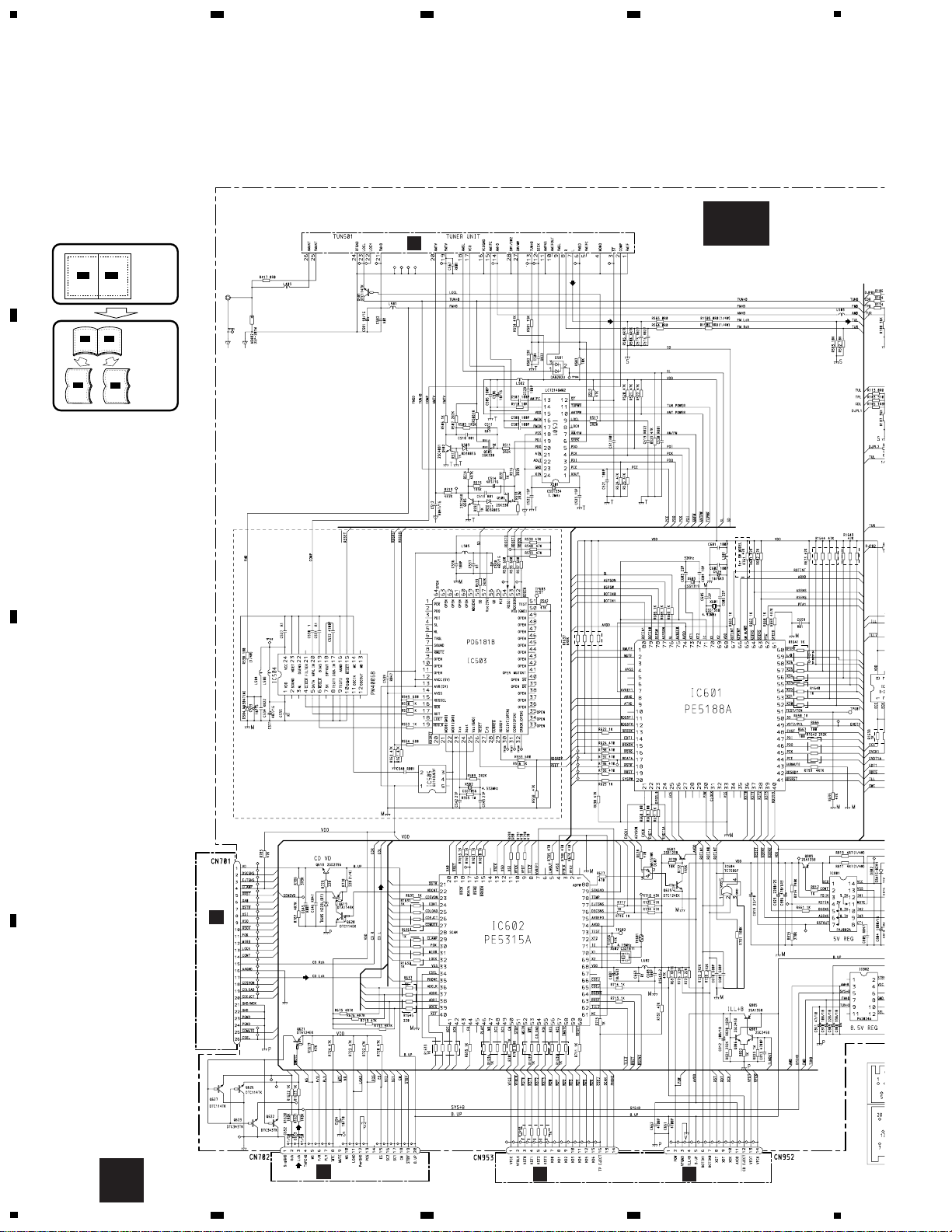
3.3 TUNER UNIT
A
B
B

19
FH-2077ZF,2177ZF
5
6
7
8
A
B
C
D
5
6
7
8
B

20
FH-2077ZF,2177ZF
A
1
234
B
C
D
12
34
A
CN953
Key Matric Circuit
Button Illumination
Switch Circuit
UDZS3R9(B)
C
KEYBOARD UNIT
F
CN1051
3.4 KEYBOARD UNIT
C

21
FH-2077ZF,2177ZF
5
6
7
8
A
B
C
D
5
6
7
8
VF Driver IC
-8.0V Regulator
Voltage Baffer for VF Gfid
VF HAW 1359
A
CN952
C

22
FH-2077ZF,2177ZF
A
1
234
B
C
D
12
34
FH-2177ZF model only
R1290
R1289
FH
C267,C268
C269,C270
R287,R288
R1289,R1290
R1278 R1277
C209
R01
C210
R01
8R2K
8R2K
R18
R18
R068
R068
D
EQ PCB
A
CN301
COMPOUND UNIT
Consists of
EQ PCB
CONNECTOR PCB
VF SUB PCB
FH-2077ZF
5600P
R001
R018
R01
2R7K
-
-
8R2K
C213,C214
C215,C216
C217,C218
C1223,C1224
R215,R216
R225,R226
R1275,R1276
R1277,R1278
FH-2177ZF
R047
R082
R001
5600P
-
6R8K
220
-
1R2K
1R2K
1R2K
1R2K
68K
68K
68K
68K
3.5 EQ PCB
D

23
FH-2077ZF,2177ZF
5
6
7
8
A
B
C
D
5
6
7
8
FH-2077ZF
R01
R018
-
0R0
FH-2177ZF
R022
R027
2R7K
-
3R9K
3R9K
R33
R33
R33
R33
6R8K
6R8K
3R9K
3R9K
2R2K
2R2K
R33
R33
R33
R33
0R0
R302
0R0
R301
0R0
R257
0R0
R257
Fix EQ Circuit
Auot level
Control Circuit
Analog Switch
for Dual Play
Auto level
Control Circuit
D

24
FH-2077ZF,2177ZF
A
1
234
B
C
D
12
34
E
VF SUB PCB
A
CN801
COMPOUND UNIT
Consists of
EQ PCB
CONNECTOR PCB
VF SUB PCB
ACP Bus Transceiver Receiver
7.5V Output for Subwoofer Amplifer
SUB MUTE
3.6 CONNECTOR PCB
E

25
FH-2077ZF,2177ZF
1
2
3
4
A
B
C
D
1
2
3
4
F
VF SUB PCB
C
CN954
COMPOUND UNIT
Consists of
EQ PCB
CONNECTOR PCB
VF SUB PCB
6.2V Regulator
27kHz Oscilator
for VF Filament
DC/DC Convertor(-39V)
3.7 VF SUB PCB
F

26
FH-2077ZF,2177ZF
A
1
234
B
C
D
12
34
G
H
CL203IRXTU CL203IRXTU
BA6997FP
3.8 CD MECHANISM MODULE
G-a
G
H

27
FH-2077ZF,2177ZF
5
6
7
8
A
B
C
D
5
6
7
8
A
CSS1504
G-b
G
 Loading...