

PIONEER FH-2006 Service Manual

PIONEER CORPORATION 4-1, Meguro 1-Chome, Meguro-ku, Tokyo 153-8654, Japan
PIONEER ELECTRONICS SERVICE INC. P.O.Box 1760, Long Beach, CA 90801-1760 U.S.A.
PIONEER EUROPE NV Haven 1087 Keetberglaan 1, 9120 Melsele, Belgium
PIONEER ELECTRONICS ASIACENTRE PTE.LTD. 253 Alexandra Road, #04-01, Singapore 159936
C PIONEER CORPORATION 2001
K-ZZB. MAY 2001 Printed in Japan
ORDER NO.
CRT2697
RECEIVER ASSY RADIO
FH-2006ZF-03 X1H/UC
FORD
VEHICLE DESTINATION PRODUCED AFTER PART No. ID No. PIONEER MODEL No.
ESCAPE U.S.A., CANADA May 2001 YL8F-18C868-BB FH-2006ZF-03/X1H/UC
- This service manual should be used together with the manual(s) listed below.
For the parts numbers, adjustments, etc. which are not shown in this manual,
refer to the following manual(s).
Model Order No. Mech. Module Remarks
CX-597 CRT1829 S7 CD Mech. Module:Circuit Description, Mech.Description, Disassembly
CX-1011 CRT2406 3L Cassette Mech. Module:Mech.Description, Disassembly, Adjustment
FH-2006ZF/X1H/UC CRT2481
FH-2076ZF/X1H/UC CRT2025

2
FH-2006ZF-03
EXPLODED VIEWS AND PARTS LIST
EXTERIOR (Page 3)
- EXTERIOR SECTION PARTS LIST
Part No.
Mark No. Description FH-2006ZF/X1H/UC FH-2006ZF-03/X1H/UC
6 Cassette Mechanism Module EXK3285 EXK4260
9 Insulator HNM4745 HNM0089
12 Mother Unit HWM7067 HWM0064
18 Connector(CN702) HKS1730 CKS3568
25 Compound Unit HWM7068 HWM0065
3
FH-2006ZF-03
ELECTRICAL PARTS LIST(Page 52)
Mother Unit
Part No.
Symbol and Description FH-2006ZF/X1H/UC FH-2006ZF-03/X1H/UC
IC602 IC PE5189A PE5250A
D501 Diode 1SS133 DAN202U
D502 Diode 1SS133 Not used
R502 RS1/10S223J RS1/16S223J
R506 RS1/10S102J RS1/16S102J
R507 RS1/10S222J RS1/16S222J
R523 RS1/10S473J RS1/16S473J
R721 RS1/10S473J Not used
C293 CKSYB274K16 CKSQYB274K16
C295 CKSYB103K25 CKSRYB103K50
C504 CKSQYB223K50 CKSRYB223K50
C520 CKSQYB102K50 CKSRYB102K50
C530 CKSYB105K16 CKSQYB105K16
C567 CKSYB102K50 CCSRCH102J50
C1203 CKSYB563K25 CKSRYB563K16
C1205 CKSYB123K50 CKSRYB123K50
Compound Unit
Part No.
Symbol and Description FH-2006ZF/X1H/UC FH-2006ZF-03/X1H/UC
C207,208 CKSYB273K50 CKSRYB273K50
C213,214 CKSYB681K50 CKSQYB681K50
C215,216 CKSYB103K25 CKSRYB103K50
C217,218,255,256 CKSYB221K50 CKSRYB221K50
C223,224 CKSYB683K25 CKSRYB683K16
C227,230 CKLSR104K16 CKSYB104K16
C228,229,231,232,273,274,275,276,277,278 CKLSR104K16 CKSRYB104K25
C253,254 CKSYB222K50 CKSRYB222K50
C261,262 CKSYB821K50 CKSRYB821K50
1
23
4
56
9
10 11
12
13 14
7
818
15
16
17
19
20 21
24
25 26
27
28 29
34
35 36
31
32 33
22
23
30
G
CN701
4
FH-2006ZF-03
A
1
234
B
C
D
12
34
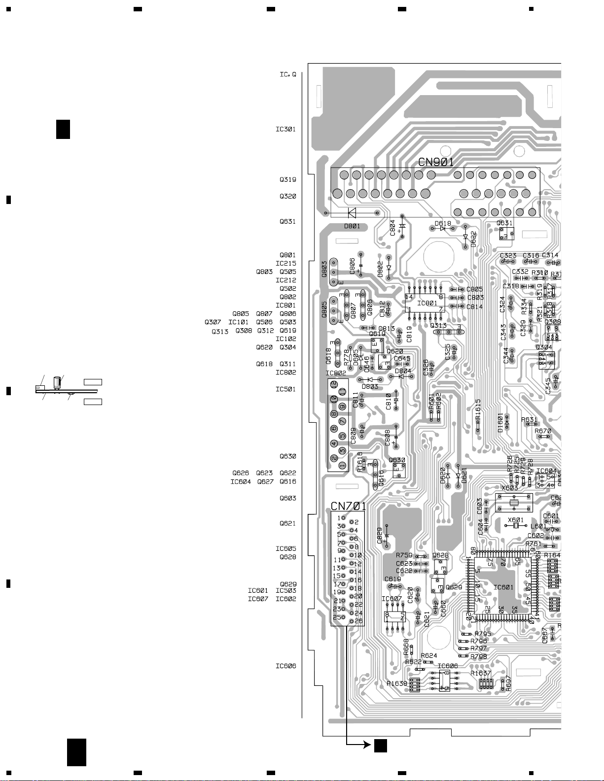
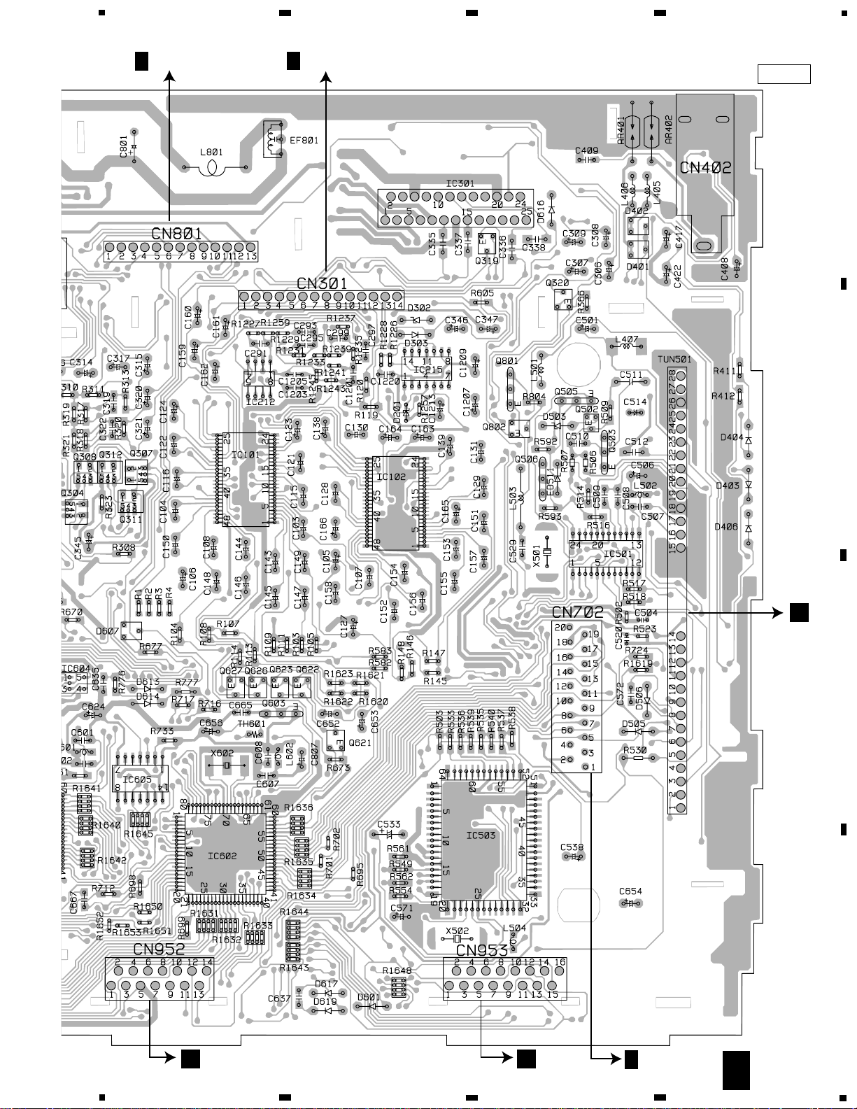
PCB CONNECTION DIAGRAM
MOTHER UNIT (Page 36)
NOTE FOR PCB DIAGRAMS
1. The parts mounted on this PCB
include all necessary parts for
several destination.
For further information for
respective destinations, be sure
to check with the schematic diagram.
2. Viewpoint of PCB diagrams
Capacitor
Connector
P.C.Board
Chip Part
SIDE A
SIDE B
MOTHER UNIT
A
F
A
F
5
FH-2006ZF-03
5
6
7
8
A
B
C
D
5
6
7
SIDE A
A
F
8
E
CN1001
F
D
CN201
F
ANTENNA
B
C
CN958
FRONT
CN957
C
I
CN251
F

6
FH-2006ZF-03
A
1
234
B
C
D
12
34
MOTHER UNIT
A
F
A
F
 Loading...