

Pioneer DV-300, DV-300-K Service manual
PIONEER CORPORATION 4-1, Meguro 1-chome, Meguro-ku, Tokyo 153-8654, Japan
PIONEER ELECTRONICS (USA) INC. P.O. Box 1760, Long Beach, CA 90801-1760, U.S.A.
PIONEER EUROPE NV Haven 1087, Keetberglaan 1, 9120 Melsele, Belgium
PIONEER ELECTRONICS ASIACENTRE PTE. LTD. 253 Alexandra Road, #04-01, Singapore 159936
PIONEER CORPORATION 2007
MENU
STANDBY/
ON
DV-300-K
TOP MENU
ENTER
HOME
MENU
OPEN/CLOSE
RETURN
DVD PLAYER
DV-300-K
THIS MANUAL IS APPLICABLE TO THE FOLLOWING MODEL(S) AND TYPE(S).
Model Type Power Requirement Region No. Remarks
DV-300-K KUCXZT AC 120 V 1
ORDER NO.
RRV3584
For details, refer to "Important Check Points for Good Servicing" .
T-ZZV APR. 2007 printed in Japan
1234
SAFETY INFORMATION
A
This service manual is intended for qualified service technicians; it is not meant for the casual
do-it-yourselfer. Qualified technicians have the necessary test equipment and tools, and have been
trained to properly and safely repair complex products such as those covered by this manual.
Improperly performed repairs can adversely affect the safety and reliability of the product and may
void the warranty. If you are not qualified to perform the repair of this product properly and safely, you
should not risk trying to do so and refer the repair to a qualified service technician.
WARNING
This product contains lead in solder and certain electrical parts contain chemicals which are known to the state of California to
B
cause cancer, birth defects or other reproductive harm.
Health & Safety Code Section 25249.6 – Proposition 65
NOTICE
(FOR CANADIAN MODEL ONLY)
Fuse symbols (fast operating fuse) and/or (slow operating fuse) on PCB indicate that replacement
parts must be of identical designation.
REMARQUE
(POUR MODÈLE CANADIEN SEULEMENT)
Les symboles de fusible (fusible de type rapide) et/ou (fusible de type lent) sur CCI indiquent que
C
les pièces de remplacement doivent avoir la même désignation.
(FOR USA MODEL ONLY)
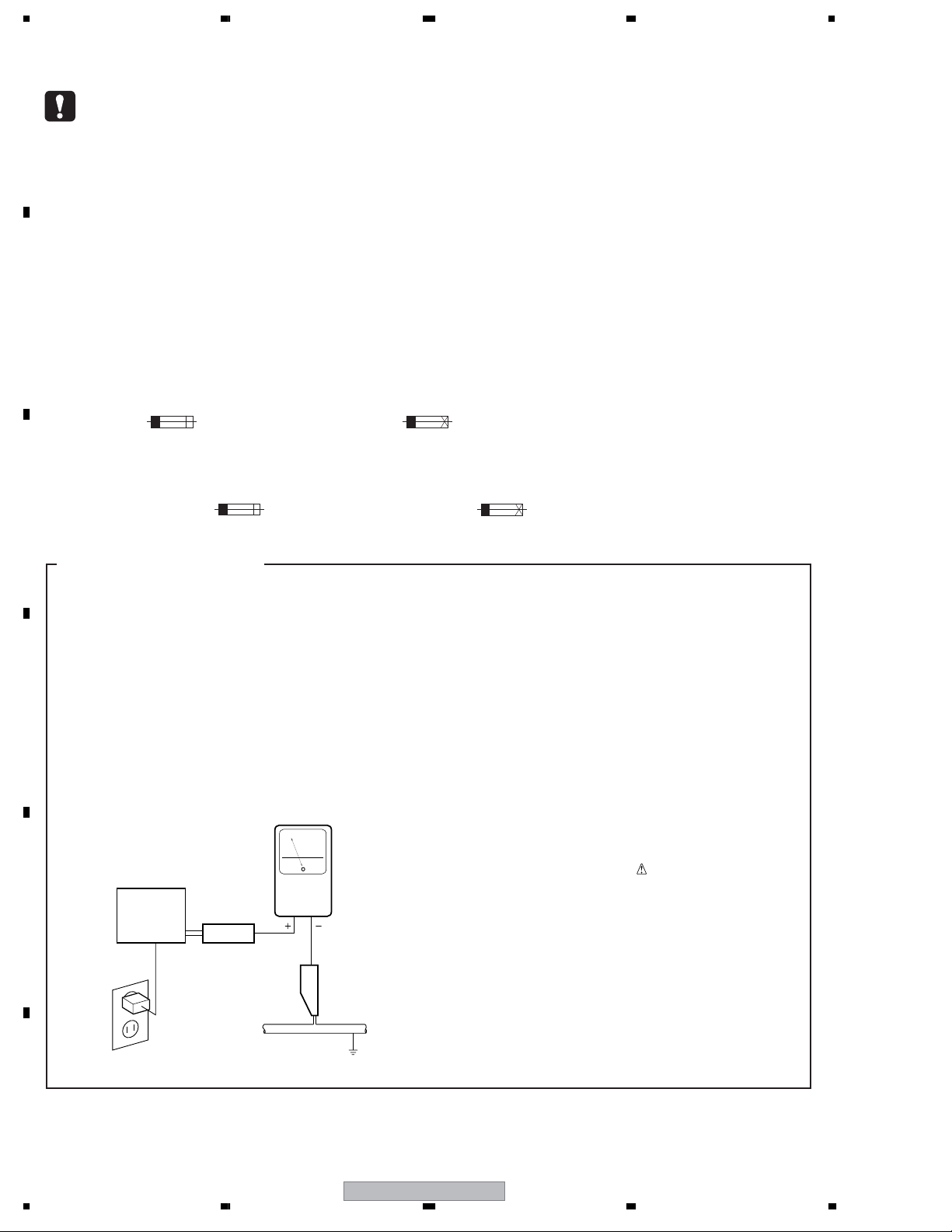
1. SAFETY PRECAUTIONS
The following check should be performed for the
continued protection of the customer and service
technician.
LEAKAGE CURRENT CHECK
Measure leakage current to a known earth ground
(water pipe, conduit, etc.) by connecting a leakage
current tester such as Simpson Model 229-2 or
D
equivalent between the earth ground and all exposed
metal parts of the appliance (input/output terminals,
screwheads, metal overlays, control shaft, etc.). Plug
the AC line cord of the appliance directly into a 120V
AC 60 Hz outlet and turn the AC power switch on. Any
current measured must not exceed 0.5 mA.
Leakage
current
E
Device
under
test
Also test with
plug reversed
(Using AC adapter
plug as required)
Test all
exposed metal
surfaces
AC Leakage Test
tester
Reading should
not be above
0.5 mA
Earth
ground
ANY MEASUREMENTS NOT WITHIN THE
LIMITS OUTLINED ABOVE ARE INDICATIVE
OF A POTENTIAL SHOCK HAZARD AND
MUST BE CORRECTED BEFORE RETURNING THE APPLIANCE TO THE CUSTOMER.
2. PRODUCT SAFETY NOTICE
Many electrical and mechanical parts in the appliance
have special safety related characteristics. These are
often not evident from visual inspection nor the
protection afforded by them necessarily can be obtained
by using replacement components rated for voltage,
wattage, etc. Replacement parts which have these
special safety characteristics are identified in this
Service Manual.
Electrical components having such features are
identified by marking with a
on the parts list in this Service Manual.
The use of a substitute replacement component which
does not have the same safety characteristics as the
PIONEER recommended replacement one, shown in the
parts list in this Service Manual, may create shock, fire,
or other hazards.
Product Safety is continuously under review and new
instructions are issued from time to time. For the latest
information, always consult the current PIONEER
Service Manual. A subscription to, or additional copies
of, PIONEER Service Manual may be obtained at a
nominal charge from PIONEER.
on the schematics and
F
2
1234
DV-300-K

5678
WARNING !
THE AEL (ACCESSIBLE EMISSION LEVEL) OF THE LASER POWER OUTPUT IS LESS THAN CLASS 1
BUT THE LASER COMPONENT IS CAPABLE OF EMITTING RADIATION EXCEEDING THE LIMIT FOR
CLASS 1.
A SPECIALLY INSTRUCTED PERSON SHOULD DO SERVICING OPERATION OF THE APPARATUS.
LASER DIODE CHARACTERISTICS
FOR DVD : MAXIMUM OUTPUT POWER : 5 mW
WAVELENGTH : 650 nm
FOR CD : MAXIMUM OUTPUT POWER : 5 mW
WAVELENGTH : 780 nm
A
LABEL CHECK
Location: inside of the unit
(Printed on the Rear Panel)
Additional Laser Caution
1.
• Laser diode is driving with Q2303,Q2305(650nm LD) and Q2302,
Q2304(780nm LD)on the DVD MT PCB Assy.
Therefore, when short-circuit between the emitter and collector of these
transistors or the base voltage is supplied for transistors turn on, the
laser oscillates. (failure mode)
• In the test mode ∗ , there is the mode that the laser oscillates except
for the disc judgment and playback. LD ON mode in the test mode
oscillates with the laser forcibly.
2. When the cover is open, close viewing through the objective lens with
the naked eye will cause exposure to the laser beam.
B
C
D
S
T
A
N
O
D
N
B
Y
/
OPEN
/C
LOS
E
T
O
P
M
E
N
U
M
H
E
O
N
M
U
E
M
E
N
U
E
N
T
E
R
R
E
T
U
R
N
∗ : See page 28.
E
F
56
DV-300-K
7
8
3
1234
[Important Check Points for Good Servicing]
In this manual, procedures that must be performed during repairs are marked with the below symbol.
Please be sure to confirm and follow these procedures.
A
1. Product safety
Please conform to product regulations (such as safety and radiation regulations), and maintain a safe servicing environment by
following the safety instructions described in this manual.
1 Use specified parts for repair.
Use genuine parts. Be sure to use important parts for safety.
2 Do not perform modifications without proper instructions.
Please follow the specified safety methods when modification(addition/change of parts) is required due to interferences such as
radio/TV interference and foreign noise.
B
C
D
3 Make sure the soldering of repaired locations is properly performed.
When you solder while repairing, please be sure that there are no cold solder and other debris.
Soldering should be finished with the proper quantity. (Refer to the example)
4 Make sure the screws are tightly fastened.
Please be sure that all screws are fastened, and that there are no loose screws.
5 Make sure each connectors are correctly inserted.
Please be sure that all connectors are inserted, and that there are no imperfect insertion.
6 Make sure the wiring cables are set to their original state.
Please replace the wiring and cables to the original state after repairs.
In addition, be sure that there are no pinched wires, etc.
7 Make sure screws and soldering scraps do not remain inside the product.
Please check that neither solder debris nor screws remain inside the product.
8 There should be no semi-broken wires, scratches, melting, etc. on the coating of the power cord.
Damaged power cords may lead to fire accidents, so please be sure that there are no damages.
If you find a damaged power cord, please exchange it with a suitable one.
9 There should be no spark traces or similar marks on the power plug.
When spark traces or similar marks are found on the power supply plug, please check the connection and advise on secure
connections and suitable usage. Please exchange the power cord if necessary.
0 Safe environment should be secured during servicing.
When you perform repairs, please pay attention to static electricity, furniture, household articles, etc. in order to prevent injuries.
Please pay attention to your surroundings and repair safely.
2. Adjustments
To keep the original performance of the products, optimum adjustments and confirmation of characteristics within specification.
Adjustments should be performed in accordance with the procedures/instructions described in this manual.
3. Lubricants, Glues, and Replacement parts
Use grease and adhesives that are equal to the specified substance.
E
Make sure the proper amount is applied.
4. Cleaning
For parts that require cleaning, such as optical pickups, tape deck heads, lenses and mirrors used in projection monitors, proper
cleaning should be performed to restore their performances.
5. Shipping mode and Shipping screws
To protect products from damages or failures during transit, the shipping mode should be set or the shipping screws should be
installed before shipment. Please be sure to follow this method especially if it is specified in this manual.
F
4
1234
DV-300-K

5678
CONTENTS
SAFETY INFORMATION......................................................................................................................................2
1. SERVICE PRECAUTIONS ................................................................................................................................6
1.1 NOTES ON SOLDERING...........................................................................................................................6
1.2 WHEN REPLACING DVD DECK................................................................................................................6
1.3 DISC REMOVAL METHOD ........................................................................................................................7
2. SPECIFICATIONS.............................................................................................................................................8
2.1 ACCESSORIES..........................................................................................................................................8
2.2 SPECIFICATIONS ......................................................................................................................................9
2.3 DISC/CONTENT FORMAT .......................................................................................................................10
2.4 PANEL FACILITIES...................................................................................................................................12
3. BASIC ITEMS FOR SERVICE ........................................................................................................................15
3.1 CHECK POINTS AFTER SERVICING .....................................................................................................15
3.2 PCB LOCATIONS .....................................................................................................................................16
3.3 JIGS LIST .................................................................................................................................................17
4. BLOCK DIAGRAM ..........................................................................................................................................18
4.1 OVERALL WIRING CONNECTION DIAGRAM ........................................................................................18
4.2 OVERALL BLOCK DIAGRAM ..................................................................................................................20
4.3 DVD LOADER BLOCK DIAGRAM............................................................................................................21
4.4 POWER BLOCK DIAGRAM .....................................................................................................................22
5. DIAGNOSIS ....................................................................................................................................................23
5.1 TROUBLE SHOOTING.............................................................................................................................23
5.2 METHOD FOR DIAGNOSING DEGRADATION OF THE LDS ON THE PICKUP ASSY .........................27
6. SERVICE MODE .............................................................................................................................................28
6.1 SERVICE MODE PROCEDURE ..............................................................................................................28
6.2 SERVICE MODE IN..................................................................................................................................29
6.3 DISPLAY SPECIFICATION OF THE SERVICE MODE ............................................................................30
6.4 FUNCTIONAL SPECIFICATION OF THE SHORTCUT KEY ...................................................................31
6.5 FUNCTIONAL SPECIFICATION OF THE SERVICE MODE....................................................................32
7. DISASSEMBLY ...............................................................................................................................................33
7.1 EXTERIOR SECTION ..............................................................................................................................33
7.2 DVD DECK SECTION ..............................................................................................................................34
8. EACH SETTING AND ADJUSTMENT ............................................................................................................38
8.1 ADJUSTMENT..........................................................................................................................................38
8.2 RE-WRITE FOR DVD FIRMWARE...........................................................................................................38
9. EXPLODED VIEWS AND PARTS LIST ...........................................................................................................40
9.1 PACKING SECTION .................................................................................................................................40
9.2 EXTERIOR SECTION ..............................................................................................................................42
9.3 06 DVD MECHA SECTION ......................................................................................................................44
10. SCHEMATIC DIAGRAM................................................................................................................................46
10.1 DVD MT PCB ASSY (1/6).......................................................................................................................46
10.2 DVD MT PCB ASSY(2/6)........................................................................................................................48
10.3 DVD MT PCB ASSY(3/6)........................................................................................................................50
10.4 DVD MT PCB ASSY(4/6)........................................................................................................................52
10.5 DVD MT PCB ASSY(5/6)........................................................................................................................54
10.6 DVD MT PCB ASSY(6/6)........................................................................................................................56
10.7 OPERATION 1 and OPERATION 2 PCB ASSYS...................................................................................58
10.8 POWER PCB ASSY ...............................................................................................................................60
10.9 WAVE FORMS........................................................................................................................................62
11. PCB CONNECTION DIAGRAM ....................................................................................................................63
11.1 LOADING MOTOR/SW...........................................................................................................................64
11.2 DVD MT PCB ASSY...............................................................................................................................64
11.3 OPERATION 1 PCB and OPERATION 2 PCB ASSYS ..........................................................................66
11.4 POWER PCB ASSY ...............................................................................................................................67
12. PCB PARTS LIST..........................................................................................................................................69
A
B
C
D
E
56
DV-300-K
F
5
7
8
1234
1. SERVICE PRECAUTIONS
1.1 NOTES ON SOLDERING
NOTES ON SOLDERING
A
• For environmental protection, lead-free solder is used on the printed circuit boards mounted in this unit.
Be sure to use lead-free solder and a soldering iron that can meet specifications for use with lead-free solders for repairs
accompanied by reworking of soldering.
• Compared with conventional eutectic solders, lead-free solders have higher melting points, by approximately 40 ºC.
Therefore, for lead-free soldering, the tip temperature of a soldering iron must be set to around 373 ºC in general, although
the temperature depends on the heat capacity of the PC board on which reworking is required and the weight of the tip of
the soldering iron.
Do NOT use a soldering iron whose tip temperature cannot be controlled.
B
Compared with eutectic solders, lead-free solders have higher bond strengths but slower wetting times and higher melting
temperatures (hard to melt/easy to harden).
The following lead-free solders are available as service parts:
• Parts numbers of lead-free solder:
GYP1006 1.0 in dia.
GYP1007 0.6 in dia.
GYP1008 0.3 in dia.
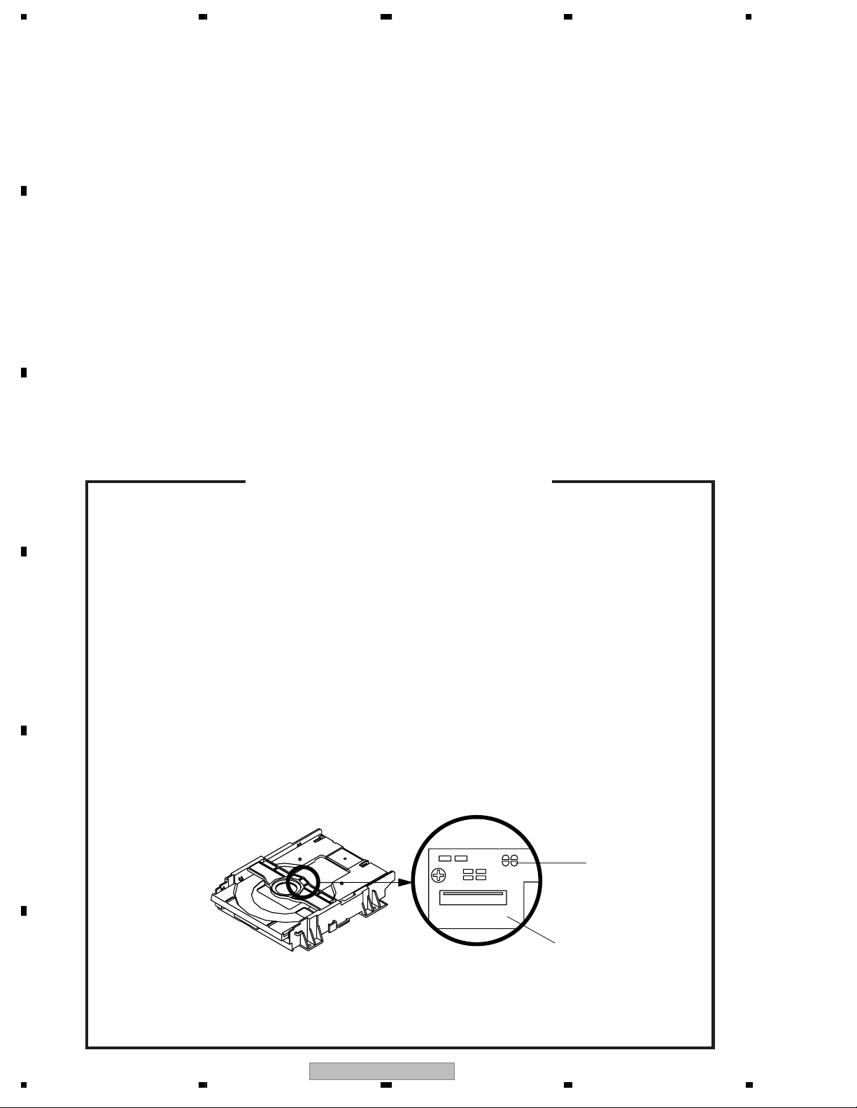
1.2 WHEN REPLACING DVD DECK
C
WHEN REPLACING DVD DECK
[ Removing the DVD Deck ]
Before removing Pick Up PCB and DVD PCB connector, short circuit the position shown in Fig. 1 using
a soldering iron. If you remove the DVD Deck with no soldering, the Laser may be damaged.
[ Installing the DVD Deck ]
Remove all the soldering on the short circuit position after the connection of Pick Up PCB and DVD
D
E
PCB connector.
NOTE
•
Before your operation, please read “PREPARATION OF SERVICING” .
•
Use the Lead Free solder.
•
Manual soldering conditions
• Soldering temperature: 320 ± 20˚C
• Soldering time: Within 3 seconds
• Soldering combination: Sn-3.0Ag-0.5Cu
•
When Soldering/Removing of solder, use the draw in equipment over the Pick Up Unit to prevent the
Flux smoke from it.
Short circuit using a
soldering iron.
Pick Up PCB
F
Fig. 1
6
1234
DV-300-K
5678
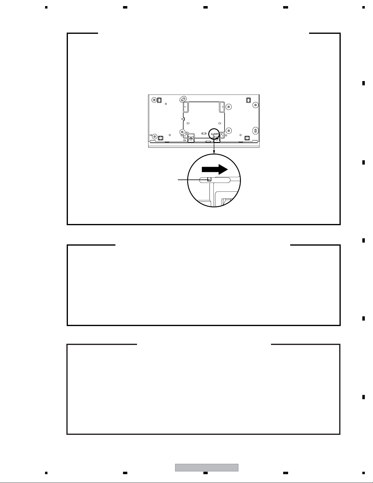
1.3 DISC REMOVAL METHOD
DISC REMOVAL METHOD AT NO POWER SUPPLY
Slide the Rack Loading (White) toward the arrow direction by using a minus driver to release the lock.
1.
(Refer to Fig. 1)
Manually open the Tray.
2.
NOTE:
Please strongly pushing Rack Loading (White) to release the lock because the tray doesn't go out
easily.
A
DVD Player (Bottom Side)
B
Rack Loading (White)
Fig. 1
PARENTAL CONTROL - RATING LEVEL
4 DIGIT PASSWORD CANCELLATION
If the stored 4 digit password in the Rating Level menu needs to be cancelled, please follow the steps
below.
Set the DVD to the Stand-by Mode.
1.
Press and hold the 'STOP' key on the front panel.
2.
3.
Simultaneously press and hold the POWER key on the front panel.
The 4 digit password has now been cleared.
4.
NOTE: The above procedure will reset ALL of the player's settings to the default factory state.
PREPARATION OF SERVICING
C
D
The laser diode used for a pickup head may be destroyed with external static electricity.
Moreover, even if it is operating normally after repair, when static electricity discharge is
received at the time of repair, the life of the product may be shortened.
Please perform the following measure against static electricity, be careful of destruction of a
laser diode at the time of repair.
• Place the unit on a workstation equipped to protect against static electricity, such as
conductive mat.
• Soldering iron with ground wire or ceramic type is used.
• A worker needs to use a ground conductive wrist strap for body.
56
DV-300-K
7
E
F
7
8
1234
2. SPECIFICATIONS
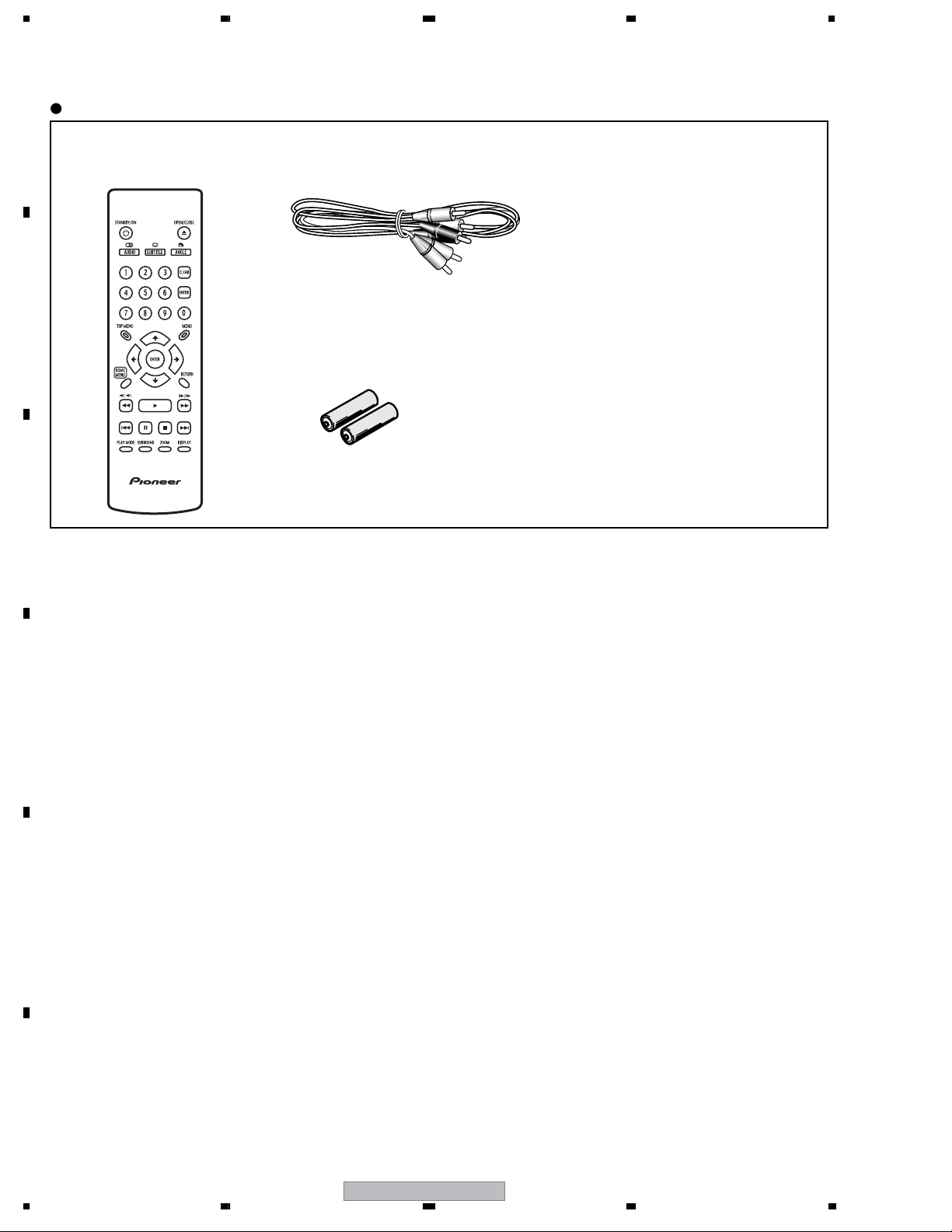
2.1 ACCESSORIES
Accessories
A
• Remote control ×1
(07650KY060)
B
C
• Audio / Video cable(1.2m) ×1
(red/white/yellow)
(06CPBA2006)
• Dry cell batteries ×2
(AA/R6P)
• Warranty Card
• Operating Instructions
D
E
F
8
1234
DV-300-K

5678
2.2 SPECIFICATIONS
General
Power requirements . . . . . . . . . . . .AC 120 V, 60 Hz
Power consumption . . . . . . . . . . . . . . . . . . . . . .7 W
Power consumption (standby). . . . . . . . . . . . . 0.6 W
Weight . . . . . . . . . . . . . . . . . . . . . 1.8 kg (3 lb 16 oz)
Dimensions:
. . . . . . 420 mm (W) x 49.5 mm (H) x 215 mm (D)
(16-9/16 in. (W) x 1-15/16 in. (H) x 8-1/2 in. (D))
Operating temperature . . . . . . . . . . .+5 ºC to +35 ºC
(+41 ºF to +95 ºF)
Operating humidity. . . . . . . . . . . . . . . . . 5 % to 85 %
(no condensation)
Component video output (Y, PB, PR)
Output level . . . . . . . . .Y (luminance): 1 Vp-p (75 Ω)
PB (color): 0.7 Vp-p (75 Ω)
PR (color): 0.7 Vp-p (75 Ω)
Jacks. . . . . . . . . . . . . . . . . . . . . . . . . . . . . . . . . RCA
S-video output
Output level . . . . . . . . .Y (luminance): 1 Vp-p (75 Ω)
C (color): 286 mVp-p (75 Ω)
Jack . . . . . . . . . . . . . . . . . . . . . . . . . .4-pin mini DIN
Audio output (1 stereo pair)
Output level . . . . . . . . . . . . . . . .During audio output
200 mVrms (1 kHz, –20 dB)
Number of channels . . . . . . . . . . . . . . . . . . . . . . . .2
Jacks . . . . . . . . . . . . . . . . . . . . . . . . . . . . . . . . .RCA
Digital audio characteristics
Frequency response . . . . . . . . . . . . .4 Hz to 44 kHz
S/N ratio . . . . . . . . . . . . . . . . . . . . . . . . . . . . .115 dB
Dynamic range . . . . . . . . . . . . . . . . . . . . . . . . .88 dB
Total harmonic distortion . . . . . . . . . . . . . . 0.0065 %
Wow and flutter . . . . . . . . . . . .Limit of measurement
(±0.001 % W. PEAK) or lower
Digital output
Coaxial digital output . . . . . . . . . . . . . . . . . . . . .RCA
Accessories
Remote control . . . . . . . . . . . . . . . . . . . . . . . . . . . .1
AA/R6P dry cell batteries . . . . . . . . . . . . . . . . . . . .2
Audio/video cable (red/white/yellow plugs) . . . . . . .1
Warranty card . . . . . . . . . . . . . . . . . . . . . . . . . . . . .1
Operating instructions
A
B
C
Video output
Output level. . . . . . . . . . . . . . . . . . . . . 1 Vp-p (75 Ω)
Jack . . . . . . . . . . . . . . . . . . . . . . . . . . . . . . . . . RCA
The specifications and design of this product are subject
to change without notice, due to improvement.
D
E
56
DV-300-K
F
9
7
8
1234
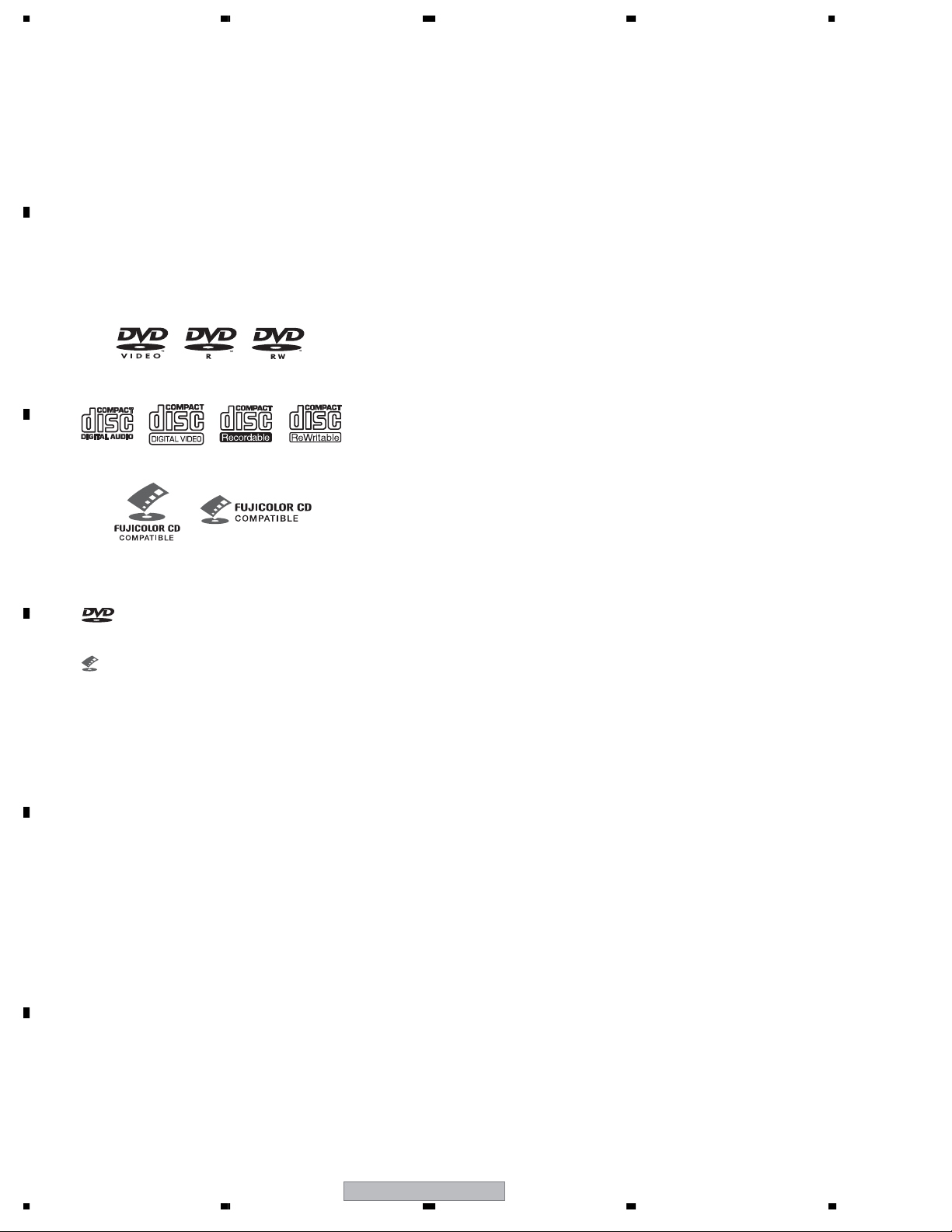
2.3 DISC/CONTENT FORMAT
Disc / content format playback
compatibility
A
This player is compatible with a wide range of
disc types (media) and formats. Playable discs
will generally feature one of the following logos
on the disc and/or disc packaging. Note
however that some disc types, such as
recordable CD and DVD, may be in an
unplayable format –see below for further
compatibility information.
Please also note that recordable discs cannot be
recorded using this player.
B
DVD-Video DVD-R DVD-RW
Audio CD CD-R
C
Video CD
Fujicolor CD
• This unit will play DVD+R/+RW discs.
• is a trademark of DVD Format/Logo
Licensing Corporation.
CD-RW
About DualDisc playback
A DualDisc is a new two -sided disc, one side
of which contains DVD content video, audio,
etc. while the other side contains non-DVD
content such as digital audio material.
The non-DVD, audio side of the disc is not
compliant with the CD Audio specification and
therefore may not play.
The DVD side of a DualDisc plays in this
product.
For more detailed information on the DualDisc
specification, please refer to the disc
manufacturer or disc retailer.
CD-R/RW compatibility
• Compatible formats: CD-Audio, Video CD/
Super VCD, ISO 9660 CD-ROM*
containing MP3, WMA, JPEG or DivX video
files
* ISO 9660 Level 1 or 2 compliant. CD
physical format: Mode1, Mode2 XA Form1.
Romeo and Joliet file systems are both
compatible with this player.
• Multi-session playback: No
• Unfinalized disc playback: No
• File structure (may differ): Up to 299
folders on a disc; up to 648 folders and files
(combined) within each folder
• is a trademark of Fuji Photo Film Co. Ltd.
• Also compatible with KODAK Picture CD
D
E
F
DVD+R/DVD+RW compatibility
Only DVD+R/DVD+RW discs recorded in
'Video Mode (DVD Video Mode)' which have
been finalized, can be played back. However,
some editing made during the recording may
not be played back accurately.
DVD-R/RW compatibility
• Compatible formats: DVD-Video, Video
Recording (VR)*
* Edit points may not play exactly as edited;
screen may go momentarily blank at edited
points.
• Unfinalized playback: No
• WMA/MP3/JPEG file playback on DVD-R/
RW: No
10
DV-300-K
1234

5678
Compressed audio compatibility
• Compatible formats: MPEG-1 Audio Layer
3 (MP3), Windows Media Audio (WMA)
• Sampling rates: 32 kHz, 44.1 kHz or 48 kHz
• Bit-rates: Any (128 Kbps or higher
recommended)
• VBR (variable bit rate) MP3 playback: No
• VBR WMA playback: No
• WMA lossless encoding compatible: No
• DRM (Digital Rights Management)
compatible: Yes (DRM-protected audio
files will not play in this player.)
• File extensions: .mp3, .wma (these must
be used for the player to recognize MP3
and WMA files – do not use for other file
types)
WMA (Windows Media™ Audio)
compatibility
This player can playback Windows Media
Audio content.
WMA is an acronym for Windows Media Audio
and refers to an audio compression
technology developed by Microsoft
Corporation. WMA content can be encoded by
using Windows Media Player for Windows XP,
Windows Media Player 9 or Windows Media
Player 10 series.
Windows Media is trademark of Microsoft
Corporation.
This product includes technology owned by
Microsoft Corporation and cannot be used or
distributed without a license from Microsoft
Licensing, Inc.
DivX video compatibility
• Official DivX® Certified product.
• Plays all versions of DivX
®
6) with standard playback of DivX
DivX
®
video (including
®
media files.
• File extensions: .avi and .divx (these must
be used for the player to recognize DivX
video files). Note that all files with the .avi
extension are recognized as MPEG4, but not
all of these are necessarily DivX video files
and therefore may not be playable on this
player.
DivX, DivX Certified, and associated logos are
trademarks of DivX, Inc. and are used under
license.
JPEG file compatibility
• Compatible formats: Baseline JPEG and
EXIF 2.2* still image files up to a resolution
of 3072 x 2048.
*
File format used by digital still cameras.
• Progressive JPEG compatible: No
• File extensions: .jpg (must be used for the
player to recognize JPEG files – do not use
for other file types)
PC-created disc compatibility
Discs recorded using a personal computer
may not be playable in this unit due to the
setting of the application software used to
create the disc. In these particular instances,
check with the software publisher for more
detailed information.
Discs recorded in packet write mode (UDF
format) are not compatible with this player.
Check the DVD-R/RW or CD-R/RW software
disc boxes for additional compatibility
information.
A
B
C
D
E
56
DV-300-K
F
11
7
8
1234
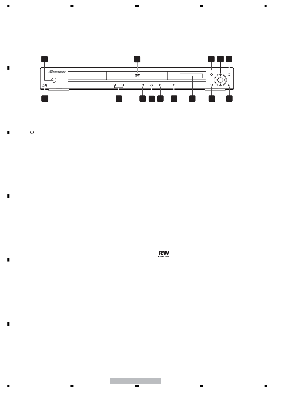
2.4 PANEL FACILITIES
2.4.1 FRONT PANEL SECTION
A
Front panel
1
STANDBY/
ON
B
1 STANDBY/ON
Press to switch the player on or into standby.
2 Disc tray
C
D
Displays the ‘top menu’ of a DVD
disc—this varies with the disc.
4
ENTER & cursor buttons
Selects the current menu option.
5
MENU
Displays a DVD disc menu—this varies with the disc
and may be the same as the ‘top menu’.
6 RETURN
Returns to the previously dis-played menu screen.
TOP MENU
3
7 HOME MENU
2
1213
3 4 5
MENUTOP MENU
ENTER
OPEN/CLOSE
11
HOME
MENU
RETURN
6781014 9
9 OPEN/CLOSE
Press to open or close the disc tray.
10
Press to start or resume playback.
11
Press to pause playback. Press again to
restart.
12
Press to stop the disc (you can resume playback by pressing (play)).
13 and
• Press and hold for fast reverse/forward
scanning.
• Press to jump to the previous/next
chapter or track.
E
F
12
8 Display
Description of the display.
1234
DV-300-K
15
Compatible
This mark indicates compatibility with
DVD-RW discs recorded on a DVD recorder
in
Video Recording mode.
5678
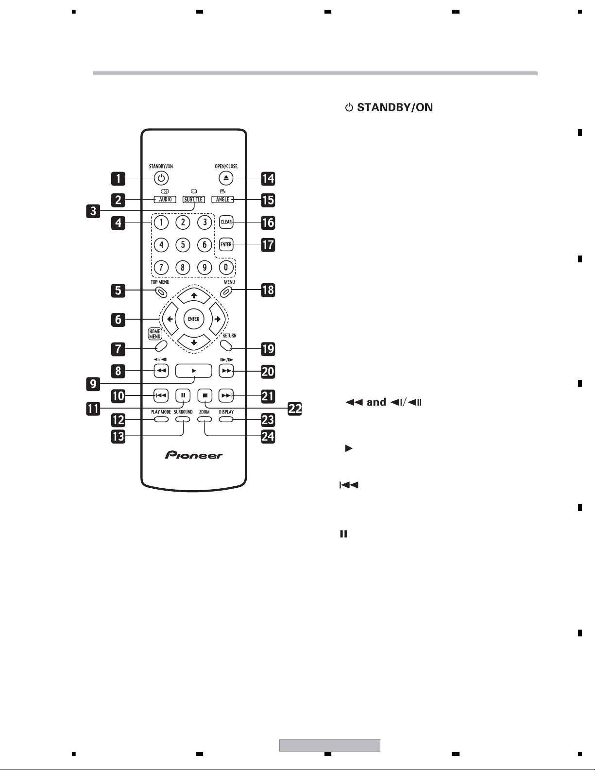
2.4.2 REMOTE CONTROL
Remote control
1
Press to switch the player on or into standby.
2AUDIO
Press to select the audio channel or language.
3SUBTITLE
Press to select a subtitle display.
4Number buttons
5TOP MENU
Press to display the top menu of a DVD disc.
6ENTER & cursor buttons
Use to navigate on-screen displays and
menus. Press ENTER to select an option or
execute a command.
A
B
C
7 HOME MENU
Press to display (or exit) the on-screen
display.
8
Use for reverse slow motion playback, frame
reverse and reverse scanning.
9
Press to start or resume playback.
10
chapter or track, then to previous chapters/
tracks.
11
Press to pause playback; press again to
restart.
12 PLAY MODE
Press to display the Play Mode menu. (You
can also get to the Play Mode menu by
pressing HOME MENU and selecting Play
Mode).
D
E
Press to jump to the beginning of the current
DV-300-K
56
F
13
7
8

1234
Remote control 2
A
13 SURROUND
Press to activate/switch off 2V/SRS TruSurround.
14
Press to open or close the disc tray.
15 ANGLE
Press to change the camera angle during
DVD multi-angle scene playback.
B
16 CLEAR
Press to clear a numeric entry.
17 ENTER
Use to select menu options, etc.
18 MENU
Press to display a DVD disc menu, or the Disc
C
Navigator if a VR format DVD-RW, CD, Video
CD , MP3, WMA or JPEG disc is loaded.
19 RETURN
Press to return to a previous menu screen.
20
Use for forward slow motion playback, frame
advance and forward scanning.
21
Press to jump to the next chapter or track.
22
Press to stop the disc (you can resume playback
by pressing (play)).
23 DISPLAY
Press to display information about the disc
playing.
24 ZOOM
Press to change the zoom level.
D
E
F
14
DV-300-K
1234
5678
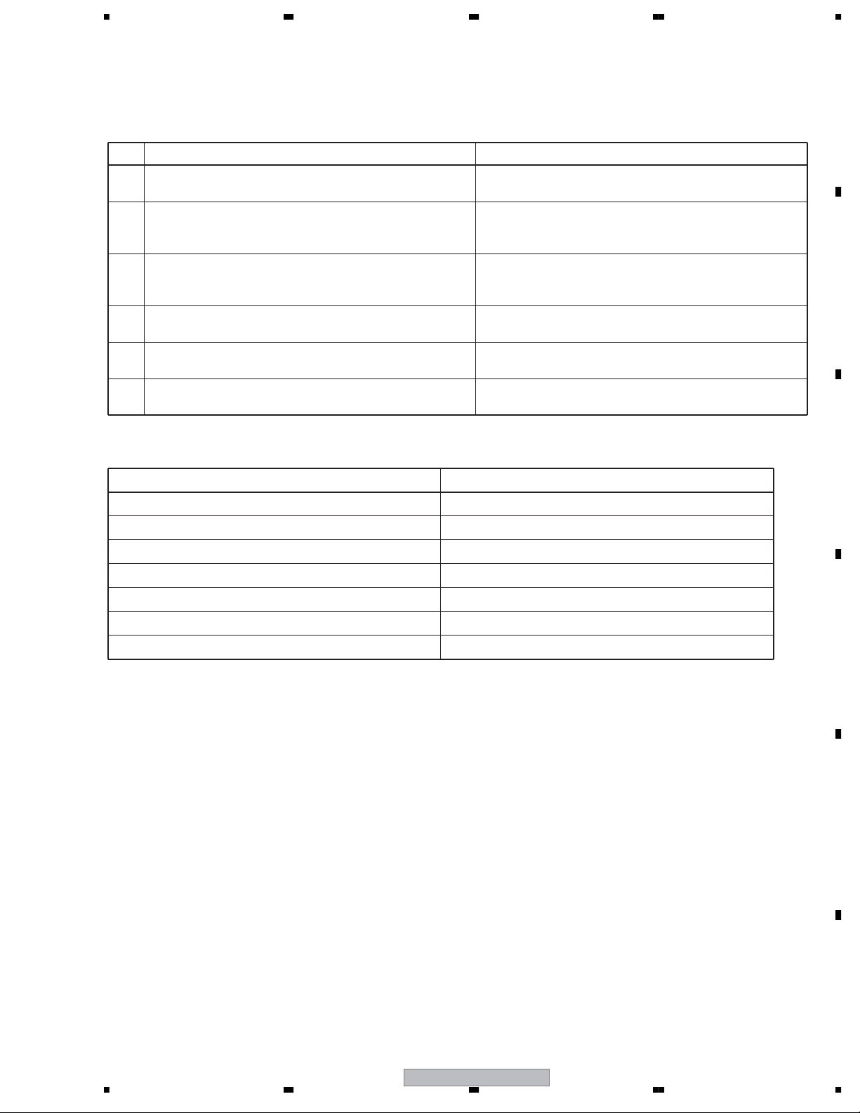
3. BASIC ITEMS FOR SERVICE
3.1 CHECK POINTS AFTER SERVICING
Check points after servicing (DVD player)
To keep the product quality after servicing, confirm recommended check points shown below.
No. Procedure Check points
1 Confirm the firmware version on Service Mode. The version of the firmware must be latest.
Update firmware to the latest one, if it is not the latest.
Confirm whether the customer complain has been solved.
2
If the customer complain occurs with the specific disc,
use it for the operation check.
Confirm playback error rates at the innermost and
3
outermost tracks by using the following disc.
DVD test disc (GGV1025)
Play back a DVD.
4
(Menu operation, Title/chapter search)
Play back a DVD.
5
(Menu operation, Title/chapter search)
Check the appearance of the product. No scratches or dirt on its appearance after receiving it
6
See the table below for the items to be checked regarding video and audio:
Items to be checked regarding video Item to be checked regarding audio
Block noise Distortion
The customer complain must not be reappeared.
Video, audio and operations must be normal.
The error rates must be less than 5.0e-4.
Audio and operations must be normal.
Video, audio and operations must be normal.
for service.
A
B
C
Horizontal noise Noise
Dot noise Volume too low
Disturbed image (video jumpiness) Volume too high
Too dark Volume fluctuating
Too bright Sound interrupted
Mottled color
D
E
56
DV-300-K
F
15
7
8
1234
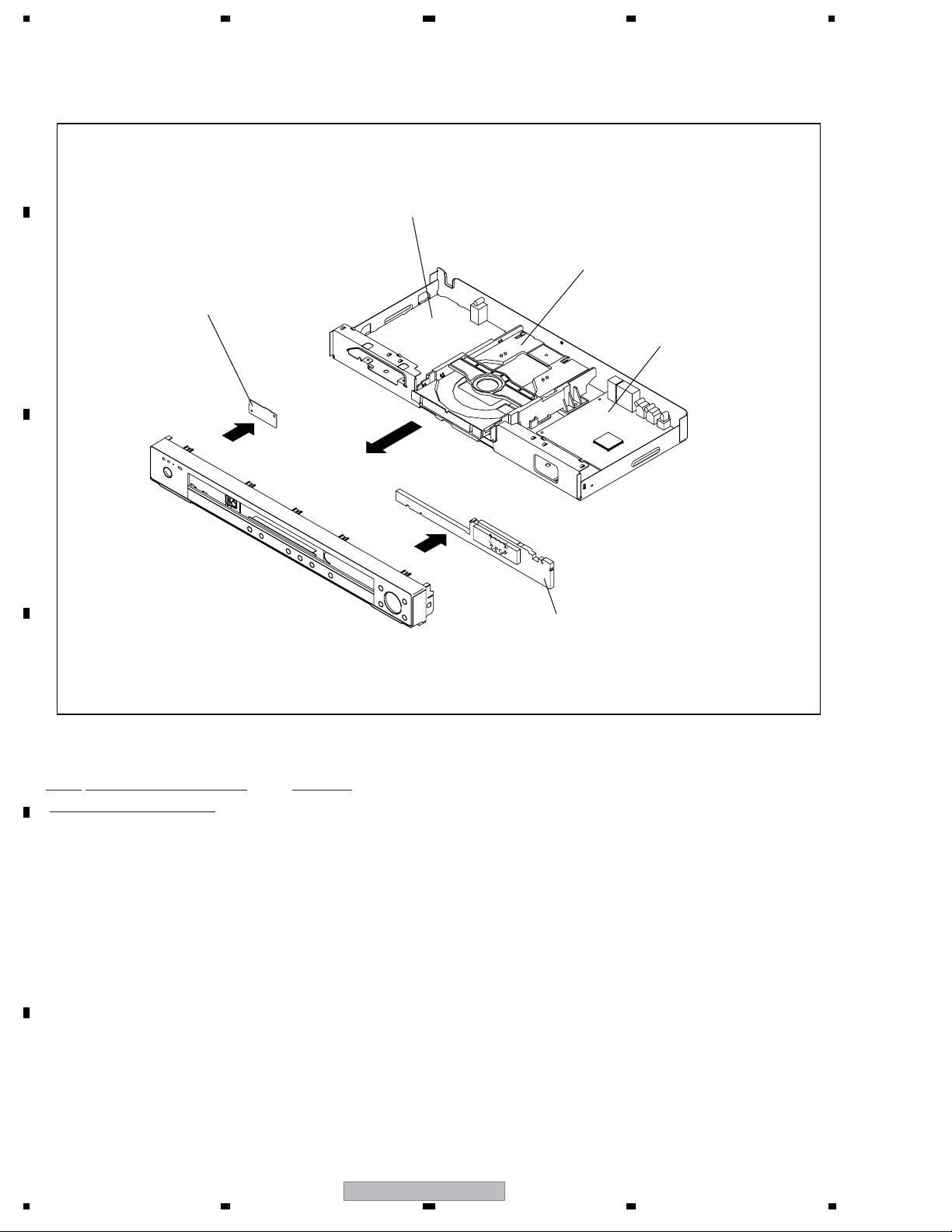
3.2 PCB LOCATIONS
A
POWER PCB ASSY
DVD MECHA ASSY
B
OPERATION 2 PCB ASSY
DVD MT PCB ASSY
C
OPERATION 1 PCB ASSY
D
Mark
No. Description Part No.
LIST OF ASSEMBLIES
1..DVD MT PCB ASSY A2K008A130
1..OPERATION 1 PCB ASSY A2K008A270
1..OPERATION 2 PCB ASSY A2K001A280
E
> 1..POWER PCB ASSSY A2K008A240
1..DVD MECHA ASSY A2K001A650
F
16
1234
DV-300-K
5678
3.3 JIGS LIST
7 Jigs list
Name Jig No. Remarks
Service Remote Control Unit GGF1381 diagnosis
DVD Test Disc (DVDDVD Test Disc (DVD-Video,PAL)
CD Test Disc
Video,NTSC)
GGV1025 Operation Check
GGV-1101
STD-905
Operation Check
Operation Check
Lubricants and Glues list
Name Lubricants and Glues No. RemarkName Lubricants and Glues No. Remark
Daifree GEM1036 (ZLX-ME413A) Refer to "9.3 06 DVD MECHA SECTION"
Grease GYA1001 (ZLB-PN397B) Refer to "9.3 06 DVD MECHA SECTION"
Grease GEM1018 Refer to "9.3 06 DVD MECHA SECTION"
Cleaning
• Before shipping out the product, be sure to clean the following positions by using the prescribed cleaning tools:
Position to be cleaned Cleaning tools RemarkPosition to be cleaned Cleaning tools Remark
Pickup leneses Cleaning liquid : GEM1004
Cleaning paper : GED-008
A
B
C
D
E
F
56
DV-300-K
17
7
8

1234
4. BLOCK DIAGRAM
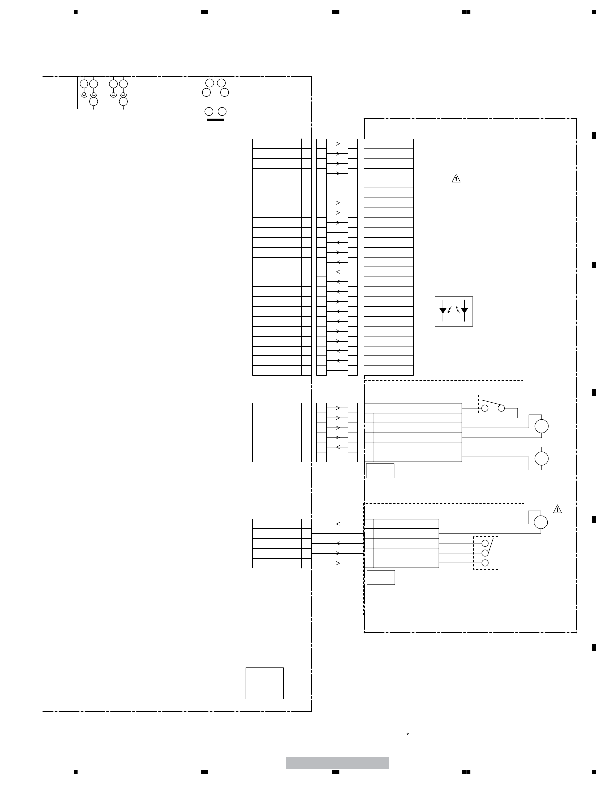
4.1 OVERALL WIRING CONNECTION DIAGRAM
A
OPERATION 2
PCB ASSY (A2K001A280)
B
POWER
OPERATION2 PCB
PCB280
C
DEF129
SW2
CP605_1
1
2
1
2
FFC
CD604_1
OPERATION 1 PCB ASSY
(A2K008A270)
CP601
CLK
DI (M to F)
STB
DO (F to M)
IR
V+3E
DGND
DGND
FLDC+
-28V
FLDC-
OPERATION1 PCB
PCB270
DEF126
1
2
CP604_1
1
2
OS651
SW2
POWER
B+
GND
2
3
Vout
1
H
2
1
E
COAXIAL
J8001
(CD601)
1
1
2
2
3
3
4
4
5
5
6
6
7
7
8
8
9
9
10
10
11
11
CP4002
1
2
3
4
5
6
7
8
9
10
11
CLK
DI (M to F)
STB
DO (F to M)
IR
V+3E
DGND
DGND
FLDC+
-28V
FLDC-
1
2
3
4
5
6
7
8
9
10
11
H1H2
23
1
E
AUDIO OUT
J8003
POWER PCB ASSY
AC120V_60Hz(US)
D
CD501
BLADE
WIDE
WHITE
BLACK
CP501
WHITE
21
1 2
BLACK
E
POWER PCB
PCB024
DPF015
F
CAUTION
:SINCE THESE PARTS MARKED BY
18
1234
(A2K008A240)
CRITICAL FOR SAFETY,USE ONES
DESCRIBED IN PARTS LIST ONLY
DV-300-K
CP502
GND
P.CON+12V
AT+12V for MUTE
GND
P.CON+5V
P.CON+6V
GND(M)
AT+3.3V
P.ON-H(STBY L)
GND(D)
FL DCFL DC+
-28V
ARE
ATTENTION
(CD502)
1
1
2
2
3
3
4
4
5
5
6
6
7
7
8
8
9
9
10
10
11
11
12
12
13
13
14
14
CP4003
1
2
3
4
5
6
7
8
9
10
11
12
13
14
GND
1
P.CON+12V
2
AT+12V for MUTE
3
GND
4
P.CON+5V
5
P.CON+6V
6
GND(M)
7
AT+3.3VAT+3.3V
8
AT+3.3V
9
P.ON-H
10
GND(D)
11
FL DC-
12
FL DC+
13
-28V
14
:LES PIECES REPAREES PAR UN ETANT
DANGEREUSES AN POINT DE VUE SECURITE
N'UTILISER QUE CELLS DECRITES
DANS LA NOMENCLATURE DES PIECES
5678
23
1
E
CVBS/Y/U/V
J7302
H1H2EH1H2
56
4
34
12
56
S-VIDEO OUT
J7301
DVD MT PCB ASSY (1/6 – 6/6)
(A2K008A130)
FOCS RTN
FOCS DRV
TRKG RTN
TRKG DRV
NC
GND
LD_DVD(650)
PD/GND
LD_CD(780)
GND
VR780(CD)
VRCOM
VR650(DVD)
A
B
VRF(RF_OUT)
SW1(DVD/CD)
C
D
E
VCC
VS
F
GND
CP2303
SW(GND)
LIMIT SW
SLDSLD+
SPDSPD+
CP2301
24
23
22
21
20
19
18
17
16
15
14
13
12
11
10
9
8
7
6
5
4
3
2
1
6
5
4
3
2
1
A
24
23
22
21
20
19
18
17
16
15
14
13
12
11
10
9
8
7
6
5
4
3
2
1
6
5
4
3
2
1
24
23
22
21
20
19
18
17
16
15
14
13
12
11
10
9
8
7
6
5
4
3
2
1
1
2
3
4
5
6
FOCS RTN
FOCS DRV
TRKG RTN
TRKG DRV
NC
GND
LD_DVD(650)
PD/GND
LD_CD(780)
GND
VR780(CD)
VRCOM
VR650(DVD)
A
B
VRF(RF_OUT)
SW1(DVD/CD)
C
D
E
VCC
VS
F
GND
CD2301
2H061605
1
PICK UO INNER LIMIT SWITCH
2
FEED MOTOR(-)
3
FEED MOTOR(+)
4
5
SPINDLE MOTOR(-)
SPINDLE MOTOR(+)
6
PCB640
DED020
OPTICAL PICK-UP
GND(SW)
DVD
DRIVE
DM-4PB
(SW PCB)
SW2
ESE22MH22
M
M
M2602
BCZ3B05
M2601
JCV9B12
B
C
D
(LOADING MOTOR PCB)
CP2302
LOADLOAD+
OPEN
GND
CLOSE
DVD MT PCB
PCB130
DMF089
5
4
3
2
1
OF PRINTING AND SUBJECT TO CHANGE WITHOUT NOTICE
DV-300-K
56
CD2302
2H051602
1
LOADING MOTOR(-)
2
LOADING MOTOR(-)
3
SW-1(OPEN)
4
5
SW-2(CLOSE)
PCB610
DED021
DVD MECHA ASSY
(A2K001A650)
GND(SW)
THE TIMETHIS INTERCONNECTION DIAGRAM IS THE LATEST ATNOTE:
7
SW1
SSS-28-5
M2603
M
BCZ3B05
E
F
19
8
1234
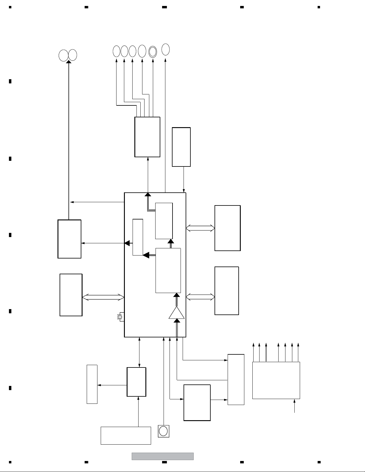
4.2 OVERALL BLOCK DIAGRAM
A
L
R
B
AMP_AUDIO_L/R
Y
V
U
CVBS
IC7301
VIDEO DRIVER 6CH IC
CO
S
S_VIDEO
COAXIAL
LA73054-TLM-E
IC4003
RESET IC
R3112N291A-TR-FA
TV Encoder
JPEG
VIDEO
DECORDER
RF
RESET
IC4005
64Mbit SDRAM
HY57V641620ETP-7-C
IC4004
16Mbit FLASH
ES29LV160EB-70TG
P. CON+12V
P. CON+5V
P. CON+6V
AT+3.3V
-28V
AT+12V for mute
FLDC+/-
CH VIDEO DAC
C
IC8003
RC4580IDR
AUDIO AMP
D
OVERALL BLOCK DIAGRAM
IC4002
EEPROM
S-24CS08AFJ-TB-1GE
AMUTE
AUDIO_L,
SDA, SCL
AUDIO_R
X4001
27MHz
AUDIO CODEC/
IC4001
BLOCK
MPEG/MICON
INTERNAL DAC
MT1389FE/E-L
ASPDIF
108MHz
MPEG-1/2/
E
LD_DVD,
FP,STB
LD_CD
FIP
HNV-08SS44T
IC651
PT6315
FIP DRIVER IC
SERVO
IR
F
IR
20
KEY
DV-300-K
ROM-N340TAO
IR RECEIVER (OS651)
RF
IC2301
AM5766
MOTOR DRIVER
(DM4)
DVD LOADER
SERVO
POWER
SUPPLY
AC120V
1234
5678
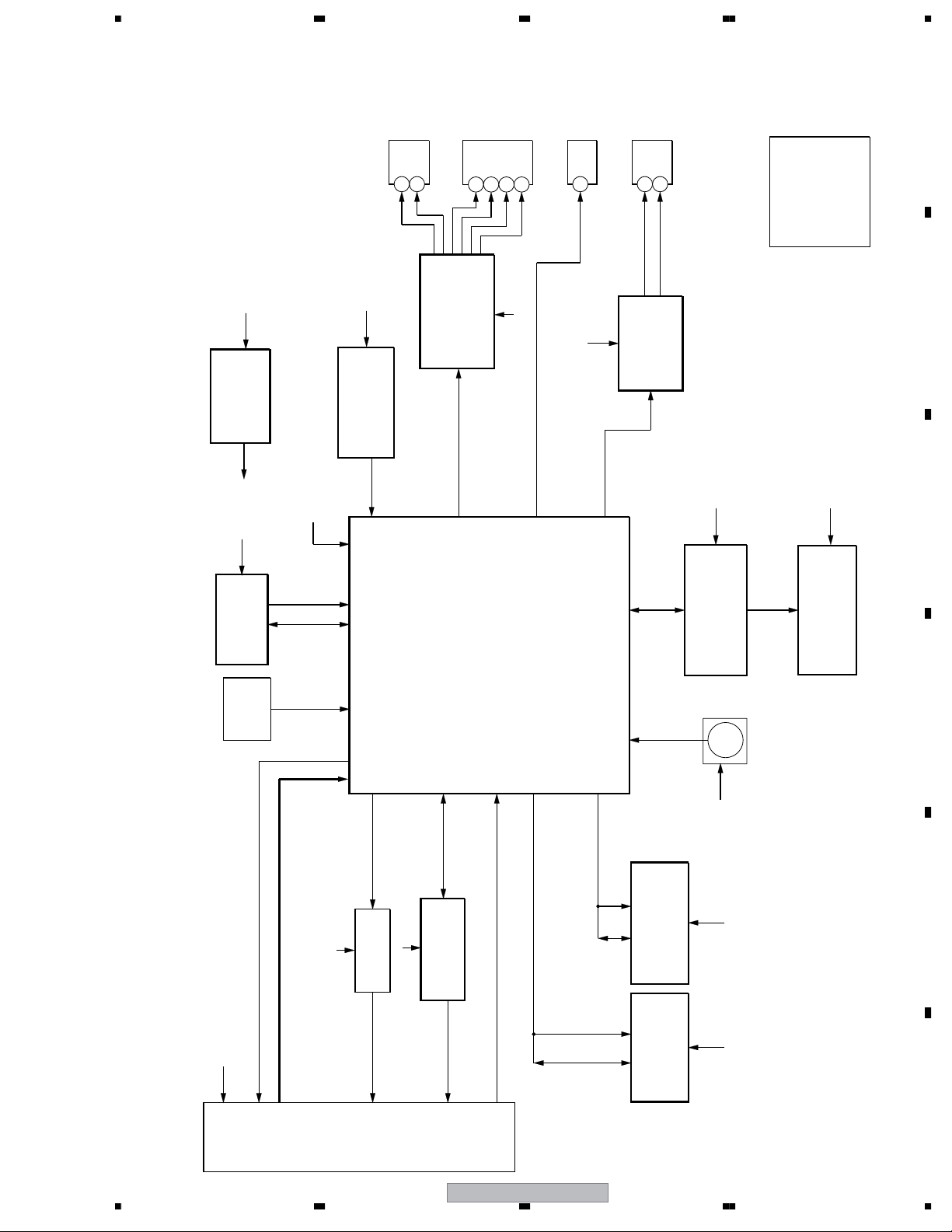
4.3 DVD LOADER BLOCK DIAGRAM
Y
S-VIDEO JACK
J7301
C
4
3
VIDEO JACK
J7302
Y
5
A
R
U
V
CVBS
COAXIAL JACK
3
2
J8001
6
AUDIO JACK
2
J8003
AUDIO R
L
3
2
.......AT+3.3V
.......+1.8V
.......P.CON+5V
.......P.CON+6V
.......AT+12V
.......P.CON+12V
ABCDEFG
AUDI O L
.......-28V
A
IC4006
REG+1.8V
LM1117S-ADJ
B
A
IC4002
EEPROM IC
S-24CS08AFJ-
X4001
27MHz
TB-1GE
SDA SCL
A, B
A
IC4003
RESET IC
R3112N291A-TR-FA
RESET
IC7301
LA73054-TLM-E
VIDEO DRIVER 6CH IC
LETTER, SQUEEZE, VSEL1,
I/XP, R/CR, B/CB, G/Y, C/V
IC4001
MT1389FE/E-L
MPEG/MICON IC
C
ASPDIF
F
AUDIO L, R
IC8003
AUDI O AMP IC
FP_DI, FP_DO,
RC4580IDR
FP_SCK, STB
IC651
IR
A
PT6315
FIP DRIVER IC
IR
G
GR1 ~ GR8,P1~P16
FIP (V651)
HNV-08SS44T
B
C
D
DVD LOADER/MPEG BLOCK DIAGRAM
STBY, V1P4
TRSO, FOSO,
DMSO, FMSO,
TROPEN, TRCLOSE,
D
IC2301
AM5766
MOTOR DRIVER IC
T+/-, F+/-,
LOAD+/-,
MOT_SPDL+/-
MOT_SLED+/-,
SLED
SPINDLE/
STEPING/
MA0~MA11, DQ0~DQ15,
DQM0, DQM1, DBA0, DBA1,
SDCLK, SDCKE, DWE#,
DRAS#, DCAS#, DCS#
LIMIT, TRIN, TROUT,
A0-A20, AD0-AD7,
PRD#, PCE#, PWR#
MOTOR
C
DVD
Loader
(DM-4)
IOA, V20
RF, A, B, C, D, E, F, MDI1
A
OPU
LDO1, LDO2
LD DRIVE
Q2302-2305
LD_DVD, LD_CD
DV-300-K
56
7
IC4005
64Mbit SDRAM
HY57V641620ETP-7-C
IC4004
16Mbit FLASH
ES29LV160EB-70TG
ROM-N340TAO
IR RECEIVER (OS651)
A
A
A
E
F
21
8
 Loading...