

Page 1

Aviosys
DTV 6010
TV TUNER CARD
OPERATING INSTRUCTIONS
DISTRIBUTED BY PIONEER EUROPE
For Pioneer PDP 503MXE / 433MXE
Page 2
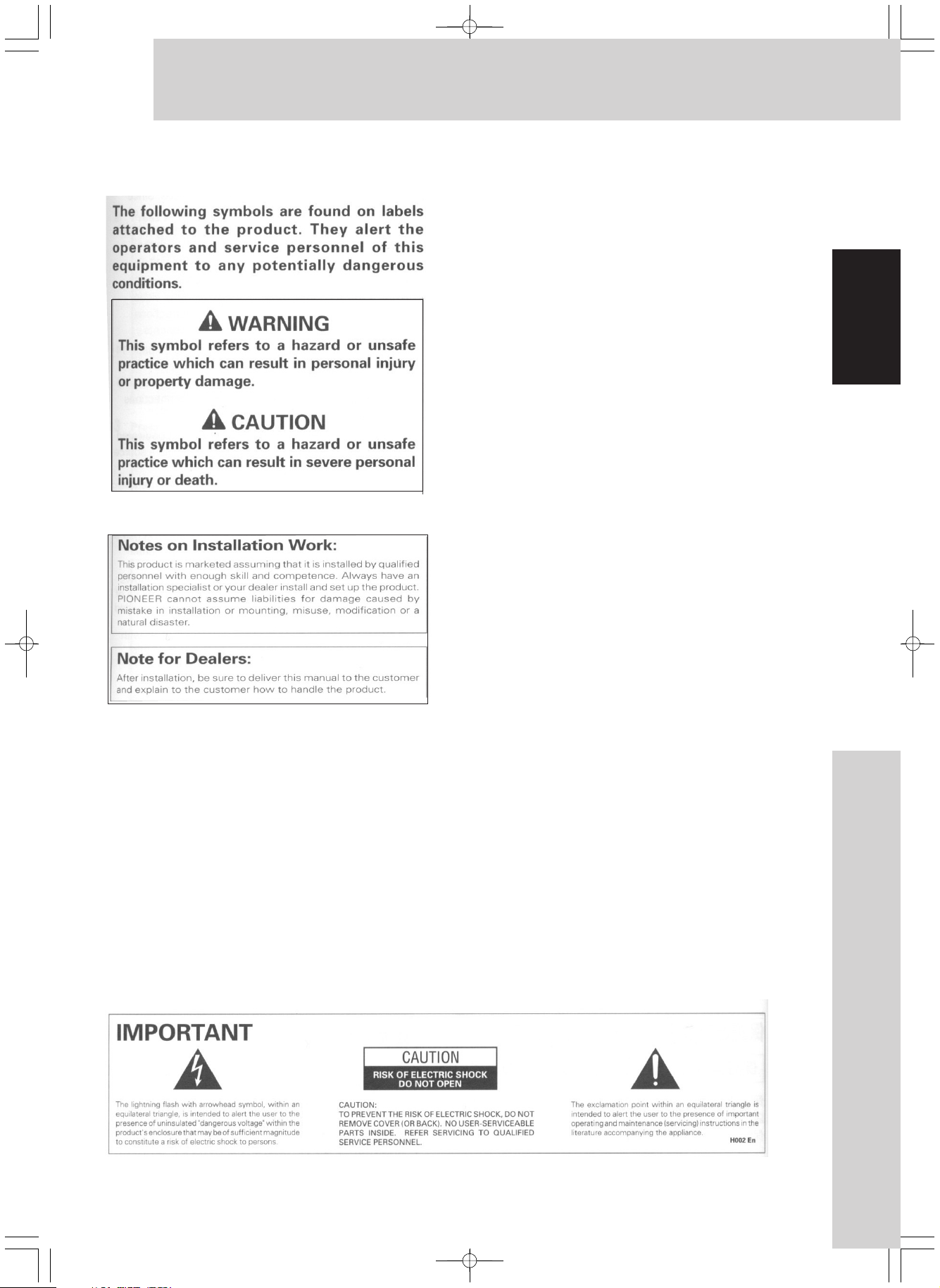
Safety & Warning
Thank you very much for purchasing AVIOSYS
product ,before using this DTV 6010, please
carefully read the above warning information
and the "Before Use" , so you will know how to
operate the TV Tuner card with Plasma
Display properly.
Keep the manual in safe place you will find it
very useful in the future.
The DTV 6010 TV Tuner Card is exclusively
used for PIONEER PDP 503MXE & 433 MXE,
and distributed by PIONEER EUROPE .
The PDP-503MXE & PDP-433MXE Plasma
display has been originally designed as a
computer monitor , but by installing the optional
DTV 6010TV Tuner Card , the following features
are available::
1. Allows use of additional input jacks(INPUT
3,4,5) supporting TV, SCART, and DVI signal.
2. Allows connection to a wide variety of optional
video equipment.
English
1
1
Safety & Warning
Page 3

Contents
Contents....................................1
Safety ...................................... ................
Contents ................. ..............................
DTV6010 Features... ...............................
Before Use.................................3
Information for Your Safety......... .................
ackage contents / Supply Accessories
P ......
Connection names and Function....................
English
Remote Controller ................ . ...................
Watching TV.............................. 13
TV fast key and function........ .................... .
Display Current System Information ...........
Change Main-Picture Format.......................... ..
Change Audio Format ......................... ......
Advance Operation ...................................
Open/Close PIP Mode............................. .
Switch round PIP Modes ......................... ..
PIP Mode................................. 14
Set Main Source.......................................
Move Sub-Picture.....................................
Page Down Sub-Pictures ....................... ..
Swap Main Input Source with Sub-Picture..
Fade in/ out Sub-Picture ..........................
Freeze the Main screen............................
Tile 12 Mode............................ . 15
Set Main Source.......................................
Select a Sub-Picture.................................
Full Screen the sub picture ..................... .
Page Down Sub-Pictures ..........................
Display Continuous Pictures......................
Freeze the Main screen............................
Tile 16 Mode............................ . 16
Page down Sub-Pictures..................... .....
SWAP video source in Tile 16.....................
Select a Sub-Pictures........................... ....
Full screen the selected Sub-Pictures.... . ..
TV MENU
List of TV MENU................... 19
Main Picture.............................20
Adjusting Main-Picture Parameters.......
Adjusting Main-Picture Scale................
Setting Main-Picture Film Mode ...........
Setting Main-Picture Noise Filter..........
Sub-Picture...........................22
PIP Mode Set...........................................
Adjusting Sub-Picture Parameters.............
Adjusting Sub-Picture Position.................
Fade in/out Sub-Picture...........................
Adjusting PIP Size..................................
Set Sub-Picture Aspect........................
TV.........................................25
PreSet Channel...................................
Channel Name Edit..............................
Channels Swap...................... .............
Manual Tuning.....................................
Fast AutoTuning...................................
Addition Channel... ...............................
Delete Channel...... .................. ............
SETUP...................................27
Timing Set......... .................................
Format Set ........ .................................
Country Set ....... .................................
On Screen Langrage Display.................
SCART Colour Set ............ ..................
SCART IN Set..................... .................
GAMMAADJUST.............................. ....
RESET System ................................ ....
MISC.....................................28
DEMO ................................................
Addtional Information----------- 29
TELETEXT Mode....................... .17
Switch among TV/ Text Mode . ..................
Display Index Page.................. ...............
Display Text Page .................. . .............
Hold On/ Off Current Page ..... .................
Reveal Concealed Characters .................
List Mode on/off ......................... ............
Display Subtitle Text Page ........... ...........
Expand Current Page .................. ...........
Clock........................................................
Contents
2
Page 4

Features Before Use
Features
235
DTV6010 provides the following features :
Pan-Euro Standard TV Input PAL I/DK/BG
Pan-Euro, Cyrillic, Arabic, Enhanced Closed
Caption Teletext System with FastKey support
Flexible Configuration for various video input
source include Video/ S-Video/ RGB/ DV I
Auto Tune
Friendly Multi-Language OSD interface for MAIN
and PIP display controls
Flexible MAIN/PIP Configuration :
Multiple PIP (Picture in Picture), Up to 16 PIP
windows supported
Motion adaptive de-interlacing or inverse 3:2/2:2
pull-down de-interlacing on Main channel
Arbitrary shrink/zoom scaling on both MAIN and PIP
Information for Your Safety
Carefully read the Operating Instructions
and use the DTV6010 correctly.
Injury or material damages resulting from any kind
of use that is not in accordance with the operating
procedures explained in this Instructions , is the
sole responsibility of the user.
WARNING
Unpack the contents of the package. To avoid
any damage to your card by static-sensitive
electricity discharge, please keep the card in its
static -resistant bag until needed and avoid
touching the electronic components or the printed
circuit boards with your fingers.
WARRANTY
Your dealer will have explained the warranty
conditions of this product to you at the time of
purchase. Please refer any problem to your
dealer or authorised service centre.
English
Instantaneous MAIN/PIP swapping.
Adjustable Contrast/ Brightness/ TINT/ Colour/
Sharpness on both Main and Sub Picture
Adjustable Main-Picture Scale
Adjustable PIP-Blending levels of PIP display
Adjustable PIP-Position
Adjustable PIP-Size
Flexible PIP Mode :
One/ PAP/ Tile1/12 / Tile0/16
Flexible PIP format : 16:9 Expand, 4:3 Expand
Flexible Main Picture Display Format :
16:9 WIDE / 16:9 FULL , 4:3 , 16:9 ZOOM
Supports Pan-Euro NICAM/ IGR Digital Audio
TV system
Remote Control Fully Compatible 503MXE Plasma
Remote Controller
Record th e place and date for purchase
For future reference
Dealer -------------Model No --------------Serial No --------------Purchase date ---------------
Product Covered
DTV 6010 card
What Not Covered
The warranty card only covers failures due to defects
in parts and workmanship which occur under normal
use conditions.
The warranty does not cover DTV 6010 cards which
have been damaged as a result of alterations
modification not authorised by Aviosys , accident ,
misuse or abuse, damage due to lightning or
power surges. The warranty also does not cover
any damage caused to the Remote Control by the
use of damage batteries or batteries not
confirming to those specified in the
operation instructions.
COPYRIGHT c 2003 AVIOSYS
All trade mark mention in this document are the
property of their respective owner. Aviosys reserve
all the right to make changes or revision in the
product design or the product specifications
and manual with out reservation and with out
obligation to notify any person of such revision or
changes.
All rights reserve.
3
Features Before Use
Page 5
Before Use
Instruction Manual PEE-018
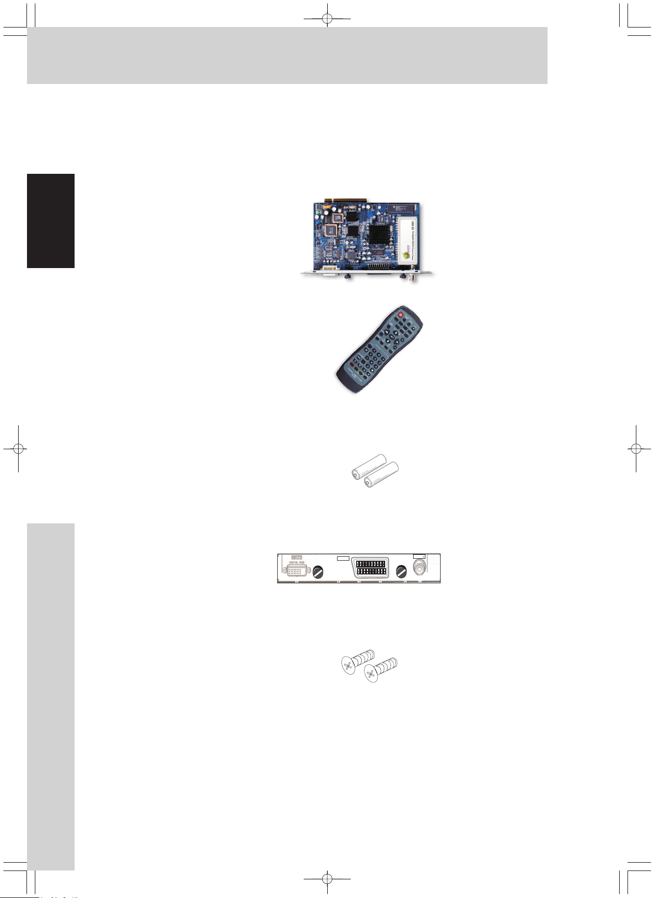
Package contents / Supply Accessories
Check the following contents of the package:
1. DTV 6010 PCB
English
2. Remote control
3. Battery AAA(x 2)
4. Connector indicator Label
5. Screws X 2
INPUT4
SCART
AVIOSYS DTV 6010
INPUT3
TV
6. Instruction Manual
SERVICE PART LIST:
DESCRIPTION P ART NUMBER
Remote control unit PEE-002
DTV6010PCB PEE-003
Before Use
4
Page 6
Connectors Names and Functions
16
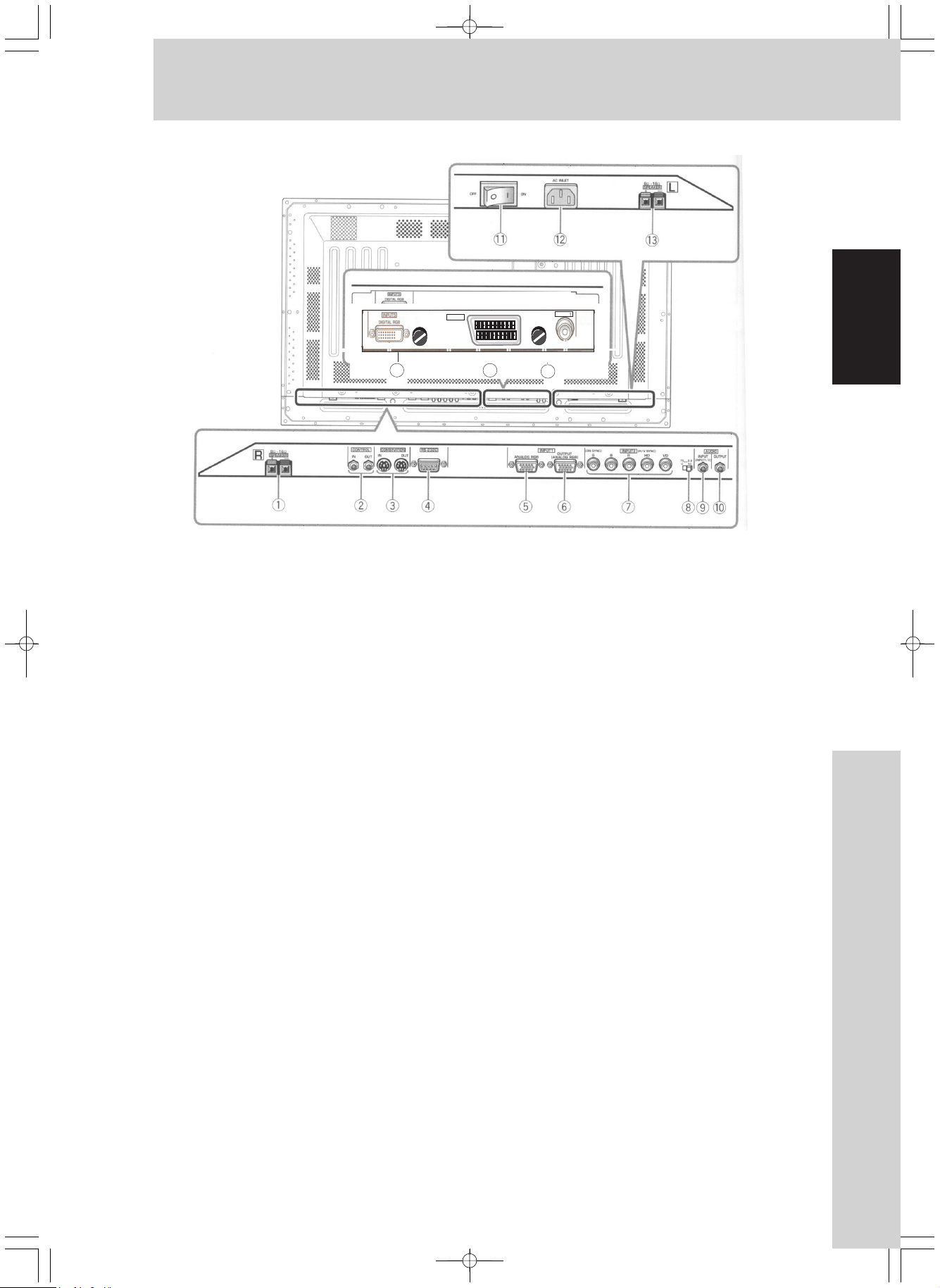
Plasma Display Section
The plasma display is provided with 2 video input
connectors, 1 video output connector, audio input/
output jacks and speaker terminals.
There are also CONTROL IN/OUT jacks for
connection of PIONEER components with the SR
mark.
When this video card is installed on a plasma
display, an additional three sets of video input
connectors are provided (total five), together with
one additional video output connector (total two).
See the pages noted in parentheses or the plasma
display’s Operating Instructions for details regarding
connections to the various jacks and connectors.
(1) SPEAKER (R) Terminal
For connection of an external right speaker.
Connect a speaker whose impedance is 8
–16ohms.
(2)CONTROL IN/OUT (monaural mini jacks)
For connection of PIONEER components that bear
the SR mark. Making CONTROL connection
enables control of the plasma display as a
component in a system.
(3) COMBINATION IN/OUT
DO NOT MAKE ANY CONNECTIONS TO
THESE TERMINALS.
These terminal are used in the factory setup.
(4) RS-232C
DO NOT MAKE ANY CONNECTIONS TO
THIS TERMINAL.
This terminal is used in the factory setup.
INPUT4
SCART
AVIOSYS DTV 6010
INPUT3
TV
15
(5)INPUT1(miniD-sub15pin)
For connection of components that have RGB or
component output jacks such as a personal
computer, DVD player, or external RGB decoder.
Make sure that the connection made corresponds to
the format of the signal output from the connected
component (pages 7 to 10).
(6) OUTPUT (INPUT1) (mini D-sub 15 pin )
Use the OUTPUT (INPUT1) connector to output the
video signal to an external monitor to output the
video signal to an external monitor or other
component.
Note: The video signal will not be output from the
OUTPUT (INPUT1) connector when the main power
of this display is off or in standby mode. (page 10)
(7) INPUT2 (BNC jacks )
For connection of some components that have RGB
or component output jacks such as a personal
computer, DVD player, or external RGB decoder.
Make sure that the connection made corresponds to
the format of the signal output from the connected
component (pages 7 to 9).
8) Synchronizing signal impedance
Depending on the connections made at INPUT2, it
may be necessary to set this switch to match the
output impedance of the connected component’s
synchronization signal.
When the output impedance of the component’s
synchronization signal is above 75ohms, set this
switch to the 2.2 k position .
14
selector switch
English
5
Connectors Names and Functions
Page 7

Installation
Installing the Video Card
(9) AUDIO INPUT (Stereo mini jack)
Use to obtain sound when INPUT1, INPUT2 or
INPUT5 is selected.
Connect this jack to the audio output connector of the
device connected to the plasma display’s INPUT1 or
INPUT2, or to the audio output connector of the
device connected to the video card’s INPUT5
English
(10) AUDIO OUTPUT(Stereo mini jack)
Use to output the audio of the selected source
component connected to the plasma display to an AV
amplifier or similar component
(11) MAIN POWER switch
Use to switch the main power of the plasma display
on and off.
(12) AC INLET
A power cable is furnished with the plasma display:
connect one end of the power cable to this connector,
and the other end to a standard AC power source.
(13) SPEAKER (L) terminal
For connection of an external left speaker. Connect a
speaker that has an impedance of 8 -16 .
Video Card
<DTV 6010> Section
The video card is provided with 1 TV input connector,
1 SCART video input connector, and 1 DVI video
input connector.
(14) TV VIDEO INPUT3
Connect TV antenna to the TV input connectors of
components connected to the video card’s INPUT3 .
Note: This TV card is compatible with PAL BG / DK/ I
TV system .
TO USERS:
This component is sold with the understanding
that it will be installed by a specialist possessing
appropriate technical knowledge and ability.
USAGE GUIDELINES
All phosphor-based screens (including conventional
tube-type) can be affected by displaying static
images for a prolonged period. Plasma Display
Screens are no exception to the rule. After- image
and permanent effects on the screen can be avoided
by taking some basic precautions, which include
following the recommendations listed below:
Whenever possible, avoid frequently displaying the
same image or virtually still moving pictures. Do not
display Teletext for a prolonged period of time.
Avoid viewing the On Screen Display for extended
periods, from a decoder, DVD player, VCR or other
equipment.
Do not leave the same picture Freeze-framed or
paused continually over a long period of time. Do not
display the different Picture in Picture screens for a
prolonged period of time.
After displaying a PC image or any other still image,
it is recommended to view a normal moving picture in
the 'Wide' or 'Full' screen set for more than 3 times
the length of the previous still image.
TO SALES AGENTS:
Installation instructions are noted below. When
installing the unit, if a screw or other object should
drop inside the plasma display, immediately consult
your nearest Pioneer Service Center. Continuing
operation may result in malfunction.
This device has been designed for installation in
the Pioneer Plasma Display PDP- 433 MXE /
PDP-503MXE.
(15) SCART INPUT4
For connection of components that have a
SCART. S-video or Composite video output jack
such as a video deck, video camera, laser disc player,
or DVD player.
(14) DVI- I INPUT5
In the case of INPUT5 the DVI-I connector will only
accept digital information. (The analogue portion of
the connector is not connected)
Note: This unit does not support the display of
copy guard-protected video signals.
Installation
6
Page 8
Installation
Installation Notes:
Confirm the following before installing this video
card :
1. Disconnect the plasma display from computer
or other components.
2. Disconnect the plasma display’s power card
from its outlet.
3. When opening the installation cover, take care
not to drop screws or other objects in the
opening. Objects dropped inside the display
may cause damage or malfunction.
4. When installing the video card, if the plasma
display is laid with its screen side facing
down, the work surface should be flat and level,
and either the packing material, a
blanket, or other soft material should be
spread on the word surface first to protect the
screen. Take care to prevent scratches or
other damage to the unit from tools or other
objects. Never rest the display on a surface in
such a way that weight or pressure is placed
only on the screen surface.
5. This video card has been designed for exclusive
use with the Pioneer Plasma Display
PDP-503CMX/PDP-503MXE. Do not attempt
unauthorized modifications or alterations since
malfunction or damage may result.
6. Take care not to modify or damage the card’s
internal devices in any way.
7. Before installation, take precautions to eliminate
static electricity on your body. Do not touch the
card’s circuitry or devices.
8. When the DTV 6010 TV tuner card is installed,
some of the function keys on the plasma display
key pad will not function. (These function are
still available by remote control) These are the
AUTO SET UP and INPUT keys.
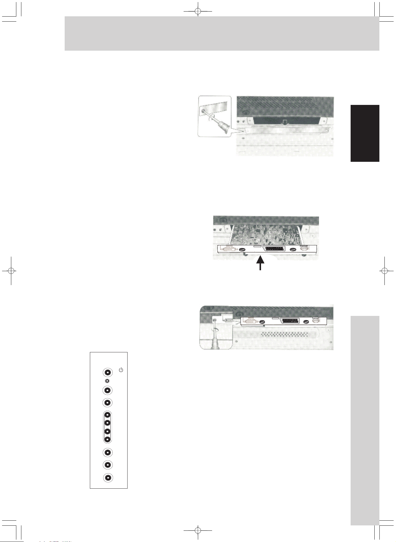
Installation:
1. Remove the protective cover over the video card
slot on the terminal panel of plasma display.
2 .Insert the video card gently and evenly in alignment
with the two rails (black) visible inside the installation
port.
Note
: Be very careful when inserting the card.
Insert straight! The card or display may be damaged
if thecard is inserted crooked or with excessive force.
INPUT4
SCART
AVIOSYSDTV 6010
INPUT3
TV
3. After inserting the video card all the way into the slot,
confirm that it is seated securely, then use the screws
removed in step 1 to or supplied in the carton to secure
the card in place.
INPUT4
SCART
AVIOSYS DTV 6010
INPUT3
TV
English
STANDBY/ ON
INPUT
MENU
ADJUST
SET
SCREEN SIZE
AUTO SETUP
Video Card Removal
1 Remove the two screws holding the video card.
2 Holding the inside tabs, pull the video card out
straight.
Setting the Integrator MENU
Switch on the main units power. The unit should
now be in standby mode.
Press the MENU key , then the standby key on the
remote control. The unit will now switch on and
Integrator MENU will be displayed. Using the cursor
keys select the OPTIONS tab and select SLOT INPUT.
Switch to COMPONENT 1 default is RGB. Whilst in
this menu, please do not attempt to make any other
adjustment . Press the menu key again to return
to normal operation.
7
Installation
Page 9
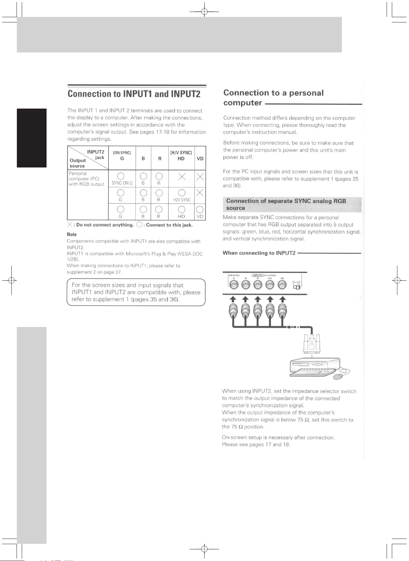
Input Connection
English
Input Connection
8
Page 10
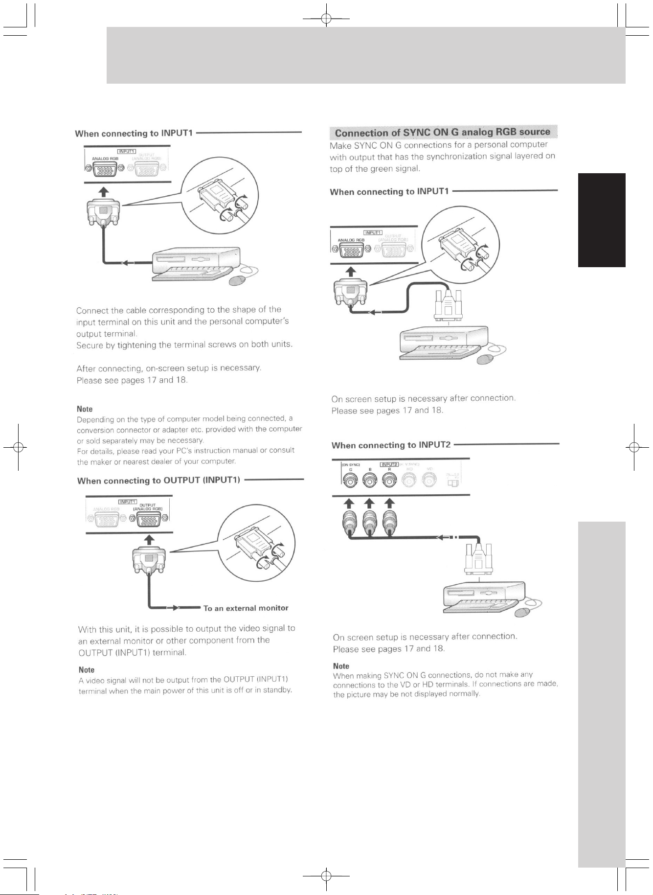
Input Connection
English
9
Input Connection
Page 11
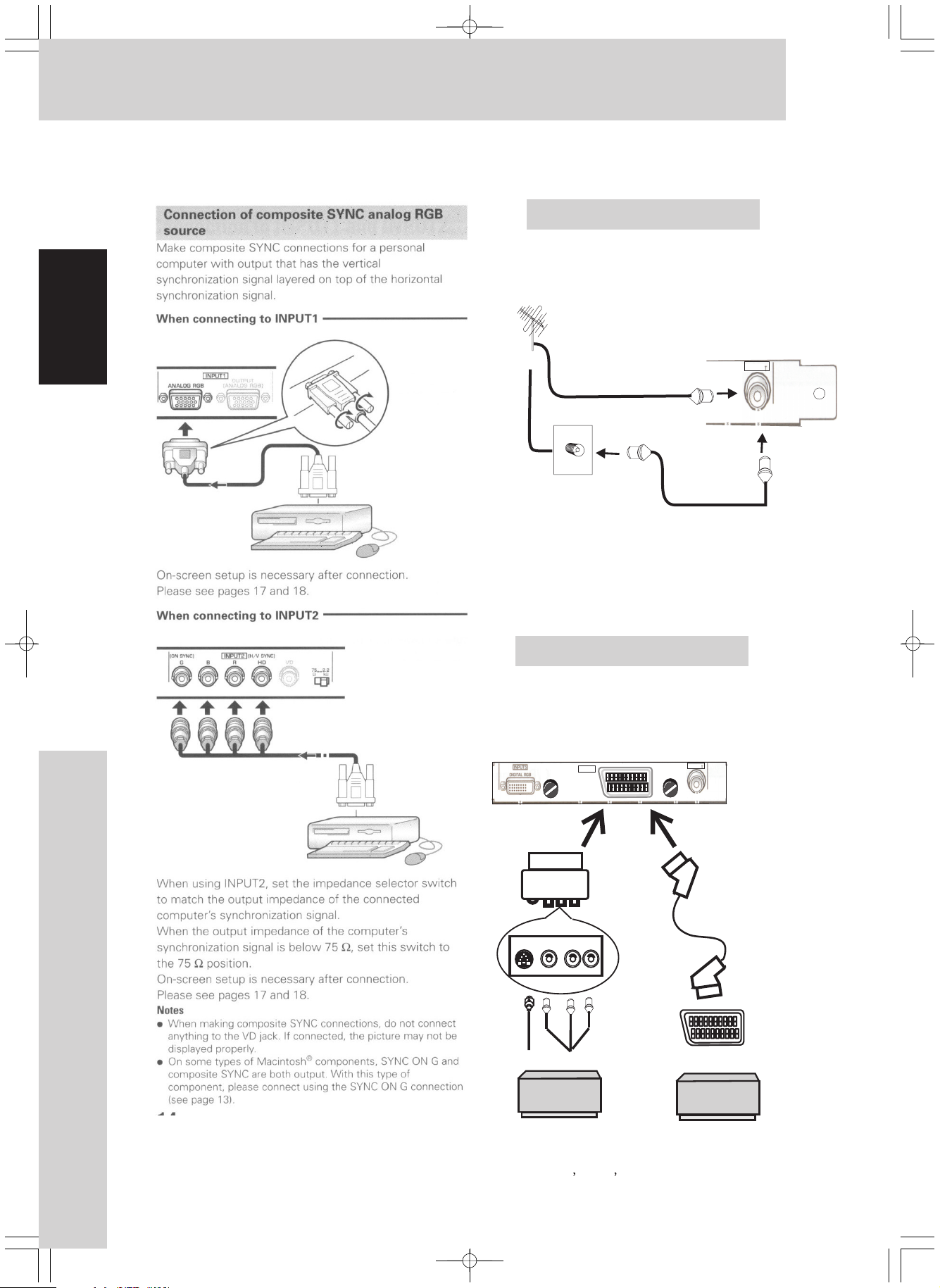
Input Connection
Connection to INPUT 3
Connect the Antenna:
English
Or
Antenna Cable
Antenna Cable
Note : Signal of input 3 jacks are all
compatible with the following TV system
:PAL BG / DK/ I and SECAM .
Connection to INPUT 4
Connect the SCART: Connect an AV
component that has S-Video, Video
output jack to the video card`s input 4.
INPUT4
SCART
AVIOSYS DTV 6010
INPUT3
TV
INPUT3
TV
Input Connection
SCART to AV
10
Or SCART to SCART
S-Video Video Audio L-R
AV Component
AV Component
Note : Signal of Input 4 jacks are all
compatible with the following TV system
:NTSC PAL SECAM and 4.43NTSC.
Page 12

Connection to INPUT 5
A computer equipped with DVI
( Digital RGB signal) can be
connected to the video card`s
DVI connector.
Input Connection
English
In the case of Input5 the DVI-I connector
will only accept digital information. (The
analogue portion of the connector is not
connected)
11
Input Connection
Page 13

Remote Control Function
English
AVIOSYS
Inserting Batteries
Before using the Remote Controller,
insert the supplied two batteries.
1)
While pressing the Stopper,
pull out the Battery Holder.
2)
Insert two batteries.
3)
Insert the Batteries Holder into
the Remote Controller.
If the Remote Controller fails to operate correctly
, it may require new batteries. Replace them with
new R03 AAA .1.5V batteries(A battery is normally
expected to last about 1 year. However, it depends
on operation frequency.)
Make Sure to match the terminals correctly when
inserting the batteries.
CAUTION
Danger of explosion if battery is incorrectly
replaced. Replace only. With the same or
equivalent type recommended by the equipment
manufacture. This card used batteries according
to manufacturer's instructions.
WARNING
Risk of fire, explosion and burns. Do not recharge,
disassemble, heat above 100C or incinerate.
Keep the batteries out of the reach of children.
Never put batteries in mouth.
If swallowed ,call your doctor right away.
Please do not dispose of
batteries in normal waste
disposal.
Bij dit product zijn batterijen
NL
geleverd. Wan neer deze leeg
zijn, moet u ze niet weggooien
maar inleveren als KCA.
Remote Controller
Most of the DTV6010 functions will
not operate without the use of this controller
Remote Controller Buttons
The following buttons also exist
on the Plasma remote controller.
1) POWER
2) SCREEN SIZE
3) AUTO SETUP
4) MUTE
5) POINT ZOOM
6) PC1(Input1-RGBD-Sub)
7) PC2 (Input2-RGBBNC)
8) DISPLAY
9) TV (Input 3- )
10) SCART(Input4-VIDEO)
11) DVI (Input 5- Digital RGB)
12) PLASMA MENU
13) CH+ /
14) CH -- /
15) VOL+
16) VOL-
17)
18)
19) SET
20)~ 30) 0~9,
The following are TV MENU & PIP Fast Buttons
of DTV6010.
31) TV MENU
32) ON/OFF( Page 13)
33) SWAP( Page 14)
34) MOVE( Page 15)
35) TYPE( Page 13)
36) AUDIO
The following are Teletext Buttons of DTV6010.
37) CLOCK
38) TV/ TEXT MIX
39) LIST
40) HOLD
41) REVEAL
42) INDEX
43) EXPAND
Picture format : 4:3 , Wide, Full , Zoom
44)
45) ~ 48) RED, GREEN, YELLOW, BLUE
Using the Remote Controller
Direct the Remote Controller to the
Remote Control Sensor and press an
appropriate button.Distance from the
DTV6010: Within approximately 5 metres
Angle: Within approximately 15 degrees in the
vertical and horizontal directions from the
central axis
Remote Control Function
12
Page 14

Watching TV
Watching TV
This section explains functions and operations
used in watching TV..
TV Fast Key & Functions
1. To turn on the PDP, Press
2. To select the TV Mode,
press in Plasma area.
3. To select the TV program,
press the numeric buttons or button.
4. To adjust the volume, press .
5. To mute the sound, press
6. To pause the screen :
Press Button in TELETEXT area.
The main screen will freeze and then press
HOLD
7. Additional Functions:
Display Current Information
Press button
I
t will show Channel number, TV system,
Audio format of local TV station ,
screen size and so on for 6 seconds.
TV
HOLD
button again to return to TV mode..
DISPLAY
Ch23
PALBG
NICAM
EXPEND
WSSOFF
POWER
0~9 CH+/-
VOL +/-
MUTE.
Ch23
PAL BG
NICAM
FULL
1280*720P
Advanced Operation
PIP mode.
To display the PIP screen
P
ress button in PIP area of
ON /OFF
remote controller. Press button
again to cancel PIP mode
Switch round PIP Modes
TYPEPress Button.
With each press of the button , the Current
PIP Mode will switch a round
One/ PAP/ Tile0/16 / Tile1/12 Mode.
A
5
Press
ON/OFF
Press
TYPE
ON /OFF
A
5
English
Change Main-Picture Format
Press Button.
With each press of the button,
Main-Picture format switches between
4:3,WIDE,FULLand ZOOM.
4:3
A
ZOOM
WIDE
FULL
A
Change Audio Format
Audio
Press Button
It will show the audio format local TV system
( A2/ NICAM ), press AUDIO you can change
the support audio format (MONO/ STEREO/ DUAL).
1. If channel station only support MONO
Mono NO Stereo
2. If channel support STEREO :
AUDIO LEFT RIGHT STEREO
A
Note : PIP function only work in TV and
SCART mode.
3. IF channel support DUAL language
AUDIO DUAL- A DUAL - B
13
Watching TV
Page 15

Watching TV
Set Main Source
1.Press button to set to TV, press button
2. Press button will exchange Main Source
English
Move Sub-Picture
1. Press Button.
2. Press / / / to move Sub-Picture.
3. Press to fix the Sub-Picture position.
TV SCART
tosettoSCART.
SWAP
between TV and SCART. Audio is output
for main channel
TV
MOVE
A red frame around Sub-Picture and OSD prompt appears.
Sub-Picture will move to one of the 9 positions on screen.
MOVE
SCART
Press
SCART
Press
TV
SCART
TV
Swap Main source with Sub-Picture
Press Button.
Fade in / out Sub-Picture
1. Press Button.
2. Press / to fade in/out Sub-Picture.
3. Press Button to Exit.
SWAP
Press
SWAP
A
A red frame around Sub-Picture and OSD prompt
appears.
The red frame and OSD prompt disappears.
Press
SET
5
SET
SET
Press
5
A
TV
E
Press
MOVE
TV
Press
12
4
78
5
Press
MOVE
E
E
5
Freeze the MAIN screen
Press Button in TELETEXT area.
3
6
The main screen will freeze and then press
HOLD
operation.
HOLD
button again to resume normal
5
9
Watching TV
14
Page 16

Watching TV
TILE 12 Mode Main Picture and 12 Sub -Pictures
Display the TILE 12 screen:
Press n PIP section
On/Off i
and then to select Tile12 , if MAIN is set to TV.
TYPE
The Sub-pictures will display the input from
SCART with a strobing effect.
MAIN
Set Main Source / SWAP Function
Press button to set to TV, press button
1.
Scart
Scart
Scart
Scart
When SCART is main picture the sub-picture became
a channel browser.
TV SCART
tosettoSCART.
Or Press button to set between TV
SWAP
and SCART.
Scart Scart Scart
Scart
TV
Scart
Scart
ScartScart
SCART
CH 1 CH 2 CH 3
Press
CH 12
CH 11
Press
TV
CH 10
SCART
CH 8
CH 4
CH 5
CH 6
CH 7CH 9
Page Down Sub -Pictures
1
Press button
MOVE
A red frame appears around the last
Sub-Picture.
2
Press button once again.
MOVE
All Sub-Pictures is paged down, and the red
frame disappears.
Display Continuous Pictures for
Selected Sub-Picture.
1 Select a desired Sub-Picture.
The Selected Sub-Picture is active and
around with a red frame
2
Press Button
SWAP
The continuous frames of Selected
Sub-Picture display on all Sub-Pictures.
1
12
11
10
14
14
14
23
SCART
8
9
1414
14
SCART
14
14
14
14
14
14
4
Press
MOVE
5
6
7
Press
SWAP
13 14 15
24
SCART
23
22
21
20
Press AND THENMOVE
13 14 15
24
SCART
23
22
21
20
English
16
17
18
19
16
17
18
19
Select a Sub -Picture
1.
MOVE
Press button.
A red frame appears around the active Sub-Picture.
2. Press / / / .
Each time a different Sub-Picture is selected,
it become active, the previous Sub-Picture
then ceases to be active
To convert a the selected Sub-Picture Screen
to FULL Screen
SET
Press button
The Selected Sub-Picture displays on full screen.
CH 1 CH 2 CH 3
CH 12
SCART
CH 11
CH 10
CH 8
CH 3
CH 4
CH 5
CH 6
CH 7CH 9
Press
MOVE
Press
SET
CH 12
CH 11
CH 10
CH 12
CH 1 CH 2 CH 3
SCART
CH 8
Press
CH 1 CH 2 CH 3
SCART
CH 11
CH 10
CH 8
CH 4
CH 5
CH 6
CH 7CH 9
CH 4
CH 5
CH 6
CH 7CH 9
FREEZE the MAIN screen
Press Button in TELETEXT area.
HOLD
The main screen will freeze and then press
HOLD
button again to resume
normal operation..
15
Watching TV
Page 17

Watching TV
TILE 16 Mode TV WALL with 16 screens
Display the TILE 16 screen: Press in
PIP section and then to select Tile16
TYPE
English
Page Down Sub -Pictures
1
Press button
A red frame appears around the last Sub-Picture.
2
Press button once again.
Channel1-16 is paged down to next 16 channel
(17-33, 24-40 and so on ),
and the red frame disappears.
If the channel arrives to the max, the rest of the
Sub-Pictures will be greyed out.
MOVE
MOVE
On/Off
Select a Sub -Picture
1. Press button.
A red frame appears around the active
Sub-Picture.
2. Press / / / .
With each press of the button, the Selected
screen becomes active, the red frame moving
around it, and the previous active screen is no
longer active.
To convert the Selected Sub-Picture
to Full Screen
Press button
The Selected Sub-Picture displays on full screen.
MOVE
SET
Press
MOVE
Press
4
8
12
16
12
4
8
Press
MOVE
SWAP
Press
SWAP
1
5
9
10
14
13
If the input is selected for SCART the tile 16 mode
has a continuos strobing effect.
Swap video source in TILE 16
Press utton.
With each press of the button, the TV swaps
input source with SCART. It will keep auto-scanning
all the 16 screens ,
SWAP
1
5
9
10
3
2
67
11
15
B
3
2
67
11
17
21
25
29
S
S
S
18
22
26
30
19
23 24
27
31
S
S
S
S
S
S
20
28
32
S
S
S
CH 3
Press
SET
CH 3
Watching TV
13
14
15
16
S
S
S
S
16
Page 18

TELETEXT Function
1 Text Mode
Page
Page
TELETEXT MODE
All the Text Buttons available in Text Mode.
Switch among TV/TEXT Modes
Press Button
With each press of TV / TEXT Button,
System switch between TV Mode, TEXT Mode,
MIX Mode, PAP Mode.
Display Index Page
Press Button
With each press of button, System search
for the index page if the index link is valid, or this
operation will be ignored.
Display Text Page
1 Press Button
2 Press three Numeric Buttons
3 Press FastKey Button
TV/TEXT
INDEX
INDEX
Text
Change to Text Mode if not in Text Mode
Displays the Text Page the three Numeric Button re
presents if the page is available, or this operation
will be ignored.
// /
Red Green Yellow Blue
Link the Text Page which the Corresponding Button.
English
TV
Hold On/ Off Current Page
Press the Button if the page is not held, it will become
held thus preventing it from being updated, a Hold Prompt
will be displayed in header status row.
If the page is currently held, the hold will be removed thus
allowing the page to update.
REVEAL Concealed Characters
Press Reveal Button
Toggle state of concealed characters between visible and invisible.
If reveal is turned on, any characters that are normally concealed
will be displayed for 6 seconds.
Hold
17
TELETEXT Function
Page 19

TELETEXT Function
6 List Mode
Page Page(searching) Date Time
English
Page Page(searching) Date Time
L
Page
List Mode On/ Off
Press ButtonList
Allows the programming of the Fast key buttons to users
choice of pages
Toggles the system into and out of list mode.
A list prompt character " appears in the lower status row.
On setting list mode, the current list is read from system( defaults
to Pages 100,101,102 and 899), each page number is assigned to
a colour, in the order Red, Green, Yellow and Cyan. The Red page
is requested as the display page and the other colour pages are
requested in the background.
Display Subtitle Text Page
Available in Text Mode.
Press Button
When pressed , the system searches for and display, if found,
the next subtitle page.
Expand the Current Page
Press Button
With each pressing, the Current Page toggles between normal
page, enlarged top half of current selection and enlarged bottom
half of current selection is displayed
Sub titles
L"
with normal=>large top => large bottom => normal size.
Large Top: the top half of current text page is displayed on full screen,
Large Bottom: the lower half of the current text page is displayed on
full screen.
CLOCK
Available if there is teletext information.
Press Button.
When press, the current time will be displayed on the top right
hand corner of th e screen as Hour Minute and Seconds for 6
seconds.
Clock
TELETEXT Function
18
Page 20

TV Menu
ListofTVMenu
The figures on the illustrated Menu are for
explanation purposes only, and they may be
different from the actual Menus.
MAIN Sub-Menu
1) Adjusting Main-Picture Settings.
2) Adjusting Main-Picture Scale.
3) Setting Main-Picture FILM MODE.
4) Setting Main-Picture Noise Mode.
PIP Sub-Menu
5) PIP Mode Set MAIN PIP
6) Adjusting Sub-Picture Settings
7) Adjusting Sub-Picture Position.
8) Adjusting Sub-Picture Blending.
9) Adjusting Sub-Picture Size.
10 ) Sub-Picture Aspect Set.
TV Sub-Menu
11)TVChannelSet.
12) Channel Name Edit.
13) Channel Swap.
14) Manual Tuning.
15) Fast Autotuning
16) Channel Add.
17) Channel Del.
English
SETUP Sub-Menu
18) Resolution set
19) Format Set.
20) Country Set
21) OSD language set
22) SCART Colour Set
23) SCART In Set
24) GAMMA
25) Reset
MISC Sub-Menu
26) DEMO
27) Display Firmware version
19
TV Menu
Page 21

TV Menu
1 Press TV Menu to display the menu screen
English
2 Press / to select PIP / TV / SETUP /MISC.
.
Main-Picture
Adjusting Main-Picture Parameters
1. Select the correlative items.
The correlative items which include CONTRAST,
BRIGHTNESS, TINT, COLOUR and SHARPNESS
can be adjusted to get better effects.
The CONTRAST item turns to Selected Mode.
2. Press button to turn on Set Mode.
The CONTRAST item is highlighted.
NOTE: All the item can be changed and set only in
Set Mode.
3. Press the / to adjust.
4. Press button to turn off Set Mode.
5. Press / Button to select other correlative
items.
SET
SET
3 Press / to select the item to be adjusted
4 Press ENTER to display the adjustment
screen for the select item
.
.
5 Press / to adjust the value
TV Menu
.
20
Page 22

TV Menu
Adjusting Main-Picture Scale
1. Select the item.
The item turns to Selected Mode.
Press button to turn on Set Mode.
2.
The H SCALE item turns to Set Mode.
NOTE: All items can be changed and set only in
Set Mode.
Press the / Button to adjust to a desired
3.
Horizontal Scale. With each press of the button
, the Main- Picture is set to the corresponding
H Scale.
Press button to turn off Set Mode.
4.
Press / Button to select V SCALE item and
5.
adjust Vertical Scale.
Setting Main-Picture Film Mode
Select the MODE item.
1.
The FILM MODE item turns to Selected Mode.
Press button to turn on Set Mode.
2.
The FILM MODE item turns to Set Mode.
NOTE: All the items can be changed and set only
H SCALE
H SCALE
SET
Set
FILM
SET
in Selected Mode.
English
Press the / Button to select new FILM Mode.
3.
The FILM MODE item include FULLY AUTO,
AUTO SM/VT, AUTO AFM/VT, AUTO GFX/VT/SM,
VT, AFM, SM, GFX. With the pressing, System
changes to the new FILM MODE.
The Film Mode include: VT(Vertical Temporal Film Mode),
AFM(Adaptive Film Mode), SM(Static Mesh Film Mode),
GFX Film Mode.
FULLY AUTO: it can be any Film Mode.
AUTO SM/VT: VT, AFM Film Mode not allowed.
AUTO AFM/VT: SM, VT Film Mode not allowed.
AUTO GFX/VT/SM: AFM Film Mode not allowed.
VT: VT Film Mode only.
AFM: AFM Film Mode only.
SM: SM Film Mode only.
GFX: GFX Film Mode only.
Press SET Button to turn off Set Mode.
4.
With each press, System is set to the new
FILM MOD E and no cancel operation can
be done.
Setting Main-Picture Noise Filter
1. Select the NOISE item.
The NOISE FILTER item turns to Selected Mode.
2. Press SET button to turn on Set Mode.
The NOISE FILTER item turns to Set Mode.
3. Press the / Button to change to new
Noise Filter. The Noise Filter include:
OFF, SP(Spatial Noise Reduction Filter),
TMP1(Temporal Noise Reduction Filter ),
TMP2 (Temporal Noise Reduction Filter),
TMP3 (Temporal Noise Reduction Filter),
3D1(Spatial and Temporal Noise Reduction Filter ),
3D2(Spatial and Temporal Noise Reduction Filter ),
3D3(Spatial and Temporal Noise Reduction Filter ).
4 Press Button to turn off Set Mode.
With each press, system is set to the corresponding
SET
Noise Mode, and no cancel operation can be done.
21
TV Menu
Page 23

TV Menu
English
PIP(Sub-Picture)
Setting PIP( Sub-Picture ) Mode
1.
Select MODE item.
The PIP MODE item turns to Selected Mode.
2.
Press button to turn on Set Mode.
The PIP MODE item turns to Set Mode.
3.
Press the / Button to select new PIP MODE.
With each press of the button ,system changes to the
newPIPMODEandthe" "turnto" ".
4.
Press the Button to turn off Set Mode.
With each press of button, the new
PIP MODE is set and system memorizes it.
PIP
SET
ONE PAP
SET
SET
Press
A
Press
A
Press
A
Press
Press
Adjusting PIP Parameters
1. Select the correlative items.
The correlative items including
TINT, COLOUR SHARPNESS
better effects.
The item turns to Selected Mode.
CONTRAST
2. Press button to turn on Set Mode.
The item turns to Set Mode.
SET
CONTRAST
and can be adjusted to get
CONTRAST, BRIGHTNESS,
A
5
5
TV Menu
NOTE. All the items can be changed and set only
in Set Mode.
3. Press the / Button to get a better effect.
4. Press Set Button to turn on Set Mode.
5. Press / Button to select and adjust the other
correlative items.
22
Page 24

TV Menu
Adjusting Sub-Picture Position
It will gently adjust the sub-picture to any position on screen.
Only available in ONE PIP Mode.
1 Select the Horizontal Position item.
The Horizontal Position item turns to Selected Mode.
The correlative items includes H POSITION
and V POSITION
2 Press button to turn on Set Mode.
The Horizontal Position item turns to Set Mode.
3 Press the button to adjust Horizontal position.
With each press of the / Button, the Sub-Picture
moves to a new Horizontal Position.
4 Press button to turn off Set Mode.
5 Press / button to select V POSITION item and
adjust the Vertical Position of the Sub-Picture.
SET
/
SET
Horiziontal Position Adjust
Press
English
5
Vertical Position Adjust
Press
5
5
Adjusting Sub-Picture Blend
Fade in/ out Sub-Picture,
available only in .
Select PIP- Blending item.
1.
The PIP-BLEND item turns to Selected Mode.
Press button to turn to Set Mode.
2.
The PIP-BLEND item turns to Set Mode.
3. Press the / Button to adjust.
With each press
and the Sub-Picture is faded in/out.
Press button to turn to Set Mode.
4.
Press and / Button Close MENU.
5.
The OSD will time-out after 30 seconds if no
SET
SET
TV MENU
available button pressed.
ONE PIP Mode
, the bar changes,
Press
5
23
5
5
TV Menu
Page 25

TV Menu
English
Adjusting PIP - Size
Only available in .
Select PIP- SIZE item.
1.
The PIP-SIZE item turns to Select Mode.
Press to turn on Set Mode.
2.
The PIP-SIZE item turns to Set Mode.
Press / to adjust Sub-Picture size.
3.
With each press of
and the Sub-Picture is zoomed in/ out.
Press to turn off Set Mode.
4.
Press to Close TV MENU OSD.
5.
The TV MENU OSD will time-out after 30 seconds
if no available button pressed.
SET
SET
TV MENU
ONE PIP Mode
/ , the bar changes,
Press
5
Set Sub-Picture FORMAT
Only available in .
Select FORMAT item.
1.
The FORMAT item turns to Selected Mode.
Press to turn on Set Mode.
2.
The FORMAT item turns to Set Mode.
Press / to adjust.
3.
There are 4:3 mode and 16:9 mode available.
Press to turn off Set Mode.
4.
CloseTVMENUOSD.
5.
NOTE: The TV MENU OSD will time-out after 30
seconds if no available button is pressed.
SET
SET
ONE PIP Mode
Press
5
TV Menu
24
5
5
Page 26

TV Menu
TV
Preset Channel
1. Select PRESET CHANNEL item.
The PRESET CHANNEL item turns to Selected Mode.
2. Press to turn on Set Mode.SET
The PRESET CHANNEL item turns to Set Mode.
3. Press / or two numeric buttons to select new
channel. E.G. for number 5 enter 05.
The corresponding new channel displays.
It will do nothing when only 1 numeric button pressed.
If unavailable two-digit channel is pressed, it will change
to the max channel.
If three or more numeric buttons are pressed, it will
change to the channel which the first two buttons represent.
4. Press to turn off Set Mode.SET
5. Press to Close TV MENU OSD.TV MENU
The TV MENU OSD will time-out after 30 seconds if no
available buttons pressed.
English
Channel Name Edit
1. Press Button to ensure editing.SET
The Channel item turns to Set Mode.
2. Press the / Button to select the first character
for the channel.
The channel name is composed of 8 character,
and each bit can be 0~9,A~Z,+, - or ' '.
3. Press Button to select and edit others./
4. Press Button to Set.SET
5. CloseTVMENUOSD.
The TV MENU OSD time-out after 30 seconds if no
available button are pressed.
Ch20
CCTV++04
25
TV Menu
Page 27

TV Menu
English
Channel Swap
To swap the current TV Channel with the selected channel.
For example, suppose the current channel is 33.
1. Select SWAP item.
2. Press Button to ensure swapping.SET
3. Press the / / 0~9 Button to select the channel
to swapped with.
The selected channel numb pears.er 6 ap
4. Press to swap.SET
The Current CH33 displays the Picture of original
CH6 now.
5. Close TV MENU OSD.
The TV MENU OSD time-out after 30 seconds if no
available button are pressed.
Manual Tuning
1. Select the MANUAL TUNING item.
2. Press Button to ensure manual tuning.Set
3. With each press of / , the frequency increase /
decrease 62.5KHz. With each pressing of / ,
the frequency increase/ decrease 0.1MHz.
4. For specified frequency, press numeric button.
Press 3 numeric button, or press 2 numeric button
and then SET button, the picture of the specified
frequency will be shown if available, or the screen
will be black.
Fast AutoTuning
1. Select FAST AUTO TUNING item.
2. Press ButtonSet
appears."Yes?"
If you want cancel auto tuning, press button.TV MENU
3. Press Button.SET
With each press, the System begins scanning.
All available channels will be stored in memory
Add New Channel
1. Select ADD NEW CHANNEL item.
2. Press to ensure copying.SET
A new channel the same as the Current Channel will
be copied and added to the end.
Delete Channel
1. Select DELETE CHANNEL item.
2. Press button to del the Current Channel.SET
TV Menu
26
Page 28

TV Menu
SETUP
Resolution Set
To set the video resolution
1. Select item.
2. Press to turn on Set Mode.
3. Press / to select a desired Timing Mode.
The Timing include: 1280 * 720P, 1920 * 1080i.
4. Press button to set to the new Timing Mode.
Pictures display in new Timing Mode, and Set
Mode closed.
For mat Set
To set different size of video screen.
1. Select item.
2. Press Button to turn on Set Mode.
3. Press / Button to select a desired Format.
4. Press Button to Set to the selected colour Space.
It includes : to match the
transmitted signal
RESOLUTION
SET
SET
Format
SET
SET
4:3,WIDE,FULL,ZOOM
English
Country Set
Supports Pan European TV system of 29 Countries
1 .Select COUNTRY item.
2. Press Button to turn on Set Mode.
3. Press / Button to select a desired Country.
The country include: POLAND PAL D/K, ROMANIA PAL G,
U.K. PAL I, FRANCE SECAM L, GERMANY PAL B/G,
ITALY PAL B/G, SWEDEN PAL B/G, SPAIN PAL B/G,
BELGIUM PAL B/G, PORTUGAL PAL B/G,
NORWAY PAL B/G, IRELAND PAL I, NETH PAL B/G,
DENMARK PAL B/G, CYPRUS PAL B/G, ALBANIA PAL B/G,
YUGOSLAV PAL B/G, MONACO SECAM L ,
BUKG SECAMD/K, TURKEY PAL B/K,CZECH SECAM D/K,
AUSTRIA PAL B/G, HUNG SECAM D/K, ICELAND PAL B,
GREECE SECAM B/G, RUSSIA SECAM D/K.
4. Press Button to set .
On Screen Language Display
1. Select item.
2. Press to turn on Set Mode.
3. Press / select one language in OSD.
OSD language include :ENGLISH, DEUTSCH,
FRANQUAIS, ITALIA, ESPANOL, HOLLAND
SVENSKA, PORTUGUES, SUOMI, TURKQUE
4. Press Button to set to.
The OSD displays in the corresponding language.
SET
SWITZER PAL B/G, LUX PAL B/G, FINLAND PAL B/G,
SET
Language
SET
SET
SCART Colour Set
Supports all the video formats throughout the world
1 Select SCART Colour item.
2 Press to turn on Set Mode.
3 Press / to select SCART Colour Mode .
SCART tColour Mode include:
Auto, PAL, NTSC, SECAM
4 Press Button to set to.
SET
SET
27
TV Menu
Page 29

TV Menu
SCARTINSet
Set Main Picture SCART Input Source for SCART
Button on remote controller. When SCART Button
pressed, the Main Picture will change to the SCART
IN Source.
English
1. Select IN item.
2. Press SET to turn on Set Mode.
3. Press / to switch between :
Auto, Video, S Video, RGB.
If set to Auto Mode, System will auto detect Video or
S Video input source for Main Picture.
4. Press Button to set to.
NOTE : If set to AutoMode, the system will not
switch to RGB
GAMMA Adjust
Adjust the gamma setting to your preference. This
setting will effect the dark areas of the image, with
the higher number giving darker levels.
1. Select GAMMA item.
2. Press to turn on Set Mode.
3. Press / to adjust.
When the value is 1.0, there is no Gamma effect.
4 Press SET Button to set to.
SCART
SET
SET
Reset
1. Select Reset item.
2. Press to turn on Set Mode.
" Yes ?" appears.
Press button or / to cancel.
3. Press Button.
System reset to default states.
SET
TV MENU
Set
MISC
DEMO
Auto Demonstrations all the OSD functions.
TV Menu
28
Page 30

ADDITIONAL INFORMATION
TROUBLESHOOTING
If you are having trouble with the TV card, check the following items to see if the
problem can be resolved. Sometimes another device may be at fault, so be sure to also
inspect the other devices being used. If the trouble cannot be resolved, contact your
nearest PIONEER authorised service centre or your supplying dealer.
Problem Possible Solution
Cannot switch to inputs 3-5 TV card is not inserted correctly, ensure card is
correctly inserted .
Remote control unit does not operate Are batteries inserted with correct polarity.
Are batteries worn out (Replace with new
batteries)
Are you using it under strong fluorescent
lighting?
Is a fluorescent light illuminating the remote
control sensor?
No Pictures Is connection to other components correct? (See
pages 8-11)
Has set-up been done correctly after connection?
(see page 27)
Is the correct input selected?
Is a non-compatible signal being connected?
Is picture adjustment correct? (See pages 20-21)
Please remove the TV Card from the Plasma,
if normal operation and picture on inputs 1 and 2
are restored the TV Card has a malfunction.
Unit cannot be operated External influences such as lightning, static
electricity ,etc, may cause improper operation.
In this case turn off the power for 1-2 minutes
and try again.
English
Please remove the TV Card from the Plasma,
if normal operation and picture on inputs 1 and 2
are restored the TV Card has a malfunction.
Picture is cut off Are settings for picture format correctly set.
(See page13)
Green Pictures Ensure Slot interface setting is set to
COMPONENT1(refer to page7 'setting integrator
menu')
An outline of previous still images After displaying a PC image or any other still
can be seen on the screen even image, it is recommended to view a normal moving
when a different input is selected
picture in the 'Wide' or 'Full' screen setting for more
than 3 times the length of the previous still image.
29
ADDITIONAL INFORMATION
Page 31

ADDITIONAL INFORMATION
Aviosys DTV6010 Expansion Card Specifications
Features
PAL / SECAM TV Tuner
NICAM / IGR Stereo
SCART Input with RGB, Y/C and Composite Video
DVI-D Input
Video + Tuner Picture in Picture modes
Full remote control including Plasma functions
Teletext (FASTEXT) and TOP
English
General Specifications
Brand Name Aviosys (Aviosys International Inc.)
Country European
Receiving Broadcast Standard B/G, I, D/K, L
Colour System PAL/SECAM (NTSC AV Input)
Sound System NICAM (Digital Stereo) / IGR (German Stereo)
Receiving Channel frequency 41.25MHz to 870.25MHz
Tuning System Fast Auto Tuning system
Manual Tuning system (with scanning, fine tuning and
direct frequency tuning)
Manual Channel Sorting, with channel add and delete.
Manual Channel Name Editing
Noise Reduction Main Channel 3D Noise Reduction (sp. Tmp1, tmp2,
tmp3, 3d1, 3d2, 3d3)
Film Conversion Inverse 3:2 / 2:2 Pull down
Output Scaling By Menu Adjust 1280 X 720P (default), 1920 X 1080i
Picture Format Manually switchable (wide, full, 4:3, zoom)
Main Picture Features Horizontal and Vertical size adjustment
Horizontal and Vertical Sharpness
Teletext FLOF / LIST / TOP
Subtitle and clock feature
Picture In Picture PiP Mode 1 Moveable (9 positions + Fine Movement)
Dimensions
W 243.8mm
H 136.9mm
D 27.6mm
Weight 0.3 Kg
ADDITIONAL INFORMATION
Resizeable (multiple levels)
Alpha Blending
PaP Mode 2 TV + TEXT
TV+SCART
Audio swapping feature
TILE 16 Mode 3 16 images, selected one live (Image strobe on AV,
channel browser on TV)
TILE Main + 12 Mode 4 Main image (centre) + 12
Swapping feature
30
Page 32

ADDITIONAL INFORMATION
Material Construction Mild Steel Frame
Safety Standard CE
RFI EN55013:1990+A12:1994+A13:1996+A14:1999
EN61000-3-2:1995 Class D+A14:2000
EN61000-3-3:1995+A1:2001 Emission standard
Limits for harmonic current emission
Immunity EN55020:1994+A11:1996+A12:1999+A13:1999+A14:1999
Limitation of voltage fluctuation and flicker in low voltage
supply system
EN61000-4-2:1995, EN61000-4-3:1995, EN61000-4-4:1995
LVD IEC60065:1998, 10.1
Tuner Phillips FQ1216ME
Connectors Antenna Jack X 1
SCART
DVI-D
Accessories Remote Control Unit
2 X AAA Batteries
Operation Manual
Connection Sticker
2 X Screws for installation
OSD 10 Language English, French, German, Italian, Finnish,
Portugese, Spanish, Turkish, Dutch, Swedish
Immunity standard
English
Engineering Specifications
Operating Temperature Range 15 -70
Operating Humidity Range MAX 85%
Storage Temperature Range 0 -70
Storage Humidity Range MAX 85%
Power 12V
Power Consumption 9W Nominal
Current maximums
+13.5V100mA
+12V800mA
Antenna Input Impedance 75 Ohms
DVI-D Input Resolution Compatibility ( INPUT 5 )
Resolution Refresh Rate Screen Size Remarks
(Dot X Line) Vertical Horizontal DOT by DOT 4:3 FULL PARTIAL
640 X 480 60Hz 31.5KHz 640 X 480 1024 X 768 1280 X 768
800 X 600 56Hz 35.1KHz 800 X 600 1024 X 768 1280 X 768
60Hz 37.9KHz
852 X 480 60Hz 31.7KHz 852 X 480 1280 X 768
1024 X 768 60Hz 48.4KHz 1024 X 768 1280 X 768
1152 X 864 60Hz 53.7KHz 1024 X 768 1280 X 768
1280 X 768 56Hz 45.1KHz 1280 X 768
60Hz 48.4KHz
1280 X 960 60Hz 60.0KHz 1024 X 768 1280 X 768
1280 X 1024 60Hz 64.0KHz 960 X 768 1280 X 768 1280 X 768
Optimal Display Expanded (Some fine detail is difficult to see)
Simple Reproduction (No fine details reproduced) Not Available
31
ADDITIONAL INFORMATION
Page 33

English
Page 34

< PEE-018 >
Aviosys International Inc.
9F,No.101 Pan-Hsin Road.Pan-Chiao 220, Taipei, Taiwan
Tel : 886-2-2959-2092 Fax: 886-2-2959-2091
.
 Loading...