

PIONEER DEH-MG2037, DEH-MG2137 Service Manual
PIONEER CORPORATION 4-1, Meguro 1-Chome, Meguro-ku, Tokyo 153-8654, Japan
PIONEER ELECTRONICS (USA) INC. P.O.Box 1760, Long Beach, CA 90801-1760 U.S.A.
PIONEER EUROPE NV Haven 1087 Keetberglaan 1, 9120 Melsele, Belgium
PIONEER ELECTRONICS ASIACENTRE PTE.LTD. 253 Alexandra Road, #04-01, Singapore 159936
C PIONEER CORPORATION 2003
K-ZZD. JUNE 2003 Printed in Japan
ORDER NO.
CRT3091
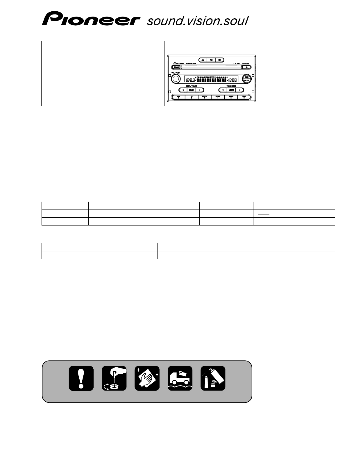
CD/MP3 6 DISC IN-DASH CHANGER WITH FM/AM TUNER
DEH-MG2037ZFXU/UC
FORD
DEH-MG2037ZF/XU/UC
VEHICLE DESTINATION PRODUCED AFTER FORD PART No. ID No. PIONEER MODEL No.
Ranger U.S.A., CANADA August 2003 4L5T-18C815- DEH-MG2037ZF/XU/UC
Ranger U.S.A., CANADA August 2003 4L5T-18C815- DEH-MG2137ZF/XU/UC
- This service manual should be used together with the following manual(s):
Model No. Order No. Mech. Module Remarks
CX-951 CRT2872 G2 CD Mech. Module:Circuit Description, Mech.Description, Disassembly
For details, refer to "Important symbols for good services".
DEH-MG2137ZFXU/UC
2
1
234
12
34
F
E
D
C
B
A
DEH-MG2037ZF/XU/UC
SAFETY INFORMATION
-
CD section precaution
1. Before disassembling the unit, be sure to turn off the
power. Unplugging and plugging the connectors during power-on mode may damage the ICs inside the
unit.
2. To protect the pickup unit from electrostatic discharge during servicing, take an appropriate treatment (shorting-solder) by referring to “the DISASSEMBLY” on page 69.
3. After replacing the pickup unit, be sure to check the
grating. (See p.63.)
This service manual is intended for qualified service technicians; it is not meant for the casual do-it-yourselfer.
Qualified technicians have the necessary test equipment and tools, and have been trained to properly and safely repair
complex products such as those covered by this manual.
Improperly performed repairs can adversely affect the safety and reliability of the product and may void the warranty.
If you are not qualified to perform the repair of this product properly and safely, you should not risk trying to do so
and refer the repair to a qualified service technician.
[ Important symbols for good services ]
In this manual, the symbols shown-below indicate that adjustments, settings or cleaning should be made securely.
When you find the procedures bearing any of the symbols, be sure to fulfill them:
2. Adjustments
To keep the original performances of the product, optimum adjustments or specification confirmation is indispensable.
In accordance with the procedures or instructions described in this manual, adjustments should be performed.
3. Cleaning
For optical pickups, tape-deck heads, lenses and mirrors used in projection monitors, and other parts requiring cleaning,
proper cleaning should be performed to restore their performances.
5. Lubricants, glues, and replacement parts
Appropriately applying grease or glue can maintain the product performances. But improper lubrication or applying
glue may lead to failures or troubles in the product. By following the instructions in this manual, be sure to apply the
prescribed grease or glue to proper portions by the appropriate amount.For replacement parts or tools, the prescribed
ones should be used.
4. Shipping mode and shipping screws
To protect the product from damages or failures that may be caused during transit, the shipping mode should be set or
the shipping screws should be installed before shipping out in accordance with this manual, if necessary.
1. Product safety
You should conform to the regulations governing the product (safety, radio and noise, and other regulations), and
should keep the safety during servicing by following the safety instructions described in this manual.

3
5
6
7
8
F
E
D
C
B
A
5
6
7
8
DEH-MG2037ZF/XU/UC
CONTENTS
SAFETY INFORMATION......................................................................................................................................................2
1. SPECIFICATIONS.................................................................................................................................................................4
2. EXPLODED VIEWS AND PARTS LIST ................................................................................................................................5
2.1 PACKING..........................................................................................................................................................................5
2.2 EXTERIOR........................................................................................................................................................................6
2.3 MECHANISM UNIT(G2BM)(SERVICE)(1) ....................................................................................................................10
2.4 MECHANISM UNIT(G2BM)(SERVICE)(2) ....................................................................................................................12
3. BLOCK DIAGRAM AND SCHEMATIC DIAGRAM.............................................................................................................15
3.1 BLOCK DIAGRAM(1).....................................................................................................................................................15
3.2 BLOCK DIAGRAM(2).....................................................................................................................................................16
3.3 OVERALL CONNECTION DIAGRAM(GUIDE PAGE) ...................................................................................................18
3.4 KEYBOARD UNIT..........................................................................................................................................................24
3.5 CD MECHANISM MODULE(GUIDE PAGE)..................................................................................................................26
3.6 TUNER RELAY UNIT.....................................................................................................................................................34
4. PCB CONNECTION DIAGRAM..........................................................................................................................................36
4.1 MOTHER UNIT ..............................................................................................................................................................36
4.2 KEYBOARD UNIT..........................................................................................................................................................40
4.3 CD MECHANISM MODULE..........................................................................................................................................42
4.4 TUNER RELAY UNIT.....................................................................................................................................................48
5. ELECTRICAL PARTS LIST..................................................................................................................................................49
6. ADJUSTMENT ...................................................................................................................................................................60
6.1 TEST MODE...................................................................................................................................................................60
6.2 CD ADJUSTMENT ........................................................................................................................................................61
6.3 CHECKING THE GRATING AFTER CHANGING THE PICKUP UNIT...........................................................................63
6.4 TEST MODE(CD) ...........................................................................................................................................................65
6.5 SYSTEM MICROCOMPUTER TEST PROGRAM..........................................................................................................68
7. GENERAL INFORMATION.................................................................................................................................................69
7.1 DIAGNOSIS ...................................................................................................................................................................69
7.1.1 DISASSEMBLY .......................................................................................................................................................69
7.1.2 CONNECTOR FUNCTION DESCRIPTION .............................................................................................................74
7.2 PARTS ............................................................................................................................................................................75
7.2.1 IC .............................................................................................................................................................................75
7.2.2 DISPLAY..................................................................................................................................................................86
7.3 EXPLANATION ..............................................................................................................................................................87
7.3.1 SYSTEM BLOCK DIAGRAM ..................................................................................................................................87
7.3.2 OPERATIONAL FLOW CHART...............................................................................................................................88
7.4 NOTES ON SERVICING ................................................................................................................................................89
7.4.1 CLEANING ..............................................................................................................................................................89
7.4.2 FACTORY SETTINGS .............................................................................................................................................89
8. OPERATIONS.....................................................................................................................................................................90

4
1
234
12
34
F
E
D
C
B
A
DEH-MG2037ZF/XU/UC
1. SPECIFICATIONS
General
Power source ..............................................................................14.4V(10.5V-16.0V allowable) DC
Grounding system......................................................................Negative type
Backup current............................................................................3mA or less
Dimensions .................................................................................189(W) x100(H) x188(D)mm
Weight .........................................................................................2.4kg
CD player
System.........................................................................................Compact disc audio system
Usable discs ................................................................................Compact disc
Signal format ..............................................................................Sampling frequency : 44.1kHz
Number of quantization : 16;linear
S/N ...............................................................................................75dB or more
Distortion.....................................................................................0.1% or less
MP3 decoding format.................................................................MPEG1 and MPEG2 audio layer 3
FM tuner
Frequency....................................................................................87.75, 87.9-107.9 MHz
S/N 58dB or more
Distortion.....................................................................................1.5% or less
IF interference .............................................................................95dB or more
Image interference......................................................................45dB or more
Stereo Separation.......................................................................25dB or more(400Hz)
AM tuner
Frequency....................................................................................530-1710 kHz
S/N 20dB useable sensibility .....................................................33dBµ 6dB
S/N 50dB +10dB, -6dB
Distortion.....................................................................................1.0% or less
IF interference .............................................................................75dB or more
Image interference......................................................................60dB or more
5
6
7
8
F
E
D
C
B
A
5
6
7
8
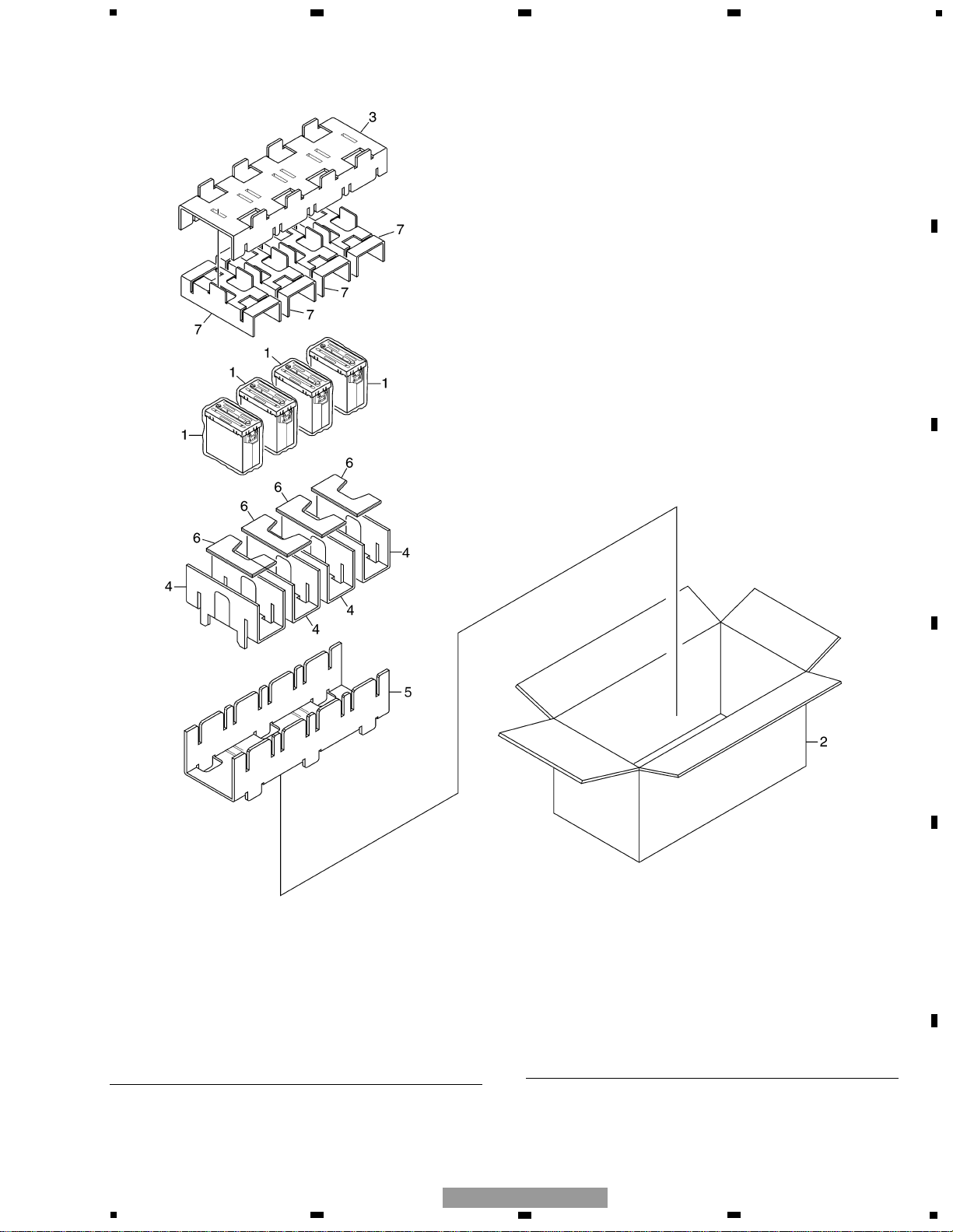
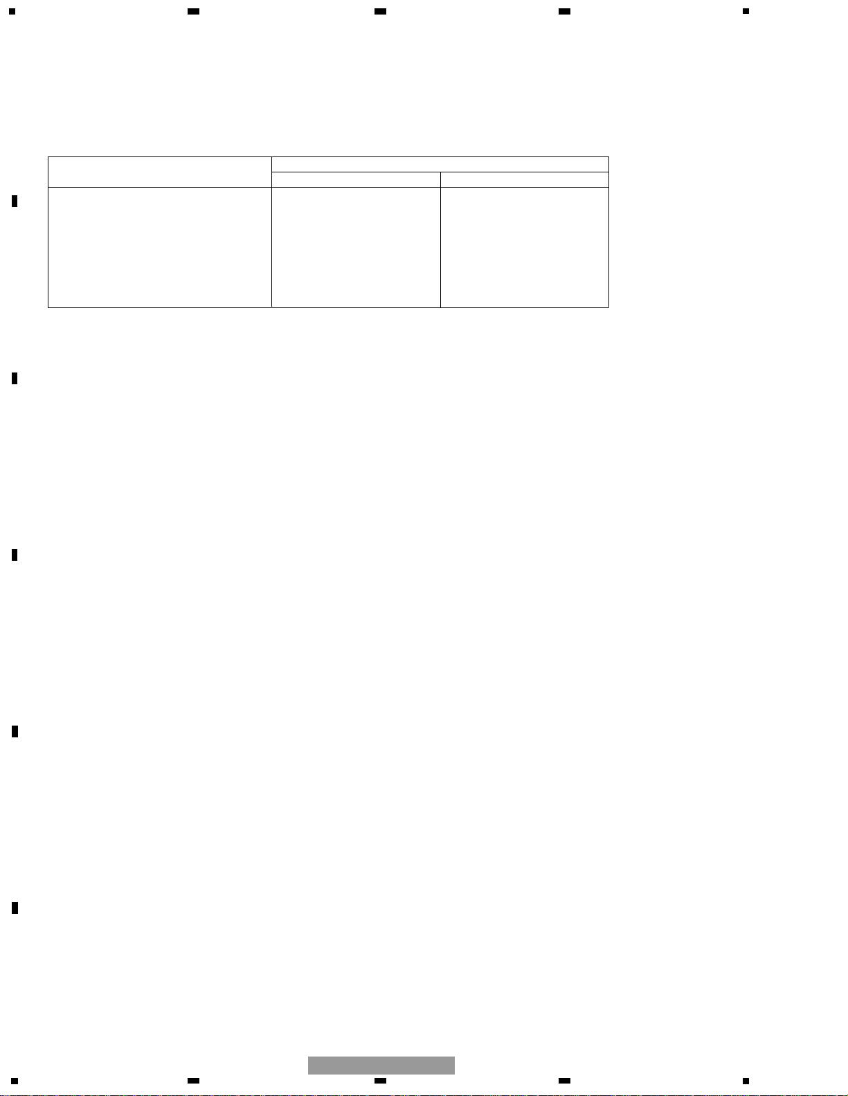
2. EXPLODED VIEWS AND PARTS LIST
2.1 PACKING
* 1 Polyethylene Bag CEG1317
2 Contain Box CHL4766
(DEH-MG2037ZF/XU/UC)
Contain Box CHL4767
(DEH-MG2137ZF/XU/UC)
3 Protector CHP2619
4 Protector CHP2620
5 Protector CHP2621
6 Protector CHP2622
7 Protector CHP2717
Mark No. Description Part No. Mark No. Description Part No.
NOTE:
- Parts marked by “*” are generally unavailable because they are not in our Master Spare Parts List.
- Screws adjacent to
∇ mark on the product are used for disassembly.
- For the applying amount of lubricants or glue, follow the instructions in this manual.
( In the case of no amount instructions, apply as you think it appropriate.)
- PACKING SECTION PARTS LIST
DEH-MG2037ZF/XU/UC
5
6
1
234
12
34
F
E
D
C
B
A
DEH-MG2037ZF/XU/UC
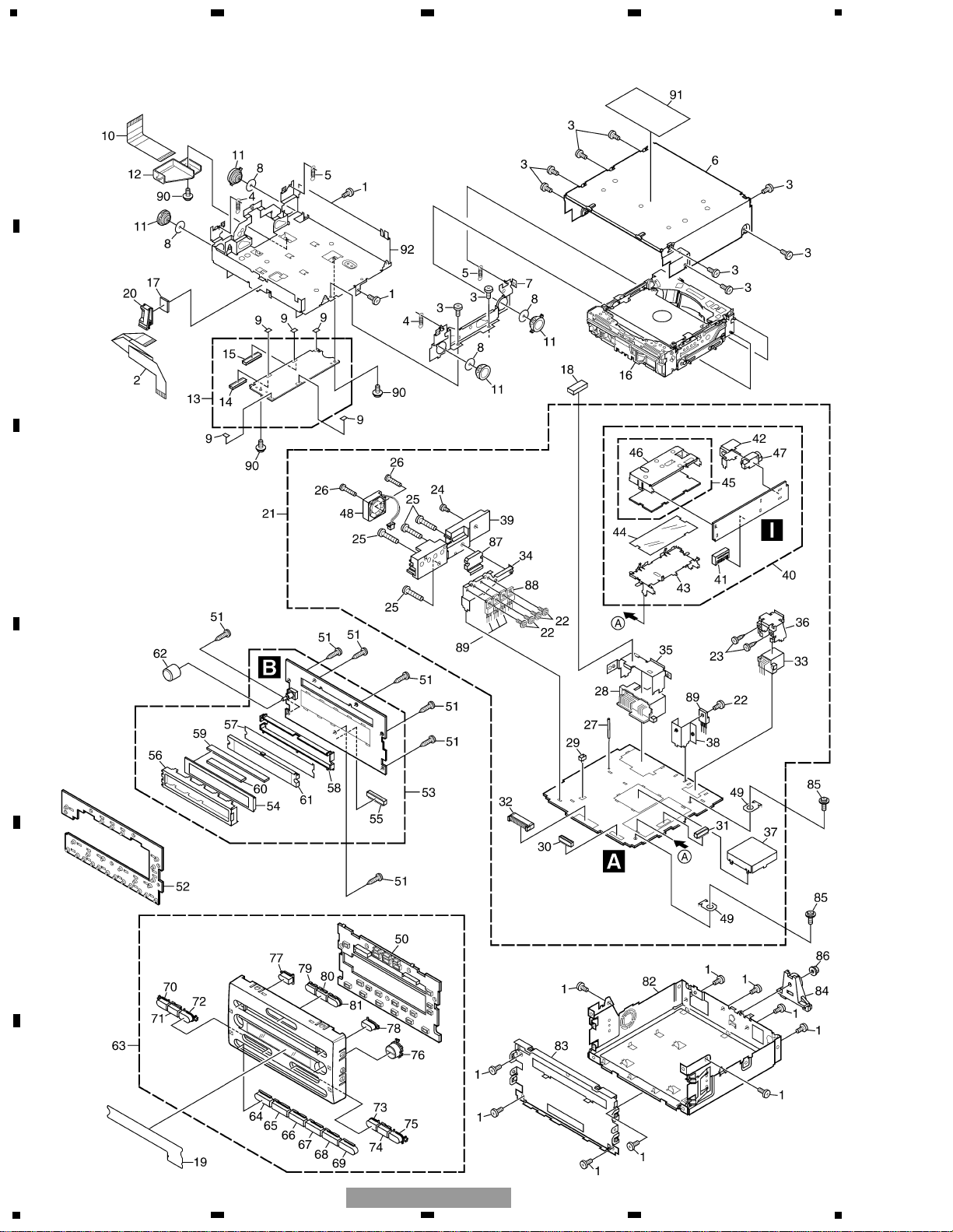
2.2 EXTERIOR

1 Screw BSZ26P060FTC
2 Connector CDE6820
3 Screw BSZ26P060FTC
4 Spring(Silver) CBH2481
5 Spring(Black) CBH2482
6 Case CNB2736
7 Bracket CNC9824
8 Sheet CNM5981
9 Sheet CNM8258
10 Flexible Cable CNP7340
11 Damper CNV6608
12 Holder CNV7225
13 Control Unit(G2BM) CWX2713
14 Connector(CN902) CKS1956
15 Connector(CN101) CKS4512
16
Service Mechanism Unit(G2BM)
CXX1659
17 Double Side Seal CNM7891
18 Cushion CNM8378
19 Sheet CNM8581
20 Clamper CNV7333
21 Mother Unit
See Contrast table(2)
22 Screw ASZ26P080FTC
23 Screw
See Contrast table(2)
24 Screw BSZ26P060FTC
25 Screw BSZ26P160FTC
26 Screw(M2.6x14) CBA1632
27 Clamper CEF1035
28 Plug(CN701) CKM1372
29 Plug(CN871) CKS1035
30 Connector(CN704) CKS3700
31 Connector(CN451) CKS4574
32 Connector(CN705) CKS4575
33 Connector(CN703)
See Contrast table(2)
34 Holder CNC9818
35 Holder CNC9819
36 Holder
See Contrast table(2)
37 Shield CNC9882
38 Holder CNC9906
39 Heat Sink CNR1640
40 Tuner Relay Unit CWM8263
41 Connector(CN411) CKS4573
42 Holder CNC9822
43 Holder CNC9823
44 Insulator CNM7679
45 FM/AM Tuner Unit CWE1561
46 Holder CNC8855
47 Antenna Jack(CN401) HKX1054
48 Fan Motor(M871) CXM1283
49 Terminal(CN452, 453) VNF1084
* 50 Housing CNV7075
51 Screw BPZ26P100FTC
52 Rubber CNV7078
53 Keyboard Unit CWM8236
54 LCD(LCD904) CAW1822
55 Connector(CN901) CKS4576
56 Holder CNC9815
57 Sheet CNM7787
58 Housing CNV7069
59 Connector CNV7599
60 Connector CNV7600
61 Lighting Conductor CNV7936
62 Knob Unit CXB8558
63 Grille Unit
See Contrast table(2)
64 Button(1) CAC7524
65 Button(2) CAC7530
66 Button(3) CAC7531
67 Button(4)
See Contrast table(2)
68 Button(5) CAC7535
69 Button(6) CAC7536
70 Button(SEEK DOWN) CAC7537
71 Button(SCAN) CAC7538
72 Button(SEEK UP) CAC7539
73 Button(TUNE DOWN) CAC7540
74 Button(MENU) CAC7541
75 Button(TUNE UP) CAC7542
76 Button(CLK/MUTE) CAC7543
77 Button(LOAD) CAC7544
78 Button(EJECT) CAC7545
79 Button(AM) CAC7546
80 Button(FM) CAC7547
81 Button(CD) CAC7548
82 Chassis Unit
See Contrast table(2)
83 Holder Unit CXC1377
84 Rail Guide HNV6756
85 Screw ISS26P055FTC
86 Nut NF50FTC
87 IC(IC101) TDA7384
88 Transistor(Q802) 2SD2375
89 Transistor
(Q809,851,855,863)2SB1185
90 Screw ISS26P060FTC
* 91 Label CRW1451
92 Chassis Unit CXB9212
7
5
6
7
8
F
E
D
C
B
A
5
6
7
8
DEH-MG2037ZF/XU/UC
Mark No. Description Part No. Mark No. Description Part No.
(1) EXTERIOR SECTION PARTS LIST
8
1
234
12
34
F
E
D
C
B
A
DEH-MG2037ZF/XU/UC
Part No.
Mark No. Symbol and Description DEH-MG2037ZF/XU/UC DEH-MG2137ZF/XU/UC
21 Mother Unit CWM8234 CWM8235
23 Screw BPZ26P080FTC Not used
33 Connector(CN703) CKX1067 Not used
36 Holder CNC9820 Not used
63 Grille Unit CXC2429 CXC2430
67 Button(4) CAC7534 CAC7549
82 Chassis Unit CXB8576 CXB9211
(2) CONTRAST TABLE
DEH-MG2037ZF/XU/UC and DEH-MG2137ZF/XU/UC are constructed the same except for the following:

9
5
6
7
8
F
E
D
C
B
A
5
6
7
8
DEH-MG2037ZF/XU/UC
10
1
234
12
34
F
E
D
C
B
A
DEH-MG2037ZF/XU/UC
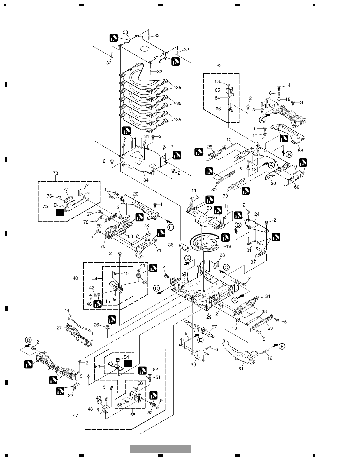
2.3 MECHANISM UNIT(G2BM)(SERVICE)(1)
1
1
1
3
3
1
3
1
1
3
3
3
F
3
3
3
1
1
1
3
2
D
1
1
3
1
1:GEM1043
2:GEM1042
3:GEM1024

11
5
6
7
8
F
E
D
C
B
A
5
6
7
8
DEH-MG2037ZF/XU/UC
Mark No. Description Part No. Mark No. Description Part No.
1 Screw BMZ20P020FZB
2 Screw BMZ20P025FTC
3 Screw(M2x2) CBA1556
4 Screw(M2x2.5) CBA1626
5 Screw(M2x2.5) CBA1609
6 Screw(M2x4.5) CBA1629
7 Spring CBH2460
8 Spring CBH2461
9 Spring CBH2484
10 Spring CBH2694
11 Spring CBH2486
12 Spring CBH2487
13 Spring CBH2500
14 Connector CDE6698
15 Collar CLA4329
16 Collar CLA4330
17 Collar CLA4331
18 Gear CND1649
19 Cam Gear CND1650
20 Frame CND1651
21 Steer CND1655
22 Arm CND1657
23 Bracket CND1658
24 Bracket CND1660
* 25 Lever CNC9953
26 Gear CNV6612
27 Holder CNV6648
28 Holder CNV6738
* 29 Chassis Unit CXC1642
* 30 Frame Unit CXC1643
* 31 Arm Unit CXC1647
32 Spring CBH2488
33 Holder Unit CXC1644
34 Holder Unit CXC1646
35 Tray Unit CXB6930
36 Lever Unit CXC1648
* 37 Lever Unit CXC1649
38 Lever Unit CXC1650
* 39 Lever Unit CXC1651
40 Cam Motor Assy CXB7522
41 Washer CBF1064
42 Gear CNV6610
43 Gear CNV6611
44 Motor Unit(-A) CXC1144
45 Screw JFZ20P020FTC
46 Washer YE20FTC
47 ELV Motor Assy CXB7523
48 Screw BMZ20P025FTC
49 Washer CBF1064
50 Holder CND1668
51 Gear CNV6634
52 Gear CNV6635
53 PCB Unit(LED) CWX2614
* 54 Connector(CN31) CKS4523
55 Motor Unit(M2) CXC1145
56 Screw JFZ20P020FTC
* 57 Arm Unit CXC1653
58 Bracket Unit CXC1654
* 59 Lever Unit CXC1658
* 60 Lever Unit CXC1659
* 61 Lever Unit CXC1661
62 Arm Assy CXB8822
63 Washer CBF1038
64 Spring CBH2489
65 Arm CNV6735
66 Bracket Unit CXC1652
67 Screw BMZ20P025FTC
68 Spring CBH2459
69 Volume(VR1) CCW1023
70 Bracket CND1652
71 Steer CND1656
72 Flexible PCB CNP6368
73 PCB Unit(SIDE) CWX2613
74 Connector(CN12) CKS3991
* 75 Connector(CN14) CKS4404
76 Connector(CN13) CKS4525
77 Connector(CN11) CKS4572
78 Lever Unit CXC1779
* 79 Lever Unit CXB9121
* 80 Lever Unit CXB9122
81 Screw JFZ20P020FTC
82 Washer CBF1037
- MECHANISM UNIT(G2BM)(SERVICE)(1) SECTION PARTS LIST
12
1
234
12
34
F
E
D
C
B
A
DEH-MG2037ZF/XU/UC
2
1
1
1
1
1
1
1
1
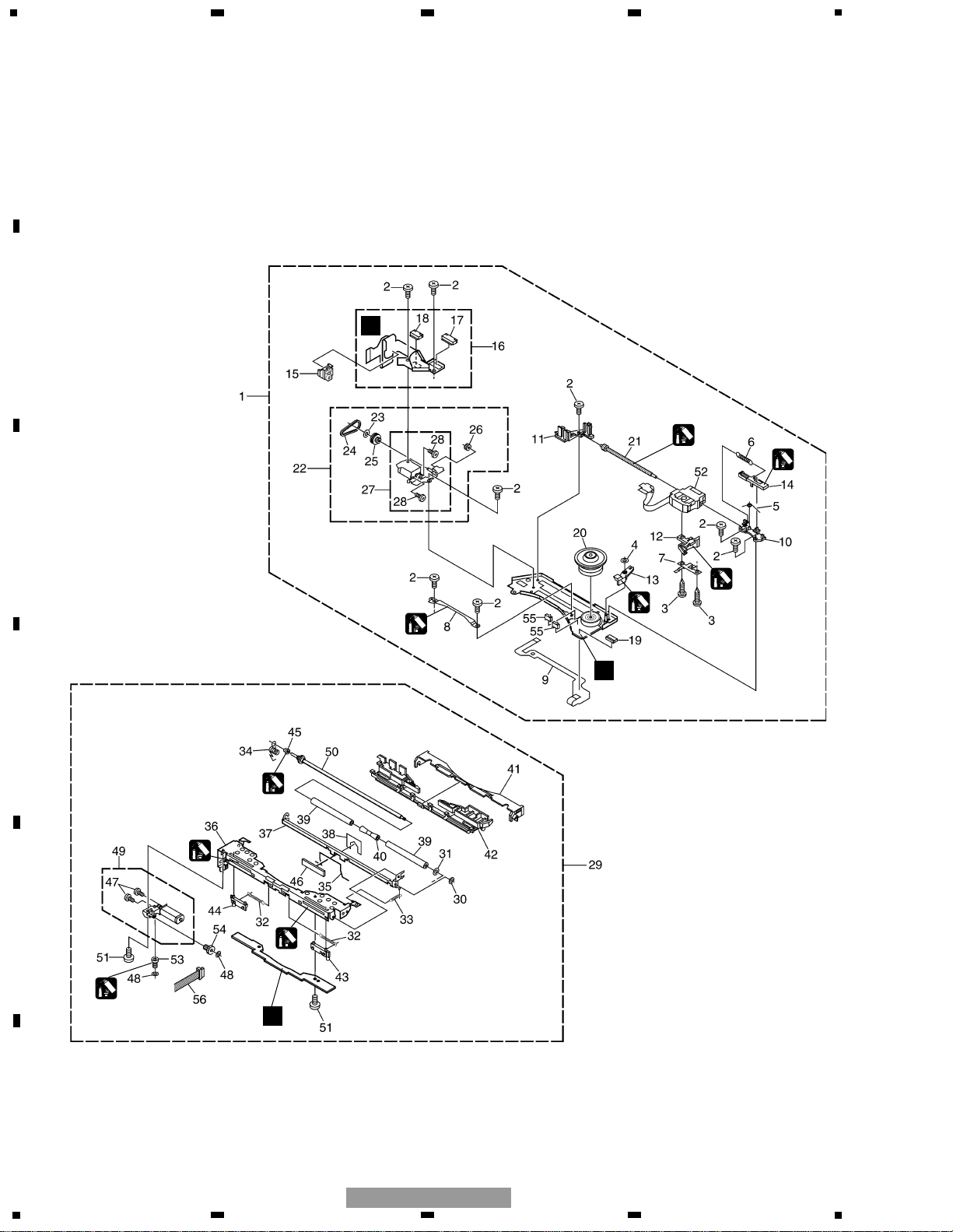
1:GEM1043
2:GEM1042
G
H
E
2.4 MECHANISM UNIT(G2BM)(SERVICE)(2)

13
5
6
7
8
F
E
D
C
B
A
5
6
7
8
DEH-MG2037ZF/XU/UC
Mark No. Description Part No. Mark No. Description Part No.
1 Carriage Mech. Assy(G2BM) CXB8844
2 Screw(M2x2) CBA1556
3 Screw(M2x6) CBA1628
4 Washer CBF1038
5 Spring CBH2453
6 Spring CBH2480
7 Spring CBL1521
* 8 Guide CNC9402
9 Flexible PCB CNP6217
10 Holder CNV6624
11 Holder CNV6625
12 Rack CNV6642
13 Arm CNV6731
14 Lever CNV6736
15 Holder CNV6737
16 PCB Unit CWX2611
17 Connector(CN41) CKS3785
18 Connector(CN42) CKS4508
19 Connector(CN1) CKS4508
20 Support Wheel Unit CXC1768
21 Screw Unit(-B) CXB7518
22 Carriage Motor Assy CXB7521
23 Washer CBF1038
24 Belt CNT1088
25 Pulley CNV6627
26 Gear CNV6629
27 Motor Unit(-A)(M3) CXC1143
28 Screw JFZ14P020FTC
29 Loading Mech. Assy CXB7525
30 Washer CBF1037
* 31 Washer CBF1075
* 32 Spring CBH2450
33 Spring CBH2452
* 34 Spring CBH2457
* 35 Spring CBH2580
* 36 Frame CND1653
* 37 Arm CND1654
* 38 Sheet CNM7295
39 Roller CNV6616
40 Collar CNV6617
* 41 Guide CNV6622
* 42 Holder CNV6636
* 43 Lever CNV6732
* 44 Lever CNV6733
45 Collar CNV6734
* 46 Holder CNV7144
47 Screw JFZ12P018FTC
48 Washer CBF1037
* 49 Motor Unit(-A) CXC1146
50 Shaft Unit(-C) CXB7528
51 Screw JFZ20P020FTC
52 PU Unit(PX1MP)(Service) CXX1600
* 53 Gear CNV6620
* 54 Gear CNV6621
55 Switch(S1,2) CSN1057
* 56 Connector CDE6674
- MECHANISM UNIT(G2BM)(SERVICE)(2) SECTION PARTS LIST

14
1
234
12
34
F
E
D
C
B
A
DEH-MG2037ZF/XU/UC
15
5
6
7
8
F
E
D
C
B
A
5
6
7
8
DEH-MG2037ZF/XU/UC
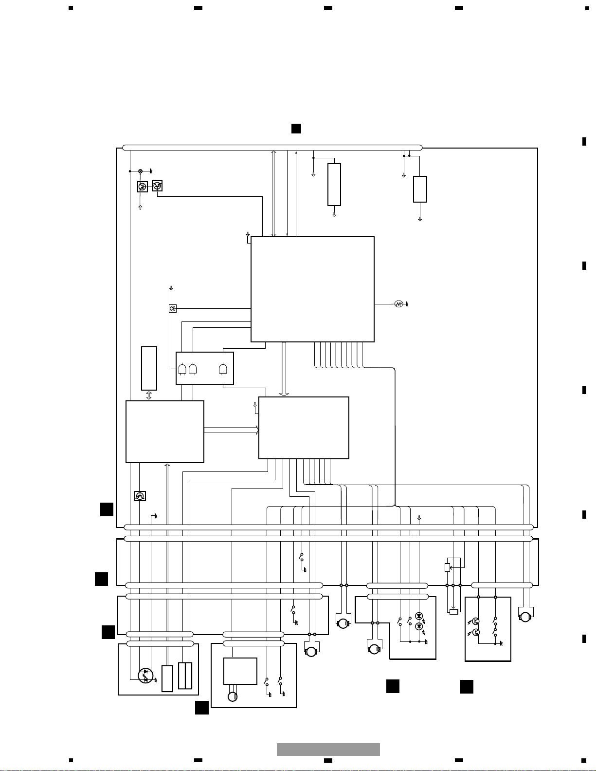
3. BLOCK DIAGRAM AND SCHEMATIC DIAGRAM
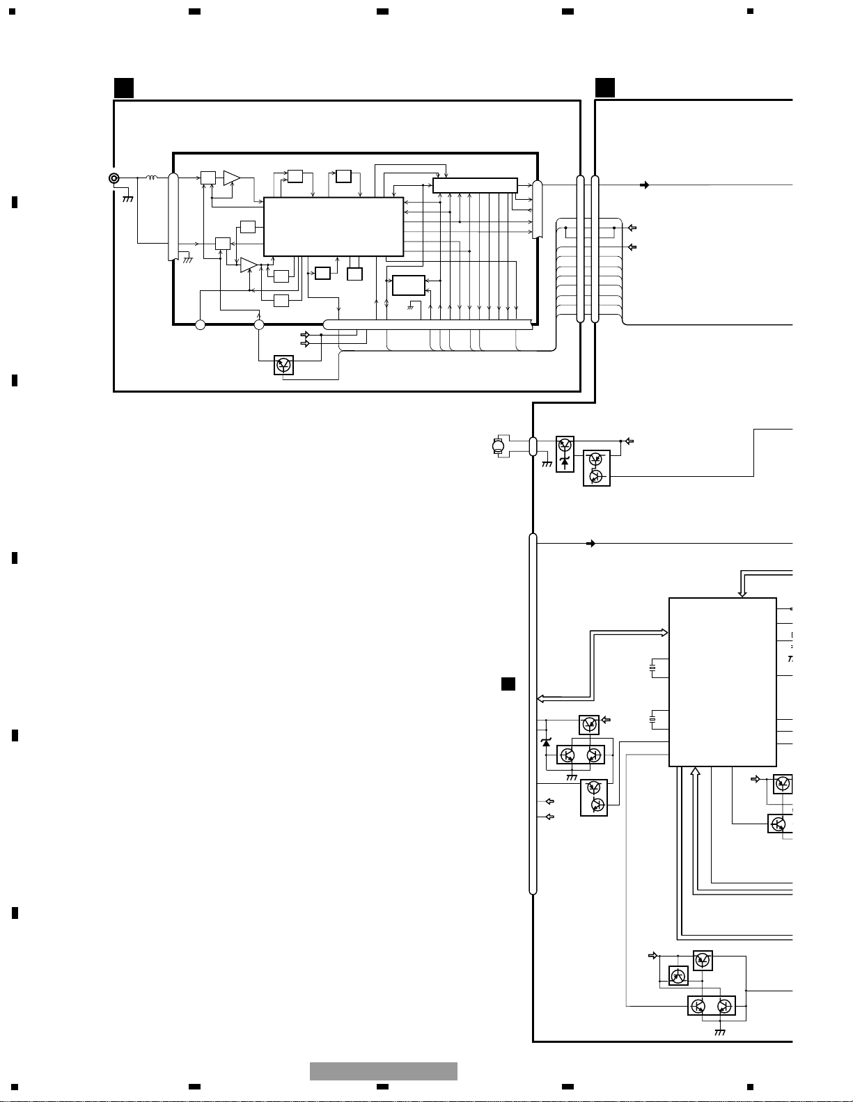
3.1 BLOCK DIAGRAM(1)
M
LOADING
VR1 ELV SENSE
VR11
S31 CAMLOAD
PU UNIT(PX1MP3)
(SERVICE)
PCB UNIT(M2 UNIT)
HOLOGRAM
UNIT
FOCUS ACT
TRACKING ACT
MD
LD+
LD-
LD
MD
FO+
TO+
CN41
M
M
SPINDLE
M3 CRG
CLAMP
10
2
1
16
14
A+C,B+D,
E,F
2
A3
3
5
A2
A1
IC 1
BA6849FS
MOTOR
DRIVER
CN1
EC
19
S2 CLAMP
HOME
S1 HOME
5
2
1
5
2
1
CN42
S41 LOAD3
PCB UNIT
231413
28
26
6
9
10
1
11
12
231413
28
26
6
9
10
1
11
12
PCB UNIT(SIDE)
CN12
S11 CAMCLMP
M
M1 CAMGEAR
CN31
M
M2 ELV
S32 CAMEOK
D31
D32
PCB UNIT
(LED)
CN14
CN13
Q22 Q21
S21 LOAD1
S22 LOAD2
PCB UNIT
(LOAD)
2
1
4
5
CN11
MD
233233
LD+
LD-
FOP
18
TOP
20
SIN(EC)
40
CLAMP
36
HOME
37
LOADSW2
45
50
COP34COM
35
CGM
3
CGP
1
ELP
15
ELM
13
CAMEOK
11
CAMLOAD
10
LED
12
ELVSNS
46
EREF
48
LOADPHT
7
LOADSW1
8
LOP
6
LOM
5
233233
18
20
40
36
37
45
50
34
35
3
1
15
13
11
10
12
46
48
7
8
6
5
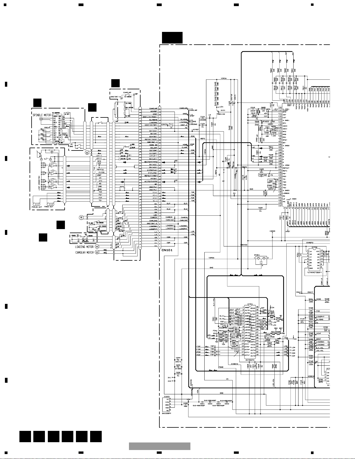
CONTROL UNIT(G2BM)
Q101
140
PD
RF AMP, CD DECODER,
MP3 DECODER,
DIGITAL SERVO/ DATA
PROCESSOR
141
LD
A+C,B+D,E,F
L-OUT
35
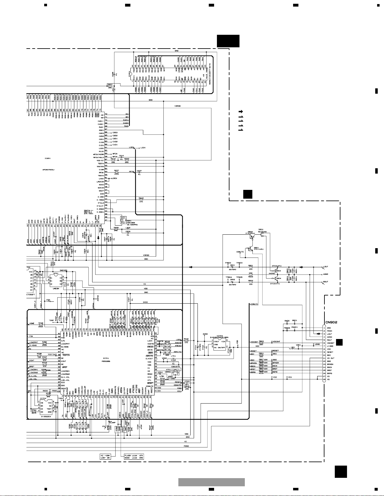
IC 201
UPD63760GJ
IC701
PE5335B
MECHANISM
CONTROLLER
55
3VDD
BVDD
3+3ch
DRIVER
IC 301
BD7962FM
ELV1,ELV2,LO1,LO2,
CG1,CG2
26
29
CONT
MUTE
MOTOR CONTROL
14
VD
SERVO EQUALIZER OUTPUT
FD,TD,SD,MD
18
15
OUT1+
OUT2-
Q602
Q603
CD MUTE
VD
Q601
30
CDMUTE
CN101
CN902
BSI,BSO,BSCK,BRXEN,BSRQ,BRST
31
reset
LOUT
24
VDCONT
9
8
3
RESET
VDCONT
VDD
VD
VD
17
18
IC 203
BA033SFP
3.3V REGULATOR
4
2
V3R3A
S-818A33AUC-BGN
3.3V REGULATOR
3
2
IC 703
3VDD
76
TEMP
26
OPOUT
COP
COM
ELP
ELM
LOP
LOM
CGM
CGP
19
20
2
3
21
22
34
35
OUT3+
OUT3-
OUT5-
OUT5+
OUT4+
OUT4-
OUT6+
OUT6-
VD
CLAMP
HOME
LOADSW2
CAMCLMP
ELVSNS
EREF
13
77
90
5
82
75
CLAMP
HOME
LOADSW2
CAMCLMP
EREF
CAMEOK
3
CAMEOK
CAMLOAD
4
CAMLOAD
LOADPHT
81
LOADPHT
LOADSW1
90
LOADSW1
ELVSENS
C
G
F
H
D
E
IC204
MSM51V18165FP-60TS
DRAM
10
2
1
16
14
6
IC702
TC74VHCT08AFT
53
RFOK
12
20
wait
2
Q701
8
11
3
27
79
xwait
FOK
10
VDD
SWDVDD
14
17
adena
A
CN704
1
1
4
4
5
5
778
8
16
26
MUTE
XOUT
XIN
SYSTEM CONTROL
IC 601(2/2)
PD5754A
CN401
VDDT
VCCT
ANTENNA
JACK
1
2
V
CN704
13
X601
15
dsprst,dsperr,I
69
swvdd
BLPWR
3
BLPWR
3
Lch
Q401
LOCL
PDIO
I
TUNER RELAY UNIT
FM/AM TUNER UNIT
18
3
8
17
6
VDD
BRST,BRXEN,BSRQ
BDATA,BSCK
Q863
Q864
B.UP
Q8
Q85
B.UP
ILMOUT
BLPWR
VD REGULATOR
C
CN902
9
RESET
VD
VDCONT
14 14
11
22
33
11 11
66
77
LOCL
VCCT
VDDT
pllck
PLLCE
88
99
10 10
PLLDIO
pllce@
SL
16 16
17 17
SD
st
LOCL
VCCT
VDDT
pllck
PLLCE
PLLDIO
pllce@
SL
SD
st
CN451
CN411
Q865
CDPWR
44
Q855
Q853
B.UP
Q854
M
FAN
MOTOR
M871
2
1
CN871
Q871
Q872
B.UP
FANPWR
38
SWPWR
23
swclpin
65
LOTIN0
66
LOTIN1
73
wakeup
4
20
rotint
kdt)-kdt
LCDCE,LCDINH
VCC
VDD
A
MOTHER UNIT
SCLKOUT
SCLKIN
11
X602
10
IC 3
EEPROM
28
27
FM/AM 1ST IF 10.7MHz
T51 Q51 CF51
CF52 CF53
IC1
MIXER, IF AMP, DET.
6
21
18
LDET
COMP
222510 14 12 15 16 8 13 2 3 4
CF202
VDD
VCC
DI/DO
CE2CKCE1
SDBWSLFMSD
NL1
NL2
IC 2 FM MPX
AMANT
FMANT
ATT
ATT
AMRF
FMRF
IMG ADJ
RF ADJ
X901
10.25MHz
ANT ADJ
LOCL
23
LOCH
AMDET
MPXREF 41kHz
AM 2ND IF
450kHz
19
CREQ
11
DGND
1
STIND
L ch
5
R ch
924
AMDET
FMLOCL
20
177
AMPNS
WC
26
RFGND
AMIN
1
234
12
34
F
E
D
C
B
A
DEH-MG2037ZF/XU/UC
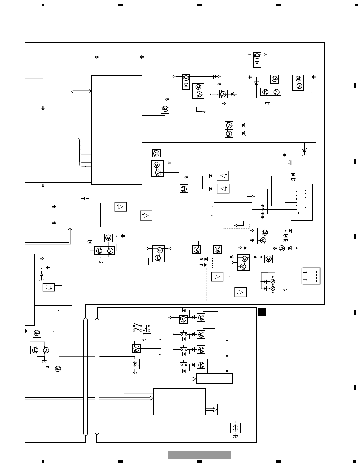
3.2 BLOCK DIAGRAM(2)
17
18
916
85
41
SYSPWR
VDD
B.UP
Q810
VDD REGULATOR
Q802
12
1
bsens
asens
VDD
LOCL
21
27
SD
SL
PLLCE
pck
pllce@
PDO
14
RL
5
FL
26
MUTE
ILL+B
ACC
85
82
97
LIN-1
81
LIN-2
82
84
2
83
1
SYSTEM CONTROL
RESET
IC 601(1/2)
PD5754A
IC 301
PM2010A
S-80843CNUA-B84
reset
Q803
VDD
27
4
CN705
2
Q801
TUN L
CDX6L
RL+
FL+
RL-
FL-
CN701
ILMI
95
A SENSE
PDI
100
PDIO
VCC
DSP VDD (3.3V)REGULATOR
VDD
3,8,18,27,37,49,76,77,96
syspwr
70
Q809
Q808
B.UP
SYSPW
VCC
Q851
Q852
BL+B
Q710
Q709
IC 602
VDD
5
B.UP
B SENSE
ILMIN
RESET
NJM4558V
IC303
21
NJM4558V
IC302
21
9
7
17
19
FL+
FL-
RL+
RL-
FLIN
11
RLIN
15
22 4
POWER AMP
IC 101
TDA7384
STBYMUTE
B.UP
6,20
SYSPW
Q807
Q806
VCC REGULATOR
Q804
Q602
VDD
Q381
Q387
1/2VCC
Q805
VCC
1/2VCC REGULATOR
ACC
Q711
ilmint
19
PWMIN
6
FANPWR
49
Q601
SWVDD
SYSPW
Q102Q101
HMUTE
HMUTE
STMUTE
NJM4558V
IC304(2/2)
67
NJM4558V
IC304(1/2)
21
24
SWOUT
SW+
SW-
Q385
Q386
VCC
Q389
SWPWR
Q388
SWMUTE
SWPWR
38
ECLD
Q384
SWCDIN
SWCDIN
23
SWVDD
Q604
MUTE
SWMUTE
Q605
Q382
SWPWR
VCC
24
19
18
ROTIN1
ROTIN0
wakeup
65
66
73
TC7S86F
IC 605
1
2
4
20
rotint
kdt)-kdt$,kst)-kst%
LCDCE,LCDINH,LCDCLK,LCDDT,LCDDT,
Q383
B.UP
BACKUP
ILL+
CN703
IC112
76
NJM2904V
IC111
76
NJM2904V
Q104
RLPO
FLPO
clipin
24
SWVDD
SWVDD
XOXI
1
X301
2
st
81
DIAGNOSTICS
PDH053C : DEH-MG2037ZF
PDH054C : DEH-MG2137ZF
IC 604
ROMDATA,
ROMCK,EPCE
DEH-MG2037ZF
ILL+B
SWDVDD
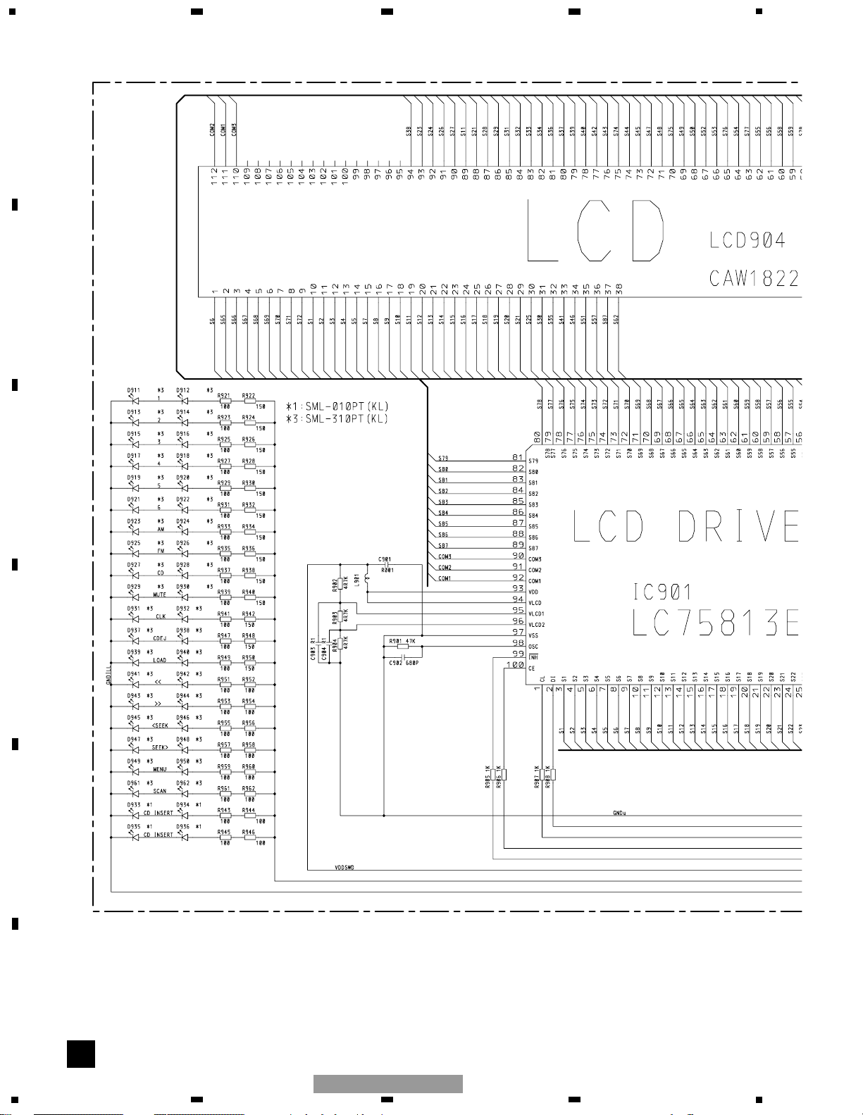
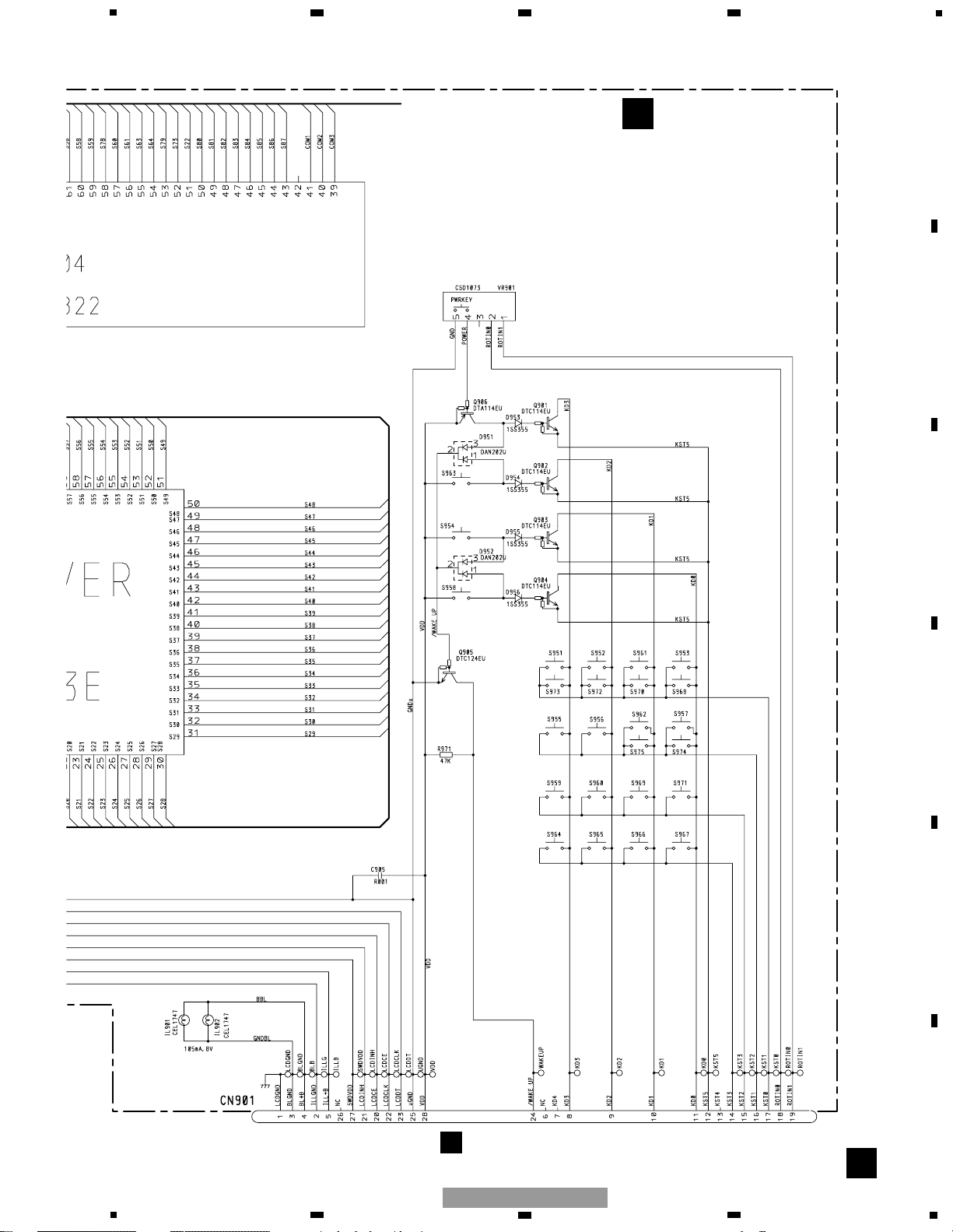
IC 901
LC75813E
LCD DRIVER
KEY MATRIX
5
27
VDD
93
CN901
KEYBOARD UNIT
LCD 904
B
4
BL+B
ILLUMINATION
VR901
2
1
18
19
ROTIN1
ROTIN0
ROTIN1
ROTIN0
LCD BACKLIGHT
4
5
VOLUME/POWER
Q906
Q901
VDD
KST5
Q902
KST5
CLOCK
Q903
KST5
LOAD
Q904
KST5
EJECT
KD3
KD2
KD1
KD0
Q905
wakeup
24
wakeup
kdt)-kdt$,kst)-kst%
LCDCE,LCDINH,LCDCLK,LCDDT,LCDDT,
5
6
7
8
F
E
D
C
B
A
5
6
7
8
DEH-MG2037ZF/XU/UC
A-a A-b
A-a
A-b
A-b
A-a
Large size
SCH diagram
Guide page
Detailed page
Note: When ordering service parts, be sure to refer to " EXPLODED VIEWS AND PARTS LIST" or
"ELECTRICAL PARTS LIST".
A-a
A
B
CN901
I
CN411
C
CN902
FAN MOTOR
DSP
SYSTEM CONTROLLER
M871
CXM1283
FM:-22.5dBs
AM:-33.0dBs
CD:-1.0dBs
CD:+0.0dBs (0dBs 1kHz)
FM:-1.5dBs
AM:-11.0dBs
CD:+7.0dBs
18
1
234
12
34
F
E
D
C
B
A
DEH-MG2037ZF/XU/UC
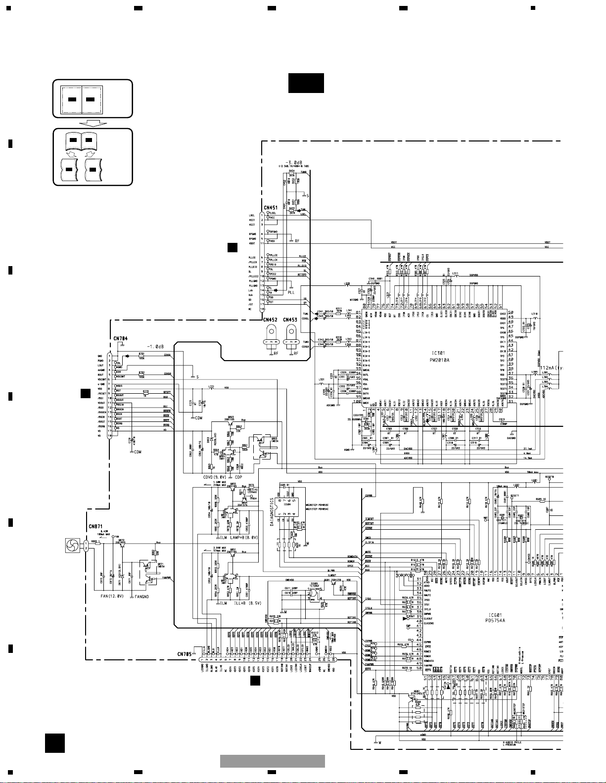
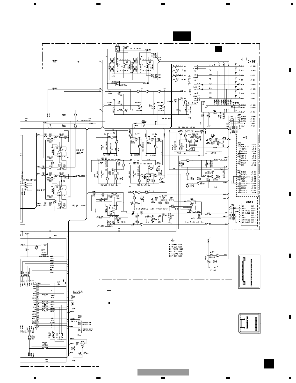
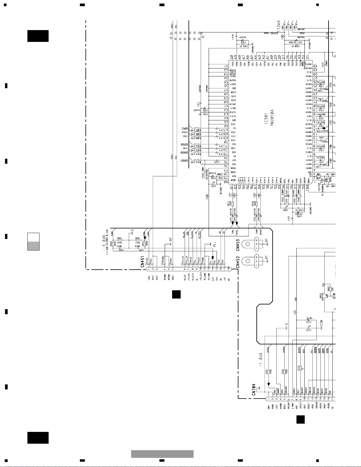
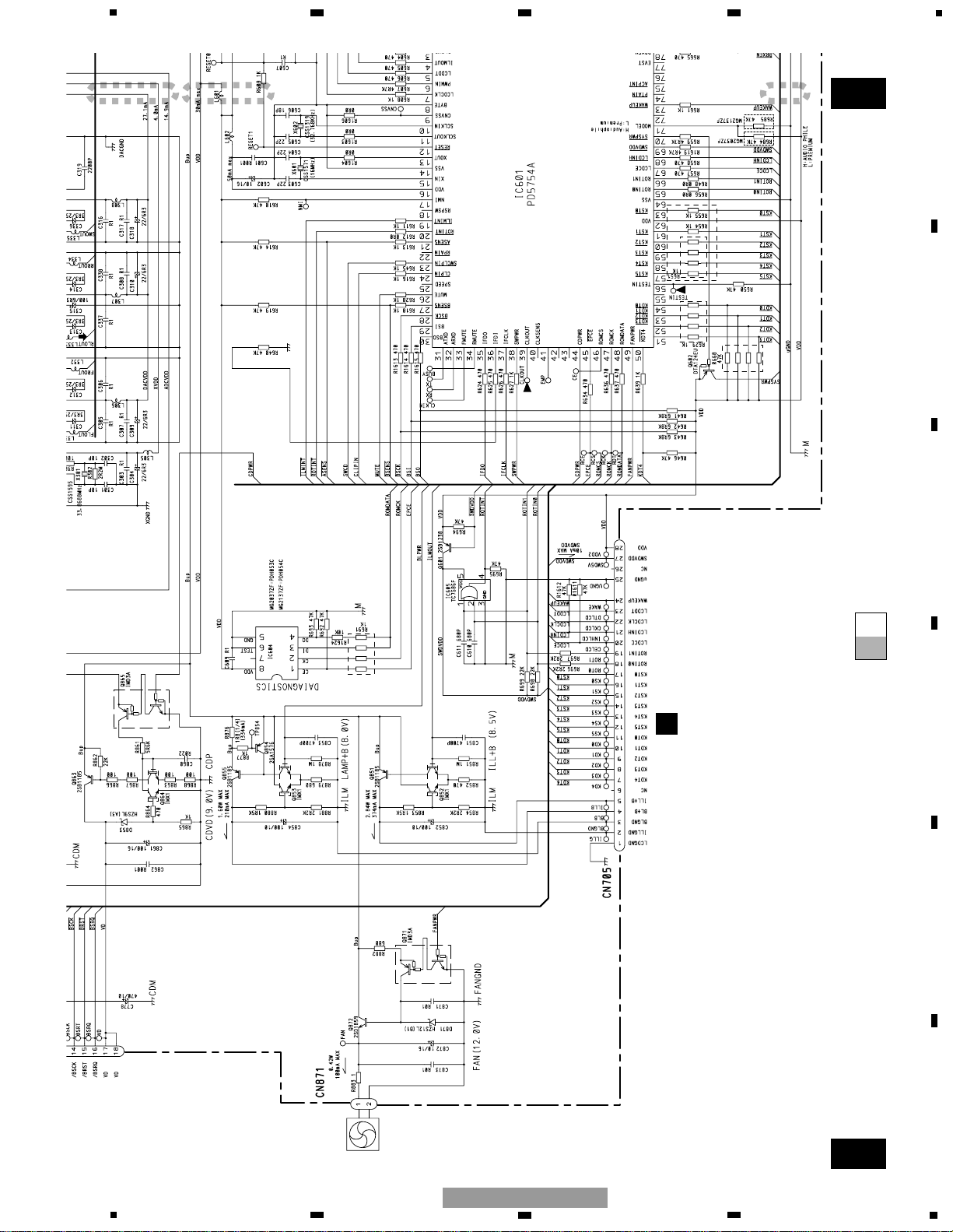
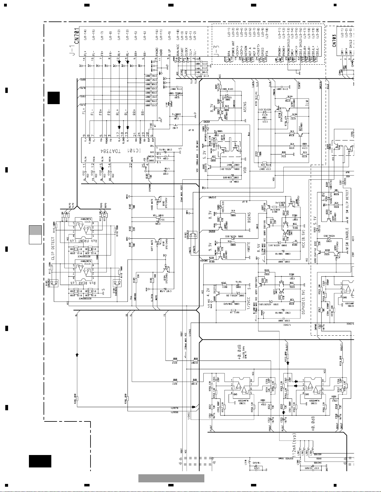
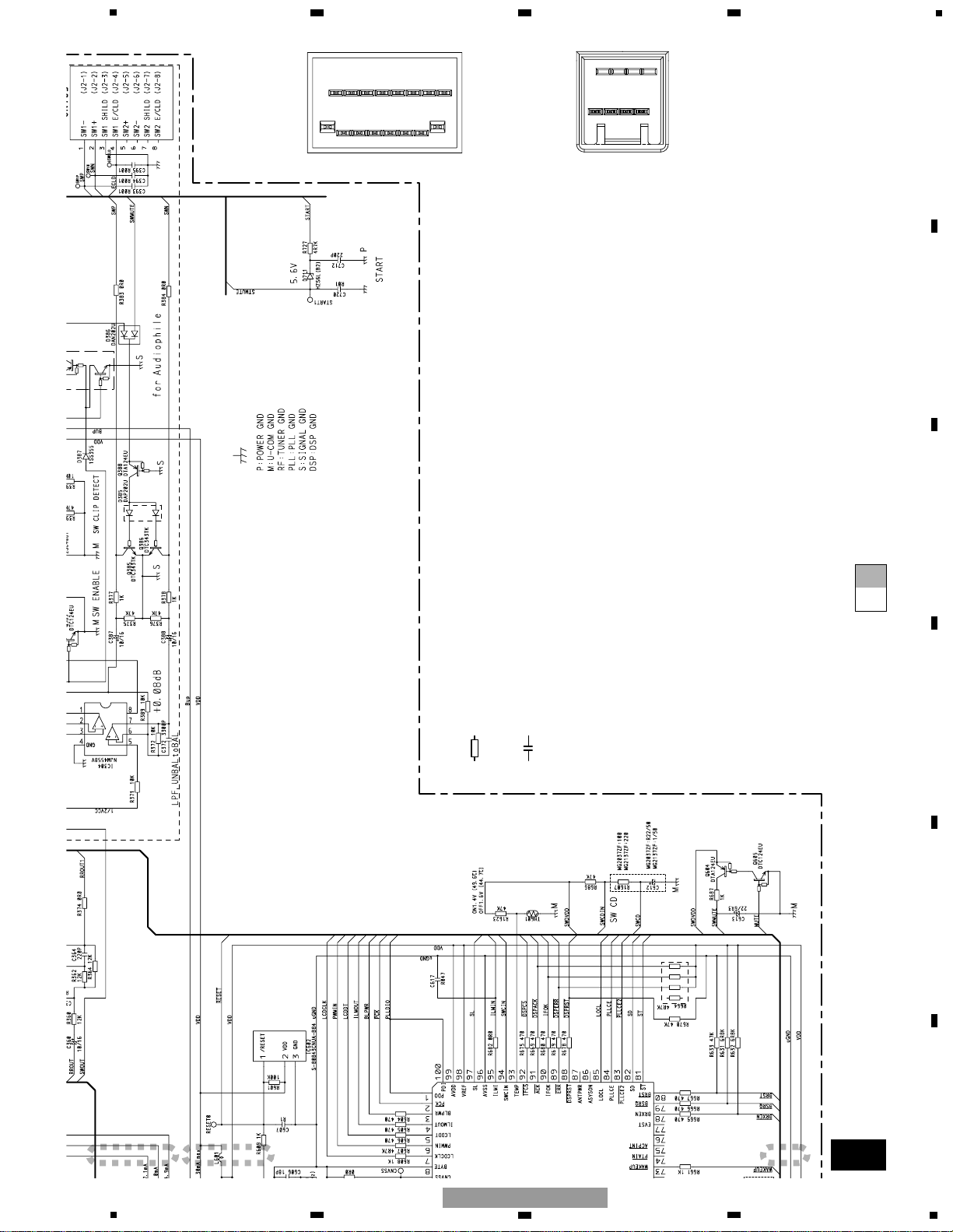
3.3 OVERALL CONNECTION DIAGRAM(GUIDE PAGE)
A-b
A
Decimal points for resistor
and capacitor fixed values
are expressed as :
2.2 2R2
0.022 R022
←
←
Symbol indicates a resistor.
No differentiation is made between chip resistors and
discrete resistors.
NOTE :
Symbol indicates a capacitor.
No differentiation is made between chip capacitors and
discrete capacitors.
A
MOTHER UNIT
POWER AMP
DEH-MG2037ZF
Not used
16
18
9
4
8
1
5
CN701
CN703
FM:+24.5dBs
AM:+13.0dBs
CD:+33.0dBs
19
5
6
7
8
F
E
D
C
B
A
5
6
7
8
DEH-MG2037ZF/XU/UC
A-a
A-b
A-a
A-a
A-b
1
I
CN411
C
CN902
DSP
FM:-22.5dBs
AM:-33.0dBs
CD:-1.0dBs
CD:+0.0dBs (0dBs 1kHz)
FM:-1.5dBs
AM:-11.0dBs
CD:+7.0dBs
20
1
234
12
34
F
E
D
C
B
A
DEH-MG2037ZF/XU/UC
A-a
A-b
A-a
A-a
A-b
2
3
4
B
CN901
FAN MOTOR
SYSTEM CONTROLLER
M871
CXM1283
21
5
6
7
8
F
E
D
C
B
A
5
6
7
8
DEH-MG2037ZF/XU/UC
A-a
A-b
A-b
1
A
MOTHER UNIT
POWER AMP
DEH-MG2037ZF
Not used
FM:+24.5dBs
AM:+13.0dBs
CD:+33.0dBs
22
1
234
12
34
F
E
D
C
B
A
DEH-MG2037ZF/XU/UC
A-a
A-b
A-b
2
3
4
Decimal points for resistor
and capacitor fixed values
are expressed as :
2.2 2R2
0.022 R022
←
←
Symbol indicates a resistor.
No differentiation is made between chip resistors and
discrete resistors.
NOTE :
Symbol indicates a capacitor.
No differentiation is made between chip capacitors and
discrete capacitors.
16
18
9
4
8
1
5
CN701
CN703
23
5
6
7
8
F
E
D
C
B
A
5
6
7
8
DEH-MG2037ZF/XU/UC
24
B
1
234
12
34
F
E
D
C
B
A
DEH-MG2037ZF/XU/UC
3.4 KEYBOARD UNIT
25
B
B
KEYBOARD UNIT
A
CN705
VOLUME/POWER
1346
25
SEEK
DOWN
SEEK UP
AMSCAN
TUNE/DISC
UP
TUNE/DISC
DOWN
MENUCDFMMUTE
EJECT
LOAD
CLK
5
6
7
8
F
E
D
C
B
A
5
6
7
8
DEH-MG2037ZF/XU/UC
C-a
C D E
F G H
1
2
3
4
5
6
7
8
1
2
3
4
5
6
7
8
9
10
11
12
13
14
15
16
17
18
19
20
21
22
23
24
25
26
27
28
29
30
CRG MOTOR
M3 CXC1143
LOAD3
S41
CSN1051
1K(B)
ELEVATION MOTOR
M2 CXC1145
CAMEOK
CAMLOAD
GR
BL
M1 CXC1144
LOAD1
LOAD2
1
2
3
vcc
1
2
3
4
5
6
7
8
1
2
3
4
5
1
2
3
4
5
6
7
8
9
10
11
12
13
14
15
16
17
18
19
20
21
22
23
24
25
26
27
28
29
30
6
7
8
9
5
4
3
2
1
14
15
16
17
6
7
8
9
5
4
3
2
1
PU UNIT(SERVICE)(PX1MP3)
14
15
16
17
F
PCB UNIT
(SIDE)
G
PCB UNIT
H
PCB UNIT (M2 UNIT)
D
PCB UNIT
(LED)
E
PCB UNIT
(LOAD)
3+3ch DRIVER
MOTOR DRIVER
5
12
13
24
CN42
CN1
CLAMP
HOME
S2
S1
CSN1057
CSN1057
CN12
VR1
ELVSENSE
CCW1023
10K
CN11
L1
CN14
CN31
RE
WH
1
2
3
4
5
6
7
8
9
10
11
12
13
1
2
3
4
5
6
7
8
9
10
11
12
13
CN41
CN13
RF AMP, CD
MP3 DECOD
DIGITAL SE
PROCESSO
T
SL
SLSL
SL
SL
T
T
TT
T
T
T
T
T
SLSL
SL
SL
SL
T
F
F
T
T
F
F
T
T
F
F
T
F
F
T
T
C
S
C
S
S
C
F
T
C
T
F
S
C
C
S
C
C
S
C
C
S
C
S
T
F
S
C
2
3
4
@
8
6
7
%
5
0
1
26
1
234
12
34
F
E
D
C
B
A
DEH-MG2037ZF/XU/UC
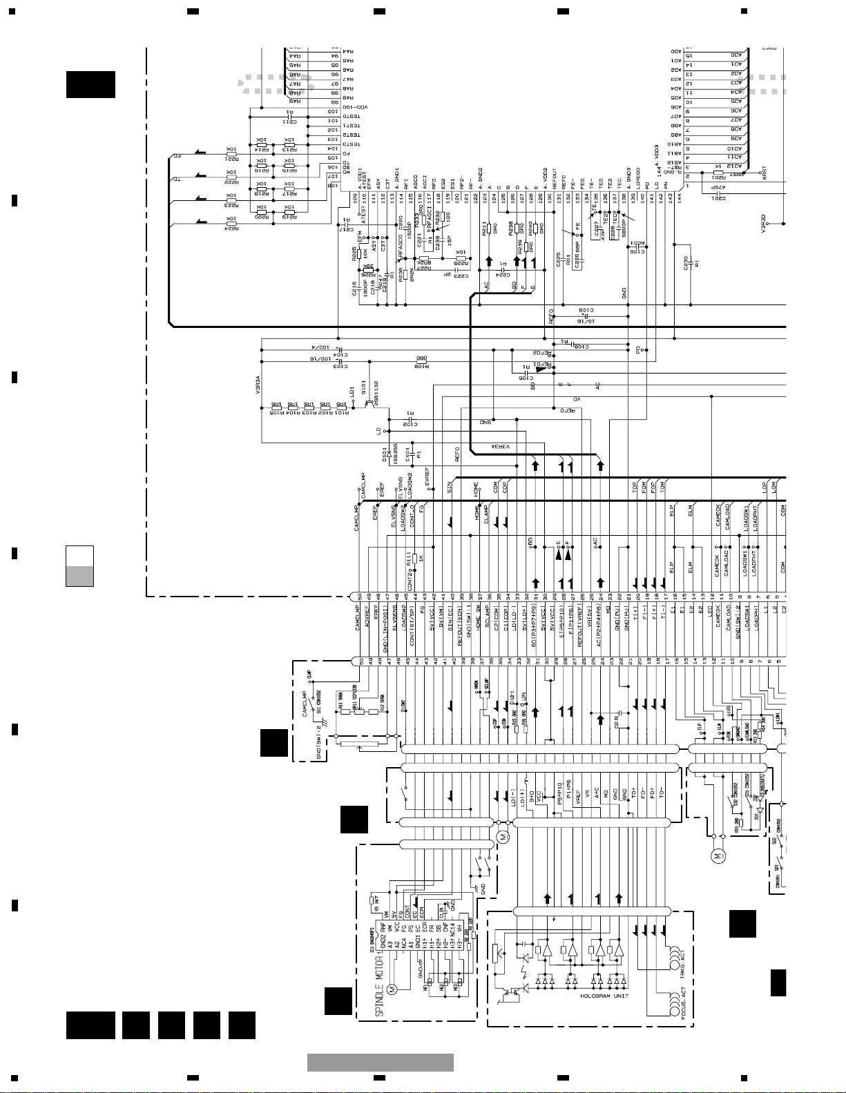
3.5 CD MECHANISM MODULE(GUIDE PAGE)
C-b
C
A
CN704
C
CONTROL UNIT(G2BM)
MECHANISM CONTROLLER
RAM
RF AMP, CD DECODER,
MP3 DECODER,
DIGITAL SERVO/ DATA
PROCESSOR
SL
SL
SL
SL
F
SL
SIGNAL LINE
FOCUS SERVO LINE
TRACKING SERVO LINE
CARRIAGE SERVO LINE
SPINDLE SERVO LINE
T
C
S
9
#
$
!
27
5
6
7
8
F
E
D
C
B
A
5
6
7
8
DEH-MG2037ZF/XU/UC
A-a
C-b
C-a
C-a
C-b
F G HD
1
2
1234567
8
123456789
101112131415161718192021222324252627282930
CRG MOTOR
M3 CXC1143
LOAD3
S41
CSN1051
1K(B)
ELEVATION MOTOR
M2 CXC1145
CAMEOK
CAMLOAD
LOAD1
LOAD2
1
2
vcc
1234567
8
1
123456789
101112131415161718192021222324252627282930
678954321
141516
17
678954321
PU UNIT(SERVICE)(PX1MP3)
141516
17
F
PCB UNIT
(SIDE)
G
PCB UNIT
H
PCB UNIT (M2 UNIT)
D
PCB UNIT
(LED)
E
PCB UNIT
MOTOR DRIVER
5
12
13
24
CN42
CN1
CLAMP
HOME
S2
S1
CSN1057
CSN1057
CN12
VR1
ELVSENSE
CCW1023
10K
CN11
L1
CN14
CN31
RE
WH
1
2
345
678
9
10
11
12
13
1
2
345
678
9
10
11
12
13
CN41
CN13
RF AMP,
MP3 DEC
DIGITAL
PROCES
T
SL
SLSL
SL
SL
T
T
TT
T
T
T
T
T
SLSL
SL
SL
SL
T
F
F
T
T
F
F
T
T
F
F
T
C
S
C
C
S
C
C
S
C
S
T
F
S
C
@
8
6
5
0
28
1
234
12
34
F
E
D
C
B
A
DEH-MG2037ZF/XU/UC
 Loading...