

Page 1
efiic
CASSETTE TAPE DECK
n
Page 2
MODEL
I
Type
CT-F950 COMES
I
IN
Voltage
SIX
VERSIONS
DISTINGUISHED
I
AS
FOLLOWS:
Remarks
I
I
I
KC
I
HE
I
HB
D
DIG
0
This service manual
refer to the additional service manuals
1
I
I
AC
120vonly
AC 120v only
AC 220V and 240V (Switchable)
AC 220V and 240V (Switchable)
AC 120V. 220V and 240V (Switchable)
AC 120V. 220V and 240V (Switchable)
is
applicable to the CT.F950/KU . For servicing of the other types. please
.
I
U.S.A. model
I
Canada model
1
Europe model
I
United Kingdom
General export model
U.S. Military model
model
CONTENTS
1 . SPECIFICATION
2
.
FRONTPANEL FACILITIES
.
LEVEL DIAGRAM
3
4 . DISASSEMBLY
.
PARTS LOCATION
5
6
.
BLOCKDIAGRAM
.
CIRCUIT DESCRIPTIONS
7
7.1 Recording and playback circuit
7.2 Tape selector circuit
7.3 Level meter
7.4 Electronic counter 16
7.5 Dolby NR processor circuit 17
7.6 Control circuit
7.7 Mutingcircuit
.
MECHANICAL ADJUSTMENTS 12.1 Miscellaneous parts
8
8.1 Pinch roller pressure adjustment
8.2 Tape speed adjustment
8.3 Tape guide adjustment
9 . ELECTRICAL ADJUSTMENTS 12.5 Mother assembly (RWX-359)
9.1 Head azimuth adjustment
9.2 Playback equalizer adjustment
9.3 Playback
9.4 Level meter OdB adjustment
9.5 Approximate adjustment
9.6 Erasure current adjustment
9.7 Bias trap adjustment 33
9.8 Approximate adjustment
recording current
recording bias
.....................
.............
....................
......................
...................
...................
.......
..............
....................
...............
.........
..................
..................
......
............
.............
...........
.......
level
adjustment
..........
.........
of
.................
..........
..............
..................
of
3 9.9 Recording equalizer and variable
4
6
8
11
13
15
15
16
18
27 PATTERNS AND PARTS LIST
30 12.2 Connection diagram
30 12.3
30
31 12.6
32 12.7 Sensing assembly
32 12.8 Indicator assembly
32 12.9
33
33
9.1
9.1 1 Recording
9.12 Output
9.13 Recording dolby
9.14 Playback dolby NR adjustment 36
.
PACKING
10
.
EXPLODED
.
SCHEMATIC DIAGRAMS
12
.
34
.
13
equalizer adjustments
0
Recording and playback frequency
response adjustment 34
level
level
adjustment
..........................
11.1 Exterior
11.2 Mechanism assembly 45
11.3 Panel stay 48
Schematic diagram
12.4 Function switch assembly
Volume assembly
Indicator amplifier assembly
12.10 Integrated amplifier assembly (RWX.360) . 71
12.1 1 Power supply assembly(RWR.067)
12.12 Control assembly(RWG.103)
12.13
12.14 Tape selector assembly
12.1
TROUBLE SHOOTING
REC
5
Fuse assembly
......................
.....................
EQassembly(RWX-361) 81
.............
..............
adiustment
............
NR
adjustment
..............
P.C.
BOARD
list
............
..............
...............
................
................
...............
..................
.................
......
......
.......
..........
.........
(RWX-328) . 67
.....
.........
........
.......
.....
I
I
I
I
34
35
36
36
41
42
50
51
54
57
58
63
63
64
73
77
83
84
85
Page 3
1.
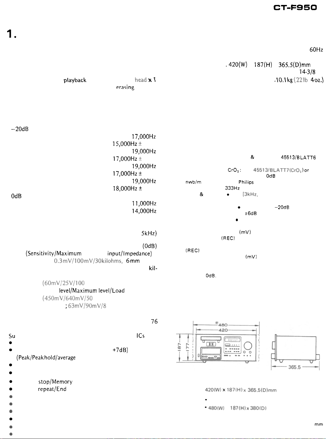
SPECIFICATION
CT-F950
Systems
Motors..
............
...........
Compact cassette, 2-channel stereo
Capstan drive; DC servo motor
Reel drive; DC high torque motor x 1
Heads
.........................
phyback combination
Ferrite recording/
type
head
Praqing head
Fast Winding Time.
Wow and Flutter
..........
.........
Approximately
85
seconds
(C
-
60 tape)
No more than 0.04% (WRMS)
Frequency Response
-20dB Recording
Standard, LH tapes
..............
20
to 17,000Hz
(25 to 15,000Hz * 3dB)
Ferrichrome tape
...............
Chromium dioxide tape
(25
...........
20 to 19,000Hz
to
17,000Hz 2 3dB)
20 to 19,000Hz
(25 to 17,000Hz t 3dB)
Metal tape
...................
.20 to 19,000Hz
(25 to 18,000Hz t 3dB)
OdB Recording
Chromium dioxide tape
Metal tape
Signal-to
...................
-
Noise Ratio. . Dolby NR OFF; More than 59dB
...........
20
to 11,000Hz
.20
to 14,000Hz
Dolby NR ON; More than 69dB
(over 5kHz)
Harmonic Distortion
.........
No more than 1.2% (OdB)
Inputs (Sensitivity/Maximum allowable input/lmpedance)
MIC (L, R); 0.3mV/100mV/30kilohms, 6mm diam.
jack (Reference MIC impedance; 250 ohms to 30
ohms)
LINE
x
2; (60mV/25V/100 kilohms) Pin jack
Outputs (Reference
x
LINE
2; (450mV/640mV/50 kilohms) Pin jack
HEADPHONES x
level/Maximum level/Load impedance)
1
;
63mV/90mV/8 ohms, 6mm diam.
jack
Semiconductors
.....................
Transistors x 76
Diodes x 84, Photo interrupter
Su bfunctions
ICS
Dolby NR system (ON-OFF) with LED indicator lamp
Fluorescent tube level meter
(-20
to +7dB)
(Peak/Peakhold/average selector)
Fluorescent tape counter
Bias fine adjusting control knob
Memory stop/Memory play
Counter repeat/End repeat
0
Input selector
0
Automatic tape slack canceller
0
Cassette compartment illumination
Standby mechanism with unattended recording
0
Tape Selector 4 position.
0
Click Stop. Output VR.
x
x
x
x
kil-
x
13
Power Requirements
1
1
1
Power Consumption
Dimensions
Weight
......
.........................
Furnished parts
................. AC 120V 60Hz
......................
.420(W) x 187(H) x 365.5(D)mm Max.
16
-
9/16 x 7-3/8 x 14-318 in.
.\O.\kg
Stereo connecting cords
Head cleaning swabs
Operating instructions x
.54 watts
{22\b
4ozz.)
with
pin plugs x
2
x
3
1
NOTE:
Specifications and the design subject to possible modifi
-
cation without notice due to improvements.
NOTES:
1. Reference Tapes: Standard
equiv.
:
2. Reference Recording Level: Meter
nwb/m magnetic level = Philips cassette reference level)
3. Reference Signal:
4. Wow
5.
6. Signal
7.
8.
9.
10.
81
Flutter:
(weighted), rms value]
Frequency Response: Measured at -20dB level, DOLBY
NR
OFF,
level deviation
to
Noise Ratio: 0 Measured at the third harmonic distor
tion 3% level, weighted.
Sensitivity: Input level (mV) required for reference recording
level with input
Maximum Allowable Input: While decreasing settings of input
(REC) level controls and increasing level at input jacks, this
the
maximum
amplifier output waveform becomes clipped.
Reference Output Level: Playback output level when meter
indicates
Maximum Output Level: Playback
reference recording level when
are
set
OdB.
to
maximum.
CrO,: DIN 45513/BLATT7(Cr02 )or equiv.
333Hz
(REC)
input
&
LH: DIN 45513/BLATT6 or
OdB indicating level (160
JIS
[BkHz, with acoustic compensation
is
26dB without indication.
controls set
level (mV) at the point where recording
to
maximum.
output
output
level with respect
(PLAY) level controls
-
is
to
1
420(W) x 187(H)x 365.5(D)mm Max.
with rackmount adaptor JA-R102
480(W) x 187(H)x 380(D)
mm
Max,
Unit:
mm
Page 4

2.
FRONT PANEL FACILITIES
@POWER SWITCH
The power comes on when the POWER switch
level meter and tape counter, and the cassette compartment
illumination will then come on.
is
depressed. The
@DUST COVER
When you are not using the deck, always keep this cover in place
to prevent dust and dirt from adhering to the head section and
rotating parts.
@REMAINING TAPE MARKER
If
this marker
ina for several minutes of recording or playback.
is
visible,
it
means that there
is
enough tape remain-
@INPUT (RECORDING LEVEL) CONTROLS
Use these to adjust
jacks or rear panel INPUT jacks.
Turning these controls to the right increases the level.
The controls are coupled to the left and right channels, but
you
can also
the left channel (front) independently.
the
level
of
the input signals from the
use
them to adjust the right channel (back) and
@OUTPUT (PLAYBACK LEVEL) CONTROLS
Use these to adjust the output signal level during playback. Turn
ing the controls to the right increases the level. The controls are
coupled when turned but it
channel (back) and the
When playing back
playback level
click stop position.
(OdB)
a
is
is
left
reference tape
obtained with these controls
also possible to adjust the right
channel (front) independently.
(160
nwb/m), a reference
set
to the
@TAPE SELECTOR
This selector allows the bias and equalizer characteristics to be
selected during recording and the equalizer characteristics during
playback in line with the type of tape you are using.
METAL: For using metal tapes
LH
STD:
CrO,: For using chrome tapes
Fe
For using ordinary or
-
Cr: For using ferrichrome tapes
tapes
@MlC JACKS
These are the input jacks for microphone recording. Plug the
channel microphone into the L jack and the right channel micro
phone into the R jack.
@HEADPHONES JACK
This is the output jack for your stereo headphones. You will
able to hear sound from signals selected by the MONITOR switch
es.
Use this jack when
recording or when
CT-FgSO. Adjust the output level with the
NOTES:
Use low-impedance headphones.
Y
O
model,
You
HEADPHONESjack by mistake.
U
will damage tht. microphone
BINPUT SELECTOR SWITCH
Use this switch to select the program source which you intend to
MIC
-
"6"
record.
LINE:
MIC:
NOTE:
LINE switch is depressed euen when the microphones are
plugged into the
Set
which
Set
phone, or microphones, connected to the MIC jacks.
You
will be able to record signals from the INPUT jacks
@DOLBY* NR SWITCH
Set
this switch to ON for recording with the built-in
reduction system and for the playback of tapes which have been
recorded using the Dolby
@BIAS CONTROL
Use this control to adjust the bias in accordance with the
characteristics of the tape being used.
(click stop) position corresponds to the standard bias.
@MONITOR SWITCHES
You will be able to listen to the recorded signals (playback sound)
if
you
depress the TAPE
left
You will be able to listen to the signals (recording input) just
before they are recorded if you depress the SOURCE. Use these
switches to monitor your recording. Depress the TAPE during
-
play back.
you
want to monitor the quality
want to listen to a tape privately on the
you
OUTPUT
If
you
will not be able to obtain sufficient volume.
to this position for recording a program source
is
connected to the rear panel INPUT jacks.
to this position for recording signals from a micro
MIC
jacks.
NR
system.
while you are recording a program.
use a high-impedance
if
you
It
is
plug
set
so
that the center
controls.
it
into the
Dolby
of
if
the
noise
be
-
a
-
*Manufactured under license from Dolby Laboratories.
OD
*Dolby and
are trademarks
of
Dolby Ldboratorie5.
Page 5

CT-FS50
I
1
3-HEAD
I
CLOSED
2
LOOPDUAL CAPSTAN
MOTOR TAPE TRANSPORT
L
SYSTEM
@OPE RAT1 NG SWITCH ES
II
(REW):
W
(FF):
I
(STOP):
b
(PLAY):
REC:
PAUSE
:
NOTES’
When any
responding indicator (except
signifying that the deck is set to that respective mode.
*All
the operating switches are released
when the
Depress this switch to rewind the tape. (The tape
will travel at high speed from right to left.)
Depress this switch to send the tape forward at
high speed. (The tape will travel from left to
right.)
Depress this switch to stop the tape run and to
release
the operating switches.
Depress this switch when playing back
(The tape will travel from left to right.)
Depress this switch together with the PLAY
switch for recording.
This switch will not
loaded or when the erasure prevention tabs of
loaded cassette have been broken off.
Depress this switch to stop the tape temporarily
during recording or playback.
allow the tape
of
the operating switches ore depressed. the cor
POWER
switch
is
work when a cassette
tc continue to travel
STOP
turned
OFF.
Depres5 it again to
mode) will come
(OFF)
as
to
@COUNTER RESET BUTTON
Depress this button to reset the tape counter display to
Q
TAPE
COUNTER
This indicates the position
“000”
when the power is switched on.
of
the tape run. The counter reset to
@LEVEL METER
This indicates the input level during recording and the output level
during playback.
By
operating the METER switches, it can be made to function
as a peak meter, a peak hold meter or as a level meter.
The input signal level
SOURCE has been depressed, and the
indicated when the MONITOR switch TAPE has been depressed.
@DOLBY
This lights up when the DOLBY NR switch
indicates that a tape
Dolby NR system.
NR
is
indicated when the MONITOR switch
playback‘output level
INDICATOR
is
being recorded or played back with the
is
set to
@TAPE INDICATORS
METAL: This light comes on when the TAPE selector is
CrO,: This light comes on when the TAPE selector is
METAL.
CrO,.
7
a
tape.
is
not
before.
on
stop mode
“000.”
ON
and it
set
to
set
to
@+-\I
s
.....
...............
0
@
MEMORY/REPEAT INDICATOR
This indicator comes on when the MEMORY/REPEAT switches
are
depressed, signifying that the deck
mode.
@MEMORY/REPEAT SWITCHES
:
MEMORY
a
REPEAT
COUNTER:
-
@METER SWITCHES
PEAK:
PEAK
AVERAGE:
@TIMER START SWITCHES
Depress these switches when
tape with the use of a timer.
REC:
is
PLAY:
OFF:
Depress this switch and the tape will be rewound to
STOP
that spot at which the tape counter was preset to
“000”
during rec/play, when the REW switch
depressed at any position
PLAY:
Depress this switch and the tape will be rewound to
that spot at which the tape counter was preset to
“000”
during rec/play, and playback will start from
that spot, when
position
tape during playback or recording from the point
end of the tape.
END:
OFF:
recording to release the MEMORY and REPEAT
switches.
HOLD:
When this switch is depressed, the deck will autom2tical-
ly
be
and recording will begin, Use
FM programs when
wise occupied.
When this switch
ly
be
and playback will begin. Use this switch for wake
playback instead of an alarm clock.
Always depress
record or playback
release the REC and PLAY switches of TIMER
START.)
you
like.
Depress this switch when
which the tape counter was
Depress this switch when
tape from the beginning to the end of that tape.
Depress this switch during normal tape playback or
The meter functions
this switch is depressed.
The meter functions as a peak level meter and
the highest level of
this switch
The meter functions
switch
set
to the recording mode at the preset timer time,
set
to the playback mode at the preset timer time,
is
is
depressed.
is
depressed, the deck will automatical
this
............
I!)
0
is
set
to the respective
you
like.
the
REW switch
as
the
depressed.
you
as
are playing back or recording
you
are
switch when
a
tape using the timer. (This will
is
depressed at any
you
want to play back
set
to
“000”
up to the
you
want to play back
a peak level meter when
signals
is
indicated when
a level meter when this
this
switch for recording
out
of the house or other
you
do not intend to
is
a
at
a
a
-
-
-
up
Page 6

3.
LEVEL
PLAYBACK
DIAGRAM
-60-
-80-
-?4dBV
(0.2mV)
-36dBV
PB AMP Gain
49dB
1
VR Loss
I
IdB
Note;
.
OdBV=IV
. Frequency
:
333Hz
Page 7

RECORDING
MIC
!I?
-
20
I
I
I
I
I
I
I
LINE
MIC
IICAMP
A
6
I
VR
1201-1
I
>
m
0
-
J
W
>
W
J
-
-
-
0
20
40
60
-
I
i
IOdBV
(0.31V)
-
'R
Max.
-245
dBV
59.5rnk
60dBV
IrnV)
-
?OdE\r
0.32mk
I
I
I
I
-32dBV (25.lmV)I
VR
Max.
.42dBV -42dBv
(7.9 m V) (7.9 m\
MIC
28
I
I
I
I
I
I
I
I
I
I
I
__
AMP Gain
dB
I
!R
Max.
-
7dBV
(
0.4
LINE AMP Goin
40dE
VR
Loss
I
OdB
DOLBY iMP
4
V)
Gain
4dB
VRLasr
2368
I
I
I
-26dBV
(50.lrnV)
I2.dB
1
OdBV= IV
Frequency
:
333Hx
Page 8

4.
DISASSEMBLY
External
1,
Remove the bonnet by undoing screws 0 to
2.
Remove the front. panel by undoing screws
@to
3.
Remove the bottom plate by undoing screws
CD
CD.
to
Components
a$.
0.
4.
The function switch assembly is mounted onto
the chassis by means of rubber bushes. Remove
it by gently raising it up.
Fig.
4-1
Disassembly
of
exterior parts
i
Q
Page 9

CT-FS
5
0
Mechanical Assembly
After removing the front panel, undo screws
OtoO.
0
Fig.
Sub-head Assembly, Pinch-roller Arm Assembly
and Pressure Arm
1.
Remove the sub-head base assembly by undoing
screws
bolt.
2.
Remove the feed side pinch-roller arm assembly
by loosening the height adjuster (unt).
3.
Remove the take-up side pinch-roller arm
assembly by taking off E
4.
Remove the pressure arm by taking
0
When the pinch pressure spring is replaced
with a new one, take care to ensure that the
Remove the mechanism assembly
4-2
0
and @ and the socket-head hexagonal
-
washer
0.
off E-
washer
new spring
of the sub
adjustments” (Page
is
properly seated. The requirements
-
section entitled “Pinch roller pressure
30)
included in the section
“Mechanical adjustments” shall be satisfied.
Fluorescent Indicator Tube
1.
Remove the indicator lens assembly by undoing
screwsOtoO.
2.
Remove the indicator amplifier assembly by
8
to
undoing screws
3.
The fluorescent indicator tube is mounted on
@.
the indicator assembly. Remove it by means of
a soldering iron.
the indicator tube
Indicator assembly
Fig.
Remove the fluorescent indicator tube
4-3
Take great care when handling
so
as
to avoid damaging it.
n
Indicator amplifier assembly
Indicator lens assembly
I
Pinch-roller arm assembly
B
Height adjuster (nut)
Socket
Remove the sub-head assembly, pinch-roller arm assembly and pressure arm
4-4
Fig.
-
head
P
Pinch
-
roller arm assembly
Page 10

Mechanical
Assembly
When replacing a motor or a belt, be careful
the sequence of disassembly and reassembly
various components concerned.
1.
Remove the capstan motor by undoing screws
\Oto
0.
2.
Remove solenoid A by undoing screws
0
to
of
of
the
0.
3.
Remove the plunger chassis assembly by undoing
@to
screws
4.
Remove the sub-chassis assembly by undoing
screws
5.
Remove the take-up motor by undoing screws
CD
and
screws
Sub-chassis assembly
Q).
CD
to
@.
(D,
and remove solenoid B by undoing
@
and
@.
UL
cord clamper
Fig.
4-5
D
Disassembly
of
mechanism assembly
Supply pulley assembly
 Loading...