

Page 1
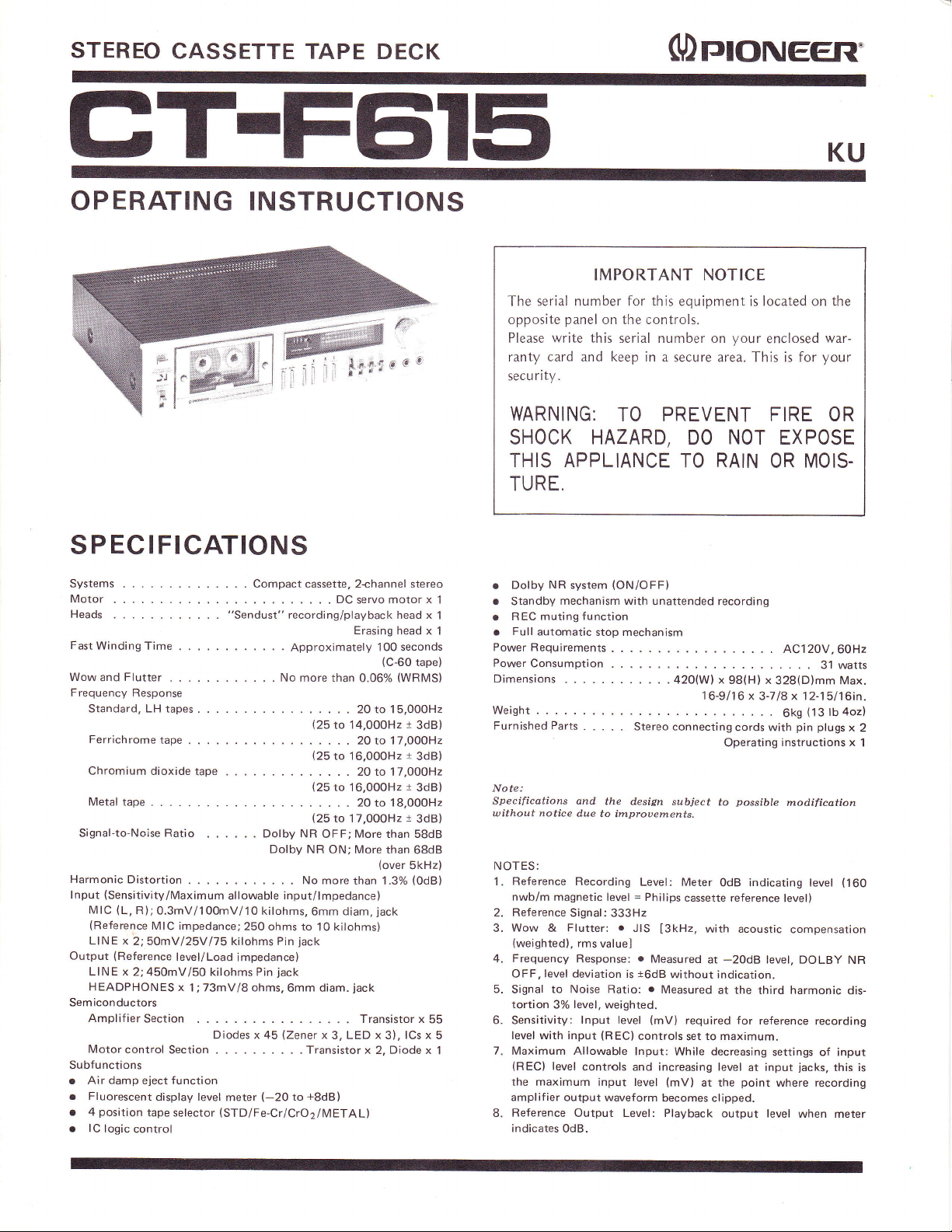
STEREO
CASSETTE
TAPE DECK
()rqoNEER'
GT-FEil5
OPERATING INSTRUCTIONS
The serial number for this equipment is located on the
opposite
Please write this
ranty card and keep in
ri ty .
secu
WARNING:
SHOCK
THIS APPLIANCE
TURE.
P EC IFICATIONS
S
Systems
Motor
Heads
Fast
Winding Time
Wow and
Frequency
Flutter
Response
Standard,LHtapes
Ferrichrometape.
Chromium dioxide
Metal
tape
Signal-to-Noise
Harmonic
lnput
Output
Sem
Subfunctions
Distortion
(Sensitivity/Maximum
(L,
MIC
(Reference
LINE x
LINE x
HEADPHONES
Amplifier
Motor
R);0.3mV/100mV/10
2;50mV/25Vl75 kilohms Pin
(Reference
2;450mVl5O kilohms Pin
iconductors
control
Section
tape
Ratio
MIC impedance;250
level/Load
x
1;73mV/8 ohms,6mm
Section . Transistor
r Air damp eject function
o Fluorescent
position
. 4
r lC
logic
control
tape selector
display
level
Compact cassette, 2.channel stereo
"Sendust"
recording/playback head x
No more
.
Dcservomotorx
. . . . .
Approximately
than 0.06%
.....29to15,00OH2
(25
to
....2lto17,O00H2
(25
to 16,000H2
. . 20 to 17,000H2
(25
to 16,000H2
....2Oto18,000H2
(25
Dolby NR
Dolby NR
allowable
Diodes x 45
meter
(STD/Fe-Cr/CrO2lMETALI
input/lmpedance)
kilohms,6mm
ohms to
impedance)
jack
(Zener
(-20
to 17,000H2
OFF; More than 58dB
ON;
No more
diam,
kilohms)
10
jack
diam.
x
3, LED x 3),
+8dB)
to
Erasing
100 seconds
{C-60
14,000H2
More
than
(over
than 1.3%
jack
.jack
Transistor x
x 2. Diode x
head x
tape}
(WRMS)
t
3dB)
t
3dB)
t
3dB)
t
3dB)
68dB
5kHz)
(OdB)
lCs x
55
Dolby
1
1
1
o
. Standby
REC muting
o
Full
r
PowerRequirements.
Power
Consumption
Dimensions
Weight .
Furnished
Note:
Specifications and
without notice
NOTES:
Reference
1.
nwb/m magnetic
2. Reference
Wow
3.
(weighted),
4. Frequency
OFF,
5.
Signal
tortion
6. Sensitivity:
5
1
level with input
7. Maximum Allowable
(REC)
the maximum input level
amplif
Reference
8.
indicates
IMPORTANT NOTICE
panel
on the controls.
serial number on
TO PREVENT FIRE OR
HAZARD,
NR
mechanism with
automatic
Parts
&
level deviation
to Noise Ratio:
3%
level
ier
output
0dB.
(ON/OFF)
system
function
stop mechanism
.
the design
due to
improuements.
Recording
level = Philips
Signal: 333H2
Flutter:
r
rms
valuel
Response:
level,
Output Level: Playback
is
weighted.
lnput level
(REC)
controls
waveform
your
a secure area. This is for
NOT
DO
RAIN
TO
unattended recording
..... AC120V,60Hz
420(W) x
Stereo connecting
subject
Level:
Meter
JIS
[3kHz,
o
Measured
t6dB
without indication.
r
Measured
(mV)
controls
lnput: While
and increasing level
(mV)
becomes clipped.
98(H) x
1
6-9/16 x 3-718 x 12-15116in.
cords with
Operating
possible
to
OdB indicating level
cassette reference
with acoustic
at
-2OdB
at the third harmonic
required for
to maximum.
set
decreasing
at input
point
at the
output
KU
enclosed
OR MOIS-
328(D)mm Max.
level,
reference
settings of input
where recording
level when meter
war-
your
EXPOSE
31 watts
(13
tb
6kS
pin
plugs
instructions x
modification
level)
compensation
DOLBY NR
recording
jacks,
this is
4oz)
x
(160
dis-
2
1
Page 2
SAFETY
INSTRUCTIONS
READ
structions
operated.
RETAIN
structions should be
HEED WARNING
and in the operating
ed to.
FOLLOW INSTRUCTIONS
use instructions should be
WATER AND MOISTURE
not be
bathtub, washbowl, kitchen
a wet
LOCATION
a
WALL
should not be mounted to a wall or ceiling.
VENTILATION
ed so that its location or
fere
appliance
rug,
tion
such as a bookcase or cabinet
the
HEAT
from
stoves, or other appliances
that
POWER
connected
scribed
on the appliance.
INSTRUCTIONS
should
INSTRUCTIONS
be read before the appliance is
retained for future reference.
All warnings
-
instructions
All the
-
-
-
followed.
The appliance should
-
near water
used
basement, or
stable
location.
OR CEILING
with its
-
should
near
The
appliance should be
MOUNTING - The appliance
The appliance should
-
proper
ventilation. For
not
be situated on a
or similar surface that may block
through
heat.
power
placed
-
supply only of the type de-
openings; or,
flow
of air
The appliance should be
-
heat
sources such as
produce
SOURCES
to a
in
the operating
for
-
sink,
a swimming
position
in
a built-in
the ventilation openings.
radiators,
(including
The
appliance should be
instructions
operating
The operating in-
the appliance
on
should
All operating and
example,
laundry tub, in
pool,
does not inter-
example, the
that may impede
situated
heat
or as marked
in-
be adher-
near a
etc.
installed in
be
situat-
bed,
sofa,
the ventila-
installation,
away
registers,
amplif
iers)
POWER-CORD
cords should be routed
be walked
to
or against them,
plugs,
at
cords
point
where
CLEANING - The
with a
only
Never
clean with furniture
or other
des
rode the
NONUSE
pliance
when
OBJECT
taken so that objects
not spilled
cabinet.
PERIODS
should be unplugged from
left
AND LIOUID ENTRY
DAMAGE REOUIRING
ance should be serviced
service
when:
The
o
damaged; or
center or
power-supply
o Objects
the
into
PROTECTION
to
pinched
on
or
paying particular
convenience receptacles,
they
polishing
volatile liquids
unused for
into
have fallen,
appliance;
from
exit
appliance
cloth or a
The
-
a long
do not
the enclosure through
qualified
cord or the
or liquid has
or
that they
by items
the
appliance.
should be
wax, benzine, insectici-
since
power
period
fall
SERVICE
Pioneer
by
service
r The appliance has been exposed
r The appliance does not
mally or
ance; or
The appliance
r
closure damaged.
SERVICING
service
operating
be contact nearest Pioneer
center.
exhibits a marked
has been dropped,
The
-
the appliance
instructions. All
appear to operate nor-
change in
user should not attempt
beyond
that described in the
other
authorized
Power-supply
are not likely
placed
attention to
and the
cleaned
dry
soft
cloth.
they may cor-
of the
cord
the outlet
of time.
Care should be
-
and liquids are
openings.
The appli-
-
authorized
personnel
plug
has been
been spilled
rain;
to
or
perform-
or the en-
servicing should
service
upon
ap-
to
Page 3
PIONEER
OPERATING
When
(amplifier,
cord
cords
this
stereo recordings
microphone.
The
(PHONES)
the
phones.
The
be
chrome
tapes.
playback
The Dolbyx
out a
high-frequency
sound
10dB
range).
and makes
sources with
The deck
function
for
sound
usual
hooked up to
tuner, turntable, etc.),
play
and
and other
deck. In
back
program
addition,
using
deck is
recording or
provided
jack,
and this allows
tape
tape selector buttons
given
to the characteristics of metal
tapes, ferrichrome
They can
with
great
also be used
the bare
noise
reduction
deal of that irritating
range
qualit5r
improvement
of the
This system
possible
it
a high signal-to-noise
comes with
which can be
unattended
of a tape
alarm clock-
recording
being
THE CT-F61 5
your
stereo components
you
can re-
FM or AM
you
an electret or
with a headphones
play
permit
minimum
without
program
in
the high frequency
expands the
to record
an unattended
used along
played
broadcasts,
sources in
can make
stereo
your
dynamic
you
to monitor
with
stereo head-
justice
full
tapes and
for
standard
recording
of
distortion.
system serves to cut
tape
hiss in the
sacrificing
source
(it yields
dynamic range
play
and
ratio.
recording
with the timer
and
wake-up
back instead
re-
on
own
to
tapes,
and
the
sound
back
to the
of the
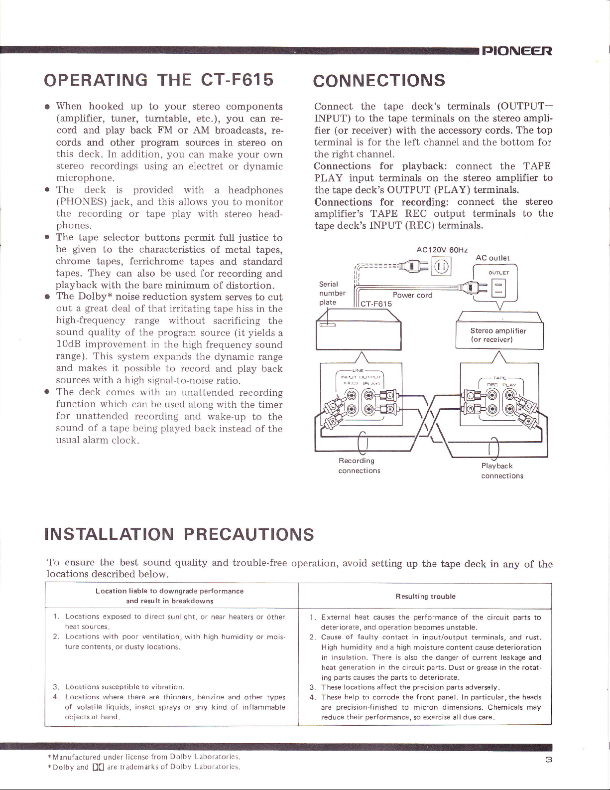
CONNECTIONS
Connect
INPUT)
fier
terminal
the
Connections
PLAY input terminals
the tape deck's
Connections
amplifier's TAPE
tape
Serial
number
plate
a
the tape deck's terminals
to
the tape terminals
(or
receiver)
is for
with the accessory
left channel
the
right channel.
playback:
for
on the stereo
OUTPUT
for recording:
REC output terminals to
deck's INPUT
..-...-
_LINE
r ,-*,- .,,,",,-)
| "=' r"' I
I
z'a\ z-a\
)ie)ltgE
(REC)
AC120V
-
on
and the bottom for
connect
(PLAY)
connect
terminals.
60Hz
Wdt@+
(OUTPUT-
the stereo
cords.
The
the
amplifier
terminals.
the
AC outlet
Stereo amplifier
(or
receiver)
I *.- oo, ]
-TAP€_
hq@J
tr@@s
ampli-
top
TAPE
to
stereo
the
INSTALLATION
To ensure
locations
Locations
heat sources.
Locations
2.
ture contents, or dusty locations.
2
Locations susceptible
Locations where there are thinners, benzine
4.
the best sound
described below.
exposed
poo:"
with
liable
result in
and
to direct
ventilation,
to
Location
of volatile liquids, insect sprays or
objects at hand.
*Manufactured
x
Dolby
and
under license
are
D0
trademarks of
quality
to
downgrade
breakdowns
sunlight, or near heaters or
vibration.
Dolby Laboratories.
from
Dolby Laboratories.
P
RECAUTIONS
and
trouble-free
performance
dther
with high humidity or
and other types
kind
any
of inf lammable
mois-
operation, avoid setting
Resulting trouble
1. External
deteriorate,
2. Cause
High
in insulation. There is also the danger of current leakage and
heat
ing
3. These
4. These
are
reduce
heat
causes
and operation
faulty
of
humidity
generation
parts
locations affect the
help to corrode the
precision-f
their
contact
and
in the
causes the
inished
performance,
a high
parts
up
the
tape deck in
performance
the
becomes unstable.
in input/output terminals,
moisture content cause deterioration
parts.
circuit
to deteriorate.
precision parts
front
to micron dimensions.
exercise
so
Dust
panel.
all
of the circuit
grease
or
adversely.
ln
due
in the rotat-
particular,the
Chemicals
care.
any
parts
and
of the
to
rust.
heads
may
Page 4
FRONT
PANEL
FACILITIES
powrn
e
Power is supplied to
the level meter lights up.
turn OFF the
To
rlmEn srART
@
This is
unattended recording
REC:
OFF: Set
PLAY: Set to this
CASSETTE HoLDER/EJEcT
@
cassette
The
the E.IECT
back until
REMAINTNG
@
lf this
for several
ing
swtrcH
the deck when
power,
set it to bottom
swlTCH
when the
used
to
Set
recording
to
start
stance.
to this
ing.
playback
start the
used to wake
clock.
tapes are
button
locks.
it
marker
timer
wake
and
position
this
mode
at the
the recording
position
position
at
mode
playback.
up in
loaded into this holder. lt
is depressed. To close the holder,
TAPE MARKER
is visible, it means that there is
of recording or
minutes
employed
is
up
to
for normal tape
to
the time
The
the morning
this switch is set
position.
along
playback.
deck
set the
preset
time
programs
of
deck automatically
set the
preset
playback
tape
playback.
ON,
to
with the
automatically
on the
unattended,
playback
deck
timer
and
to the
for in-
record-
to
on the
function
instead
can be
of an alarm
and to
timer
BUTTON
jumps
out when
push
the top
enough tape remain-
and
for
and
the
LEVEL METERS
@
indicate
These
during
level
rrupur
@
these
Use
jacks
or rear
Turning these controls to the right increases the |evel, For further
derails,
9. The
can also use them to adjust the right
channel
HeRopHoNE
@
is
This
phones
recording
NO?ES:
.
Use
model,
.
You
by mistake.
rvrc
@
These are
channel microphone
phone
into the R
the
playback.
(REcoRDTNG
to adjust the
panel
LINE-lNPUT.
refer
to
controls are
into this
"SETTING
(front)
independently.
output
the
jack
when
you
you
will
or
lou-impedance
uill damage
IAcKS
the
input
iack.
input level during
of the input
level
THE RECORDING LEVEL" on
coupled
to
the left and
JAcK
jack
for stereo headphones. Plug
you
when
to
listen to a tape
want
head.phones.
not
be able to obtain
the microphone if
jacks
for
into
microphone
!he L
recording and the
LEVEL)
want to monitor the
If
jack
and the right
coNTRoLS
signals
right
channels,
(back)
channel
privately.
you
a
use
high-impedance
sufficient uolume.
you plug
recording. Plug the left
output
from
the MIC
but
and the left
your
head-
quality
it into this
channel micro-
page
you
of a
jach
couNrER RESET
@
COUNTER
Depress this button
Tape counter
indicates
4
BUTToN/TAPE
to reset the tape
the
position
of the tape
counter
display
run.
to
"000."
REC MUTE SWTTCH
@
For details,
page
9.
(ON
during recording
)
refer to
"USlNG
While this switch is depressed
kept depressed), blanks can be recorded on the tape since
put
signals are
REC
MUTE
not
recorded.
SWITCH"
on
(switch
the in-
THE
is
Page 5

TJIONEER
DoLBY
O
Set this
reduction
recorded
Dolby
NR
i nstru
cti o ns.
UPE SELECTOR
@
This selector allows the bias
selected
playback
refer ro
position:
STD
position:
Fe-Cr
position:
HIGH
I
I
I
cror; For using
f
L
rvtetnt;
oPeRITING SWITcHES
@
(REWI
<<
(FF):
>>
(Stop):
I
REC:
PAUSE:
NOTE:
. The
tions even
NR
swtrcH
switch
system
using
system, refer to
during recording and the
in line with the type
"LISTING
: Depress
operating
for
to ON
for
and
Dolby
the
OF TAPES" on
For using
For using ferrichrome
Set to this
tapes
and
or METAL.
For using metal
speed. (The
Depress
high
Depress
release
tape
Depress
switch
This
loaded
loaded
Depress
during
switch
this
this switch to
speed.
this switch to
the operating
travel flom
will
this switch
for
switch will
or when the erasure
cassette
this
recording or
to allow the tape
switches will not
when
the
recording
the
NR
the leaflet
standard or LH
position
then
chrome tapes
tape
(The
recording.
pouer
with
playback
system.
and equalizer characteristics
of
set the
tapes
switch to rewind the
will travel
tape
not work when a
have been broken off-
switch to stop
is
the built-in Dolby
of
tapes which have
For
further
inserted
equalizer characteristics during
you
tape
page
suitched OFF.
are using. For details,
7.
tapes
tapes
when using chrome or
right-hand
from
send the
will travel from
stop the tape run and to
switches.
left
to right.)
together with
prevention
the tape temporarily
playback.
to continue to travel.
return
to their original
noise
details on the
into the operating
been
to
metal
switch to
right to left.)
tape
cassette is not
Depress
CrO2
tape
at
forward
Ieft to right.)
> (Play)
the
tabs of a
> (Play)
high
posi
CHECK
Slack
If
Fig.
passing
roller and so
by inserting a
tuming
be
Some
slack.
before
at
Erasure
Cassette tapes
tabs,
device to
recording
the
you
tally
depressing
To re-record, cover
layer
NOTE:
Cassette tape
2) so
CASSETTE
protruding
or
the tape
A
or
through
it
tapes
Make
inserting
prevention
shown
as
tabs,
be
will
set
the tape
of adhesive
you
can
prptrudes
is
slack,
between
may
pencil
indicated
as
provide
sure
that
the
pencil
Turn
remove
tape
are
in Fig.
prevent
which
as shown
you
able to
the REC
prouided
are
protect
BEFORE
tapes
from
the cassette
the
tape
the
be damaged.
through
in
the figure.
a tape
you
stopper
remove
tape into
to
slack.
tabs
provided
the
with
B,
which
accidental
want to
in
Fig. B,
prevent
deck
to the recording
switch.
the tab
tape
the recordings
opening
(Fig.
with two
USE
may
capstan
Take
the reel
the deck.
erasure
act
keep. If
with
erasure
C).
tabs
on both
as shown
run
without
and
the
up
the slack
hub and
prevent
to
the
tape stopper
Fig. A
prevention
protection
as a
erasure
you
remove
a screwdriver
you
if
acciden-
mode by
with a double
(A
or
I and
sides.
pinch
tape
of a
B
in
or
erasure
Side A
prevention
tab
Fig.
B
/
-Side
prevention
B erasure
tab
Fig. C
5
Page 6

BASIC
OPERATION
J
"!.
""s==
LOADING
AND UNLOADING THE
Tape loading
1. Depress
springs
the
forward.
2. Load the cassette with
at
bottom.
the
corded
or
EJECT
played
TAPE
button until the cassete holder
Cassete
the exposed end
The side
(A
back faces
or
you.
B)
which
holder
of the tape
is to be re-
."m.fl
Play
1. Check
The
2.
when
pressed.
depressed together with the
set
Fast forward
1.
Check
The tape
2.
Rewind
1. Check
2.
record
and
the tape is on the
that
reel.
tape runs
the
from left to right
(PlaY)
>
lf the REC
(Play)
>
to the recording mode.
that the tape
reel
.
high
at
switch
forward
reel.
The
at
switch
is
speed
is depressed
operation.
that the tape is on the right
tape
high speed when the
is depressed,
rewound.
the deck
switch,
from
runs
when the
runs from right to left
switch
switch
is
on
left to
for
and the tape
Fast
is
will
the left
a
<<
left
de-
is
also
right
)>FF
fast
REW
forward
be
fl
flrow
Play
Irr+
Play, Record,
Fast foward
PAUSE
NOTE:
The
cassette
serted
it
since
Push
3.
you
hear
Unloading
the
As for loading
and this will open the cassette holder.
tape can not
aduersely.
causes
the cassette
Do not insert the
the breakdowns.
holder
click that denotes the holder
a
tape
the tape, depress
tape out. Do not depress
the tape is
still
traveling.
be
loaded
back into
the
EJECT
the
it is in-
when
tape
forcibly
position
EJECT button
until
is locked.
Now take the
button while
STOP
Stopping the
Depress the
Using
1.
2.
The
o
r
OPERATION
tape
(Stop)
r
Pause
the
The tape
the tape
When the
ing
NO?ES:
1. When stopping
2.
is traveling
(recording
again
(StoP)
I
When
using
mind that
place
at the
mod,e.
PAUSE
switch comes
the recording level is
When
you
When
recording and then continue recording.
will
stop
(Play)
>
switch.
a
the
on the tape
want to
Switch
the tape
pre-recorded
pre-recorded
to stop the tape
switch
when
(recording
switch is depressed, the tape willstart travel-
or
edit
PAUSE
the
or
playback).
prolonged
a
for
tape to re-record a
sound
where
in
handy in the
set.
out some
switch
playback).
will
you
set the dech to the PAUSE
f
portions
AUTO.STOP MECHANISM
When the tape is fully rewound
reels during
rewind,
without
and the
several
The
the auto-stop mechanism is activated
the
tape
seconds later.
power
mechanism
recording,
(Stop)
r
will
does not
is activated.
playback,
switch
having to be depressed,
automatically come'to
go
off when
travel.
is depressed
period
sometimes not be
ollowing instances:
onto
of
program,
program
of a
one of the
time,
fast forward
the auto-stop
while
use the
bear in
erased
during
or
a halt
6
Page 7

PIONEER
CASSETTE
Cassette
national
and they are
tape
Performance
Standard type
o
.
Recording
The size
playing
the
tapes are manufactured
standards
generally
performance
Standard
Dynamic
tape
tape
and recording
classif ications
Low-noise type H igh-performance type
.
Low-noise
r
Low-noise, high-
output
time classifications
designati o
c-30
c-46
c-60
c-90
c-120
tape
n
Cassette
of the cassette
(and
recording)
tape thickness
(length).
TAPES
according
governing
classified
tape
Recording
One side Both sides
15
aa
30
45
60
tapes is the
their construction,
according to their
time.
tape
times differ
.
Chrome
.
Ferrichrome
Metal tape
.
time
(minutes)
same
according to
to
tape
tape
30
46
60
90
120
but their
inter-
The C-60
The
their mechanical
HINTS
o
Check the tape
Before starting
load
and C-90
C-120
ON
the tape
tapes
tapes
are not
and electrical
HANDLING
before recording
to use
and set the
forward and rewind. This
from damage caused
winding.
o
Take care with
A leader
cassette tape
about 5
point
this
o
Do not load
ing the heads
Do not load
cleaned
have
completely
are
'seconds
the
tape is attached
(you
for
in
mind
a cassette immediately
a cassette immediately
the
dry
are most commonly
recommended
specifications
CASSETTE TAPES
the tape for
tape
safeguard the
will
irregularities
by
leader
tape
to the beginning of
cannot
when
heads until
(this
record on it). It takes
pass
it to
through, so bear
recording.
the
takes 2-3
because
recording,
to fast
deck
in
the
after clean-
after
head
surfaces
minutes).
used.
vary.
deck
tape
the
you
LISTING
This
table shows the
BASF
AGFA
scoTcH
TDK
AMPEX
OF' TAPES
proper
settings
position
STD
LH
C-60
LH C-90
LN C-60
LN C-gO
LH
SUPER C-60. C-90
sLH-r
c-50
sLH-r c-90
LH
C-60
LH C-90
SUPER HIGH DYNAMIC
c-60 +6
SUPER HIGH
LH
LH
CRYSTAL
CRYSTAL
M- t2
M- t2
D C-60,
sD c-50
sD c-90
ED C-60
ED C-90
AD C-60
AD
C-90
STUDIO OUALITY
PLUS
PLUS SERIES C.9C)
DYNAMIC
c-90 +6
C-60
c-90
C-6O
C.90
c-60
c-90
C-90
SERIES
C-5C
C.6C
of the tape selector
for
standard
MAXELL
FUJI
tape
LN C-60
LN
uD c-60. c-90
uL c-60
uL c-90
UD XLI C-6O
xL I
xL I
FM C-60
FM C-90
FL
FL C-90
FX
FX C-90
FX
FX Jr C-gO
FX DUO C-5O
FX DUO
FX-r
FX-r
LN
LN
SONY
DENON
HF
AHF C-6O
AHF C.gO
BHF
DX-3 C-60
DX-3
for
all
C-90
C-60
C-90
C-60
C-60
Jr C-6O
C-90
C-50
C-90
C-60
C-90
C-60,
C-60. C-90
C-90
leading
C-90
brands of tapes.
position
CrO2
FUJI
SONY
PHILIPS
BASF
scoTcH M-7 C-60. C-90
f
or chrome
FC
FC
FX.I]
CR
CR
JHF
cRo 2
cRo 2
CHROMDIOXID C-60
CHROMDIOXID C.90
scR c-60, c-90
KR C-60.
sA c-60
TDK
MAXELL UDXL II
sA c-90
New
SA C'6O
New SA C-gO
lcR
UDXL II
XL II
xr- rr
I
tape Fe-Cr
c-60
c-90
c-50
c-60
c-90
c-60, c-90
c-60
c-90
C-90
c-60. c-90
c-60
c-90
c-60
c-90
position
SONY
BASF
scorcH
DENON
METAL
SCOTCH
SONY
TDK
FUJI
for ferrichrome
DUAD
New
FERROCHROM
FERROCHROM C.90
FCR
C-60, C-90
DUAD C-6O, C-gO
C-60
FCR C-90
CLASSTC
cLASStC C-90
DX-s
position
METAFINE
METALIC
c-46
MA C-46. C-50
SUPER RANGE
c-46
c-46
C-60
C-60. C-90
metal
for
tape
C.60
lape
Page 8

PLAYBACK
you
the
Set
switches and controls
o Set the
TIMER
as follows
START switch
before
to OFF.
switch
o Depress the COUNTER RESET button and
will be reset to
o Check that the
(Refer
to
Switch the amplifier
o
(Ex.
When
component
tion and
OPERATING PROCEDURE
the
Set
c
Load the cassette
@
Check
the side
and check that
load
the lape
Set the
@
Set the selector
tape to be used.
page
on
the DOLBY NR switch
Set
@
Set this switch
corded by the Dolby NR system.
"000".
head
page
section
11).
on
amplifier 5.4'-610
using
part,
TAPE-2
POWER
(refer
TAPE SELECTORS
7.
function switch to
set
switch to "OFF".)
switch
tape
to
page
which is to be
6).
position
playing
of the tape
the tape is wound on the
to the
For derails,
to ON when
is not dirty. If dirty,
enable tape
to
or
"TAPE"
ON
to
played
left-hand
corresponding
"LlsTlNG
to
refer
tape, which
back a
power
the
the counter
clean it
playback.
back
(A
reel.
as a
posi-
or B)
SA'710
to the type of
TAPES"
oF
was re-
Now
on.
Start
o
Depress tfre
Adjust the
volume
Complete
CD
When the
back, the
press
during
stop.
playback
(Playl
>
volume to the
control
on the
swiich and
stereo amplifier.
playback
tape is fully wound onto
(Play)
>
r
the
playback.
(Stop)
Depress the
switch
switch
the tape will start
preferred
the right reel during
released
will be
you
if
want to stop
PAUSE
level by rotating
automatically.
the tape
for
switch
a temporary
to run.
the
play-
De-
run
Follow
are illustrated in
playback
the
lPlayback )
the
and
figure.
-r-
recording
I=
IJII
procedure
below in numerical order.
The step
numbers
a
Page 9

TJIONEER
RECORDING
the switches
Set
o
Set the TIMER
o
Set the INPUT
o Inspect
page
to
.
Set up the
microphone performance,
record-
OPERATING
Set
O
Load
O
Check
securely.
cassette
Set
@
Set the
tape to
on
Set the DOLBY
o
Set this
tem-
o
Recording
Depress
PAUSE
to
about
ing
Depress
Set
@
Refer
ING LEVEL",
Starting
o
Depress
the
during
mount
Complete
o
When
and stop
stop. When
recording,
and controls as follows before
START
controls
the head
11).
the POWER
section for
program
PROCEDURE
the cassette tape
that the tape is
Also
check that the erasure
tape have not
the
TAPE
selector
be used. For
page
7.
switch to
the
indicators
the actual
10
seconds
PAUSE
the
the
"Leader
SELECTORS
to the
ON
standby
PAUSE
and
both light. When
cassette
to allow
and REC
counter reset
tape": This
the recording
to following
the
recording
recording
of tape left.
and
the
recording
>
begins.
the section
then
(Play)
to
check
recording
you
have finished
the tape.
the recording
Depress the PAUSE
the tape is
switch to OFF.
to the leftmost
dirt. If dirty, clean it
source
(records,
etc.)
which
switch to ON
wound onto the left
been broken off
position
details, refer
corresponding
to
NR switch
for
recording
REC
tape, depress
it to clear
swirches.
button
is
beginning
cannot
be
level
adjust the INPUT
switch. The
Observe
the recording
recording,
fully
wound onto
mode
using
switches
a leader
the
the heads
and reset
a section
and end
recorded.
INPUT
"SETTING
on
tape now
the level
depress
will be
automatically released.
you
switch the
position (0).
FM
broadcast,
you
intend
prevention
(see
"LlsTlNG
together. The REC
reel, and
page
5).
to the type
the Dolby NR
tape
(Play)
>
before depress-
"000".
to
of the
tape at the
of the
tape which
tabs
oF
is
switch
TApEs,,
attached
controls
THE RECORD-
controls.
starts to run
meter
and
r
the
for
the right
occasionally
check the
(Stop)
a temporary
reel during
level
switch
power
(Refer
to
load
on
the
sys-
and
for
and
switch
SETTING
Setting the recording
on.
recording
tion in the signal-to-noise
you
are
high signal levels,
trols so that
-sdB
o
If
registers
the
versely, if
-10dB),
paired
playback
o
Depending
level undergoes
is
it
indication
oi
USING THE
Use
FM
blanks
music from
generated
disk.
1.
Once one
PAUSE
held
seconds.
release
the
the speakers
tape.
2. Depress
source to
can record
a-
When recording
is about
REC MUTE
music
the
THE
RECORDING
program
a
recording a program
adjust the recording
the meter
to
OdB range.
you
record
a
playback
sound where
maximum input
sound will
the level
the
signal-to-noise
and
there
will be a high
sound.
on
the
wide-ranging
good
a
r-
dB
R llll
this
broadcast
idea
to keep
you
while
llll
-eo
-eo
-10
-7 -5 -3
rrrrrrrtttlrttrrtlrr
REC
MUTE
switch
to
recording,
between programs
disks
and
when
the
program
switch
in
the
Once
the
program
with the
depressed
the
REC
MUTE
source
but
>
the
to
starts.
(Play)
be recorded
program
the
music
descend
switch
and
level
incorrectly
source
can lead to
ratio
source
display
be distorted,
is too
program
an eye
are recording.
SWITCH
cut out
to
on the
to cancel
stylus
has
finished,
REC
position
tape has
switch.
can
still
it is
not
switch
is
about
source
from
a
onto
the disk,
then
release
LEVEL
and
then
a deteriora-
and to distortion.
with relatively
level
con-
flashes
the
level
across a
meter display
of over
+8dB,
and con-
(-20dB
low
ratio
will be im-
noise level
source, the
fluctuations,
in the
signal
and so
on the meter
lrl
0 +3 +5 +A
commercials
create
tape,
out
descends
MUTE
for
stopped
The
be heard
recorded
when the
to start.
again.
disk
and the
it
during
unrecorded
to record
noise
the
onto
depress the
switch
about
traveling,
sound
through
on
program
you
Now
stylus
depress
just
before
If
to
the
b
of
the
the
ERASING THE TAPE
r
Recording onto
matically erases
with the new
o To completely
controls fully
in recording
tape
previously
earlier
the
program
erase
source.
program,
a
sound and replaces
counter-clockwise
mode.
recorded
turn the INPUT
and run
tape auto-
it
the
Page 10

ICROPHONE
M
As
shown
or
two
for
the
for
the
actual recording, refer to
9.
in figure blow, use a stereo microphone
identical microphones, and connect the one
left channel to the L MIC
right
channel
to the
RECORDING
jack
MIC
R
"RECORDING"
and
jack.
the one
For
on
the
page
matically
indicators will
Recording will then
completely
mechanism is actuated and the
Next, the timer operates
the
to
go
on, and the REC
light up about three seconds
commence. When
wound onto the reel, the auto-stop
CT-F615
and the stereo
and
and switches the
>
(Play)switch
the tape is
tape is stopped.
power
component
off.
later.
ffi
t channel
Points to bear in
o Use
o
dynamic
Monitoring the
gives
often
far
as
away
o Do not
jack,
as the
RECORDING
USING
UNATTENDED
You
can record
matically at the appointed
optional
DT-400). This
recording
while
l.Connect the
timer as shown
same
other
etc.)
and off by the timer.
2. Set
stereo
broadcasting
record.
Follow
3.
4. Set the timer so
@
timer
programs
you
are
w&y,
stereo
so that
the
system
page
on
mind
electret
or
recording
howl so
to
rise
from the
connect
a microphone
microphone
THE
RECORDING
FM broadcasts,
(such
very
is a
while
asleep.
power
in the
connect the
components
the
power
the
switches on the CT-F615
to ON, and then tune
station whose
"RECORDING"
and set the
9
that the
speakers
AND PLAYBACK
TIMER
the Pioneer Digital
as
cord of the
power
the appointed time. The
ponents
5. Set the TIMER START
At
6.
except the timer
prescribed
the
time
Right channel
Microphones
microphones
ate
speakers
microphones.
with the
use
as
may be damaged.
when
speakers
microphones
the
possible.
the
to
for instance,
you
function
not
at
employ
if
time
convenient
you
are
unit to the
following
power
figure.
cords
(tuner,
be switched
will
steps
level.
is
switched
to all the
OFF.
power
you
Q
will
program
recording
power
power
is now
switch to REC.
the
in use.
very
PHONES
auto-
an
Timer
for
home or
In the
of
the
amplifier,
on
and
in the
want to
through
on
com-
auto-
at
Tuner
v
Stereo
ier
amplif
H
t_
CT-F61 5
NO?ES:
o Turn the amplifier's uolume control
the sound is not heard through
are out-
For more details on the connections,
o
tim
er's instruc tion
o
the time on the timer so
Set
CT-F615
the tape
WAKE.UP
and
is
fully
PLAYBACK
You can have the
tape
ed
set the
instead
1.
2.
automatically
timer
of
an
As shown
F615.
Follow
page
steps
8,
so
alarm clock.
and
tape back to the
playback.
start
3. Set
4. Set
5.
the timer so that
the desired time.
the TIMER START
At the
the
prescribed
>
(Play)
3 seconds
back.
b
ookle
stereo components
wound onto the
CT-F615
at a desired
that the
in the
O
set
tape's
above
to
@
up the CT-F615. Rewind
point
the
time
switch
indicator
later, and the tape will
the
t.
that
right
play
music
figure,
in
at which
power
switch to
power
the
I
/."',r.\
€ry
left down so that
speahers
the
is switched
back
connect
"PLAYBACK"
is
will
while
refer
power
off after
reel.
prerecord-
a
You can
time.
wakes
the
you
want
switched
PLAY.
come on,
will
up
light
start
to
to the
you
on at
about
to
you
the
up
CT-
on
the
to
play
10
Page 11

MAINTENANCE
TJT()NEER
Follovv
your
the maintenance
tape
deck
CLEANING
The
heads,
quite
dirty
dirty,
reproduced
resulting
Get
section
liquid
Head
1. Loosen
the
in
into
the habit
by using
or
absolute
cleaning
the
cassette
and remove
instructions
working
THE
capstan
easily. In
high-frequency
and
the
a
deterioration in
HEAD
pinch
and
particular,
stereo
in
tip-top
SECTION
components
balance
of regularly
the
cleaning
alcohol, sold separately.
steps
the two mounting
holder,
the window.
as
shown in
roller
below
condition.
are
if the
liable
heads
to
to
are not
will
be impaired
playback
the
cleaning
swabs and cleaning
screws attached
the
the
sound.
figure,
keep
get
are
head
to
DEMAGNETIZING
recording
The
use the tape deck for
results in noise
This
dropping
off
during recording
recording head should
magnetized with the head
parately.
eraser's instruction booklet.
NOTE:
De not hold screwdriuers,
to the heads.
CLEANING
Wipe
dusty
amount
dry
thinners,
age
the
greasy
or
of ordinary
with
panel's
the
For further
THE FRONT PANEL
front
a cloth.
benzine
THE
head
becomes
prolonged
being
therefore
details,
metal objects
panel
and the cassette
with a soft cloth
washing-up liquid.
Never use volatile
or alcohol because
finish.
HEAD
magnetized
periods
generated
and
be regularly
eraser,
which is sold se-
refer
containing a
you
when
of time.
and
the treble
playback.
to
or magnets close
SECTION
door
Then,
The
de-
the head
when
small
wipe
spirits like
they
will dam-
2. Depress
holder
switch
the
pinch
with
3. Follow
in reverse
NOTE:
After
minutes
Iape.
roller
the
cleaning
for
the EJECT
and
clean
to
ON, close
to rotate
cleaning
proceciure
the
and
attach the holder
the
head
the
cleaning
button,
the heads.
the holder
and
swabs.
outiineci
section,
wait
to
ftuid
Pinch
Recordi ng/Playback
open the
Now
set
frame,
wipe
away
in step
frame.
at least
dry
before
roller
cassette
the
depress
the dirt
(1)
two to
loading the
head
power
above
three
Page 12

rrtoNEert
TROU
Although
traced
fact
to legitimate
the
No tape run
(model
not set
or recording
No
sound
No recording
Sound is
no ise leve I
No
sound
distorted or high
high-f requency range
or sound is unstable
BLESHOOTING
some failures and breakdowns can be
mechanical
results
Trouble Cause Remedy
to
mode)
playback
of improper
faults,
maintenance,
1.
AC
some
are in
tape
cord is not connected.
2. Tape is not wound up.
PAUSE
3.
4. TIMER
1. Sound not
switch is depressed.
START switch
recorded
2. lncorrect operation of
is
on tape.
amplif
3. lncorrect connections with amplifier
1. Tape tabs broken out.
2. lncorrect connections with amplif ier
1.
2.
3. Tape recorded with
4.
1. Heads
2.
3.
is distorted and this is recorded on
Sound
pe.
ta
-Tape
is worn
out.
the Dolby
is
switch at OFF.
Heads
Tape
with tape to
Tape
tem is
NR switch at
played
being
are dirty
are dirty
selectors
not
back with the
or
magnetized.
or magnetized.
are not set
be used.
recorded with the Dolby
played
being
ON.
back
defects or lack
deck. If
following checklist.
set
PLAY or REC.
to
ier.
system
NR
Dolby
in accordance
NR
with the
Dolby
NR
sys-
of
experience in
you
think that is
I
Connecl cord
2. Rewind tape
Depress
3.
4. Set switch to
1. Replace tape.
2. Set the amplifier
back.
3. Connect with
1. Replace tape or block
2- Connect with
1. Take note of
(see
page
2. Replace tape.
Dolby NR switch to ON-
3, Set
4. Clean
1 . Clean
tape
2. Set
with tape
3. Set Dolby
a failure,
(see
page
(Play)
>
switch
OFF.
on to enable
reference
reference to
recording level
9).
heads
or demagnetize
heads or demagnetize
selectors
(see
NR
correctly in accordance
page
7).
switch to OFF.
operating the
refer first
6).
(see
page
6).
tape
page
to
3.
(see
up
holes
paqe
3.
and
(see page
(see
page
page
re-record
tape
to the
play-
5)
1 1
).
1 1
).
Moisture forms
the model's
brought
temperature of
prevent
To
new surroundings for
ensure
or
performance
from
cool surroundings into a warm
impairing
that the room temperature rises
PIGINEEFI
Lr.A. PIONEEFI ELECTFIONICS COFIPOFIATICIN A5 OxfonC
PIONEEFI ELECTFIONIG
operating sections of this model
in the
will be
room rises suddenly.
the
performance,
about
impalred if the model is
let
an hour
the model stand
switching
before
gradually.
room or
ELECTFIGINIC COFIPOFIATION
(EIJFIOPEI
N.V. Luithagen-Haven
and
if
in its
it
the
on,
FIONEEFI ELECTFIONICEI AUGiTFIALIA FTY. LTc,. 17A-1A4
<80
t07Y0s05>
Meguno 1-Chome,
4-1,
Dnive, Moonachie, New
9, 2O3O
E}oundany
Antwenp,
Fload, Bnaeside,
Elelgium
Meguno-ku, Tokyo
'153,
Jensey O7O74, U.S.A.
Victonia
Printed
3195, Austnalia
<R RB-130-B
Japan
in
Japan
>
 Loading...