

Pioneer CT-110 Service manual
(D
r:torueen'
STEREO CASSETTE TAPE DECK
GT-llo
ORDER NO.
ARP-215-O
This
service manual is applicable
Ce manuel
Este
d'instruction
manual de
se refdre
servicio tlata del
CONTENTS
r. sPEcrFrcATtoNs
2- FRONT PANEL FACILITIES
3. CIRCU|T DESCF|PTTONS.
4. BLOCK DIACBAI!1
5. DISASSEI\4BLY
PARTS
6.
7. EXPLODED VIEWS
LOCATION
AND
. , , ,
. ...
PARTS
to the ZE
mode
au
metodo de aiuste
. .. ..
LIST
type.
de r6glage.
10
12
l3
,
en frangais.
esclito en espafrol.
2
3
8. ELECTBICALPARTSLIST.........
9. PACKING
]0. P,C BOABDS
lt.
SCHEfu'IATIC DIAGRAN]
12-
ADJUSTMENTS
CONNECTION DIAGFAIV
. . . .
2l
23
24
27
30
PIClNEEFI ELEciTFIc!NIC
FIoNEEFT
PToNEEF
FIONEEE
ELECTFONTC€ (UAAI
ELEcTFoNtc
ELECTEIONIC
[EUFolPEI
CClFIFc'FATIclN
tNC. r9e5E
N.v.
OomnsuezSr,L
YZ
SEP.lq32 Prlnred in
G)
J:pdn
1.
SPEC|FtCATIONS
Systems Compact
Heads
l\4otor.
WowandFlutter.......
FastWindingTime
Frequency
-
20dB recording:
Normal
Chrome tape
lvletal
Signal-to-Noise Ratio
DolbyNROFF.........
Noise Reduction Effect
DolbyNRON.........
Harmonic Distortion
Input
(Sensitivity/l\4aximum
MIC
LfNEflNPUT)
Output
LINE
"Hard
. . . .
. .
Response
tape
tape
(L,
R)
. .0.35mV/57mV/10.5kO,6mm
(Reference
(Reference
(OUTPUT)
Permalloy"
......
aliowable input/lmpedance)
level/Load
recording/playback headx
.......
No more than 0.05%
No
. Approximately
MIC impedance;250fl
. . . . .
impedance)
SUBFUNCTIONS
.
Dolby
NR system
.
position
3
.
full
lC
.
Air damp eject function
a
Full
o
One-touch recording
.
LED level
tape selector
logic
automatic
meter
(ON/OFF)
(NoFM/croz
control
stop mechanism
system
B type
cassette,2-channel stereo
"Ferrite"
more
. . . . . . .30to 16,000H2
.......30to16,000H2
.......301o16,500H2
......
More than
No more than
erasing h€ad x
DCservomotorx
10.17%
than
'l
10
{C-60
(40
to 15.000H2
(40
to
15,000H2
(40
15,000H2
to
Morethan5TdB
10dB
{at
1.0%
diam.
to 1OkO)
50mV
. .
/25Vl75kO
45OmV/50kf,2
ETAL)
/M
1
1
1
(WRMS)
(OlN
seconds
tape)
t3dB)
i3dB)
l3dB)
skHz)
(0dB)
jack
)
MISCELLANEOUS
Power Requirements
Dimensions
Weight
(without
FURNISHED
Connection cord
Power
DC
cord
. . .
.420
16-9/16
package)
PARTS
. , . ......DC20V
(W)
x 101
(W)
x 4
.
{H)x
(H)
x 9-3/8
3.3k9
237
NOTES:
Reference Tapes: Normal & LH: DIN 45513/BLATT
1.
or equiv.
6
CrO, DIN 45513/BLATTT
or equrv.
2. Reference Recording Level:
('l60nwb/m
level
reference
Reference
3.
4. Wow & Flutter: . JIS
pensation
acoustic
45507
Frequency
5.
DOLBY NR OF, level deviation is
indication.
6. Signal
nic
B LATTT).
7. Sensitivity: Input
recording level
maximum.
8. Maximum Allowable Input: While
of input
input
the
becomes
9. Beference Output Level: Playback
meter
level)
Signal: 333H2
(weighted)
compensation
to Noise Ratio: o Measured
distortion 3% level, weighted
(REC)
jacks.
point
where recording amplifier
clipped.
indicates 0dB.
magnetic level = Phillips cassette
rms value]
(weighted)
Response: a Measured at
level
with input
level
controls and increasing level at
this is the maximum input level
fvleter
[3kHz,
(mV)
(REC)
0dB indicating
with acoustic com-
DIN
[3.150H2,
PEAK valuel; DIN
-20d8
16dB
at the third harmo-
(DlN
required for reference
controls
decreasing settings
output waveform
output
level when
(D)
(D)
lb 4 oz)
{7
(CrOz
without
45513/
set to
(mV)
mm
in.
)
with
level.
at
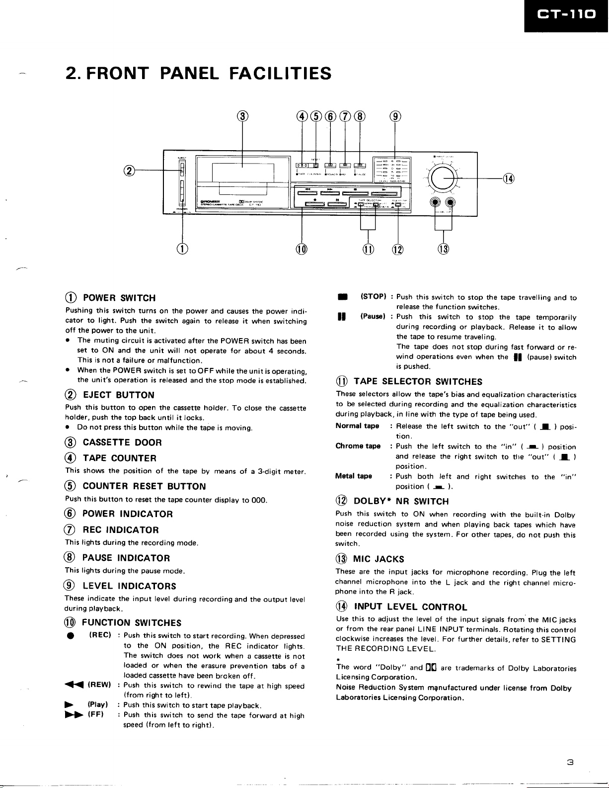
2.
FRONT
PANEL
FACILITIES
eowen
@
Pushing
cator
off the
.
.
@
Push
holder,
.
@
@
This
@
Push
@
@
This lights
@
This lights
@
These
during
@
<
>>
this
light.
to
power
The muting
set
to ON
This is
not
When
the
the unit's
e.lecr
this button
push
Do not
cnsserrE
reee
shows the
coururEn
this
button
eowen
nec
during the recording
enuse
during
LEVEL
indicate
playback.
rurucrroN
(REC)
O
(REWI
(FF)
swrrcH
switch turns
Push
to
the unit.
circuit is
and the unit
failure
a
POWER
operation
BUTToN
to open the cassette holder.
the top
press
this button
on the
the switch
activated after the POWER
will
or malfunction.
is
switch
is released
back until it locks.
while the tape is moving.
DooR
couNTER
position
to reset
tNDtcAToR
tNDtcAToR
rNDtcAToR
tNDtcAToRs
the input
of the tape by means
REsET BUTToN
the tape counter
pause
the
mode.
level
during
swtrcHEs
:
Push
this switch
to the
The
switch does not
loaded
loaded
:
Push
(from
:
Push
speed
position,
ON
or when the
cassette have
this switch
right
to
this
switch to send
(from
left
power
and causes the
again to release
not
operate
set to
mode.
to
teft).
to right).
OFF
and the
recording
start
work when
erasure
been
rewind
to
while
stop
display
recording.
the REC
broken off.
the tape
power
it when
for
the unit
mode
To
of a 3-digit
to 000.
and the output level
prevention
the tape at high
switching
has
switch
about 4
close the cassette
seconds.
is
operating,
is established.
When
depressed
indicator tights.
a cassette is not
tabs of
forward
indi-
been
meter.
speed
at hiqh
(STOPI
I
(Pausef
tl
reee sELEcroR
@
These
selectors
to
be selected during recording
playback,
during
Normal tape
Chrome tape :
Motal tapo :
oolav*
@
Push
this
noise reduction
been recorded
switch.
rurc
@
These
are the input
channel
phone
into
rrueur
@
Use this to
from
or
clockwise
THE
RECORDING
a
The
word
Lice nsi ng
Noise Reduction
Laboratories
:
Push
release
:
Push
during recording
the tape
The tape
wind operations
pushed.
as
allow the tape's
in line
:
Release
tton.
Push
and
oosition.
Push
position (
NR
switch to
system and
using
JAcKs
microphone
the R
.iack.
LEvEL
adlust the level
panel
the rear
increases
"Dolby"
Corporation.
System
Licensi
this
switch to stop the tape travelling
function
the
this
switch to
resume
to
does not stop
switches.
stop the tape temporarily
playback.
or
traveling.
during
even
when tne
swtrcHEs
bias and equalization
and the equalization
with the
the left
release
both
the
-
type of tape
teft
switch to the
switch to
the right
left
and right
).
being used.
the
switch
switches
swtrcH
ON when recording
when
the system. For
jacks
for
microphone
the
L
jack
into
coNTRoL
input
of the
LINE INPUT
the level.
LEVEL.
and
ng
For further
are trademarks
D0
mqnufactured under
Corporation.
with the
playing
back tapes
other tapes,
recording.
and the right
signals
terminals. Rotating
details,
of Dolby
Release it
fast
forward
(nause)
ll
characteristics
characteristics
"out"
(
"in"
-
(
"out"
to tlre
to the
built-in Dolby
which have
not
do
plug
channel micro-
from
the
this
refer to
Laboratories
license from
and to
to allow
or re-
switch
posi-
I
)
position
)
(
I
,'in"
push
this
the left
MIC
iacks
control
SETTING
Dolby
)
5
3.
CIRCUIT
PLAYBACK
3.1
The
by the
signal
from the
Q102/Q103
fier. In the NORM
zation
NF
emitter. In the
is turned
switched
(120ps)
compensation
circuit between the
METAL
on,
and
from
120ps
DESCRIPTIONS
CIRCUIT
playback
2-stage
position,
Q103
and CrOz
the equalization characteristics
to
70ps
head
direct-coupled
playback
the
is achieved
collector and
positions,
to compensate the
frequency response. The level of the
output
is
amplified
parised
2 of the
through
Dolby IC.
This Dolby circuit consists
the
and
MPX filter ON/OFF
switch is OFF, the 19kHz
Dolby
The
IC401, and is
switching IC
by a variable resistor, and
set
by the
the
flat amplifier
Q401
MPX filter
of IC401
Dolby
ON/OFF switch
switch.
circuit
output appears at
passed
LINE OUTPUT via a
to
(IC402).
before being
and applied
(HA11226),
is linked to the
When
filter is bypassed.
is amplified
ampli-
equali-
the
by
Q102
Q104
EQ AMP
further
pin
to
Dolby
the
pin
8 of
Operations
during Each Mode
The mechanical
following
chapter
1. When
When the
applied to
period
0V to 5V
IC's
IC
into stop status which
four seconds
circuit changes
(see page
the
7).
POWER
POWER
pin
(Vcc)
1
pin
when
1 voltage is being
(approximately
intemal reset circuit is
after the
During this time, no
pressing
any of the other operation
PM9OO2
rcroz
operations effected by the
are described in the next
Switch
switch
is
Switched ON
is
switched on,
of IC102. During
*5V
the initial
increased from
from
activated,
maintained
is
power
switch is switched ON.
change can
B
0.6V to 2.4V)
putting
for about
be effected
control
the
the
by
buttons.
is
3.2 RECORDING CIRCUIT
The input signal from the
amplified
passed
INPUT
adjusted.
flat amplifierQ40l. D313 and
to
before
protect
to
signal amplified
the
appearing
adjusted
tion
the
to the
by the microphone amplifier
the
MIC/LINE
selector switch
via
volume control where the input
This
adjusted
IC103 form
IC103
signal is
protector
a
from large input signals.
by the flat amplifier
MPX filter
at
pin
to
pin
2 of the
8. The level of
by variable resistor. Then after
in the REC AMP
type of tape being
(Q106)
used, the signal
recording head.
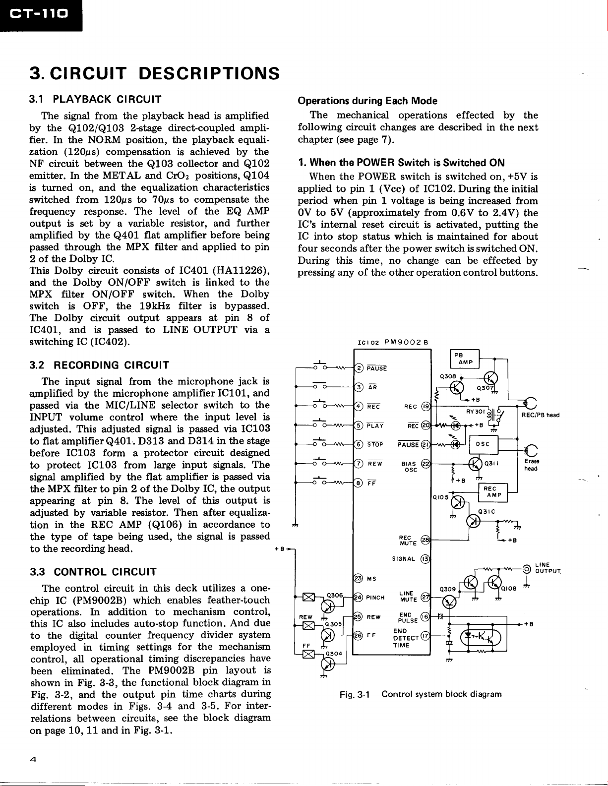
3.3 CONTROL CIRCUIT
The control circuit
chip IC
operations.
this IC
to
employed
control,
(PM90028)
In addition to
also includes
the digital
in timing settings
all operational
counter
been eliminated.
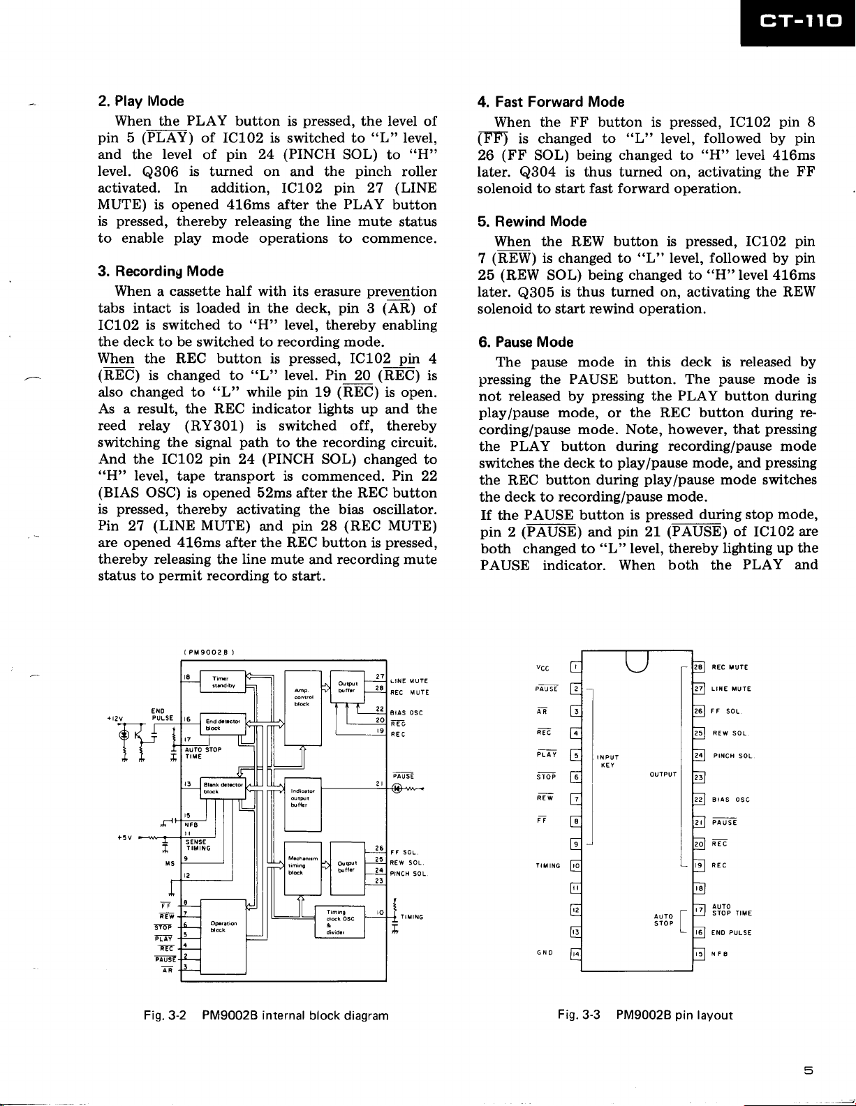
shown in
Fig. 3-2,
different
relations
page
on
Fig.
3-3,
and the output
modes
between circuits,
10, 11 and in
in
this
which
auto-stop
frequency
timing
PM9002B
The
functional
the
pin
in Figs. 3-4
see the
Fig.
3-1.
microphone
jack
IC101, and
to the
level is
passed
D314
via IC103
in
the stage
circuit designed
pa.ssed
is
Dolby IC,
the
output
this output
equaliza-
in accordance
passed
is
utilizes a one-
deck
enables
mechanism
feather-touch
control,
function. And
divider system
for the mechanism
discrepancies
pin
layout
block diagram
time charts
and 3-5.
during
For
block diagram
is
The
via
is
to
due
have
in
inter-
is
+g
pquse
an
REC
p
STOP
REW
MS
PINCH
REw
Er
Fig.3-1
REC
y
r-a
REc
PAUSE
BIAS
osc
oFa
MUTE
S IGNAL
LINE
MUTE
"iI&,
ENO
OETECT
TIME
Control system
block diagram
REC/PB
LINE
OUTPUI
head
4
Play
2.
pin
and
level.
activated. In addition,
MUTE)
is
to enable
3.
tabs intact is loaded in the deck,
ICLO?
the deck to be
When
(REC)
also
Mode
When
(FLAY)
5
the
Q306
the
level
PLAY
button is
of IC102 is switched to
pin
of
is
turned on and the
24
(PINCH
IC7O2
is opened 416ms
pressed,
thereby releasing the line mute
play
mode operations
after the
Recording Mode
When a cassette half with its
"L"
"H"
is
"L"
while
level,
recording
pressed,
level.
pin
is
switched to
switched to
REC button
the
is changed to
changed
to
pressed,
SOL) to
pin
PLAY
to
erasure
pin 3 (AR)
thereby enabling
mode.
Pin
(REC)
19
As a result, the REC indicator lights
reed relay
switching the
And
the IC102
"H"
level,
(BIAS
pressed,
is
Pin
27
opened 416ms
are
thereby releasing
status
to
(RY301)
signal
pin
is switched off, thereby
path
to the
(PINCH
24
tape transport is commenced.
OSC) is opened 52ms
thereby
(LINE
activating the
MUTE)
and
after
pin
after the REC button is
line mute
permit
the
recording
and recording mute
to
start.
recording
SOL) changed
the REC button
bias
(REC
28
the level of
"L"
level,
pinch
27
roller
(LINE
button
status
commence.
prevention
IC102
20
pin
(RE'C)
is open.
up and the
circuit.
Pin
oscillator.
MUTE)
pressed,
"H"
of
to
22
is
Fast Forward Mode
4.
When the
(-F-F)
is changed to
(FF
26
later.
Q304
solenoid
FF
SOL)
is
to start
button is
"L"
pressed,
level,
being changed to
thus turned
fast forward
on,
operation.
IC102
followed by
"H"
level 416ms
activating
pin
the
8
pin
FF
5. Rewind Mode
When the REW button is
(REW)
?
(REW
25
later.
is changed to
SOL)
Q305
is
being changed to
thus turned on, activating the
"L"
pressed,
level,
IC102
followed
"H"
level 416ms
by
REW
pin
pin
solenoid to start rewind operation.
Pause Mode
6.
4
pressing
not released by
play/pause
cording/pause
the
switches the
the
the deck to recording/pause
If the
pin 2 (PAUSE)
both changed to
PAUSE
pause
The
mode in this deck is released
PAUSE button. The
the
pressing
mode,
or
mode. Note, however,
PLAY button during
play/pause
button
pin
and
"L"
When both the
button during
REC
PAUSE
indicator.
deck to
pause
PLAY
the
button during
the REC button
that
recording/pause
mode, and
play/pause
mode switches
mode.
pressed
is
21
level, thereby
during stop
(PALJSE)
lighting
of
by
mode
is
during re-
pressing
mode
pressing
mode,
IC102
are
up the
PLAY and
+tzy PULSE
EX0
Fig.3-2
PM9002B
internal
block diagram
LINE MUlE
REC MUTE
osc
Bras
REC
vcc
plu
AR
REC
pTiv
s-ioF
n-EF
n
*
1,,,'
l
Fig.3-3
PM9002B
pin
REC IUTE
LITE MUTE
F F
SOL
REW
Pr{ca
AUTO
STOP TIME
ENO
NFg
layout
SOL
soL
PULS€
5
PAUSE
changed to
lights
this IC is
muted. If
pressed,
are changed to
REC
buttons
"L"
up. And
changed to
the REC and
IC102
PAUSE
and
are
level,
since
pin
"L"
signal circuit being
Furthermore,
of the signal
has been
mode is
o
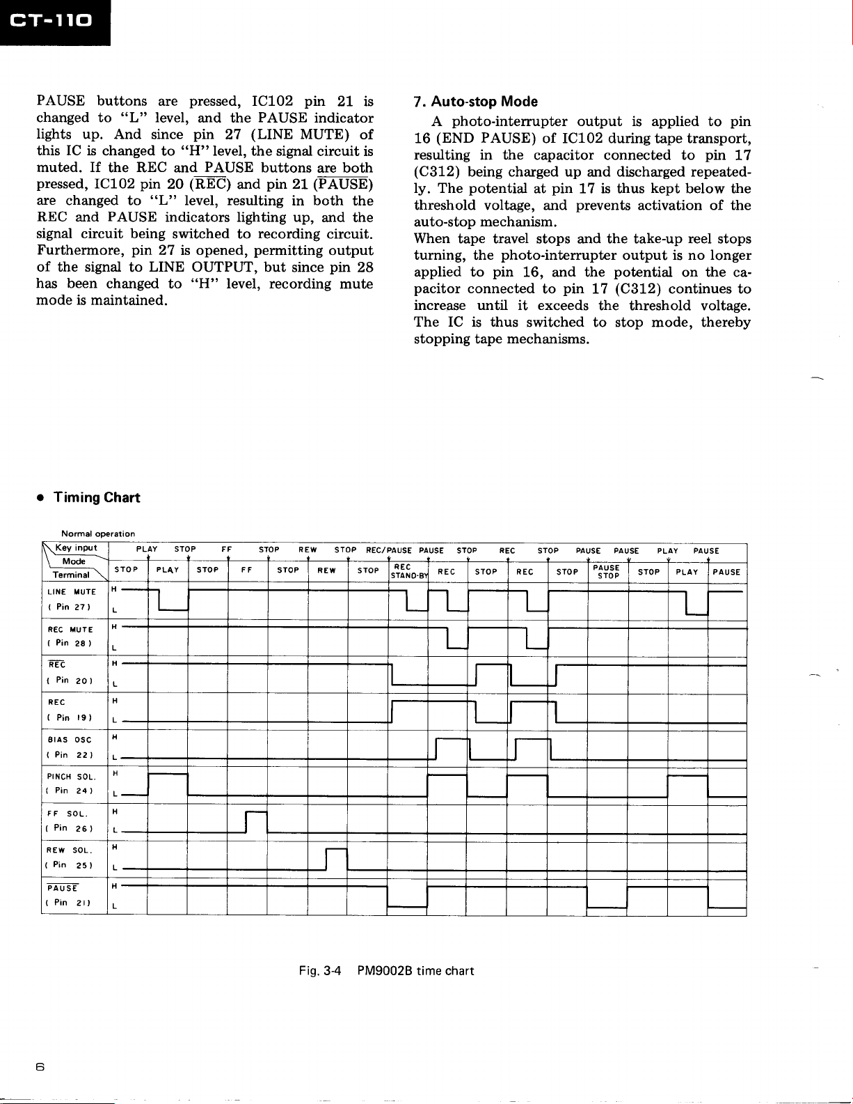
Timing
pin
27 is opened,
LINE OUTPUT,
to
changed
maintained.
Chart
pressed,
and the
pin
"H"
27
Ievel, the
PAUSE
20
tnEel
and
level, resulting
IC702
PAUSE
(LINE
buttons
pin
MUTE)
signal circuit is
pin
Zf
in both the
indicators lighting up,
switched to
recording
permitting
but
since
to
"H"
level, recording
2t is
indicator
of
are both
(FAUSB)
and the
circuit.
output
pin
28
mute
Auto-stop
7.
photo-interrupter
A
(END
16
resulting
(C312)
ly. The
threshold voltage, and
auto-stop
When
tape travel stops and the take-up reel stops
turning,
applied
pacitor
Mode
output is applied to
PAUSE)
of IC102 during tape transport,
in the capacitor connected to
being charged up
potential
at
pin
17 is thus
prevents
mechanism.
photo-interrupter
the
pin
to
connected
16, and the
pin
to
increase until it exceeds
The IC is thus
stopping tape
switched to stop mode, thereby
mechanisms.
pin
discharged repeated-
and
kept
below the
activation of the
output
potential
(CgLz\
L7
is no longer
on the ca-
continues to
the threshold voltage.
pin
17
Normal ooeration
Key input
\
.-
M.d"-
\
Terminal
IIUTE
LINE
(
Pin
27
1
R€C MUTE
(
Pin
28)
REC
(
Pin
20)
REC
(
19)
Pin
ErAS OSC
Pin
221
I
PINCH
SOL
(
Pin
24)
FF
SOL.
(
Pin
26)
REW
SOL.
(
Pin
25)
PAUSE
(
Pin
2t,
PLAY
STOP FF
lJr{
P PLAY
STO
\
H
I
L
STOP FF
STOP
STOP REW
REW
STOP
REC/PAUSE PAUSE
STOP
R€C
-L_
t_
STOP
STOP REC
REC
t_
STOP
STOP
PAUSE
PAUSE PLAY PAUSE
PAUSE
STOP
STOP
PLAY PAUSE
L
t_ t_
L
H
H
H
H
J
I I
J
J
J
_,r-
H
r
Fig.
3-4
PM9002B
time chart

Normal
op€rataon
Key
\
-M;A\
\
Terminal
LINE MUTE
Pin
I
REC MUTE
(
Pin
REC
(
Pin 20l
REC
(
Pin
AS
8r
(
Pin
PINCH SOL.
(
Pin 291
F F
SOL.
(
Pin 26)
REW SOL.
(
Pin
PAUSE
(
Pin 2l)
input
?rl
28)
19)
osc
221)
25
Oirsct
changs
FF
Blank
REC
PAUSE
STOP
\
H
L
REC
L
t_
H
fl
H
J
tl
L
H
H
1
MECHANICAL
3.4
Playback Mode
The
CT-110
when
shifting the
(Both
mounted on
o
the recording/playback
the
(see
Mode
Stop
The head base
mode is
presses
lever spring
gear
gear.
lever
(D)
keeping
belt-driven
shown in
down towards cam
(B).
(D),
clockwise torque is
Solenoid P is
(F)
is
kept
by the cam
gear
cam
by
counterclockwise
OPERATIONS
makes use
head
of the capstan
base during
playback
and erase heads
head
base).
Fig. 3-6)
mechanism
shift
With
Fig.
cam
Operating lever
3-6.
(C)
due to operating
(C)
combined with
applied
inactive,
against
gear
(D)
stopper
retum
stationary. The flywheel
and
spring
the hook
(G)
the capstan motor,
together with
the capstan
Fig.
during
to
this cam
of cam
(E),
thereby
and
3-5
torque
mode.
are
stop
(A)
cam
gear
of
gear
rotates
gear.
PM9002B
SotenojF
is
time chart
Gear lever return
(E)
spring
(Dl
gpar
Cam
Capstan
Nff."
Operating lever'Spring
Fig.3-6
STOP
operation
gear
(
Bl
Playback Mode
(see
Fis.
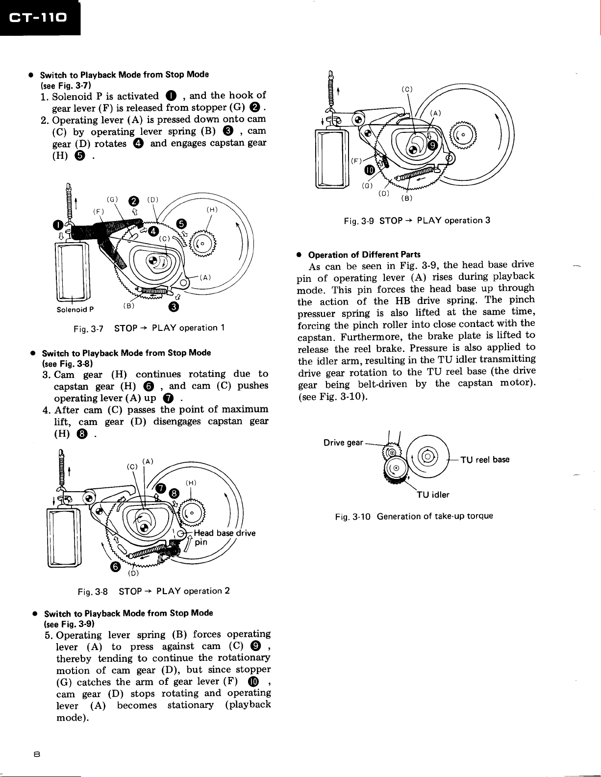
Solenoid
1.
gear
to
3-7)
lever
Switch
2. Operating
(C)
by operating
gear (D)
(H)0.
P
is activated
(F)
released
is
(A)
lever
rotates
@
from Stop
()
from stopper
pressed
is
spring
lever
engages
.nd
Mode
and
,
down
the
(B)
capstan
hook
(G)
onto
O ,
of
O
cam
ctun
gear
.
(B)
-+
Fig.
3-9
STOP
PLAY oPeration 3
Solenoid
Fig.3-7
(see
Cam
3.
to
Fig. 3€)
Switch
capstan
operating
4. After
lift, cam
(H)o.
P
STOP
Playback
geax
(H)
gear
(H)
lever
(C) passes
cam
gear
\e/
t!,
-+
PLAY operation
Mode from Stop
continues
attd
,
@
(A)
(D)
(c)
up
1A)
.
O
point
the
disengages
Mode
rotating
(C)
cam
of
capstan
1
due
pushes
maximum
gear
to
o
Operation
can
As
Different
of
be seen
pin of operating
pin forces
mode.
the
This
action
of
pressuer spring
pinch roller
iorcing
capstan.
releur"
the
drive
gear
(see
the
Furthermore,
reel
the
arm,
idler
gear
rotation
being
Fig. 3-10).
gear
Drive
Fig.3-10
resulting
belt-driven
Parts
Fig. 3-9,
in
(A) rises
lever
the
HB drive
the
lifted
also
is
into
the
brake.
Pressure
in
to the
by the
Generation
the
base
head
spring.
at
close
brake
is also
idler
TU
the
reel
TU
of take-up
base
head
during
up
The
same
the
contact
is lifted
plate
applied
transmitting
base
capstan
reel
TU
torque
drive
playback
through
pinch
time,
the
with
to
to
(the drive
motor)'
base
Switch
(see
Fig.
Operating
5.
lever
thereby
motion
(G)
cam
lever
mode).
(D)
Fig. 3-8 STOP
Playback
to
3'9)
(A)
catches
gezr (D)
(A)
Mode from Stop
lever spring
press
to
tending
cam
of
the arm
stops
becomes
-+
PLAY oPeration
(B)
against
continue
to
gear
(D), but since
gear
of
rotating
stationary
Mode
forces
cam
the
lever
and
2
operating
(C)
€)
rotationary
stopper
(F) (E
operating
(playback
,
,
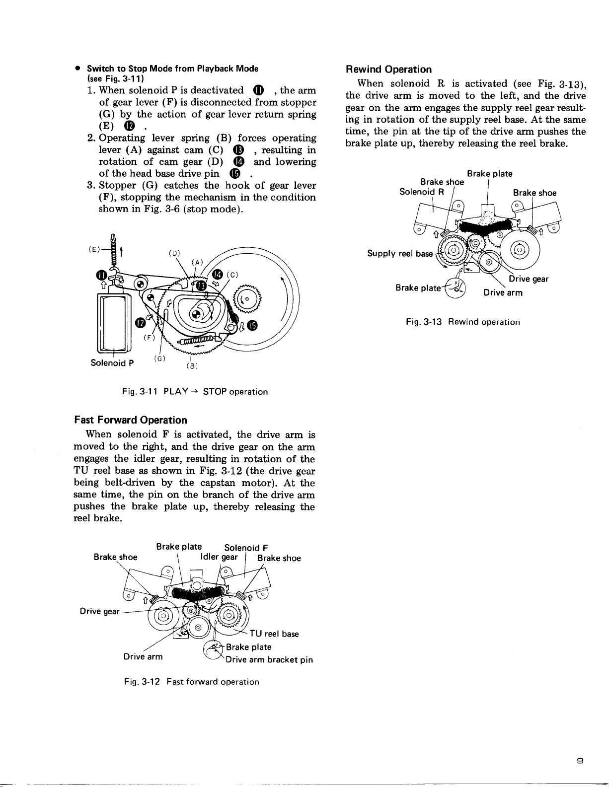
Switch to Stop
(see
Fig. 3-11)
When
1.
gear
of
(G)
bV the action of
(E)
Mode from Playback Mode
solenoid P is deactivated
(F)
lever
@
2. Operating lever
(A)
Iever
rotation
of the
3. Stopper
(F),
shown in Fig.
against cam
of cam
head
base drive
(G)
stopping
catches the hook of
the mechanism in the condition
3-6
O ,
is disconnected from
gear
lever
retum spring
(B)
(C)
forces
(D
,
and lowering
@
(p
resulting
spring
gear
pin
(D)
gear
(stop
mode).
the
arm
stopper
operating
in
lever
Rewind
When
Operation
solenoid R is activated
the drive arm is moved
gear
on
the arm
ing in rotation
the
plate
pin
time,
brake
engages
of the supply reel base. At
at the tip of
up,
thereby
Brake
Solenoid R
shoe
(see
Fig.
3-18),
to the left, and the drive
the supply reel
gear
result-
the same
the drive arm
releasing
plate
Brake
the reel brake.
pushes
I
the
Fig.
3-1 1
Fast Forward
When
moved
to the right,
engages
TU
reel base
Operation
solenoid F is
the idler
as shown
being belt-driven
same time,
pushes
the
the
brake
pin
reel brake.
-+
PLAY
STOP operation
activated, the drive
and the drive
gear,
resulting
Fig.
in
by
the capstan motor).
in rotation
3-12
on the branch
plate
up,
thereby releasing
gear
(the
of the
arm is
on the
of the
drive
At the
drive
arm
gear
arm
the
Supply
reel
base
Brake
Fig.
plate
3-13
Rewind
Drive arm
operation
Brake shoe
gear
Drive
Drive
Fig.
3-12
Brake
arm
Fast forward
plate
Solenoid F
TU reel
plate
Brake
Drive arm bracket
operation
base
pin
I
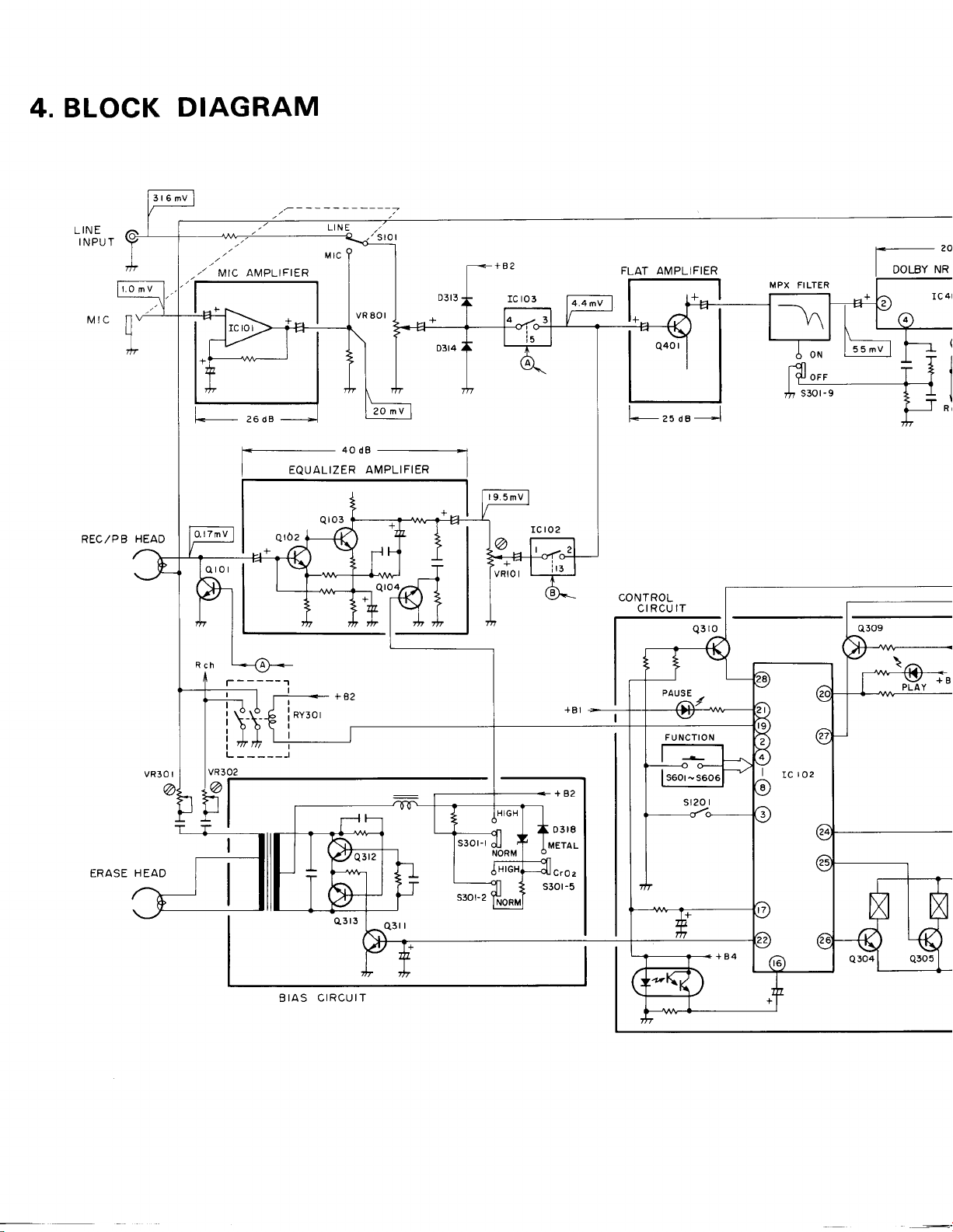
4. BLOCK
DIAGRAM
,.
MIC AMPLIFIER
+
t<_
25 dB
_____->l
REC,/PB
ERASE
HEAD
HEAD
EQUALIZER
AMPLIFIER
CONTROL
CIRCUIT
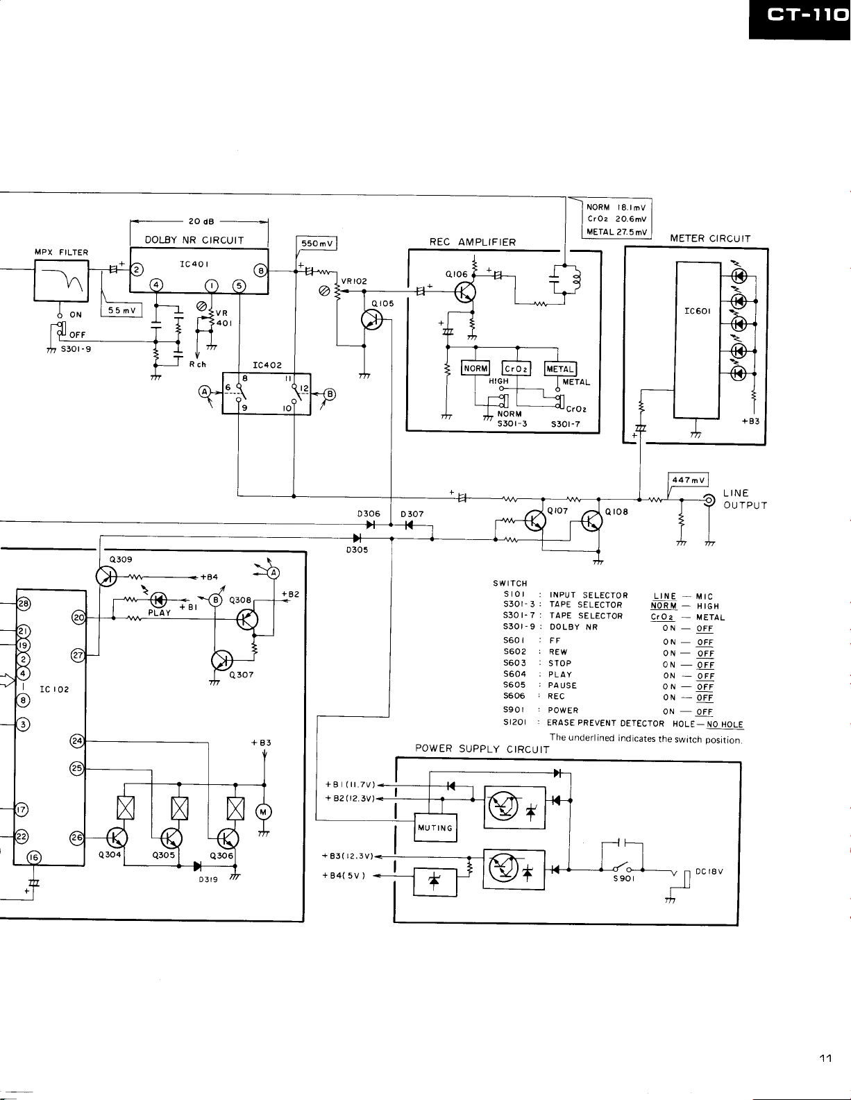
MPX
FILTER
I
DOLBY
--*l
20
dB
NR CtRcutT
METER
REC
I
AMPLIFIER
CIRCU IT
HIGH
I I
h6
-ql | -l
ffinu-c'o'
s30r-3
METAL
s30t-7
LINE
OU TPUT
swrTcH
stor
:
INPUT
SELECTOR
TAPE
s30r-7:
s30r-9;
s60r
s6O2
5604 i
I
roz
tc
POWER
SUPPLY
s605
s606
S9Ol
r20l
s
CIRCUIT
TAPE
DOLBY NR
:
FF
r
REW
STOP
PLA
.
PA
USE
r
REC
r
POW
ERASE
The
SELECTOR
SELECTOR
Y
ER
PREVENT
underlined
DETECTOR
indicates
LINE
I.IOR
CrOa
ON
ON
ON
oN
ON
oN
ON
the
-
-
U
-
-
-
-
-
-
-_qir
-
HOLE-
switch
MIC
II IEN
METAL
OFF
OFF
OFF
oFF
OFF
OFF
NO HOLE
position.
+Bt(il.7v)
+
82(12.3v)
+83(r2.3V)
+84(5V)
11
 Loading...