

Page 1

SPEAKER SYSTEM
cs-A700
Page 2
1.
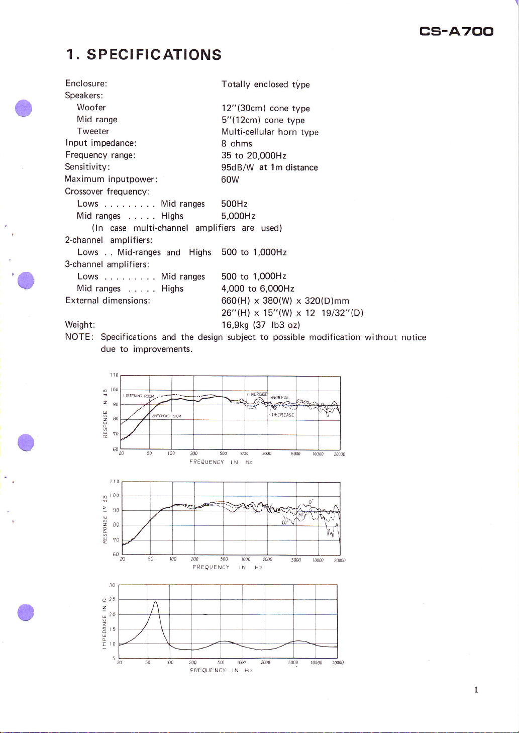
SPECIFICATIONS
cs-A700
'e
Enclosure:
Speakers:
Woof er
Mid range
Tweeter
lnput impedance:
Frequency
Sensitivity:
Maximum inputpower:
Crossover
Lows.
Midranges
range:
frequency:
Midranges
..
.....
(ln
case multi-channel amplifiers
Highs
2-channel amplifiers:
Lows
. . Mid-ranges and
3-channel
amplifiers:
Lows. .. Midranges
Midranges
External
Weight:
NOTE:
..... Highs
dimensions:
Specifications and the design subject
to improvements.
due
1t0
i00
o
L|STENIT
rw
--
-lt
7so
U
2ao
|#70
60
--z
/'K;
Highs
........
200
FREQU
Totally enclosed
12"(30cm) cone
5"(12cm) cone
Multi-cellular
8 ohms
35
to 20,000H2
95dB/W
at 1m
60w
500H2
5,000H2
are
used)
500 to 1,000H2
to 1.000H2
500
4,000 to 6,000H2
660(H) x 380(W) x
26"(H)
16.9ks
x 15"(W)
(37
to
rlNClll5
rNoihAL
/A
\=r
t;,,";;
500
Y
n00 2w
I N liz
FNC
t\rpe
type
type
horn
distance
lb3
oz)
possible
type
320(D)mm
x 12
19132"(Dl
modification without notice
^V.r;{
\'
t00
6
3so
260
H?o
30
a ?5
z
ro
a
r5
A
!'0
a0\
0'
\.,^"/
sma.
-4\4
60
5
200 500
500
240
FREQUENCY
FREQUENcY
1000
I N Hz
lm
i N Hz
2000
Page 3
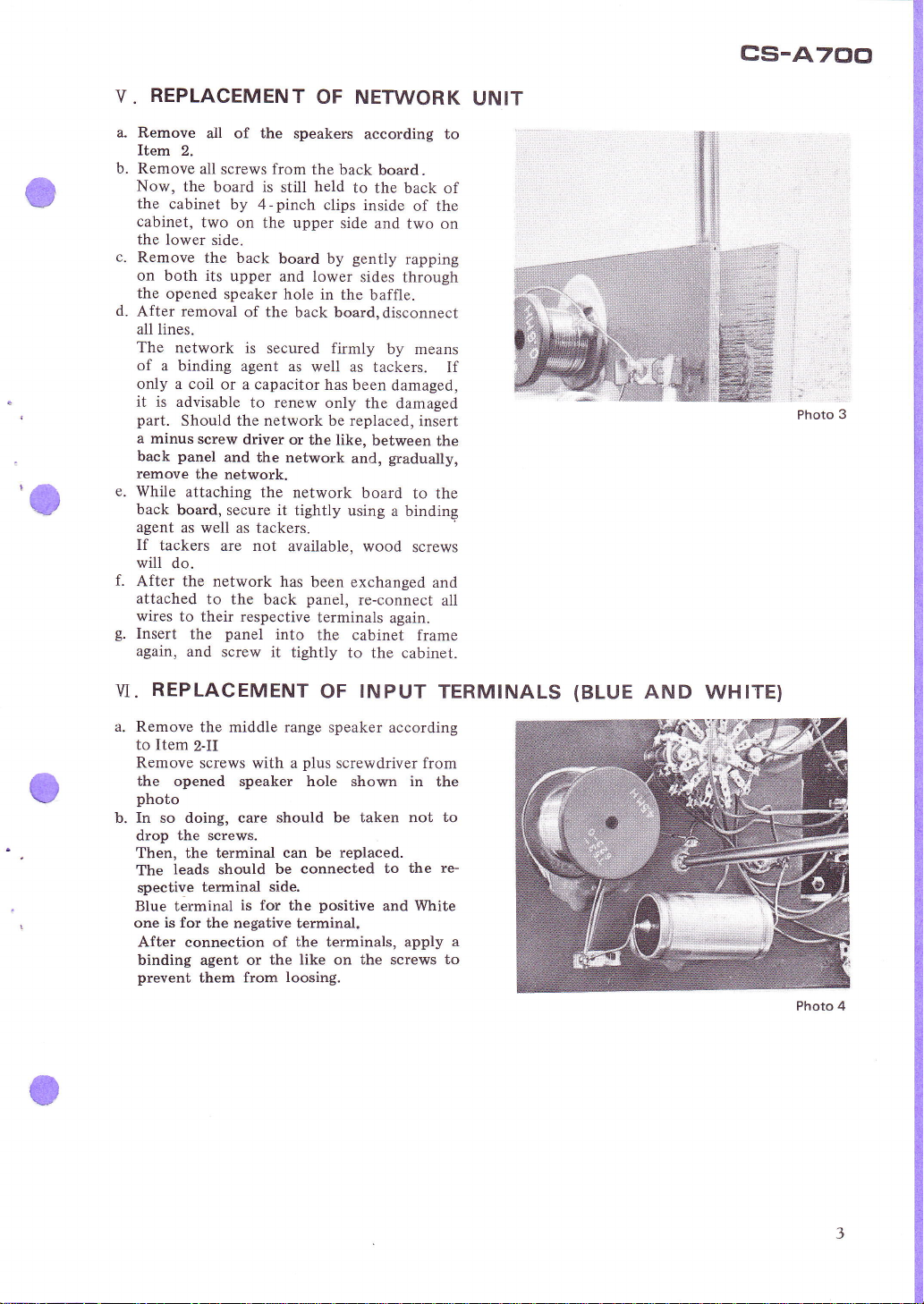
REPLACEMENT
V.
OF NETWORK
cs-A700
UNIT
'O
Remove
Item
b.
2.
Remove
Now,
the
the cabinet
cabinet,
the lower
c.
Remove
on both its
the
opened
d.
After removal
all lines.
The
network
of a binding
only a coil
it is
advisable
part.
Should the network be replaced,
a
minus
panel
back
remove
While
attaching
back
board,
agent as
If
tackers
wili
do.
After the
attached
wires
to their respective
Insert
again,
all of the
all
screws from
board is
by 4-pinch
two on
side.
the back
upper and
speaker hole
or a capacitor
screw
and
the
network.
secure it
well as
are not
network
to the
panel
the
and
screw it
speakers
still
the upper
board by
according to
the
back
held
to
clips inside
side and
gently
lower
sides
in the
baffle.
board.
the back
of the
two on
rapping
through
of the back board,disconnect
is secured
agent
to renew
driver or
the network
the
tackers.
back
into
firmly
as well as
the like,
network
tightly using
available, wood
has been
panel,
terminals
the
tightly
tackers.
has
been damaged,
only
the damaged
between
and,
board
exchanged
re-connect
cabinet frame
to the cabinet.
by means
insert
gradually,
to the
a binding
screws
and
again.
of
If
l',i
Photo 3
the
all
REPLACEMENT
VI.
a. Remove
to Item
Remove screws
the middie range
2-II
with a
plus
INPUT
OF
speaker according
screwdriver from
the opened speaker hole shown in
photo
b. In so doing, care
the screws.
drop
Then, the terminal
leads should
The
spective
Blue terminal
one
After
terminal
is for
the negative terminal,
connection
binding agent or
prevent
them from
should be taken not
can be
replaced.
be connected
side,
the
positive
is
for
of the terminals, apply
the like on the screws
loosing.
to
and
TERMINALS
the
to
re-
the
White
a
to
(BLUE
AND
WHITE)
Photo 4
Page 4

z.REPLACEMENT
12"WOOFER
r
.
OF S
PEAKER
UNI
T
leads
2)
Mount
board.
and
1),
off
a. Remove screws
pull
b. Pull the Blue and White
it out
from the speaker terminals.
holding the speaker,
gently
toward
you.
speaker
c. Mounting of NEW speaker.
lead end
the NEW speaker onto
Screw speaker
5''MID-RANGE
II.
the Red terminal.
onto
tightly onto the
the baffle
(Photo
(Photo
Push the Blue
baffle board.
a. Remove screws holding the speaker, and
pull
b. Pull the
it out
the
speaker terminals
c. Mounting
lead female end onto
of
the speaker
NEW speaker
the
board. Screw the
baffle board.
MULTI-CELLULAR
ru.
a. Remove screws
out
it
b.
the Red and
Pull
speaker
c. Mounting of NEW
lead
female end onto the Red side male
gently
Green
NEW speaker.
gently
terminals.
holding the speaker, and
toward
toward
and White leads off from
terminal.
onto the
speaker
you.
White leads off
speaker.
of the speaker, and
female
same speaker terminal.
Then, mount the NEW speaker onto the
baffle board.
Screw speaker tightly onto the baffle baord.
end onto the other male end of the
the
push
Red
you.
the Green
Push
side
Then,
male
mount
front baffle
tightly onto
HORN
from
Push the Red
the White
end
the
TYPE SPEAKER
puil
the
end
lead
Photo
1
C'
V.
The
CARE
TAKEN TO REPLACE
speakers of low
and middle ranges are
of the cone type; hence,
cap
should become damaged, the tone
quality
Therefore,
removal from cabinet and,
will be affected
carefulness should be used while
in the cabinet.
Viewing
are always
the
(Red
speaker
to
it from the
to
horn speaker.
is
side)
and the negative
the left side of the
back side,
identify the
The
to the right side
always
if
significantly.
bottom
positive
terminal is
speaker.
cone or
their
installed
again,
the terminals
terminal
A SPEAKER
side of
of the
always
Page 5

3. PARTS
FRONT VIEW
IDENTIFICATION
TWEETER
(YPT-4OsF)
REAR
VIEW
LEVEL
(Yw
LEVEL
(Yw
MID-RANGE
(Y
LATTICE
CONTROL
te-602-O)
CONTROL
te-603-O)
t 2-
to
tF)
BAFFLE
(Yw7s-604-o)
WOOFER
(Y3O-6
or
tF)
(Y3O-7O9F)
c'
INPUT
(YK
INPUT TERMINAL
TERMINAL
rs-6 r2-B)
(YKrs-6t2-C)
(BLUE)
(wHrTE)
Page 6

cs-A7C]0
ACTUAL APPEARANCE
M, GREENI
GREEN
OF NETWORK
T+
WHITE
RED
and
WHITE STRIPE
T"
RED
T3
WHITE
L,
SERVICE PARTS LIST
DESCRIPTION
Woofer
Mid-range
Tweeter
Lattice baffle
Network
case
(BLUE)
(WHITE)
(High
(Mid
Range)
.Range)
lnput terminal
lnput
terminal
Knob
Packing
Level control
Level control
PART NO.
Y3G61F or
Y
12-101F
YPT.405F
YWTs-604-0
YW17-618-O
YK15-612-B
YK15-612-C
YA19-621-0
YH35-608-O
YW18-602-0
YW18-603-0
WHITE
W
Y3O-709F
W*BLUE
Page 7

5.
OPERATIONAL
Your
speaker
following
1.
Connect
shown in Fig. 1.
2. Set
FULL
o-
When an
oscillator is transmitted into the FULL
RANGE
should
4.
When a 2kHzl2V-sine wave
oscillator
RANGE INPUT terminals, the mid-range
should
5.
When a
oscillator
RANGE INPUT
should
Be sure that each speaker
6.
range, and woofer) sounds well-balanced
in each range when
oscillator are
RANGE
from
system should be checked
procedures
test
the
the
INPUT
RANGE.
INPUT
sound well.
equipment
SELECTOR
8kHz/2V-sine wave
terminals, the tweeter
is transmitted into
sound well.
4ooHzl2Y-sine wave from the
is transmitted into the
terminals
sound well.
sine
transmitted into the
INPUT
to 20,000H2.
35
waves
terminals
CHECKS
by the
ai-ranged as
switch
from
the
from
the
FULL
the
FULL
the
woofer
(tweeter,
mid-
from the
FULL
in a range
OF
SPEAKER SYSTEM
7. In checking
to
HIGHS
the level
ually
8. In
checking
Items
keep sounding well-balanced
control
turned,
for highs is being
Items 4
MID-RANGE keeps sounding
the level control
while
anced
RANGE is being
9.
SCt
2-CH
10. TYansmit
ment
11. Check
INPUT SELECTOR SWitCh tO
thE
MULTI.
an output
HIGH
into
ltems
3, 4
RANGE.
and
72. Transmit an output
LOW RANGE.
into
Set
3.CH
Item 5.
INPUT SELECTOR
the
MULTI.
13. Check
74.
15. Transmit a sine wave into
check
Item 3.
a sine wave
Item 4.
a sine
wave
Item 5.
16.
77.
to check
TYansmit
to check
Transmit
to
6,
3 and
and
gtadually
from the test
6,
7.
be sure that
while
grad-
be sure that
well-bal-
MID-
for the
turned.
equip-
from test equipment
switch
HIGH
RANGE
into MID-RANGE
into LOW RANGE
to
AUDIO
OSCILLATOR
o
oo
V.T.
V.M
cs-A700
MULTI
INPUT
,ie
CH.
2
C|..,]'.
2
CH.
MULTI
"r"",-L*'l.o
CFr.
INPUT
I
RANGE
s
FULL
3CH.
MULTI
Page 8

F
o
6AO
T
-o-
E
2
0-209-tli,ll
<t?+{.
o5\t-J-e
d\$(1'o
=J
>5
E
E
2
/./t I /
//.6 I /
,''i--=-",
;
z
w \_7
Jrr
ij'o
o
-2
t t-
I
e o
<:
ri
o
o
+
6
E
f
t
(,
s
o
I
o'
Page 9

PACKING
6.
PROCEDURE
SPEAKER
CORNER
SYSTEM ITSELF
PAD
OPERATING
INSTRUCTIONS
SREVICE PAD
PACKING
VINYL BAG
CASE
(YH3s-6oa-o)
l"
UNIT
CARTON
t
7
Page 10

i
ir
i
i
i-
ll
ti
ll
I
I
I
PIclN
"15-5,
1'IclNEEFI
14O Smiih sr.,
EEFI
4-Chome,
ELECTFIGINICEI
ELECTFTGIN
Ohmoni- nishi,
Fanmingdate,Lt.,N.Y.
FIclNEEFI ELECTFICINIci
Fna.k.ijkler 64-68,
20OO A.twentr, Elelgrum
COPYRIGHT
IC
CclFIFGIFIATION
Ohca-ku, Tokyo,
U.S.A.
clctFIPOFIATIcrN
(EIJFIclPE
O)
11735.
NV
)
1970,9 PRINTED IN JAPAN
Japan
u.s.,A.
 Loading...