

Page 1
<R42-O94.-O>
Snruice%onr*/
SPEAKER
cs-A500
cs-A700
SYSTEM
<70J01Y22K> rJloNEEliL'
Page 2
1.
SPEC IFICATIONS
cs-A=ioo
,a
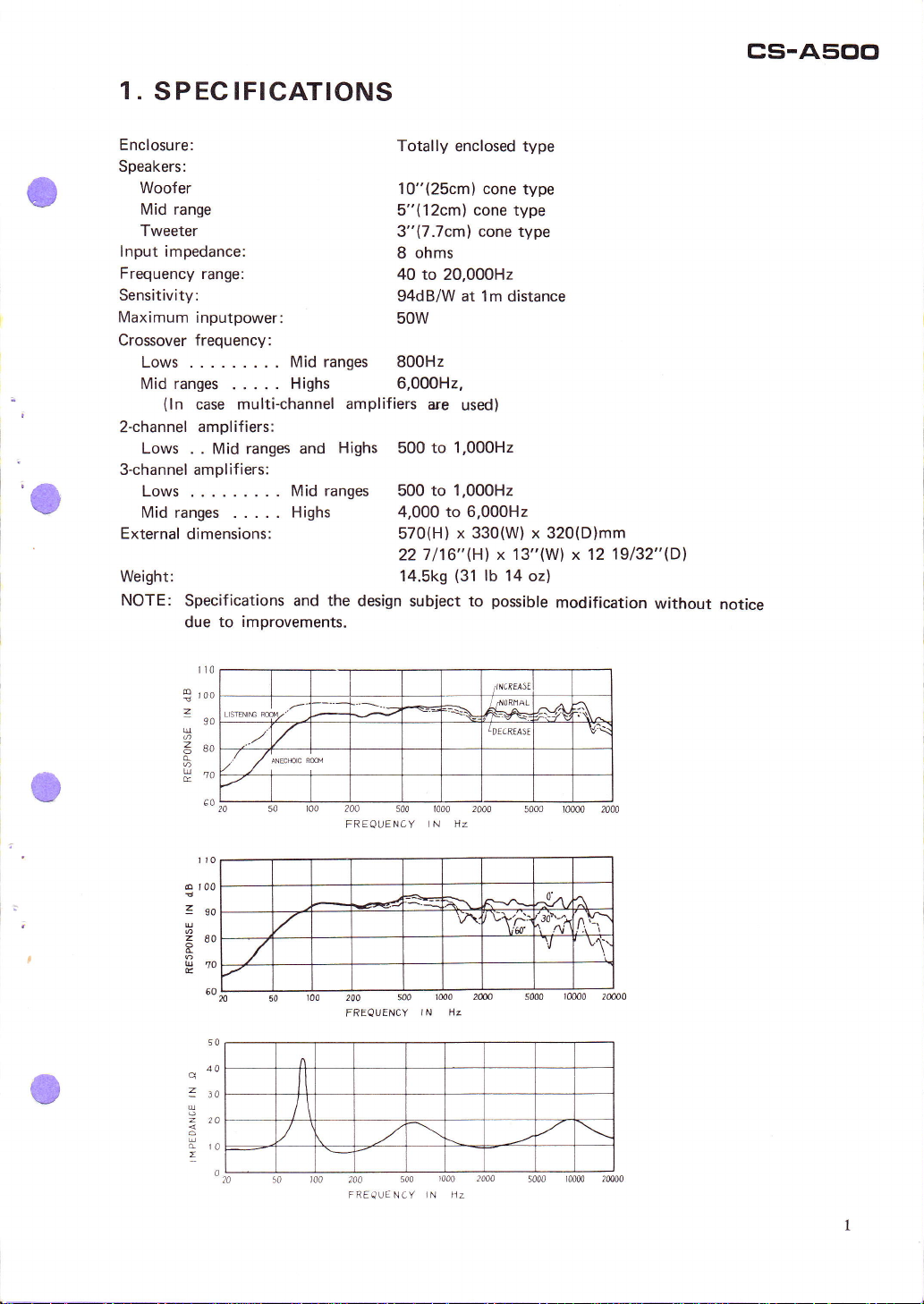
Enclosure:
Speakers:
Woofer
Mid range
Tweeter
lnput impedance:
Frequency range:
Sensitivity:
Maximum
Crossover frequency:
inputpower:
Lows. ..
Midranges
(ln
2-channel
Lows . .
3-channel amplifiers:
Lows . . .
Mid ranges
External
.....
case multi-channel
amplif iers:
ranges and
Mid
.....
dimensions:
Weight:
NOTE:
Specifications and the
due to
improvements.
Totally
enclosed type
10"(25cm) cone
5"(12cm) cone type
3"(7.7cml cone type
8 ohms
40
to 20,000H2
94dB/W at 1m distance
50w
Midranges
Highs
Highs 500
ranges 500 to 1,000H2
Mid
800H2
6,000H2,
amplifiers
are
used)
to 1,000H2
Highs 4,000to6,000H2
570(H)
22 7116"Hl
14.5k9
design subject
x 330(W) x 320(D)mm
x 13"(W) x 12
(31
lb
14 oz)
possible
to
type
modification
19132"(Dl
without
notice
roo
S
z
-
u
3eo
&
H"o
o
t00
zgo
4
280
d
u70
E
q
1to
u
d
z
90
6A
60
40
lo
LISTENIre W/'
./
r/
I
^rso'
w
204
500
FREQUENCY
500 1M0
200
FREQUENCY
5m
2A0
FREQUENCY
t000 2000
I N HZ
lN Hz
1000 2004
iN Az
/lNcRE/4Sl
d0RflAL
TDECREASE
v'{
\:,r'{:% f,vi
2M
^A
^t
lt \
V
Vq
v'\'
Page 3
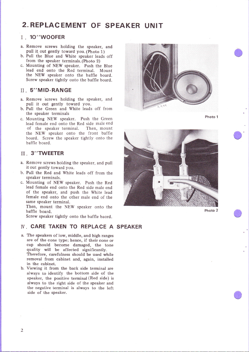
2.REPLACEMENT
lO"WOOFER
I
.
OF SPEAKER
UNIT
a. Remove
pull
b.
Pull
from
c.
Mounting
lead
the
Screw speaker
5''MID-RANGE
II.
a. Remove
pull
b. Pull the
screws
gently
i(
out
the Blue
the speaker
of NEW
end
onto
NEW
speaker
screws
out
Green
gently
it
holding
toward
and White
terminals.
speaker. Push
the Red terminal.
onto the baffle
tightly onto
holding the speaker,
toward
and White leads off
the speaker terminals
c. Mounting NEW
lead female
of
the speaker terminal. T'hen,
speaker.
end onto
the
the NEW speaker onto the
board.
baffle board.
3''TWEETER
il
.
a. Remove
gently
it out
b.
Pull the
speaker
c.
Mounting
lead
female
of
the
female
same
speaker
Then,
baffle
board.
Screw speaker
Screw the
screws
Red and White leads
terminals.
of
end
speaker,
end
onto
mount
speaker tightly onto
holding
toward
NEW
the speaker,
you.
speaker. Push
onto the
push
and
the other male
terminal.
the NEW
tightly
onto the
the speaker,
you.
(Photo
speaker leads
(Photo
2)
the
Mount
the baffle
you.
Push the Green
Red side
board.
board.
male
mount
front baffle
and
off from
Red side male
speaker
the Red
the White lead
end of the
onto the
baffle
baord.
1)
from
and
off
Blue
and
end
the
pull
the
end
Photo 1
Photo
o
2
CARE TAKEN TO REPLACE
N.
The
are
of the
cap
quality
Therefore,
removal
in
the cabinet.
Viewing
b.
always
speaker,
always
the negative
side
speakers
should
io
to the
of the
low,
of
cone type;
middle,
become
will be
from
it from
identify
the
affected significantly.
carefulness
cabinet
the back side
the bottom
positive
right side
terminal is always
speaker.
and high ranges
hence, if
damaged,
should
and, again, installed
terminal
of the speaker
their cone
the tone
used
be
terminal
of the
side
(Red
side) is
to the
while
are
and
left
A
SPEAKER
or
Page 4

€
REPLACEMENT
V.
a.
Remove all of the
Item 2.
b. Remove
Now,
the
cabinet,
the lower
c.
Remove
on both its
the opened
all
screws from
the board is
cabinet
by 4-pinch
two on the
side,
the back
upper and lower
speaker
d. After removal
all lines.
The network
of
a binding
only
a coil
it is
part.
a minus
back
remove
e.
While
back
agent
If
will
f.
After
attached
wires
g.
Insert
again,
tackers
or a capacitor
advisable
Should
screw driver or
panel
and the network and,
the
network.
attaching
board, secure it
as well as tackers.
are not
do.
the network
to the
to their respective
panel
the
and
screw it
OF NETWORK
speakers
the
held
still
clips inside
upper
board by
hole in
of the back
is
secured firmly
agent as
to renew
the network
well as
has been
only
the
the network
tightly using
available, wood
has been exchanged
panel,
back
terminals
into
the cabinet
tightly
according to
back board.
to
the back
of the
side and
gently
the
board,disconnect
sides
baffle.
two on
rapping
through
by means
tackers. If
damaged,
the damaged
be replaced, insert
like, between
board
re-connect
the
gradually,
to the
a binding
screws
and
all
again.
frame
to the cabinet.
of
UN IT
cs-A500
Photo
3
REPLACEMENT
U.
a.
Remove
to
Remove
the
photo
In
b.
drop
Then,
The
spective
Blue
one is for
side
After
binding
prevent
the
Item
2-II
screws with'a
opened speaker
so
doing,
the
screws.
the terminal
leads
should
terminal
tei-rninai
the
terminal.
connection
agent or
them from
middle
care
is for
negative.
the like
range
plus
hole
should
can
be
connected
side.
the
of the
loosing.
INPUT TERMINALS
OF
speaker
be
be
positive
terminals,
on
according
screwdriver
shown
taken
replaced.
to
and White
apply a
the screws
from
in the
not to
the
re_
to
(BLUE
AND
WHITE)
Photo
4
Page 5

PARTS
3.
IDENTIFICATION
FRONT
VIEW
TWEETER
(Y77-eoF)
LEVEL CONTROL
(Yw
ra-60
MID-RANGE
(Yt2-rorF)
LATTICE
(Yw7s-602-O)
WOOFER
(Y25-
t 4F-
t-o)
BAFFLE
t)
e
REAR VIEW
INPUT TERMINAL
(YK
r5-6 t2-B)
INPUT
(YK
TERMINAL
rs-6
t2-c)
(BLUE)
(wHrrE)
Page 6

cs-A500
ACTUAL APPEARANCE
WHITE A3
A,
A, GREEN
I I
OF NETWORK
RED
WHITE
A,
M*GREEN
M WHITE
RED
T*
WHITE
T
SERVICE PARTS
Woofer
Mid-range
Tweeier
Lattice
baffle
Network
lnput terminal
lnput
terminal
Knob
Packing
Level
control
(BLUEI
(WHITE)
case
LIST
Y25-14F-1
Y 12-101F
Y77-90F
YW75-602-0
YW17-617-O
YK
15-612-B
YK15612-C
YA19-621-0
YH35-607-O
YW18-601-0
W
W+BLUE
WHITE
Page 7

(,
s
o
E
o
f
t
o
+
6
F
=
2
t
zZz
rIt
E
:a
32:
d
o
=
fi!
96
=>
U
=;
u\
H'
=-
o
t
I
o
Page 8

5.
OPERATIONAL
Your
speaker
following procedures
1.
Connect
shown
2.
Set
FULL
3.
When
oscillator
RANGE
should sound
4.
When
oscillator is
RANGE
should sound
5.
When
oscillator is
RANGE
should
6.
Be
range,
in
oscillator
system
the
test
in
Fig.
the
INPUT
RANGE.
an SkHz/2V-sine
is
transmitted
INPUT
a 2kHzl2Y-sine
transmitted
INPUT
well.
Aoo}lzl2Y-sine
a
transmitted
INPUT
sound
sure that
each range
each speaker
and
woofer)
when sine
are transmitted
should
1.
well.
well.
RANGE INPUT
from
to 20,000H2.
40
CHECKS
be checked
equipment
SELECTOR
terminals,
terminals, the
terminals,
sounds well-balanced
terminals
arranged
switch
wave from
into
the FULL
the tweeter
from
wave
into
the
mid-range
wave from
into the
the
(tweeter,
waves
into
the FULL
in
by the
FULL
FULL
woofer
from
range
a
the
the
the
mid-
the
to
cs-AE
OF
SPEAKER
In
as
7.
8. In checking
9.
10. Tlansmit
11. Check
72. Transmit an
13. Check
t4.
15.
16.
t7.
checking
HIGHS keep sounding well-balanced
the level control
ually turned.
MID-RANGE
anced while
RANGE
the
set
2-CH
ment into
into
Set
3.CH
Tlansmit a
to check
TYansmit
the level control
is being
INPUT
MULTI.
an output
HIGH RANGE.
Items
LOW RANGE.
Item 5.
INPUT SELECTOR
the
MULTI.
sine
Item
a sine wave into
to check Item
check
a sine wave
Item 5.
Tlansmit
to
SYSTEM
Items
3 and
for highs is
Items
4
and
keeps sounding
gradually
SELECTOR
from the test
and
3, 4
output from test equipment
wave
3.
4.
7.
into
into
6,
6,
HIGH
be sure that
being
be sure that
for the
turned.
switch
switch to
MIDRANGE
LOW
oo
while
grad'
well-bal-
MID-
to
equip-
RANGE
RANGE
AUDIO
OSCILLATOR
o
oo
V.T.V.M
/VACUUM
\VOLT
METER
cs-A500
MULTI
2 cH.
TUBE\
INPUT
e@
CH.
3
FULL
/
CH.
3CH.
INPUT
I
RANGE
MULTI
Page 9

PACKING
6.
PROCEDURE
SPEAKER
SYSTEM
ITSELF
OPERATING
INSTRUCTIONS
SERVICE
PACKING
(YH35-607-O)
PAD
VINYL
CASE
BAG
l'
UNIT
CARTON
:
7
./
 Loading...