

PIONEER CD-IB100 Service Manual
ORDER NO.
CRT3656
CD-IB100 — /XJ/E5
RR
iPod
RR
ADAPTER
CD-IB100
—
/XJ/E5
For details, refer to "Important Check Points for Good Servicing".
PIONEER CORPORATION 4-1, Meguro 1-chome, Meguro-ku, Tokyo 153-8654, Japan
PIONEER ELECTRONICS (USA) INC. P.O. Box 1760, Long Beach, CA 90801-1760, U.S.A.
PIONEER EUROPE NV Haven 1087, Keetberglaan 1, 9120 Melsele, Belgium
PIONEER ELECTRONICS ASIACENTRE PTE. LTD. 253 Alexandra Road, #04-01, Singapore 159936
PIONEER CORPORATION 2006
K-ZZD. FEB. 2006 Printed in Japan

1234
SAFETY INFORMATION
CAUTION
A
This service manual is intended for qualified service technicians; it is not meant for the casual do-it-yourselfer.
Qualified technicians have the necessary test equipment and tools, and have been trained to properly and safely repair
complex products such as those covered by this manual.
Improperly performed repairs can adversely affect the safety and reliability of the product and may void the warranty.
If you are not qualified to perform the repair of this product properly and safely, you should not risk trying to do so
and refer the repair to a qualified service technician.
W
ARNING
This product contains lead in solder and certain electrical parts contain chemicals which are known to the state of
California to cause cancer, birth defects or other reproductive harm.
B
Health & Safety Code Section 25249.6 - Proposition 65
- Service Precaution
1.You should conform to the regulations governing the product (safety, radio and noise, and other regulations),
and should keep the safety during servicing by following the safety instructions described in this manual.
2. Be careful in handling ICs. Some ICs such as MOS type are so fragile that they can be damaged by
electrostatic induction.
C
D
E
F
2
1234
CD-IB100 — /XJ/E5
5678
[Important Check Points for Good Servicing]
In this manual, procedures that must be performed during repairs are marked with the below symbol.
Please be sure to confirm and follow these procedures.
1. Product safety
Please conform to product regulations (such as safety and radiation regulations), and maintain a safe servicing environment by
following the safety instructions described in this manual.
1 Use specified parts for repair.
Use genuine parts. Be sure to use important parts for safety.
2 Do not perform modifications without proper instructions.
Please follow the specified safety methods when modification(addition/change of parts) is required due to interferences such as
radio/TV interference and foreign noise.
3 Make sure the soldering of repaired locations is properly performed.
When you solder while repairing, please be sure that there are no cold solder and other debris.
Soldering should be finished with the proper quantity. (Refer to the example)
4 Make sure the screws are tightly fastened.
Please be sure that all screws are fastened, and that there are no loose screws.
5 Make sure each connectors are correctly inserted.
Please be sure that all connectors are inserted, and that there are no imperfect insertion.
6 Make sure the wiring cables are set to their original state.
Please replace the wiring and cables to the original state after repairs.
In addition, be sure that there are no pinched wires, etc.
7 Make sure screws and soldering scraps do not remain inside the product.
Please check that neither solder debris nor screws remain inside the product.
8 There should be no semi-broken wires, scratches, melting, etc. on the coating of the power cord.
Damaged power cords may lead to fire accidents, so please be sure that there are no damages.
If you find a damaged power cord, please exchange it with a suitable one.
9 There should be no spark traces or similar marks on the power plug.
When spark traces or similar marks are found on the power supply plug, please check the connection and advise on secure
connections and suitable usage. Please exchange the power cord if necessary.
0 Safe environment should be secured during servicing.
When you perform repairs, please pay attention to static electricity, furniture, household articles, etc. in order to prevent injuries.
Please pay attention to your surroundings and repair safely.
A
B
C
D
2. Adjustments
To keep the original performance of the products, optimum adjustments and confirmation of characteristics within specification.
Adjustments should be performed in accordance with the procedures/instructions described in this manual.
3. Lubricants, Glues, and Replacement parts
Use grease and adhesives that are equal to the specified substance.
Make sure the proper amount is applied.
4. Cleaning
For parts that require cleaning, such as optical pickups, tape deck heads, lenses and mirrors used in projection monitors, proper
cleaning should be performed to restore their performances.
5. Shipping mode and Shipping screws
To protect products from damages or failures during transit, the shipping mode should be set or the shipping screws should be
installed before shipment. Please be sure to follow this method especially if it is specified in this manual.
56
CD-IB100 — /XJ/E5
E
F
7
8
3

1234
CONTENTS
SAFETY INFORMATION..................................................................................................................................... 2
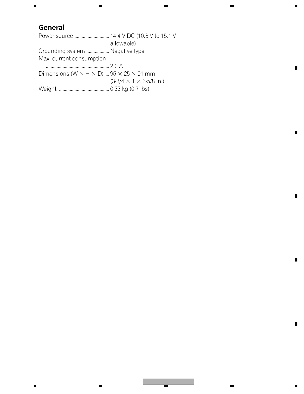
1. SPECIFICATIONS ............................................................................................................................................ 5
2. EXPLODED VIEWS AND PARTS LIST ............................................................................................................ 6
A
B
2.1 PACKING ................................................................................................................................................... 6
2.2 EXTERIOR................................................................................................................................................. 8
3. SCHEMATIC DIAGRAM ................................................................................................................................. 10
3.1 SCHEMATIC DIAGRAM(GUIDE PAGE) .................................................................................................. 10
4. PCB CONNECTION DIAGRAM ..................................................................................................................... 16
4.1 MAIN PWB UNIT...................................................................................................................................... 16
5. ELECTRICAL PARTS LIST ............................................................................................................................ 18
6. ADJUSTMENT ............................................................................................................................................... 20
6.1 TEST MODE ............................................................................................................................................ 20
7. GENERAL INFORMATION ............................................................................................................................. 22
7.1 DIAGNOSIS ............................................................................................................................................. 22
7.1.1 DISASSEMBLY ..................................................................................................................................... 22
7.1.2 CONNECTOR FUNCTION DESCRIPTION.......................................................................................... 23
7.2 IC ............................................................................................................................................................. 24
8. OPERATIONS ................................................................................................................................................ 26
C
D
E
F
4
1234
CD-IB100 — /XJ/E5
5678
1. SPECIFICATIONS
A
B
C
D
E
56
CD-IB100 — /XJ/E5
F
7
8
5
N
1234
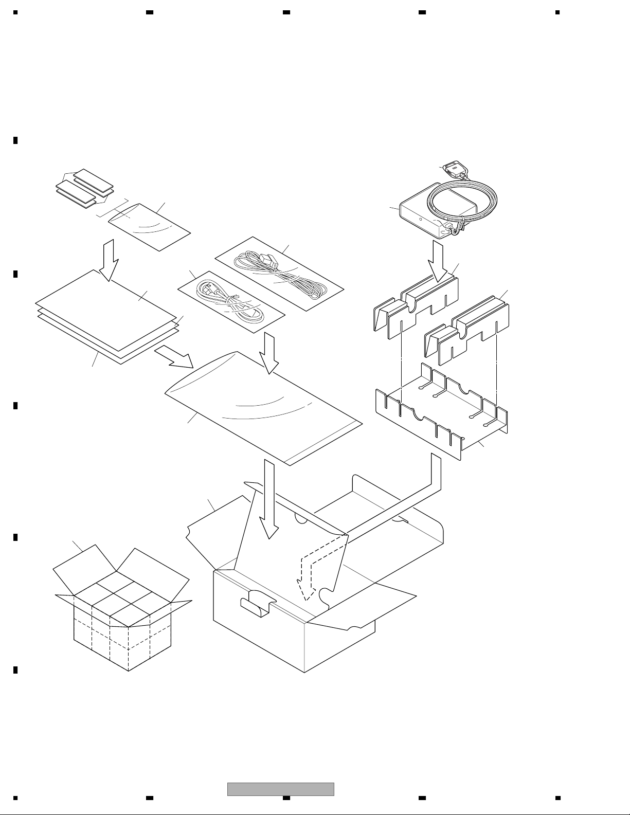
2. EXPLODED VIEWS AND PARTS LIST
OTES : • Parts marked by " * " are generally unavailable because they are not in our Master Spare Parts List.
• The > mark found on some component parts indicates the importance of the safety factor of the part.
A
Therefore, when replacing, be sure to use parts of identical designation.
• Screw adjacent to mark on the product are used for disassembly.
• For the applying amount of lubricants or glue, follow the instructions in this manual.
(In the case of no amount instructions,apply as you think it appropriate.)
2.1 PACKING
"
12
15
13
1
5
6
7
9
B
C
11
8
14
2
2
3
D
4
10
E
F
6
1234
CD-IB100 — /XJ/E5
5678
PACKING SECTION PARTS LIST
Mark No. Description Part No.
1 Protect Bag CZE2966
2 Spacer(S) CZH6631
3 Spacer(L) CZH6632
* 4 Carton CZH6650
5 DC Cord Assy(ES) CZD2993
6 BUS Cord Assy CZD2995
7 Owner's Manual CZR2997
8 Owner's Manual CZR2998
Owner's Manual
Mark No. Description Part No.
9 Polyethylene Bag CZE2962
* 10 Contain Box CZH6651
* 11 Velcro Fastener(Hard) CZE2964
* 12 Velcro Fastener(Soft) CZE2965
* 13 Polyethylene Bag CZE2967
* 14 Polyethylene Bag CZE2970
* 15 Caution Card CRP1332
A
Part No. Language
CZR2997 English, Spanish, German, French, Italian
CZR2998 Dutch, Portuguese(B), Traditional Chinese, Arabic
B
C
D
56
CD-IB100 — /XJ/E5
E
F
7
8
7
1234
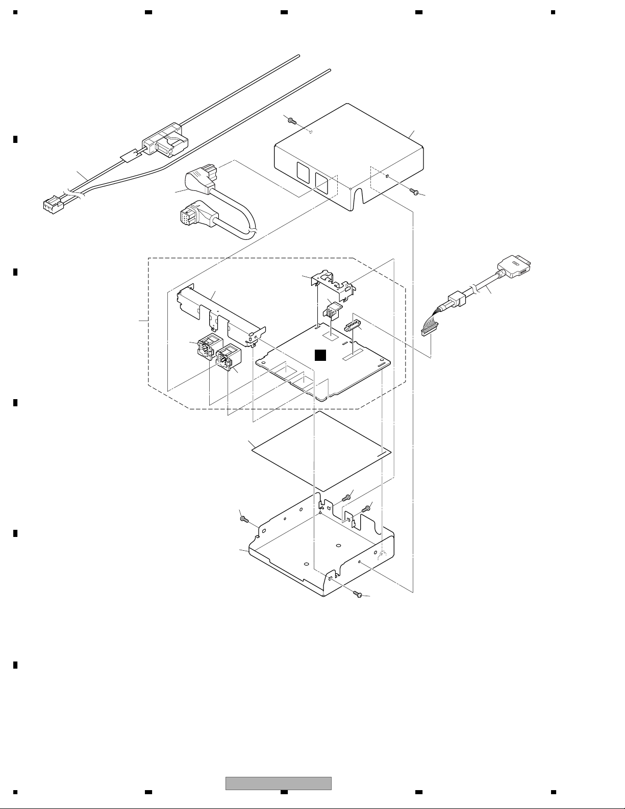
2.2 EXTERIOR
A
2
1
14
B
7
C
3
13
12
8
11
10
1
4
A
9
6
D
1
1
1
5
E
F
8
1234
CD-IB100 — /XJ/E5
1

5678
EXTERIOR SECTION PARTS LIST
Mark No. Description Part No.
1 Screw BSZ26P060FTB
2 DC Cord Assy(ES) CZD2993
3 BUS Cord Assy CZD2995
4 Cord Assy CZD5510
5 Chassis(Bottom) CZN6966
6 Insulator CZN6969
7 Main PWB Unit CZW5563
8 Plug(CN1) CZK2960
9 Connector(CN4) CKS3409
10 Connector(CN3) CKS3414
A
11 Connector(CN2) CKS4833
12 Holder(BUS) CZN6967
13 Holder(Power Supply) CZN6968
14 Chassis(Top) CZN8341
B
C
D
56
CD-IB100 — /XJ/E5
E
F
7
8
9
 Loading...