

Page 1
English
Español
Deutsch
Français
Italiano
Nederlands
AVG-VDP1
This product conforms to new cord colors.
Los colores de los cables de este producto se conforman con un nuevo código de colores.
Dieses Produkt entspricht den neuen Kabelfarben.
Le code de couleur des câbles utilisé pour ce produit est
nouveau.
Questo prodotto è conforme ai nuovi codici colori.
De kleuren van de snoeren van dit toestel zijn gewijzigd.
INSTALLATION MANUAL
MANUEL D’INSTALLATION
Page 2

1
Contents
Connecting the Units ................................ 2
IMPORTANT SAFEGUARDS ........................ 2
Connecting the system ...................................... 5
Connecting the power cord (1) .......................... 6
Connecting the power cord (2) .......................... 7
Installation .................................................. 9
To guard against electromagnetic
interference ................................................ 9
Installing this unit ............................................ 11
Installing the GPS antenna .............................. 12
Page 3

English
Español
Deutsch
Français
Italiano
Nederlands
Connecting the Units
2
IMPORTANT SAFEGUARDS
Before using your Vehicle Dynamics
Processor, be sure to read and fully understand the following safety information.
1 Read this manual fully and carefully
before operating your Vehicle
Dynamics Processor.
2 Keep this manual handy as a refer-
ence for future reference.
3 Pay close attention to all warnings
in this manual and follow the
instructions carefully.
4 Do not install the display where it
may (i) obstruct the driver’s vision,
(ii) impair the performance of any
of the vehicle’s operating systems or
safety features, including air bags,
hazard lamp buttons or (iii) impair
the driver’s ability to safely operate
the vehicle.
5 As with any accessory in your vehi-
cle’s interior, the display should not
divert your attention from the safe
operation of your vehicle. If you
experience difficulty in operating
the system or reading the display,
please park safely before making
adjustments.
6 Do not attempt to install or service
your Vehicle Dynamics Processor
by yourself. Installation or servicing
of the Vehicle Dynamics Processor
by persons without training and
experience in electronic equipment
and automotive accessories may be
dangerous and could expose you to
the risk of electric shock or other
hazards and can cause damage to
the system that is not covered by
warranty.
7 Please remember to wear your seat
belt at all times while operating
your vehicle. If you are ever in an
accident, your injuries can be considerably more severe if your seat
belt is not properly buckled.
8 To promote safety, certain functions
are disabled unless the parking
brake is applied.
Page 4

3
Connecting the Units
WARNING:
• To avoid the risk of accident and the
potential violation of applicable laws,
certain functions of this unit should
never be used while the vehicle is being
driven. Also, rear displays should not be
in a location where it is a visible distraction to the driver.
• In some countries or states the viewing
of images on a display inside a vehicle
even by persons other than the driver
may be illegal. Where such regulations
apply, they must be obeyed.
CAUTION:
• PIONEER does not recommend that
you install or service your Vehicle
Dynamics Processor yourself. Installing
or servicing the product may expose you
to risk of electric shock or other hazards. Refer all installation and servicing
of your Vehicle Dynamics Processor to
authorized Pioneer service personnel.
• Secure all wiring with cable clamps or
electrical tape. Do not allow any bare
wiring to remain exposed.
• Do not drill a hole into the engine compartment to connect the yellow lead of
the unit to the vehicle battery. Engine
vibration may eventually cause the insulation to fail at the point where the wire
passes from the passenger compartment
into the engine compartment. Take
extra care in securing the wire at this
point.
• It is extremely dangerous to allow the
GPS antenna cable to become wound
around the steering column or shift
lever. Be sure to install the unit in such
a way that it will not obstruct driving.
• Make sure that wires will not interfere
with moving parts of the vehicle, such as
the shift lever, parking brake or seat
sliding mechanism.
• Do not shorten any leads. If you do, the
protection circuit may fail to work
properly.
Page 5
English
Español
Deutsch
Français
Italiano
Nederlands
4
Note:
• This unit is for vehicles with a 12-volt battery and
negative grounding. Before installing it in a recreational vehicle, truck, or bus, check the battery
voltage.
• To avoid shorts in the electrical system, be sure to
disconnect the ≠ battery cable before beginning
installation.
• Refer to the owner’s manual for details on
connecting the power amp and other units, then
make connections correctly.
• Secure the wiring with cable clamps or adhesive
tape. To protect the wiring, wrap adhesive tape
around them where they lie against metal parts.
• Route and secure all wiring so it cannot touch any
moving parts, such as the gear shift, handbrake
and seat rails. Do not route wiring in places that
get hot, such as near the heater outlet. If the insulation of the wiring melts or gets torn, there is a
danger of the wiring short-circuiting to the vehicle
body.
• Don’t pass the yellow lead through a hole into the
engine compartment to connect to the battery.
This will damage the lead insulation and cause a
very dangerous short.
• Do not cut the GPS antenna cable to shorten it or
use an extension to make it longer. Altering the
antenna cable could result in a short circuit or
malfunction.
• Do not shorten any leads. If you do, the protection
circuit may fail to work when it should.
• Never feed power to other equipment by cutting
the insulation of the power supply lead of the unit
and tapping into the lead. The current capacity of
the lead will be exceeded, causing overheating.
• When replacing the fuse, be sure to only use a
fuse of the rating prescribed on the fuse holder.
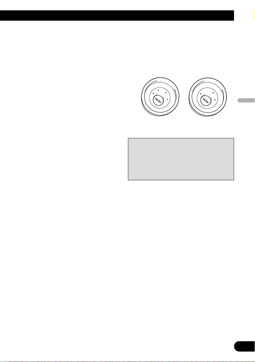
• If this unit is installed in a vehicle that does not
have an ACC (accessory) position on the ignition
switch, the red lead of the unit should be connected to a terminal coupled with ignition switch
ON/OFF operations. If this is not done, the vehicle battery may be drained when you are away
from the vehicle for several hours.
No ACC positionACC position
• Cords for this product and those for other products may be different colors even if they have
the same function. When connecting this product
to another product, refer to the supplied manuals
of both products and connect cords that have the
same function.
C
C
A
O
F
N
F
O
S
T
A
R
T
O
F
N
F
O
S
T
A
R
T
Page 6
5
Connecting the Units
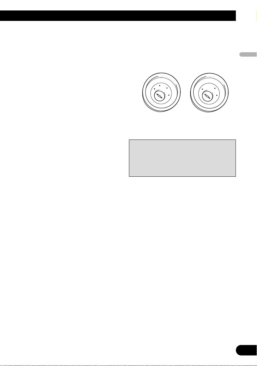
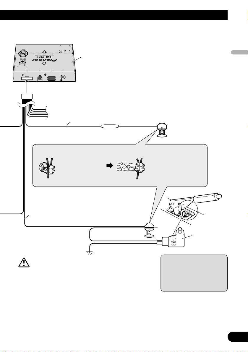
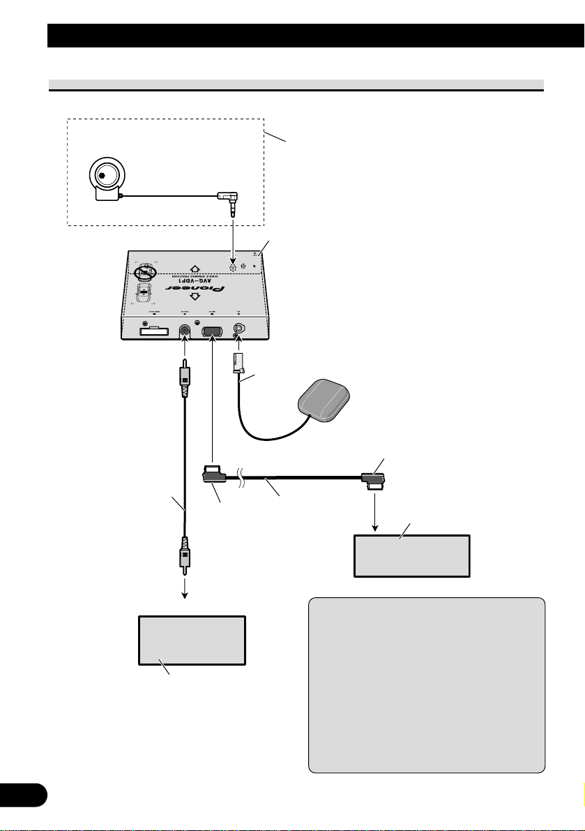
Connecting the system
This unit
Guide speaker
(e.g. CD-TS37GP)
(sold separately)
GPS antenna
Yellow
Black
26 pin cable
Display unit
(sold separately)
Video recorder with
RCA input jack
(sold separately)
To video input
RCA cable
(sold separately)
5 m
6 m
This unit’s guide speaker output terminal is used in
the following condition:
When the multi-channel processor and the display
unit that does not have a speaker output terminal is
connected to this unit.
Note:
• In the following cases, images may not be displayed properly on the display/VCR:
- When not displaying the V. D. P. image out-
put from this unit on the front display.
- When connecting the display/VCR which
has incompatible video output format with
this unit’s VIDEO OUT.
For more details, refer to the operation manual.
Page 7
6
English
Español
Deutsch
Français
Italiano
Nederlands
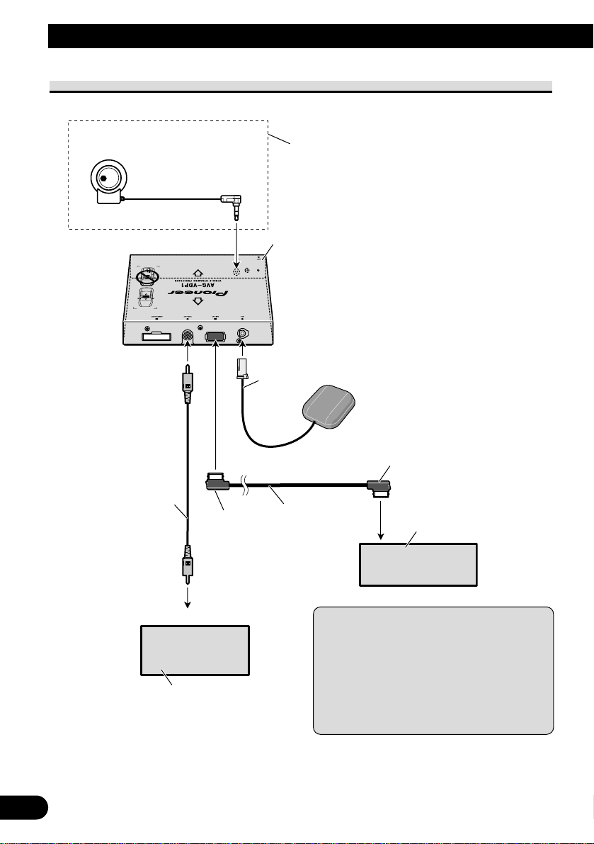
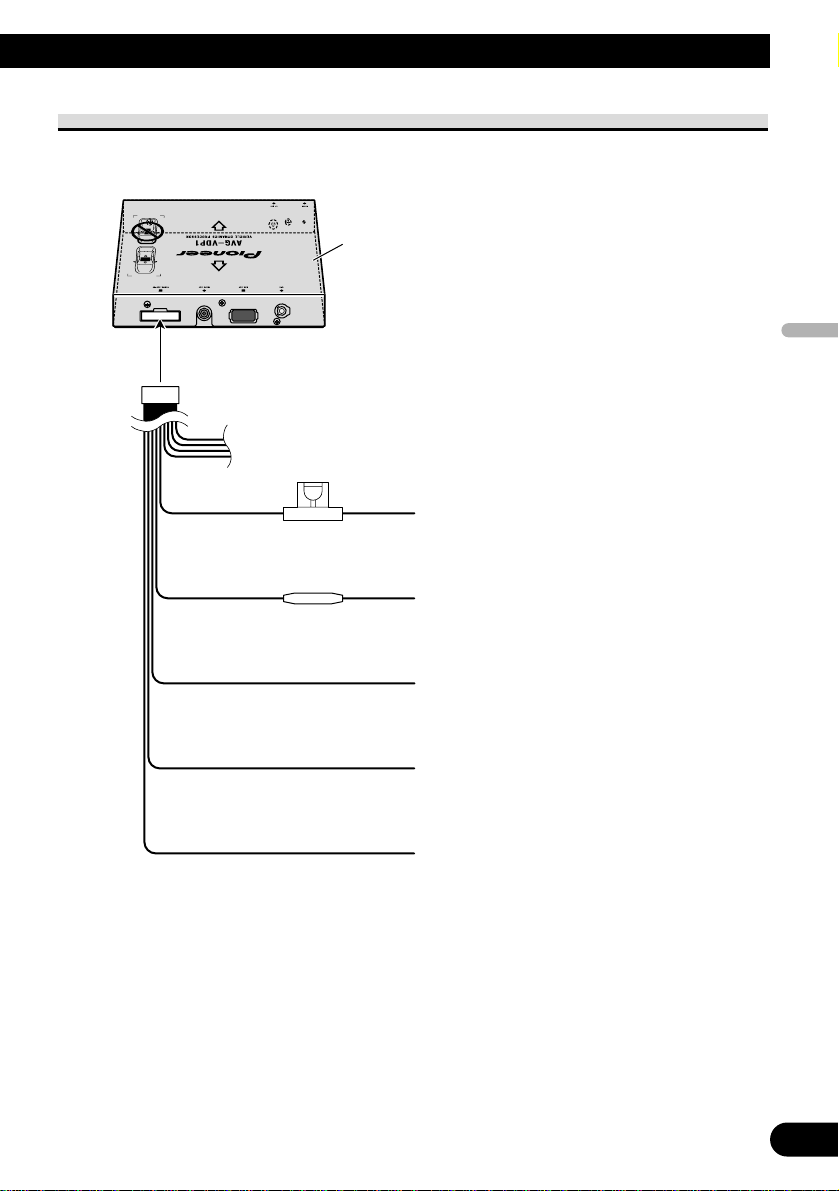
Connecting the power cord (1)
Fuse (4 A)
This unit
Fuse resistor
Yellow
To terminal always supplied with power
regardless of ignition switch position.
Red
To electric terminal controlled by ignition
switch (12 V DC) ON/OFF.
Black (ground)
To vehicle (metal) body.
White/black
To negative pole of the front left speaker
lead.
Gray/black
To negative pole of the front right speaker
lead.
Page 8
7
Connecting the Units
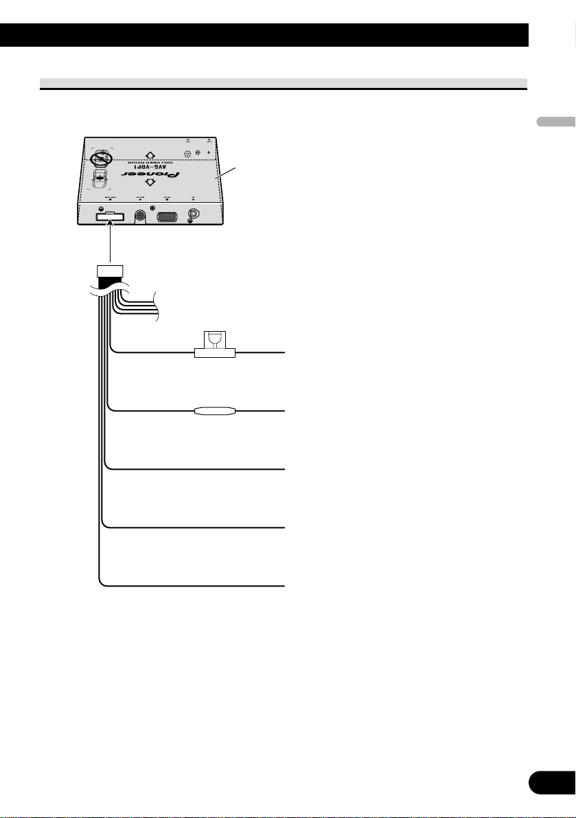
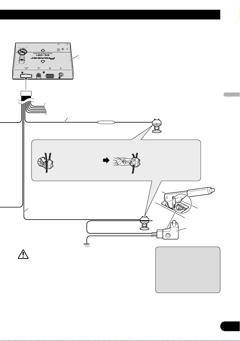
Connecting the power cord (2)
Pink
Used to detect the distance the vehicle travels.
Always connect the vehicle’s speed detection circuit. Failure to make this connection will increase
errors in GPS locator.
WARNING:
IMPROPER CONNECTION MAY RESULT IN
SERIOUS DAMAGE OR INJURY INCLUDING
ELECTRICAL SHOCK, AND INTERFERENCE
WITH THE OPERATION OF THE VEHICLE’S
ANTILOCK BRAKING SYSTEM, AUTOMATIC
TRANSMISSION AND SPEEDOMETER INDICATION.
Note:
• The position of the speed detection circuit
depends on the vehicle model. For details, consult your authorized Pioneer dealer or an installation professional.
Pink/black
Not used.
Page 9
English
Español
Deutsch
Français
Italiano
Nederlands
8
This unit
Violet/white
Of the two lead wires connected to the back lamp,
connect the one in which the voltage changes when
the gear shift is in REVERSE (R) position. If not
connected, this unit does not work properly.
Fuse resistor
Connection method
1. Clamp the lead. 2. Clamp firmly with
needle-nosed pliers.
Light green
Used to detect the ON/OFF status of the parking brake.
This lead must be connected to the power supply side of
the parking brake switch.
Parking brake
switch
Power supply side
Ground side
Note:
• The position of the parking
brake switch depends on the
vehicle model. For details,
consult the vehicle owner’s
manual or dealer.
WARNING:
LIGHT GREEN LEAD AT POWER CONNECTOR IS
DESIGNED TO DETECT PARKED STATUS AND
MUST BE CONNECTED TO THE POWER SUPPLY
SIDE OF THE PARKING BRAKE SWITCH.
IMPROPER CONNECTION OR USE OF THIS LEAD
MAY VIOLATE APPLICABLE LAW AND MAY
RESULT IN SERIOUS INJURY OR DAMAGE.
Page 10

9
Installation
Note:
• Before making a final installation of the unit,
temporarily connect the wiring to confirm that the
connections are correct and the system works
properly.
• Use only the parts included with the unit to
ensure proper installation. The use of unauthorized parts can cause malfunctions.
• Consult with your nearest dealer if installation
requires the drilling of holes or other modifications of the vehicle.
• Install the unit where it does not get in the driver’s way and cannot injure the passenger if there
is a sudden stop, like an emergency stop.
• When mounting this unit, make sure none of the
leads are trapped between this unit and the surrounding metalwork or fittings.
• Do not mount this unit near the heater outlet,
where it would be affected by heat, or near the
doors, where rainwater might splash onto it.
• Before drilling any mounting holes always check
behind where you want to drill the holes. Do not
drill into the gas line, brake line, electrical wiring
or other important parts.
• If this unit is installed in the passenger compartment, anchor it securely so it does not break free
while the car is moving, and cause injury or an
accident.
• If this unit is installed under a front seat, make
sure it does not obstruct seat movement. Route all
leads and cords carefully around the sliding
mechanism so they do not get caught or pinched
in the mechanism and cause a short circuit.
• Do not install this unit on the board covering the
spare tire or other places which are subject to
vibration.
• When installing this unit, choose a position that
ensures there will be no contact with luggage.
The impact of a heavy weight or sudden shock on
this unit will adversely affect the accurate display
of the current location of the vehicle.
• Avoid installing this unit in places where it will
interfere with loading and unloading of the spare
tire, jack, tools, etc.
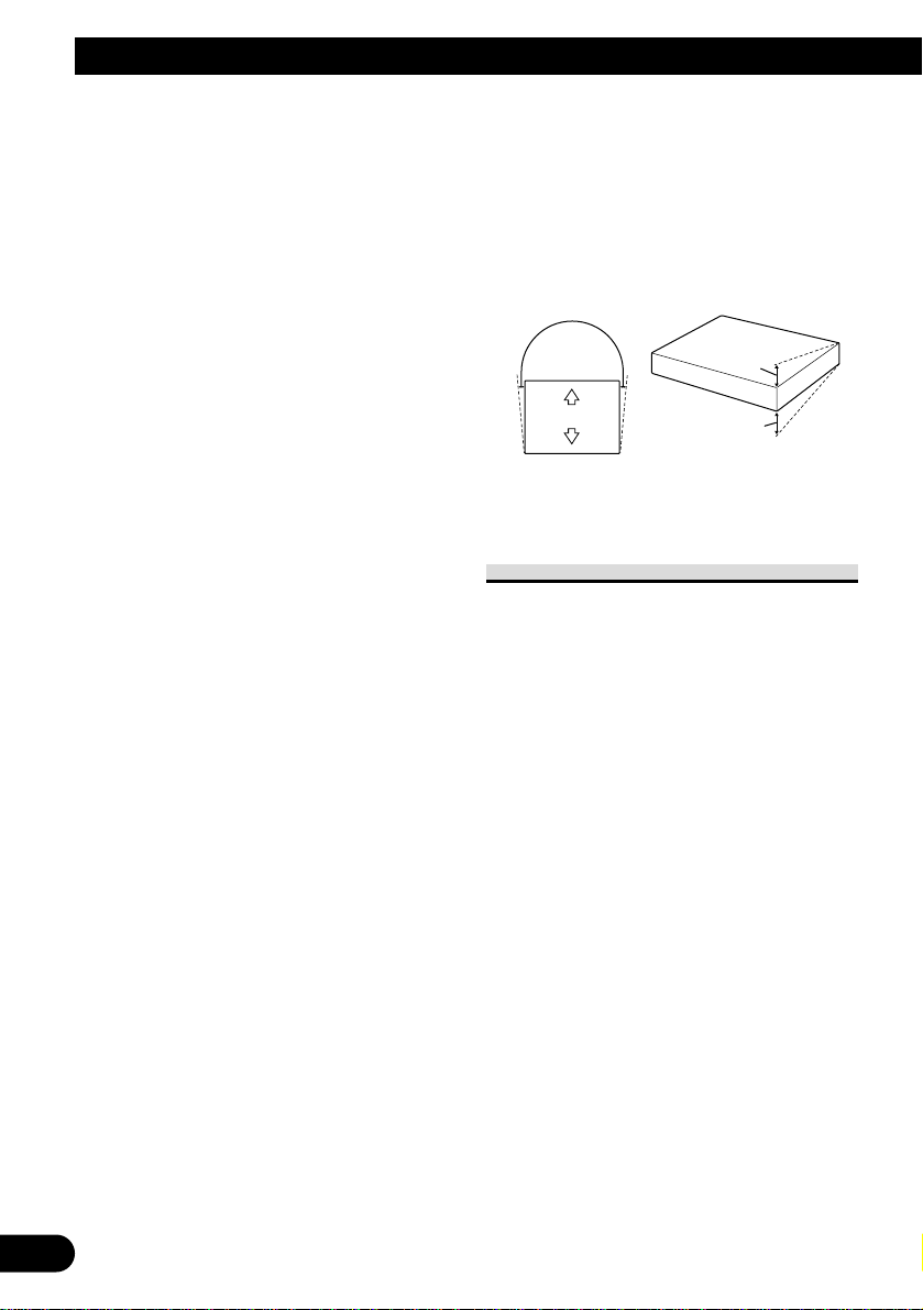
• Install this unit horizontally on a surface within
+30º to –30º tolerance (within 5º to the left or
right of your vehicle’s direction of travel). Misinstalling the unit with the surface tilted more
than these tolerances would increase the potential
for errors in the location display, and might otherwise cause reduced display performance.
To guard against electromagnetic
interference
In order to prevent interference, set the
following items as far as possible from
this unit, other cables or leads:
- TV antenna and its lead
- Radio antenna and its lead
- GPS antenna and its lead
In addition you should lay or route each
antenna lead as far as possible from other
antenna leads.
Do not bind them together, lay or route
them together, or cross them.
Such electromagnetic noise will increase
the potential for errors in the location display.
5°
30°
30°
Page 11
English
Español
Deutsch
Français
Italiano
Nederlands
10
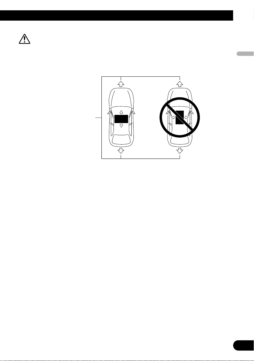
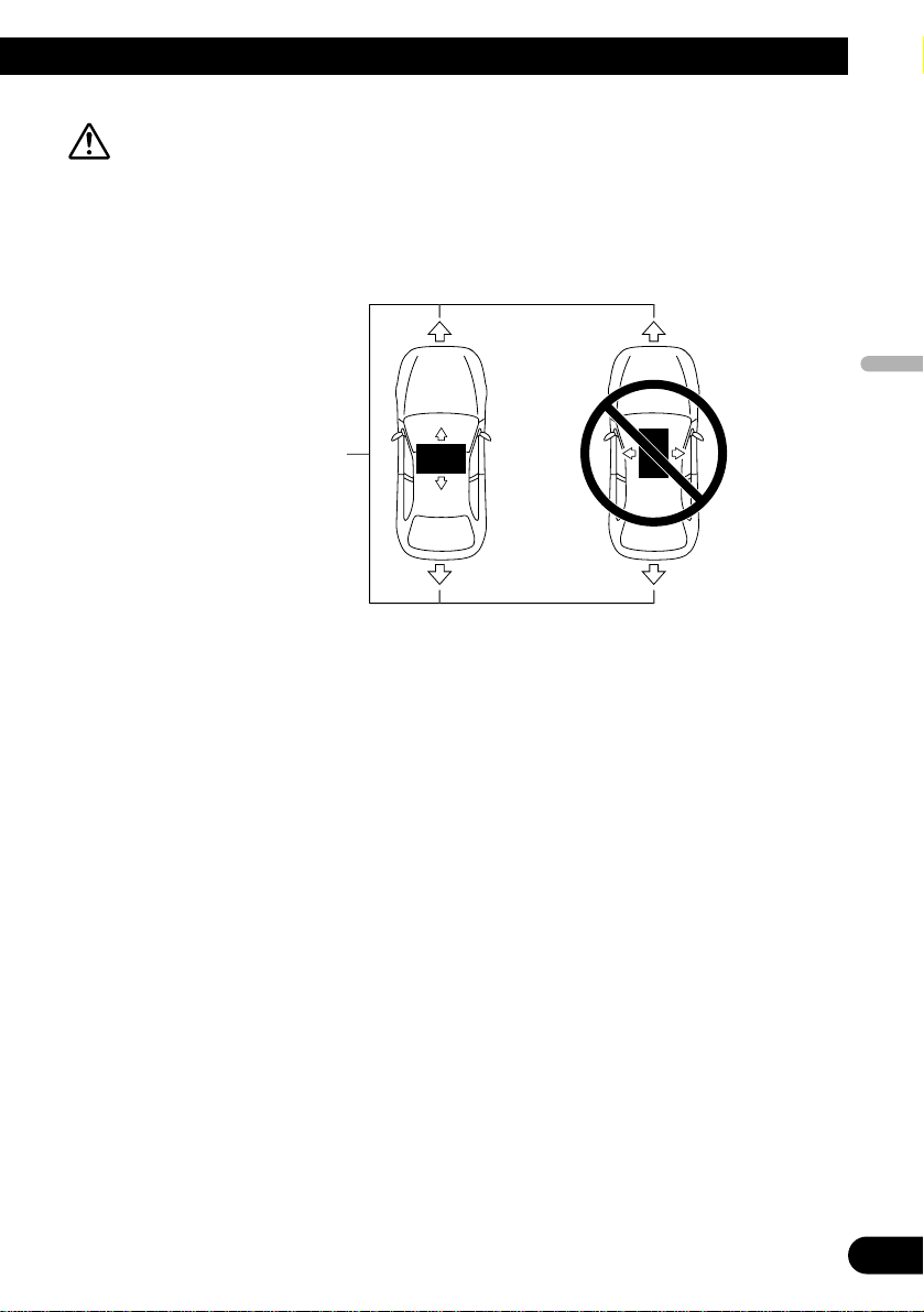
CAUTION:
• Install with the left and right sides of this unit perpendicular or parallel to
your vehicle’s direction of travel. Do not install diagonally to your vehicle’s
direction of travel or the current location will be displayed incorrectly.
• Be sure to install this unit on the floor with the silk printing side is facing up.
This unit will operate properly only in this position.
Forward/backward
direction of vehicle
Page 12
11
Installation
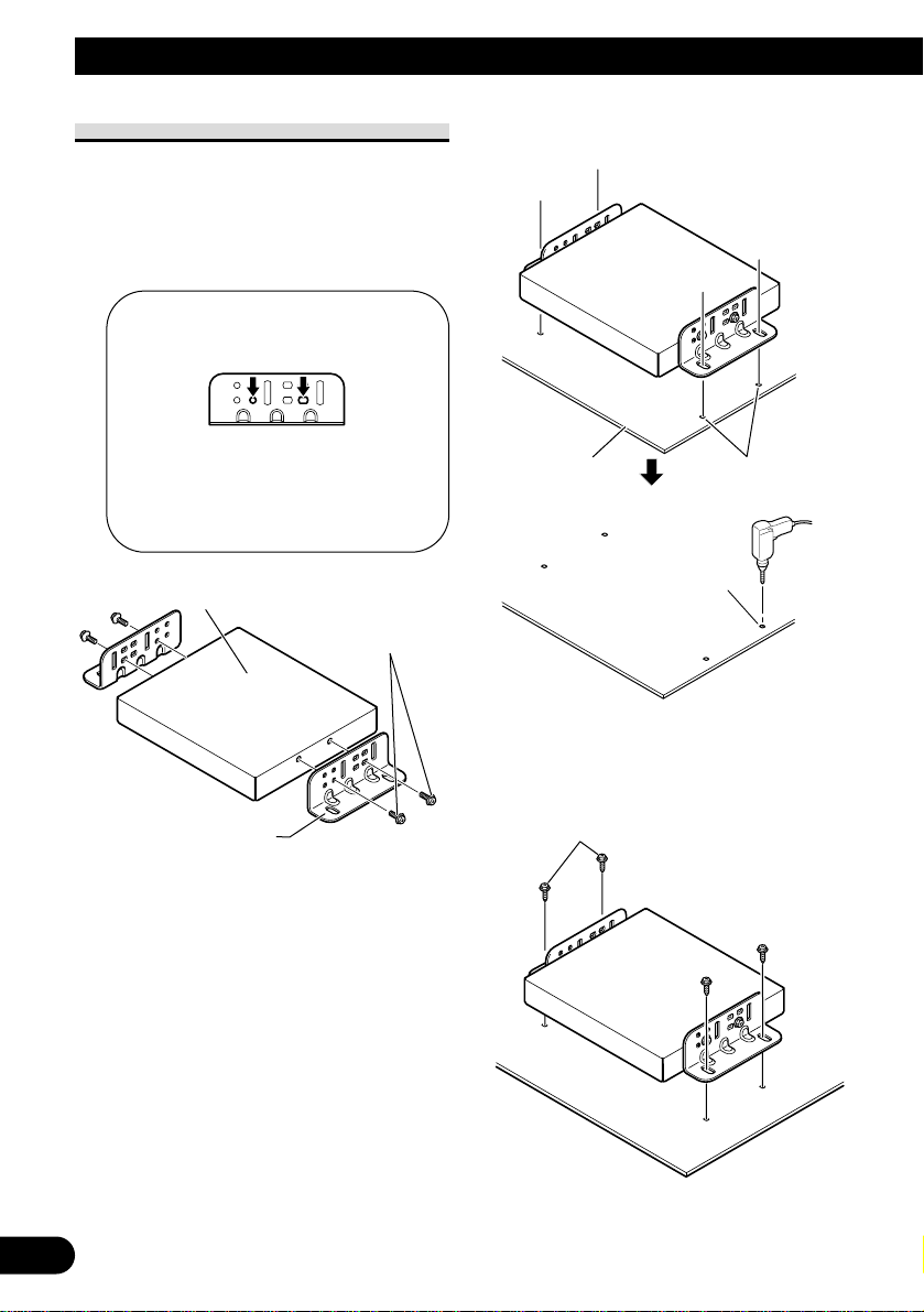
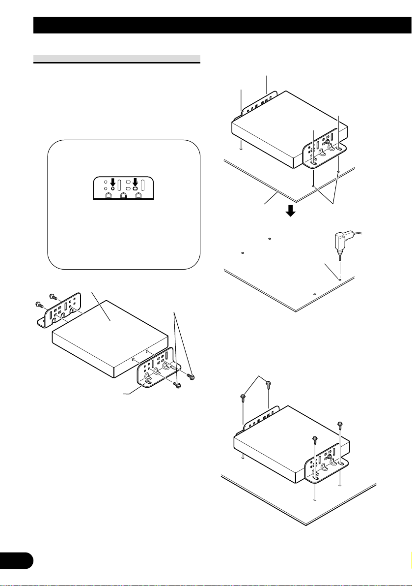
Installing this unit
1. Attach the side brackets to this unit.
When this unit is installed on the floor or
the installation board under the passenger
seat, etc., the side brackets should be
attached to the unit.
Use the following holes in the side
brackets.
If the positions of the side plates
are shifted in parallel you can also
use other holes that match up with
the holes in this unit.
When this unit is installed under the passenger seat, etc., use the installation board.
2. Decide on the installation position,
and drill the holes.
3. Secure it firmly using the self-tapping screws.
Drill holes of between
4 and 4.5 mm in
diameter.
Installation board
Mark up the positions for
drilling the holes.
Self-tapping screw
(6 × 16 mm)
This unit
Washer faced
screw (4 × 8 mm)
Side bracket
Page 13
12
English
Español
Deutsch
Français
Italiano
Nederlands
Installing the GPS antenna
CAUTION:
• Do not cut the GPS antenna lead
to shorten it or use an extension
to make it longer. Altering the
antenna cable could result in a
short circuit or malfunction and
permanent damage to the product.
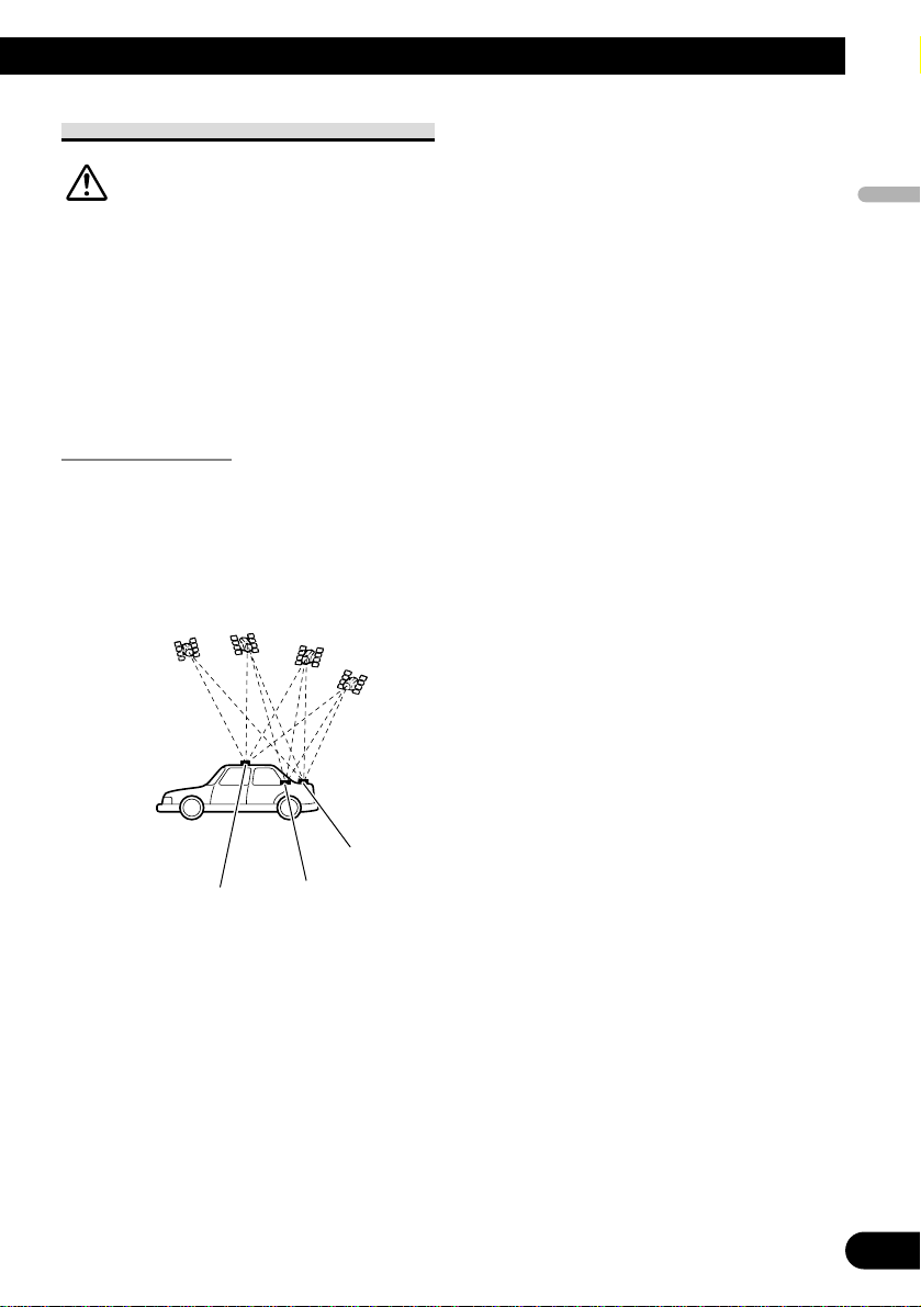
Installation notes
• The antenna should be installed on a level
surface where radio waves will be blocked
as little as possible. Radio waves cannot be
received by the antenna if reception from
the satellite is blocked.
Installation on the vehicle roof or trunk lid is
recommended to optimise reception.
• When installing the GPS antenna inside the
vehicle, be sure to use the metal sheet
provided with your system. If this is not
used, the reception sensitivity will be poor.
• Do not cut the accessory metal sheet. This
would reduce the sensitivity of the GPS
antenna.
• Take care not to pull the antenna lead when
removing the GPS antenna. The magnet
attached to the antenna is very powerful, and
the lead may become detached.
• The GPS antenna is installed with a magnet.
When installing the GPS antenna, be careful
not to scratch the vehicle body.
• When installing the GPS antenna on the outside of the vehicle, always put it in the vehicle when going through an automatic vehicle wash. If it is left on the outside it may be
knocked off and scratch the vehicle body.
• Do not paint the GPS antenna, as this may
affect its performance.
Trunk lid
Roof
Rear shelf
Page 14
13
Installation
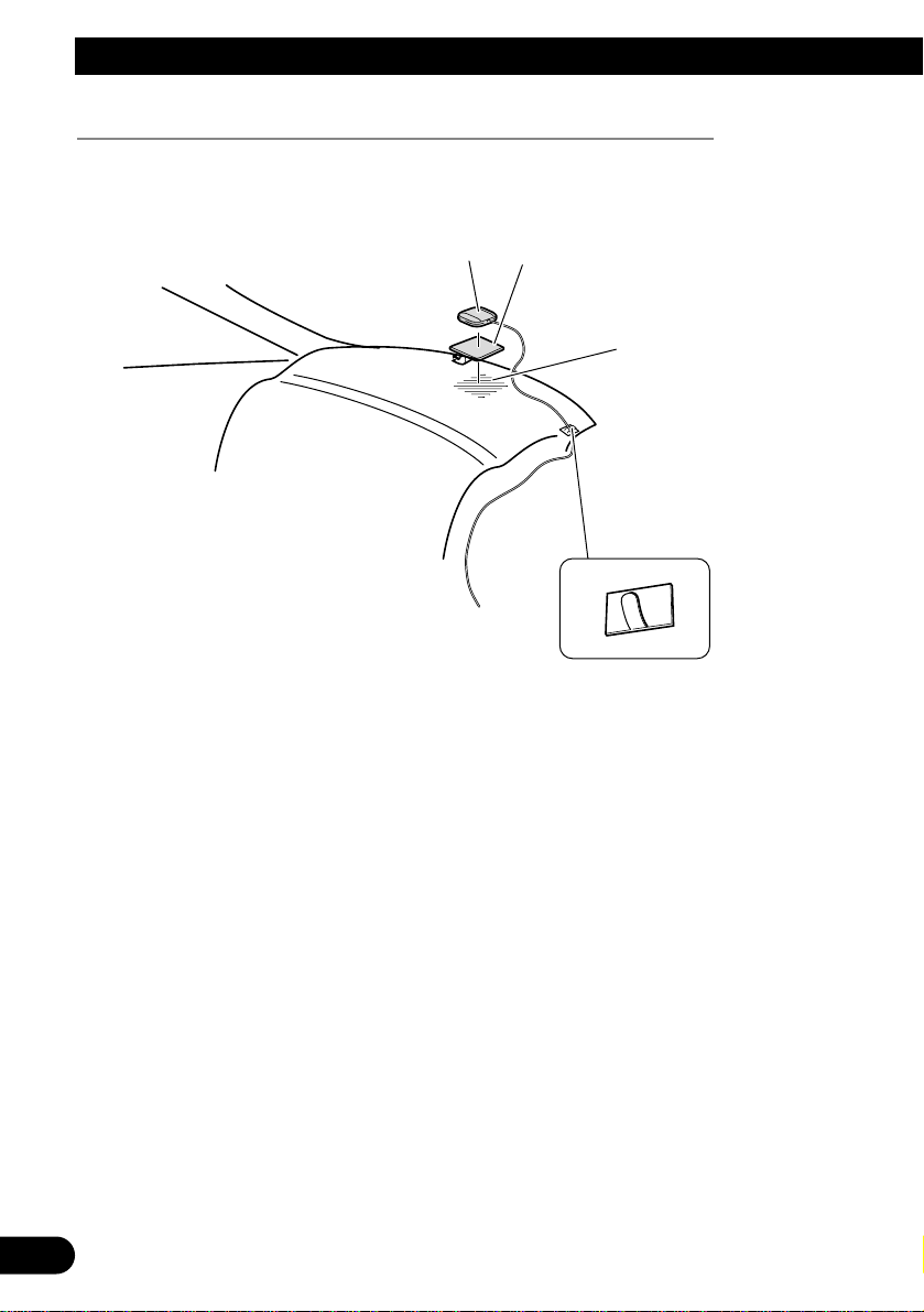
When installing the antenna inside the vehicle (on the rear shelf)
Affix the metal sheet on as level a surface as possible where the GPS antenna faces the
window. Place the GPS antenna on the metal sheet. (The GPS antenna is fastened with its
magnet.)
Note:
• When attaching the metal sheet, do not cut it into small pieces.
• Some models use window glass that does not allow signals from GPS satellites to pass through. On
such models, install the GPS antenna on the outside of the vehicle.
GPS antenna
Metal sheet
Peel off the protective sheet.
Make sure the surface is free of
moisture, dust, grime, oil, etc.,
before affixing the metal sheet.
Note:
• The metal sheet contains a
strong adhesive which may
leave a mark on the surface
if it is removed.
Clamps
Use clamps to secure the
lead where necessary inside
the vehicle.
Page 15
14
English
Español
Deutsch
Français
Italiano
Nederlands
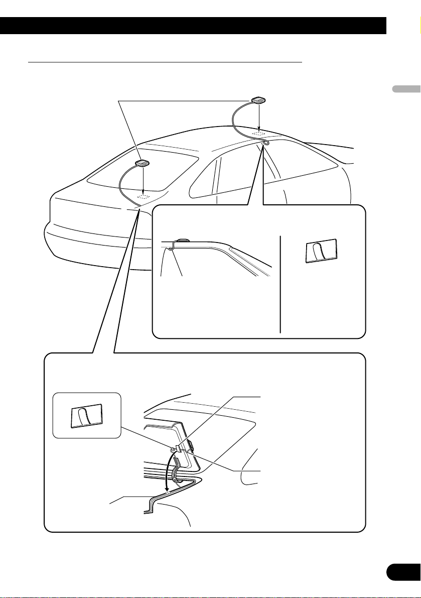
When installing the antenna outside the vehicle (on the body)
Put the GPS antenna in a position as level as possible, such as on the roof or trunk lid. (The
GPS antenna is fastened with a magnet.)
GPS antenna
When routing the lead in from the top of the
door
Clamps
Use clamps to secure
the lead where necessary inside the
vehicle.
Make a U-shaped loop in the lead
on the outside to prevent rainwater
from flowing along the lead into
the interior of the vehicle.
When routing the lead in from inside the trunk
Clamps
Use clamps to secure the
lead where necessary
inside the vehicle.
Make a U-shaped loop in the
lead outside the rubber packing to prevent rainwater from
flowing along the lead into
the interior of the vehicle.
Waterproof pad
Make sure the waterproof
pad contacts the top of the
rubber packing.
Rubber packing
Page 16

1
Contenido
Conexión de las unidades ........................ 2
INSTRUCCIONES DE SEGURIDAD
IMPORTANTES ........................................ 2
Conexión del sistema ........................................ 5
Conexión de cable de alimentación (1) ............ 6
Conexión de cable de alimentación (2) ............ 7
Instalación .................................................. 9
Protección contra la interferencia
electromagnética ........................................ 9
Instalación de esta unidad .............................. 11
Instalación de la antena GPS .......................... 12
Page 17

English
Español
Deutsch
Français
Italiano
Nederlands
Conexión de las unidades
2
INSTRUCCIONES DE SEGURIDAD
IMPORTANTES
Antes de utilizar su Procesador de
Dinámica de Vehículo, asegúrese de leer y
de entender completamente la siguiente
información de seguridad.
1 Lea este manual atentamente antes
de operar su Procesador de
Dinámica de Vehículo.
2 Guarde este manual a mano como
una referencia para futuras
consultas.
3 Tenga especial atención a todas las
advertencias en este manual y siga
las instrucciones cuidadosamente.
4 No instale la pantalla donde pueda
(i) obstruir la visión del conductor,
(ii) perjudicar el rendimiento de
cualquier sistema de operación o
funciones de seguridad del vehículo,
incluyendo los air bags, botón de la
luz de peligro, o (iii) perjudicar la
habilidad del conductor para operar
el vehículo con seguridad.
5 Como con cualquier accesorio en el
interior de su vehículo, la pantalla
no debe distraer su atención de la
operación segura del vehículo.
Cuando encuentre dificultad en
operar al operar el sistema o leer la
pantalla, estacione el vehículo con
seguridad antes de hacer ajustes.
6 No intente instalar o reparar su
Procesador de Dinámica de
Vehículo usted mismo. La
instalación o servicio del Procesador
de Dinámica de Vehículo por
personas sin entrenamiento y
experiencia en equipos electrónicos
y accesorios de automóvil puede ser
peligroso y puede exponerle al
riesgo de descarga eléctrica u otros
peligros, y también puede causar
daños al sistema que no están
cubiertos por la garantía.
7 Acuérdese de utilizar siempre el
cinturón de seguridad mientras
conduce el vehículo. En el caso de
un accidente, sus lesiones pueden
ser considerablemente más graves si
su cinturón de seguridad no está
abrochado adecuadamente.
8 Para aumentar la seguridad, ciertas
funciones se desactivan a menos que
se aplique el freno de
estacionamiento.
Page 18

3
Conexión de las unidades
ADVERTENCIA:
• Para evitar el riesgo de accidente y
violación potencial de las leyes
aplicables, no se deben utilizar nunca
ciertas funciones de esta unidad
mientras se conduce el vehículo.
Igualmente, las pantallas traseras no
deben ubicarse donde presenten una
distracción visible al conductor.
• En algunos países o estados, puede que
sea ilegal la visualización de las
imágenes en una pantalla dentro de un
vehículo, aún por los pasajeros. Donde
haya tales regulaciones, se debe
obedecerlas.
PRECAUCIÓN:
• PIONEER no recomienda que usted
mismo instale o intente reparar su
Procesador de Dinámica de Vehículo.
La instalación o servicio del producto
puede exponerle al riesgo de descarga
eléctrica u otros peligros. Solicite toda la
instalación y servicio de su Procesador
de Dinámica de Vehículo al personal de
servicio autorizado de Pioneer.
• Fije todo el cableado con abrazaderas
de cable o con cinta eléctrica. No permita que cualquier hilo desnudo permanezca expuesto.
• No taladre un agujero en el compartimiento del motor para conectar el
cable amarillo de la unidad a la batería
del vehículo. La vibración del motor
puede eventualmente causar el deterioro
del aislamiento en el punto donde el hilo
pasa del compartimiento de pasajeros al
compartimiento del motor. Tenga especial cuidado al fijar el hilo en este punto.
• Es extremamente peligroso permitir que
el cable de la antena GPS se enrolle
alrededor de la columna de la dirección
o palanca de cambio. Asegúrese de
instalar la unidad de manera que no
obstruya la conducción del vehículo.
• Asegúrese de que los hilos no interfieran
con las piezas móviles del vehículo,
como la palanca de cambio, freno de
estacionamiento o mecanismo de
deslizamiento de los asientos.
• No acorte ningún hilo. De lo contrario,
el circuito de protección podría dejar de
funcionar adecuadamente.
Page 19
English
Español
Deutsch
Français
Italiano
Nederlands
4
Nota:
• Esta unidad es para vehículos con una batería de
12 voltios y conexión a tierra negativa. Antes de
instalarla en un vehículo recreativo, camioneta o
autobús, verifique el voltaje de la batería.
• Para evitar cortocircuitos en el sistema eléctrico,
asegúrese de desconectar el cable ≠ de la batería
antes de iniciar la instalación.
• Consulte el manual del propietario para los
detalles acerca de la conexión del amplificador de
potencia y de otras unidades y, a continuación,
haga las conexiones correctamente.
• Fije el cableado con abrazaderas de cable o con
cinta adhesiva. Para proteger el cableado,
envuélvalo con cinta adhesiva donde el cableado
se apoya sobre piezas metálicas.
• Encamine y fije el cableado de manera que no
toque las piezas móviles como el cambio de
marchas, freno de mano y rieles de los asientos.
No encamine el cableado en lugares que se
quedan calientes, como cerca de la salida del
calentador. El derretimiento o daño de los hilos
crea el peligro de cortocircuitos a través de la
carrocería del vehículo.
• No pase el cable amarillo a través de un agujero
en el compartimiento del motor para conectar la
batería. Esto dañará el aislamiento del cable y
causará un cortocircuito muy peligroso.
• No corte el cable de la antena GPS para acortarlo
ni utilice una extensión para alargarlo. Modificar
el cable de la antena podría causar un cortocircuito o fallo de funcionamiento.
• No acorte ningún hilo. De lo contrario, el circuito
de protección podría dejar de funcionar cuando
debería.
• No suministre nunca energía a otros equipos
cortando el aislamiento del cable de alimentación
de la unidad y haciendo una derivación con otro
hilo. La capacidad de corriente del hilo se
excederá, causando un sobrecalentamiento.
• Cuando reemplace el fusible, asegúrese de utilizar
solamente un fusible del régimen indicado en el
portafusible.
• Si se instala esta unidad en un vehículo que no
tiene una posición ACC (accesorio) en el
interruptor de encendido, se debe conectar el
cable rojo de la unidad al terminal acoplado con
las operaciones de encendido/apagado del
interruptor de encendido. Si no se hace esto, la
batería del vehículo puede descargarse cuando
esté fuera del vehículo por varias horas.
Sin posición ACCPosición ACC
• Los cables para este producto y los cables para
otros productos pueden tener colores diferentes
aunque tengan la misma función. Cuando
conecte este producto a otro producto, consulte
los manuales suministrados de ambos los
productos y conecte los cables que tienen la
misma función.
C
C
A
O
F
N
F
O
S
T
A
R
T
O
F
N
F
O
S
T
A
R
T
Page 20
5
Conexión de las unidades
Conexión del sistema
Esta unidad
Altavoz de guía
(por ejemplo, CD-TS37GP)
(vendido separadamente)
Antena GPS
Amarillo
Negro
Cable de 26 clavijas
Pantalla
(vendida separadamente)
Videograbadora con toma
de entrada RCA
(vendida separadamente)
A la entrada de vídeo
Cable RCA
(vendido separadamente)
5 m
6 m
El terminal de salida del altavoz de guía de esta
unidad se utiliza en la siguiente condición:
Cuando se conecta a esta unidad un procesador de
canales múltiples y una pantalla que no tienen un
terminal de salida de altavoz.
Nota:
• En los siguientes casos, puede que las imágenes no se visualicen apropiadamente en el
monitor/videograbadora:
- Cuando no se esté visualizando la imagen
V.D.P. emitida por esta unidad en el monitor
frontal.
- Cuando se conecta un
monitor/videograbadora que tenga un formato de salida de vídeo incompatible con el ter-
minal VIDEO OUT de esta unidad.
Para los detalles, consulte el manual de
operación.
Page 21
6
English
Español
Deutsch
Français
Italiano
Nederlands
Conexión de cable de alimentación (1)
Fusible (4 A)
Esta unidad
Resistor de fusible
Amarillo
Al terminal siempre suministrado con
alimentación independientemente de la
posición del interruptor de encendido.
Rojo
Al terminal eléctrico controlado por la
operación de encendido/apagado del
interruptor de encendido (12 V DC).
Negro (masa)
A la carrocería del vehículo (metal).
Blanco/negro
Al polo negativo del cable del altavoz
frontal izquierdo.
Gris/negro
Al polo negativo del cable del altavoz
frontal derecho.
Page 22
7
Conexión de las unidades
Conexión de cable de alimentación (2)
Rosado
Se utiliza para detectar la distancia de viaje del
vehículo. Siempre conecte el circuito de detección
de velocidad del vehículo. Dejar de hacer esta
conexión aumentará los errores en el localizador
GPS.
ADVERTENCIA:
LA CONEXIÓN INCORRECTA PUEDE CAUSAR
SERIOS DAÑOS O LESIONES, INCLUYENDO
UNA DESCARGA ELÉCTRICA O LA
INTERFERENCIA CON LA OPERACIÓN DEL
SISTEMA ANTIBLOQUEO DE FRENADA,
TRANSMISIÓN AUTOMÁTICA E INDICACIÓN
DEL VELOCÍMETRO DEL VEHÍCULO.
Nota:
• La posición del circuito de detección de velocidad depende del modelo del vehículo. Para los
detalles, consulte su revendedor Pioneer autorizado o un profesional de instalación.
Rosado/negro
No se usa.
Page 23
English
Español
Deutsch
Français
Italiano
Nederlands
8
Esta unidad
Violeta/blanco
De los dos hilos conectados a la luz trasera, conecte el
hilo en el cual el voltaje cambia cuando la palanca de
cambio está en la posición REVERSE (R). Si no se
conecta, esta unidad no funcionará correctamente.
Resistor de fusible
Método de conexión
1. Fije el cable. 2. Fije firmemente con
alicates de punta
fina.
Verde claro
Se utiliza para detectar el estado de encendido/apagado
del freno de estacionamiento. Se debe conectar este cable
al lado de suministro de energía del interruptor del freno
de estacionamiento.
Interruptor del
freno de estacionamiento
Lado del suministro
de energía
Lado de masa
Nota:
• La posición del interruptor
del freno de estacionamiento
depende del modelo del
vehículo. Para los detalles,
consulte el manual del propietario del vehículo o el
revendedor.
ADVERTENCIA:
EL CABLE VERDE CLARO EN EL CONECTOR DE
ENERGÍA ESTÁ DISEÑADO PARA DETECTAR EL
ESTADO DE ESTACIONAMIENTO Y DEBE
CONECTARSE AL LADO DE SUMINISTRO DE
ENERGÍA DEL INTERRUPTOR DEL FRENO DE
ESTACIONAMIENTO. UNA CONEXIÓN O USO
INCORRECTO DE ESTE CABLE PUEDE VIOLAR
LA LEY APLICABLE Y PUEDE CAUSAR SERIAS
LESIONES Y DAÑOS.
Page 24
9
Instalación
Nota:
• Antes de realizar una instalación final de la
unidad, conecte el cableado temporalmente para
comprobar que las conexiones estén correctas y
que el sistema esté funcionando adecuadamente.
• Utilice solamente las piezas incluidas con la
unidad para asegurar la instalación correcta. El
uso de piezas no autorizadas puede causar un
fallo de funcionamiento.
• Consulte su revendedor más cercano si se
requiere taladrar agujeros o hacer otras
modificaciones del vehículo para la instalación.
• Instale la unidad donde no interfiera con el
conductor y no pueda herir los pasajeros debido a
una parada brusca, como en una parada de
emergencia.
• Cuando monte esta unidad, asegúrese de que
ningún de los cables estén atrapados entre esta
unidad y las piezas o accesorios alrededor.
• No monte esta unidad cerca de la salida del
calentador, donde sería afectada por el calor, o
cerca de las puertas, donde la lluvia podría
salpicar en la misma.
• Antes de taladrar cualquier agujero, siempre
verifique la parte trasera donde desea taladrar los
agujeros. No taladre en la línea de gas, línea del
freno, cableado eléctrico u otras partes
importantes.
• Si se instala esta unidad en el compartimiento de
pasajeros, fíjela firmemente de modo que no se
suelte mientras el vehículo esté en movimiento, y
cause lesiones o un accidente.
• Si se instala esta unidad debajo de un asiento
delantero, asegúrese de que no obstruya el
movimiento del asiento. Encamine todos los hilos
y cables cuidadosamente alrededor del
mecanismo de deslizamiento de modo que no se
atrapen o se compriman en el mecanismo y
causen un corto-circuito.
• No instale esta unidad en el tablero que cubre el
neumático de repuesto u otros lugares que sean
sujetos a vibraciones.
• Cuando instale esta unidad, elija una posición que
asegure que no habrá contacto con el equipaje.
El impacto de un objeto pesado o choque
repentino en esta unidad afectará adversamente la
visualización precisa de la ubicación actual del
vehículo.
• Evite instalar esta unidad en lugares donde la
misma interferirá con la carga y descarga del
neumático de repuesto, gato, herramientas, etc.
• Instale esta unidad horizontalmente en una
superficie dentro de una tolerancia de +30º a –30º
(dentro de 5º a la izquierda o derecha de la
dirección de viaje del vehículo). Una instalación
inadecuada de la unidad en una superficie
inclinada además de las tolerancias especificadas
aumenta el potencial para errores en la
visualización de la ubicación, y podría causar un
rendimiento reducido de la visualización.
Protección contra la interferencia
electromagnética
Para evitar interferencias, ajuste los
siguientes ítems lo más lejos posible
de esta unidad, otros hilos y cables.
- Antena de TV y su cable
- Antena de radio y su cable
- Antena GPS y su cable
Además, debe posicionar o encaminar
cada cable de antena lo más lejos
posible de los otros cables de antena.
No enlace, posicione o encamine
juntos, ni cruce los cables.
El ruido electromagnético aumentará
el potencial para errores en la
visualización de ubicación.
5°
30°
30°
Page 25
English
Español
Deutsch
Français
Italiano
Nederlands
10
PRECAUCIÓN:
• Instale con los lados izquierdo y derecho de esta unidad perpendicular o
paralelo a la dirección de viaje del vehículo. No instale diagonalmente a la
dirección de viaje del vehículo, o la ubicación actual se visualizará incorrectamente.
• Asegúrese de instalar esta unidad en el piso con el lado de la serigrafía hacia
arriba. Esta unidad sólo funcionará correctamente en esta posición.
Dirección hacia delante/
atrás del vehículo
Page 26
11
Instalación
Instalación de esta unidad
1. Fije las ménsulas laterales a esta
unidad.
Cuando se instala esta unidad en el piso o
en el tablero de instalación debajo del
asiente del pasajero, etc., las ménsulas laterales deben estar fijadas a esta unidad.
Utilice los siguientes agujeros en
las ménsulas laterales.
Si se desplazan las posiciones de
las placas laterales paralelamente,
también se puede utilizar otros
agujeros que coinciden con los
agujeros en esta unidad.
Cuando se instala esta unidad debajo
del asiento del pasajero, etc., utilice el
tablero de instalación.
2. Decida la posición de instalación, y
taladre los agujeros.
3. Fije firmemente utilizando los
tornillos autorroscantes.
Taladre agujeros entre
4 y 4,5 mm de
diámetro.
Tablero de
instalación
Marque las posiciones
para taladrar los agujeros.
Tornillo autorroscante
(6 × 16 mm)
Esta unidad
Tornillo con
arandela (4 × 8 mm)
Ménsula lateral
Page 27

12
English
Español
Deutsch
Français
Italiano
Nederlands
Instalación de la antena GPS
PRECAUCIÓN:
• No corte el cable de la antena
GPS para acortarlo ni utilice
una extensión para alargarlo.
Modificar el cable de antena
podría causar un corto-circuito o
fallo de funcionamiento, y dañar
el producto permanentemente.
Notas acerca de la instalación
• Se debe instalar la antena en una superficie
nivelada, donde las ondas de radio queden
bloqueadas lo menos posible. La antena no
podrá recibir las ondas de radio cuando la
recepción del satélite esté bloqueada.
Se recomienda la instalación en el techo o
tapa de portaequipaje del vehículo para
optimizar la recepción.
• Cuando instale la antena GPS dentro del
vehículo, asegúrese de utilizar la hoja
metálica suministrada con su sistema. Si no
se utiliza esto, la sensibilidad de recepción
será mala.
• No corte la hoja metálica suministrada. Esto
reduciría la sensibilidad de la antena GPS.
• Tenga cuidado en no tirar del cable de la
antena cuando saque la antena GPS. El
electroimán fijado a la antena es muy
potente, y el cable puede soltarse.
• La antena GPS se instala con un
electroimán. Cuando instale la antena GPS,
tenga cuidado en no arañar la carrocería del
vehículo.
• Cuando instale la antena GPS en el lado
exterior del vehículo, siempre colóquela
dentro del vehículo cuando fuera pasar por
un Car Wash. Si se deja la antena en el lado
de fuera, puede que se suelte y arañe la
carrocería del vehículo.
• No pinte la antena GPS, ya que esto puede
afectar su rendimiento.
Tapa del
portaequipaje
Techo
Bandeja trasera
Page 28

13
Instalación
Cuando instale la antena dentro del vehículo (en la bandeja trasera)
Fije la hoja metálica lo más nivelado posible, donde la antena GPS quede hacia la ventana.
Coloque la antena GPS en la hoja metálica. (La antena GSP se fija con su electroimán.)
Nota:
• Cuando fije la hoja metálica, no la corte en piezas pequeñas.
• Algunos modelos utilizan un vidrio de ventana que no permite el pasaje de las señales de satélites
GPS. En tales modelos, instale la antena GPS en el lado exterior del vehículo.
Antena GPS
Hoja metálica
Quite la hoja protectora.
Asegúrese de que la superficie
esté libre de humedad, polvo,
suciedad, aceite, etc., antes de
fijar la hoja metálica.
Nota:
• La hoja metálica contiene un
adhesivo fuerte que puede
dejar una marca en la
superficie si se la quita.
Abrazaderas
Utilice abrazaderas para fijar
el cable donde sea necesario
dentro del vehículo.
Page 29

14
English
Español
Deutsch
Français
Italiano
Nederlands
Cuando instale la antena en el lado exterior del vehículo (en la carrocería)
Coloque la antena GPS en una posición lo más nivelada posible, como en el techo o tapa
del portaequipaje. (La antena GSP se fija con un electroimán.)
Antena GPS
Cuando encamine el cable desde la parte
superior de la puerta
Abrazaderas
Utilice abrazaderas
para fijar el cable
donde sea necesario
dentro del vehículo.
Haga un enlace en forma de “U”
en el cable en el lado exterior para
evitar que el agua de la lluvia
fluya a lo largo del cable hacia el
interior del vehículo.
Cuando encamine el cable desde el interior del portaequipaje
Abrazaderas
Utilice abrazaderas para
fijar el cable donde sea
necesario dentro del
vehículo.
Haga un enlace en forma de
“U” en el cable en el lado
exterior de la empaquetadura
de caucho para evitar que el
agua de la lluvia fluya a lo
largo del cable hacia el
interior del vehículo.
Almohadilla impermeable
Asegúrese de que la
almohadilla impermeable
toque la parte superior de la
empaquetadura de caucho.
Empaquetadura de
caucho
Page 30

1
Inhalt
Anschließen der Geräte .......................... 2
WICHTIGE VORSICHTSMASSNAHMEN .... 2
Anschließen des Systems .................................. 5
Anschließen des Stromkabels (1) ...................... 6
Anschließen des Stromkabels (2) ...................... 7
Installation .................................................. 9
Zum Schutz vor elektromagnetischer
Beeinflussung ............................................ 9
Installieren dieses Gerätes .............................. 11
Installieren der GPS-Antenne .......................... 12
Page 31

English
Español
Deutsch
Français
Italiano
Nederlands
Anschließen der Geräte
2
WICHTIGE
VORSICHTSMASSNAHMEN
Bitte lesen Sie die folgenden
Sicherheitsinformationen vor der
Benutzung Ihres FahrzeugDynamikprozessors durch, um sich
vollkommen mit ihnen vertraut zu machen.
1 Lesen Sie diese Anleitung
vollständig und aufmerksam durch,
bevor Sie Ihren FahrzeugDynamikprozessor in Betrieb
nehmen.
2 Bewahren Sie diese Anleitung für
spätere Bezugnahme griffbereit auf.
3 Achten Sie genau auf alle
Warnungen in dieser Anleitung,
und befolgen Sie die Anweisungen
sorgfältig.
4 Installieren Sie das Display nicht an
einer Stelle, wo es (i) das Blickfeld
des Fahrers beschränken, (ii) die
Funktion irgendeines
Betriebssystems oder
Sicherheitsmerkmals des Fahrzeugs
wie Airbags und Warnlampentasten
beeinträchtigen oder (iii) den
Fahrer bei der sicheren Führung
des Fahrzeugs behindern könnte.
5 Wie jedes andere Zubehör im
Fahrgastraum Ihres Fahrzeugs, so
sollte auch das Display Ihre
Aufmerksamkeit nicht vom sicheren
Betrieb Ihres Fahrzeugs ablenken.
Falls Sie Schwierigkeiten mit der
Bedienung des Systems oder dem
Ablesen des Displays haben, parken
Sie bitte an einem sicheren Ort,
bevor Sie Einstellungen
durchführen.
6 Versuchen Sie nicht, Ihren
Fahrzeug-Dynamikprozessor selbst
zu installieren oder zu warten. Die
Installation oder Wartung des
Fahrzeug-Dynamikprozessors
durch Personen, die nicht im
Umgang mit Elektronikgeräten und
Fahrzeugzubehör geschult oder
bewandert sind, kann gefährlich
sein und könnte Sie der Gefahr
eines elektrischen Schlags oder
anderen Gefahren aussetzen und
Schäden am System verursachen,
die nicht von der Garantie
abgedeckt sind.
7 Bitte denken Sie stets daran, den
Sicherheitsgurt während der Fahrt
anzulegen. Sollten Sie in einen
Unfall verwickelt werden, können
Sie erheblich schwerere
Verletzungen erleiden, wenn Sie
nicht richtig angeschnallt sind.
8 Aus Sicherheitsgründen sind
bestimmte Funktionen deaktiviert,
wenn die Handbremse nicht
angezogen ist.
Page 32

3
Anschließen der Geräte
WARNUNG:
• Um die Gefahr eines Unfalls und eine
mögliche Verletzung geltender Gesetze
zu vermeiden, dürfen bestimmte
Funktionen dieses Gerätes niemals
eingesetzt werden, während das
Fahrzeug in Bewegung ist. Außerdem
dürfen hintere Displays nicht an einer
Stelle angebracht werden, wo sie eine
sichtbare Ablenkung für den Fahrer
darstellen.
• In einigen Ländern oder Staaten ist das
Betrachten von Bildern auf einem
Monitor in einem Fahrzeug untersagt,
auch durch Personen, die das Fahrzeug
nicht steuern. Derartige Vorschriften,
falls zutreffend, müssen befolgt werden.
VORSICHT:
• PIONEER rät davon ab, den FahrzeugDynamikprozessor selbst zu installieren
oder zu warten. Durch die Installation
oder Wartung des Produkts können Sie
der Gefahr eines elektrischen Schlags
oder anderen Gefahren ausgesetzt
werden. Überlassen Sie daher alle
Installations- und Wartungsarbeiten
Ihres Fahrzeug-Dynamikprozessors
autorisiertem Pioneer-Wartungspersonal.
• Sichern Sie alle Kabel mit
Kabelklemmen oder Klebeband. Lassen
Sie keine blanken Drähte ausgesetzt.
• Bohren Sie kein Loch in den
Motorraum, um das gelbe Kabel des
Gerätes an die Fahrzeugbatterie
anzuschließen. Die Motorvibrationen
können dazu führen, dass an der Stelle,
an der das Kabel vom Fahrgastraum in
den Motorraum eintritt, die Isolierung
durchgescheuert wird. Sichern Sie das
Kabel an dieser Stelle mit besonderer
Sorgfalt.
• Achten Sie darauf, dass sich das GPSAntennenkabel nicht um die Lenksäule
oder den Schalthebel wickelt, weil das
sehr gefährlich ist. Installieren Sie das
Gerät so, dass es den Fahrbetrieb nicht
behindert.
• Vergewissern Sie sich, dass Kabel keine
beweglichen Teile des Fahrzeugs, wie
z.B. Schalthebel, Handbremse oder
Sitzverstellung, behindern.
• Verkürzen Sie keine Kabel.
Anderenfalls kann die Funktion der
Schutzschaltung beeinträchtigt werden.
Page 33

English
Español
Deutsch
Français
Italiano
Nederlands
4
Hinweis:
• Dieses Gerät ist für Fahrzeuge mit 12-VoltBatterie und negativer Erdung konzipiert.
Überprüfen Sie die Batteriespannung, bevor Sie
es in ein Campingauto, einen Lkw oder Bus
installieren.
• Um Kurzschlüsse in der elektrischen Anlage zu
vermeiden, klemmen Sie unbedingt das
Massekabel ≠ vor der Installation ab.
• Einzelheiten zum richtigen Anschluss des
Leistungsverstärkers und anderer Geräte
entnehmen Sie bitte der Gebrauchsanweisung.
• Sichern Sie Kabel mit Kabelklemmen oder
Klebeband. Umwickeln Sie Kabel an
Berührungsstellen mit Metallteilen zum Schutz
mit Klebeband.
• Verlegen und sichern Sie alle Kabel so, dass sie
keine beweglichen Teile, wie z.B. Schalthebel,
Handbremse oder Sitzschienen, berühren können.
Verlegen Sie Kabel nicht an Stellen, die heiß
werden können, wie z.B. in der Nähe eines
Warmluftausströmers. Wenn eine Kabelisolierung
schmilzt oder beschädigt ist, besteht die Gefahr
eines Kurzschlusses zu Fahrzeugmasse.
• Führen Sie das gelbe Kabel nicht durch eine
Öffnung in den Motorraum, um den Anschluss an
die Batterie herzustellen. Hierdurch wird die
Leitungsisolierung beschädigt, und ein äußerst
gefährlicher Kurzschluss kann die Folge sein.
• Unterlassen Sie ein Durchschneiden des GPSAntennenkabels, um es zu verkürzen oder zu
verlängern. Eine Veränderung des
Antennenkabels könnte zu einem Kurzschluss
oder einer Funktionsstörung führen.
• Verkürzen Sie keine Kabel. Anderenfalls kann die
Schutzschaltung im Ernstfall versagen.
• Führen Sie niemals Strom einem anderen Gerät
zu, indem Sie die Stromversorgungsleitung des
Geräts abisolieren und die Leitung anzapfen.
Dadurch wird die Belastbarkeit des Kabels
überschritten und eine Überhitzung verursacht.
• Als Ersatzsicherung darf nur eine Sicherung
verwendet werden, deren Nennstrom mit der
Angabe am Sicherungshalter übereinstimmt.
• Falls dieses Gerät in ein Fahrzeug eingebaut wird,
dessen Zündschalter keine Position ACC
(Zubehör) besitzt, muss das rote Kabel des
Gerätes an eine Klemme angeschlossen werden,
die mit der EIN/AUS-Funktion des Zündschalters
gekoppelt ist. Anderenfalls kann sich die
Fahrzeugbatterie entladen, wenn das Fahrzeug
mehrere Stunden lang stehen gelassen wird.
Ohne Position ACCPosition ACC
• Die Kabel für dieses Produkt und diejenigen für
andere Produkte können unterschiedliche Farben
aufweisen, selbst wenn sie die gleiche Funktion
haben. Nehmen Sie beim Anschließen dieses
Produkts an ein anderes Produkt die
mitgelieferten Anleitungen beider Produkte zur
Hand, und schließen Sie Kabel der gleichen
Funktion an.
C
C
A
O
F
N
F
O
S
T
A
R
T
O
F
N
F
O
S
T
A
R
T
Page 34

5
Anschließen der Geräte
Anschließen des Systems
Dieses Gerät
Führungslautsprecher
(z.B. CD-TS37GP)
(im Handel erhältlich)
GPS-Antenne
Gelb
Schwarz
26-poliges Kabel
Anzeigegerät
(im Handel erhältlich)
Videorekorder mit
RCA-Eingangsbuchse
(im Handel erhältlich)
An Video-Eingang
RCA-Kabel
(im Handel erhältlich)
5 m
6 m
Die Führungslautsprecher-Ausgangsbuchse dieses
Gerätes wird unter folgender Bedingung verwendet:
Wenn ein Mehrkanalprozessor und ein
Anzeigegerät ohne Lautsprecher-Ausgangsbuchse
an dieses Gerät angeschlossen werden.
Hinweis:
• In den folgenden Fällen werden Bilder
möglicherweise nicht korrekt auf dem
Display/Videorecorder angezeigt:
- Wenn das von diesem Gerät ausgegebene
V.D.P.-Bild nicht auf dem
Frontplattendisplay angezeigt wird.
- Wenn ein Display/Videorecorder
angeschlossen wird, dessen
Videoausgangsformat nicht mit dem
Anschluss VIDEO OUT dieses Gerätes
kompatibel ist.
Weitere Einzelheiten entnehmen Sie bitte der
Bedienungsanleitung.
Page 35

6
English
Español
Deutsch
Français
Italiano
Nederlands
Anschließen des Stromkabels (1)
Sicherung (4 A)
Dieses Gerät
Sicherungswiderstand
Gelb
An eine Klemme, die ungeachtet der
Zündschalterstellung stets Strom führend ist.
Rot
An eine mit EIN/AUS des Zündschalters
(12 V Gleichstrom) gekoppelte Klemme.
Schwarz (Masse)
An Fahrzeugkarosserie (Metall).
Weiß/Schwarz
An Minuspol des linken
Frontlautsprecherkabels.
Grau/Schwarz
An Minuspol des rechten
Frontlautsprecherkabels.
Page 36

7
Anschließen der Geräte
Anschließen des Stromkabels (2)
Rosa
Dient zur Erkennung der Fahrstrecke des Fahrzeugs.
Schließen Sie stets die Geschwindigkeitserkennungsschaltung
des Fahrzeugs an. Eine Unterlassung dieses Anschlusses führt
zu einer Zunahme der Fehler im GPS-Locator.
WARNUNG:
FALSCHER ANSCHLUSS KANN SCHWERE
SACHSCHÄDEN ODER VERLETZUNGEN,
EINSCHLIESSLICH STROMSCHLAG, UND
BEEINTRÄCHTIGUNG DER FUNKTION DES
ANTIBLOCKIERSYSTEMS, DES AUTOMATIKGETRIEBES
UND DER TACHOMETERANZEIGE DES FAHRZEUGS
VERURSACHEN.
Hinweis:
• Die Lage der Geschwindigkeitserkennungsschaltung ist
je nach Fahrzeugmodell unterschiedlich. Fragen Sie
bitte Ihren autorisierten Pioneer-Händler oder einen
Elektroinstallateur nach Einzelheiten.
Rosa/Schwarz
Nicht benutzt.
Page 37

English
Español
Deutsch
Français
Italiano
Nederlands
8
Dieses Gerät
Violett/Weiß
Schließen Sie von den beiden mit der Rückfahrleuchte verbundenen
Kabeln dasjenige an, dessen Spannung sich ändert, wenn sich der
Schalthebel in der Position REVERSE (R) befindet. Wird dieser
Anschluss ausgelassen, funktioniert dieses Gerät nicht richtig.
Sicherungswiderstand
Anschlussverfahren
1. Das Kabel
einklemmen.
2. Mit einer Nadelzange
festklemmen.
Hellgrün
Dient zur Erkennung des EIN/AUS-Zustands der
Handbremse. Dieses Kabel muss an die
Stromversorgungsseite des Handbremsschalters
angeschlossen werden.
Handbremsschalter
Stromversorgungsseite
Masseseite
Hinweis:
• Die Lage des
Handbremsschalters ist je
nach Fahrzeugmodell
unterschiedlich. Um
Einzelheiten zu erfahren,
konsultieren Sie die
Bedienungsanleitung des
Fahrzeugs oder Ihren
Händler.
WARNUNG:
DAS HELLGRÜNE KABEL AM STROMANSCHLUSS
DIENT ZUR ERKENNUNG DES PARKZUSTANDS
UND MUSS MIT DER STROMVERSORGUNGSSEITE
DES HANDBREMSSCHALTERS VERBUNDEN
WERDEN. FALSCHER ANSCHLUSS ODER
GEBRAUCH DIESES KABELS KANN GEGEN DIE
GELTENDEN GESETZE VERSTOßEN UND
SCHWERE VERLETZUNGEN ODER
SACHSCHÄDEN VERURSACHEN.
Page 38

9
Installation
Hinweis:
• Bevor Sie das Gerät endgültig einbauen,
schließen Sie die Kabel provisorisch an und
vergewissern Sie sich, dass alle Anschlüsse
stimmen und das System richtig funktioniert.
• Um richtige Installation zu gewährleisten,
verwenden Sie nur die mit dem Gerät gelieferten
Teile. Durch den Gebrauch nicht zugelassener
Teile können Funktionsstörungen verursacht
werden.
• Setzen Sie sich mit einem Händler in Ihrer Nähe
in Verbindung, wenn die Installation das Bohren
von Löchern oder andere Modifikationen am
Fahrzeug erfordert.
• Installieren Sie das Gerät so, dass es den Fahrer
nicht behindern und im Falle einer Notbremsung
den Beifahrer nicht verletzen kann.
• Vergewissern Sie sich, dass bei der Installation
keine Leitung zwischen dem Gerät und
umgebenden Metallteilen oder Beschlägen
eingeklemmt wird.
• Installieren Sie das Gerät nicht in der Nähe eines
Warmluftausströmers, wo es durch Wärme
beeinträchtigt werden könnte, oder in der Nähe
der Türen, wo es bei Regen Feuchtigkeit
ausgesetzt sein könnte.
• Bevor Sie ein Montageloch bohren, prüfen Sie
stets nach, was sich hinter der vorgesehenen
Bohrstelle befindet. Achten Sie darauf, nicht in
eine Kraftstoffleitung, Bremsleitung, ein
elektrisches Kabel oder andere wichtige Teile zu
bohren.
• Falls dieses Gerät im Fahrgastraum installiert
wird, muss es sicher verankert werden, sodass es
sich während der Fahrt nicht lösen und
Verletzungen bzw. einen Unfall verursachen
kann.
• Falls dieses Gerät unter einem Vordersitz
installiert wird, vergewissern Sie sich, dass die
Sitzverstellung nicht behindert wird. Verlegen Sie
alle Kabel und Leitungen sorgfältig um den
Verschiebemechanismus, sodass sie sich nicht
daran verfangen oder eingeklemmt werden
können, um einen Kurzschluss zu vermeiden.
• Installieren Sie dieses Gerät nicht auf der
Reserveradabdeckung oder an anderen Stellen,
die Vibrationen ausgesetzt sind.
• Wählen Sie für die Installation dieses Gerätes
eine Position, an der es nicht mit Gepäck in
Berührung kommen kann. Der Aufprall eines
schweren Gewichts oder eine plötzliche
Erschütterung dieses Gerätes beeinträchtigt die
genaue Anzeige der aktuellen Fahrzeugposition.
• Vermeiden Sie die Installation dieses Gerätes an
Orten, wo es das Ein- und Ausladen des
Reserverads, des Wagenhebers, der Werkzeuge
usw. beeinträchtigt.
• Installieren Sie dieses Gerät horizontal auf einer
Fläche innerhalb einer Toleranz von +30º bis
–30º (innerhalb von 5º zur Linken und Rechten
der Fahrtrichtung). Die Installation des Gerätes
auf einer Fläche, die stärker als diese Toleranzen
geneigt ist, erhöht das Potenzial für Fehler in der
Standortanzeige und könnte eine
Verschlechterung der Anzeigegenauigkeit
verursachen.
Zum Schutz vor
elektromagnetischer Beeinflussung
Um Störbeeinflussung zu verhüten, sind
die folgenden Teile möglichst weit von
diesem Gerät und anderen Kabeln oder
Leitungen entfernt zu halten:
- TV-Antenne und Antennenkabel
- Radioantenne und Antennenkabel
- GPS-Antenne und Antennenkabel
Außerdem sollten Sie jedes
Antennenkabel so weit wie möglich von
anderen Antennenkabeln entfernt
verlegen.
Unterlassen Sie Bündeln, gemeinsames
Verlegen oder Überschneiden der Kabel.
Derartiges elektromagnetisches
Rauschen erhöht das Potenzial für
Fehler in der Standortanzeige.
5°
30°
30°
Page 39

English
Español
Deutsch
Français
Italiano
Nederlands
10
VORSICHT:
• Installieren Sie das Gerät quer oder längs zur Fahrtrichtung. Wird das
Gerät schräg zur Fahrtrichtung installiert, wird der aktuelle Standort falsch
angezeigt.
• Installieren Sie dieses Gerät so auf dem Boden, dass die Siebdruckseite oben
liegt. Nur in dieser Position funktioniert das Gerät einwandfrei.
Vorder-/Rückseite
des Fahrzeugs
Page 40

11
Installation
Installieren dieses Gerätes
1. Befestigen Sie die Seitenhalterungen
am Gerät.
Wenn dieses Gerät auf dem Boden oder
der Installationsplatte unter dem
Beifahrersitz usw. installiert wird, sollten
die Seitenhalterungen am Gerät befestigt
werden.
Verwenden Sie die folgenden
Löcher in den Seitenhalterungen.
Wenn Sie die Seitenplatten parallel
verschieben, können Sie auch
andere Löcher verwenden, die sich
mit den Löchern im Gerät decken.
Wenn dieses Gerät unter dem Beifahrersitz
usw. installiert wird, verwenden Sie die
Installationsplatte.
2. Legen Sie die Installationsposition
fest, und bohren Sie die Löcher.
3. Sichern Sie das Gerät einwandfrei
mit Schneidschrauben.
Löcher von 4 bis 4,5 mm
Durchmesser bohren.
Installationsplatte
Die Positionen für die
Löcher markieren.
Schneidschraube
(6
× 16 mm)
Dieses Gerät
Bundschraube
(4 × 8 mm)
Seitenhalterung
Page 41

12
English
Español
Deutsch
Français
Italiano
Nederlands
Installieren der GPS-Antenne
VORSICHT:
• Unterlassen Sie ein
Durchschneiden des GPSAntennenkabels, um es zu
verkürzen oder zu verlängern.
Eine Veränderung des
Antennenkabels könnte zu einem
Kurzschluss oder einer
Funktionsstörung führen und
bleibenden Schaden am Produkt
verursachen.
Installationshinweise
• Die Antenne sollte auf einer ebenen Fläche
installiert werden, wo die Funkwellen so
wenig wie möglich blockiert werden. Die
Funkwellen können nicht von der Antenne
empfangen werden, wenn der
Satellitenempfang blockiert wird.
Um den Empfang zu optimieren, ist die
Installation auf dem Dach oder dem
Kofferraumdeckel des Fahrzeugs zu
empfehlen.
• Wenn Sie die GPS-Antenne im
Fahrzeuginneren installieren, verwenden Sie
unbedingt die mit Ihrem System gelieferte
Metallplatte. Wird diese Platte nicht
verwendet, verschlechtert sich die
Empfangsempfindlichkeit.
• Unterlassen Sie ein Schneiden der
mitgelieferten Metallplatte, weil dadurch die
Empfindlichkeit der GPS-Antenne reduziert
werden würde.
• Achten Sie beim Abnehmen der GPSAntenne darauf, dass Sie das Antennenkabel
nicht herausziehen. Der an der Antenne
angebrachte Magnet ist sehr stark, und das
Kabel könnte sich lösen.
• Die GPS-Antenne wird mit einem Magneten
angebracht. Achten Sie bei der Anbringung
der GPS-Antenne darauf, dass Sie die
Karosserie des Fahrzeugs nicht verkratzen.
• Wenn die GPS-Antenne an der Außenseite
des Fahrzeugs installiert ist, nehmen Sie sie
stets ab, bevor Sie das Fahrzeug in einer
automatischen Waschanlage waschen
lassen. Bleibt sie am Fahrzeug angebracht,
besteht die Gefahr, dass sie abgeschlagen
wird und die Karosserie verkratzt.
• Unterlassen Sie ein Lackieren der GPSAntenne, weil dadurch ihre Leistung
beeinträchtigt werden kann.
Kofferraumdeckel
Dach
Heckablage
Page 42

13
Installation
Installation der Antenne im Fahrzeuginneren (auf der Heckablage)
Befestigen Sie die Metallplatte auf einer möglichst ebenen Fläche, sodass die GPSAntenne zum Fenster gerichtet ist. Setzen Sie die GPS-Antenne auf die Metallplatte.
(Die GPS-Antenne wird mit ihrem Magneten befestigt.)
Hinweis:
• Schneiden Sie die Metallplatte zum Anbringen nicht in kleine Stücke.
• Manche Fahrzeugmodelle sind mit Fensterglas ausgestattet, dass keine GPS-Satellitensignale
durchlässt. In diesem Fall muss die GPS-Antenne an der Fahrzeugaußenseite installiert werden.
GPS-Antenne
Metallplatte
Die Schutzfolie ablösen.
Vor der Anbringung der
Metallplatte sicherstellen, dass
die Fläche frei von
Feuchtigkeit, Staub, Schmutz,
Öl usw. ist.
Hinweis:
• Die Metallplatte ist mit
einem starken Klebstoff
versehen, der beim
Abnehmen einen Flecken auf
der Fläche hinterlassen kann.
Klemmen
Sichern Sie das Kabel im
Fahrzeuginneren nötigenfalls
mit Klemmen.
Page 43

14
English
Español
Deutsch
Français
Italiano
Nederlands
Installation der Antenne an der Fahrzeugaußenseite (an der Karosserie)
Bringen Sie die GPS-Antenne auf einer möglichst ebenen Fläche an (z.B. auf dem Dach
oder Kofferraumdeckel). (Die GPS-Antenne wird mit einem Magneten befestigt.)
GPS-Antenne
Wenn das Kabel an der Türoberkante
eingeführt wird
Klemmen
Sichern Sie das
Kabel im
Fahrzeuginneren
nötigenfalls mit
Klemmen.
Biegen Sie das Kabel auf der
Außenseite zu einer U-förmigen
Schleife, um zu verhindern, dass
Regenwasser entlang dem Kabel
in das Innere des Fahrzeugs
gelangt.
Wenn das Kabel durch den Kofferraum eingeführt wird
Klemmen
Sichern Sie das Kabel im
Fahrzeuginneren
nötigenfalls mit
Klemmen.
Biegen Sie das Kabel
außerhalb der
Gummidichtung zu einer
U-förmigen Schleife, um zu
verhindern, dass
Regenwasser entlang dem
Kabel in das Innere des
Fahrzeugs gelangt.
Wasserschutzkissen
Achten Sie darauf, dass das
Wasserschutzkissen die
Oberseite der
Gummidichtung berührt.
Gummidichtung
Page 44

1
Sommaire
Raccordement des appareils .................. 2
AVERTISSEMENTS IMPORTANTS ............ 2
Raccordement du système ................................ 5
Branchement du cordon d’alimentation (1) ...... 6
Branchement du cordon d’alimentation (2) ...... 7
Installation .................................................. 9
Pour se protéger des interférences
électromagnétiques .................................... 9
Installation de cet appareil .............................. 11
Installation de l’antenne GPS .......................... 12
Page 45

English
Español
Deutsch
Français
Italiano
Nederlands
Raccordement des appareils
2
AVERTISSEMENTS IMPORTANTS
Avant d’utiliser votre centrale de contrôle
du véhicule (Vehicle Dynamics
Processor), lisez attentivement les
consignes de sécurité ci-après.
1 Lisez attentivement ce guide dans
son intégralité avant d’essayer de
faire fonctionner votre Vehicle
Dynamics Processor.
2 Conservez ce manuel en lieu sûr
pour pouvoir le retrouver en cas de
besoin.
3 Soyez attentifs à tous les
avertissements donnés dans ce
manuel et suivez fidèlement ses
instructions.
4 N’installez pas l’écran à un endroit
où il pourrait (i) gêner la vision du
conducteur, (ii) nuire aux
performances de tout organe ou
élément de sécurité du véhicule,
notamment les coussins gonflables
de sécurité et les voyants ou boutons
d’urgence, ou (iii) empêcher le
conducteur d’utiliser le véhicule en
toute sécurité.
5 Comme pour tout accessoire
intérieur de votre véhicule, l’écran
ne doit pas détourner votre
attention des impératifs de sécurité
dans le maniement du véhicule. Si
vous avez du mal à faire fonctionner
l’appareil ou à lire son écran, garez
votre véhicule avant de manipuler
l’appareil.
6 N’essayez pas d’installer ou
d’entretenir votre Vehicle Dynamics
Processor vous-même. Une
installation ou un entretien du
Vehicle Dynamics Processor
effectué par une personne non
formée et n’ayant pas d’expérience
en électronique et en accessoires
automobiles pourrait s’avérer
dangereux: non seulement cela
pourrait causer des dommages à
l’appareil lui-même qu ne seraient
pas couverts par la garantie, mais
vous pourriez subir une décharge
électrique ou un autre type
d’atteinte corporelle.
7 Pensez à maintenir votre ceinture de
sécurité bouclée en permanence
lorsque vous conduisez le véhicule.
Si, malheureusement, vous deviez
avoir un accident, les conséquences
en seraient incomparablement plus
graves si votre ceinture de sécurité
n’était pas bouclée.
8 Pour plus de sécurité, certaines
fonctions de l’appareil sont
désactivées lorsque le frein de
stationnement n’est pas engagé.
Page 46

3
Raccordement des appareils
AVERTISSEMENT:
• Pour éviter tout risque d’accident et
d’infraction au code de la route,
certaines fonctions de cet appareil ne
doivent jamais être utilisées lorsque le
véhicule est en mouvement. De plus, les
écrans arrières ne doivent pas être
installés à un endroit où ils peuvent
constituer une distraction visuelle pour
le conducteur.
• Dans certains pays ou dans certains
états, le visionnage d’images sur un
écran situé dans un véhicule, même par
des passagers, peut être illégal. Dans ce
cas où elles sont effectivement en
vigueur, de telles dispositions doivent
être respectées.
ATTENTION:
• PIONEER ne vous recommande pas
d’installer ou d’entretenir votre Vehicle
Dynamics Processor vous-même.
L’installation ou l’entretien peut vous
exposer à un risque de décharge
électrique ou d’un autre type. Contactez
un centre de service Pioneer agréé pour
toute opération d’installation ou
d’entretien.
• Sécurisez tous les fils électriques à l’aide
de serre-câble ou de ruban adhésif pour
travaux électriques. Ne laissez jamais un
conducteur exposé.
• Ne percez pas de trou dans le
compartiment moteur pour raccorder le
fil jaune de l’appareil à la batterie du
véhicule. Les vibrations du moteur
pourraient entraîner une érosion de la
gaine isolante au point de passage du fil
dans le compartiment moteur. Soyez
particulièrement attentif à la
sécurisation de ce fil.
• Il est extrêmement dangereux de laisser
le câble de l’antenne GPS s’enrouler
autour de la colonne de direction ou du
levier de vitesses. Veillez à installer
l’appareil de telle sorte qu’il ne gêne pas
la conduite.
• Assurez-vous qu’aucun fil électrique
n’entrave des éléments mobiles du
véhicule, comme le levier de vitesses, le
levier de frein de stationnement ou les
commandes de réglage des sièges.
• Ne raccourcissez aucun fil électrique;
vous risqueriez d’empêcher le circuit de
protection de fonctionner correctement.
Page 47

English
Español
Deutsch
Français
Italiano
Nederlands
4
Remarque:
• Cet appareil est conçu pour les véhicules équipés
d’une batterie de 12 volts à masse négative. Avant
de l’installer dans un 4 × 4, dans un camion ou
dans un bus, vérifiez la tension de la batterie.
• Pour éviter les court-circuits, veillez à débrancher
le câble ≠ (moins) de la batterie avant de
procéder à l’installation.
• Consultez le manuel d’utilisation de l’appareil
pour plus de précisions sur le raccordement de
l’amplificateur et des autres appareils, puis
effectuez correctement ces raccordements.
• Sécurisez les fils électriques à l’aide de serrecâble ou de ruban adhésif pour travaux
électriques. Pour protéger les fils, entourez-les de
ruban adhésif s’ils doivent reposer sur une surface
métallique.
• Faites passer tous les fils électriques de telle sorte
qu’ils ne soient en contact avec aucune pièce
mobile comme le levier de vitesses, le levier du
frein de stationnement ou les rails de déplacement
des sièges. Ne faites pas passer les fils à des
endroits pouvant chauffer, comme les ouies du
système de chauffage. Si la gaine en plastique
d’un fil fond ou est entamée, il existe un risque de
court-circuit entre le circuit électrique de
l’appareil et la carrosserie du véhicule.
• Ne faites pas passer le fil électrique jaune dans le
compartiment moteur par un trou pour raccorder
le système à la batterie. Vous risqueriez une
érosion de la gaine d’isolation du fil, qui pourrait
causer un court-circuit très dangereux.
• Ne coupez pas le câble de l’antenne GPS pour le
raccourcir, et n’utilisez pas non plus de
prolongateur pour le rallonger. Une telle
modification du câble d’antenne pourrait entraîner
un court-circuit ou un dysfonctionnement.
• Ne raccourcissez aucun fil électrique; le circuit de
protection du système risquerait de ne plus
fonctionner au moment opportun.
• N’alimentez en aucun cas un autre appareil par
l’intermédiaire de celui-ci en dénudant le fil
d’alimentation pour y brancher une dérivation. La
capacité du fil pourrait être dépassée, ce qui
causerait un échauffement.
• Si vous devez remplacer un fusible, veillez à
utiliser uniquement un fusible de l’ampérage
prescrit sur le porte-fusible.
• Si cet appareil doit être installé dans un véhicule
ne disposant pas d’une position ACC
(alimentation des accessoires) sur le barillet de sa
clef de contact, le fil électrique rouge de l’appareil
doit être raccordé à une borne reliée aux position
ON et OFF de ce barillet. Si vous omettez ce
raccordement, l’appareil pourrait décharger
complètement la batterie du véhicule à l’arrêt en
quelques heures.
Pas de position ACCPosition ACC
• Les câbles de liaison de ce produit et d’autres
produits peuvent être de différentes couleurs,
même lorsqu’ils ont la même fonction. Pour raccorder cet appareil à un autre appareil, consultez
les manuels des deux produits et raccordez les
câbles ou connecteurs ayant la même fonction.
C
C
A
O
F
N
F
O
S
T
A
R
T
O
F
N
F
O
S
T
A
R
T
Page 48

5
Raccordement des appareils
Raccordement du système
Cet appareil
Haut-parleur témoin
(Ex.: CD-TS37GP)
(Vendu séparément)
Antenne GPS
Jaune
Noir
Câble à 26 fils
Écran
(vendu séparément)
Enregistreur vidéo avec
jack d’entrée RCA
(vendu séparément)
Vers l’entrée vidéo
Câble RCA
(vendu séparément)
5 m
6 m
Le connecteur de sortie vers le haut-parleur témoin
de cet appareil s’utilise dans les conditions
suivantes:
Lorsque un processeur multicanal et un écran ne
disposant pas d’un connecteur de sortie sont
raccordés à cet appareil.
Remarque:
• Dans le cas suivants, les images peuvent mal
apparaître sur l’afficheur ou le magnétoscope:
- Lorsque la sortie V.D.P. de cet appareil n’est
pas affichée sur l’afficheur de la face avant.
- Lorsque l’afficheur ou le magnétoscope ont
une sortie dans un format vidéo qui n’est pas
compatible avec celui de VIDEO OUT de
cet appareil.
Pour de plus amples détails, reportez-vous au
mode d’emploi.
Page 49

6
English
Español
Deutsch
Français
Italiano
Nederlands
Branchement du cordon d’alimentation (1)
Fusible (4 A)
Cet appareil
Résistance fusible
Jaune
Vers une borne toujours alimentée quelle
que soit la position de la clef de contact.
Rouge
Vers une borne alimentée via le barillet de
contact, positions ON/OFF (12 V CC).
Noir (masse)
Vers la carrosserie (en métal) du véhicule.
Blanc/noir
Vers la borne négative du câble du HP
avant gauche.
Gris/noir
Vers la borne négative du câble du HP
avant droit.
Page 50

7
Raccordement des appareils
Branchement du cordon d’alimentation (2)
Rose
Sert à détecter la distance parcourue par le véhicule.
Raccordez-le au circuit de détection de la vitesse du
véhicule. Si ce raccordement n’est pas effectué, la
localisation par GPS génèrera plus d’erreurs.
AVERTISSEMENT:
UN RACCORDEMENT MAL EFFECTUÉ PEUT ENTRAÎNER
DES DOMMAGES IMPORTANTS OU DES ATTEINTES
CORPORELLES, NOTAMMENT DES DÉCHARGES
ÉLECTRIQUES, AINSI QUE DES INTERFÉRENCES DANS
LE FONCTIONNEMENT DU SYSTÈME ANTIBLOCAGE, DE
LA TRANSMISSION AUTOMATIQUE ET DU COMPTEUR
DE VITESSE DU VÉHICULE.
Remarque:
• L’emplacement du circuit de détection de la
vitesse dépend du modèle de véhicule. Pour
plus de précisions, consultez votre revendeur
agréé Pioneer ou un installateur professionnel.
Rose/noir
Non utilisé.
Page 51

English
Español
Deutsch
Français
Italiano
Nederlands
8
Cet appareil
Violet/blanc
Des deux fils raccordés au feu arrière, raccordez celui sur
lequel la tension change lorsque le levier de vitesses est en
position MARCHE ARRIÈRE (R). Si e fil n’est pas
raccordé, cet appareil ne peut pas fonctionner correctement.
Résistance fusible
Mode de raccordement
1. Bridez le fil. 2. Serrez la bride à
l’aide de pinces
crocodiles.
Vert clair
Sert à détecter l’état ON/OFF du frein de stationnement.
Ce fil doit être raccordé au conducteur alimenté du
contacteur de frein de stationnement.
Contacteur de
frein de
stationnement
Conducteur alimenté
Conducteur à la masse
Remarque:
• L’emplacement du contacteur
de frein de stationnement
dépend du modèle de
véhicule. Pour de plus amples
détails, consultez le manuel
de l’utilisateur ou le
concessionnaire.
AVERTISSEMENT:
LE FIL ÉLECTRIQUE VERT CLAIR PERMET DE
DÉTECTER L’ÉTAT DU FREIN DE
STATIONNEMENT ET DOIT ÊTRE RACCORDÉ AU
CONDUCTEUR ALIMENTÉ DU CONTACTEUR DE
FREIN DE STATIONNEMENT. UNE UTILISATION
OU UN RACCORDEMENT INCORRECT DE CE FIL
ÉLECTRIQUE PEUT CONSTITUER UNE
INFRACTION À LA RÉGLEMENTATION ET PEUT
ENTRAÎNER DES DOMMAGES OU DES
ATTEINTES CORPORELLES GRAVES.
Page 52

9
Installation
Remarque:
• Avant de procéder à l’installation finale de
l’appareil, raccordez temporairement le câblage
pour vérifier que tous les raccordements sont
bons et que le système fonctionne correctement.
• Utilisez uniquement les pièces fournies avec
l’appareil pour en assurer la bonne installation.
Le recours à des pièces non agréées pourrait
entraîner des dysfonctionnements.
• Si l’installation réclame le percement de trous ou
d’autres modifications au véhicule, consultez le
revendeur le plus proche.
• Installez l’appareil de telle sorte qu’il ne gêne en
rien le conducteur et qu’il ne risque pas de blesser
les passagers en cas d’arrêt brutal, par exemple
un arrêt d’urgence.
• Lors de la mise en place de cet appareil, assurezvous qu’aucun fil électrique n’est coincé entre
l’appareil et ses supports ou autres parties
métalliques.
• N’installez pas cet appareil à proximité d’une
ouïe de chauffage, où il pourrait pâtir de la
chaleur, ou près d’une porte, où il pourrait être
éclaboussé par la pluie.
• Avant de percer un orifice de montage, vérifiez ce
qui se trouve derrière la paroi à percer. Faites
bien attention de ne pas percer la conduite
d’essence, la conduite de liquide de frein, le
câblage électrique ou une autre pièce importante.
• Si vous installez cet appareil dans l’habitacle du
véhicule, arrimez-le fermement de telle sorte qu’il
ne puisse se détacher lorsque le véhicule est en
mouvement et causer des blessures ou un
accident.
• Si vous installez cet appareil sous un siège avant,
assurez-vous qu’il ne gêne pas le déplacement du
siège. Faites passer avec précautions tous les
câbles et fils électriques autour du mécanisme de
déplacement du siège de sorte qu’ils ne puissent
pas se coincer dans le mécanisme et causer un
court-circuit.
• N’installez pas cet appareil sur la planche qui
recouvre la roue de secours ou à d’autres
emplacements soumis à des vibrations.
• Lors de l’installation de cet appareil, choisissez
un emplacement protégé du contact avec les
bagages. L’impact d’un objet lourd ou un choc
soudain porté sur cet appareil nuit à la précision
de l’indication de la position du véhicule.
• Évitez d’installer cet appareil à un endroit où il
gênerait la sortie et la remise en place de la roue
de secours, du cric, des outils, etc.
• Installez cet appareil à l’horizontale sur une surface plane, avec une tolérance de +30° ou –30°
par rapport à l’horizontale, et une tolérance de
+5° ou –5° par rapport à l’axe du véhicule. Une
installation ne respectant pas ces spécifications
augmenterait le taux d’erreurs potentielles de
localisation et les erreurs d’affichage en général.
Pour se protéger des interférences
électromagnétiques
Afin de prévenir les risques
d’interférences, placez les éléments
suivants aussi loin que possible de cet
appareil et des autres câbles ou fils
électriques:
- Antenne TV et son câble
- Antenne radio et son câble
- Antenne GPS et son câble
En outre, efforcez-vous de faire passer
chacun de ces câbles aussi loin que
possible des deux autres.
Ne les regroupez pas, ne les faites pas se
croiser, ne les faites pas passer par les
mêmes chemins.
Le bruit électromagnétique qu’ils peuvent
générer augmenteraient les erreurs
potentielles de localisation.
5°
30°
30°
Page 53

English
Español
Deutsch
Français
Italiano
Nederlands
10
ATTENTION:
• Installez cet appareil de telle sorte que ses faces latérales soient
perpendiculaires ou parallèles à l’axe longitudinal du véhicule. Ne l’installez
pas en diagonale par rapport à cet axe, car l’indication de localisation du
véhicule en serait affectée.
• Veillez à installer cet appareil sur le plancher avec la face gravée vers le
haut. Cet appareil ne peut fonctionner correctement que dans cette position.
Axe longitudinal
du véhicule
Page 54

11
Installation
Installation de cet appareil
1. Fixez les supports latéraux de
montage sur cet appareil.
Ces supports latéraux doivent être montés
sur l’appareil si celui-ci doit être installé
sur le plancher du véhicule, sur la plaque
de montage située sous le siège passager,
etc.
Utilisez les orifices suivants des
supports latéraux.
Si la position des orifices des
supports n’est pas tout à fait celle
illustrée sur la figure, vous pouvez
utiliser d’autres orifices
correspondant aux filetages de
l’appareil.
Pour installer l’appareil sous le siège
passager, etc., utilisez la plaque de
montage prévue à cet effet.
2. Décidez de la position d’installation,
puis percez les trous appropriés.
3. Fixez fermement l’appareil sur sa
plaque de montage à l’aide des vis
autotaraudeuses.
Percez des trous de 4
à 4,5 mm de diamètre.
Plaque d’installation
Marquez les positions des
trous à percer.
Vis autotaraudeuses
(6 × 16 mm)
Cet appareil
Vis à collerettes
(4 × 8 mm)
Support latéral
Page 55

12
English
Español
Deutsch
Français
Italiano
Nederlands
Installation de l’antenne GPS
ATTENTION:
• Ne coupez pas le câble de
l’antenne GPS pour le
raccourcir, et n’utilisez pas non
plus de prolongateur pour le
rallonger. Une telle modification
du câble d’antenne pourrait
entraîner un court-circuit ou un
dysfonctionnement et
endommager le produit.
Remarques sur l’installation
• L’antenne doit être installée sur une surface
plane, susceptible de bloquer le moins
possible la réception des ondes radio. Les
signaux provenant des satellites ne peuvent
pas être reçus par l’antenne s’ils rencontrent
un obstacle.
L’installation sur le toit ou sur l’ouvrant du
coffre est recommandée.
• Si vous installez l’antenne GPS à l’intérieur
du véhicule, veillez à utiliser la plaque
métallique fourni avec le système. Dans le
cas contraire, la sensibilité de l’antenne GPS
serait réduite.
• Ne découpez pas la plaque métallique
fournie. La sensibilité de l’antenne GPS en
serait réduite.
• Prenez soin de ne pas tirer sur le câble
d’antenne lorsque vous déposez l’antenne
GPS. L’aimant fixé à l’antenne est très
puissant et le câble pourrait s’en détacher.
• L’antenne GPS se fixe grâce à un aimant.
Lors de son installation, prenez soin de ne
pas rayer la carrosserie du véhicule.
• Lorsque l’antenne GPS est installée à
l’extérieur du véhicule, prenez soin de la
rentrer dans le véhicule à chaque passage
dans une installation de lavage automatique.
Si vous la laissez à l’extérieur, elle pourrait
être déplacée par les automates de lavage et
rayer la carrosserie.
• Ne peignez pas l’antenne GPS, car cela
pourrait affecter ses performances.
Ouvrant du coffre
Toit
Plage arrièrre
Page 56

13
Installation
Installation de l’antenne dans l’habitacle (sur la plage arrière)
Fixez la plaque métallique sur une surface aussi plane que possible de manière à ce que
l’antenne GPS soit face à la vitre arrière. Placez l’antenne GPS sur la plaque métallique.
(L’antenne GPS s’y fixe grâce à son aimant.)
Remarque:
• Lors de la fixation de la plaque métallique, ne découpez pas cette dernière.
• Certains modèles de véhicules sont équipés de vitres qui ne permettent pas le passage des signaux
GPS. Sur ces modèles, installez l’antenne GPS à l’extérieur du véhicule.
Antenne GPS
Plaque métallique
Retirez la pellicule de protection.
Assurez-vous que la surface
n’est ni humide, ni sale, ni
huileuse, etc. avant de fixer la
plaque métallique.
Remarque:
• La plaque métallique est
dotée d’un adhésif puissant
qui pourrait laisser des traces
sur la surface si vous le
déposez.
Serre-fils
Utilisez des serre-fils pour
sécuriser le câble aux endroits
nécessaires dans le véhicule.
Page 57

14
English
Español
Deutsch
Français
Italiano
Nederlands
Installation de l’antenne à l’extérieur (sur la carrosserie)
Placez l’antenne GPS sur une surface aussi plane que possible, comme le toit ou le capot
du coffre. (L’antenne GPS se fixe grâce à un aimant.)
Antenne GPS
Pour faire rentrer le câble par le haut de la
portière
Serre-fils
Utilisez des serre-fils
pour sécuriser le
câble aux endroits
nécessaires dans le
véhicule.
Faites faire une boucle en U au
câble avant de rentrer dans
l’habitacle pour empêcher la pluie
de couler par le câble à l’intérieur
du véhicule.
Pour faire rentrer le câble par le coffre
Serre-fils
Utilisez des serre-fils
pour sécuriser le câble
aux endroits nécessaires
dans le véhicule.
Faites faire une boucle en
U au câble avant de rentrer
dans le coffre pour empêcher
la pluie de couler par le câble
à l’intérieur du véhicule.
Patin d’étanchéité
Veillez à ce que le patin
d’étanchéité soit bien au
contact de la garniture en
caoutchouc.
Garniture en caoutchouc
Page 58

1
Indice
Collegamento delle unità ........................ 2
PRECAUZIONI IMPORTANTI ...................... 2
Collegamento del sistema .................................. 5
Collegamento del cavo di alimentazione (1) .... 6
Collegamento del cavo di alimentazione (2) .... 7
Installazione .............................................. 9
Misure contro le interferenze
elettromagnetiche ...................................... 9
Installazione dell’apparecchio ........................ 11
Installazione dell’antenna GPS ...................... 12
Page 59

English
Español
Deutsch
Français
Italiano
Nederlands
Collegamento delle unità
2
PRECAUZIONI IMPORTANTI
Prima di impiegare l’elaboratore di
dinamica del veicolo, leggete con
attenzione le seguenti informazioni sulla
sicurezza:
1. Prima di impiegare l’elaboratore di
dinamica del veicolo leggete a fondo
e con attenzione il presente
manuale.
2. Mantenetelo quindi a portata di
mano per pronta consultazione in
caso di necessità future.
3. Prestate molta attenzione a tutti i
richiami riportati nel manuale e
seguite inoltre scrupolosamente ogni
istruzione fornita.
4. Non installate lo schermo in punti in
cui possa (i) ostacolare la visuale del
conducente, (ii) compromettere la
funzione dei sistemi operativi o di
sicurezza del veicolo - ad esempio gli
air bag o il pulsante dei
lampeggiatori di emergenza oppure (iii) compromettere la
capacità del conducente di guidare il
veicolo stesso in piena sicurezza.
5. Come per qualsiasi altro accessorio
installato nell’abitacolo del veicolo,
al fine di garantire la guida in
sicurezza lo schermo non deve
distogliere l’attenzione del
conducente. Qualora incontriate
difficoltà nell’impiego del sistema o
nella lettura dello schermo, prima di
eseguire le necessarie regolazioni
parcheggiate il veicolo in condizione
di sicurezza.
6. Non installate né riparate voi stessi
l’elaboratore di dinamica del
veicolo. L’installazione o la
riparazione da parte di persone non
provviste di adeguato
addestramento ed esperienza negli
apparecchi elettronici e negli
accessori automobilistici può
risultare pericoloso e potrebbe
inoltre esporvi al rischio di scosse
elettriche o ad altri tipi di rischio
ancora, causando tra l’altro il
danneggiamento del sistema in tal
caso non coperto da garanzia.
7. Durante la guida mantenete sempre
allacciate le cinture di sicurezza. In
caso contrario, qualora coinvolti in
un incidente le eventuali lesioni
potrebbero risultare di gran lunga
più gravi.
8. Per questioni di sicurezza alcune
funzioni sono disabilitate sin tanto
che non è innestato il freno a mano.
Page 60

3
Collegamento delle unità
ATTENZIONE:
• Per evitare il rischio di incidenti e la
potenziale violazione delle leggi
applicabili, durante la guida alcune
funzioni dell’apparecchio non devono
essere impiegate. Gli schermi posteriori,
inoltre, non devono essere installati in
punti tali da costituire motivo di
distrazione per il conducente.
• In alcuni Paesi o Stati la visione di
immagini all’interno di un veicolo può
essere contraria alla legge anche per i
restanti occupanti del mezzo e, quindi,
non solo per il suo conducente. Laddove
tali leggi siano effettivamente in vigore,
è assolutamente necessario garantirne il
rispetto.
PRECAUZIONE:
• PIONEER raccomanda di non
procedere da soli all’installazione o alla
riparazione dell’elaboratore di dinamica
del veicolo. In caso contrario ci si può
esporre al rischio di scosse elettriche o
ad altri tipi di rischio ancora. Per
l’installazione o la riparazione
dell’apparecchio rivolgetevi pertanto a
personale di riparazione autorizzato da
Pioneer.
• Tutti i cavi devono essere mantenuti
bloccati con fermacavi o con del nastro
per uso elettrico. Nessun cavo deve
essere lasciato privo del proprio
isolamento.
• Per collegare il cavo giallo
dell’apparecchio alla batteria del
veicolo, non praticate fori nella
struttura che delimita il compartimento
del motore. Le vibrazioni del motore
potrebbero infatti compromettere il
buon isolamento del cavo nel punto in
cui esso transita dall’abitacolo del
veicolo al compartimento del motore
stesso. In questo punto è pertanto
necessario prestare particolare
attenzione al modo in cui si blocca il
cavo.
• L’avvolgimento del cavo dell’antenna
GPS alla colonna dello sterzo o alla leva
del cambio può creare situazioni di
grave pericolo. L’apparecchio deve
essere pertanto installato in modo da
non impedire la guida in piena
sicurezza.
• Accertatevi che i cavi non creino
interferenze con le parti in movimento
del veicolo quali, ad esempio, la leva del
cambio, il freno a mano od il
meccanismo di scorrimento dei sedili.
• Non accorciate i cavi di collegamento.
In caso contrario, infatti, il circuito di
protezione potrebbe non operare più
correttamente.
Page 61

English
Español
Deutsch
Français
Italiano
Nederlands
4
Nota:
• Questo apparecchio è destinato all’impiego a
bordo di veicoli provvisti di batteria da 12V con
messa a terra sul negativo. Prima di installarlo a
bordo di camper, camion od autobus è pertanto
necessario verificare la tensione della batteria ivi
installata.
• Per evitare cortocircuiti al sistema elettrico, prima
di avviare l’installazione scollegate il cavo ≠
della batteria.
• Per il collegamento dell’amplificatore di potenza
e di altre unità consultatene il relativo manuale
d’istruzioni ed eseguitene quindi i collegamenti in
modo corretto.
• Bloccate ogni cavo con fermacavi o con del
nastro adesivo. Per proteggere i cavi che scorrono
contro parti metalliche, avvolgeteli con del nastro
adesivo.
• Fate scorrere tutti i cavi in modo che non possano
andare a contatto con le parti in movimento
nell’abitacolo, ad esempio la leva del cambio, il
freno a mano e le guide di regolazione dei sedili.
Non fate transitare i cavi in punti ove possano
riscaldarsi, ad esempio in prossimità dei diffusori
dell’aria del sistema di riscaldamento. Qualora il
proprio rivestimento isolante si fonda oppure si
strappi, vi è infatti il rischio che i cavi vadano in
corto circuito sulla carrozzeria metallica del
veicolo.
• Per collegare il cavo giallo alla batteria, non fatelo
transitare attraverso un foro ricavato nella
struttura di separazione dal vano del motore. Ciò
potrebbe infatti danneggiare il rivestimento
isolante del cavo stesso e dar quindi luogo ad un
cortocircuito molto pericoloso.
• Non accorciate il cavo dell’antenna GPS
tagliandolo, né fate uso di una prolunga per
allungarlo. Qualsiasi modifica al cavo
dell’antenna potrebbe infatti divenire causa di
cortocircuito o di malfunzionamenti.
• Non accorciate i cavi di collegamento. In caso
contrario, infatti, il circuito di protezione potrebbe
non operare più correttamente proprio nel
momento di effettiva necessità.
• Non alimentate mai altre unità tagliando il
rivestimento isolante del cavo di alimentazione di
questo apparecchio e da quel punto prelevando
l’energia elettrica desiderata. Si eccederebbe
infatti la capacità di corrente del cavo, dando
quindi luogo ad un surriscaldamento.
• In caso di sostituzione del fusibile, accertatevi di
installarne uno di valore nominale identico a
quello riportato sul portafusibile.
• Se si installa questo apparecchio a bordo di
veicoli con interruttore di accensione non
provvisto della posizione ACC (accessori), il cavo
rosso deve essere collegato al terminale
accoppiato al comando ON/OFF dell’interruttore
stesso. Non procedendo in questo modo, la
batteria potrebbe esaurirsi nell’arco di alcune ore
di assenza dal veicolo.
Assenza di posizione ACC
Posizione ACC
• Pur eventualmente possedendo la stessa
funzione, i cavi di questo apparecchio potrebbe
essere caratterizzati da un colore diverso rispetto
a quello dei cavi di altre unità. Durante il
collegamento di questo apparecchio ad altre
unità, con l’ausilio dei relativi manuali
d’istruzioni prestate quindi attenzione affinché si
colleghino fra loro i cavi che svolgono la stessa
funzione.
C
C
A
O
F
N
F
O
R
T
S
T
A
O
F
N
F
O
S
T
A
R
T
Page 62

5
Collegamento delle unità
Collegamento del sistema
Questo apparecchio
Altoparlante di navigazione
(es. CD-TS37GP)
(venduto a parte)
Antenna GPS
Giallo
Nero
Cavo a 26 contatti
Unità di visualizzazione
(venduta a parte)
Videoregistratore provvisto
di presa d’ingresso RCA
(venduto a parte)
All’ingresso video
Cavo RCA
(venduto a parte)
5 m
6 m
Il terminale di uscita dell’altoparlante di
navigazione dell’apparecchio viene utilizzato nella
seguente condizione:
quando all’apparecchio si collegano l’elaboratore
multicanale ed una unità di visualizzazione non
provvista del terminale di uscita per altoparlante.
Nota:
• Nei casi di seguito riportati le immagini
potrebbero non apparire correttamente sul display/videoregistratore:
- Quando da questa unità non si visualizza
l’immagine V.D.P. sul display anteriore.
- Quando si collega un display/videoregistra-
tore il cui formato di uscita video non sia
compatibile con VIDEO OUT di questa
unità.
Per maggiori informazioni in merito consultate
il manuale d’istruzione.
Page 63

6
English
Español
Deutsch
Français
Italiano
Nederlands
Collegamento del cavo di alimentazione (1)
Fusibile (4 A)
Questo apparecchio
Fusibile a resistenza
Giallo
Al terminale sempre alimentato a
prescindere dalla posizione dell’interruttore
di accensione.
Rosso
Al terminale elettrico controllato dalle
posizioni ON/OFF dell’interruttore di
accensione (12 V CC).
Nero (terra)
Alla carrozzeria (metallica) del veicolo.
Bianco/nero
Alla polarità negativa del cavo
dell’altoparlante anteriore sinistro.
Grigio/nero
Alla polarità negativa del cavo
dell’altoparlante anteriore destro.
Page 64

7
Collegamento delle unità
Collegamento del cavo di alimentazione (2)
Rosa
Usato per rilevare la distanza di viaggio del veicolo.
Deve essere sempre collegato al circuito di
rilevamento della velocità del veicolo. La mancata
esecuzione di questo collegamento determina
l’aumento degli errori di posizionamento GPS.
ATTENZIONE:
COLLEGAMENTI ELETTRICI ERRATI POSSONO
DAR LUOGO A GRAVI DANNEGGIAMENTI O A
LESIONI, IN PARTICOLARE DOVUTE A SCOSSE
ELETTRICHE, NONCHÉ AD INTERFERENZE CON
IL FUNZIONAMENTO DEL SISTEMA ABS DEL
VEICOLO, CON LA TRASMISSIONE AUTOMATICA
E CON LE INDICAZIONI DEL TACHIMETRO.
Nota:
• La posizione del circuito di rilevamento della
velocità del veicolo varia secondo il modello di
quest’ultimo. Per maggiori informazioni in
merito vi preghiamo di rivolgervi al vostro
rivenditore Pioneer autorizzato o ad un installatore professionista.
Rosa/nero
Non usato.
Page 65

English
Español
Deutsch
Français
Italiano
Nederlands
8
Questo apparecchio
Viola/bianco
Dei due cavi collegati alla lampadina di retromarcia, deve
essere collegato quello la cui tensione varia quando si porta
la leva del cambio nella posizione di retromarcia. Non
collegandolo, l’apparecchio non opererebbe correttamente.
Fusibile a resistenza
Metodo di collegamento
1. Bloccate il cavo con
un fermacavo.
2. Bloccatelo saldamente
facendo uso di pinzette
a beccucci stretti.
Verde chiaro
Usato per rilevare lo stato di innesto/disinnesto del freno
a mano. Questo cavo deve essere collegato al lato
alimentato dell’interruttore del freno a mano.
Interruttore del
freno a mano
Lato alimentato
Lato di terra
Nota:
• La posizione dell’interruttore
del freno a mano varia
secondo il modello del
veicolo. Per maggiori
informazioni in merito vi
preghiamo di consultare il
manuale del veicolo oppure
di rivolgervi al vostro
rivenditore.
ATTENZIONE:
IL CAVO VERDE CHIARO DEL CONNETTORE DI
ALIMENTAZIONE HA LA FUNZIONE DI
RILEVARE LO STATO DI INNESTO/DISINNESTO
DEL FRENO A MANO DEL VEICOLO E DEVE
ESSERE COLLEGATO AL LATO ALIMENTATO
DELL’INTERRUTTORE DI QUEST’ULTIMO.
IL COLLEGAMENTO O L’USO ERRATO DI
QUESTO CAVO PUÒ COSTITUIRE UNA
VIOLAZIONE ALLE LEGGI APPLICABILI E
DIVENIRE INOLTRE CAUSA DI LESIONI O DI
DANNEGGIAMENTI GRAVI.
Page 66

9
Installazione
Nota:
• Prima d’installare l’apparecchio in modo
definitivo, collegatene provvisoriamente i cavi in
modo da verificare che le connessioni siano
corrette ed il sistema operi regolarmente.
• Per ottenere un’installazione corretta fate uso
esclusivamente delle parti fornite in dotazione
all’apparecchio. L’utilizzo di parti non
autorizzate potrebbe infatti dar luogo a
malfunzionamenti.
• Qualora l’installazione richieda l’esecuzione di
fori oppure di modifiche al veicolo in altro modo,
rivolgetevi innanzi tutto al vostro rivenditore.
• Installate l’apparecchio in un punto in cui esso
non costituisca intralcio per il conducente e non
possa procurare lesioni ai passeggeri in caso di
frenata improvvisa nelle situazioni di emergenza.
• Durante l’installazione dell’apparecchio
accertatevi che nessun cavo rimanga intrappolato
tra l’apparecchio stesso e le parti metalliche
circostanti oppure quelle necessarie al montaggio.
• Non installate l’apparecchio in prossimità dei
diffusori dell’aria del sistema di riscaldamento,
evitando così l’influenza che esso riceverebbe a
causa dell’alta temperatura ivi emessa, oppure in
prossimità delle portiere, ove potrebbe essere
colpito dagli spruzzi di pioggia.
• Prima di eseguire fori per l’installazione,
accertatevi che dietro ad essi non vi siano parti
danneggiabili o potenzialmente pericolose. Fate
attenzione a non forare le condotte del carburante,
dei freni, i cavi elettrici o le altre parti importanti
del veicolo.
• In caso d’installazione dell’apparecchio nella
zona dei passeggeri, bloccatelo saldamente in
modo che non possa muoversi liberamente
mentre il veicolo è in marcia e, quindi, non possa
causare lesioni o incidenti.
• In caso d’installazione sotto uno dei sedili
anteriori, accertatevi che non ne ostacoli il
movimento. Disponete con cura tutti i cavi
attorno al meccanismo di scorrimento, in modo
che non vi rimangano impigliati e non diano
quindi luogo ad un cortocircuito.
• Non installate l’apparecchio sul ripiano di
protezione della ruota di scorta, oppure su altri
punti soggetti a vibrazione.
• Per l’installazione dell’apparecchio scegliete un
punto in cui sia possibile evitare qualsiasi
contatto con il bagaglio.
Sottoponendo l’apparecchio ad un grande peso o
a forti urti, si comprometterebbe la precisione di
visualizzazione della posizione attuale del
veicolo.
• Non installate l’apparecchio in punti in cui esso
interferisca con le operazioni di inserimento ed
estrazione della ruota di scorta, del martinetto o
degli attrezzi.
• L’apparecchio deve essere installato su una
superficie orizzontale con tolleranza compresa tra
+30º e –30º (entro 5º a destra o a sinistra rispetto
all’asse longitudinale del veicolo). Qualora
l’apparecchio fosse installato su una superficie
inclinata più dei suddetti valori di tolleranza, i
potenziali errori di visualizzazione della
posizione del veicolo aumenterebbero oppure la
capacità di visualizzazione stessa si ridurrebbe.
Misure contro le interferenze
elettromagnetiche
Per evitare le interferenze, i seguenti
componenti devono essere installati
quanto più possibile lontano
dall’apparecchio:
- Antenna TV con il proprio cavo
- Antenna radio con il proprio cavo
- Antenna GPS con il proprio cavo
Quale ulteriore misura, ciascuno dei
suddetti cavi di antenna deve essere fatto
scorrere il più lontano possibile dagli altri.
Non raggruppateli l’uno all’altro, non
disponeteli insieme né incrociateli.
Il rumore elettromagnetico, infatti,
determinerebbe l’aumento dei potenziali
errori di visualizzazione della posizione
del veicolo.
5°
30°
30°
Page 67

English
Español
Deutsch
Français
Italiano
Nederlands
10
PRECAUZIONE:
• L’apparecchio deve essere installato mantenendone il lato destro e sinistro
perpendicolari o paralleli all’asse longitudinale del veicolo. Non deve essere
installato diagonalmente rispetto a tale asse, pena la non corretta
visualizzazione della posizione attuale.
• L’apparecchio deve essere inoltre installato sul fondo del veicolo,
mantenendone il lato serigrafato rivolto verso l’alto. Esso può infatti
operare correttamente solo se installato in questa posizione.
Direzione anteriore/posteriore
dell’asse longitudinale del
veicolo
Page 68

11
Installazione
Installazione dell’apparecchio
1. Fissate all’apparecchio le staffe
laterali.
Le staffe laterali devono essere fissate
qualora l’apparecchio venga installato sul
fondo del veicolo oppure sulla piastra d’installazione sotto i sedili dei passeggeri o in
punti di caratteristiche analoghe.
Delle staffe laterali devono essere
usati questi fori:
Facendo scorrere parallelamente le
staffe è altresì possibile utilizzare
altri fori purché si abbinino a quelli
dell’apparecchio.
Se si stabilisce d’installare l’apparecchio
sotto i sedili dei passeggeri o in punti
analoghi, è necessario fare utilizzo
dell’apposita piastra d’installazione.
2. Stabilite la posizione esatta
d’installazione e quindi eseguite
forate ove necessario.
3. Con le viti autofilettanti fissate
saldamente in posizione
l’apparecchio.
Eseguite fori di
diametro da 4 a
4,5 mm.
Piastra
d’installazione
Marcate le posizioni di
foratura.
Vite autofilettante
(6 × 16 mm)
Questo apparecchio
Vite e rondella
(4 × 8 mm)
Staffa laterale
Page 69

12
English
Español
Deutsch
Français
Italiano
Nederlands
Installazione dell’antenna GPS
PRECAUZIONE:
• Non accorciate il cavo
dell’antenna GPS tagliandolo, né
fate uso di una prolunga per
allungarlo. Qualsiasi modifica al
cavo dell’antenna potrebbe infatti
divenire causa di cortocircuito o di
malfunzionamenti e di
danneggiamenti permanenti
all’apparecchio.
Note sull’installazione
• L’antenna deve essere installata su una
superficie orizzontale ove la ricezione delle
onde radio sia ostacolata quanto meno
possibile. Essa non sarebbe infatti in grado
di ricevere le onde radio qualora la ricezione
dal satellite incontri ostacoli.
Per ottimizzare la ricezione si raccomanda
pertanto di installare l’antenna sul tettuccio
oppure sul coperchio del bagagliaio del
veicolo.
• Qualora si desideri installare l’antenna GPS
all’interno del veicolo, è necessario fare uso
dell’apposita lamina metallica fornita in
dotazione al sistema. Non utilizzandola, la
sensibilità di ricezione non sarebbe
soddisfacente.
• Non tagliate in alcun modo la lamina
metallica. In caso contrario la sensibilità
dell’antenna GPS si ridurrebbe.
• Per rimuovere l’antenna GPS non tiratela
per il cavo. Il magnete fissato all’antenna
stessa è infatti molto potente e pertanto il
cavo si potrebbe distaccare.
• L’installazione dell’antenna GPS avviene
per mezzo del magnete di cui essa è
provvista. Durante l’installazione fate
pertanto attenzione a non graffiare la
carrozzeria del veicolo.
• Qualora desideriate installare l’antenna GPS
all’esterno del veicolo, prima di introdurla
in un impianto automatico di lavaggio
ricordate sempre di rimuoverla e di
conservarla nell’abitacolo. Qualora venga
lasciata all’esterno, infatti, potrebbe
staccarsi con violenza e graffiare così la
carrozzeria del veicolo.
• L’antenna GPS non deve essere dipinta,
pena la riduzione della sensibilità.
Coperchio del
bagagliaio
Tettuccio
Mensola posteriore
Page 70

13
Installation
Installazione dell’antenna nell’abitacolo (sulla mensola posteriore)
Fissate la lamina metallica su una superficie quanto più orizzontale possibile di fronte al
vetro nel punto in cui l’antenna GPS deve essere installata. Applicate quindi l’antenna
GPS alla lamina metallica. (L’antenna GPS si blocca per mezzo del magnete di cui è
provvista.)
Nota:
• Per fissare la lamina metallica non tagliatela in piccoli pezzi.
• Alcuni modelli di veicolo fanno uso di vetri impermeabili ai segnali provenienti dai satelliti GPS.
In tal caso l’antenna deve quindi essere installata all’esterno.
Antenna GPS
Lamina metallica
Rimuovete il foglio protettivo.
Prima di fissare la lamina
metallica, accertatevi che nel
punto di applicazione non vi sia
umidità, polvere o sporcizia.
Nota:
• Alla lamina metallica è
applicato un forte adesivo,
il quale potrebbe tuttavia
lasciare tracce qualora essa
fosse rimossa.
Fermacavi
Per bloccare i cavi ove necessario
all’interno del veicolo fate uso di
fermacavi.
Page 71

14
English
Español
Deutsch
Français
Italiano
Nederlands
Installazione dell’antenna all’esterno del veicolo (sulla carrozzeria)
Fissate l’antenna GPS in una posizione quanto più possibile orizzontale, ad esempio sul
tettuccio oppure sul coperchio del bagagliaio. (l’antenna GPS si blocca per mezzo del
magnete di cui è provvista.)
Antenna GPS
Convogliamento del cavo sopra la portiera
Fermacavi
Per bloccare i cavi
ove necessario
all’interno del
veicolo fate uso di
fermacavi.
Lungo il tratto esterno di cavo
create un’incurvatura ad U, in
modo da impedire che la pioggia
penetri nell’abitacolo scivolando
lungo il cavo stesso.
Convogliamento del cavo dal bagagliaio
Fermacavi
Per bloccare i cavi ove
necessario all’interno del
veicolo fate uso di
fermacavi.
Sul tratto di cavo esterno alla
guarnizione di gomma,
create un’incurvatura ad U in
modo da impedire che la
pioggia penetri nel
bagagliaio scivolando lungo
il cavo stesso.
Cuscinetto impermeabile
Accertatevi che il cuscinetto
impermeabile vada a
contatto con la guarnizione
di gomma.
Guarnizione di gomma
Page 72

1
Inhoud
Aansluiten van de toestellen ................... 2
BELANGRIJKE
VEILIGHEIDSMAATREGELEN ............ 2
Aansluiten van het systeem .............................. 5
Aansluiten van het stroomsnoer (1) .................. 6
Aansluiten van het stroomsnoer (2) ..................7
Installatie .................................................... 9
Bescherming tegen elektromagnetische
storing ........................................................ 9
Installeren van dit toestel ................................ 11
Installeren van de GPS antenne ...................... 12
Page 73

English
Español
Deutsch
Français
Italiano
Nederlands
Aansluiten van de toestellen
2
BELANGRIJKE
VEILIGHEIDSMAATREGELEN
Voor u uw Vehicle Dynamics Processor
gaat gebruiken, moet u de volgende
veiligheidsinformatie gelezen en volledig
begrepen en ter harte genomen hebben.
1 Lees deze handleiding volledig en
zorgvuldig door voor u uw Vehicle
Dynamics Processor gaat gebruiken.
2 Bewaar deze handleiding zodat u er
later nog iets in op zult kunnen
zoeken.
3 Let goed op alle waarschuwingen in
deze handleiding en volg de
instructies zorgvuldig op.
4 Installeer het display niet op een
plek waar het (i) het uitzicht van de
bestuurder zou kunnen
belemmeren, (ii) de werking zou
kunnen belemmeren van een
veiligheidsvoorziening van het
voertuig, inclusief airbags,
waarschuwingslampen en
bedieningsorganen, of (iii) de
bestuurder zou kunnen hinderen bij
het veilig besturen van het voertuig.
5 Net als met alle andere accessoires
in het voertuig, mag ook het display
in geen geval de aandacht afleiden
van het veilig besturen van het
voertuig. Wanneer u problemen
ondervindt bij het bedienen of
aflezen van het display, dient u eerst
het voertuig veilig te parkeren voor
u het display gaat bedienen.
6 Probeer in geen geval uw Vehicle
Dynamics Processor zelf te
installeren of te repareren.
Installatie of reparatie van de
Vehicle Dynamics Processor door
personen zonder de juiste training
en ervaring met elektronische
apparatuur en auto-accessoires kan
zeer gevaarlijk zijn en kan u
blootstellen aan elektrische
schokken of andere gevaren en kan
schade toebrengen aan het systeem
die niet onder de garantie valt.
7 Vergeet niet dat u altijd uw
veiligheidsriem om moet doen
wanneer u in het voertuig gaat
rijden. Mocht u onverhoopt
betrokken raken bij een ongeval en
uw veiligheidsriem zit niet goed
vast, dan kunnen de resulterende
verwondingen aanmerkelijk
ernstiger uitvallen.
8 Ten behoeve van uw en andermans
veiligheid zijn bepaalde functies
buiten werking gesteld wanneer de
handrem niet is aangetrokken.
Page 74

3
Aansluiten van de toestellen
WAARSCHUWING:
• Om het risico op ongevallen en
mogelijke overtreding van wetten en
regels te voorkomen, mogen sommige
functies van dit toestel niet worden
gebruikt terwijl er met het voertuig
gereden wordt. Bovendien mag een
eventueel display voor de
achterpassagiers in geen geval zo
geplaatst zijn dat dit de aandacht van de
bestuurder zou kunnen afleiden.
• In sommige landen of gebieden kan zelfs
het bekijken van beelden op een display
in een voertuig door andere personen
dan de bestuurder verboden zijn. Waar
zulke regelgeving van toepassing is dient
u deze op te volgen.
LET OP:
• PIONEER raad u niet aan zelf uw
Vehicle Dynamics Processor te
installeren of te repareren. Installeren
of repareren van het product kan u
blootstellen aan elektrische schokken of
andere gevaren. Laat alle installatie- en
reparatiewerkzaamheden met
betrekking tot uw Vehicle Dynamics
Processor over aan bevoegd Pioneer
servicepersoneel.
• Zet alle bedrading vast met
kabelklemmen of isolatieband. Zorg
ervoor dat er geen ongeïsoleerde
bedrading is.
• Boor in geen geval een gat in het
motorcompartiment om de gele draad
van het toestel aan te kunnen sluiten op
de accu van het voertuig. Door
trillingen, met name van de motor, kan
op den duur de isolatie doorslijten op
het punt waar de draad van het
passagierscompartiment naar het
motorcompartiment gaat. Wees extra
voorzichtig bij het vastzetten van de
draad op dit punt.
• Het is heel erg gevaarlijk wanneer de
GPS antennekabel los hangt en rond het
stuur of de versnellingspook vast kan
raken. U moet het toestel zo installeren
dat het besturen van het voertuig er
niet door gehinderd wordt.
• Zorg ervoor dat de bedrading niet in de
weg zit bij bewegende onderdelen van
het voertuig, zoals de versnellingspook,
de handrem of het schuifmechanisme
van de stoelen.
• Maak de draden niet korter. Doet u dit
toch, dan is het mogelijk dat de
beveiligingsschakeling niet meer naar
behoren kan functioneren.
Page 75

English
Español
Deutsch
Français
Italiano
Nederlands
4
Opmerking:
• Dit toestel is uitsluitend geschikt voor een
systeem met een 12 Volts accu met negatieve
aarding. Controleer daarom het voltage van de
accu voor u dit toestel in een recreatievoertuig,
een truck of een bus installeert.
• Om kortsluiting in het elektrische systeem te
voorkomen, moet u de negatieve ≠ accukabel
loskoppelen voor u met de installatie begint.
• Raadpleeg de handleiding in kwestie voor details
omtrent het aansluiten van de eindversterker en
ander apparatuur en maak de vereiste
verbindingen.
• Zet alle bedrading vast met kabelklemmen of
isolatieband. Ter bescherming van de bedrading
dient u deze te omwikkelen met isolatieband waar
deze met metalen onderdelen in aanraking komt.
• Leg en bevestig de bedrading zo dat deze geen
bewegende onderdelen kan raken, zoals
bijvoorbeeld de versnellingspook, de handrem of
de stoelrails. Leg geen bedrading op plekken die
zeer warm kunnen worden, zoals bij de
verwarming. Als de isolatie van de bedrading
smelt of beschadigd raakt, kan er kortsluiting met
het chassis van het voertuig ontstaan.
• Leid de gele draad niet door een gat naar het
motorcompartiment om aan te sluiten op de accu.
Hierdoor kan de isolatie van de draad beschadigd
raken, hetgeen kan leiden tot een zeer gevaarlijke
kortsluiting.
• Maak de GPS antennekabel niet korter en gebruik
ook geen verlengstuk om hem langer te maken.
Wijzigingen aan de antennekabel kunnen leiden
tot kortsluiting of storingen.
• Maak de draden niet korter. Doet u dit toch, dan is
het mogelijk dat de beveiligingsschakeling niet
meer in werking kan treden wanneer dat wel zou
moeten.
• Tap geen stroom af voor andere apparatuur door
de stroomdraad van dit toestel te splitsen. Het
vermogen van de draad zal hierdoor worden
overschreden, waardoor deze oververhit zal raken.
• Bij het vervangen van de zekering dient u
uitsluitend een zekering te gebruiken van het op
de zekeringhouder vermelde vermogen.
• Indien dit toestel is geïnstalleerd in een voertuig
zonder ACC (accessoire) stand in het contactslot,
dan dient u de rode draad van het toestel te
verbinden met een aansluiting die gekoppeld is
aan de aan/uit (ON/OFF) standen van het
contactslot. Doet u dit niet, dan kan de accu leeg
lopen wanneer u het voertuig enkele uren verlaat.
Geen ACC standACC stand
• Draden voor dit product en die voor andere
producten kunnen anders gekleurd zijn, ook al
hebben de draden dezelfde functie. Wanneer dit
product wordt aangesloten op andere apparatuur,
dient u de handleidingen van beide producten te
raadplegen en de draden die overeenkomstige
functies vertegenwoordigen met elkaar te
verbinden.
C
C
A
O
F
N
F
O
S
T
A
R
T
O
F
N
F
O
S
T
A
R
T
Page 76

5
Aansluiten van de toestellen
Aansluiten van het systeem
Dit toestel
Geleideluidspreker
(bijv. CD-TS37GP)
(los verkrijgbaar)
GPS antenne
Geel
Zwart
26 pens kabel
Display-eenheid
(los verkrijgbaar)
Videorecorder met RCA
(tulpstekker) ingangsaansluiting
(los verkrijgbaar)
Naar video-ingang
RCA (tulpstekker) kabel
(los verkrijgbaar)
5 m
6 m
De uitgangsaansluiting voor de geleideluidspreker
van dit toestel wordt gebruikt in het volgende geval:
Wanneer er een multikanaals processor en een
display-eenheid zonder luidsprekeruitgangsaansluiting is aangesloten op dit toestel.
Opmerking:
• In de volgende gevallen is het mogelijk dat de
beelden niet correct op het display/videorecorder weergegeven kunnen worden:
- Wanneer het V.D.P. beeld geproduceerd
door dit toestel niet op het voor-display
wordt weergegeven.
- Wanneer een display/videorecorder is
aangesloten dat niet geschikt is voor het
videosignaal dat via de VIDEO OUT uit-
gang van dit toestel wordt geproduceerd.
Raadpleeg de handleiding voor meer informatie.
Page 77

6
English
Español
Deutsch
Français
Italiano
Nederlands
Aansluiten van het stroomsnoer (1)
Zekering (4 A)
Dit toestel
Zekering Weerstand
Geel
Naar een aansluiting die altijd van stroom
wordt voorzien, ongeacht de stand van het
contact.
Rood
Naar een elektrische aansluiting die aan/uit
(ON/OFF) geschakeld wordt met het
contactslot (12 V gelijkstroom).
Zwart (aarde)
Naar voertuigchassis (metaal).
Wit/zwart
Naar negatieve pool van de linker voorluidsprekerdraad.
Grijs/zwart
Naar negatieve pool van de rechter voorluidsprekerdraad.
Page 78

7
Aansluiten van de toestellen
Aansluiten van het stroomsnoer (2)
Roze
Voor het bepalen van de afstand die het voertuig
aflegt. Aansluiten op de schakeling voor de
kilometerteller van het voertuig. Niet maken van
deze aansluiting zal leiden tot grotere fouten bij de
GPS plaatsbepaling.
WAARSCHUWING:
ONDEUGDELIJKE AANSLUITINGEN KUNNEN
LEIDEN TOT ERNSTIGE SCHADE OF LETSEL,
MET INBEGRIP VAN ELEKTRISCHE SCHOKKEN,
EN TEVENS TOT VERSTORING VAN DE WERKING
VAN HET ANTI-BLOKKEER REMSYSTEEM (ABS),
DE AUTOMATISCHE VERSNELLING EN VAN DE
SNELHEIDSAANDUIDING.
Opmerking:
• De plaatsing van de schakeling voor de
kilometerteller hangt af van het model auto.
Voor details dient u uw erkende Pioneer dealer
of een professionele installateur te raadplegen.
Roze/zwart
Niet gebruikt.
Page 79

English
Español
Deutsch
Français
Italiano
Nederlands
8
Dit toestel
Paars/wit
Van de twee draden voor de achterlamp dient u de draad te
gebruiken waarvan het voltage verandert wanneer de versnelling
in de achteruit (R) gezet wordt. Als u deze aansluiting niet
maakt, kan het toestel niet naar behoren functioneren.
Zekering Weerstand
Aansluitmethode
1. Zet de klem op de
draad.
2. Knijp de klem
stevig dicht met een
smalle tang.
Licht groen
Voor het bepalen of de handrem is aangetrokken of niet.
Deze draad moet worden aangesloten op de stroomkant
van de handremschakelaar.
Handremschakelaar
Stroomdraad
Aarddraad
Opmerking:
• De plaatsing van de
handremschakelaar hangt af
van het model auto. Voor
details dient u het
instructieboekje of de dealer
te raadplegen.
WAARSCHUWING:
DE LICHT GROENE DRAAD MOET WORDEN
AANGESLOTEN OP DE STROOMDRAAD VOOR
DE HANDREMSCHAKELAAR DAAR DEZE IS
BEDOELD VOOR HET DETECTEREN VAN DE
STAND VAN DE HANDREM. ONDEUGDELIJKE
AANSLUITING OF ONJUIST GEBRUIK VAN DEZE
DRAAD KAN IN STRIJD ZIJN MET
TOEPASSELIJKE REGELGEVING EN KAN
LEIDEN TOT ERNSTIGE VERWONDINGEN OF
SCHADE.
Page 80

9
Installatie
Opmerking:
• Voor u het toestel definitief installeert dient u de
bedrading provisorisch aan te sluiten om te
controleren of alle aansluitingen goed gemaakt
zijn en of het systeem goed werkt.
• Gebruik uitsluitend de met het toestel
meegeleverde onderdelen om verzekerd te
kunnen zijn van een juiste installatie. Gebruik van
niet-goedgekeurde onderdelen kan leiden tot
storingen.
• Raadpleeg uw dichtstbijzijnde dealer als u voor
de installatie gaten moet boren of andere
wijzigingen aan het voertuig zelf moet
aanbrengen.
• Installeer het toestel zo dat het de bestuurder niet
kan hinderen en niemand kan verwonden
wanneer het voertuig plotselinge bewegingen
maakt, zoals bijvoorbeeld bij een noodstop.
• Zorg er bij het monteren van dit toestel voor dat
er geen draden tussen het toestel en omringende
onderdelen beklemd raken.
• Installeer dit toestel niet bij een uitlaat voor de
verwarming waar het gemakkelijk te warm kan
worden, of bij de portieren, waar het nat zou
kunnen worden.
• Voor u bevestigingsgaten gaat boren moet u altijd
de achterkant van de plek waar u gaat boren
controleren. Boor in geen geval in de
brandstofleidingen, remleidingen, elektrische
bedrading of in andere belangrijke onderdelen.
• Als dit toestel wordt geïnstalleerd in het
passagierscompartiment dient u het stevig vast te
zetten zodat het niet los kan komen en letsel of
ongevallen kan veroorzaken wanneer de auto
beweegt.
• Als dit toestel onder een voorstoel wordt
geïnstalleerd, moet u erop letten dat de
bewegingen van de stoel niet belemmerd worden.
Leid alle bedrading zorgvuldig rond het
schuifmechaniek zodat er geen draden verstrikt of
beklemd kunnen raken in het mechaniek,
waardoor kortsluiting zou kunnen ontstaan.
• Installeer dit toestel niet op de plank die het
reservewiel afdekt of op andere plekken die
blootstaan aan trillingen.
• Kies voor de installatie van dit toestel een plek
waar het niet door eventuele bagage kan worden
geraakt. Zware dingen of plotselinge stoten op het
toestel zullen een negatief effect hebben op de
precisie van de plaatsbepaling van het voertuig.
• Installeer het toestel niet op plekken waar het in
de weg zit bij het in- of uitladen van het
reservewiel, de krik, gereedschap enz.
• Installeer het toestel op een zo horizontaal
mogelijk oppervlak, met een speling van +30º t/m
–30º (maar wel binnen 5º links of rechts van de
verplaatsingsrichting van uw voertuig). Als het
toestel met grotere afwijkingen (onder een grotere
hoek) wordt geïnstalleerd, zullen de mogelijke
fouten bij de plaatsbepaling toenemen en kunnen
de prestaties ook anderszins negatief beïnvloed
worden.
Bescherming tegen
elektromagnetische storing
Om storing te voorkomen dient u de
volgende dingen zo ver mogelijk uit de
buurt te houden van dit toestel en van
andere bedrading:
- TV antenne en kabel
- Radio-antenne en kabel
- GPS antenne en kabel
Bovendien moet u elk van de
antennekabels zo ver mogelijk bij andere
antennekabels uit de buurt houden.
Bundel ze niet samen, leg ze niet naast
elkaar en laat ze elkaar ook niet
kruisen.
Dit zal leiden tot elektromagnetische
storingen die kunnen leiden tot fouten
bij de plaatsbepaling.
5°
30°
30°
Page 81

English
Español
Deutsch
Français
Italiano
Nederlands
10
LET OP:
• Installeer het toestel met de linker- en rechterkant exact loodrecht op of
parallel aan de verplaatsingsrichting (rijrichting) van uw voertuig.
Installeer het toestel in geen geval schuin op de verplaatsingsrichting van uw
voertuig, want dan kan de plaatsbepaling niet correct gebeuren.
• U moet dit toestel installeren op een oppervlak met de bedrukte zijde boven.
Dit toestel functioneert alleen in deze positie naar behoren.
Verplaatsingsrichting
vooruit/achteruit van
het voertuig
Page 82

11
Installatie
Installeren van dit toestel
1. Bevestig de zijbeugels aan dit
toestel.
Wanneer dit toestel wordt bevestigd aan de
vloer of een installatieplank onder een
passagiersstoel enz., dient u gebruik te
maken van de zijbeugels.
Gebruik de volgende gaatjes in de
zijbeugels.
Verschuif de beugels om gebruik
te kunnen maken van andere
gaatjes die overeenkomen met de
schroefgaatjes in dit toestel.
Gebruik een installatieplank wanneer dit
toestel wordt geïnstalleerd onder een
passagiersstoel enz.
2. Bepaal de installatiepositie en boor
de vereiste gaatjes.
3. Zet de beugels stevig vast met
zelftappende schroeven.
Boor gaatjes van ca. 4
a 4,5 mm doorsnee.
Installatieplank
Teken de posities voor de
gaatjes af.
Zelftappende schroef
(6 × 16 mm)
Dit toestel
Schroef met
vaste tussenring
(4 × 8 mm)
Zijbeugel
Page 83

12
English
Español
Deutsch
Français
Italiano
Nederlands
Installeren van de GPS antenne
LET OP:
• Maak de GPS antennekabel niet
korter en gebruik ook geen
verlengstuk om hem langer te
maken. Wijzigen van de
antennekabel kan leiden tot
kortsluiting of storingen en tot
blijvende schade aan het
product.
Opmerkingen bij de installatie
• De antenne moet worden geïnstalleerd op
een horizontaal oppervlak waar radiogolven
onbelemmerd ontvangen kunnen worden.
De juiste radiogolven kunnen niet worden
ontvangen door de antenne wanneer de
satellietontvangst belemmerd wordt.
Installatie op het dak of de kofferbak van het
voertuig verdient aanbeveling voor de beste
ontvangst.
• Wanneer u de GPS antenne in uw voertuig
installeert, moet u de metalen plaat
gebruiken die met het systeem wordt
meegeleverd. Gebruikt u deze plaat niet, dan
zal de ontvangstgevoeligheid aanmerkelijk
verslechteren.
• Snijd de meegeleverde metalen plaat niet
bij. Hierdoor zal de gevoeligheid van de
GPS antenne verminderd worden.
• Wees voorzichtig dat u niet aan de
antennekabel trekt bij het verwijderen van
de GPS antenne. De magneet van de antenne
is heel sterk en als u aan de kabel trekt, kunt
u de kabel kapot trekken.
• De GPS antenne wordt op zijn plaats
bevestigd met een magneet. Wees bij het
bevestigen van de GPS antenne voorzichtig
dat u geen krassen maakt.
• Wanneer de GPS antenne aan de buitenkant
van het voertuig bevestigd is, moet u deze
losmaken en in het voertuig opbergen
wanneer u door een autowasstraat of iets
dergelijks gaat. Als u de antenne buiten laat,
kan deze losgerukt worden en krassen
maken op uw auto.
• U mag de GPS antenne niet verven, want
hierdoor zullen de prestaties verminderen.
Klep kofferbak
Dak
Hoedenplank
Page 84

13
Installatie
Wanneer u de antenne binnenin het voertuig installeert (op de hoedenplank)
Bevestig de metalen plaat op een zo horizontaal mogelijk oppervlak op een plek waar de
GPS antenne naar de ruit gekeerd geplaatst kan worden. Plaats de GPS antenne op de
metalen plaat. (De GPS antenne wordt bevestigd met de ingebouwde magneet.)
Opmerking:
• Snijd de metalen plaat niet in stukken voor u deze aanbrengt.
• Sommige modellen auto maken gebruik van vensterglas dat geen signalen van GPS satellieten
doorlaat. Bij dergelijke automodellen dient u de GPS antenne aan de buitenkant van het voertuig te
bevestigen.
GPS antenne
Metalen plaat
Verwijder het beschermpapier.
Zorg ervoor dat het oppervlak
vrij is van vocht, stof, vuil, vet
enz. voor u de metalen plaat
erop bevestigt.
Opmerking:
• De metalen plaat is voorzien
van een sterke kleeflaag die
sporen op het oppervlak kan
achterlaten na het
verwijderen.
Klemmen
Gebruik klemmen om de
kabel binnen het voertuig
vast te zetten.
Page 85

14
English
Español
Deutsch
Français
Italiano
Nederlands
Wanneer u de antenne aan de buitenkant van het voertuig installeert (op de carrosserie)
Plaats de GPS op een zo horizontaal mogelijke plek, bijvoorbeeld op het dak of op de klep
van de kofferbak. (De GPS antenne wordt bevestigd met de ingebouwde magneet.)
GPS antenne
Wanneer u de kabel via de bovendorpel van
het portier naar binnen leidt
Klemmen
Gebruik klemmen
om de kabel binnen
het voertuig vast te
zetten.
Maak een U-vormige lus in de
kabel aan de buitenzijde om te
voorkomen dat er water langs de
kabel naar binnen lekt.
Wanneer u de kabel via de kofferbak naar binnen leidt
Klemmen
Gebruik klemmen om de
kabel binnen het voertuig
vast te zetten.
Maak een U-vormige lus in
de kabel aan de buitenzijde
om te voorkomen dat er
water langs de kabel naar
binnen lekt.
Waterproof vulstuk
Zorg ervoor dat het
waterproof vulstuk de
bovenkant van het
afdichtingsrubber raakt.
Rubber afdichtingsprofiel
Page 86

Published by Pioneer Corporation.
Copyright © 2005 by Pioneer Corporation.
All rights reserved.
Publication de Pioneer Corporation.
Copyright © 2005 Pioneer Corporation.
Tous droits de reproduction et de traduction
réservés.
Printed in Japan
Imprimé au Japon
<CRD3972-A> EW<KMMNF> <05A00000>
PIONEER CORPORATION
4-1, MEGURO 1-CHOME, MEGURO-KU, TOKYO 153-8654, JAPAN
PIONEER ELECTRONICS (USA) INC.
P.O. Box 1540, Long Beach, California 90801-1540, U.S.A.
TEL: (800) 421-1404
PIONEER EUROPE NV
Haven 1087, Keetberglaan 1, B-9120 Melsele, Belgium
TEL: (0) 3/570.05.11
PIONEER ELECTRONICS ASIACENTRE PTE. LTD.
253 Alexandra Road, #04-01, Singapore 159936
TEL: 65-6472-7555
PIONEER ELECTRONICS AUSTRALIA PTY. LTD.
178-184 Boundary Road, Braeside, Victoria 3195, Australia
TEL: (03) 9586-6300
PIONEER ELECTRONICS OF CANADA, INC.
300 Allstate Parkway, Markham, Ontario L3R OP2, Canada
TEL: 1-877-283-5901
PIONEER ELECTRONICS DE MEXICO, S.A. de C.V.
Blvd.Manuel Avila Camacho 138 10 piso
Col.Lomas de Chapultepec, Mexico, D.F. 11000
TEL: 55-9178-4270
 Loading...