

Page 1

ENGLISH
ESPAÑOL
DEUTSCH
FRANÇAIS
ITALIANO
NEDERLANDS
кмллдав
Owner’s Manual
Mode d’emploi
16:9 Rear Seat Entertainment Display
Écran 16/9 de divertissement pour la banquette arrière
AVD-W1100V
This product conforms to new cord colors.
Los colores de los cables de este producto se conforman con un nuevo
código de colores.
Dieses Produkt entspricht den neuen kabelfarben.
Le code de couleur des câbles utilisé pour ce produit est nouveau.
Questo prodotto è conforme ai nuovi codici colori.
De kleuren van de snoeren van dit toestel zijn gewijzigd.
чÌÌÓ ÛÒÚÓÈÒÚ‚Ó ÒÓÓÚ‚ÂÚÒÚ‚ÛÂÚ ÌÓ‚˚Ï Ú·ӂ‡ÌËflÏ Í ˆ‚ÂÚÛ ÔÓ‚Ó‰Ó‚.
Page 2

1
Contents
Contents ........................................................1
IMPORTANT SAFEGUARDS ......................2
Please Read All of These Instructions
Regarding Your Display and Retain
them for Future Reference ........................ 2
Fitting and Removing the Display .......... 3
To fit the display .............................................. 3
To remove the display ...................................... 4
IMPORTANT INFORMATION......................5
About This Product .......................................... 5
Product Registration .......................................... 5
Precaution .......................................................... 5
In Case of Trouble ............................................ 5
Before Using This Product ...................... 6
To Avoid Battery Exhaustion ............................ 6
To Protect the LCD Screen of the Display ........ 6
When Viewing is Difficult, use [BRIGHT] and
[DIMMER] to Adjust ................................ 6
About the Video and Audio Outputs
of this Unit .................................................. 6
Resetting the System ........................................ 7
-
Resetting the Microprocessor
Key Finder .................................................... 8
Component Parts and Features .......................... 8
Basic Operation ........................................ 9
Turn On Power .................................................. 9
Volume Adjustment ........................................ 10
Selecting a Source .......................................... 11
Changing the Wide Screen Mode .................... 12
-
Wide Modes Available
Adjusting the Screen .............................. 14
Picture Adjustment (BRIGHT/CONTRAST/
COLOR/HUE) .......................................... 14
Picture Adjustment (DIMMER) ...................... 16
Settings ...................................................... 18
Input Setting (VCR1/VCR2) .......................... 18
Power Control Function .................................. 19
Using the Display Correctly .................. 20
Handling the Display ...................................... 20
About the Liquid Crystal Display (LCD)
Screen ...................................................... 21
Keeping the Display in Good Condition ........ 21
About the Small Fluorescent Tube .................. 21
Connecting the System .......................... 22
Names and Functions of Connection
Terminals .................................................. 24
Connecting the Power Cable .......................... 25
Connection Diagram (VIDEO input) .............. 26
Connecting the Audio and Video Output ........ 27
Connecting with Pioneer Head Unit with
Component Cable .................................... 28
Installation ................................................ 29
Before Installing and Fixing ............................ 30
Before Affixing the Adhesive Tape ................ 30
Installing the Hide-away Unit ........................ 31
-
Installation Precautions
-
Hide-away Unit Installation
Specifications .......................................... 32
Page 3

ENGLISH
ESPAÑOL
DEUTSCH
FRANÇAIS
ITALIANO
NEDERLANDS
кмллдав
2
IMPORTANT SAFEGUARDS
Please Read All of These Instructions Regarding Your Display
and Retain them for Future Reference
1. Read this manual fully and carefully before operating your display.
2. Keep this manual handy for future reference.
3. Pay close attention to all warnings in this manual and follow the instructions carefully.
4. Never allow others to use the system until they have read and understood the
operating instructions.
5. Do not install the display where it may (i) obstruct the driver’s vision, (ii) impair
the performance of any of the vehicle’s operating systems or safety features,
including airbags, or (iii) impair the driver’s ability to safely operate the vehicle.
6. As with any accessory in your vehicle’s interior, the display should not divert
your attention from the safe operation of your vehicle. If you experience difficulty in operating the system, please park safely before making adjustments.
7. Do not attempt to install or service your display by yourself. Installation or servicing of the display by persons without training and experience in electronic
equipment and automotive accessories may be dangerous and could expose you
to the risk of electric shock or other hazards.
8. Please remember to wear your seat belt at all times while operating your vehicle.
If you are ever in an accident, your injuries can be considerably more severe if
your seat belt is not properly buckled.
9. Never install this product in a place where it is visible to the vehicle’s driver.
Failing to do so could result in distracting images being potentially visible to the
driver while the vehicle is in motion.
Use of this product is subject to any government laws regarding placement or use.
PIONEER does not accept any liability for any problems, damage or loss incurred
as a result of the product being used with an incorrect setting or in violation of
any government laws.
Page 4
3
Fitting and Removing the Display
Note:
• The mounting arm described below is sold separately. For more information on the installation,
refer to the instruction manual or consult your nearest dealer.
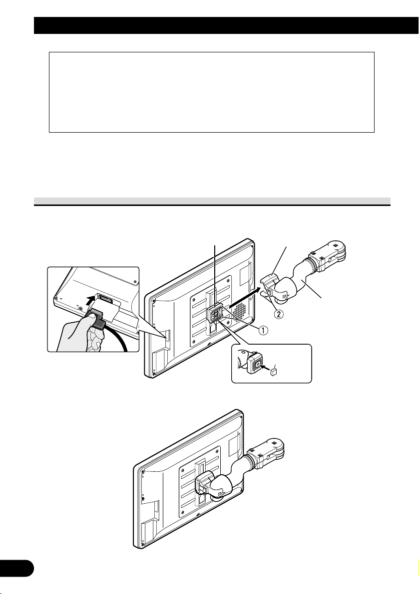
To fit the display
1. Fit part 1 of the bracket into the grooves 2 of the base.
2. Slide the display until it clicks into place.
Precaution:
• To prevent failure, be sure to turn the ignition switch or system power OFF before fitting or
removing the display. Also take care not to grip the screen or buttons too firmly or to drop the
display.
• Do not let any water get on the terminals on the display or on the cable and do not allow the terminals to be shorted by a metal object or the like. This can cause system breakdown.
• Be careful not to touch terminals on the display or on the cable. Doing so may cause connection
failures. If any terminals are stained, wipe them with a clean dry cloth.
Base
Bracket
Mounting arm
(sold separately)
Attach the
Bracket stopper
on the bracket
before installing
on the display.
Bracket
stopper
Connect the cable to the
display.
Page 5
4
ENGLISH
ESPAÑOL
DEUTSCH
FRANÇAIS
ITALIANO
NEDERLANDS
кмллдав
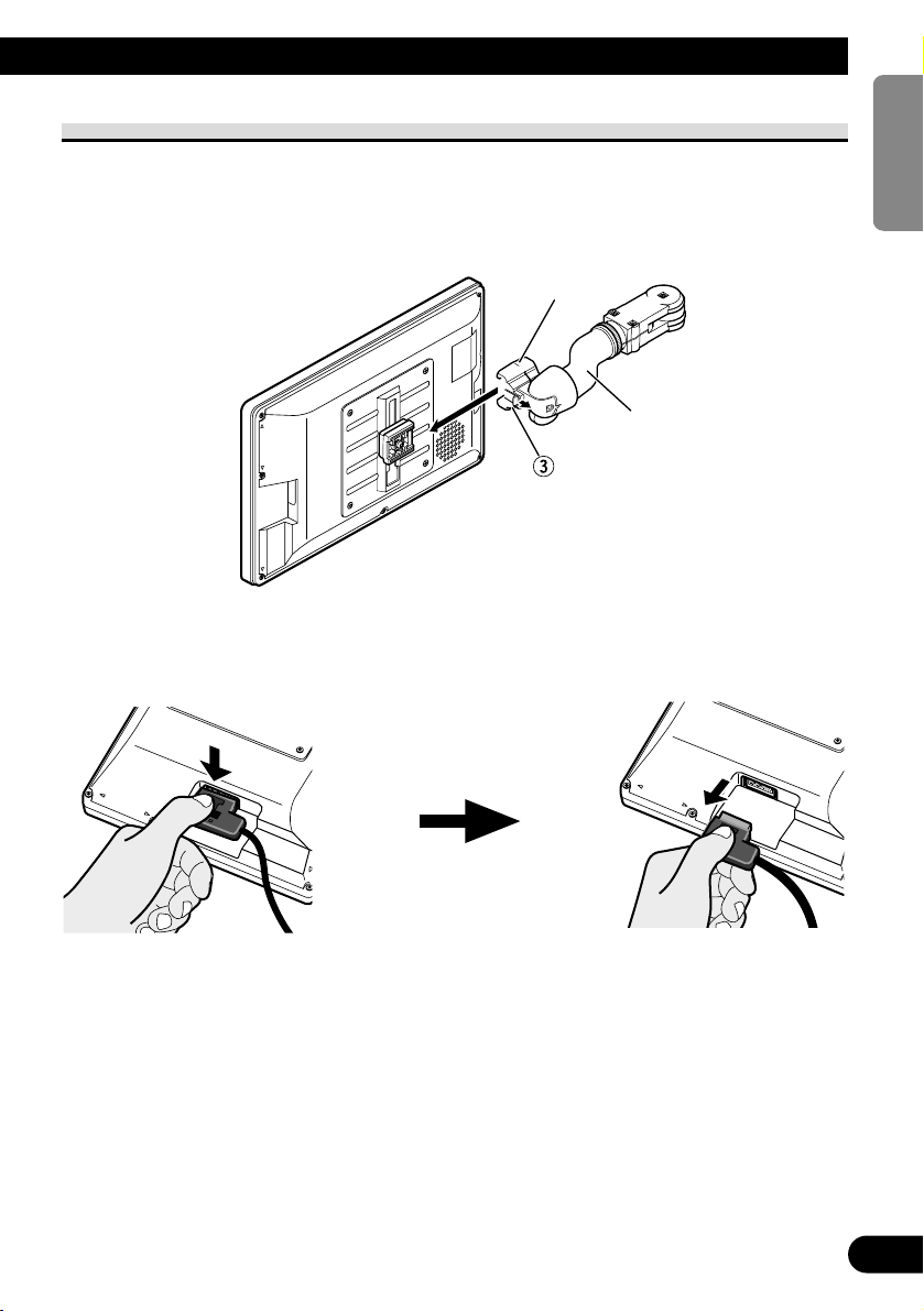
To remove the display
• Pull and hold the lock release lever 3, then slide the display and detach from
the base.
• To prevent theft of the display, remove the display when leaving the vehicle.
Base
Mounting arm
(sold separately)
Press the lock release button. Keep holding the button and
unplug the connector.
Page 6

5
About This Product
• Do not place the display in a position where it will impede the driver’s visibility or
affect the operation of your vehicle’s airbags or headrests.
• This product is designed solely for use from the rear seats. Never install the display in a
location that enables the driver to watch the picture while driving.
CAUTION
Do not allow this product to come into contact with liquids. Electrical shock
could result. Also, this product damage, smoke, and overheat could result
from contact with liquids.
Product Registration
Visit us at the following site:
• Register your product. We will keep the details of your purchase on file to help you refer
to this information in the event of an insurance claim such as loss or theft.
• We offer the latest information about Pioneer Corporation on our website.
Precaution
• Always keep the volume low enough for outside sounds to be audible.
• Protect the product from moisture.
In Case of Trouble
Should this product fail to operate properly, contact your dealer or the nearest authorized
Pioneer service facility.
IMPORTANT INFORMATION
Private households in the 25 member states of the EU, in Switzerland and Norway may return
their used electronic products free of charge to designated collection facilities or to a retailer
(if you purchase a similar new one).
For countries not mentioned above, please contact your local authorities for the correct
method of disposal.
By doing so you will ensure that your disposed product undergoes the necessary treatment,
recovery and recycling and thus prevent potential negative effects on the environment and
human health.
If you want to dispose this product, do not mix it with general household waste.
There is a separate collection system for used electronic products in accordance with
legislation that requires proper treatment, recovery and recycling.
Page 7
To Avoid Battery Exhaustion
Always run the vehicle engine while using this unit. Using this unit without running the
engine can result in battery drainage.
To Protect the LCD Screen of the Display
• Do not allow direct sunlight to fall on the Display when this unit is not being used.
Extended exposure to direct sunlight can result in LCD screen malfunction due to the
resulting high temperatures.
• When using a portable phone, keep the antenna of the portable phone away from the
Display to prevent disruption of the video by the appearance of spots, colored stripes,
etc.
When Viewing is Difficult, use [BRIGHT] and [DIMMER] to Adjust
Due to its construction, the view angle of the LCD screen is limited. The viewing angle
(vertical and horizontal) can be increased, however, by using [BRIGHT] to adjust the
black density of the video. When using for the first time, adjust the black density in accordance with the viewing angle (vertical and horizontal) to adjust for clear viewing.
[DIMMER] can also be used to adjust the brightness of the LCD screen itself to suit your
personal preference.
About the Video and Audio Outputs of this Unit
When you connect a separate piece of AV equipment such as another display to COMPONENT OUT or VCR OUT (the RCA video and audio output) jacks of the hide-away unit,
you can select the source for output with the SOURCE/POWER button.
• The video and audio source of the COMPONENT/RCA outputs of this unit cannot be
selected independently.
• VOL–, VOL+ buttons will have no effect even if operated.
CAUTION
Never position the display in a place where the driver can view the picture
while the vehicle is moving.
6
Before Using This Product
ENGLISH
ESPAÑOL
DEUTSCH
FRANÇAIS
ITALIANO
NEDERLANDS
кмллдав
Page 8
7
Before Using This Product
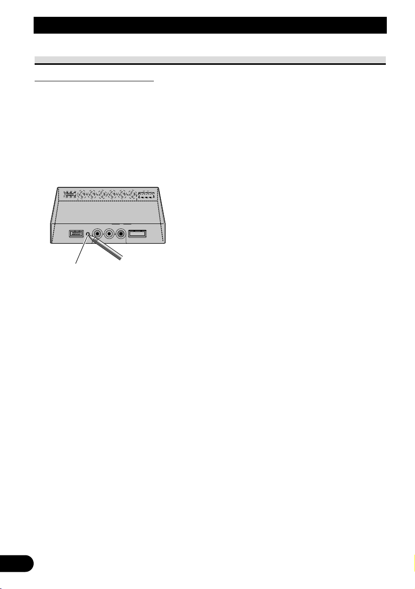
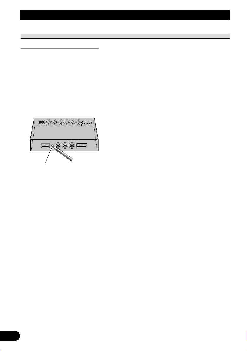
Resetting the System
Resetting the Microprocessor
Pressing the RESET button lets you reset the microprocessor to its initial settings, erase all
memorized settings, and return the setup function to their initial (factory) settings.
Reset the microprocessor in the following cases:
When using this product for the first time after installation.
When the product fails to operate properly.
When strange (incorrect) messages appear on the display.
• To reset the microprocessor, press the RESET button on the hide-away unit
with a pen tip or other pointed instrument.
RESET button
Page 9
ENGLISH
ESPAÑOL
DEUTSCH
FRANÇAIS
ITALIANO
NEDERLANDS
кмллдав
8
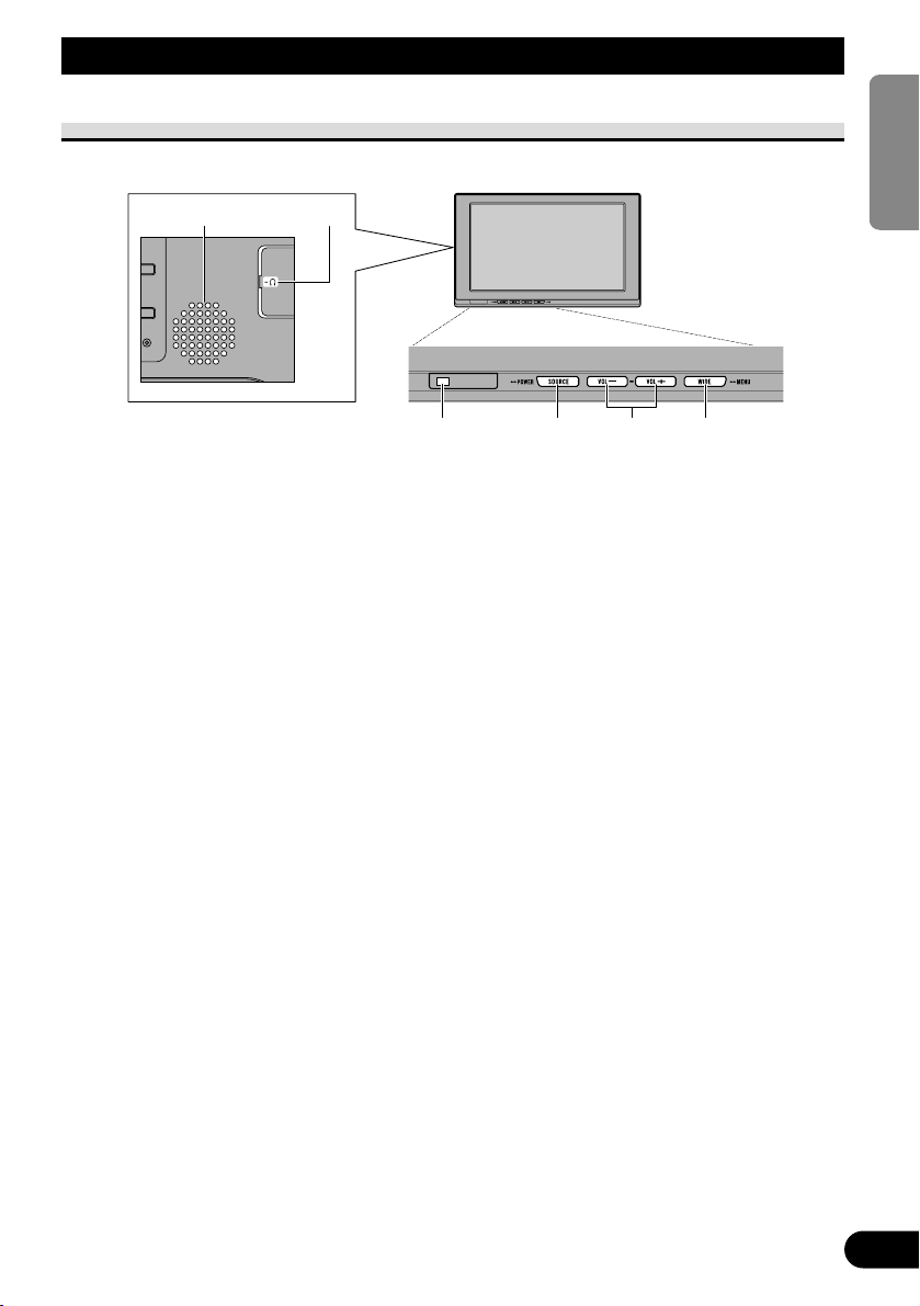
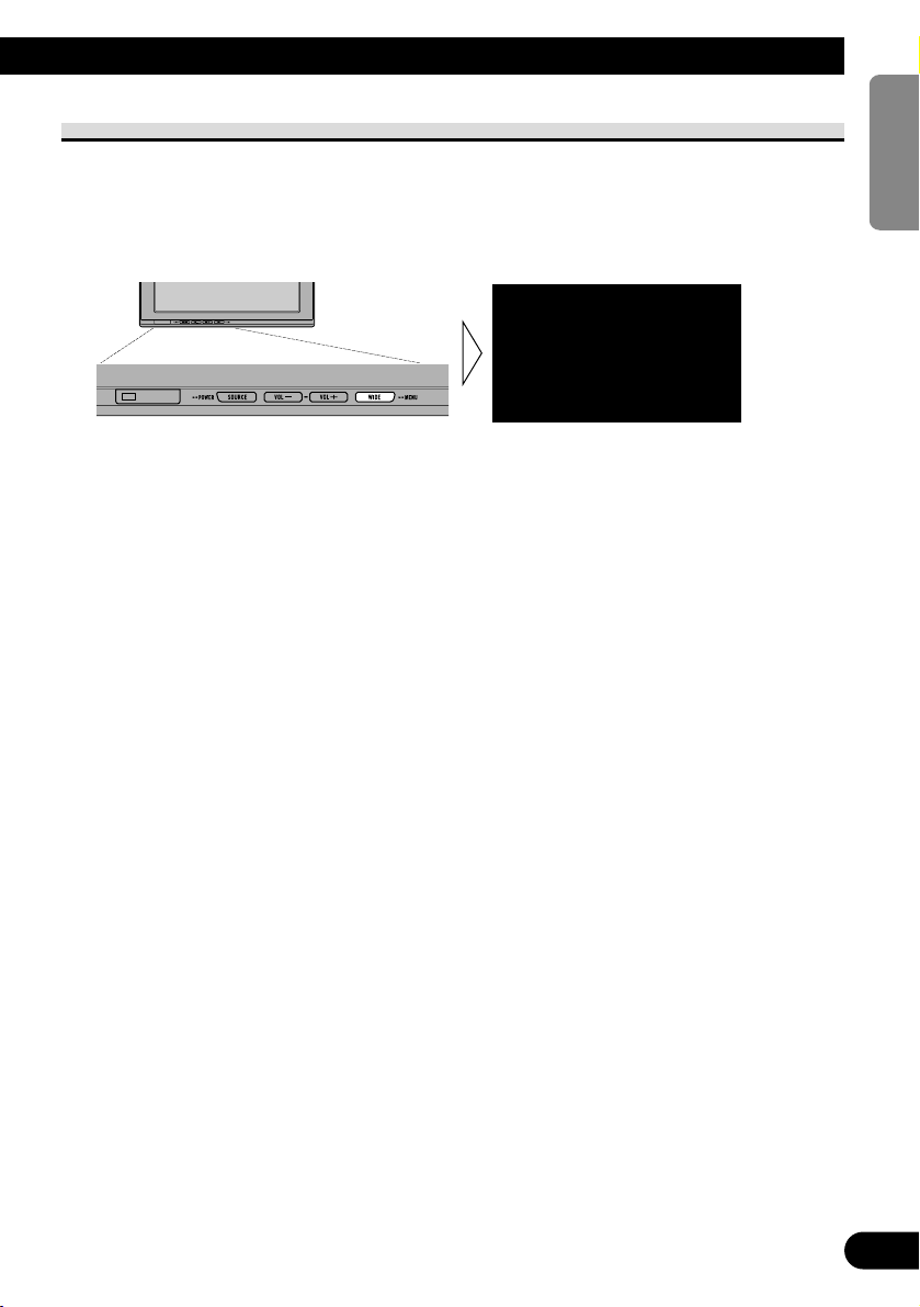
Key Finder
Component Parts and Features
7 Display Unit
1 Built-in speaker
Outputs sound from audio equipment
connected to this product.
2 Headphone jack
Connects a headphone with a 3.5 mm
stereo mini-plug.
3 Ambient light sensor
Senses ambient light. With this system,
the brightness of the LCD screen automatically adjusts to ambient light.
4 SOURCE/POWER button
Switches between sources.
Switches power ON/OFF.
5 VOL–, VOL+ buttons
Adjust the volume of the built-in
speaker 1, or adjust headphone vol-
ume when connected.
Change the settings when the setup
function is displayed.
Note:
• Never set the volume so high that you
cannot hear outside traffic and emergency
vehicles.
6 WIDE/MENU button
Changes the method of enlarging 4:3
video to 16:9 video. Press and hold this
button displays the setup menu or picture adjust menu. Once the setup menu
or picture adjust menu is displayed, its
function is switched each time the button is pressed.
1 2
3 4 5 6
Page 10
WARNING
Never install this product in a place where it is visible to the vehicle’s driver.
Failing to do so could result in distracting images being potentially visible to
the driver while the vehicle is in motion.
Use of this product is subject to any government laws regarding placement
or use.
PIONEER does not accept any liability for any problems, damage or loss
incurred as a result of the product being used with an incorrect setting or in
violation of any government laws.
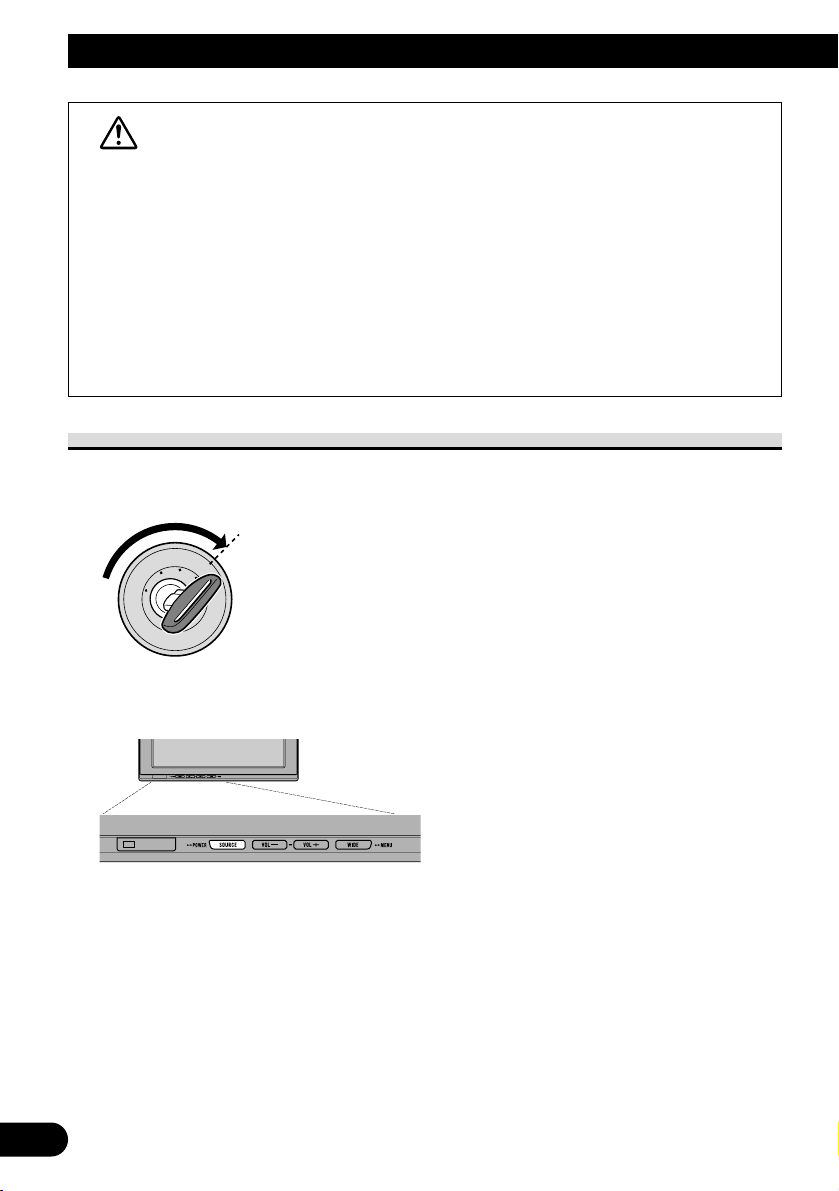
Turn On Power
Remember to start the vehicle engine before turning on the power to preserve battery life.
1. Start the vehicle engine.
2. Turn on the system.
Press the SOURCE/POWER button.
To turn off the system, press and hold the SOURCE/POWER button.
9
Basic Operation
O
N
C
S
C
T
A
A
K
C
O
L
R
T
Page 11
ENGLISH
ESPAÑOL
DEUTSCH
FRANÇAIS
ITALIANO
NEDERLANDS
кмллдав
10
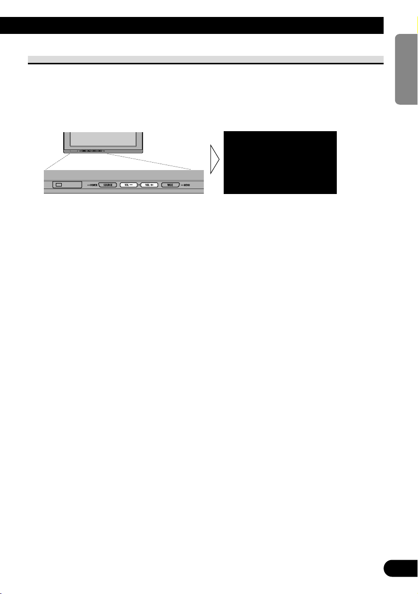
Volume Adjustment
Adjust the volume of audio output from the built-in speaker.
1. Adjust the speaker volume.
Press the VOL– or VOL+ button.
VOL+: Turn up
VOL–: Turn down
The volume of the built-in speaker can be adjusted in a range of 0 to 30.
Note:
• VOL−and VOL+ buttons adjust headphone volume when connected.
• Audio from the built-in speaker is turned off when headphones are connected.
VOL12
Page 12
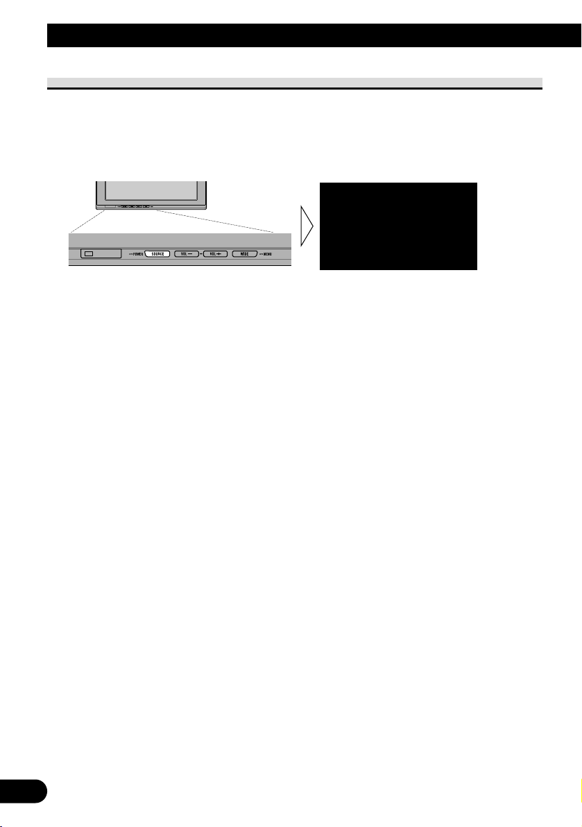
11
Selecting a Source
Switches video and audio source inputs from the AV equipment connected to VCR1 IN,
VCR2 IN, or COMPONENT IN.
1. Select a source.
Press the SOURCE/POWER button. Each press of the button selects the desired source in
the following sequence:
[VCR1 (COMPONENT)] or [VCR1] = [VCR2] = Exit to [VCR1 (COMPONENT)] or
[VCR1]
Note:
• This product has two source inputs; VCR1 IN and VCR2 IN.
VCR1 IN has a component video input [VCR1(COMPONENT)] as well as an RCA video input
[VCR1].
• [VCR1 (COMPONENT)] is a component video from the AV equipment connected to the VCR1 IN
COMPONENT terminal. 26pin component cable (CD-CP300), which is sold separately is required.
(Refer to page 28.)
• VCR1 COMPONENT input is given priority over VCR1 RCA input when both input are connected
at the same time.
• A video input terminal which is not connected cannot be selected even if the SOURCE/POWER
button is pressed.
• [VCR1] is selected when no connection is made for both VCR1 and VCR2 input.
VCR1[COMPONENT
]
Basic Operation
Page 13
Changing the Wide Screen Mode
You can change the way in which normal video (aspect ratio 4:3) enlarges to wide video
(16:9). Select wide modes to suit the kind of video you are viewing.
1. Display a source to view. (Refer to page 11.)
2. Select a wide mode.
Each press of the WIDE/MENU button selects the wide mode in the following order:
[AUTO] or [FULL] = [JUST] = [CINEMA] = [ZOOM] = [NORMAL] = Exit to
[AUTO] or [FULL]
Note:
• Settings are stored for each source (COMPONENT, VCR1, or VCR2).
• When video is viewed in a wide mode that does not match its original aspect ratio, it may appear
differently.
• [AUTO] is selectable only if the AV equipment is connected to the COMPONENT IN video input
terminal. When wide mode information is included in the video signal, the wide mode adjusts automatically according to the information.
• Remember that using the wide mode feature of this system for commercial or public viewing purposes may constitute an infringement on the author’s rights protected by the Copyright Law.
FULL
12
ENGLISH
ESPAÑOL
DEUTSCH
FRANÇAIS
ITALIANO
NEDERLANDS
кмллдав
Page 14
13
Basic Operation
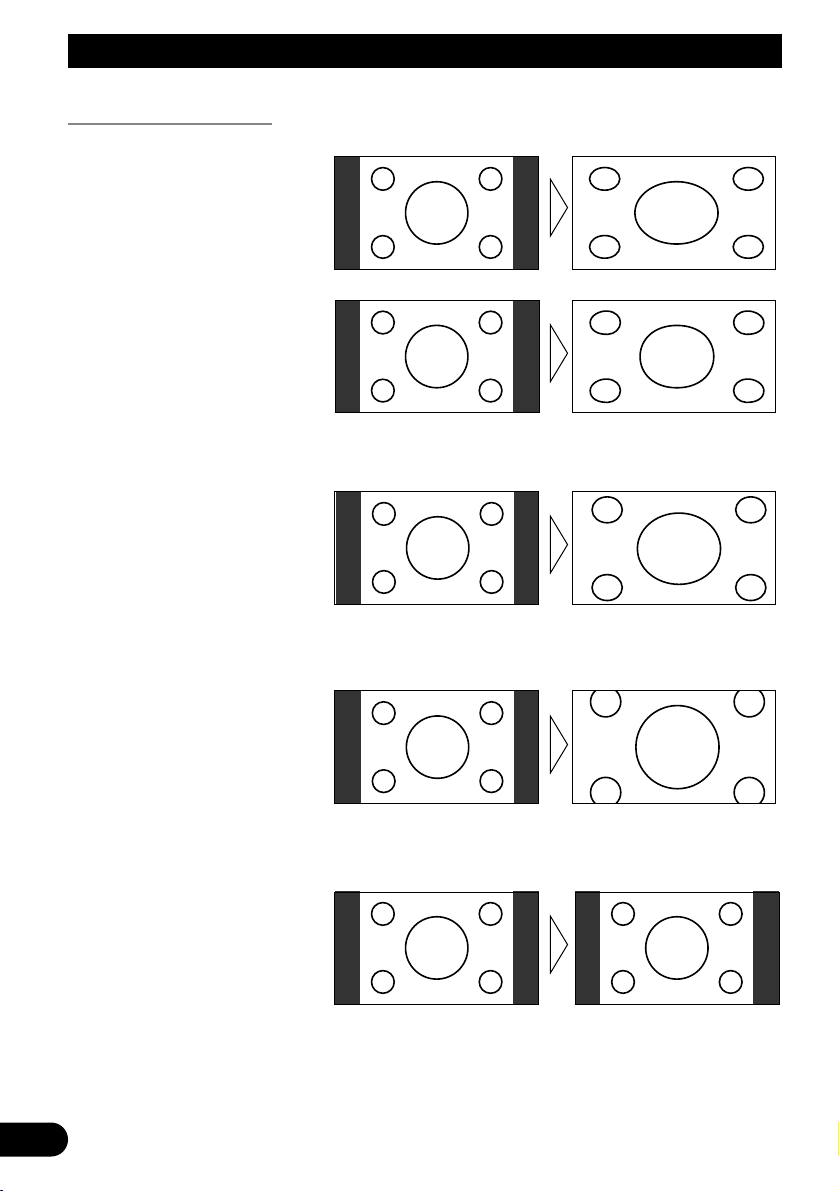
Wide Modes Available
Note:
• Video will appear roughened when viewed in CINEMA or ZOOM mode.
NORMAL
Video with an aspect ratio of 4:3
appears without enlarging. Enjoy
viewing TV in the same video as it
is broadcast.
ZOOM
Video with an aspect ratio of 4:3
enlarges with the same aspect ratio
in both vertical and horizontal
directions. This wide mode is suited for horizontally long video,
such as movies, in which titles
overlap the video.
CINEMA
Video enlarges vertically with a
aspect ratio falling between FULL
and ZOOM. This wide mode is
suited for horizontally long video,
such as movies, in which titles are
displayed in black areas outside
the video.
JUST
Video appears more extended horizontally as it gets closer to both
edges of the screen. Because video
appears in about the same size as
regular video around the middle of
the screen, enjoy viewing it without feeling out of place.
FULL
Video with an aspect ratio of 4:3
enlarges only horizontally. Enjoy
viewing video widened without
missing parts.
Page 15
ENGLISH
ESPAÑOL
DEUTSCH
FRANÇAIS
ITALIANO
NEDERLANDS
кмллдав
14
Adjusting the Screen
This system offers a number of functionality setup and adjustment features to make it easier to use. Customize the settings to suit your taste and environment.
Picture Adjustment (BRIGHT/CONTRAST/COLOR/HUE)
You can change the brightness [BRIGHT] of black, contrast [CONTRAST], darkness of
colors [COLOR], and the hue [HUE] of video to taste. Separate settings are stored for
video from VCR1 (COMPONENT), VCR1, and from VCR2.
1. Display a source to view. (Refer to page 11.)
2. Display a menu screen.
Press and hold the WIDE/MENU button for 2 seconds or longer.
The [PICTURE ADJUST] screen is displayed.
3. Select an item to adjust.
Press the WIDE/MENU button. Selected item turns to blue.
Each press of the WIDE/MENU button selects the item in the following order:
[BRIGHT] = [CONTRAST] = [COLOR] = [HUE] = [DIMMER] = Exit to
[BRIGHT]
4. Adjust the item.
Press the VOL– or VOL+ button.
VOL+: Increase values.
VOL–: Decrease values.
Each item can be adjusted within the range of –24 to +24.
The external light sensor of the display senses
the ambient brightness and displays a mark indicating the current brightness.
(blue): when dark (nighttime)
(red) : when bright (daytime)
COLOR
BRIGHTBRIGHT
CONTRAST
HUE
DIMMER
CONTRAST
HUE
DIMMER
PICTURE ADJUST
0
0
0
0
0
0
5
PICTURE ADJUST
BRIGHT
CONTRAST
COLOR
HUE
DIMMER
CONTRAST
COLOR
HUE
DIMMER
0
000
0
00
Page 16

15
Adjusting the Screen
5. Complete the setting.
Press and hold the WIDE/MENU button for 2 seconds or longer to close the menu and
complete the setting.
Adjustment item – side + side
BRIGHT Brightness of black Makes black appear darker. Makes black appear lighter.
CONTRAST Contrast Narrows the gap between Widens the gap between
black and white (darken). black and white (brighten).
COLOR Color darkness Makes colors appear lighter. Makes colors appear darker.
HUE Hue Increases red. Increases green.
Note:
• The settings of [BRIGHT] and [CONTRAST] are stored separately for light ambient (daytime) and
dark ambient (nighttime).
• A red mark ( ) or blue mark ( ) is displayed to the right of [BRIGHT] and [CONTRAST] on
the screen, respectively, as the ambient light sensor determines brightness or darkness.
• If you do nothing for about 30 seconds after displaying the picture adjust menu, the menu screen
will disappear.
• [HUE] can be adjusted for NTSC video only.
Page 17
ENGLISH
ESPAÑOL
DEUTSCH
FRANÇAIS
ITALIANO
NEDERLANDS
кмллдав
16
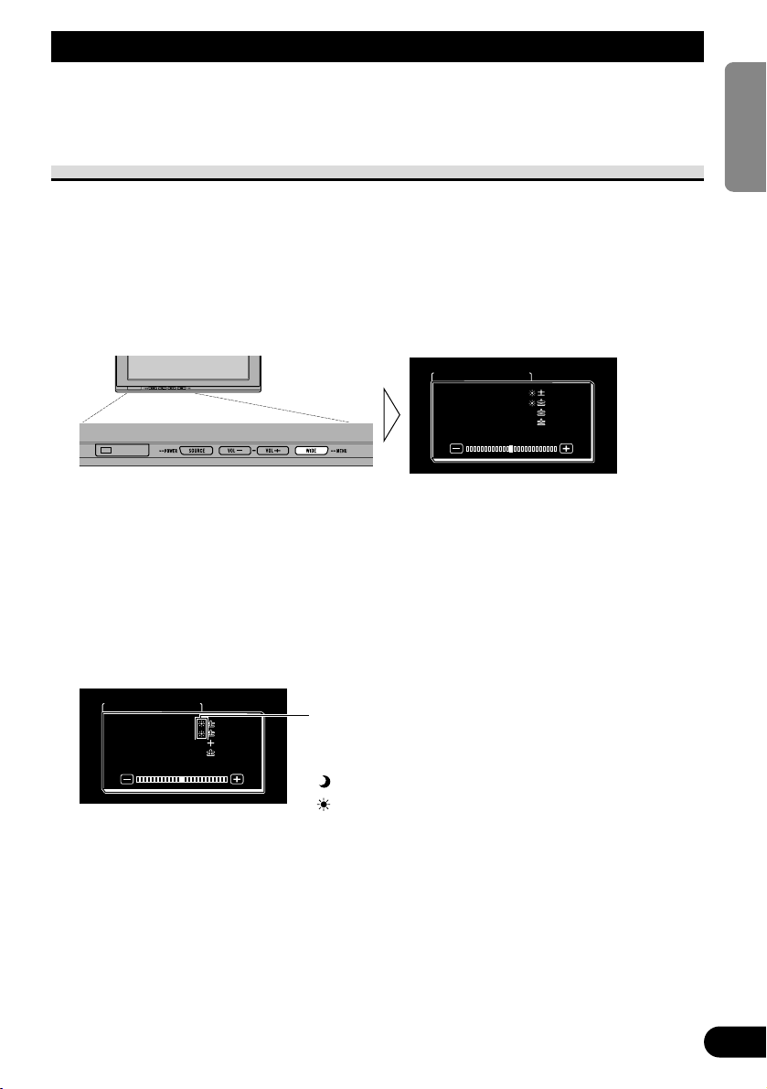
Picture Adjustment (DIMMER)
Viewing can become difficult after extended video viewing if the screen is too bright at
night or when the ambient brightness becomes dark. This device automatically adjusts the
brightness of the LCD screen in accordance with the ambient brightness (3-point intelligent dimmer). The automatically set brightness can also be adjusted by setting to the
desired brightness.
1. Display a menu screen.
Follow step 1 and step 2 in the “Picture Adjustment (BRIGHT/CONTRAST/COLOR/HUE)”.
(Refer to page 14.)
2. Select [DIMMER].
Press the WIDE/MENU button repeatedly until [DIMMER] is selected.
Note:
• The external light level used as the standard for adjusting [DIMMER] is indicated by the mark
shown in step 2 and its position. The marks indicating the current ambient brightness used for
adjusting [BRIGHT] and [CONTRAST] may differ slightly.
Blue: dark (night time)
The external light sensor of the monitor screen
senses the ambient brightness and changes the
color, shape and position of the mark according
to the current brightness (external light level).
DIMMER
PICTURE ADJUST
CONTRAST
COLOR
HUE
CONTRAST
COLOR
HUE
BRIGHTBRIGHT
0
0
5
0
0
0
5
0
Yellow: bright (day time)
Red: intermediate brightness (evening)
Page 18

17
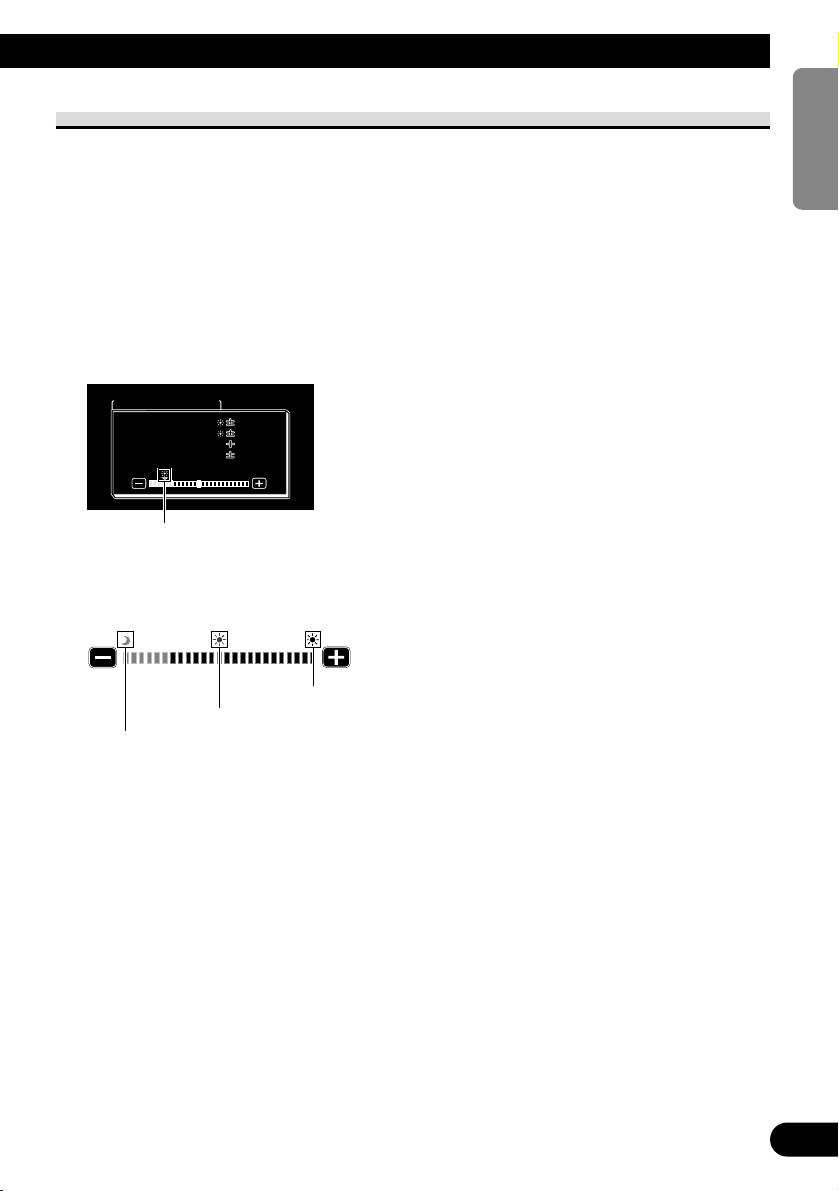
3. Adjust brightness.
Press the VOL– or VOL+ button.
VOL+: Brighten.
VOL–: Darken.
The more the yellow mark extends to the right, the brighter the screen appears.
• The current external light level is set and the screen brightness is adjusted.
• The external light level can be adjusted to Dark, Intermediate or Bright and the setting
saved.
4. Complete the setting.
Press and hold the WIDE/MENU button for 2 seconds or longer to close the menu and
complete the setting.
Note:
• If you do nothing for about 30 seconds after displaying the picture adjust menu, the menu screen
will disappear.
This level indicates the brightness of the screen being adjusted.
The farther yellow moves to the right, the brighter the screen.
With this screen, the brightness setting
of the screen can be adjusted when it is
dark ( ).
DIMMER
PICTURE ADJUST
CONTRASTCONTRAST
COLORCOLOR
HUEHUE
CONTRAST
COLOR
HUE
BRIGHTBRIGHTBRIGHT
0
0
5
0
0
0
5
0
Adjusting the Screen
Page 19
ENGLISH
ESPAÑOL
DEUTSCH
FRANÇAIS
ITALIANO
NEDERLANDS
кмллдав
18
Settings
Input Setting (VCR1/VCR2)
Video formats such as NTSC, PAL, and SECAM can be selected depending on the format
of the AV equipment connected to this unit.
1. Turn off the system.
Press and hold the SOURCE/POWER button.
2. Display a setup menu.
Press and hold the WIDE/MENU button for 2 seconds or longer. The [SETUP MENU]
screen is displayed. [VCR1] has already been selected.
3. Select between [VCR1] and [VCR2].
Press the WIDE/MENU button. Selected item turns to blue.
4. Select video format.
Press the VOL+ button. The video system switches.
Each press of the VOL+ button selects the item in the following order:
[AUTO] = [NTSC] = [PAL] = [SECAM] = Exit to [AUTO]
Note:
• Pressing the VOL– button selects the item in the reverse order of the VOL+ button.
5. Complete the setting.
Press and hold the WIDE/MENU button for 2 seconds or longer to close the menu and
complete the setting.
Note:
• If [AUTO] is selected, NTSC, PAL, and SECAM are automatically identified and displayed.
• Broadcast reception may be inferior when [AUTO] is selected.
• If you do nothing for about 30 seconds after displaying the setup menu, the menu screen will disappear.
SETUP MENU
VCR1
VCR2 AUTO
NORMAL
VCR2
PAL
AUTO
NORMALPOWER . CPOWER . C
SETUP MENU
VCR1
VCR2 AUTO
NORMAL
VCR2
AUTO
AUTO
NORMALPOWER . CPOWER . C
Page 20

19
Power Control Function
When connecting with a head unit which has Power Control function, such as the AVHP7800DVD, you can turn the AVD-W1100V ON or OFF through the head unit.
1. Display a setup menu.
Follow step 1 and step 2 in the “Input Setting (VCR1/VCR2)”. (Refer to page 18.)
2. Select [POWER.C].
Press the WIDE/MENU button. The selected item turns to blue.
3. Select Power Control function.
VOL–: [NORMAL]
You can turn this unit ON/OFF by pressing the SOURCE/POWER button.
VOL+: [FRONT]
You CANNOT turn this unit ON/OFF by pressing the SOURCE/POWER button.
ON/OFF control is provided by a head unit with Power Control function connected
by the CD-CP300 26pin component cable. (sold separately.)
e.g., when connected with AVH-P7800DVD.
Pressing REAR ON button on AVH-P7800DVD turns this unit ON. Press and hold
the button on the AVH-P7800DVD to turn the unit OFF.
4. Complete the setting.
Press and hold the WIDE/MENU button for 2 seconds or longer to close the menu and
complete the setting.
Note:
• If you do nothing for about 30 seconds after displaying the setup menu, the menu screen will disappear.
SETUP MENU
VCR1VCR1 AUTAUTOVCR1
VCR2VCR2
POWER . C
AUTAUTO
NORMAL
VCR2
AUTO
AUTO
Settings
Page 21

ENGLISH
ESPAÑOL
DEUTSCH
FRANÇAIS
ITALIANO
NEDERLANDS
кмллдав
20
Using the Display Correctly
CAUTION
• If moisture or foreign matter should get inside the unit, turn OFF the power
immediately and consult your dealer or the nearest authorized PIONEER
service facility. Using the unit in this condition may result in a fire, electric
shock or other failure.
• If you notice smoke, a strange noise or smell, or any other abnormal signs
from the display, turn OFF the power immediately and consult your dealer
or the nearest authorized PIONEER service facility. Using the unit in this
condition may result in failure of the system.
• Do not remove the rear cover of the display, as there are high-voltage components inside which may cause an electric shock. Be sure to consult your
dealer or the nearest authorized PIONEER service facility for internal
inspection, adjustments or repairs.
Handling the Display
• When the display is not being used, never leave it under the direct sunlight or in extreme
temperatures.
• The display should be used within the temperature ranges shown below.
Operating temperature range: –10 °C to +50 °C
Storage temperature range: –20 °C to +80 °C
At temperatures higher or lower than the operating temperature range, the display may
not operate normally.
• The LCD screen of this product is exposed to improve view ability in the vehicle. Do not
push the LCD screen strongly. This could break it.
• Do not touch the LCD screen. This could cause scratches or soiling.
Page 22

About the Liquid Crystal Display (LCD) Screen
• If the display is installed near the vent of an air conditioner, make sure that air from the
air conditioner is not blowing on it. Hot air may break the LCD screen, and cool air may
cause moisture to form inside the display resulting in possible damage. Also, if the display is cooled down by cool air, the screen may become dark, or the life span of the
small fluorescent tube used inside the display may be shortened.
• Small black dots or white dots (bright dots) may appear on the LCD screen. These are
due to the characteristics of the LCD screen and do not indicate a problem with the display.
• At low temperatures, the LCD screen may be dark for a while after the power is turned
ON.
• The LCD screen will be difficult to see if it is exposed to direct sunlight.
Keeping the Display in Good Condition
• When removing dust from the screen or cleaning the display, first turn the system power
OFF, then wipe with a soft dry cloth.
• When wiping the screen, take care not to scratch the surface. Do not use harsh or abrasive chemical cleaners.
• Do not use a wet cloth for cleaning. Do not use organic solvents, such as benzine, thinner.
About the Small Fluorescent Tube
• A small fluorescent tube is used inside the display to illuminate the LCD screen.
* The fluorescent tube is an expendable part and has a limited service life.
* The fluorescent tube should last for approximately 10 000 hours, depending on oper-
ating conditions. (Using the display at low temperatures reduces the service life of the
fluorescent tube.)
* When the fluorescent tube reaches the end of its useful life, the screen will be dark
and the image will no longer be projected. If this happens, consult your dealer or the
nearest authorized PIONEER service facility.
21
Using the Display Correctly
Page 23

22
Connecting the System
ENGLISH
ESPAÑOL
DEUTSCH
FRANÇAIS
ITALIANO
NEDERLANDS
кмллдав
CAUTION
• PIONEER does not recommend that you install or service your display yourself. Installing or servicing the product may expose you to risk of electric
shock or other hazards. Refer all installation and servicing of your display to
authorized Pioneer service personnel.
• Secure all wiring with cable clamps or electrical tape. Do not allow any bare
wiring to remain exposed.
• Do not drill a hole into the engine compartment to connect the yellow lead of
the unit to the vehicle battery. Engine vibration may eventually cause the
insulation to fail at the point where the wire passes from the passenger compartment into the engine compartment. Take extra care in securing the wire
at this point.
• It is extremely dangerous to allow the display lead to become wound around
the steering column or gearshift. Be sure to install the display in such a way
that it will not obstruct driving.
• Make sure that wires will not interfere with moving parts of the vehicle, such
as the gearshift, parking brake or seat sliding mechanism.
• Do not shorten any leads. If you do, the protection circuit may fail to work
properly.
Page 24
23
Connecting the System
Note:
• This unit is for vehicles with a 12-volt battery and
negative grounding. Before installing it in a recreational vehicle, truck, or bus, check the battery
voltage.
• To avoid short circuit in the electrical system, be
sure to disconnect the ≠ battery cable before
beginning installation.
• Refer to the owner’s manual for details on con-
necting other units, then make connections correctly.
• Secure the wiring with cable clamps or adhesive
tape. To protect the wiring, wrap adhesive tape
around them where they lie against metal parts.
• Route and secure all wiring so it cannot touch any
moving parts, such as the gear shift, handbrake
and seat rails. Do not route wiring in places that
get hot, such as near the heater outlet. If the insulation of the wiring melts or gets torn, there is a
danger of the wiring short-circuiting to the vehicle body.
• Don’t pass the yellow lead through a hole into the
engine compartment to connect to the battery.
This will damage the lead insulation and cause a
very dangerous short circuit.
• Never feed power to other equipment by cutting
the insulation of the power supply lead of the unit
and tapping into the lead. The current capacity of
the lead will be exceeded, causing overheating.
• When replacing a fuse, be sure to use only fuses
of the rating prescribed on the fuse holder.
• If this unit is installed in a vehicle that does not
have an ACC (accessory) position on the ignition
switch, the red lead of the unit should be connected to a terminal coupled with ignition switch
ON/OFF operations. If this is not done, the vehicle battery may be drained when you are away
from the vehicle for several hours.
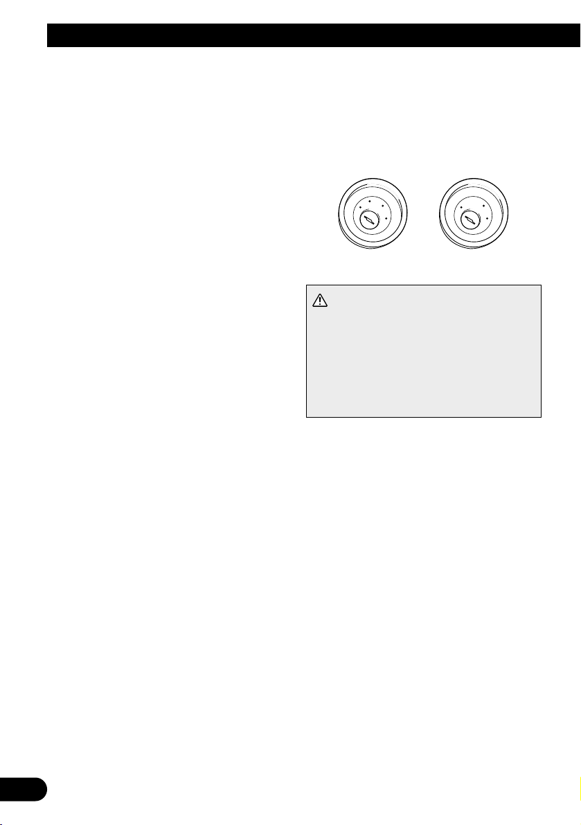
CAUTION
• Cords for this product and those for other
products may be different colors even if
they have the same function. When connecting this product to
another product, refer to the supplied
Installation manuals of both products and
connect cords that have the same function.
No ACC positionACC position
C
C
A
O
F
N
F
O
S
T
A
R
T
O
F
N
F
O
S
T
A
R
T
Page 25
ENGLISH
ESPAÑOL
DEUTSCH
FRANÇAIS
ITALIANO
NEDERLANDS
кмллдав
24
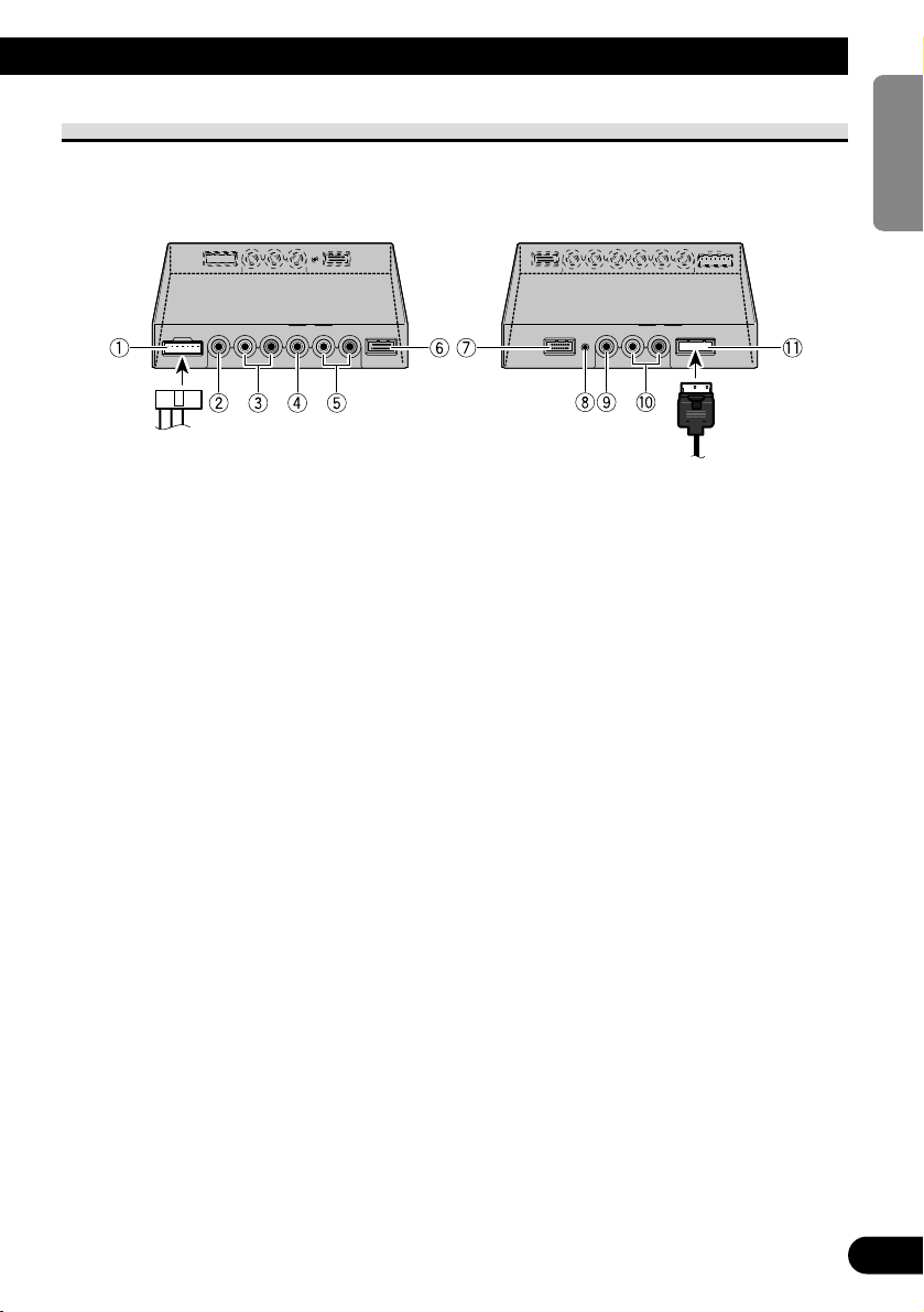
Names and Functions of Connection Terminals
7 Hide-away Unit
1 Power Supply
Receives the power cable supplied.
2 VCR2 RCA video input (yellow)
Receives video, as from a VCR, DVD or
other AV equipment.
3 VCR2 RCA audio input (white,
red)
Receives stereo audio, as from a VCR,
DVD or other AV equipment.
4 VCR1 RCA video input (yellow)
Receives video, as from a VCR, DVD or
other AV equipment.
5 VCR1 RCA audio input (white,
red)
Receives stereo audio, as from a VCR,
DVD or other AV equipment.
6 VCR1 COMPONENT Video
input (white)
Receives component video, as from a
VCR, DVD or other AV equipment which
has component video output.*
VCR1 COMPONENT Video input is given
priority when both VCR1 RCA video input
and VCR1 COMPONENT Video input are
connected.
* CD-CP300 26pin component cable (sold
separately) is required.
7 COMPONENT Video output
(blue)
Video and stereo audio from VCR1 input
are directed to this terminal. Connection to
another AVD-W1100V is possible with the
26pin component cable CD-CP300 (sold
separately).
8 Reset button
Resets the display microprocessor.
Press with the tip of a ballpoint pen or
similar object.
9 RCA video output (yellow)
Connects to other AV equipment. Video
selected with this display is directed to this
terminal.
0 RCA audio output (white, red)
Connects to other AV equipment. Audio
selected with this display is directed to
these terminals.
! Display output (pink)
Connects to the display unit.
Page 26
25
Connecting the System
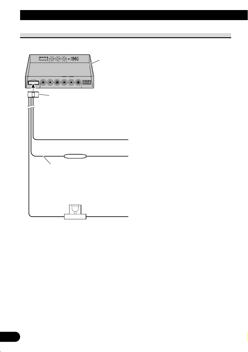
Connecting the Power Cable
Power cable
Fuse resistor
Hide-away Unit
Yellow
To the terminal always supplied with power regardless of ignition switch position.
Red
To the electric terminal controlled by the ignition
switch (12 V DC) ON/OFF.
Do not connect this lead to power source terminals
to which power is continuously supplied. If the lead
is connected to such terminals, the battery may be
drained.
Black (ground)
To vehicle (metal) body.
Fuse holder (4A)
Red/Gray
Page 27
ENGLISH
ESPAÑOL
DEUTSCH
FRANÇAIS
ITALIANO
NEDERLANDS
кмллдав
26
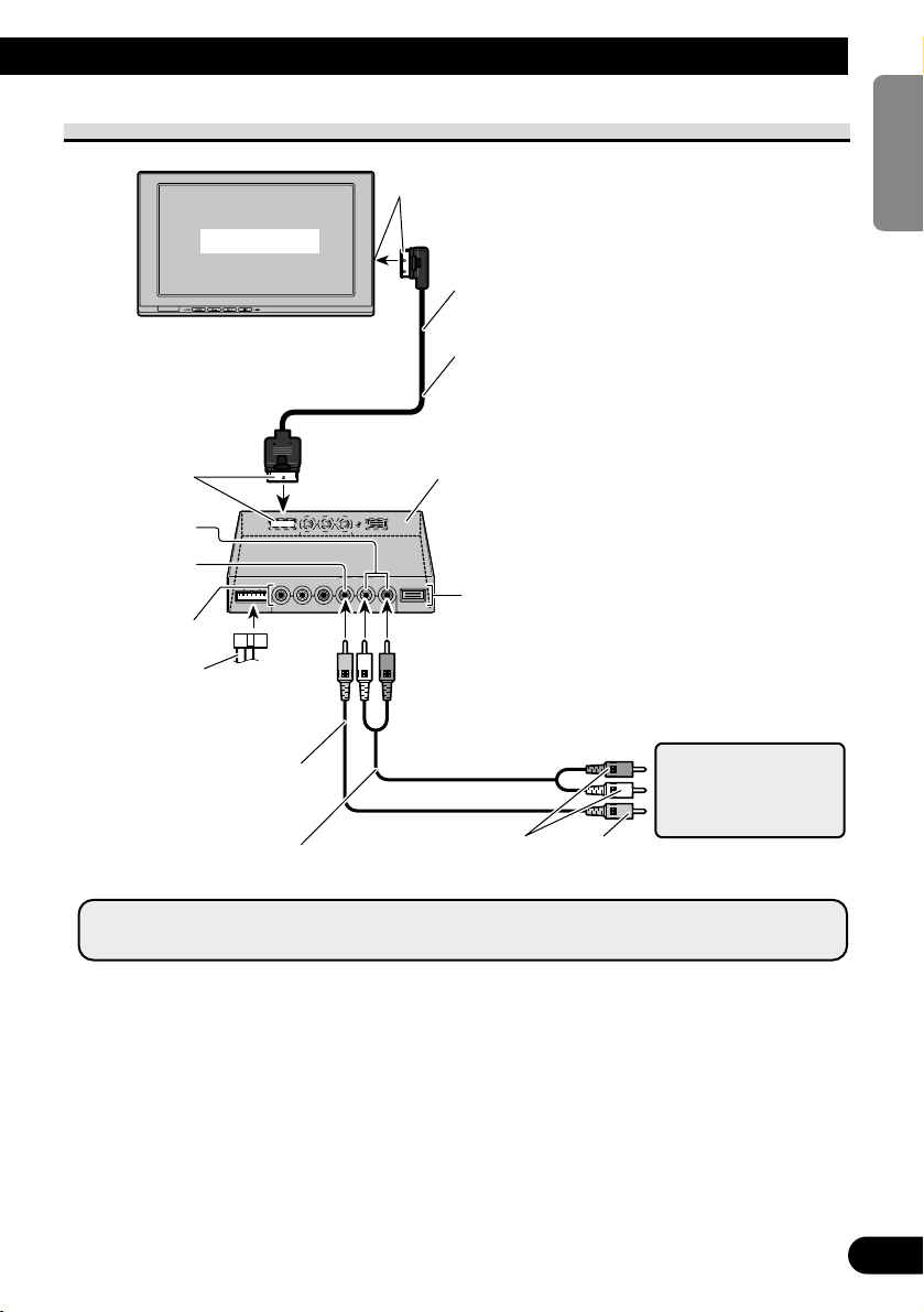
Connection Diagram (VIDEO input)
Display Unit
Note:
• Never install the display in a place where it is visible to the vehicle’s driver.
Pink
Pink
Commercially available portable video
component with RCA
output
To video output
To audio output
VCR1 INPUT
Hide-away Unit
4 m
Display cable
VCR1 RCA audio
input (white, red)
VCR1 RCA video
input (yellow)
RCA Video cable
(commercially available)
VCR2 INPUT
Power cable
(Refer to page 25.)
RCA Audio cable
(commercially available)
Page 28

27
Connecting the System
Connecting the Audio and Video Output
*: Use CD-CP301E 26pin component extension cable for extension (3m).
Hide-away Unit
COMPONENT
Video output
(Blue)
26pin component cable (CD-CP300)
(sold separately)*
To component video input (White)
of a second AVD-W1100V
Blue
3 m
RCA video output (Yellow)
RCA audio output (White, Red)
RCA Audio cable (commercially available)
RCA Video cable (commercially available)
To audio input
To video input
Second display, video
deck, etc.
You can connect a second AVD-W1100V with a 26pin
component cable CD-CP300 (sold separately).
Note:
• The signal from COMPONENT video and RCA audio/video is not output when the power of this
product is turned off.
Page 29
ENGLISH
ESPAÑOL
DEUTSCH
FRANÇAIS
ITALIANO
NEDERLANDS
кмллдав
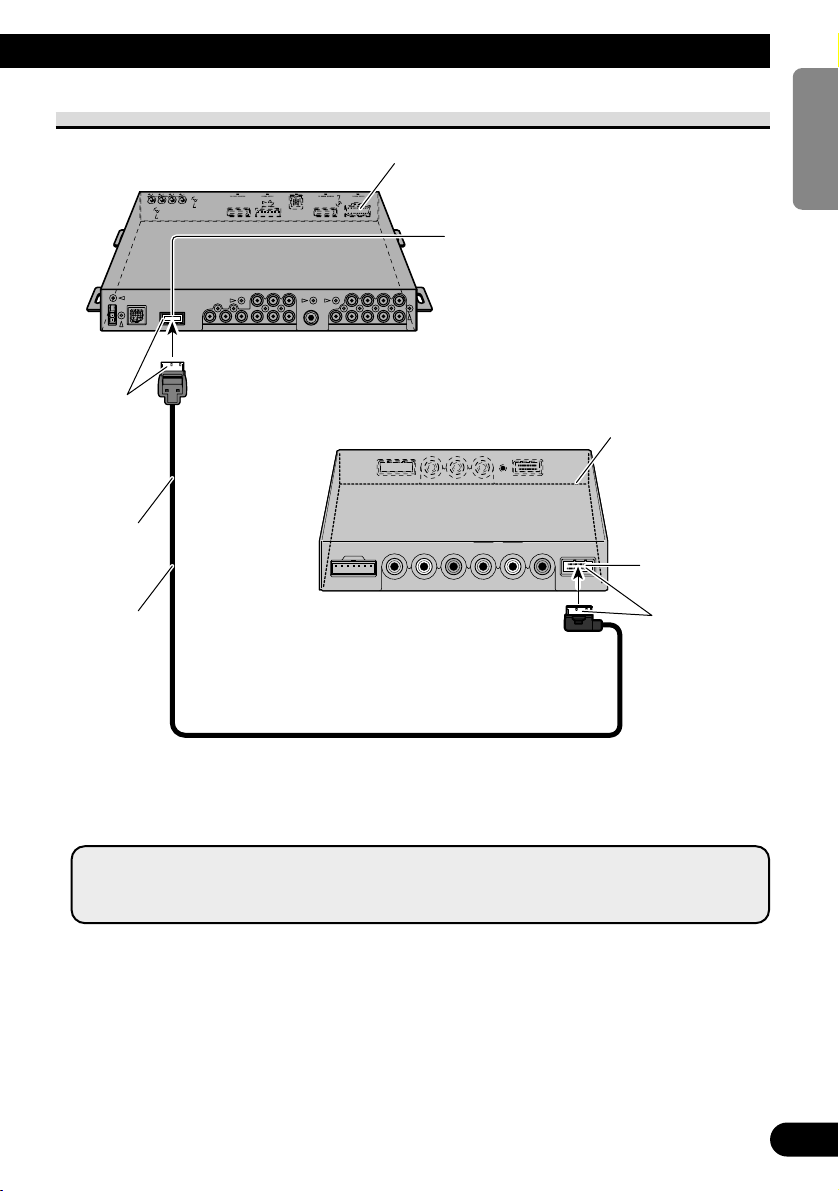
28
Connecting with Pioneer Head Unit with Component Cable
*: • Use CD-CP300 26pin component cable for Pioneer products.
• Use CD-CP301E 26pin component extension cable for extension (3m).
Blue
3 m
Component cable
(sold separately)*
Hide-away Unit (AVH-P7800DVD) (sold separately)
Hide-away Unit
White
VCR1 COMPONENT
video input (White)
COMPONENT Video output (Blue)
Note:
• When you watch DVD (built-in DVD player of AVH-P7800DVD) on both AVH-P7800DVD and
this product, audio is not output from the built-in speaker of this product.
Page 30

29
Installation
CAUTION
• For instructions on how to mount the display, consult your dealer.
• Do not install the display where it may (i) obstruct the driver’s vision, (ii)
impair the performance of any of the vehicle’s operating systems or safety
features, including airbags, or (iii) impair the driver’s ability to safely operate the vehicle.
• PIONEER does not recommend that you install or service your display
yourself. Installing or servicing the product may expose you to risk of electric shock or other hazards. Refer all installation and servicing of your display to authorized PIONEER service personnel.
• Install the display between the driver’s seat and front passenger seat so that
it will not be hit by the driver or passenger if the vehicle brakes sharply.
• Do not install the display in a position where the fully opened air bag will be
obstructed by it.
• Do not install the display in a place where it will impair the performance of
any of the vehicle’s operating systems, including airbags and headrests.
• Make sure there is nothing behind the panels when drilling holes in them. Be
careful not to damage fuel lines, brake lines or power cables.
• When using screws, do not allow them to come into contact with any electrical lead. Vibration may damage wires, leading to a short circuit or other
damage to the vehicle.
• It is extremely dangerous to allow the display lead to become wound around
the steering column or shift lever. Be sure to install the display in such a way
that it will not obstruct driving.
• Make sure that leads cannot get caught in a door or the sliding mechanism
of a seat, resulting in a short circuit.
Page 31

ENGLISH
ESPAÑOL
DEUTSCH
FRANÇAIS
ITALIANO
NEDERLANDS
кмллдав
30
• Never install this product in a place where it is visible to the vehicle’s driver.
Failing to do so could result in distracting images being potentially visible to
the driver while the vehicle is in motion.
Use of this product is subject to any government laws regarding placement
or use.
PIONEER does not accept any liability for any problems, damage or loss
incurred as a result of the product being used with an incorrect setting or in
violation of any government laws.
• To ensure proper installation, use the supplied parts in the manner specified.
If any parts other than the supplied ones are used, they may damage internal
parts of the unit or they may work loose and the unit may come off.
Before Installing and Fixing
• Make temporary connections first to check that the unit and system are working properly.
• Press the RESET button with the tip of a ball-point pen or similar object, when a con-
nection is completed.
Before Affixing the Adhesive Tape
• Make sure the surface is free of moisture, dust, grime, oil, etc. before affixing the tape.
Page 32

31
Installation
Installing the Hide-away Unit
Installation Precautions
• Never install in locations such as the following because of the danger of malfunction due to high
temperatures or humidity:
* Locations such as a dashboard or rear tray where there is exposure to direct sunlight.
* Near heater outlets.
* Near doors, etc., where there is danger of exposure to rain.
• When installing under the front seat, make sure there is no hindrance to sliding of the seat.
• Direct installation on the carpet is possible if the hard Velcro tape will adhere to the carpet. Do not
use the soft Velcro tape in this case.
Hide-away Unit Installation
Adhere the hard Velcro tape (supplied) to the bottom of the hide-away unit and adhere the
soft Velcro tape (supplied) to the installation location.
Hide-away Unit
Velcro tape (hard)
Velcro tape (soft)
Car mat
Page 33

32
Specifications
ENGLISH
ESPAÑOL
DEUTSCH
FRANÇAIS
ITALIANO
NEDERLANDS
кмллдав
General
Power source ...................................................................... 14.4 V DC (10.8 V to 15.1 V allowable)
Grounding system ................................................................ Negative type
Max. current consumption .................................................. 4.0 A
Storage temperature range .................................................. –20 °C to +80 °C
Display Unit
Dimensions .......................................................................... 297 (W) × 181 (H) × 42 (D) mm
Weight ................................................................................ 1.39 kg
Screen size/Aspect ratio ...................................................... 11.0 inch wide VGA/16:9
(effective display area: 245.6 × 139.5 mm)
Pixels .................................................................................... 1 152 000[800(Horizontal) × 480(Vertical) × 3(RGB)]
Display Method .................................................................. TFT active matrix driving
Color system ........................................................................ NTSC/PAL/SECAM compatible
Built-in Speaker.................................................................... ø 36 mm
Headphone output level........................................................ 8 mW+8 mW/16 Ω
Operating temperature range .............................................. –10 °C to +50 °C
Hide-away Unit
Dimensions .......................................................................... 178 (W) × 157 (H) × 30 (D) mm
Weight ................................................................................ 0.68 kg
Video input level ..................................................................NTSC, PAL, SECAM 1 Vp-p/75 Ω
Max. audio input level..........................................................1.5 V/22 kΩ
Video output level ................................................................NTSC, PAL, SECAM 1 Vp-p/75 Ω
Max. audio output level........................................................1.5 V/1 kΩ
Component input level ........................................................Y: 1 Vp-p/75 Ω
Cb, Cr: 0.7 Vp-p/75 Ω
Component output level ......................................................Y: 1 Vp-p/75 Ω
Cb, Cr: 0.7 Vp-p/75 Ω
Operating temperature range................................................ –10 °C to +60 °C
Note:
• The specifications and design are subject to change without prior notice. Products purchased may differ in
details from illustrations in this manual.
Page 34

1
Contenido
Contenido
.................................................... 1
PRECAUCIONES IMPORTANTES ............ 2
Lea todas estas instrucciones relacionadas
con su pantalla y guárdelas para
emplearlas como referencia en el futuro .... 2
Instalación y extracción
de la pantalla ...................................... 3
Para instalar la pantalla .................................... 3
Para extraer la pantalla ...................................... 4
INFORMACIÓN IMPORTANTE ................ 5
Sobre este producto .......................................... 5
Registro del producto ........................................ 5
Precaución ........................................................ 5
En caso de problema ........................................ 5
Antes de usar este producto .................... 6
Para evitar la descarga de la batería .................. 6
Para proteger la pantalla LCD de la pantalla .... 6
Cuando esté difícil de ver la imagen, utilice
[BRIGHT] (brillo) y [DIMMER] (reductor
de luz) para ajustar .................................... 6
Sobre las salidas de vídeo y audio de
esta unidad .................................................. 6
Reposición del sistema ...................................... 7
-
Reposición del microprocesador
Guía de los botones .................................. 8
Partes componentes y características ................ 8
Operación básica ...................................... 9
Encendido .......................................................... 9
Ajuste del volumen .......................................... 10
Selección de una fuente .................................. 11
Cambio del modo de la pantalla ancha ............ 12
-
Modos de pantalla ancha disponibles
Ajuste de la pantalla .............................. 14
Ajuste de la imagen
(BRIGHT/CONTRAST/COLOR/HUE)
.... 14
Ajuste de la imagen (DIMMER) .................... 16
Configuraciones........................................ 18
Configuración de entrada (VCR1/VCR2) ...... 18
Función de control de energía ........................ 19
Uso correcto de la pantalla .................. 20
Manejo de la pantalla ...................................... 20
Acerca de la pantalla de cristal líquido
(LCD) ...................................................... 21
Mantenimiento de la pantalla en buenas
condiciones .............................................. 21
Acerca del tubo fluorescente pequeño ............ 21
Conexión del sistema .............................. 22
Nombres y funciones de los terminales de
conexión .................................................. 24
Conexión del cable de alimentación ................ 25
Diagrama de conexión (entrada VIDEO) ........ 26
Conexión de la salida de audio y vídeo .......... 27
Conexión con una unidad principal Pioneer
con el cable de vídeo componente .......... 28
Instalación ................................................ 29
Antes de instalar y fijar la pantalla .................. 30
Antes de poner la cinta adhesiva .................... 30
Instalación de la unidad oculta-alejada .......... 31
-
Precauciones de instalación
-
Instalación de la unidad oculta-alejada
Especificaciones .................................... 32
Page 35

ENGLISH
ESPAÑOL
DEUTSCH
FRANÇAIS
ITALIANO
NEDERLANDS
кмллдав
2
PRECAUCIONES IMPORTANTES
Lea todas estas instrucciones relacionadas con su pantalla y guárdelas
para emplearlas como referencia en el futuro
1. Lea completa y cuidadosamente este manual antes de instalar su pantalla.
2. Guarde a mano este manual para utilizarlo como referencia en el futuro.
3. Ponga mucha atención a todas las advertencias de este manual y siga
cuidadosamente las instrucciones.
4. No permita que otras personas utilicen este sistema mientras no nayan entendido
las instrucciones de operación.
5. No instale la pantalla donde (i) pueda obstruir la visión del conductor, (ii) afecte
al rendimiento de cualquier sistema de funcionamiento o sistema de seguridad del
vehículo, incluyendo el air-bag, o (iii) afecte a la habilidad del conductor para
manejar con seguridad el vehículo.
6. Como con cualquier accesorio en el interior de su vehículo, la pantalla no debe
distraer su atención de la operación segura del vehículo. Si tiene dificultades para
operar el sistema, estacione con seguridad antes de hacer cualquier ajuste.
7. No intente instalar o revisar usted mismo su pantalla. La instalación o revisión de
la pantalla por personas sin formación ni experiencia en equipos electrónicos y
accesorios para automóviles puede ser peligroso y podría exponerle a una
descarga eléctrica o a otros peligros.
8. Recuerde ponerse siempre el cinturón de seguridad cuando maneje su automóvil.
En el caso de sufrir un accidente, sus lesiones pueden ser mucho más graves si no
tiene bien puesto su cinturón de seguridad.
9. Nunca instale este producto en un lugar donde quede visible al conductor del
vehículo. Dejar de hacer eso podría causar la distracción del conductor por imágenes potencialmente visibles mientras el vehículo esté en movimiento.
El uso de este producto está sometido a las leyes gubernamentales vigentes sobre
su uso o emplazamiento.
PIONEER no asume responsabilidad alguna por ningún tipo de problemas, daños
o pérdidas resultantes de haber usado este producto con un ajuste incorrecto o
infringiendo las leyes gubernamentales.
Page 36

3
Instalación y extracción de la pantalla
Nota:
• El brazo de montaje que se describe a continuación se vende separadamente. Para más información
sobre la instalación, refiérase al manual de instrucciones o consulte su revendedor más próximo.
Para instalar la pantalla
1. Ajuste la parte 1 de la ménsula en las ranuras 2 de la base.
2. Deslice la pantalla hasta que quede en posición haciendo un ruido seco.
Precaución:
• Para impedir fallos, asegúrese de poner el interruptor de encendido del vehículo o el interruptor
de alimentación del sistema en OFF antes de instalar o extraer la pantalla. Tenga también cuidado para no sujetar la pantalla ni pulsar sus botones con mucha fuerza, y no permita que ésta se
caiga.
• No deje que se mojen los terminales de la pantalla o del cable, y no permita que los terminales
sean cortocircuitados por un objeto metálico o algo similar. Esto puede causar averías en el sistema.
• Tenga cuidado para no tocar los terminales de la pantalla y del cable. De lo contrario pueden
producirse fallos en la conexión. Si hay algún terminal sucio, límpielo con un paño blando y
limpio.
Base
Ménsula
Brazo de montaje
(vendido separadamente)
Fije el retenedor de
la ménsula en la
ménsula antes de
instalar la ménsula
en la pantalla.
Retenedor de
la ménsula
Conecte el cable a la
pantalla.
Page 37

4
ENGLISH
ESPAÑOL
DEUTSCH
FRANÇAIS
ITALIANO
NEDERLANDS
кмллдав
Para extraer la pantalla
• Tire de la palanca de liberación 3, manténgala en esa posición, deslice la pantalla y sepárela de la base.
• Para impedir que le roben la pantalla, llévela consigo cuando salga del automóvil.
Base
Brazo de montaje
(vendido separadamente)
Presione el botón de liberación. Mantenga presionado el botón
y desconecte el conector.
Page 38

5
Sobre este producto
• No ponga la pantalla en una posición donde obstruya la visibilidad del conductor o
afecte al funcionamiento del air-bag o apoyacabezas de su vehículo.
• Este producto ha sido diseñado para uso exclusivo de los asientos traseros. Nunca instale
la pantalla en un lugar que permita al conductor ver la imagen mientras conduce el
vehículo.
PRECAUCIÓN
No permita que este producto entre en contacto con líquidos. Eso podría
resultar en descargas eléctricas. Igualmente, el contacto con líquidos podría
causar daños, y producir humo o sobrecalentamiento del producto.
Registro del producto
Visite nuestro sitio en la Web:
• Registre su producto. Mantendremos los detalles de su compra en nuestros archivos para
ayudarle a referirse a esta información en el caso de un reclamo de seguro tal como en el
caso de pérdida o robo.
• Ofrecemos también las últimas informaciones acerca de Pioneer Corporation en nuestro
sitio en la Web.
Precaución
• Mantenga siempre el volumen bajo lo suficiente para oír los sonidos de tráfico.
• Proteja el producto contra la humedad.
En caso de problema
Cuando este producto no funciona correctamente, comuníquese con su concesionario o
centro de servicio Pioneer autorizado más cercano.
INFORMACIÓN IMPORTANTE
Las viviendas privadas en los 25 estados miembros de la UE, en Suiza y Noruega pueden
devolver gratuitamente sus productos electrónicos usados en las instalaciones de recolección
previstas o bien en las instalaciones de minoristas (si adquieren un producto similar nuevo).
En el caso de los países que no se han mencionado en el párrafo anterior, póngase en contacto con sus autoridades locales a fin de conocer el método de eliminación correcto.
Al actuar siguiendo estas instrucciones, se asegurará de que el producto de desecho se
somete a los procesos de tratamiento, recuperación y reciclaje necesarios, con lo que se previenen los efectos negativos potenciales para el entorno y la salud humana.
Si desea deshacerse de este producto, no lo mezcle con los residuos generales de su
hogar. De conformidad con la legislación vigente, existe un sistema de recogida distinto para los productos electrónicos que requieren un procedimiento adecuado de
tratamiento, recuperación y reciclado.
Page 39

Para evitar la descarga de la batería
Siempre ponga el motor en marcha cuando utilice esta unidado. La utilización con el motor
apagado podrá provocar la descarga de la batería.
Para proteger la pantalla LCD de la pantalla
• No permita que la luz directa del sol incida directamente sobre la pantalla cuando no
está usando esta unidado. La exposición prolongada a la luz directa del sol puede
producir fallos de funcionamiento del la pantalla LCD debido a las altas temperaturas.
• Cuando utilice un teléfono celular, mantenga la antena del teléfono alejada de la pantalla
para evitar perturbaciones de la imagen como puntos, franjas de color, etc.
Cuando esté difícil de ver la imagen, utilice
[BRIGHT] (brillo) y [DIMMER] (reductor de luz) para ajustar
Debido a su construcción, el ángulo de visión de la pantalla LCD está limitado. Sin embargo, se puede aumentar el ángulo de visión (vertical y horizontal) utilizando [BRIGHT]
para ajustar la densidad del negro del vídeo. Cuando utilice por primera vez, ajuste la densidad del negro de acuerdo con el ángulo de visión (vertical y horizontal) para obtener una
visualización clara. También puede utilizar [DIMMER] para ajustar el brillo de la pantalla
LCD de acuerdo con sus preferencias.
Sobre las salidas de vídeo y audio de esta unidad
Cuando conecte un componente separado de un sistema AV como otra pantalla a la toma
COMPONENT OUT o VCR OUT (salida de vídeo y audio RCA) de la unidad oculta-alejad, puede seleccionar la fuente de salida con el botón SOURCE/POWER.
• La fuente de vídeo y audio de las salidas COMPONENT/RCA de esta unidad no pueden
seleccionarse independientemente.
• Los botones VOL– y VOL+ no funcionarán.
PRECAUCIÓN
Nunca posicione la pantalla en un lugar donde el conductor pueda ver la
imagen mientras el vehículo esté en movimiento.
6
Antes de usar este producto
ENGLISH
ESPAÑOL
DEUTSCH
FRANÇAIS
ITALIANO
NEDERLANDS
кмллдав
Page 40
7
Antes de usar este producto
Reposición del sistema
Reposición del microprocesador
Pulsar el botón RESET le permite restablecer el microprocesador a sus configuraciones
iniciales, borrar todas las configuraciones memorizadas, y volver la función de configuración a sus selecciones iniciales (de fábrica).
Reposicione el microprocesador en los siguientes casos.
Cuando utilice este producto por la primera vez después de la instalación.
Cuando el producto no funciona apropiadamente.
Cuando mensajes extraños (incorrectos) aparecen en la pantalla.
• Para restablecer el microprocesador, pulse el botón RESET en la unidad
oculta-alejada con la punta de un bolígrafo u otro instrumento puntiagudo.
Botón RESET
Page 41

ENGLISH
ESPAÑOL
DEUTSCH
FRANÇAIS
ITALIANO
NEDERLANDS
кмллдав
8
Guía de los botones
Partes componentes y características
7 Unidad de pantalla
1 Altavoz incorporado
Reproduce el sonido del equipo de audio
conectado a este producto.
2 Toma para auriculares
Conecta auriculares con un miniconector estéreo de 3,5 mm.
3 Sensor de luz ambiental
Detecta la luz ambiental. Con este sistema,
el brillo de la pantalla LCD se ajusta
automáticamente a la luz ambiental.
4 Botón SOURCE/POWER
Cambia entre las fuentes.
Enciende y apaga el sistema.
5 Botones VOL–, VOL+
Ajuste el volumen del altavoz incorporado 1, o ajuste el volumen de los
auriculares cuando conectados.
Cambie las configuraciones cuando se
visualice la función de configuración.
Nota:
• No ajuste nunca el volumen a un nivel tan alto
que no le permita escuchar el ruido del tráfico
exterior y de los vehículos de emergencia.
6 Botón WIDE/MENU
Cambia el método de ampliar vídeo de
4:3 a vídeo de 16:9. Mantenga este
botón pulsado para visualizar el menú
de configuración o menú de ajuste de la
imagen. Una vez que se visualice el
menú de configuración o menú de
ajuste de la imagen, su función se cambia cada vez que se pulsa el botón.
1 2
3 4 5 6
Page 42

ADVERTENCIA
Nunca instale este producto en un lugar donde quede visible al conductor del
vehículo. Dejar de hacer eso podría causar la distracción del conductor por
imágenes potencialmente visibles mientras el vehículo esté en movimiento.
El uso de este producto está sometido a las leyes gubernamentales vigentes
sobre su uso o emplazamiento.
PIONEER no asume responsabilidad alguna por ningún tipo de problemas,
daños o pérdidas resultantes de haber usado este producto con un ajuste
incorrecto o infringiendo las leyes gubernamentales.
Encendido
Acuérdese de accionar el motor del vehículo antes de encender el producto para preservar
la vida útil de la batería.
1. Accione el motor del vehículo.
2. Encienda el sistema.
Pulse el botón SOURCE/POWER.
Para apagar el sistema, mantenga pulsado el botón SOURCE/POWER.
9
Operación básica
O
N
C
S
C
T
A
A
K
C
O
L
R
T
Page 43

ENGLISH
ESPAÑOL
DEUTSCH
FRANÇAIS
ITALIANO
NEDERLANDS
кмллдав
10
Ajuste del volumen
Ajuste el volumen de la salida de audio desde el altavoz incorporado.
1. Ajuste el volumen del altavoz.
Pulse el botón VOL– o VOL+.
VOL+: Aumenta el volumen
VOL–: Disminuye el volumen
Se puede ajustar el volumen del altavoz incorporado en un rango de 0 a 30.
Nota:
• Los botones VOL– y VOL+ ajustan el volumen de los auriculares cuando conectados.
• El audio del altavoz incorporado se apaga cuando se conectan los auriculares.
VOL12
Page 44

11
Selección de una fuente
Conmuta las entradas de fuente de vídeo y audio desde el equipo AV conectado a VCR1
IN, VCR2 IN o COMPONENT IN.
1. Seleccione una fuente.
Pulse el botón SOURCE/POWER. Cada pulsación del botón selecciona la fuente deseada
en la siguiente secuencia:
[VCR1 (COMPONENT)] o [VCR1] = [VCR2] = Vuelve a [VCR1 (COMPONENT)] o
[VCR1]
Nota:
• Este producto tiene dos entradas de fuente: VCR1 IN y VCR2 IN.
La entrada VCR1 IN tiene una entrada de vídeo componente [VCR1 (COMPONENT)] así como
una entrada de vídeo RCA [VCR1].
• [VCR1 (COMPONENT)] es un vídeo componente desde el equipo AV conectado al terminal
VCR1 IN COMPONENT. Se requiere un cable de vídeo componente de 26 clavijas (CD-CP300),
vendido separadamente. (Consulte la página 28.)
• La entrada VCR1 COMPONENT tiene prioridad sobre la entrada VCR1 RCA cuando ambas las
entradas están conectadas.
• No se puede seleccionar un terminal de entrada de vídeo que no esté conectado, aunque se pulse el
botón SOURCE/POWER.
• Se selecciona [VCR1] cuando no se hace ninguna conexión para las entradas VCR1 y VCR2.
VCR1[COMPONENT
]
Operación básica
Page 45

Cambio del modo de la pantalla ancha
Es posible cambiar el modo en que el vídeo normal (relación de aspecto 4:3) aumenta a
vídeo ancho (16:9). Seleccione los modos de pantalla ancha según el tipo de vídeo que
desea ver.
1. Visualice una fuente para ver. (Consulte la página 11.)
2. Seleccione un modo ancho.
Cada pulsación del botón WIDE/MENU selecciona el modo panorámico en el siguiente
orden:
[AUTO] o [FULL] = [JUST] = [CINEMA] = [ZOOM] = [NORMAL] = Vuelve a
[AUTO] o [FULL]
Nota:
• Las configuraciones se almacenan para cada fuente (COMPONENT, VCR1 ó VCR2).
• Cuando se selecciona un modo ancho que no coincida con la relación de aspecto original del vídeo,
es posible que se vea de distinta manera.
• Sólo se puede seleccionar [AUTO] si se conecta el equipo AV al terminal de entrada de vídeo
COMPONENT IN. Cuando se incluye información del modo panorámico en la señal de vídeo, el
modo panorámico se ajusta automáticamente de acuerdo con la información.
• Tenga en cuenta que el uso de la función de modo ancho de este sistema para uso comercial o de
información al público puede implicar la violación de los derechos de autor protegidos por la ley de
copyright.
FULL
12
ENGLISH
ESPAÑOL
DEUTSCH
FRANÇAIS
ITALIANO
NEDERLANDS
кмллдав
Page 46

13
Operación básica
Modos de pantalla ancha disponibles
Nota:
• El vídeo aparecerá borroso en el modo CINEMA o ZOOM.
NORMAL (Normal)
La imagen con una relación de
aspecto de 4:3 aparece sin ninguna
ampliación. Este modo le permitirá
disfrutar de las imágenes de TV tal
como son transmitidas.
ZOOM (Zoom)
El vídeo con una relación de
aspecto de 4:3 se expande con la
misma relación de aspecto tanto en
sentido vertical como horizontal.
Este modo ancho es adecuado para
vídeo horizontalmente largo, como
películas en donde los subtítulos se
sobreponen al vídeo.
CINEMA (Cine)
La imagen se expande
verticalmente con una relación de
aspecto comprendida entre FULL y
ZOOM. Este modo ancho es
adecuado para ver imágenes
horizontalmente largas, como
películas, en donde los subtítulos se
visualizan en las áreas negras fuera
del vídeo.
JUST (Pantalla justa)
La imagen se extiende
horizontalmente a medida que se
acerca a ambos bordes de la
pantalla. Debido a que la imagen
aparece de aproximadamente el
mismo tamaño que el vídeo normal
en el centro de la pantalla, podrá
disfrutar de una imagen sin sentirla
fuera de lugar.
FULL (Pantalla completa)
La imagen con una relación de
aspecto de 4:3 se expande sólo
horizontalmente. Le permite ver
imágenes ampliadas eliminando los
bordes negros alrededor de las
mismas.
Page 47

ENGLISH
ESPAÑOL
DEUTSCH
FRANÇAIS
ITALIANO
NEDERLANDS
кмллдав
14
Ajuste de la pantalla
Este sistema ofrece diversas características y funciones de configuración y ajuste para
facilitar su uso. Personalice los ajustes según sus preferencias y el entorno.
Ajuste de la imagen (BRIGHT/CONTRAST/COLOR/HUE)
Puede cambiar el brillo [BRIGHT] del negro, contraste [CONTRAST], oscuridad de los
colores [COLOR] y el tono [HUE] del vídeo según su gusto. Se almacenan configuraciones separadas para vídeo de VCR1 (COMPONENT), VCR1 y VCR2.
1. Visualice una fuente para ver. (Consulte la página 11.)
2. Visualice una pantalla de menú.
Pulse el botón WIDE/MENU durante 2 segundos o más.
Se visualiza la pantalla [PICTURE ADJUST].
3. Seleccione un ítem que desee ajustar.
Pulse el botón WIDE/MENU. El ítem seleccionado cambia a azul.
Cada pulsación del botón WIDE/MENU selecciona un ítem en el siguiente orden:
[BRIGHT] = [CONTRAST] = [COLOR] = [HUE] = [DIMMER] = Vuelve a
[BRIGHT]
4. Ajuste el ítem.
Pulse el botón VOL– o VOL+.
VOL+: Aumenta los valores.
VOL–: Disminuye los valores.
Se puede ajustar cada ítem dentro del rango de –24 a +24.
El sensor de luz exterior de la pantalla detecta el
brillo ambiental y visualiza una marca que indica
el brillo actual.
(azul): cuando oscuro (durante la noche)
(rojo): cuando claro (durante el día)
COLOR
BRIGHTBRIGHT
CONTRAST
HUE
DIMMER
CONTRAST
HUE
DIMMER
PICTURE ADJUST
0
0
0
0
0
0
5
PICTURE ADJUST
BRIGHT
CONTRAST
COLOR
HUE
DIMMER
CONTRAST
COLOR
HUE
DIMMER
0
000
0
00
Page 48

15
Ajuste de la pantalla
5. Complete el ajuste.
Pulse el botón WIDE/MENU durante 2 segundos o más para cerrar el menú y completar la
configuración.
Elemento de ajuste Lado – Lado +
BRIGHT
Brillo del negro El negro aparece más
El negro aparece más claro.
oscuro.
CONTRAST
Contraste Disminuye la amplitud Aumenta la amplitud
entre blanco y el negro entre el blanco y el
(más oscuro). negro (más claro).
COLOR
Intensidad del color Palidece los colores. Intensifica los colores.
HUE
Matiz Más rojizo. Más verdoso.
Nota:
• Los ajustes de [BRIGHT] y [CONTRAST] se almacenan separadamente para ambientes luminosos
(de día) y ambientes oscuros (de noche).
• Se visualiza una marca roja ( ) o marca azul ( ) a la derecha de [BRIGHT] y [CONTRAST]
en la pantalla, respectivamente, mientras el sensor de luz ambiente determina el brillo o oscuridad.
• Si no hace nada durante aproximadamente 30 segundos después de visualizar el menú de ajuste de
la imagen, la pantalla de menú desaparecerá.
• Se puede ajustar el tono [HUE] solamente para vídeo NTSC.
Page 49

ENGLISH
ESPAÑOL
DEUTSCH
FRANÇAIS
ITALIANO
NEDERLANDS
кмллдав
16
Ajuste de la imagen (DIMMER)
Se podría producir cansancio visual si mira vídeo durante un tiempo prolongado con la
pantalla demasiado brillante de noche o cuando oscurece. Este sistema ajusta automáticamente el brillo de la pantalla LCD para que corresponda con el nivel de brillo ambiental
(reductor de luz inteligente de 3 puntos). El ajuste automático del brillo puede ajustarse de
un margen de brillo deseado.
1. Visualice una pantalla de menú.
Siga el paso 1 y paso 2 en “Ajuste de la imagen (BRIGHT/CONTRAST/COLOR/HUE)”.
(Consulte la página 14.)
2. Seleccione [DIMMER].
Pulse el botón WIDE/MENU repetidamente hasta que se seleccione [DIMMER].
Nota:
• El nivel de luz exterior utilizado como estándar para el ajuste de [DIMMER] (Reductor
de luz) está indicado por la marca mostrada en el paso 2 y su posición. Las marcas que
indican el brillo ambiental actual usadas para el ajuste de [BRIGHT] (brillo) y
[CONTRAST] (contraste) pueden diferir ligeramente.
Azul: oscuro (de noche)
El sensor de luz exterior de la pantalla del monitor
detecta el brillo ambiental, y el color, la forma y la
posición de la marca cambia de acuerdo con el
brillo actual (nivel de luz exterior).
DIMMER
PICTURE ADJUST
CONTRAST
COLOR
HUE
CONTRAST
COLOR
HUE
BRIGHTBRIGHT
0
0
5
0
0
0
5
0
Amarillo: brillante (de día)
Rojo: brillo intermedio (atardecer)
Page 50

17
3. Ajuste el brillo.
Pulse el botón VOL– o VOL+.
VOL+: Más brillante.
VOL–: Más oscuro.
La pantalla aparecerá más clara cuanto más se extienda la marca amarilla hacia la derecha.
• El nivel de luz exterior actual se detecta y se ajusta el brillo de la pantalla.
• El nivel de luz exterior se puede ajustar a oscuro, intermedio y brillante y almacenarse el ajuste.
4. Finalice el ajuste.
Pulse el botón WIDE/MENU durante 2 segundos o más para cerrar el menú y completar la
configuración.
Nota:
• Si no hace nada durante aproximadamente 30 segundos después de visualizar el menú de ajuste de
la imagen, la pantalla de menú desaparecerá.
Este nivel indica el ajuste del brillo de la pantalla.
La pantalla será más clara cuanto más se desplace el amarillo hacia la derecha.
Este ajuste se utiliza para ajustar el
brillo cuando está oscuro ( ).
DIMMER
PICTURE ADJUST
CONTRASTCONTRAST
COLORCOLOR
HUEHUE
CONTRAST
COLOR
HUE
BRIGHTBRIGHTBRIGHT
0
0
5
0
0
0
5
0
Ajuste de la pantalla
Page 51

ENGLISH
ESPAÑOL
DEUTSCH
FRANÇAIS
ITALIANO
NEDERLANDS
кмллдав
18
Configuraciones
Configuración de entrada (VCR1/VCR2)
Los formatos de vídeo tales como NTSC, PAL y SECAM pueden seleccionarse dependiendo del formato del equipo AV conectado a esta unidad.
1. Apague el sistema.
Mantenga pulsado el botón SOURCE/POWER.
2. Visualice un menú de configuración.
Pulse el botón WIDE/MENU durante 2 segundos o más. Se visualiza la pantalla [SETUP
MENU]. [VCR1] ya ha sido seleccionado.
3. Seleccione entre [VCR1] y [VCR2].
Pulse el botón WIDE/MENU. El ítem seleccionado cambia a azul.
4. Seleccione el formato de vídeo.
Pulse el botón VOL+. El sistema de vídeo cambia.
Cada pulsación del botón VOL+ selecciona un ítem en el siguiente orden:
[AUTO] = [NTSC] = [PAL] = [SECAM] = Vuelve a [AUTO]
Nota:
• Pulsar el botón VOL– selecciona el ítem en orden inverso del botón VOL+.
5. Complete la configuración.
Pulse el botón WIDE/MENU durante 2 segundos o más para cerrar el menú y completar la
configuración.
Nota:
• Si se selecciona [AUTO], NTSC, PAL y SECAM se identifican y se visualizan automáticamente.
• Puede que la recepción sea inferior cuando se selecciona [AUTO].
• Si no hace nada durante aproximadamente 30 segundos después de visualizar el menú de configuración, la pantalla de menú desaparecerá.
SETUP MENU
VCR1
VCR2 AUTO
NORMAL
VCR2
PAL
AUTO
NORMALPOWER . CPOWER . C
SETUP MENU
VCR1
VCR2 AUTO
NORMAL
VCR2
AUTO
AUTO
NORMALPOWER . CPOWER . C
Page 52

19
Función de control de energía
Cuando se conecta con un componente principal que tiene función de control de energía,
como la AVH-P7800DVD, puede encender o apagar la unidad AVD-W1100V a través de
la unidad principal.
1. Visualice un menú de configuración.
Siga el paso 1 y paso 2 que se describe en “Configuración de entrada (VCR1/VCR2)”.
(Consulte la página 18.)
2. Seleccione [POWER.C].
Pulse el botón WIDE/MENU. El ítem seleccionado cambia a azul.
3. Seleccione la función de control de energía.
VOL–: [NORMAL]
Puede encender/apagar esta unidad pulsando el botón SOURCE/POWER.
VOL+: [FRONT]
NO PUEDE encender/apagar esta unidad pulsando el botón SOURCE/POWER.
El control de encendido/apagado se provee por una unidad principal con la función
de control de energía conectada con un cable de vídeo componente de 26 clavijas
CD-CP300. (vendido separadamente)
e.g., cuando conectado con AVH-P7800DVD.
Pulsar el botón REAR ON en el AVH-P7800DVD enciende esta unidad. Mantenga
pulsado el botón AVH-P7800DVD para apagar la unidad.
4. Complete la configuración.
Pulse el botón WIDE/MENU durante 2 segundos o más para cerrar el menú y completar la
configuración.
Nota:
• Si no hace nada durante aproximadamente 30 segundos después de visualizar el menú de configuración, la pantalla de menú desaparecerá.
SETUP MENU
VCR1VCR1 AUTAUTOVCR1
VCR2VCR2
POWER . C
AUTAUTO
NORMAL
VCR2
AUTO
AUTO
Configuraciones
Page 53

ENGLISH
ESPAÑOL
DEUTSCH
FRANÇAIS
ITALIANO
NEDERLANDS
кмллдав
20
Uso correcto de la pantalla
PRECAUCIÓN
• Si la humedad o materias extrañas entran en la unidad, desconecte inmediatamente la alimentación y consulte a su concesionario o centro de servicio
PIONEER autorizado más cercano. La utilización de la unidad en estas
condiciones puede causar un incendio o descarga eléctrica, u otros fallos.
• Si nota humo, un ruido u olor extraño, o cualquier otra señal anormal procedente de la pantalla, desconecte inmediatamente la alimentación y consulte a
su concesionario o centro de servicio PIONEER autorizado más cercano. La
utilización de la unidad en estas condiciones puede causar fallos en el sistema.
• No quite la cubierta trasera de la pantalla porque en su interior se encuentran componentes de alta tensión que pueden causar una descarga eléctrica.
Asegúrese de consultar a su concesionario o centro de servicio PIONEER
autorizado más cercano para realizar inspecciones internas, ajustes o
reparaciones.
Manejo de la pantalla
• Cuando la pantalla no está siendo usada, protéjala de la luz directa del sol y de
temperaturas extremas.
• La pantalla debe ser utilizada dentro de la gama de temperaturas mostrada abajo.
Gama de temperaturas de funcionamiento: –10 °C a +50 °C
Gama de temperaturas para guardar la pantalla: –20 °C a +80 °C
A temperaturas superiores o inferiores a las indicadas en la gama de temperaturas de
funcionamiento, la pantalla puede no funcionar normalmente.
• La pantalla LCD de este producto está expuesta para mejorar la visibilidad en el
automóvil. No empuje la pantalla LCD con fuerza. Esto podría romperla.
• No toque la pantalla LCD. Esto podría rayarla o ensuciarla.
Page 54

Acerca de la pantalla de cristal líquido (LCD)
• Si se instala la pantalla cerca de la ventilación de un aparato de aire acondicionado,
asegúrese de que el aire del aparato de aire acondicionado no sople sobre la pantalla. El
aire caliente puede romper la pantalla LCD, y el aire frío puede formar condensación en
el interior de la pantalla, resultando en posibles daños. Igualmente, si la pantalla se
enfría por aire frío, puede que la pantalla quede oscura, o la vida de servicio del pequeño
tubo fluorescente que se utiliza dentro de la pantalla puede acotarse.
• En la pantalla LCD pueden aparecer puntos negros o puntos blancos (puntos brillantes).
Éstos se deben a las características de la pantalla LCD y no indican un problema en la
pantalla.
• A bajas temperaturas, la pantalla LCD puede quedar oscura durante un rato después de
haber conectado la alimentación.
• La pantalla LCD podrá verse con dificultad si está expuesta a la luz solar directa.
Mantenimiento de la pantalla en buenas condiciones
• Cuando quite el polvo de la pantalla o la limpie, desconecte primero la alimentación del
sistema y luego pase un paño suave y seco.
• Cuando limpie la pantalla, tenga cuidado para no rayar la superficie. No utilice
limpiadores químicos duros o abrasivos.
• No utilice un paño mojado para la limpieza. No utilice solventes orgánicos como bencina ni diluyentes.
Acerca del tubo fluorescente pequeño
• En el interior de la pantalla se utiliza un tubo fluorescente pequeño para iluminar la pantalla LCD.
* El tubo fluorescente es una pieza consumible y tiene una vida útil limitada.
* El tubo fluorescente debe durar aproximadamente 10 000 horas, dependiendo de las
condiciones de operación. (Utilizar la pantalla en bajas temperaturas reduce la vida de
servicio del tubo fluorescente.)
* Cuando el tubo fluorescente alcance el final de su vida útil, la pantalla se oscurecerá y
la imagen dejará de aparecer. Si pasa esto, consulte a su concesionario o centro de servicio PIONEER autorizado más cercano.
21
Uso correcto de la pantalla
Page 55

22
Conexión del sistema
ENGLISH
ESPAÑOL
DEUTSCH
FRANÇAIS
ITALIANO
NEDERLANDS
кмллдав
PRECAUCIÓN
• PIONEER no recomienda que sea usted mismo quien instale o revise su pantalla. La instalación o revisión del producto puede exponerle a descargas
eléctricas u otros peligros. Solicite que todos los trabajos de instalación y
revisión de su pantalla los realice el personal de servicio Pioneer autorizado.
• Asegure todo el cableado con abrazaderas de cables o cinta para usos eléctricos. No permita que el cableado pelado permanezca expuesto.
• No taladre un agujero en el compartimiento del motor para conectar el cable
amarillo de la unidad a la batería del vehículo. La vibración del motor
podría estropear el aislamiento en el punto por donde el cable pasa del compartimiento de los pasajeros al compartimiento del motor. Tenga mucho
cuidado para mantener el buen estado del cable en lo relativo a este punto.
• Es peligrosísimo dejar que el cable de la pantalla se enrolle en la base del
volante o en la palanca de cambios. Asegúrese de instalar la pantalla de
forma que ésta no sea un obstáculo para la conducción.
• Asegúrese de que los cables no interfieran con partes móviles del vehículo
tales como la palanca de cambio, el freno de mano o el mecanismo de deslizamiento de los asientos.
• No acorte ningún cable. Si lo hace, el circuito de protección tal vez no funcione correctamente.
Page 56

23
Conexión del sistema
Nota:
• Esta unidad es para vehículos con batería de 12
voltios y con conexión a tierra. Antes de instalar
la unidad en un vehículo recreativo, camioneta, o
autobús, revise el voltaje de la batería.
• Para evitar cortocircuitos en el sistema eléctrico,
asegúrese de desconectar el cable ≠ de la batería
antes de iniciar la instalación.
• Refiérase al manual del propietario para los
detalles acerca de otras unidades, y después haga
las conexiones correctamente.
• Asegure el cableado con abrazaderas de cables o
con cinta adhesiva. Para proteger el cableado,
envuélvalo con cinta adhesiva donde éstos se
apoyan sobre las piezas de metal.
• Coloque y asegure todo el cableado de tal
manera que no toque las piezas en movimiento,
tal como la palanca de cambio de velocidades, el
freno de mano, y los pasamanos de los asientos.
No coloque el cableado en lugares que se
calientan, tal como cerca de la salida de un
calefactor. Si el material aislante del cableado se
derritiera o se gastara, habrá el peligro de un
cortocircuito del cableado a la carrocería del
vehículo.
• No pase el cable amarillo a través de un agujero
en el compartimiento del motor para conectar la
batería. Esto dañará el aislamiento del cable y
causará un cortocircuito muy peligroso.
• Nunca alimente energía a otros equipos cortando
el aislamiento del conductor de alimentación
provista de la unidad y haciendo un empalme con
el conductor. La capacidad de corriente del
conductor se excederá, causando el
recalentamiento.
• Cuando reemplace algún fusible, asegúrese de uti-
lizar solamente un fusible del ratio descrito en el
soporte de fusibles.
• Si se instala esta unidad en un vehículo que no
tiene una posición ACC (accesorio) en el
interruptor de encendido, el conductor rojo de la
unidad deberá conectarse al terminal conectado
con las operaciones del interruptor de encendido
ON/OFF. Si no se hace esto, la batería del vehículo podría drenarse cuando usted esté lejos del
vehículo por varias horas.
PRECAUCIÓN
• Los cables para este producto y aquéllas
para otros productos pueden ser de
colores diferentes aun si tienen la misma
función. Cuando se conecta este
producto a otro, refiérase a los manuales
de instalación de ambos productos y
conecte los cables que tienen la misma
función.
No en la posición ACCPosición ACC
C
C
A
O
F
N
F
O
S
T
A
R
T
O
F
N
F
O
S
T
A
R
T
Page 57

ENGLISH
ESPAÑOL
DEUTSCH
FRANÇAIS
ITALIANO
NEDERLANDS
кмллдав
24
Nombres y funciones de los terminales de conexión
7 Unidad oculta-alejada
1 Fuente de alimentación
Recibe el cable de alimentación
suministrado.
2 Entrada de vídeo VCR2 RCA
(amarillo)
Recibe vídeo, como de un VCR, DVD u
otro equipo de AV.
3 Salida de audio VCR2 RCA
(blanco, rojo)
Recibe audio estéreo, como de un VCR,
DVD u otro equipo de AV.
4 Entrada de vídeo VCR1 RCA
(amarillo)
Recibe vídeo, como de un VCR, DVD u
otro equipo de AV.
5 Salida de audio VCR1 RCA
(blanco, rojo)
Recibe audio estéreo, como de un VCR,
DVD u otro equipo de AV.
6 Entrada de vídeo VCR1 COM-
PONENT (blanco)
Recibe vídeo componente, como de una
videograbadora, reproductor DVD u otro
equipo AV que tenga salida de vídeo componente.*
La entrada de vídeo VCR1 COMPONENT
tiene prioridad cuando se conectan ambas
las entradas de vídeo, VCR1 RCA y VCR1
COMPONENT.
* Se requiere un cable de vídeo compo-
nente de 26 clavijas CD-CP300 (vendido
separadamente).
7 Salida de vídeo COMPONENT
(azul)
El vídeo y audio estéreo de la entrada
VCR1 se emiten a este terminal. Se puede
conectar otro AVD-W1100V con el cable
de vídeo componente de 26 clavijas CDCP300 (vendido separadamente).
8 Botón de RESET (reinicial-
ización)
Reposiciona el microprocesador de la
pantalla.
Presiónelo con la punta de un bolígrafo
u otro objeto similar.
9 Salida de vídeo RCA (amarillo)
Se conecta a otro equipo de AV. El vídeo
seleccionado con esta pantalla se envía a
este terminal.
0 Salida de audio RCA (blanco,
rojo)
Se conecta a otro equipo de AV. El audio
seleccionado con esta pantalla se envía a
esos terminales.
! Salida de pantalla (rosado)
Se conecta a la pantalla.
Page 58

25
Conexión del sistema
Conexión del cable de alimentación
Rojo/Gris
Amarillo
Al terminal suministrado siempre con alimentación
sin tenerse en cuenta la posición del interruptor de
encendido.
Rojo
Al terminal eléctrico controlado por el interruptor
de encendido (12 V CC) ON/OFF.
No conecte este cable a los terminales de alimentación a los que se suministra alimentación
continuamente. Si el cable se conecta a estos terminales, la batería podrá agotarse.
Negro (masa)
A la carrocería (metal) del vehículo.
Cable de alimentación
Resistencia de fusible
Unidad oculta-alejada
Portafusible (4A)
Page 59

ENGLISH
ESPAÑOL
DEUTSCH
FRANÇAIS
ITALIANO
NEDERLANDS
кмллдав
26
Diagrama de conexión (entrada VIDEO)
Unidad de pantalla
Nota:
• Nunca instale la pantalla en un lugar donde quede visible al conductor del vehículo.
Rosado
Rosado
Componente de vídeo
portátil con salida
RCA disponible
comercialmente
A la salida de vídeo
A la salida de audio
Entrada VCR1 INPUT
Unidad oculta-alejada
4 m
Cable de pantalla
Salida de audio
VCR1 RCA
(blanco, rojo)
Entrada de vídeo
VCR1 RCA
(amarillo)
Cable de vídeo RCA
(disponible comercialmente)
Entrada VCR2 INPUT
Cable de alimentación
(Consulte la página 25.)
Cable de audio RCA
(disponible comercialmente)
Page 60
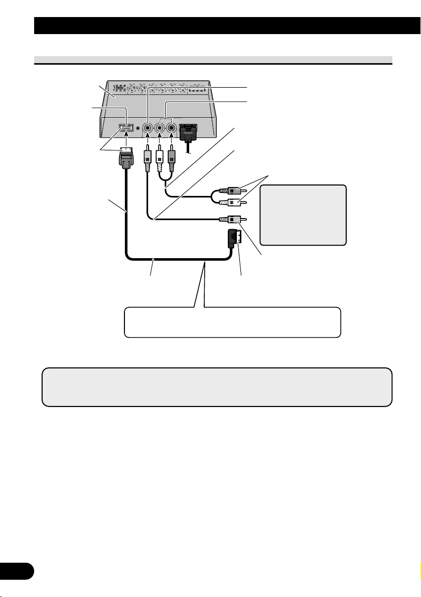
27
Conexión del sistema
Conexión de la salida de audio y vídeo
*: Utilice el cable de extensión de vídeo componente de 26 clavijas CD-CP301E para
extensión (3 m).
Unidad
oculta-alejada
Salida de vídeo
COMPONENT
(Azul)
Cable de vídeo componente de 26 clavijas
(CD-CP300) (vendido separadamente)*
A la entrada de vídeo componente (Blanco) de
una segunda unidad AVD-W1100V
Azul
3 m
Salida de vídeo RCA (Amarillo)
Salida de audio RCA (Blanco, Rojo)
Cable de audio RCA
(disponible comercialmente)
Cable de vídeo RCA
(disponible comercialmente)
A la entrada de audio
A la entrada de vídeo
Segunda pantalla,
reproductor de vídeo,
etc.
Puede conectar una segunda unidad AVD-W1100V con un
cable de vídeo componente de 26 clavijas CD-CP300 (vendido
separadamente).
Nota:
• Las señales de vídeo del terminal COMPONENT y las señales de audio/vídeo del terminal RCA
no se emiten cuando este producto está apagado.
Page 61

ENGLISH
ESPAÑOL
DEUTSCH
FRANÇAIS
ITALIANO
NEDERLANDS
кмллдав
28
Conexión con una unidad principal Pioneer con el cable
de vídeo componente
*: • Utilice el cable de vídeo componente de 26 clavijas CD-CP300 para productos
Pioneer.
• Utilice el cable de extensión de vídeo componente de 26 clavijas CD-CP301E para
extensión (3 m).
Azul
3 m
Cable de vídeo
componente
(vendido separadamente)*
Unidad oculta-alejada (AVH-P7800DVD)
(vendida separadamente)
Unidad oculta-alejada
Blanco
Entrada de vídeo
VCR1 COMPONENT
(Blanco)
Salida de vídeo COMPONENT (Azul)
Nota:
• Cuando vea DVD (reproductor DVD incorporado de la unidad AVH-P7800DVD) en la unidad
AVH-P7800DVD y en este producto, el audio no se emite desde el altavoz incorporado de este
producto.
Page 62

29
Instalación
PRECAUCIÓN
• Con respecto a las instrucciones sobre cómo instalar la pantalla, consulte
con su distribuidor.
• No instale la pantalla donde (i) pueda obstruir la visión del conductor, (ii)
afecte al rendimiento de cualquier sistema de funcionamiento o sistema de
seguridad del vehículo, incluyendo el air-bag, o (iii) afecte a la habilidad del
conductor para manejar con seguridad el vehículo.
• PIONEER no recomienda que sea usted mismo quien instale o revise su
pantalla. La instalación o revisión del producto puede exponerle a descargas
eléctricas u otros peligros. Solicite que todos los trabajos de instalación y
revisión de su pantalla los realice el personal de servicio PIONEER
autorizado.
• Instale la pantalla entre el asiento del conductor y el asiento del pasajero
delantero para que ésta no golpee al conductor o al pasajero si el vehículo
frena repentinamente.
• No instale la pantalla en una posición donde pueda obstruir el air-bag en
caso de inflarse éste completamente.
• No instale la pantalla en un lugar donde pueda afectar al rendimiento de
cualquier sistema de funcionamiento del vehículo, incluyendo el air-bag y
apoyacabezas.
• Asegúrese de que no haya nada detrás del salpicadero u otros paneles al
taladrar agujeros en ellos. Tenga cuidado para no estropear los conductos
de combustible, los conductos del líquido de frenos o los cables de
alimentación.
• Cuando utilice tornillos no permita que éstos entren en contacto con ningún
cable eléctrico. La vibración puede estropear los cables, causando un
cortocircuito u otros daños en el vehículo.
• Es peligrosísimo dejar que el cable de la pantalla se enrolle en la base del
volante o en la palanca de cambios. Asegúrese de instalar la pantalla de
forma que ésta no sea un obstáculo para la conducción.
• Asegúrese de que los cables no queden atrapados en una puerta ni en el
mecanismo de deslizamiento de un asiento porque puede producirse un
cortocircuito.
Page 63

ENGLISH
ESPAÑOL
DEUTSCH
FRANÇAIS
ITALIANO
NEDERLANDS
кмллдав
30
• Nunca instale este producto en un lugar donde quede visible al conductor del
vehículo. Dejar de hacer eso podría causar la distracción del conductor por
imágenes potencialmente visibles mientras el vehículo esté en movimiento.
El uso de este producto está sometido a las leyes gubernamentales vigentes
sobre su uso o emplazamiento.
PIONEER no asume responsabilidad alguna por ningún tipo de problemas,
daños o pérdidas resultantes de haber usado este producto con un ajuste
incorrecto o infringiendo las leyes gubernamentales.
• Para asegurar la instalación apropiada, utilice las piezas suministradas de la
manera especificada. Si se usa cualquier pieza diferente de las suministradas,
eso puede dañar las piezas internas de la unidad o las piezas pueden
aflojarse, soltando la unidad.
Antes de instalar y fijar la pantalla
• Haga primero conexiones provisionales para comprobar que la unidad y el sistema
funcionen correctamente.
• Presione el botón RESET con la punta de un bolígrafo u otro objeto similar después de
completar la conexión.
Antes de poner la cinta adhesiva
• Antes de fijar la cinta adhesiva asegúrese de que la superficie no tenga humedad, polvo,
suciedad, aceite, etc.
Page 64

31
Instalación
Instalación de la unidad oculta-alejada
Precauciones de instalación
• No instale nunca en lugares tales como los siguientes por causa del peligro de fallo de funcionamiento debido a altas temperaturas o humedad:
* Lugares tales como el tablero de instrumentos o la bandeja trasera, expuestos a los
rayos directos del sol.
* Cerca de las bocas de salida del calefactor.
* Cerca de las puertas, etc., donde existe el peligro de exposición a la lluvia.
• Asegúrese de que no obstaculice el deslizamiento del asiento cuando la instale debajo
del asiento delantero.
• La instalación directa sobre la alfombra es posible si la cinta Velcro dura puede
adherirse a la alfombra. En este caso, no utilice cinta Velcro blanda.
Instalación de la unidad oculta-alejada
Pegue la cinta Velcro (suministrada) sobre la parte inferior de la unidad oculta-alejada y
pegue la cinta Velcro blanda (suministrada) sobre el sitio de instalación.
Unidad oculta-alejada
Cinta Velcro (dura)
Cinta Velcro (blanda)
Alfombra del
automóvil
Page 65

32
Especificaciones
ENGLISH
ESPAÑOL
DEUTSCH
FRANÇAIS
ITALIANO
NEDERLANDS
кмллдав
General
Fuente de energía ................................................................ CC 14,4 V (10,8 V a 15,1 V permisible)
Sistema de conexión a tierra ................................................ Tipo negativo
Consumo de corriente máx. ................................................ 4,0 A
Rango de temperatura de almacenaje .................................. –20 °C a +80 °C
Unidad de visualización
Dimensiones ........................................................................ 297 (An.) × 181 (Al.) × 42 (Pr.) mm
Peso ...................................................................................... 1,39 kg
Tamaño de la pantalla/Razón de aspecto ............................ 11,0 pulgadas VGA ancho/16:9
(área de visualización efectiva: 245,6 × 139,5 mm)
Píxeles .................................................................................. 1 152 000 [800 (Horizontal) × 480 (Vertical) × 3 (RGB)]
Método de visualización ...................................................... Accionamiento de matriz activa TFT
Sistema de color .................................................................. Compatible con NTSC/PAL/SECAM
Altavoz incorporado ............................................................ ø 36 mm
Nivel de salida de los auriculares ........................................ 8 mW+8 mW/16 Ω
Rango de temperatura de funcionamiento .......................... –10 °C a +50 °C
Unidad oculta-alejada
Dimensiones ........................................................................ 178 (An.) × 157 (Al.) × 30 (Pr.) mm
Peso ...................................................................................... 0,68 kg
Nivel de entrada de vídeo .................................................... NTSC, PAL, SECAM 1 Vp-p/75 Ω
Nivel de entrada de audio máx. ..........................................1,5 V/22 kΩ
Nivel de salida de vídeo ......................................................NTSC, PAL, SECAM 1 Vp-p/75 Ω
Nivel de salida de audio máx. ............................................1,5 V/1 kΩ
Nivel de entrada de vídeo componente .............................. Y: 1 Vp-p/75 Ω
Cb, Cr: 0,7 Vp-p/75 Ω
Nivel de salida de vídeo componente .................................. Y: 1 Vp-p/75 Ω
Cb, Cr: 0,7 Vp-p/75 Ω
Rango de temperatura de funcionamiento .......................... –10 °C a +60 °C
Nota:
• Las especificaciones y el diseño están sujetos a cambios sin previo aviso. Los productos adquiridos pueden
ser diferentes, en pequeños detalles, de los mostrados en las ilustraciones de este manual.
Page 66

1
Inhalt
Inhalt ............................................................ 1
WICHTIGE SICHERHEITSHINWEISE........ 2
Bitte lesen sie diese Anleitung zum Einbau des
Farbdisplays aufmerksam durch und
bewahren Sie die Anleitung für späteres
Nachschlagen auf ...................................... 2
Befestigen und Entfernen des Displays.. 3
Befestigen des Displays .................................... 3
Entfernen des Displays ...................................... 4
WICHTIGE INFORMATION ........................ 5
Über dieses Produkt .......................................... 5
Registrierung des Produkts ................................ 5
Zur besonderen Beachtung ................................ 5
Im Störungsfalle ................................................ 5
Vor der Inbetriebnahme
dieses Produktes ................................ 6
Zur Vermeidung von Batterie-Erschöpfung ...... 6
Zum Schützen des LCD-Bildschirms
des Display.................................................. 6
Besseres Bild mit [BRIGHT] und [DIMMER].. 6
Zu den Video- und Audio-Ausgängen dieses
Geräts .......................................................... 6
Rückstellen des Systems .................................. 7
-
Rückstellen des Mikroprozessors
Tastenübersicht ........................................ 8
Bestandteile und Ausstattungsmerkmale .......... 8
Grundlegender Betrieb ............................ 9
Einschalten ........................................................ 9
Einstellung der Lautstärke .............................. 10
Wählen einer Programmquelle ........................ 11
Ändern des Breitbildmodus ............................ 12
-
Verfügbare Breitbildmodi
Bildschirm-Einstellungen ...................... 14
Bildeinstellung
(BRIGHT/CONTRAST/COLOR/HUE) .. 14
Bildeinstellung (DIMMER) ............................ 16
Einstellungen ............................................ 18
Eingangswahl (VCR1/VCR2) ........................ 18
Ein-/Ausschalt-Steuerfunktion ........................ 19
Richtiger Gebrauch des Displays ........ 20
Handhabung des Displays .............................. 20
Hinweise zur Flüssigkristallanzeige (LCD) .... 21
Pflege des Farbdisplays .................................. 21
Hinweise zur Leuchtröhre .............................. 21
Anschluss des Geräts ............................ 22
Bezeichnung und Funktion de
Anschlussbuchsen .................................. 24
Anschließen des Stromkabels .......................... 25
Anschlussschema (VIDEO-Eingang) .............. 26
Audio- und Video-Ausgangsanschluss ............ 27
Verbindung mit Pioneer-Haupteinheit über
Komponentenkabel .................................. 28
Einbau ........................................................ 29
Vor Einbau und Befestigung............................ 30
Vor der Verwendung des Klebebands.............. 30
Einbau der Hideaway-Einheit ........................ 31
-
Installationshinweise
-
Installation der Hideaway-Einheit
Technische Daten .................................... 32
Page 67

ENGLISH
ESPAÑOL
DEUTSCH
FRANÇAIS
ITALIANO
NEDERLANDS
кмллдав
2
WICHTIGE SICHERHEITSHINWEISE
Bitte lesen sie diese Anleitung zum Einbau des Farbdisplays aufmerksam
durch und bewahren Sie die Anleitung für späteres Nachschlagen auf
1. Bitte lesen Sie diese Anleitung vor dem Einbau des Farbdisplays
aufmerksam durch.
2. Bewahren Sie die Anleitung für späteres Nachschlagen auf.
3. Beachten Sie alle Warnungen in dieser Anleitung, und folgen Sie den hier
gegebenen Anweisungen genauestens.
4. Nicht anderen Personen erlauben, dieses Gerät zu verwenden, bevor diese
die Bedienungsanleitung gelesen haben.
5. Bringen Sie das Display nicht an Stellen an, wo es (i) die Sicht des Fahrers
beeinträchtigt, (ii) beim Führen des Fahrzeugs stört oder
Sicherheitseinrichtungen des Fahrzeugs wie etwa die Airbags in ihrer
Funktion behindert oder (iii) die Fähigkeit des Fahrers, das Fahrzeug sicher
zu steuern, beeinträchtigt.
6. Wie jedes andere Zubehör im Fahrgastraum Ihres Fahrzeugs, so sollte auch
das Display Ihre Aufmerksamkeit nicht vom sicheren Betrieb Ihres
Fahrzeugs ablenken. Falls Sie Schwierigkeiten mit der Bedienung des
Systems haben, parken Sie bitte an einem sicheren Ort, bevor Sie
Einstellungen durchführen.
7. Versuchen Sie niemals, das Display eigenhändig einzubauen oder zu warten.
Der Einbau oder die Wartung des Displays durch ungeschulte Personen, die
im Umgang mit elektronischer Ausrüstung und Fahrzeugzubehör keine
Erfahrung haben, setzt den Fahrer der Gefahr elektrischer Schläge und
anderer Verletzungen aus.
8. Beachten Sie bitte, beim Fahren stets den Sicherheitsgurt anzulegen. Nicht
korrekt angeschnallte Insassen sind bei einem Unfall einer wesentlich
höheren Verletzungsgefahr ausgesetzt.
9. Installieren Sie dieses Produkt auf keinen Fall an einer Stelle, wo es vom
Fahrer betrachtet werden kann. Anderenfalls könnte der Fahrer vom
Führen des Fahrzeugs abgelenkt werden.
Der Gebrauch dieses Produkts unterliegt jeglichen Landesgesetzen
hinsichtlich Platzierung und Nutzung.
PIONEER übernimmt keinerlei Verantwortung für jedwede Probleme,
Schäden oder Verluste, die auf den Gebrauch des Produkts mit falscher
Einrichtung oder unter Verletzung von Landesgesetzen zurückzuführen
sind.
Page 68

3
Befestigen und Entfernen des Displays
Hinweis:
• Der unten beschriebene Montagearm ist im Handel erhältlich. Bezüglich weiterer Informationen zur
Installation beziehen Sie sich bitte auf die Gebrauchsanweisung oder wenden Sie sich an Ihren
Händler.
Befestigen des Displays
1. Teil 1 der Halterung in die Kerben 2 des Unterbaus einpassen.
2. Das Display durch Schieben zum Einrasten bringen.
Vorsichtsmaßregeln:
• Um Beschädigungen zu vermeiden, den Zündschlüssel oder den Ein/Aus-Schalter des Systems
vor dem Befestigen oder Entfernen des Displays auf “OFF” stellen. Bei der Handhabung darauf
achten, den Bildschirm und die Tasten nicht mit zu festem Griff zu halten und das Display nicht
fallen zu lassen.
• Darauf achten, dass kein Wasser an die Anschlüsse des Displays und des Kabels gelangt und
dass die Anschlüsse nicht mit Metallobjekten in Berührung kommen, die einen Kurzschluss
verursachen können. Andernfalls kann es zum Ausfall des Systems kommen.
• Die Anschlüsse des Displays und des Kabels nicht berühren, da hierdurch Anschlussstörungen
auftreten können. Verschmutzte Anschlüsse sollten mit einem trockenen, sauberen Tuch
abgewischt werden.
Unterbau
Halterung
Montagearm
(im Handel erhältlich)
Den
Halterungsanschlag
an der Halterung
anbringen, bevor
diese am Display
montiert wird.
Halterungsanschlag
Das Kabel an das Display
anschließen.
Page 69

4
ENGLISH
ESPAÑOL
DEUTSCH
FRANÇAIS
ITALIANO
NEDERLANDS
кмллдав
Entfernen des Displays
• Den Freigabehebel 3 ziehen und gezogen halten, dann das Display vom
Unterbau abziehen.
• Um einen Diebstahl des Displays zu verhüten, das Display vor dem Verlassen des
Wagens abnehmen.
Unterbau
Montagearm
(im Handel erhältlich)
Die Freigabetaste drücken.
Den Steckverbinder trennen,
während die Taste gedrückt
gehalten wird.
Page 70

5
WICHTIGE INFORMATION
Privathaushalte in den 25 Mitgliedsstaaten der EU, in der Schweiz und in Norwegen können
ihre gebrauchten elektronischen Produkte an vorgesehenen Sammeleinrichtungen kostenfrei
zurückgeben oder aber an einen Händler zurückgeben (wenn sie ein ähnliches neues Produkt
kaufen).
Bitte wenden Sie sich in den Ländern, die oben nicht aufgeführt sind, hinsichtlich der
korrekten Verfahrensweise der Entsorgung an die örtliche Kommunalverwaltung.
Auf diese Weise stellen Sie sicher, dass das zu entsorgende Produkt der notwendigen
Behandlung, Rückgewinnung und Wiederverwertung unterzogen wird, und so mögliche
negative Einflüsse auf die Umwelt und die menschliche Gesundheit vermieden werden.
Mischen Sie dieses Produkt, wenn Sie es entsorgen wollen, nicht mit gewöhnlichen
Haushaltsabfällen. Es gibt ein getrenntes Sammelsystem für gebrauchte elektronische
Produkte, über das die richtige Behandlung, Rückgewinnung und Wiederverwertung
gemäß der bestehenden Gesetzgebung gewährleistet wird.
Über dieses Produkt
• Das Display darf nicht an einer Stelle angebracht werden, an der es die freie Sicht des
Fahrers einschränkt oder die Funktion der Airbags bzw. der Kopfstützen des Fahrzeugs
beeinträchtigt.
• Dieses Produkt ist ausschließlich zur Benutzung durch Rücksitzpassagiere konzipiert.
Installieren Sie das Display niemals an einer Stelle, wo der Fahrer das Bild während der
Fahrt sehen kann.
VORSICHT
Achten Sie darauf, dass dieses Produkt nicht mit Flüssigkeiten in Berührung
gelangt. Anderenfalls können elektrische Schläge verursacht werden.
Berührung mit Flüssigkeiten kann auch zu einer Beschädigung,
Rauchabgabe und Überhitzung des Produkts führen.
Registrierung des Produkts
Besuchen Sie uns bitte auf der folgenden Seite:
• Registrieren Sie Ihr Produkt. Wir speichern Ihre Angaben und geben Ihnen Zugriff zu
diesen Informationen, falls Sie sie für einen Versicherungsanspruch wegen Verlustes
oder Diebstahls benötigen sollten.
•
Auf unserer Webseite finden Sie auch die neuesten Informationen über Pioneer Corporation.
Zur besonderen Beachtung
• Halten Sie die Lautstärke stets auf einem Pegel, bei dem Sie Außengeräusche noch gut
wahrnehmen können.
• Setzen Sie das Gerät keiner Feuchtigkeit aus.
Im Störungsfalle
Falls dieses Gerät nicht richtig funktionieren sollte, wenden Sie sich bitte an Ihren Händler
oder an eine Pioneer-Kundendienststelle in Ihrer Nähe.
Page 71

Zur Vermeidung von Batterie-Erschöpfung
Benutzen Sie dieses Gerät nur bei laufendem Motor. Die Benutzung dieses Gerätes bei
abgestelltem Motor kann zu Erschöpfung der Batterie führen.
Zum Schützen des LCD-Bildschirms des Display
• Achten Sie darauf, dass bei Nichtbenutzung dieses Gerätes kein direktes Sonnenlicht auf
das Display fällt. Längere Einwirkung von direktem Sonnenlicht kann zu einer
Funktionsstörung des LCD-Bildschirms aufgrund der resultierenden hohen
Temperaturen führen.
• Bei Gebrauch eines Mobiltelefons ist dessen Antenne in ausreichendem Abstand vom
Display zu halten, um Bildstörungen, wie z.B. das Auftreten von Flecken, Farbstreifen
usw. zu vermeiden.
Besseres Bild mit [BRIGHT] und [DIMMER]
Der Betrachtungswinkel ist aufgrund der Bauweise des LCD-Bildschirms beschränkt. Der
Betrachtungswinkel (vertikal und horizontal) kann vergrößert werden, mit [BRIGHT] lässt
sich die Video-Schwarzdichte jedoch vorteilhaft einstellen. Stellen Sie die Schwarzdichte
beim erstmaligen Gebrauch dem Betrachtungswinkel (vertikal und horizontal)
entsprechend auf das beste Bild ein. Sie können auch [DIMMER] einsetzen, um die
Helligkeit des LCD-Bildschirms selbst wunschgemäß einzustellen.
Zu den Video- und Audio-Ausgängen dieses Geräts
Wenn Sie ein separates AV-Gerät, wie z.B. ein anderes Display, an COMPONENT OUT
oder VCR OUT (RCA-Video- und -Audio-Ausgang) der Hideaway-Einheit anschließen,
können Sie die Ausgabequelle mit der Taste SOURCE/POWER wählen.
• Video- und Audio-Programmquelle der COMPONENT/RCA-Ausgänge dieses Geräts
können nicht unabhängig gewählt werden.
• Die Tasten VOL– und VOL+ haben keine Wirkung, auch wenn sie betätigt werden.
VORSICHT
Platzieren Sie das Display niemals an einer Stelle, wo der Fahrer das Bild
während der Fahrt sehen kann.
6
Vor der Inbetriebnahme dieses Produktes
ENGLISH
ESPAÑOL
DEUTSCH
FRANÇAIS
ITALIANO
NEDERLANDS
кмллдав
Page 72
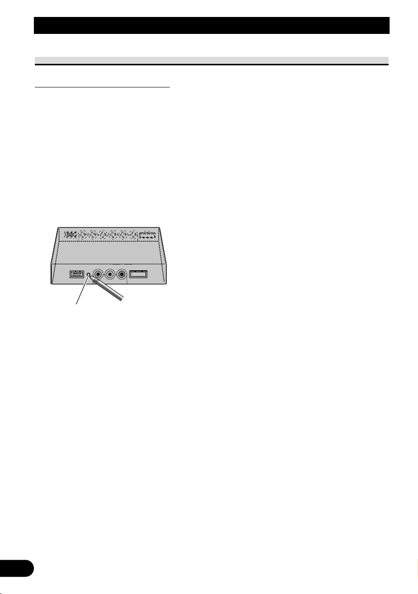
7
Vor der Inbetriebnahme dieses Produktes
Rückstellen des Systems
Rückstellen des Mikroprozessors
Durch Drücken des Rückstellknopfs (RESET) wird der Mikroprozessor auf die
anfänglichen Einstellungen rückgestellt, alle gespeicherten Einstellungen werden gelöscht,
und die Setup-Funktion wird auf die anfänglichen Werte (Werkseinstellungen)
zurückgesetzt.
Eine Rückstellung des Mikroprozessors führen Sie in den folgenden Fällen durch:
Bei der erstmaligen Inbetriebnahme nach dem Einbau dieses Produkts.
Wenn das Gerät nicht einwandfrei funktioniert.
Wenn ungewöhnliche (fehlerhafte) Meldungen im Display erscheinen.
• Zum Rückstellen des Mikroprozessors drücken Sie den RESET-Knopf an
der Hideaway-Einheit mithilfe der Spitze eines Kugelschreibers oder eines
anderen geeigneten spitzen Gegenstands.
RESET-Knopf
Page 73

ENGLISH
ESPAÑOL
DEUTSCH
FRANÇAIS
ITALIANO
NEDERLANDS
кмллдав
8
Tastenübersicht
Bestandteile und Ausstattungsmerkmale
7 Display-Einheit
1 Eingebauter Lautsprecher
Gibt den Ton von der an diesem
Produkt angeschlossenen AudioAusrüstung aus.
2 Kopfhörerbuchse
Zum Anschluss eines Kopfhörers mit
3,5-mm-Stereo-Ministecker.
3 Helligkeitssensor
Erkennt die Umgebungshelligkeit. Bei
diesem System passt sich die Helligkeit
des LCD-Bildschirms automatisch der
Umgebungshelligkeit an.
4 Taste SOURCE/POWER
Schaltet zwischen Programmquellen
um.
Zum Ein- und Ausschalten des
Produkts.
5 Tasten VOL– und VOL+
Zur Einstellung der Lautstärke des
eingebauten Lautsprechers 1 bzw. der
Lautstärke eines angeschlossenen
Kopfhörers.
Die Einstellungen können bei
angezeigter Setup-Funktion geändert
werden.
Hinweis:
• Die Lautstärke darf niemals so hoch
eingestellt werden, dass
Umgebungsgeräusche und Notfahrzeuge
nicht mehr wahrgenommen können.
6 Taste WIDE/MENU
Ändert das VideoVergrößerungsverfahren von 4:3 zu
16:9. Durch Gedrückthalten dieser
Taste wird das Setup-Menü oder das
Bildeinstellmenü zur Anzeige gebracht.
Bei Anzeige des Setup-Menüs oder des
Bildeinstellmenüs erfolgt mit jedem
Druck auf die Taste eine
Funktionsumschaltung.
1 2
3 4 5 6
Page 74

VORSICHT
Installieren Sie dieses Produkt auf keinen Fall an einer Stelle, wo es vom
Fahrer betrachtet werden kann. Anderenfalls könnte der Fahrer vom
Führen des Fahrzeugs abgelenkt werden.
Der Gebrauch dieses Produkts unterliegt jeglichen Landesgesetzen
hinsichtlich Platzierung und Nutzung.
PIONEER übernimmt keinerlei Verantwortung für jedwede Probleme,
Schäden oder Verluste, die auf den Gebrauch des Produkts mit falscher
Einrichtung oder unter Verletzung von Landesgesetzen zurückzuführen
sind.
Einschalten
Um Batteriestrom zu sparen, sollten Sie vor dem Einschalten des Systems stets den Motor
Ihres Fahrzeugs starten.
1. Starten Sie den Motor des Fahrzeugs.
2. Schalten Sie das System ein.
Drücken Sie die Taste SOURCE/POWER.
Zum Ausschalten des Systems drücken Sie die Taste SOURCE/POWER und halten Sie sie
gedrückt.
9
Grundlegender Betrieb
O
N
C
S
C
T
A
A
K
C
O
L
R
T
Page 75

ENGLISH
ESPAÑOL
DEUTSCH
FRANÇAIS
ITALIANO
NEDERLANDS
кмллдав
10
Einstellung der Lautstärke
Stellen Sie die Lautstärke des Audio-Ausgangs vom eingebauten Lautsprecher ein.
1. Stellen Sie die Lautstärke des Lautsprechers ein.
Drücken Sie die Taste VOL– oder VOL+.
VOL+: Lauter
VOL–: Leiser
Die Lautstärke des eingebauten Lautsprechers kann zwischen 0 und 30 eingestellt werden.
Hinweis:
• Wenn ein Kopfhörer angeschlossen ist, kann dessen Lautstärke mit den Tasten VOL– und VOL+
eingestellt werden.
• Durch den Anschluss eines Kopfhörers wird der Ton vom eingebauten Lautsprecher stummgeschaltet.
VOL12
Page 76

11
Wählen einer Programmquelle
Umschaltung von Video- und Audio-Eingängen von an VCR1 IN, VCR2 IN oder
COMPONENT IN angeschlossener AV-Ausrüstung.
1. Wählen Sie eine Programmquelle.
Drücken Sie die Taste SOURCE/POWER. Mit jedem Druck auf die Taste wird die
Programmquelle in der nachstehenden Reihenfolge weitergeschaltet:
[VCR1 (COMPONENT)] oder [VCR1] = [VCR2] = Verlassen zu [VCR1
(COMPONENT)] oder [VCR1]
Hinweis:
• Dieses Produkt verfügt über zwei Programmquelleneingänge: VCR1 IN und VCR2 IN.
VCR1 IN umfasst einen Komponenten-Video-Eingang [VCR1(COMPONENT)] und einen RCAVideo-Eingang [VCR1].
• Bei [VCR1 (COMPONENT)] handelt es sich um Komponenten-Video von an VCR1 IN
COMPONENT angeschlossener AV-Ausrüstung. Ein im Handel erhältliches 26-PinKomponentenkabel (CD-CP300) wird benötigt. (Siehe Seite 28.)
• Der Eingang VCR1 COMPONENT erhält Vorrang gegenüber dem Eingang VCR1 RCA, wenn
beide Eingänge gleichzeitig angeschlossen sind.
• Ein Video-Eingang, an dem keine Verbindung hergestellt ist, kann nicht gewählt werden, auch
wenn die Taste SOURCE/POWER betätigt wird.
• [VCR1] wird gewählt, wenn weder für den Eingang VCR1 noch für den Eingang VCR2 eine
Verbindung hergestellt ist.
VCR1[COMPONENT
]
Grundlegender Betrieb
Page 77

Ändern des Breitbildmodus
Sie können das Verfahren wählen, auf das das normale Video (Bildverhältnis 4:3) zum
Breitbild (16:9) vergrößert wird. Wählen Sie einen Breitbildmodus, der am besten zum
jeweiligen Video passt.
1. Bringen Sie eine Programmquelle zur Anzeige. (Siehe Seite 11.)
2. Wählen Sie einen Breitbildmodus.
Mit jedem Druck auf die Taste WIDE/MENU wird der Breitbildmodus in der
nachstehenden Reihenfolge weitergeschaltet:
[AUTO] oder [FULL] = [JUST] = [CINEMA] = [ZOOM] = [NORMAL] =
Verlassen zu [AUTO] oder [FULL]
Hinweis:
• Die Einstellungen werden für jede Programmquelle (COMPONENT, VCR1 oder VCR2)
gespeichert.
• Wird Video in einem Breitbildmodus betrachtet, der nicht dem ursprünglichen Bildverhältnis
entspricht, können Bildunterschiede auftreten.
• [AUTO] kann nur dann gewählt werden, wenn die AV-Ausrüstung am Video-Eingang
COMPONENT IN angeschlossen ist. Wenn das Videosignal Informationen zum Breitbildmodus
enthält, wird dieser automatisch entsprechend eingestellt.
• Bitte beachten Sie, dass der Gebrauch der Breitbildfunktion dieses Systems für kommerzielle
Zwecke bzw. öffentliche Darbietungen eine Verletzung der Urheberrechte des Autors darstellen
kann.
FULL
12
ENGLISH
ESPAÑOL
DEUTSCH
FRANÇAIS
ITALIANO
NEDERLANDS
кмллдав
Page 78

13
Grundlegender Betrieb
Verfügbare Breitbildmodi
Hinweis:
• Die Bildqualität verschlechtert sich bei Betrachtung im Modus CINEMA oder ZOOM.
NORMAL (NORMAL)
Bilder mit einem Seitenverhältnis
von 4:3 werden unverändert
angezeigt. Fernsehprogramme
werden im gesendeten Bildformat
wiedergegeben.
ZOOM (ZOOM)
Bilder im Bildformat 4:3 werden mit
unverändertem Seitenverhältnis in
vertikaler und horizontaler Richtung
gedehnt. Dieser Breitbildmodus eignet
sich für horizontal gestreckte Bilder, wie
z.B. bei Filmen, bei denen Untertitel mit
der Bildfläche überlappen.
CINEMA (KINO)
Das Bild wird vertikal auf ein
Seitenverhältnis zwischen FULL und
ZOOM gedehnt. Dieser
Breitbildmodus eignet sich für
horizontal gestreckte Bilder, wie z.B.
bei Filmen, bei denen Untertitel in den
schwarzen Bereichen außerhalb der
Bildfläche angezeigt werden.
JUST (JUSTIERT)
Das Bild wird zu beiden
Seitenrändern hin zunehmend
horizontal gedehnt. Da das Bild in
Bildschirmmitte annähernd im
Normalformat erscheint, kann es
ohne ein Gefühl der
Unnatürlichkeit betrachtet werden.
FULL (VOLL)
Bilder mit einem Seitenverhältnis
von 4:3 werden nur horizontal
gedehnt. Programme können im
Breitbildformat ohne fehlende Teile
wiedergegeben werden.
Page 79
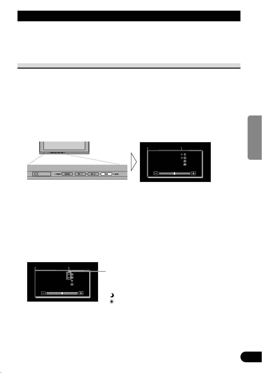
ENGLISH
ESPAÑOL
DEUTSCH
FRANÇAIS
ITALIANO
NEDERLANDS
кмллдав
14
Bildschirm-Einstellungen
Dieses System bietet zahlreiche Funktions-, Einrichtungs- und Einstellmerkmale zur
Bedienungserleichterung. Die Einstellungen können je nach Bevorzugung und Umgebung
angepasst werden.
Bildeinstellung (BRIGHT/CONTRAST/COLOR/HUE)
Sie können die Helligkeit [BRIGHT] des Schwarzanteils, den Kontrast [CONTRAST], die
Dunkelheit der Farben [COLOR] und den Farbton [HUE] des Bilds wunschgemäß ändern.
Für Video von VCR1 (COMPONENT), VCR1 und VCR2 werden jeweils eigene
Einstellungen gespeichert.
1. Bringen Sie eine Programmquelle zur Anzeige. (Siehe Seite 11.)
2. Bringen Sie ein Menü zur Anzeige.
Drücken Sie die Taste WIDE/MENU und halten Sie sie mindestens 2 Sekunden lang
gedrückt.
Die Bildschirmanzeige [PICTURE ADJUST] erscheint.
3. Wählen Sie einen Einstellpunkt.
Drücken Sie die Taste WIDE/MENU. Der gewählte Punkt wird blau.
Mit jedem Druck auf die Taste WIDE/MENU wird der Einstellpunkt in der nachstehenden
Reihenfolge weitergeschaltet:
[BRIGHT] = [CONTRAST] = [COLOR] = [HUE] = [DIMMER] = Verlassen zu
[BRIGHT]
4. Stellen Sie den Punkt ein.
Drücken Sie die Taste VOL– oder VOL+.
VOL+: Erhöht Werte.
VOL–: Vermindert Werte.
Jeder Punkt kann zwischen –24 und +24 eingestellt werden.
Der Helligkeitssensor des Displays erkennt die
Umgebungshelligkeit und zeigt ein Symbol zur
Kennzeichnung der aktuellen Helligkeit an.
(blau): wenn es dunkel ist (nachts)
(rot) : wenn es hell ist (untertags)
COLOR
BRIGHTBRIGHT
CONTRAST
HUE
DIMMER
CONTRAST
HUE
DIMMER
PICTURE ADJUST
0
0
0
0
0
0
5
PICTURE ADJUST
BRIGHT
CONTRAST
COLOR
HUE
DIMMER
CONTRAST
COLOR
HUE
DIMMER
0
000
0
00
Page 80

15
Bildschirm-Einstellungen
5. Die Einstellung beenden.
Zum Schließen des Menüs und Beenden der Einstellung drücken Sie die Taste
WIDE/MENU und halten Sie sie mindestens 2 Sekunden lang gedrückt.
Einstellpunkt Seite – Seite +
BRIGHT Schwarzwert Schwarz erscheint dunkler. Schwarz erscheint heller.
CONTRAST Kontrast
Der Abstand zwischen Schwarz Der Abstand zwischen Schwarz
und Weiß wird kleiner (dunkler). und Weiß wird größer (heller).
COLOR Farbsättigung Farben erscheinen blasser. Farben erscheinen kräftiger.
HUE Farbton Rot wird verstärkt. Grün wird verstärkt.
Hinweis:
• Die Einstellungen von [BRIGHT] und [CONTRAST] werden für helle Umgebung (Tag) und
dunkle Umgebung (Nacht) getrennt gespeichert.
• Eine rote Markierung ( ) oder eine blaue Markierung ( ) erscheint jeweils rechts von
[BRIGHT] und [CONTRAST] am Bildschirm, je nachdem, ob der Umgebungslichtsensor
Helligkeit oder Dunkelheit erkennt.
• Wenn innerhalb von etwa 30 Sekunden nach Erscheinen des Bildeinstellmenüs kein
Bedienungsschritt vorgenommen wird, erlischt die Menü-Bildschirmanzeige.
• [HUE] kann nur für NTSC-Video eingestellt werden.
Page 81

ENGLISH
ESPAÑOL
DEUTSCH
FRANÇAIS
ITALIANO
NEDERLANDS
кмллдав
16
Bildeinstellung (DIMMER)
Die Sichtbarkeit kann sich bei längerer Video-Wiedergabe verschlechtern, wenn der
Bildschirm bei Dunkelheit zu hell ist, oder wenn die Umgebung dunkel wird. Dieses Gerät
passt die Helligkeit des LCD-Bildschirms automatisch der Umgebungshelligkeit an
(intelligenter 3-Stufen-Dimmer). Die automatisch eingestellte Helligkeit kann auch auf die
gewünschte Helligkeit korrigiert werden.
1. Bringen Sie ein Menü zur Anzeige.
Führen Sie die Schritte 1 und 2 unter “Bildeinstellung
(BRIGHT/CONTRAST/COLOR/HUE)” aus. (Siehe Seite 14.)
2. Wählen Sie [DIMMER].
Drücken Sie die Taste WIDE/MENU wiederholt, bis [DIMMER] gewählt ist.
Hinweis:
• Der als Norm für die Einstellung von [DIMMER] verwendete externe Lichtpegel wird durch das in
Schritt 2 gezeigte Symbol und seine Position angezeigt. Die Symbole, welche die momentane
Umgebungshelligkeit zur Einstellung von [BRIGHT] und [CONTRAST] anzeigen, können
geringfügig unterschiedlich sein.
Blau: dunkel (Nacht)
Der Helligkeitssensor des Monitorschirms
erkennt die Umgebungshelligkeit und passt
Farbe, Form und Position des Symbols der
momentanen Helligkeit (externer Lichtpegel) an.
DIMMER
PICTURE ADJUST
CONTRAST
COLOR
HUE
CONTRAST
COLOR
HUE
BRIGHTBRIGHT
0
0
5
0
0
0
5
0
Gelb: hell (Tag)
Rot: mittlere Helligkeit (Abend)
Page 82

17
3. Die Helligkeit einstellen.
Drücken Sie die Taste VOL– oder VOL+.
VOL+: Heller.
VOL–:Dunkler.
Je weiter das gelbe Symbol nach rechts wandert, desto heller wird der Bildschirm.
• Der momentane externe Lichtpegel wird festgelegt, und die Bildschirmhelligkeit wird
eingestellt.
• Der externe Lichtpegel kann auf Dark, Intermediate oder Bright eingestellt werden, und
die Einstellung kann gespeichert werden.
4. Die Einstellung beenden.
Zum Schließen des Menüs und Beenden der Einstellung drücken Sie die Taste
WIDE/MENU und halten Sie sie mindestens 2 Sekunden lang gedrückt.
Hinweis:
• Wenn innerhalb von etwa 30 Sekunden nach Erscheinen des Bildeinstellmenüs kein
Bedienungsschritt vorgenommen wird, erlischt die Menü-Bildschirmanzeige.
Dieser Pegel zeigt die eingestellte Helligkeit des Bildschirms an.
Je weiter das gelbe Symbol nach rechts wandert, desto heller wird der Bildschirm.
Auf dieser Anzeige kann die
Helligkeitseinstellung des Bildschirms bei
Dunkelheit ( ) geändert werden.
DIMMER
PICTURE ADJUST
CONTRASTCONTRAST
COLORCOLOR
HUEHUE
CONTRAST
COLOR
HUE
BRIGHTBRIGHTBRIGHT
0
0
5
0
0
0
5
0
Bildschirm-Einstellungen
Page 83
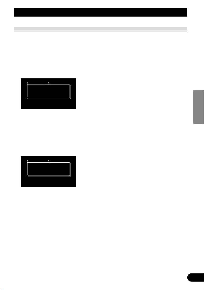
ENGLISH
ESPAÑOL
DEUTSCH
FRANÇAIS
ITALIANO
NEDERLANDS
кмллдав
18
Einstellungen
Eingangswahl (VCR1/VCR2)
Videoformate wie z.B. NTSC, PAL und SECAM können je nach Format der an diesem
Gerät angeschlossenen AV-Ausrüstung gewählt werden.
1. Schalten Sie das System aus.
Drücken Sie die Taste SOURCE/POWER und halten Sie sie gedrückt.
2. Bringen Sie ein Setup-Menü zur Anzeige.
Drücken Sie die Taste WIDE/MENU und halten Sie sie mindestens 2 Sekunden lang
gedrückt. Die Bildschirmanzeige [SETUP MENU] erscheint. [VCR1] ist bereits gewählt.
3. Wählen Sie zwischen [VCR1] und [VCR2].
Drücken Sie die Taste WIDE/MENU. Der gewählte Punkt wird blau.
4. Wählen Sie das Videoformat.
Drücken Sie die Taste VOL+. Das Videosystem wird umgeschaltet.
Mit jedem Druck auf die Taste VOL+ wird der Einstellpunkt in der nachstehenden
Reihenfolge weitergeschaltet:
[AUTO] = [NTSC] = [PAL] = [SECAM] = Verlassen zu [AUTO]
Hinweis:
• Durch Drücken der Taste VOL– erfolgt die Wahl in der umgekehrten Reihenfolge der Taste VOL+.
5. Bringen Sie die Einstellung zum Abschluss.
Zum Schließen des Menüs und Beenden der Einstellung drücken Sie die Taste
WIDE/MENU und halten Sie sie mindestens 2 Sekunden lang gedrückt.
Hinweis:
• Bei Wahl von [AUTO] werden NTSC, PAL und SECAM automatisch identifiziert und
entsprechend angezeigt.
• Bei Wahl von [AUTO] kann es zu verminderter Empfangsqualität kommen.
• Wenn innerhalb von etwa 30 Sekunden nach Erscheinen des Setup-Menüs kein Bedienungsschritt
vorgenommen wird, erlischt die Menü-Bildschirmanzeige.
SETUP MENU
VCR1
VCR2 AUTO
NORMAL
VCR2
PAL
AUTO
NORMALPOWER . CPOWER . C
SETUP MENU
VCR1
VCR2 AUTO
NORMAL
VCR2
AUTO
AUTO
NORMALPOWER . CPOWER . C
Page 84

19
Ein-/Ausschalt-Steuerfunktion
Bei Verbindung mit einem Hauptgerät, das über eine Ein-/Ausschalt-Steuerfunktion
verfügt, wie z.B. AVH-P7800DVD, kann das AVD-W1100V über das Hauptgerät ein- und
ausgeschaltet werden.
1. Bringen Sie ein Setup-Menü zur Anzeige.
Führen Sie die Schritte 1 und 2 unter “Eingangswahl (VCR1/VCR2)” durch.
(Siehe Seite 18.)
2. Wählen Sie [POWER.C].
Drücken Sie die Taste WIDE/MENU. Der gewählte Punkt wird blau.
3. Wählen Sie Ein-/Ausschalt-Steuerfunktion.
VOL–: [NORMAL]
Sie können dieses Gerät durch Drücken der Taste SOURCE/POWER
ein-/ausschalten.
VOL+: [FRONT]
Sie können dieses Gerät durch Drücken der Taste SOURCE/POWER NICHT
ein-/ausschalten.
Die Ein-/Ausschalt-Steuerung erfolgt über ein Hauptgerät, das mit dieser Funktion
ausgestattet und mit dem 26-Pin-Komponentenkabel CD-CP300 angeschlossen ist.
(im Handel erhältlich)
z.B. bei Verbindung mit AVH-P7800DVD.
Durch Drücken der Taste REAR ON am AVH-P7800DVD wird dieses Gerät
eingeschaltet. Drücken Sie die Taste am AVH-P7800DVD und halten Sie sie
gedrückt, um das Gerät auszuschalten.
4. Bringen Sie die Einstellung zum Abschluss.
Zum Schließen des Menüs und Beenden der Einstellung drücken Sie die Taste
WIDE/MENU und halten Sie sie mindestens 2 Sekunden lang gedrückt.
Hinweis:
• Wenn innerhalb von etwa 30 Sekunden nach Erscheinen des Setup-Menüs kein Bedienungsschritt
vorgenommen wird, erlischt die Menü-Bildschirmanzeige.
SETUP MENU
VCR1VCR1 AUTAUTOVCR1
VCR2VCR2
POWER . C
AUTAUTO
NORMAL
VCR2
AUTO
AUTO
Einstellungen
Page 85

ENGLISH
ESPAÑOL
DEUTSCH
FRANÇAIS
ITALIANO
NEDERLANDS
кмллдав
20
Richtiger Gebrauch des Displays
VORSICHT
• Falls Feuchtigkeit oder Fremdkörper in das Display-Gehäuse eindringen,
das Display sofort ausschalten (OFF) und an einen Fachhändler oder die
nächstgelegene PIONEER-Kundendienststelle wenden. Der fortgesetzte
Betrieb des Displays in diesem Zustand kann zu Bränden, elektrischen
Schlägen oder zum Ausfall des Geräts führen.
• Bei Rauchentwicklung, fremden Geräuschen oder Gerüchen, oder sonstigen
anormalen Betriebserscheinungen, das Display sofort ausschalten (OFF) und
an einen Fachhändler oder die nächstgelegene PIONEERKundendienststelle wenden. Der fortgesetzte Betrieb des Displays in diesem
Zustand kann zum Ausfall des Systems führen.
• Die Rückwand des Displays nicht entfernen, da sich im Inneren des Displays
Hochspannungsschaltungen befinden, die elektrische Schläge verursachen
können. Für eine Inspektion der Innenbauteile, Einstellungen oder
Reparaturen bitte an einen Fachhändler oder die nächstgelegene PIONEERKundendienststelle wenden.
Handhabung des Displays
• Bei Nichtgebrauch darf das Display auf keinen Fall direkter Sonnenbestrahlung oder
extremen Temperaturen ausgesetzt bleiben.
• Als Umgebungstemperaturbereich für das Display gelten die folgenden Bereiche:
Betriebstemperaturbereich: –10 °C bis +50 °C
Lagerungstemperaturbereich: –20 °C bis +80 °C
Bei höheren oder niedrigeren Temperaturen können beim Betrieb des Displays
Funktionsstörungen auftreten.
• Zugunsten optimaler Sichtbarkeit im Auto verfügt das Display über einen freiliegenden
LCD-Schirm. Darauf achten, nicht fest auf den Bildschirm zu drücken, da dieser bei zu
starker Belastung brechen kann.
• Den LCD-Schirm nicht berühren, um Kratzer und Verschmutzung zu vermeiden.
Page 86

Hinweise zur Flüssigkristallanzeige (LCD)
• Wenn das Display in der Nähe des Auslasses einer Klimaanlage installiert wird, ist
darauf zu achten, dass die Luft von der Klimaanlage nicht direkt auf das Display trifft.
Warmluft kann zu einer Beschädigung des LCD-Bildschirms führen, Kaltluft kann
Kondensatbildung im Inneren des Displays mit daraus resultierenden Störungen
verursachen. Wenn das Display durch Kaltluft abgekühlt wird, kann der Bildschirm
auch dunkel werden, und die Lebensdauer der kleinen Leuchtstoffröhre im Inneren des
Displays könnte sich verkürzen.
• Auf dem Bildschirm können kleine schwarze oder weiße Punkte (helle Punkte)
erscheinen. Es handelt sich hierbei um eine normale Erscheinung von LCDBildschirmen und deutet nicht auf einen anormalen Betriebszustand hin.
• Bei niedrigen Temperaturen kann es vorkommen, dass der LCD-Schirm nach dem
Einschalten (ON) des Displays zunächst eine Weile dunkel bleibt.
• Das Bild auf dem LCD-Schirm ist bei direkt auftreffendem Sonnenlicht schwer zu
erkennen.
Pflege des Farbdisplays
• Vor dem Entfernen von Staub auf dem Bildschirm oder Säubern des Displays zuerst die
Stromversorgung zum System ausschalten (OFF), und das Display anschließend mit
einem weichen Tuch sauber wischen.
• Beim Abwischen des Bildschirms darauf achten, die Oberfläche nicht zu verkratzen und
keine ätzenden oder schleifenden chemischen Reinigungsmittel zu verwenden.
• Verwenden Sie kein nasses Tuch zum Reinigen. Verwenden Sie auch keine organischen
Lösungsmittel, wie Benzol und Verdünner.
Hinweise zur Leuchtröhre
• Im Display befindet sich eine kleine Leuchtröhre zur Beleuchtung des LCD-Schirms.
* Die Leuchtstoffröhre ist ein Verschleißteil und hat eine begrenzte Lebensdauer.
* Die Lebensdauer der Leuchtstoffröhre beträgt etwa 10 000 Stunden und hängt von
den jeweiligen Betriebsbedingungen ab. (Gebrauch des Displays bei niedrigen
Temperaturen führt zu einer Verminderung der Lebensdauer der Leuchtstoffröhre.)
* Am Ende der Betriebslebensdauer der Leuchtröhre ist das Schirmbild schwarz und
nicht mehr sichtbar. Wenden Sie sich in diesem Fall bitte an einen Fachhändler oder
die nächstgelegene PIONEER-Kundendienststelle.
21
Richtiger Gebrauch des Displays
Page 87

22
Anschluss des Geräts
ENGLISH
ESPAÑOL
DEUTSCH
FRANÇAIS
ITALIANO
NEDERLANDS
кмллдав
VORSICHT
• PIONEER rät nachdrücklich davon ab, das Display eigenhändig einzubauen
oder zu warten, da hierbei die Möglichkeit elektrischer Schläge und anderer
Gefahren besteht. Einbau und Wartung des Displays sind deshalb dem
autorisierten Kundendienst-Fachpersonal zu überlassen.
• Alle Kabel mit Kabelklemmen oder Isolierband befestigen. Es dürfen keine
offenliegenden Drähte vorhanden sein.
• Kein Loch in den Motorraum bohren, um das gelbe Kabel des Geräts an die
Fahrzeugbatterie anzuschließen: Die Kabelisolierung kann am Übergangspunkt von Insassenraum zum Motorraum durch die Vibration des
Motors beschädigt werden. Darauf achten, das Kabel in diesem Bereich
besonders gut zu befestigen.
• Es ist äußerst gefährlich das Display-Kabel um die Lenksäule oder den
Gangschalthebel zu wickeln. Beim Einbau unbedingt darauf achten, dass das
Display den Fahrer nicht behindert.
• Vergewissern, dass die Kabel keine beweglichen Teile des Fahrzeugs, wie
z.B. Gangschalthebel, Handbremse oder Sitzverstellmechanismus, berühren.
• Kabel sollten grundsätzlich nicht gekürzt werden. Andernfalls funktioniert
die Schutzschaltung eventuell nicht ordnungsgemäß.
Page 88

23
Anschluss des Geräts
Hinweis:
• Diese Einheit ist für Fahrzeuge mit 12-V-Batterie
und negativer Erdung (Minuspol an Masse)
ausgelegt. Prüfen Sie vor dem Einbau in ein
Wohnmobil, einen Lastwagen oder Bus die
Batteriespannung.
• Um einen Kurzschluss in der elektrischen Anlage
zu vermeiden, klemmen Sie unbedingt das
Massekabel ≠ vor der Installation ab.
• Einzelheiten zum richtigen Anschluss anderer
Einheiten entnehmen Sie bitte der
Gebrauchsanweisung.
• Sichern Sie die Leitungen mit Kabelklemmen
oder Klebeband. Zum Schutz der Leitungen
sollten sie an den Stellen, wo sie Metallteile
berühren, mit Klebeband umwickelt werden.
• Verlegen und sichern Sie alle Leitungen so, dass
sie keine beweglichen Teile wie die
Gangschaltung, die Handbremse und Sitzschienen
berühren. Die Leitungen dürfen nicht an Stellen
entlanggeführt werden, die heiß werden, z.B. an
einer Heizungsauslassöffnung. Wenn die
Isolierung einer Leitung schmilzt oder aufreißt,
besteht die Gefahr eines Kurzschlusses mit der
Karosserie.
• Führen Sie das gelbe Kabel nicht durch eine
Öffnung in den Motorraum, um den Anschluss an
die Batterie herzustellen. Hierdurch wird die
Leitungsisolierung beschädigt, und ein äußerst
gefährlicher Kurzschluss kann die Folge sein.
• Führen Sie niemals anderen Geräten Strom zu,
indem Sie die Isolierung der
Stromversorgungsleitung dieser Einheit
durchschneiden und davon Strom abzapfen.
Dadurch wird die Strombelastbarkeit der Leitung
überschritten, was zu Überhitzung führt.
• Benutzen Sie beim Auswechseln von Sicherungen
nur Sicherungen mit dem auf dem
Sicherungshalter angegebenen Nennwert.
• Wenn diese Einheit in einem Auto eingebaut
wird, das auf dem Zündschalter keine ACC
(Zubehör)-Position hat, sollte die rote Leitung
dieser Einheit an eine Klemme angeschlossen
werden, die mit der ON/OFF-Operation des
Zündschalters gekoppelt ist. Andernfalls kann die
Autobatterie entleert werden, wenn Sie mehrere
Stunden von dem Fahrzeug weg sind.
VORSICHT
• Kabel dieses Produkts und die anderer
Produkte können unterschiedliche
Farben haben, auch wenn sie die
gleichen Funktionen erfüllen. Beim
Anschluss dieses Produkts an ein
anderes Produkt unter Bezugnahme auf
die mit beiden Produkten
mitgelieferten Installationsanleitungen
die Kabel mit derselben Funktion
verbinden.
Keine ACC-Position ACC-Position
C
C
A
O
F
N
F
O
S
T
A
R
T
O
F
N
F
O
S
T
A
R
T
Page 89

ENGLISH
ESPAÑOL
DEUTSCH
FRANÇAIS
ITALIANO
NEDERLANDS
кмллдав
24
Bezeichnung und Funktion der Anschlussbuchsen
7 Hideaway-Einheit
1 Stromversorgung
Hier wird das mitgelieferte
Stromversorgungskabel angeschlossen.
2 VCR2 RCA-Video-Eingang
(gelb)
Empfang von Video, wie z.B. von
VCR, DVD oder anderer AVAusrüstung.
3 VCR2 RCA-Audio-Eingang
(weiß, rot)
Empfang von Stereo-Audio, wie z.B.
von VCR, DVD oder anderer AVAusrüstung.
4 VCR1 RCA-Video-Eingang
(gelb)
Empfang von Video, wie z.B. von
VCR, DVD oder anderer AVAusrüstung.
5 VCR1 RCA-Audio-Eingang
(weiß, rot)
Empfang von Stereo-Audio, wie z.B.
von VCR, DVD oder anderer AVAusrüstung.
6 VCR1 COMPONENT-Video-
Eingang (weiß)
Empfängt Komponentenvideo, wie z.B.
von einem VCR, DVD- und anderer
AV-Ausrüstung mit
Komponentenvideo-Ausgang.*
VCR1 COMPONENT-Video-Eingang
erhält Vorrang, wenn sowohl der
VCR1 RCA-Video-Eingang als auch
der VCR1 COMPONENT-VideoEingang angeschlossen ist.
* Das 26-Pin-Komponentenkabel CD-
CP300 (im Handel erhältlich) wird
benötigt.
7 COMPONENT-Video-Ausgang
(blau)
Video und Stereo-Audio vom VCR1Eingang werden diesem Anschluss
zugeleitet. Die Verbindung mit einem
anderen AVD-W1100V ist mit dem 26Pin-Komponentenkabel CD-CP300 (im
Handel erhältlich) möglich.
8 RESET-Knopf
Dient zur Rückstellung des
Mikroprozessors des Displays.
Mit der Spitze eines Kugelschreibers
oder eines ähnlichen Gegenstands
drücken.
9 RCA-Video-Ausgang (gelb)
Verbindung mit anderer AVAusrüstung.
Mit diesem Display gewähltes Video
wird zu dieser Buchse geleitet.
0 RCA-Audio-Ausgang (weiß, rot)
Verbindung mit anderer AVAusrüstung.
Mit diesem Display gewähltes Audio
wird zu diesen Buchsen geleitet.
! Display-Ausgang (rosa)
Wird mit Display-Einheit verbunden.
Page 90

25
Anschluss des Geräts
Anschließen des Stromkabels
Stromversorgungskabel
Sicherungswiderstand
Hideaway-Einheit
Gelb
An den Stromkreis anschließen, der ungeachtet der
Stellung des Zündschalters immer Batteriestrom
führt.
Rot
An eine Stromversorgung anschließen, (12 V
Gleichspannung), die mit dem Zündschloss einund ausgeschaltet wird.
Die Sicherung darf nur durch eine neue Sicherung
mit der auf dem Sicherungshalter angegebenen
Nennbelastung ersetzt werden.
Schwarz (Masse)
Fest mit einem Metallteil des Fahrzeugs verbinden.
Rot/Grau
Sicherungshalter (4A)
Page 91

ENGLISH
ESPAÑOL
DEUTSCH
FRANÇAIS
ITALIANO
NEDERLANDS
кмллдав
26
Anschlussschema (VIDEO-Eingang)
Display-Einheit
Hinweis:
• Installieren Sie das Display auf keinen Fall an einer Stelle, wo es vom Fahrer betrachtet werden
kann.
Rosa
Rosa
An Video-Ausgang
An Audio-Ausgang
VCR1-EINGANG
Hideaway-Einheit
4 m
Display-Kabel
VCR1 RCAAudio-Eingang
(weiß, rot)
VCR1 RCAVideo-Eingang
(gelb)
RCA-Videokabel
(handelsüblich)
VCR2-EINGANG
Stromversorgungskabel
(Siehe Seite 25.)
RCA-Videokabel
(handelsüblich)
Im Handel erhältliche
tragbare VideoKomponente mit RCAAusgang
Page 92

27
Anschluss des Geräts
Audio- und Video-Ausgangsanschluss
*: Verwenden Sie das 26-Pin-Komponentenkabel CD-CP301E zur Verlängerung (3 m).
Hideaway-Einheit
COMPONENTVideo-Ausgang
(Blau)
26-Pin-Komponentenkabel (CDCP300) (im Handel erhältlich)*
An Komponenten-Video-Eingang (Weiß)
eines zweiten AVD-W1100V
Blau
3 m
RCA-Audio-Ausgang (Weiß, Rot)
RCA-Video-Ausgang (Gelb)
RCA-Audiokabel (handelsüblich)
RCA-Videokabel (handelsüblich)
An Audio-Eingang
An Video-Eingang
Zweites Display,
Videodeck usw.
Sie können ein zweites AVD-W1100V mit dem 26-PinKomponentenkabel CD-CP300 (im Handel erhältlich)
anschließen.
Hinweis:
• COMPONENT-Video- und RCA-Audio-/Videosignal werden nicht ausgegeben, wenn dieses
Produkt ausgeschaltet ist.
Page 93

ENGLISH
ESPAÑOL
DEUTSCH
FRANÇAIS
ITALIANO
NEDERLANDS
кмллдав
28
Verbindung mit Pioneer-Haupteinheit über Komponentenkabel
*: • Verwenden Sie das 26-Pin-Komponentenkabel CD-CP300 für Pioneer-Produkte.
• Verwenden Sie das 26-Pin-Komponentenkabel CD-CP301E zur Verlängerung (3 m).
Blau
3 m
Komponentenkabel
(im Handel
erhältlich)*
Hideaway-Einheit (AVH-P7800DVD) (im Handel
erhältlich)
Hideaway-Einheit
Weiß
VCR1 COMPONENT-VideoEingang (Weiß)
COMPONENT-Video-Ausgang (Blau)
Hinweis:
• Bei DVD-Wiedergabe (eingebauter DVD-Player des AVH-P7800DVD) sowohl auf AVHP7800DVD als auch auf diesem Produkt erfolgt die Tonwiedergabe nicht über den eingebauten
Lautsprecher dieses Produkts.
Page 94

29
Einbau
VORSICHT
• Anweisungen zur Montage des Bildschirms erhalten Sie bei Ihrem Händler.
• Das Display nicht so anbringen, dass es (i) die freie Sicht des Fahrer
einschränkt, (ii) die Leistung des Fahrzeug-Betriebssystems oder der
Sicherheitseinrichtungen, einschließlich der Airbags, beeinträchtigt und (iii)
den Fahrer bei der Steuerung des Fahrzeugs behindert.
• PIONEER rät nachdrücklich davon ab, das Display eigenhändig einzubauen
oder zu warten, da hierbei die Möglichkeit elektrischer Schläge und anderer
Gefahren besteht. Einbau und Wartung des Displays sind deshalb dem
autorisierten Kundendienst-Fachpersonal zu überlassen.
• Das Display so zwischen dem Fahrersitz und dem Beifahrersitz anbringen,
dass Fahrer und Beifahrer bei einem plötzlichen Bremsmanöver nicht gegen
das Display stoßen.
• Das Display nicht an einem Platz anbringen, wo es die vollständig geöffneten
Airbags behindert.
• Das Display darf nicht an einer Stelle installiert werden, an der es die
Funktion irgendeines Betriebssystems des Fahrzeugs beeinträchtigt,
einschließlich Airbags und Kopfstützen.
• Vor dem Bohren von Löchern in Armaturenbrett oder sonstigen
Verkleidungen vergewissern, dass sich dahinter keine Gegenstände befinden. Unbedingt darauf achten, keine Kraftstoffleitungen, Bremsleitungen
oder Betriebsstromkabel zu beschädigen.
• Bei der Verwendung von Schrauben darauf achten, dass diese keine
elektrischen Kabel berühren. Die Motorvibration kann zur Beschädigung
der Isolierung von Kabeln führen und dadurch Kurzschlüsse oder sonstige
Schäden am Fahrzeug verursachen.
• Es ist äußerst gefährlich das Display-Kabel um die Lenksäule oder den
Gangschalthebel zu wickeln. Beim Einbau unbedingt darauf achten, dass
das Display den Fahrer nicht behindert.
• Vergewissern, dass sich die Kabel nicht in der Tür oder im
Sitzverstellmechanismus verfangen können und einen Kurzschluss auslösen.
Page 95

ENGLISH
ESPAÑOL
DEUTSCH
FRANÇAIS
ITALIANO
NEDERLANDS
кмллдав
30
• Installieren Sie dieses Produkt auf keinen Fall an einer Stelle, wo es vom
Fahrer betrachtet werden kann. Anderenfalls könnte der Fahrer vom
Führen des Fahrzeugs abgelenkt werden.
Der Gebrauch dieses Produkts unterliegt jeglichen Landesgesetzen
hinsichtlich Platzierung und Nutzung. PIONEER übernimmt keinerlei
Verantwortung für jedwede Probleme, Schäden oder Verluste, die auf den
Gebrauch des Produkts mit falscher Einrichtung oder unter Verletzung von
Landesgesetzen zurückzuführen sind.
• Um richtige Installation sicherzustellen, verwenden Sie die gelieferten Teile
auf die angegebene Weise. Durch den Gebrauch anderer als der
mitgelieferten Teile können Innenteile der Einheit beschädigt werden, bzw.
sie könnten im Laufe der Zeit locker werden und die Einheit nicht mehr
richtig halten.
Vor Einbau und Befestigung
• Zunächst nur temporäre Anschlüsse ausführen, und prüfen, ob das Display und das
System korrekt funktionieren.
• Drücken Sie den Rückstellknopf (RESET) mit der Spitze eines Kugelschreibers oder
ähnlichen geeigneten Gegenstands, wenn ein Anschluss hergestellt ist.
Vor der Verwendung des Klebebands
• Vor dem Anbringen von Klebeband vergewissern, dass die Klebefläche frei von
Feuchtigkeit, Staub, Schmutz, Öl usw. ist.
Page 96

31
Einbau
Einbau der Hideaway-Einheit
Installationshinweise
• Von der Installation an einer der folgenden Stellen ist wegen der Gefahr einer Funktionsstörung
aufgrund hoher Temperatur bzw. Luftfeuchtigkeit in jedem Falle abzusehen:
* Orte, wie Armaturenbrett oder Heckablage, die direktem Sonnenlicht ausgesetzt sind.
* In der Nähe von Warmluftdüsen.
* In der Nähe von Türen usw., wo das Gerät Regen ausgesetzt ist.
• Bei Installation unter einem Vordersitz sichergehen, dass die Sitzverstellung nicht behindert wird.
• Direkte Installation auf dem Teppichboden ist möglich, wenn das harte Klettband am Teppich
haftet. In diesem Fall nicht das weiche Klettband verwenden.
Installation der Hideaway-Einheit
Haften Sie das harte Klettband (mitgeliefert) an der Unterseite der Hideaway-Einheit und
das weiche Klettband (mitgeliefert) an der Installationsfläche an.
Hideaway-Einheit
Klettband (hart)
Klettband (weich)
Bodenmatte
Page 97

32
Technische Daten
ENGLISH
ESPAÑOL
DEUTSCH
FRANÇAIS
ITALIANO
NEDERLANDS
кмллдав
Allgemeines
Stromversorgung ..................................................................14,4 V Gleichspannung (Toleranz 10,8 V bis 15,1 V)
Erdungssystem...................................................................... Negativ
Max. Leistungsaufnahme .................................................... 4,0 A
Lagertemperaturbereich........................................................ –20 °C bis +80 °C
Display-Einheit
Abmessungen ......................................................................297 (B) × 181 (H) × 42 (T) mm
Gewicht ................................................................................ 1,39 kg
Bildschirmgröße/Bildverhältnis .......................................... 11,0 Zoll breit, VGA/16:9
(effektiver Anzeigebereich: 245,6 × 139,5 mm)
Bildelemente ........................................................................ 1 152 000 [800 (Horizontal) × 480 (Vertikal) × 3 (RGB)]
Anzeigeverfahren ................................................................TFT-Aktivmatrix
Farbsystem............................................................................ NTSC-/PAL-/SECAM-kompatibel
Eingebauter Lautsprecher .................................................... ø 36 mm
Kopfhörer-Ausgangspegel ..................................................8 mW + 8 mW/16 Ω
Betriebstemperaturbereich.................................................... –10 °C bis +50 °C
Hideaway-Einheit
Abmessungen ......................................................................178 (B) × 157 (H) × 30 (T) mm
Gewicht ................................................................................ 0,68 kg
Video-Eingangspegel ..........................................................NTSC, PAL, SECAM 1 Vss/75 Ω
Max. Audio-Eingangspegel.................................................. 1,5 V/22 k Ω
Video-Ausgangspegel ..........................................................NTSC, PAL, SECAM 1 Vss/75 Ω
Max. Audio-Ausgangspegel ................................................ 1,5 V/1 k Ω
Komponenten-Eingangspegel ..............................................Y: 1 Vss/75 Ω
Cb, Cr: 0,7 Vss/75 Ω
Komponenten-Ausgangspegel ............................................Y: 1 Vss/75 Ω
Cb, Cr: 0,7 Vss/75 Ω
Betriebstemperaturbereich.................................................... –10 °C bis +60 °C
Hinweis:
• Änderungen bei Design und technischen Daten bleiben ohne vorherige Ankündigung vorbehalten. Das
gekaufte Produkt entspricht mitunter nicht genau den Abbildungen in dieser Anleitung.
Page 98

1
Table des matières
Table des matières .................................... 1
IMPORTANTES MESURES DE
SECURITE .............................................. 2
Veuillez lire toutes les explications relatives à
cet écran et les conserver pour vous y
référer éventuellement par la suite ............ 2
Mise en place et retrait de l’écran ........ 3
Mise en place de l’écran .................................... 3
Retrait de l’écran .............................................. 4
INFORMATIONS IMPORTANTES ............ 5
Quelques mots concernant cet appareil ............ 5
Enregistrement de l’appareil ............................ 5
Précaution .......................................................... 5
En cas d’anomalie ............................................ 5
Avant de vous servir de cet appareil .... 6
Comment éviter de décharger la batterie .......... 6
Comment protéger l’écran à cristaux
liquides ...................................................... 6
Lorsque la vision est difficile, servez-vous des
fonctions [BRIGHT] et [DIMMER] pour
faire une mise au point .............................. 6
Quelques mots concernant les sorties vidéo et
audio de cet appareil .................................. 6
Réinitialisation de l’appareil ............................ 7
-
Réinitialisation du microprocesseur
Tableau des commandes .......................... 8
Composants et particularités ............................ 8
Opérations de base .................................... 9
Mise sous tension .............................................. 9
Réglage du niveau sonore .............................. 10
Sélection d’une source .................................... 11
Changement du mode d’affichage sur
l’écran ...................................................... 12
-
Modes d’agrandissement disponibles
Comment mettre au point l’écran .......... 14
Réglage de l’image
(BRIGHT/CONTRAST/COLOR/HUE) ......
14
Réglage de l’image (DIMMER) ...................... 16
Réglages .................................................... 18
Choix de l’entrée (VCR1, VCR2) .................. 18
Fonction de commande d’alimentation .......... 19
Utilisation convenable de l’écran ........ 20
Maniement de l’écran ...................................... 20
A propos de l’écran à cristaux
liquides (LCD) ........................................ 21
Entretien de l’écran ........................................ 21
A propos du petit tube fluorescent .................. 21
Branchement du système ...................... 22
Noms et fonctions des prises de
raccordement ............................................ 24
Branchement du câble d’alimentation ............ 25
Schéma de connexion (entrée VIDEO) .......... 26
Raccordement de la sortie audio et vidéo ........ 27
Raccordement à un appareil principal Pioneer à
l’aide d’un câble en composantes ............ 28
Installation ................................................ 29
Avant l’installation et la fixation .................... 30
Avant d’employer le ruban adhésif ................ 30
Installation de appareil déporté ...................... 31
-
Précautions d’installation
-
Montage de appareil déporté
Caractéristiques techniques ................ 32
Page 99

ENGLISH
ESPAÑOL
DEUTSCH
FRANÇAIS
ITALIANO
NEDERLANDS
кмллдав
2
IMPORTANTES MESURES DE SECURITE
Veuillez lire toutes les explications relatives à cet écran et les
conserver pour vous y référer éventuellement par la suite
1. Lisez attentivement toute cette brochure avant d’installer et d’utiliser votre écran.
2. Conservez ce manuel à portée de la main pour vous y référer ultérieurement.
3. Tenez compte de tous les avertissements formulés dans ce manuel et respectez
soigneusement les consignes.
4. Ne laissez pas d’autres personnes utiliser ce système avant qu’elles n’aient lu et
compris le mode d’emploi.
5. N’installez pas l’écran à un endroit où (i) il réduirait le champ de vision du conducteur, (ii) il gênerait le fonctionnement des systèmes du véhicule ou des dispositifs de sécurité, notamment les airbags, ou (iii) il diminuerait la sécurité de la
conduite.
6. Comme pour n’importe quel accessoire à l’intérieur de votre véhicule, l’écran ne
doit pas détourner votre attention et empêcher une conduite en toute sécurité. Si
vous rencontrez des difficultés à manipuler le système, veuillez garer votre
voiture avant de réaliser les réglages.
7. N’essayez pas d’installer ou d’entretenir vous-même l’écran. L’installation et
l’entretien effectués par un personnel non formé et non compétent en
équipements électroniques et accessoires pour automobiles peut être dangereux
car il y a risque d’électrocution et d’autres accidents.
8. Veillez à attacher toujours votre ceinture de sécurité sur la route. En cas d’accident, le port de la ceinture peut réduire considérablement la gravité des blessures.
9. N’installez jamais cet appareil dans un endroit où le conducteur peut le voir.
Sinon les images peuvent perturber le conducteur pendant qu’il conduit le
véhicule.
L’utilisation de cet appareil est soumise aux lois des gouvernements en ce qui
concerne son emplacement et son utilisation.
PIONEER ne saurait être tenue responsable en cas d’anomalie, de dommage, ou
de perte résultant de l’utilisation de l’appareil dans des conditions incorrectes ou
en violation des lois du gouvernement.
Page 100

3
Mise en place et retrait de l’écran
Remarque:
• Le bras de fixation dont il est question ci-dessous, est vendu séparément. Pour de plus amples
détails concernant l’installation, reportez-vous au mode d’emploi ou consultez le revendeur.
Mise en place de l’écran
1. Insérez la partie 1 du dispositif de fixation dans les fentes 2 de la base.
2. Glissez l’écran jusqu’à ce qu’il se bloque avec un déclic.
Précautions:
• Pour éviter des pannes, coupez la clé de contact du véhicule et mettez le système de
navigation hors tension (OFF) avant d’installer ou de retirer l’écran. Prenez soin de ne
pas serrer trop fort l’écran ou les boutons et de ne pas laisser tomber l’unité.
• Veillez à ce que de l’eau ne vienne pas en contact avec les prises de l’écran ou le câble
et prenez toute précaution pour que les prises ne soient pas mises en court-circuit par
un objet métallique ou quelque chose de similaire. Car ceci pourrait provoquer des
pannes.
• Veillez à ne pas toucher les prises de l’écran ni celles du câble. Si les bornes sont souillées, frottez-les avec un linge doux et propre.
Base
Dispositif de fixation
Bras de fixation
(vendu séparément)
Fixez la buttée du
dispositif de fixation
sur le dispositif de
fixation avant
d’installer l’écran.
Buttée du dispositif de fixation
Reliez le câble à l’écran.
 Loading...