

Page 1
PIONEER CORPORATION 4-1, Meguro 1-chome, Meguro-ku, Tokyo 153-8654, Japan
PIONEER ELECTRONICS (USA) INC. P.O. Box 1760, Long Beach, CA 90801-1760, U.S.A.
PIONEER EUROPE NV Haven 1087, Keetberglaan 1, 9120 Melsele, Belgium
PIONEER ELECTRONICS ASIACENTRE PTE. LTD. 253 Alexandra Road, #04-01, Singapore 159936
PIONEER CORPORATION 2006
VOLUME
POWER
STANDBY
PHONES
ONOFF
INTEGRATED AMPLIFIER
INPUT SELECTOR
DIRECT
A-A6
ORDER NO.
RRV3515
A-A9-J
INTEGRATED AMPLIFIER
A-A9-J
A-A6-J
THIS MANUAL IS APPLICABLE TO THE FOLLOWING MODEL(S) AND TYPE(S).
Model Type Power Requirement Remarks
A-A9-J MYXCN5 AC 220 V to 230 V
A-A6-J MYXCN5 AC 220 V to 230 V
For details, refer to "Important Check Points for good servicing".
T-ZZK DEC. 2006 printed in japan
Page 2
1234
SAFETY INFORMATION
A
This service manual is intended for qualified service technicians; it is not meant for the casual
do-it-yourselfer. Qualified technicians have the necessary test equipment and tools, and have been
trained to properly and safely repair complex products such as those covered by this manual.
Improperly performed repairs can adversely affect the safety and reliability of the product and may
void the warranty. If you are not qualified to perform the repair of this product properly and safely, you
should not risk trying to do so and refer the repair to a qualified service technician.
WARNING
This product contains lead in solder and certain electrical parts contain chemicals which are known to the state of California to
B
cause cancer, birth defects or other reproductive harm.
Health & Safety Code Section 25249.6 – Proposition 65
NOTICE
(FOR CANADIAN MODEL ONLY)
Fuse symbols (fast operating fuse) and/or (slow operating fuse) on PCB indicate that replacement
parts must be of identical designation.
REMARQUE
(POUR MODÈLE CANADIEN SEULEMENT)
Les symboles de fusible (fusible de type rapide) et/ou (fusible de type lent) sur CCI indiquent que
C
les pièces de remplacement doivent avoir la même désignation.
(FOR USA MODEL ONLY)
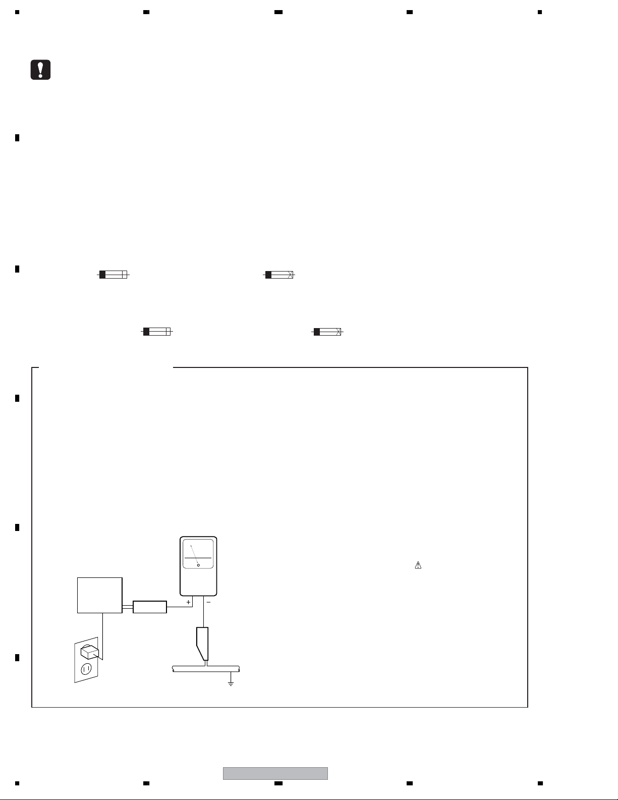
1. SAFETY PRECAUTIONS
The following check should be performed for the
continued protection of the customer and service
technician.
LEAKAGE CURRENT CHECK
Measure leakage current to a known earth ground
(water pipe, conduit, etc.) by connecting a leakage
current tester such as Simpson Model 229-2 or
D
equivalent between the earth ground and all exposed
metal parts of the appliance (input/output terminals,
screwheads, metal overlays, control shaft, etc.). Plug
the AC line cord of the appliance directly into a 120V
AC 60 Hz outlet and turn the AC power switch on. Any
current measured must not exceed 0.5 mA.
Leakage
current
E
Device
under
test
Also test with
plug reversed
(Using AC adapter
plug as required)
Test all
exposed metal
surfaces
AC Leakage Test
tester
Reading should
not be above
0.5 mA
Earth
ground
ANY MEASUREMENTS NOT WITHIN THE
LIMITS OUTLINED ABOVE ARE INDICATIVE
OF A POTENTIAL SHOCK HAZARD AND
MUST BE CORRECTED BEFORE RETURNING THE APPLIANCE TO THE CUSTOMER.
2. PRODUCT SAFETY NOTICE
Many electrical and mechanical parts in the appliance
have special safety related characteristics. These are
often not evident from visual inspection nor the
protection afforded by them necessarily can be obtained
by using replacement components rated for voltage,
wattage, etc. Replacement parts which have these
special safety characteristics are identified in this
Service Manual.
Electrical components having such features are
identified by marking with a
on the parts list in this Service Manual.
The use of a substitute replacement component which
does not have the same safety characteristics as the
PIONEER recommended replacement one, shown in the
parts list in this Service Manual, may create shock, fire,
or other hazards.
Product Safety is continuously under review and new
instructions are issued from time to time. For the latest
information, always consult the current PIONEER
Service Manual. A subscription to, or additional copies
of, PIONEER Service Manual may be obtained at a
nominal charge from PIONEER.
on the schematics and
F
2
1234
A-A9-J
Page 3
5678
A
B
C
D
E
56
A-A9-J
F
3
7
8
Page 4
1234
[Important Check Points for Good Servicing]
In this manual, procedures that must be performed during repairs are marked with the below symbol.
Please be sure to confirm and follow these procedures.
A
1. Product safety
Please conform to product regulations (such as safety and radiation regulations), and maintain a safe servicing environment by
following the safety instructions described in this manual.
1 Use specified parts for repair.
Use genuine parts. Be sure to use important parts for safety.
2 Do not perform modifications without proper instructions.
Please follow the specified safety methods when modification(addition/change of parts) is required due to interferences such as
radio/TV interference and foreign noise.
B
C
D
3 Make sure the soldering of repaired locations is properly performed.
When you solder while repairing, please be sure that there are no cold solder and other debris.
Soldering should be finished with the proper quantity. (Refer to the example)
4 Make sure the screws are tightly fastened.
Please be sure that all screws are fastened, and that there are no loose screws.
5 Make sure each connectors are correctly inserted.
Please be sure that all connectors are inserted, and that there are no imperfect insertion.
6 Make sure the wiring cables are set to their original state.
Please replace the wiring and cables to the original state after repairs.
In addition, be sure that there are no pinched wires, etc.
7 Make sure screws and soldering scraps do not remain inside the product.
Please check that neither solder debris nor screws remain inside the product.
8 There should be no semi-broken wires, scratches, melting, etc. on the coating of the power cord.
Damaged power cords may lead to fire accidents, so please be sure that there are no damages.
If you find a damaged power cord, please exchange it with a suitable one.
9 There should be no spark traces or similar marks on the power plug.
When spark traces or similar marks are found on the power supply plug, please check the connection and advise on secure
connections and suitable usage. Please exchange the power cord if necessary.
0 Safe environment should be secured during servicing.
When you perform repairs, please pay attention to static electricity, furniture, household articles, etc. in order to prevent injuries.
Please pay attention to your surroundings and repair safely.
2. Adjustments
To keep the original performance of the products, optimum adjustments and confirmation of characteristics within specification.
Adjustments should be performed in accordance with the procedures/instructions described in this manual.
3. Lubricants, Glues, and Replacement parts
Use grease and adhesives that are equal to the specified substance.
E
Make sure the proper amount is applied.
4. Cleaning
For parts that require cleaning, such as optical pickups, tape deck heads, lenses and mirrors used in projection monitors, proper
cleaning should be performed to restore their performances.
5. Shipping mode and Shipping screws
To protect products from damages or failures during transit, the shipping mode should be set or the shipping screws should be
installed before shipment. Please be sure to follow this method especially if it is specified in this manual.
F
4
1234
A-A9-J
Page 5

5678
CONTENTS
1. SPECIFICATIONS.............................................................................................................................................6
2. EXPLODED VIEWS AND PARTS LIST .............................................................................................................7
2.1 A-A9 model.................................................................................................................................................7
2.1.1 PACKING (A-A9) ..................................................................................................................................7
2.1.2 EXTERIOR (A-A9)................................................................................................................................8
2.2 A-A6 model...............................................................................................................................................11
2.2.1 PACKING (A-A6) ................................................................................................................................11
2.2.2 EXTERIOR (A-A6)..............................................................................................................................12
3. BLOCK DIAGRA AND SCHEMATIC DIAGRAM .............................................................................................16
3.1 OVERALL BLOCK DIAGRAM ..................................................................................................................16
3.2 OVERALL WIRING DIAGRAM .................................................................................................................18
3.3 FUNCTION and HEADPHONE ASSYS ...................................................................................................20
3.4 FRONT, MOTOR VR, REMOCON, STATION, POWER LED and VR ASSYS ..........................................22
3.5 XM-READY/USB ASSY ............................................................................................................................24
3.6 AMP LCH, AMP RCH, PROTECTION L-CH and PROTECTION R-CH ASSYS......................................26
3.7 REG IC, SUB TRANS, POWER SW and POWER ASSYS ......................................................................28
4. PCB CONNECTION DIAGRAM ......................................................................................................................30
4.1 SUB TRANS and POWER SW ASSYS....................................................................................................31
4.2 FANCTION and HEADPHONE ASSYS....................................................................................................32
4.3 FRONT, REMOCON, POWER LED and VR ASSYS................................................................................34
4.4 STATION and MOTOR VR ASSYS...........................................................................................................36
4.5 XM-READY/USB ASSY ............................................................................................................................38
4.6 AMP LCH, PROTECTION L-CH and SPEAKER L-CH ASSY..................................................................40
4.7 AMP RCH, PROTECTION R-CH and SPEAKER R-CH ASSY................................................................42
4.8 REG IC and POWER ASSYS...................................................................................................................44
5. PCB PARTS LIST............................................................................................................................................46
6. ADJUSTMENT ................................................................................................................................................54
7. GENERAL INFORMATION .............................................................................................................................55
7.1 TROUBLE SHOOTIG................................................................................................................................55
7.2 SPECIFICATION OF PROTECTIVE OPERATION ...................................................................................56
7.3 DISCHARGE OF POWER AMPLIFIER....................................................................................................56
7.4 PCB LOCATION .......................................................................................................................................57
7.5 DISASSEMBLY.........................................................................................................................................58
7.6 IC INFORMATION ....................................................................................................................................62
8. PANEL FACILITIES.........................................................................................................................................66
A
B
C
D
56
A-A9-J
E
F
5
7
8
Page 6
1234
1. SPECIFICATIONS
Amplifier section
Power output specification is for when power supply is 230V.
A
Continuous power output
(both channels driven at 20 Hz to 20 kHz)
THD 0.2%................................................................60 W + 60 W
THD 0.2%................................................................45 W + 45 W
THD 0.2%................................................................70 W + 70 W
THD 0.2%................................................................55 W + 55 W
DIN Continuous power output (both channels driven at 1 kHz)
THD 1.0%, 4Ω.........................................................60 W + 60 W
THD 1.0%, 8Ω.........................................................45 W + 45 W
THD 1.0%, 4Ω.........................................................73 W + 73 W
THD 1.0%, 8Ω.........................................................53 W + 53 W
B
Total harmonic distortion**
20 Hz to 20 kHz, 25 W, 8Ω.................................................0.05%*
* Measured with DIRECT button switched on.
** Measured by Audio Spectrum Analyzer
Audio section
Input (Sensitivity/Impedance)
CD, TAPE, TUNER, AUX.......................................200 mV/47 kΩ
PHONO (MM).........................................................2.8 mV/47 kΩ
PHONO (MC).........................................................0.3 mV/100 kΩ
Frequency Response
CD, TAPE, TUNER, AUX..........................5 Hz to 100 kHz dB
PHONO (MM)......................................20 Hz to 20 kHz ± 0.2 dB
C
PHONO (MC)......................................20 Hz to 20 kHz ± 0.3 dB
PHONO (MM) overload level
1 kHz, THD 0.2%...............................................................60 mV
+0
-3
: A6 model
: A6 model
: A9 model
: A9 model
: A6 model
: A6 model
: A9 model
: A9 model
: A9 model
: A9 model
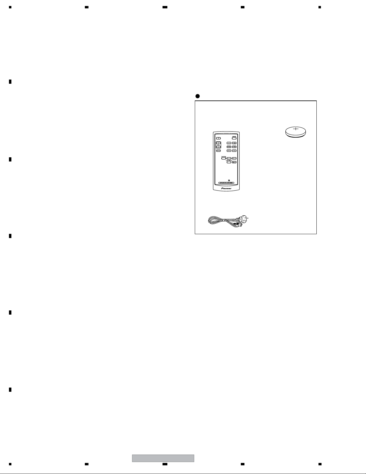
Furnished parts
Remote control................................................................... 1
Lithium battery (CR2025)................................................... 1
Power cable........................................................................ 1
Warranty card.....................................................................1
Operating instructions........................................................ 1
Specifications and the design are subject to possible
modifications without notice, due to improvements.
Accessories
• Remote Control Unit
(A-A9-J : 8300746900010-IL)
(A-A6-J : 8300747200010-IL)
• Power Cable
(L068250160020-IL)
• Lithium Battery
(CR2025)
>
PHONO (MC) overload level
1 kHz, THD 0.2%................................................................6 mV
Output (Level/Impedance)
TAPE REC.................................................................200 mV/1 kΩ
Tone Control
Bass................................................................ ±10 dB (100 Hz)
D
Treble................................................................... ±10 dB (10 kHz)
Signal-to-Noise Ratio
CD, TAPE, TUNER, AUX (200 mV input)............................103 dB
PHONO (MM, 5 mV input)...................................................80 dB
PHONO (MC, 0.2 mV input)..............................................70 dB
Signal-to-Noise Ratio (DIN, continuous power/50 mW)
CD, TAPE, TUNER, AUX..........................................91 dB/65 dB
PHONO (MM, 5 mV input).........................................68 dB/60 dB
PHONO (MC, 0.2 mV input).......................................62 dB/57 dB
Miscellaneous
E
Power requirement
....................................................AC 220 V to 230 V, 50 Hz/60 Hz
Power Consumption..............................................................140 W
In standby..............................................................................0.5 W
Power Consumption..............................................................200 W
In standby.............................................................................0.6 W
Weight (without package)........................................................10 kg
Weight (without package).......................................................1.5 kg
Dimensions......................420 mm (W) × 100 mm (H) × 359 mm (D)
Dimensions......................420 mm (W) × 100 mm (H) × 369 mm (D)
: A9 model
: A9 model
: A9 model
: A6 model
: A6 model
: A9 model
: A9 model
: A6model
: A9 model
: A6 model
: A9 model
F
6
1234
A-A9-J
Page 7
>
5678
2. EXPLODED VIEWS AND PARTS LIST
NOTES:
Parts marked by "NSP" are generally unavailable because they are not in our Master Spare Parts List.
The mark found on some component parts indicates the importance of the safety factor of the part.
Therefore, when replacing, be sure to use parts of identical designation.
Screws adjacent to mark on product are used for disassembly.
For the applying amount of lubricants or glue, follow the instructions in this manual.
(In the case of no amount instructions, apply as you think it appropriate.)
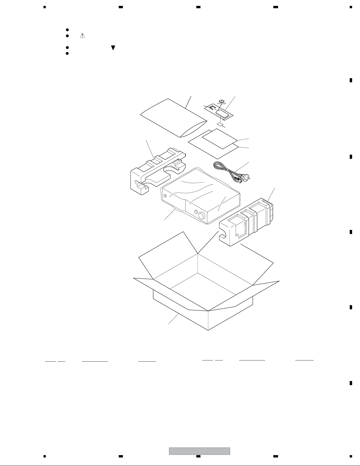
2.1 A-A9 model
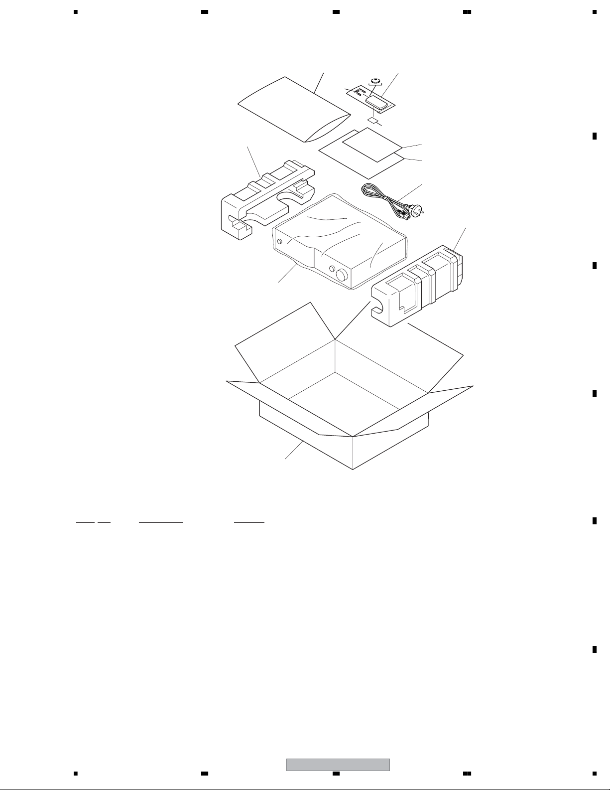
2.1.1 PACKING (A-A9)
A
Lithium
>
6
3
battery
10
2
B
11
9
5
1
4
C
7
8
PACKING (A-A9)
No. Description Part No.
Mark
1POWER CABLE L068250160020-IL
2 REMOTE CONTROL 8300746900010-IL
3 CUSHION,SNOW L 6230211534000-IL
4 CUSHION,SNOW R 6230211544000-IL
5 OPERATING INSTRUCTIONS 5707000000170-IL
(English/French/German/Dutch/Italian/Spanish)
No. Description Part No.
Mark
10 BATTERY COVER B AZN8024
11 LABEL (WEEE) ARW7322
D
E
NSP 6 POLY BAG 6337000240010-IL
7 PE,SHEET 6327040022012-IL
8BOX,GIFT 6007210940010-IL
NSP 9 WARRANTY CARD ARY7065
56
A-A9-J
F
7
7
8
Page 8
1234
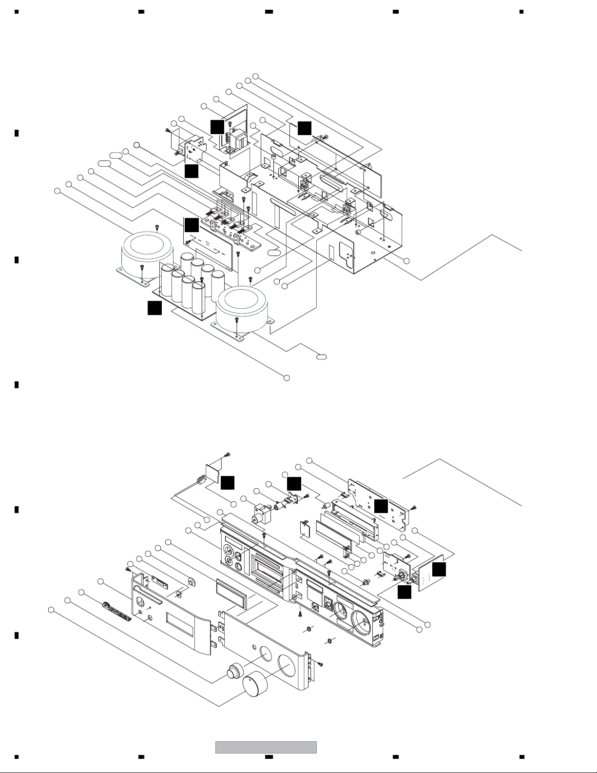
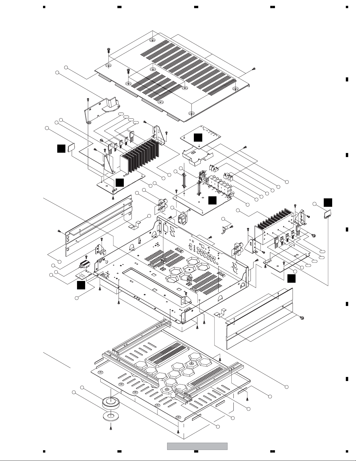
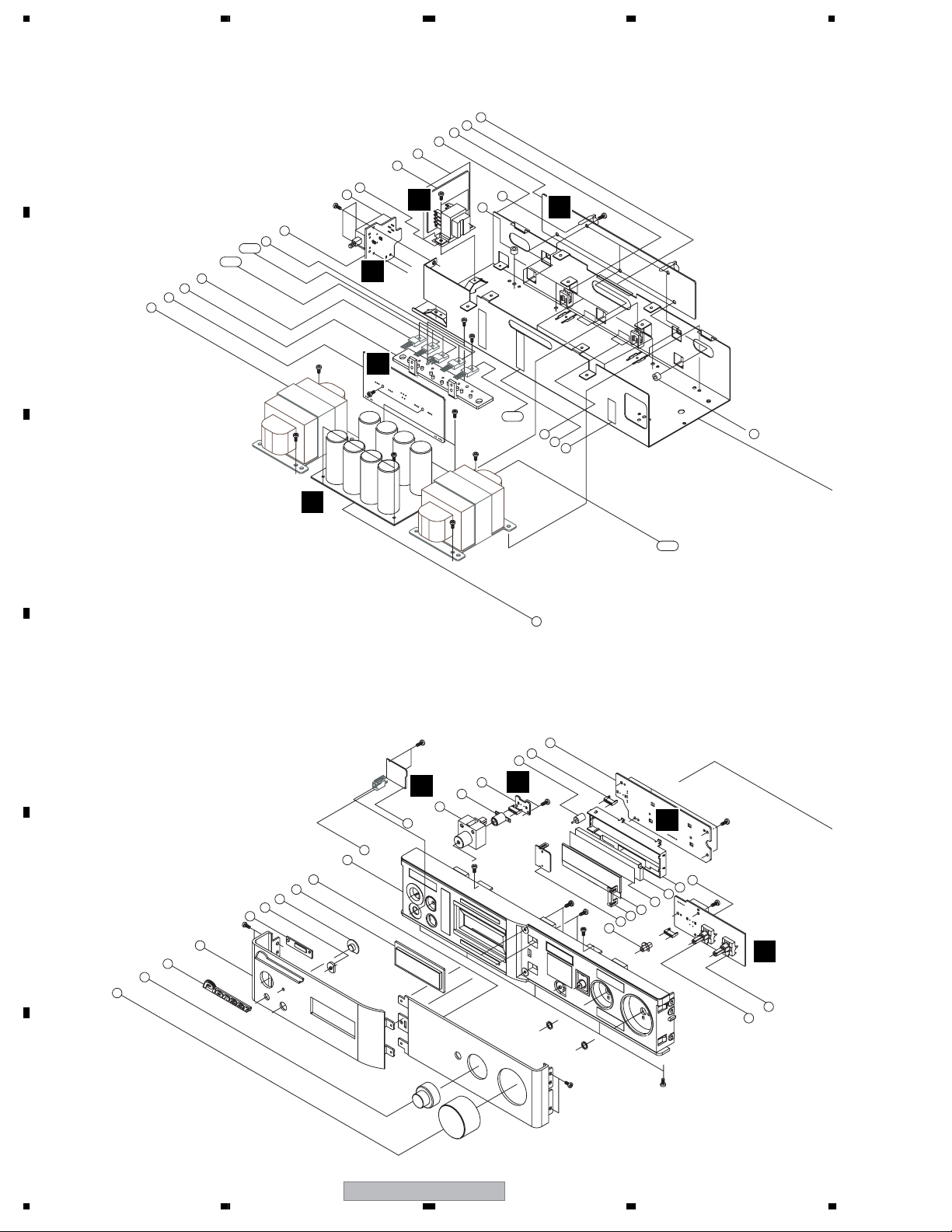
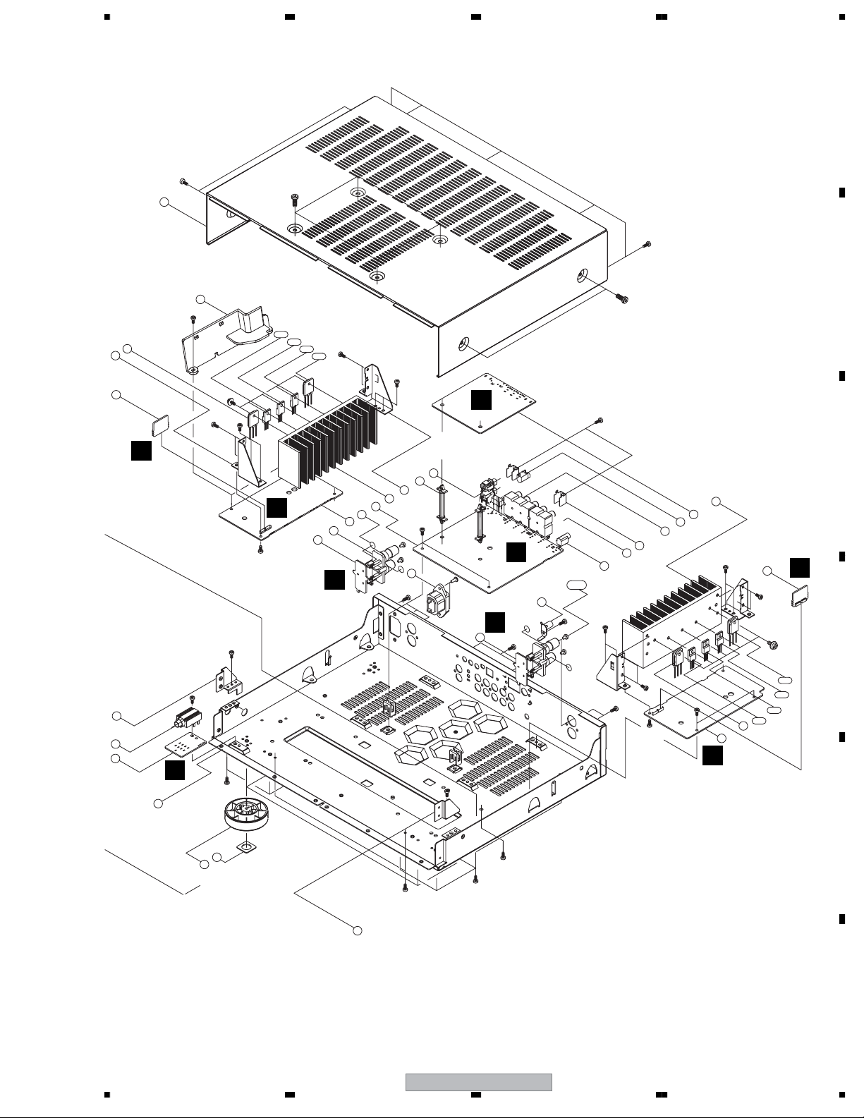
2.1.2 EXTERIOR (A-A9)
A
9
8
7
6
S12*3
5
4
4-2
4-1
4
3
2
B
1
S11
S13*2
S11
L
M
K
S12*2
N
C
10
76
S11*2
S3*2
S11
S11
11
S11*2
88
80
S13*5
87
89
E
S12*5
4-3
85
86
80
• A-A9 model
1-1
32
D
S13*2
D
75
25
74
81
24
23
22
21
20
19
E
16
15
S11*2
18
17
28
27
26
S12
31
30
29
F
S13*2
S10*2
S10*2
S12
B
51
50
49
48
47
46
S13*4
55
54
53
52
S13*3
C
G
S9*1
68
82
S11*2
F
8
A-A9-J
1234
Page 9
5678
S7*4
A
S8*4
14
78
S7*4
S8*4
S15*3
S12*2
13-1
13-2
S11*2
13
12
90
S2*5
P
S14*2
S11*2
S12*2
S7*2
S8*2
S11
13-3
13-4
S14*2
H
S15*2
45
44
43
42
I
38
41
40
39
77
S15*2
S3*2
73
S9*2
A
61
60
59
58
83
56
S14*2
S15
S15*7
79
63
62
S14*2
91
Q
S11*2
S2*5
B
C
S11*2
37
36
35
34
S12
S15*2
S12*2
S12*2
13
92
13-4
13-3
13-2
13-1
D
J
O
33
S5*4
S11*2
67
66
S6*4
S4*5
S11
S5*4
S11
S7*2
S8*2
E
S1*2
72
S11*9
71
70
69
84
F
56
A-A9-J
9
7
8
Page 10

1234
• EXTERIOR (A-A9)
No. Description Part No.
Mark
1POWER TRANS L 8200900550010-IL
1-1 POWER TRANS R 8200900550060-IL
A
2 REG IC Assy 7028065471020-IL
3 HEAT SINK TR 2120211008000-IL
4IC,REG J126781200040-IL
4-1 IC,REG J126791200060-IL
5POWER SW Assy 7028065357060-IL
6 S/W POWER VSA1005
7 TRANS SUB 8200280150330-IL
8 SUB TRANS Assy 702806535A060-IL
9 PLATE SUB TRANS 4470211012000-IL
10 BRACKER TRANS 4010212736000-IL
11 SUPPORT PCB 4070001601010-IL
B
12 BRACKER HEAT SINK L 4010212716000-IL
>
13 SEMI,TR J5001386A0010-IL
>
13-1 SEMI,TR 2SA1859A
>
13-2 SEMI,TR J5024137V0130-IL
>
13-3 SEMI,TR ASC4883A
>
13-4 SEMI,TR J5023519A0010-IL
14 CABINET TOP COVER 3007210786000-IL
15 KNOB VOLUME 5088211378000-IL
16 KNOB INPUT 5088211368000-IL
17 BADGE VAM1124
18 PANEL FRONT L 3067212778000-IL
C
19 GUIDE BADGE 4357210221000-IL
20 GUIDE LENS 4357210241000-IL
21 LENS REMOCON 3710210683000-IL
22 WINDOW DISPLAY 5070212303000-IL
23 PANEL FRONT R 3067212798000-IL
24 FRAME PANEL 3217211301000-IL
25 PLATE TOP 4477211028000-IL
26 KNOB POWER 5087211391000-IL
27 LENS POWER 3710210673000-IL
28 POWER LED Assy 7028065358060-IL
29 LENS STAND BY 3710210693000-IL
D
30 STOPPER LED 4380210081000-IL
31 FRONT Assy 7028065354060-IL
32 POWER Assy 7025065353060-IL
NSP 33 CHASSIS MAIN & BACK 3207212016200-IL
34 HEADPHONE Assy 702806535B060-IL
35 JACK PHONE G402PJ612AG0Y-IL
36 BRACKET FRAEM L 4010212696000-IL
37 PANEL SIDE 3067212818000-IL
38 TER,BOARD SCREW(BK) G610040300000-IL
39 TER,BOARD SCREW(RD) G610040310000-IL
E
40 AMP LCH Assy 7028065351010-IL
41 FUNCTION Assy 7028065361060-IL
NSP 42 HEAT SINK MAIN L 2120210998000-IL
43 BRACKER HEAT SINK R 4010212726000-IL
44 SPACER SUPPORT 4300210023000-IL
45 JACK RCA 2PIN 7028065355060-IL
46 LENS DIRECTY 3710210663000-IL
47 COVER LCD L 4310212951000-IL
48 COVER LCD R 4310212961000-IL
49 LCD DISPLAY AAV7111
50 SHEET LCD DIFFUSION 1210210382000-IL
F
51 WINDOW RAT LCD 5070212313000-IL
52 HOUSING LCD 3050210051000-IL
53 VR Assy 7028065359060-IL
54 ROTARY MOTOR C495121400350-IL
10
1234
>
>
No. Description Part No.
Mark
55 MOTOR VR Assy 7028065355060-IL
56 TERMINAL GROUND 3790000090000-IL
59 JACK RCA 6PIN G603617AG04GY-IL
60 SHIELD PLATE GROUND 3070045526010-IL
61 CN,PLUG CONTACT G480670680010-IL
62 EARPHONE JACK G40130802000Y-IL
63 XM-READY/USB Assy 7028065362060-IL
66 FELT FOOT CAST 2690210119000-IL
67 FOOT CAST 4007210408000-IL
68 ENCODER SW G121162400050-IL
69 BAR BOTTOM FRONT 1040000018000-IL
70 COVER BOTTOM 4317212946000-IL
71 BAR BOTTOM SIDE 1040000028000-IL
72 BRACKET FRAME R 4010212706000-IL
73 AC INLET G430019090010-IL
74 MODULE E940633800000-IL
75 REMOCON Assy 7028065356060-IL
76 STATION Assy 7028065461020-IL
77 HOLDER CHIP 4320210591000-IL
78 HOLDER INLET CORD 4320210601000-IL
79 SHIELD PLATE USB 3070210286000-IL
80 CUSHION SCREW 4050211205000-IL
NSP 81 TAPE PLATE TOP(E) 1220210299000-IL
NSP 82 TAPE PLATE TOP(F) 1220210309000-IL
NSP 83 HEAT SINK MAIN R 2120211048000-IL
84 CUSHION SIDE PANEL 4050211725000-IL
NSP 85 ACETAPE(15*80) 1220210059070-IL
NSP 86 ACETAPE(15*45) 1220210059050-IL
NSP 87 ACETAPE(33*50) 1220210319000-IL
NSP 88 ACETAPE(15*110) 1220210059000-IL
89 BAR BOTTOM FRONT 4330210062000-IL
90 PROTECTION L-CH ASSY 7028065363010-IL
91 PROTECTION R-CH ASSY 7028065364010-IL
92 AMP RCH ASSY 7028065352010-IL
S1 SCREW B020030083B10-IL
(+2S 3*8 B-TYPE BK/BH)
S2 SCREW B018230141H11-IL
(+2S 3*14 P+S-WASHER ZNY/HH )
S3 SCREW B020030171B10-IL
(+2S 3*17 B-TYPE ZNY/BH)
S4 SCREW B020030173B10-IL
(+2S 3*17 B-TYPE BK/BH)
S5 SCREW (+2S 4*10 ZNY/HH) B028940101B10-IL
S6 SCREW B020740273B10-IL
(+3S 4*27 S-TYPE BK/BH)
S7 SCREW 1500040103P41-IL
(+2S 4*10 B-TYPE CR-PLATE)
S9 SCREW B020030086F10-IL
(+2S 3*8 B-TYPE FH/CU)
S10 SCREW B020030106B10-IL
(+2S 3*10 B-TYPE BH/CU)
S11 SCREW B020030086B11-IL
(+2S 3*8 B-TYPE(DOT) BH/CU)
S12 SCREW B028030086B10-IL
(+2S 3*8 B-TYPE WASHER BH/CU)
S13 SCREW B020030086B10-IL
(+2S 3*8 B-TYPE BH/CU)
S14 SCREW B020030066B10-IL
(+2S 3*6 B-TYPE BH/CU)
S15 SCREW B020030106B11-IL
(+3S 3*10 B-T(DOT) BH/CU))
A-A9-J
Page 11
5678
2.2 A-A6 model
2.2.1 PACKING (A-A6)
>
Lithium
>
6
3
7
battery
10
11
2
9
5
1
4
A
B
8
• PACKING (A-A6)
No. Description Part No.
Mark
1POWER CABLE L068250160020-IL
2 REMOTE CONTROL 8300747200010-IL
3 CUSHION,SNOW L 6230211514000-IL
4 CUSHION,SNOW R 6230211524000-IL
5 OPERATING INSTRUCTIONS 5707000000120-IL
(English/French/German/Dutch/Italian/Spanish)
NSP 6 POLY BAG 6337000240010-IL
7 PE,SHEET 6327040022012-IL
8BOX,GIFT 6007210930010-IL
NSP 9 WARRANTY CARD ARY7065
10 BATTERY COVER B AZN8024
11 LABEL (WEEE) ARW7322
C
D
E
56
A-A9-J
F
11
7
8
Page 12
1234
2.2.2 EXTERIOR (A-A6)
A
B
C
• A-A6 model
2
1
76
11
70
10
9
8
7
6
S10*3
5
4
4-2
4-1
4
3
S9
M
S9
K
S11*2
S10*2
L
S9*2
S9*2
S2*2
S9
72
S11*5
77
4-3
S10*5
E
75
73
74
72
N
S9
1-1
31
D
F
30
29
28
S11*2
S8*2
S8*2
S10
B
49
48
47
46
45
44
S11*4
51
50
S11*3
G
62
63
S11*2
D
67
66
24
23
22
21
E
16
15
S9*2
18
17
20
19
27
26
25
S10
S9*2
S7*6
F
12
A-A9-J
1234
Page 13
5678
A
S4*2
S5*2
14
S4*4
S5*4
S13*5
71
S10*2
13-1
13-2
13
12
80
S1*5
S12*2
S9*2
S9*2
13-3
13-4
S12*2
H
S4*2
S5*2
S13*2
B
P
43
42
41
40
I
36
S10*2
R
S9
S10
35
34
33
39
78
38
37
S2*2
S13*3
59
58
S12*2
56
S13*3
57
S9*2
S10*2
S10*2
A
65
S7*2
S
83
S13*8
37-1
54
S13
79
61
60
S12*2
82
81
Q
S9*2
S1*5
13-4
13-3
13-2
13-1
13
J
C
D
O
32
S3*4
S9
53
52
S9*2
64
S9
S3*4
A-A9-J
56
E
F
13
7
8
Page 14

1234
• EXTERIOR (A-A6)
No. Description Part No.
Mark
1 TRANS MAIN L 8200660550340-IL
1-1 TRANS MAIN R 8200660550390-IL
A
2 REG IC Assy 7028065471010-IL
3 HEAT SINK TR 2120211008000-IL
4IC,REG J126781200040-IL
>
>
>
>
>
>
>
No. Description Part No.
Mark
49 WINDOW RAT LCD 5070212313000-IL
50 HOUSING LCD 3050210051000-IL
51 VR Assy 7028065359010-IL
52 FOOT 4000210391000-IL
53 CUSHION FOOT 4050211605000-IL
4-1 IC,REG J126791200060-IL
5POWER SW Assy 7028065357010-IL
6 S/W POWER VSA1005
7 TRANS SUB 8200280150330-IL
8 SUB TRANS Assy 702806535A010-IL
9 PLATE SUB TRANS 4470211012000-IL
10 BRACKER TRANS 4010212736000-IL
B
11 SUPPORT PCB 4070001601010-IL
12 BRACKER HEAT SINK L 4010212716000-IL
13 SEMI,TR J5001386A0010-IL
13-1 SEMI,TR 2SA1859A
13-2 SEMI,TR J5024137V0130-IL
13-3 SEMI,TR 2SC4883A
13-4 SEMI,TR J5023519A0010-IL
14 CABINET TOP COVER 3007210796000-IL
15 KNOB VOLUME 5088211388000-IL
16 KNOB INPUT 5088211368000-IL
C
17 BADGE VAM1124
18 PANEL FRONT L 3067212788000-IL
19 GUIDE BADGE 4357210221000-IL
20 GUIDE LENS 4357210241000-IL
21 LENS REMOCON 3710210683000-IL
22 WINDOW DISPLAY 5070212303000-IL
23 PANEL FRONT R 3067212808000-IL
24 FRAME PANEL 3217211311000-IL
54 TERMINAL GROUND 3790000090000-IL
57 JACK RCA 6PIN G602617AG020Y-IL
58 SHIELD PLATE GROUND 3070045526010-IL
59 RCA JACK 6PIN G603617AG04GY-IL
60 EARPHONE JACK G40130802000Y-IL
61 XM-READY/USB Assy 7028065362010-IL
62 ENCODER, SW/ VOLUME G121162401200-IL
63 ENCODER, SW/ INPUT G121162400050-IL
64 BRACKET FRAME R 4010212706000-IL
65 AC INLET G430019090010-IL
66 MODULE E940633800000-IL
67 REMOCON Assy 7028065356010-IL
70 STATION Assy 7028065461010-IL
71 HOLDER INLET CORD 4320210601000-IL
72 CUSHION SCREW 4050211205000-IL
NSP 73 ACETAPE(15*80) 1220210059070-IL
NSP 74 ACETAPE(15*45) 1220210059050-IL
NSP 75 ACETAPE(33*50) 1220210319000-IL
NSP 76 ACETAPE(15*110) 1220210059000-IL
77 CLAMP RETAINER COIL 4330210062000-IL
NSP 78 CUSHION CAP SCREW 4050211745000-IL
NSP 79 HEAT SINK MAIN R 2120211048000-IL
80 PROTECTION L-CH ASSY 7028065363010-IL
81 PROTECTION R-CH ASSY 7028065364010-IL
82 AMP RCH ASSY 7028065352010-IL
25 KNOB POWER 5087211391000-IL
26 LENS POWER 3710210673000-IL
D
27 POWER LED Assy 7028065358010-IL
28 LENS STAND BY 3710210693000-IL
29 STOPPER LED 4380210081000-IL
30 FRONT Assy 7028065354010-IL
31 POWER Assy 7025065353010-IL
NSP 32 CHASSIS MAIN & BACK 3207212016000-IL
33 HEADPHONE Assy 702806535B060-IL
34 JACK PHONE G402PJ612AG0Y-IL
35 BRACKET FRAEM L 4010212696000-IL
36 SPAKER L-CH Assy 7028065462010-IL
E
37 JACK SPEAKER G611202H0100Y-IL
37-1 BUSHING TREMINAL 2410040353010-IL
38 AMP LCH Assy 7028065351010-IL
39 FUNCTION Assy 7028065361010-IL
NSP 40 HEAT SINK MAIN L Assy 2120210998000-IL
41 BRACKER HEAT SINK R 4010212726000-IL
42 SPACER SUPPORT 4300210023000-IL
43 JACK RCA 2PIN G601207BG020Y-IL
44 LENS DIRECT 3710210663000-IL
45 COVER LCD L 4310212951000-IL
F
46 COVER LCD R 4310212961000-IL
47 LCD DISPLAY AAV7111
48 SHEET LCD DIFFUSION 1210210382000-IL
83 SPAKER R-CH Assy 7028065463010-IL
S1 SCREW B020030083B10-IL
(+2S 3*8 B-TYPE BK/BH)
S2 SCREW B018230141H11-IL
(+2S 3*14 P+S-WASHER ZNY/HH)
S3 SCREW B020030171B10-IL
(+2S 4*10 ZNY/HH)
S4 SCREW B020030173B10-IL
(1500040103P41S)
S5 SCREW B028940101B10-IL
(1500040104P41S)
S6 SCREW B020740273B10-IL
(+3S 4*17 S-TYPE BK/BH)
S7 SCREW B020030086F10-IL
(+2S 3*8 B-TYPE FH/CU)
S8 SCREW B020030106B10-IL
(+2S 3*10 B-TYPE BH/CU)
S9 SCREW B020030086B11-IL
(+2S 3*8 B-TYPE(DOT) BH/CU)
S10 SCREW B028030086B10-IL
(+2S 3*8 B-TYPE WASHER BH/CU)
S11 SCREW B020030086B10-IL
(+2S 3*8 B-TYPE BH/CU)
S12 SCREW B020030066B10-IL
(+2S 3*6 B-TYPE BH/CU)
S13 SCREW B020030106B11-IL
(+3S 3*10 B-T(DOT) BH/CU))
14
A-A9-J
1234
Page 15

5678
A
B
C
D
E
56
A-A9-J
F
15
7
8
Page 16
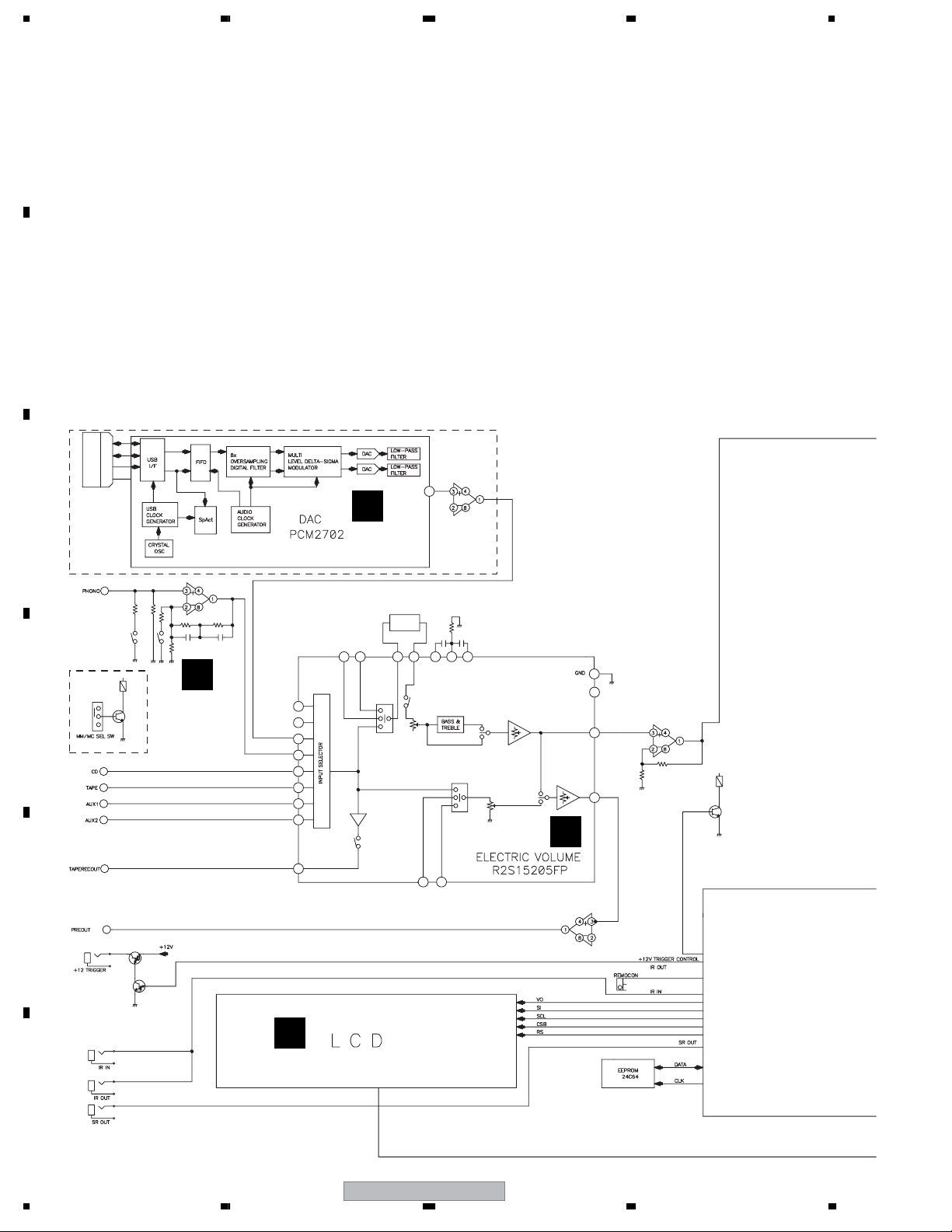
1234
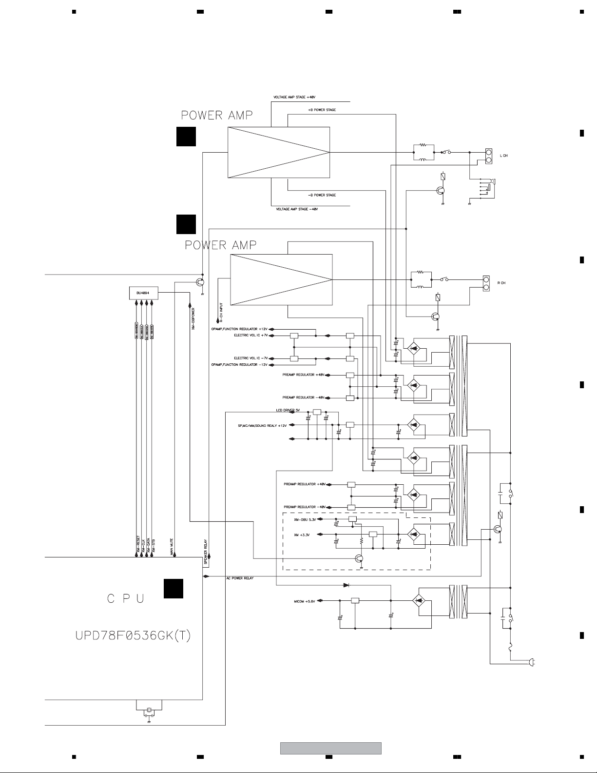
3. BLOCK DIAGRA AND SCHEMATIC DIAGRAM
3.1 OVERALL BLOCK DIAGRAM
A
B
IC513
C
A-A9 TYPE ONLY
IC108
IC510
A
D
A-A9 TYPE ONLY
E
60
56
54
48
52
50
66
H
A-A9 only
Sound Retriever
(Analogue)
IC104, IC105
362334
IC101
A
IC106
FLAT AMP
A-A9 : 8.8 dB
A-A6 : 7.7 dB
17
7
V601
B
IC109
F
16
1234
A-A9-J
Page 17
5678
A
I
J
IC111
IC112
IC804
IC801
IC802
IC805
RY701
B
RY702
C
IC102
A
IC809
IC806
D
IC808
E
F
56
A-A9-J
17
7
8
Page 18
1234
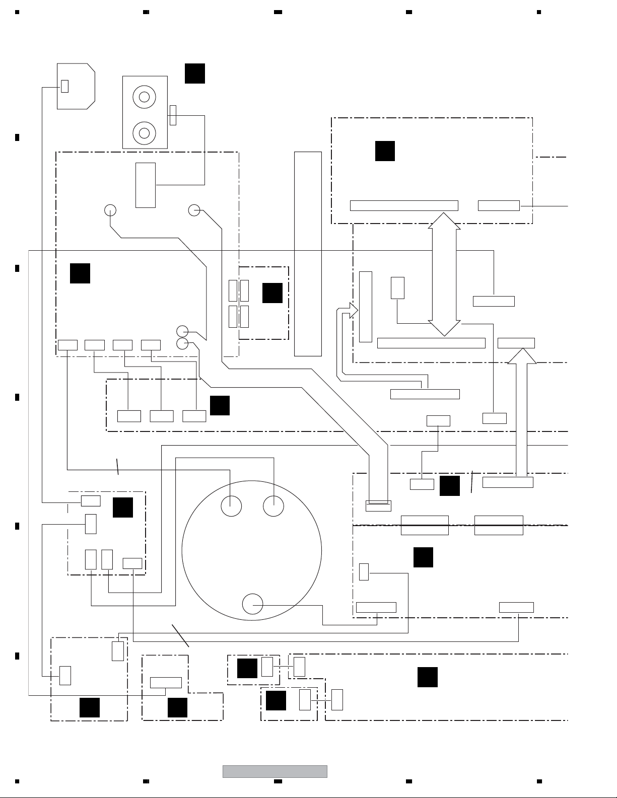
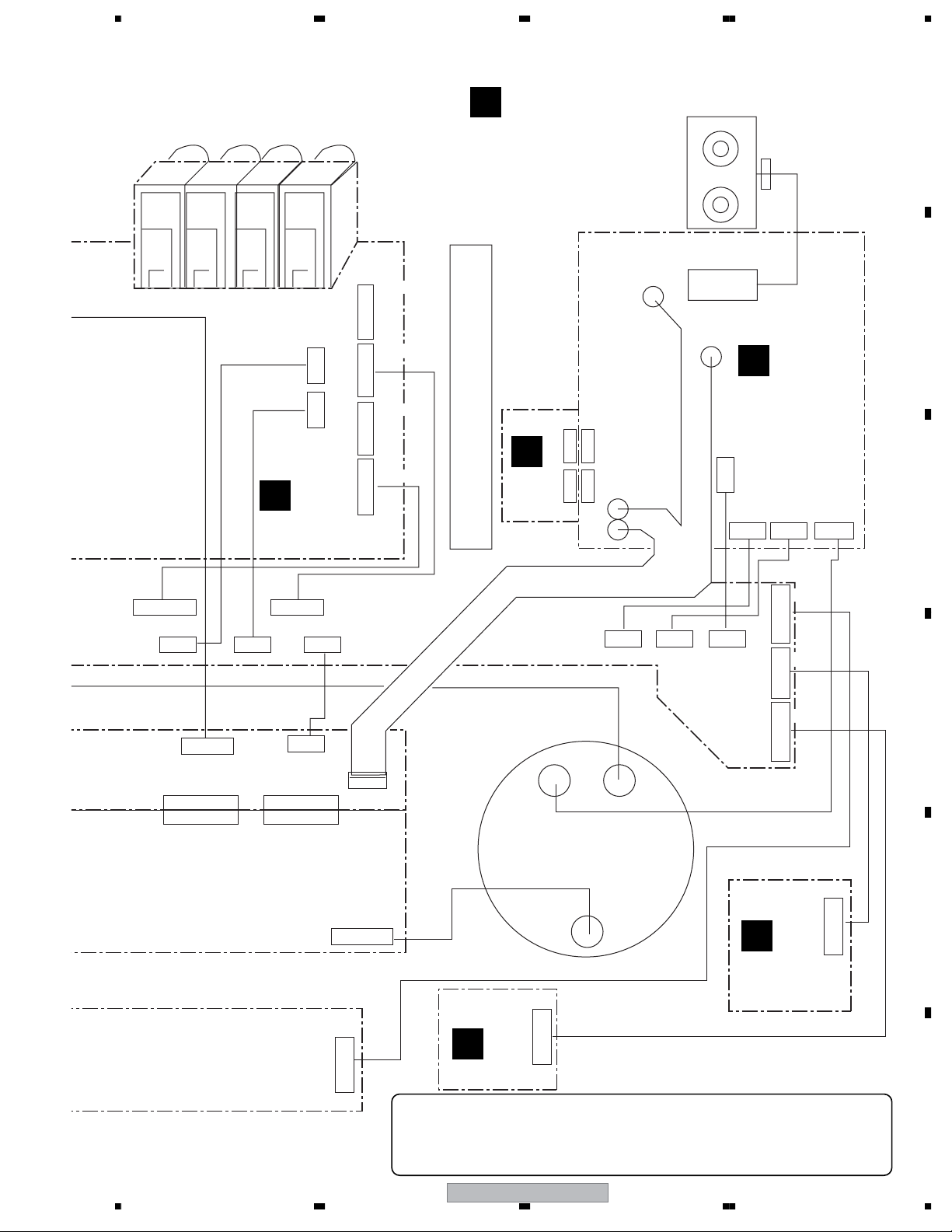
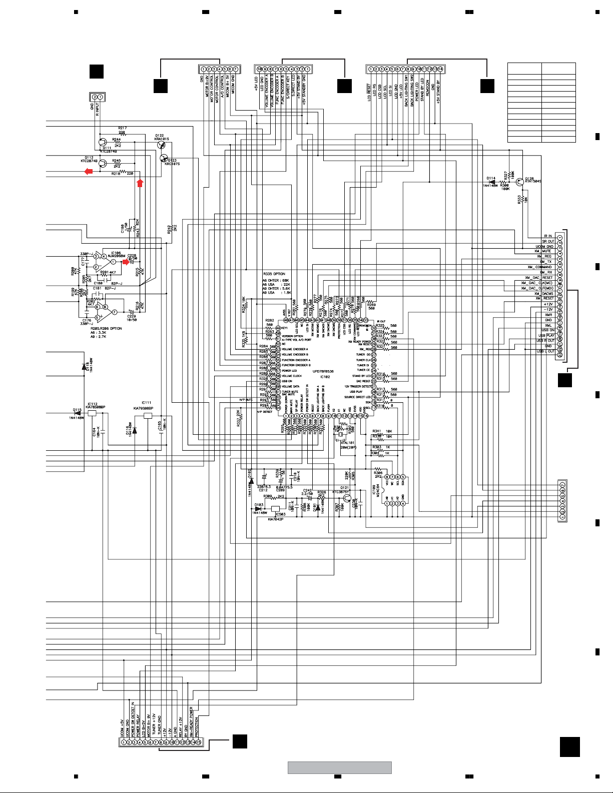
3.2 OVERALL WIRING DIAGRAM
A
JA701 (A-A6)
SPEAKER L-CH ASSY
R
(A-A6:7028065462010-IL)
CN911 (A-A6)
2P WIRE
2P INLET
H
CN711
2P WAFER
B
AMP LCH ASSY
(7028065351010-IL)
C
WAFER WAFER WAFERWAFER
CN753 CN705 CP702 CN703
RD WH
I
2P 2P
(7028065363010-IL)
PROTECTION L-CH ASSY
CN771
P
BK
YL
2P3P
CN770
CN752 CN751
HEAT SINK
XM READY/USB ASSY
(A-A9:7028065362060-IL)
(A-A6:7028065362010-IL)
CN501
CN113
CN107
14P WAFER
3P WIRE
23P WAFER
6P WAFER23P WAFER
CN550
23P CARD CABLE
4P WAFER
CN9103
CN102
CN101
14P WAFER
(A-A9:702806535A060-IL)
(A-A6:702806535A010-IL)
D
2P INLET WIRE
3P WAFER
SUB TRANS ASSY
CN301
CN653
E
2P WIRE
4P WIRE
CN709
2P
CN801
M
F
(A-A9:7028065357060-IL)
(A-A6:7028065357010-IL)
18
1234
CN916 CN915 CN914
L
2P
CN802
2P
2P
CN708
CN804
4P
2P WIRE
(A-A9:7028065358060-IL)
(A-A6:7028065358010-IL)
CN651
HEADPHONE ASSYPOWER SW ASSY
(702806535B060-IL)
2P WAFER
2P WIRE
2P WIRE
4P WIRE
POWER LED
ASSY
O
4P WIRE
STATION ASSY
E
(A-A9:7028065461020-IL)
(A-A6:7028065461010-IL)
TRANS L
2P
F
D
REMOCON ASSY
(A-A9:7028065356060-IL)
(A-A6:7028065356010-IL)
A-A9-J
8P WIRE
CN681CN682
2P
CN680
3P
3P
CN680
14P WIRE
CN913
CN9913
2P WAFER 3P WAFER2P WAFER2P WAFER
(A-A9:7028065471020-IL)
(A-A6:7028065471010-IL)
2P WIRE
CN803
K
CN912
REG IC ASSY
CN816
4P WAFER
CN818
2P WAFER
CN803 CN852
CN820 CN819
10P WAFER
CN813
POWER ASSY
N
(A-A9:7028065353060-IL)
(A-A6:7028065353010-IL)
FRONT ASSY
B
(A-A9:7028065354060-IL)
(A-A6:7028065354010-IL)
10P WAFER10P WAFER
10P WAFER
CN811
14P WIRE
CN801
4P WAFER8P WAFER
Page 19
5678
CN104
CN103
2P WIRE
2P WIRE
A
FUNCTION ASSY
(A-A9:7028065361060-IL)
(A-A6:7028065361010-IL)
CN105
CN106
CN111
CN110
10P WAFER 7P WAFER 7P WAFER 11P WAFER
7P WIRE
10P WIRE
SPEAKER R-CH ASSY
S
(A-A6:7028065463010-IL)
(7028065364010-IL)
PROTECTION R-CH ASSY
CN772 CN755
Q
CN754
CN773
HEAT SINK
YL
BK
WH
JA0000 (A-A6)
CN912 (A-A6)
CN712
2P WAFER
RD
J
AMP RCH ASSY
(7028065352010-IL)
CN704
2P
WAFER
WAFER WAFER
2P WIRE
WAFER
CN766CN707CN706
3P2P2P
A
B
C
CN910 CN909
CN908 CN907 CN906
2P WAFER 2P WAFER
10P WAFER
2P WAFER
6P WIRE
CN802CN815
CN818 CP817
10P WAFER10P WAFER
10P WAFER
CN812 CN810
56
2P WIRE
4P WAFER
CN804
6P WAFER
CN608
CN814
14P WAFER
4P WIRE
CN905 CN904 CN903
2P WAFER
2P WAFER 2P WAFER
CN9914
14P WAFER7P WAFER
CN9916
CN9915
10P WAFER
10P WIRE
14P CARD CABLE
TRANS R
CN606
6P WIRE
CN607
G
VR ASSY
÷
When ordering service parts, be sure to refer to "EXPLODED VIEWS and PARTS
LIST" or "PCB PARTS LIST".
÷
The > mark found on some component parts indicates the importance of the safety
factor of the part. Therefore, when replacing, be sure to use parts of identical
designation.
10P WAFER
(A-A9:7028065359060-IL)
(A-A6:7028065359010-IL)
A-A9-J
7
C
7P WAFER
MOTOR
VR ASSY
(A-A9:7028065355060-IL)
8
D
7P CARD CABLE
10P CARD CABLE
E
F
19
Page 20
1234
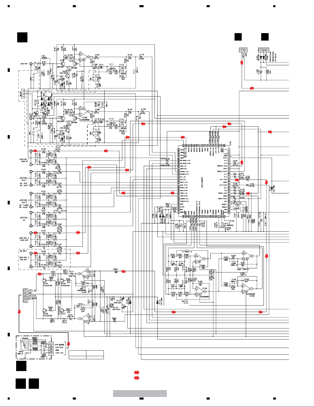
3.3 FUNCTION and HEADPHONE ASSYS
A
FUNCTION ASSY
A
(A-A9:7028065361060-IL) (A-A6:7028065361010-IL)
E
CN908
CN104
(A-A9
only)
B
C
(HP)
E
CN912
CN107
(HP)
D
E
F
(HP)
CN9103
(HP)
HEADPHONE ASSY
O
(702806535B060-IL)
A
O
20
1234
CN651
(A-A9 only)
(HP)
SCHEMATIC
DIAGRAM
JACK601 JA601
PCB PARTS
LIST
(HP)
: AUDIO SIGNAL ROUTE (L ch)
(HP)
: AUDIO SIGNAL ROUTE (H.P L ch)
A-A9-J
(HP)
(A-A9 only)
(HP) (HP)
Page 21
E
CN907
CN103
5678
(A-A9 only)
E
CN909
CN106
CN110
CN910
E
CN113
E
CN911
SCHEMATIC
DIAGRAM
JACK101 JA101
JACK102 JA102
JACK103 JA103
RELAY100 RY100
RELAY101 RY101
SW102
UP101 J101
XTAL101 X101
ZD101 D9101
ZD102 D9102
R214 C214
R215 C215
PCB PARTS
LIST
S102
CN102
A
B
H
CN501
CN111
C
D
E
CN101
CN801
K
A-A9-J
56
F
A
21
7
8
Page 22

1234
3.4 FRONT, MOTOR VR, REMOCON, STATION, POWER LED and VR ASSYS
FRONT ASSY
B
A
B
(A-A9:7028065354060-IL)
(A-A6:7028065354010-IL)
CN681
C
SCHEMATIC
DIAGRAM
LCD601 V601
LED601 D601
LED604 D604
LED605 D605
LED606 D606
J605 R9605
J656 R9656
J658 R9658
J659 R659
J660 R660
D
PCB PARTS
LIST
CN608
CN680
D
REMOCON ASSY
(A-A9:7028065356060-IL)
MOTOR VR ASSY
C
(A-A9:7028065355060-IL)
E
CN606
SCHEMATIC
DIAGRAM
* VR601
PCB PARTS
LIST
(A-A6:7028065356010-IL)
CN680
SCHEMATIC
DIAGRAM
REMO601 601
PCB PARTS
LIST
F
B C D
22
A-A9-J
1234
Page 23

5678
F
POWER LED
ASSY
(A-A9:
7028065358060-IL)
(A-A6:
7028065358010-IL)
STATION ASSY
E
(A-A9:7028065461020-IL)
(A-A6:7028065461010-IL)
A
CN913CN9914
CN113
A
B
SCHEMATIC
DIAGRAM
CN682
LED603 D603
PCB PARTS
LIST
J
J
J
I
I
I
CN9916
CN9915
CN903
CN704
CN904
CN707
CN905
CN706
CN914
CN703
CN915
CP702
CN916
CN705
CN909
CN106
A
CN910
CN110
A
CN906
CN802
A
CN912
CN107
A
CN907
CN103
A
CN9913
CN803
K
CN908
CN104
A
C
D
G
VR ASSY
(A-A9:7028065359060-IL)
(A-A6:7028065359010-IL)
CN607
56
A-A9-J
: AUDIO SIGNAL ROUTE (L ch)
E
SCHEMATIC
DIAGRAM
LED602 D602
SW601 S601
VR602 S602
PCB PARTS
LIST
F
FE G
23
7
8
Page 24

1234
3.5 XM-READY/USB ASSY
XM-READY/USB ASSY
H
A
B
C
(A-A9:7028065362060-IL)
(A-A6:7028065362010-IL)
(A-A9 only)
D
E
F
H
24
1234
SR OUT
A-A9-J
Page 25

5678
A
SCHEMATIC
DIAGRAM
BKT501 501
BKT502 502
JACK503 JA503
JACK504 JA504
XTAL502 X502
ZD501 D501
GND502 502
GND503 503
PCB PARTS
LIST
B
C
D
56
A-A9-J
CN102
A
CN501
E
CN815
K
CN550
F
H
25
7
8
Page 26

1234
3.6 AMP LCH, AMP RCH, PROTECTION L-CH and PROTECTION R-CH ASSYS
AMP L CH ASSY
A
I
(7028065351010-IL)
CN915
Idel Adj
CN713
Idel -TP
E
CN702
DC offset
CN705
CN916
B
NP
L701
CN711
To SP TERMINAL (A-A9)
E
NP
CN911 (A-A6)
CN816
JP0000
R
K
CN703
CN914
C
E
CN753
22/50
CN752
CN751
To. Power trans L
D
E
SCHEMATIC
DIAGRAM
RV701 VR701
RV702 VR702
RELAY701 RY701
ZD701 D9701
ZD702 D9702
ZD703 D9703
ZD704 D9704
LED701 D8701
LED702 D8702
ZD707 D707
ZD708 D708
PCB PARTS
LIST
PROTECTION L-CH ASSY
P
(7028065363010-IL)
: AUDIO SIGNAL ROUTE (L ch)
CN770 CN771
F
I P
26
A-A9-J
1234
Page 27

5678
AMP R CH ASSY
J
(7028065352010-IL)
A
CN905
CN706
E
CN904
CN707
E
JP0000
CN814
K
CN704
CN903
E
CN766
DC offset
Idle Adj
NP
47/10
CN710
Idle -TP
To SP TERMINAL (A-A9)
L702
NP
CN712
B
CN912(A-A6)
S
CN754
CN755
C
To. Power trans R
SCHEMATIC
DIAGRAM
RELAY702 RY702
RV703 VR703
RV704 VR704
ZD706 D706
LED703 D703
ZD705 D705
J716 R9716
J718 R9718
J719 R9719
J720 R9720
J721 R9721
J722 R9722
J729 R9729
J730 R9730
J732 R9732
J735 R9735
J739 R9739
J751 R9751
J752 R9752
J754 R9754
J755 R9755
J756 R9756
J757 R9757
J758 R9758
J759 R9759
J760 R9760
PCB PARTS
LIST
PROTECTION R-CH ASSY
Q
(7028065364010-IL)
D
E
CN773 CN722
F
56
A-A9-J
QJ
27
7
8
Page 28

1234
3.7 REG IC, SUB TRANS, POWER SW and POWER ASSYS
A
REG IC ASSY
K
(A-A9:7028065471020-IL)
(A-A6:7028065471010-IL)
CN816
JP0000
I
A-A9 only
CN550
B
C
H
CN101
A
CN9913
E
CN906
E
CN815
CN801
CN803
CN802
CN817
CN818
CN819
CN820
D
J
CN814
JP0000
SCHEMATIC
DIAGRAM
SW801 S801
POWER SW ASSY
M
PCB PARTS
LIST
(A-A9:7028065357060-IL)
(A-A6:7028065357010-IL)
CN708
CN709
SUB TRANS ASSY
E
L
(A-A9:702806535A060-IL)
(A-A6:702806535A010-IL)
SCHEMATIC
DIAGRAM
RLY651 RY651
* FU0
F
* 0000
PCB PARTS
LIST
CN804
CN801
To. Power trans L
CN802
To. Power trans R
CN653
LIVE
NEUTRAL
CN301
K L M
28
A-A9-J
1234
Page 29

5678
POWER ASSY
N
(A-A9:7028065353060-IL)
A
(A-A6:7028065353010-IL)
CN810
B
CN812
CN803
To. Power trans L
CN811
CN813
A-A9 only
A-A9 only
CN804
To. Power trans R
CN852
CN818
C
D
E
• NOTE FOR FUSE REPLACEMENT
CAUTION -
FOR CONTINUED PROTECTION AGAINST RISK OF FIRE.
REPLACE WITH SAME TYPE AND RATINGS OF FUSE.
56
A-A9-J
SCHEMATIC
DIAGRAM
J811 R811
J812 R9812
J866 R866
J867 R867
PCB PARTS
LIST
F
N
29
7
8
Page 30

1234
4. PCB CONNECTION DIAGRAM
NOTE FOR PCB DIAGRAMS :
1. Part numbers in PCB diagrams match those in the schematic
A
diagrams.
2. A comparison between the main parts of PCB and schematic
diagrams is shown below.
B
Symbol In PCB
Diagrams
BCE
BCE
D
Symbol In Schematic
Diagrams
BCEBCE
BCE
DGGSS
BCE
DGS
Part Name
Transistor
Transistor
with resistor
Field effect
transistor
Resistor array
3-terminal
regulator
3. The parts mounted on this PCB include all necessary parts for
several destinations.
For further information for respective destinations, be sure to
check with the schematic diagram.
4. View point of PCB diagrams.
Connector
Capacitor
SIDE A
P.C.Board
Chip Part
SIDE B
C
D
E
F
30
1234
A-A9-J
Page 31

5678
4.1 SUB TRANS and POWER SW ASSYS
SIDE A
L
SUB TRANS ASSY
To. AC INLET
CN301
CN653
M
CN709CN709
POWER SW ASSY
N
CN818
SIDE A
CN708CN708
A
B
C
CN802
To. Power
trans R
CN801 CN804
To. Power
N
CN852
trans L
PCB
DIAGRAM
RLY651 RY651
* FU0
* 0000
PCB PARTS
LIST
PCB
DIAGRAM
SW801 S801
PCB PARTS
LIST
SIDE B SIDE B
SUB TRANS ASSY
L
CN802 CN801 CN804
POWER SW ASSY
M
D
E
L M
PCB
DIAGRAM
RLY651 RY651
* FU0
* 0000
56
A-A9-J
PCB PARTS
LIST
PCB
DIAGRAM
SW801 S801
PCB PARTS
LIST
F
L M
31
7
8
Page 32

1234
4.2 FANCTION and HEADPHONE ASSYS
A
B
C
SIDE A
A
FUNCTION ASSY
SIDE A
CN909
CN106
E
(A-A9 ONLY)
D
E
F
CN107
E
CN912
CN911
E
PCB
DIAGRAM
JACK101 JA101
JACK102 JA102
JACK103 JA103
RELAY100 RY100
RELAY101 RY101
SW102 S102
UP101 J101
XTAL101 X101
ZD101 D9101
ZD102 D9102
R214 C214
R215 C215
CN113
Q102 Q103
PCB PARTS
LIST
Q105 Q106
H
Q104 Q107
CN102
CN501
CN9103
Q115
IC107
K
CN101
CN801
IC101
IC511
CN651
IC112
IC111
IC102
IC106
Q123
O
Q121
Q120
Q122
HEADPHONE
ASSY
PCB
DIAGRAM
JACK601 JA601
PCB PARTS
LIST
CN103CN104
CN110
CN907
EE
CN908CN910
E
A O
32
A O
A-A9-J
1234
Page 33

5678
SIDE B
A
CN106CN103CN104CN110
SIDE B
A
FUNCTION ASSY
B
C
HEADPHONE
O
ASSY
PCB
DIAGRAM
JACK601 JA601
IC105
PCB PARTS
LIST
CN651
Q124
CN101
Q116
Q125
Q126Q124
CN9103
CN102
PCB
DIAGRAM
JACK101 JA101
JACK102 JA102
JACK103 JA103
RELAY100 RY100
RELAY101 RY101
SW102 S102
UP101 J101
XTAL101 X101
ZD101 D9101
ZD102 D9102
R214 C214
R215 C215
CN113
PCB PARTS
LIST
CN107
D
E
F
A O
56
A-A9-J
A O
33
7
8
Page 34

1234
4.3 FRONT, REMOCON, POWER LED and VR ASSYS
A
B
C
SIDE A
POWER
F
LED ASSY
CN682 CN680
CN681
PCB
DIAGRAM
LED603 D603
CN680
PCB PARTS
LIST
REMOCON
D
ASSY
PCB
DIAGRAM
REMO601 601
PCB PARTS
LIST
FRONT ASSY
B
SIDE A
PCB
DIAGRAM
LCD601 V601
LED601 D601
LED604 D604
LED605 D605
LED606 D606
J605 R9605
J656 R9656
J658 R9658
J659 R659
J660 R660
PCB PARTS
LIST
CN608
CN9914
E
D
VR ASSY
G
E
PCB
DIAGRAM
LED602 D602
SW601 S601
VR602 S602
PCB PARTS
LIST
CN9915
E
CN607
A-A6 only
F
34
B D
F G B D F G
A-A9-J
1234
Page 35

5678
SIDE B SIDE B
PCB
DIAGRAM
LCD601 V601
LED601 D601
LED604 D604
LED605 D605
LED606 D606
J605 R9605
J656 R9656
J658 R9658
J659 R659
J660 R660
PCB PARTS
LIST
B
FRONT ASSY
PCB
DIAGRAM
REMO601 601
REMOCON
D
ASSY
PCB PARTS
LIST
CN680
PCB
DIAGRAM
LED603 D603
POWER
F
LED ASSY
CN680
CN682
CN681
PCB PARTS
LIST
A
B
CN608
A-A6 only
CN607
VR ASSY
G
C
D
E
PCB
DIAGRAM
LED602 D602
SW601 S601
VR602 S602
PCB PARTS
LIST
B D F G B D F G
56
A-A9-J
7
8
F
35
Page 36

1234
4.4 STATION and MOTOR VR ASSYS
SIDE A
A
CN704
J
CN903
STATION ASSY
E
CN707
J
CN904
J
CN905
CN706
K
CN802
CN906
A
CN103
CN907
A
CN104
CN908
CN608
B
B
CN9915
A
CN909
CN106
CN607
C
G
CN110
A
CN910
SIDE B
CN9915 CN9916CN9916 CN9914CN9914
D
CN903 CN904 CN905
E
SIDE A
CN606
STATION ASSY
E
MOTOR VR ASSY
C
CN910CN909
CN906 CN907 CN908
(A-A9 Only)
F
36
C E
PCB
DIAGRAM
* VR601
A-A9-J
1234
PCB PARTS
LIST
Page 37

5678
SIDE A
A
A
CN107
K
CN803
CN703
I
CN702
I
CN705
I
CN912
A
CN913
CN113
CN9913
CN914
CN915
CN916
B
C
SIDE B
CN912 CN9913
MOTOR VR ASSY
C
56
A-A9-J
(A-A9 Only)
CN606
PCB
DIAGRAM
* VR601
7
SIDE B
PCB PARTS
LIST
D
CN916CN914 CN914
E
F
C E
37
8
Page 38

1234
4.5 XM-READY/USB ASSY
A
B
C
SIDE A
XM READY/USB ASSY
H
IC510
IC507
IC513 IC505
Q515
IC504
SIDE A
Q510
Q513
Q516
IC506
IC508
Q503
Q504
Q502
Q501
Q511
IC509
Q517
Q518
D
CN550 CN501
PCB
DIAGRAM
BKT501 501
BKT502 502
JACK503 JA503
JACK504 JA504
XTAL502 X502
ZD501 D501
GND502 502
GND503 503
E
PCB PARTS
LIST
K
CN815
A
CN102
F
H H
38
1234
A-A9-J
Page 39

5678
BKT501 501
BKT502 502
JACK503 JA503
JACK504 JA504
XTAL502 X502
ZD501 D501
GND502 502
GND503 503
PCB
DIAGRAM
PCB PARTS
LIST
SIDE B
H
SIDE B
H
XM READY/USB ASSY
H
CN501 CN550
A
B
C
D
E
F
56
A-A9-J
39
7
8
Page 40

1234
4.6 AMP LCH, PROTECTION L-CH and SPEAKER L-CH ASSY
SIDE A SIDE A
A
SPEAKER L-CH ASSY
PCB
DIAGRAM
RV701 VR701
RV702 VR702
RELAY701 RY701
ZD701 D9701
ZD702 D9702
ZD703 D9703
ZD704 D9704
LED701 D8701
LED702 D8702
B
ZD707 D707
ZD708 D708
PCB PARTS
LIST
Q721
AMP LCH ASSY
I
R
A-A6 only
CN911
Q714
C
Q712
Q757
A-A9 only
To.
Q756
Q701
Q702
Q753
Q703
Q706
D
Q765
Q766Q767 Q769 Q770
Q771
Q713
Q717
Q718
Q719
Q716
Q715
Q720
CN711
Speaker terminal
L OUT
PROTECTION
P
L-CH ASSY
Q704
Q708
E
Q705
Q707
Q722
CN752
CN770
CN751
CN771
CN753
F
To. Power trans L
I P R I P R
40
1234
E
CN705
CN916
E
A-A9-J
CN702
E
CN915
CN703
CN914
Page 41

5678
SIDE BSIDE B
AMP LCH ASSY
I
A-A6 only
P
PROTECTION
L-CH ASSY
CN711
CN770CN771
CN752CN751
I P R I P R
R
SPEAKER L-CH ASSY
RV701 VR701
RV702 VR702
RELAY701 RY701
ZD701 D9701
ZD702 D9702
ZD703 D9703
ZD704 D9704
LED701 D8701
LED702 D8702
ZD707 D707
ZD708 D708
PCB
DIAGRAM
PCB PARTS
LIST
CN753CN705CN703
CN702
CN911
A
B
C
D
E
A-A9-J
56
7
F
41
8
Page 42

1234
4.7 AMP RCH, PROTECTION R-CH and SPEAKER R-CH ASSY
SIDE A SIDE A
A
S
SPEAKER R-CH ASSY
A-A6 only
CN912
AMP RCH ASSY
J
B
C
A-A9 only
PCB
DIAGRAM
RELAY702 RY702
RV703 VR703
RV704 VR704
ZD706 D706
LED703 D703
ZD705 D705
J716 R9716
J718 R9718
J719 R9719
J720 R9720
J721 R9721
J722 R9722
J729 R9729
J730 R9730
J732 R9732
J735 R9735
J739 R9739
J751 R9751
J752 R9752
J754 R9754
J755 R9755
J756 R9756
J757 R9757
J758 R9758
J759 R9759
J760 R9760
Q731
To.
Speaker terminal
R OUT
CN712
Q751
PCB PARTS
LIST
Q753 Q774 Q752
Q748
Q745
Q743
Q749
Q750
Q739
Q741
Q740
D
PROTECTION
Q
R-CH ASSY
E
CN773
CN754
CN772
CN755
Q728
Q754
Q738
Q759
Q760Q761 Q763 Q764
Q734
Q735
Q730
Q736
Q762
CN704
CN707
CN766
CN706
F
E
CN903
E
CN905
E
CN904
To. Power trans R
J Q S J Q S
42
1234
A-A9-J
Page 43

5678
RELAY702 RY702
RV703 VR703
RV704 VR704
ZD706 D706
J716 R9716
J718 R9718
J719 R9719
J720 R9720
J721 R9721
J722 R9722
J729 R9729
J730 R9730
J732 R9732
J735 R9735
J739 R9739
J751 R9751
J752 R9752
J754 R9754
J755 R9755
J756 R9756
J757 R9757
J758 R9758
J759 R9759
J760 R9760
LED703 D703
ZD705 D705
PCB
DIAGRAM
PCB PARTS
LIST
SIDE BSIDE B
AMP RCH ASSY
J
A-A6 only
CN773
CN754
CN912
CN772
CN755
CN766 CN707
CN706
CN704
PROTECTION
R-CH ASSY
Q
S
J Q S J Q S
SPEAKER R-CH ASSY
A
B
C
D
56
A-A9-J
7
E
F
43
8
Page 44

1234
4.8 REG IC and POWER ASSYS
A
B
C
SIDE A
To. AMP RCH
K
CN814
Assy
J
N
REG IC ASSY
CN906
E
CN802
CN820 CN817
IC803
CN550
H
CN815
IC805 IC806 IC802
A
CP819CN818
CN101
CN801
CN9913
E
CN803
IC811
POWER ASSY
CN810
CN811 CN812 CN813
SIDE A
CN816
Q801
Q802
Q803
PCB PARTS
LIST
Q807 Q806
IC804
PCB
DIAGRAM
J811 R811
J812 R9812
J866 R866
J867 R867
To. AMP LCH
Assy
I
Q808
IC807
D
E
F
44
CN708
M
CN818
K N
IC808
IC809
CN803
1234
CN852 CN804
CN804
L
A-A9-J
To. Power trans RTo. Power trans L
K N
Page 45

5678
J811 R811
J812 R9812
J866 R866
J867 R867
PCB
DIAGRAM
PCB PARTS
LIST
SIDE B
K N
SIDE B
K N
POWER ASSY
N
REG IC ASSY
K
CN810CN811CN812CN813
CN820CN818CN819CN817
CN801
CN814
CN816
CN803
CN815 CN802
CN818
CN803CN852CN804
A
B
C
D
E
F
56
A-A9-J
45
7
8
Page 46

1234
5. PCB PARTS LIST
NOTES:
A
LIST OF ASSEMBLIES
B
Mark Symbol and Description A-A9-J A-A6-J
NSP 1..PCB TOTAL ASSY 7025HA0604010-IL 7025HA0603010-IL
C
Parts marked by "NSP" are generally unavailable because they are not in our Master Spare Parts List.
The mark found on some component parts indicates the importance of the safety factor of the part.
Therefore, when replacing, be sure to use parts of identical designation.
When ordering resistors, first convert resistance values into code form as shown in the following examples.
Ex.1 When there are 2 effective digits (any digit apart from 0), such as 560 ohm and 47k ohm (tolerance is shown by J=5%,
and K=10%).
560 Ω
47k Ω
0.5 Ω
1 Ω
Ex.2 When there are 3 effective digits (such as in high precision metal film resistors).
5.62k Ω
2.SUB TRANS ASSY 702806535A060-IL 702806535A010-IL
2.HEADPHONE ASSY 702806535B060-IL 702806535B060-IL
2.AMP LCH ASSY 7028065351010-IL 7028065351010-IL
2.AMP RCH ASSY 7028065352010-IL 7028065352010-IL
2.POWER ASSY 7028065353060-IL 7028065353010-IL
2.FRONT ASSY 7028065354060-IL 7028065354010-IL
2.MOTOR VR ASSY 7028065355060-IL Not used
2.REMOCON ASSY 7028065356060-IL 7028065356010-IL
2.POWER SW ASSY 7028065357060-IL 7028065357010-IL
2.POWER LED ASSY 7028065358060-IL 7028065358010-IL
2.VR ASSY 7028065359060-IL 7028065359010-IL
56 x 10
47 x 10
R50
1R0
1
3
561
473
1
5621
RD1/4PU J
RD1/4PU J
RN2H K
RS1P K
RN1/4PC F562 x 10
561
473
R50
1R0
5621
NSP 1..PCB TOTAL ASSY 7025HA0604011-IL 7025HA0603011-IL
2.FUNCTION ASSY 7028065361060-IL 7028065361010-IL
2.XM-READY/USB ASSY 7028065362060-IL 7028065362010-IL
2.PROTECTION L-CH ASSY 7028065363010-IL 7028065363010-IL
2.PROTECTION R-CH ASSY 7028065364010-IL 7028065364010-IL
NSP 1..PCB TOTAL ASSY 7025HA0604012-IL 7025HA0603012-IL
2.STATION ASSY 7028065461020-IL 7028065461010-IL
2.SPEAKER L-CH ASSY Not used 7028065462010-IL
D
2.SPEAKER R-CH ASSY Not used 7028065463010-IL
2.REG IC ASSY 7028065471020-IL 7028065471010-IL
7777 CONTRAST OF PCB ASSEMBLIES
FRONT ASSY
B
7028065354060-IL and 7028065354010-IL are constructed the same except for the following:
Mark Symbol and Description 7028065354060-IL 7028065354010-IL
E
D
7028065356060-IL and 7028065356010-IL are constructed the same except for the following:
Q601, Q603, Q604, Q607, Q611 D010221167160-IL J522107S00210-IL
STOPPER 4380210081000-IL Not used
REMOCON ASSY
Mark Symbol and Description 7028065356060-IL
C116 D040100083130-IL Not used
C605 Not used D040100083130-IL
7028065356010-IL
STATION ASSY
E
7028065461020-IL and 7028065461010-IL are constructed the same except for the following:
Mark Symbol and Description 7028065461020-IL 7028065461010-IL
F
46
CN909 L000141070010-IL Not used
CN9916 L131100700010-IL Not used
A-A9-J
1234
Page 47

5678
POWER LED ASSY
F
7028065358060-IL and 7028065358010-IL are constructed the same except for the following:
Mark Symbol and Description 7028065358060-IL
C653, C654 Not used D000221167070-IL
R610 Not used RS1/16S561J
VR ASSY
G
7028065359060-IL and 7028065359010-IL are constructed the same except for the following:
Mark Symbol and Description 7028065359060-IL
C601, C602 Not used D011103777163-IL
R601, R602 Not used RS1/16S103J
R603, R604 Not used RS1/16S101J
VR601 Not used G121162401200-IL
REG IC ASSY
K
7028065471020-IL and 7028065471010-IL are constructed the same except for the following:
Mark Symbol and Description 7028065471020-IL 7028065471010-IL
IC806 J126201100020-IL Not used
Q813, Q814 J522010200210-IL Not used
R808, R809 RS1/16S103J Not used
R810 RS1/16S432J Not used
R811 RS1/16S392J Not used
R830 RS1/16S202J Not used
7028065358010-IL
7028065359010-IL
A
B
C
SUB TRANS ASSY
L
Although 702806535A060-IL and 702806535A010-IL are different in part number, they have the same components.
POWER ASSY
N
7028065353060-IL and 7028065353010-IL are constructed the same except for the following:
Mark Symbol and Description 7028065353060-IL 7028065353010-IL
IC807 J126780900020-IL Not used
C842, C862 D00410359D050-IL Not used
C855 D040183083001-IL Not used
C857, C858 D040101083070-IL Not used
R811 RS1/8S0R0J Not used
7777 PCB PARTS LIST FOR A-A9-J UNLESS OTHER WISE NOTED
Mark No. Description Part No.
FUNCTION ASSY (A-A9-J)
A
SEMICONDUCTORS
IC0109 J000240640010-IL
IC0102 J020780536000-IL
IC0101 J084152050010-IL
IC0104-IC0108 J121206800020-IL
IC0511 J125704200010-IL
IC0112 J126780800190-IL
IC0111 J126790800090-IL
Q0103, Q0106 J5021845F0000-IL
Q0122 J520010100010-IL
Q0115 J520010200210-IL
Q0128 J520015040150-IL
Q0121 J522038750210-IL
Q0107, Q0108, Q0116, Q0123 J522107S00210-IL
Q0111, Q0112, Q0124-Q0127 J5222875B0010-IL
56
Mark No. Description Part No.
Q0101, Q0102, Q0104, Q0105 J5410369G0010-IL
D0101-D0111, D0115-D0120 K005041480020-IL
D9101, D9102 K06605R14P400-IL
SWITCHES AND RELAYS
S0102 SW,SLIDE G060112011010-IL
RY0100, RY0101 RELAY G680240202030-IL
CAPACITORS
C0113, C0114 D004122287050-IL
C0117, C0118 D004472277050-IL
C0214, C0215 D010101167160-IL
C0101, C0102, C0125, C0126 D010221167160-IL
C0129, C0130, C0133, C0134 D010221167160-IL
C0137, C0138, C0142, C0145, C0146 D010221167160-IL
C0163, C0182, C0183, C0217-C0221 D010221167160-IL
C0223-C0227, C0240, C0241, C1421 D010221167160-IL
C2231 D010221167160-IL
A-A9-J
7
D
E
F
47
8
Page 48

1234
Mark No. Description Part No.
C0159, C0160, C0176, C0177 D010331167160-IL
C0180, C0181 D010820167160-IL
C0122, C0124, C0157, C0161 D011103777160-IL
A
C0166, C0167, C0210, C0211 D011103777160-IL
C0168, C0169, C0199, C0200 D011104577161-IL
C0103, C0104 D011153777160-IL
C0153, C0156, C0198, C0201 D011223777160-IL
C0152, C0154 D020154078050-IL
C0115, C0116 D020183078060-IL
C0151, C0155 D020473167050-IL
C0111, C0112 D020683167060-IL
Mark No. Description Part No.
Q0103, Q0106 J5021845F0000-IL
Q0122 J520010100010-IL
Q0115 J520010200210-IL
Q0128 J520015040150-IL
Q0121 J522038750210-IL
Q0116, Q0123 J522107S00210-IL
Q0111, Q0112, Q0124-Q0127 J5222875B0010-IL
Q0101, Q0102, Q0104, Q0105 J5410369G0010-IL
D0101-D0105, D0110, D0111 K005041480020-IL
D0115-D0120 K005041480020-IL
D9101, D9102 K06605R14P400-IL
C0193 D040010087150-IL
C0208 D0400R1087050-IL
B
C0119-C0121, C0123, C0149, C0150 D040100087070-IL
C0178, C0186-C0189, C0191, C0192 D040100087070-IL
C0205, C0207, C0228, C0229 D040100087070-IL
C0232-C0235 D040100087070-IL
C0109, C0110 D040101082090-IL
C0107, C0108, C0127, C0128 D040220083070-IL
C0131, C0132, C0135, C0136 D040220083070-IL
C0139, C0140, C0144, C0147, C0148 D040220083070-IL
C1441 D040220083070-IL
C0212 D040221081060-IL
C0213, C0216 D040221082090-IL
C
C0190, C0242 D0402R2087160-IL
C0105, C0106 D040470082060-IL
C0158, C0162, C0179, C0236-C0239 D040470083080-IL
C0209 D090473904010-IL
RESISTORS
R0193, R0194 C00001046P520-IL
R0213, R0214 C060022065050-IL
R0252, R0253 C060033065050-IL
Other Resistors RS1/16S###J
D
OTHERS
X0101 RESONATOR,CERAMIC E830200010010-IL
JA0101 TER,RCA 2PIN G601207BG020Y-IL
JA0102, JA0103 TER,RCA 6PIN G603617AG04GY-IL
CN0107 CN,WIRE L000141030100-IL
CN0104 CN,WIRE L000161020070-IL
CN0103 CN,WIRE L000161020080-IL
CN0106 CN.WAFER 2.0MM L101220070000-IL
CN0110 CONNECTOR(10P) L101220100000-IL
CN0101, CN0113 CN.WAFER 2.0MM L101220140000-IL
CN9104 CN.WAFER 2.0MM L101530140710-IL
E
CN9103 CN.WAFER 2.5MM L102526700400-IL
CN0102 CN.FPC 1.25MM L131112300010-IL
J0101 PIN JUMPER L424000040000-IL
FUNCTION ASSY (A-A6-J)
A
SEMICONDUCTORS
IC0109 J000240640010-IL
IC0102 J020780536000-IL
IC0101 J084152050010-IL
IC0106-IC0108 J121206800020-IL
F
IC0511 J125704200010-IL
IC0112 J126780800190-IL
IC0111 J126790800090-IL
48
1234
CAPACITORS
C0113, C0114 D004122287050-IL
C0117, C0118 D004472277050-IL
C0214, C0215 D010101167160-IL
C0101, C0102, C0125, C0126 D010221167160-IL
C0129, C0130, C0133, C0134 D010221167160-IL
C0137, C0138, C0142, C0163 D010221167160-IL
C0182, C0183, C0217-C0221, C0223 D010221167160-IL
C0226, C0227, C0240, C0241, C1421 D010221167160-IL
C2231 D010221167160-IL
C0159, C0160, C0176, C0177 D010331167160-IL
C0180, C0181 D010820167160-IL
C0122, C0124, C0157, C0161 D011103777160-IL
C0166, C0167, C0210, C0211 D011103777160-IL
C0199, C0200 D011104577161-IL
C0103, C0104 D011153777160-IL
C0153, C0156, C0198, C0201 D011223777160-IL
C0152, C0154 D020154078050-IL
C0115, C0116 D020183078060-IL
C0151, C0155 D020473167050-IL
C0111, C0112 D020683167060-IL
C0193 D040010087150-IL
C0208 D0400R1087050-IL
C0119-C0121, C0123, C0149, C0150 D040100087070-IL
C0178, C0186-C0189, C0191, C0192 D040100087070-IL
C0228, C0229 D040100087070-IL
C0109, C0110 D040101082090-IL
C0107, C0108, C0127, C0128 D040220083070-IL
C0131, C0132, C0135, C0136 D040220083070-IL
C0139, C0140, C0144, C1441 D040220083070-IL
C0212 D040221081060-IL
C0213, C0216 D040221082090-IL
C0190, C0242 D0402R2087160-IL
C0105, C0106 D040470082060-IL
C0158, C0162, C0179, C0236-C0239 D040470083080-IL
C0209 D090473904010-IL
RESISTORS
R0193, R0194 C00001046P520-IL
R0213, R0214 C060022065050-IL
R0252, R0253 C060033065050-IL
Other Resistors RS1/16S###J
OTHERS
X0101 RESONATOR,CERAMIC E830200010010-IL
JA0101 TER,RCA 2PIN G601207BG020Y-IL
JA0103 TER,RCA 4PIN G602617AG020Y-IL
JA0102 TER,RCA 6PIN G603617AG04GY-IL
CN0107 CN,WIRE L000141030100-IL
CN0104 CN,WIRE L000161020070-IL
A-A9-J
Page 49

5678
Mark No. Description Part No.
CN0103 CN,WIRE L000161020080-IL
CN0110 CONNECTOR(10P) L101220100000-IL
CN0101, CN0113 CN.WAFER 2.0MM L101220140000-IL
CN9104 CN.WAFER 2.0MM L101530140710-IL
CN9103 CN.WAFER 2.5MM L102526700400-IL
CN0102 CN.FPC 1.25MM L131112300010-IL
J0101 PIN JUMPER L424000040000-IL
FRONT ASSY
B
SEMICONDUCTORS
Q0603, Q0604, Q0607, Q0611 D010221167160-IL
Q0605, Q0606, Q0608 J522038750210-IL
D0515-D0517 K005016000010-IL
D0601 K500032101061-IL
D0604-D0606 K500059000010-IL
CAPACITORS
C0609, C0611-C0614, Q0601 D010221167160-IL
C0615 D010561167160-IL
C0608 D011103777163-IL
C0607 D040100083050-IL
RESISTORS
R9656, R9658, R9812 RS1/8S0R0J
Other Resistors RS1/16S###J
OTHERS
V0601 LCD MODULE AAV7111
CN0681 CN.WAFER 2.0MM L101220020000-IL
CN0680 CONNECTOR(3P) L101220030000-IL
CN0608 CONNECTOR L131101400010-IL
0000 SHEET 1210210382000-IL
0000 HOUSING 3050210051000-IL
0000 HOUSING 4310212951000-IL
0000 COVER 4310212961000-IL
0000 COVER 4380210081000-IL
0000 STOPPER 5070212313000-IL
MOTOR VR ASSY(A-A9-J Only)
C
SEMICONDUCTORS
IC0650 J127695600010-IL
CAPACITORS
C0651 D006104597050-IL
C0617-C0619 D011103777163-IL
C0650 D040101083070-IL
RESISTORS
R0650, R0651 C00001036P520-IL
R0652 C0602R2063050-IL
R0659, R0660 RS1/8S0R0J
VR0601 VR,ROTARY MOTOR C495121400350-IL
Other Resistors RS1/16S###J
OTHERS
CN0606 CN.FPC 1.25MM L131100700010-IL
Mark No. Description Part No.
RESISTORS
All Resistors RS1/16S###J
OTHERS
0601 MODULE REMOCON E940633800000-IL
CN0680 CN,WIRE L000800030110-IL
STATION ASSY
E
OTHERS
CN0910 CN,WIRE L000101100080-IL
CN0913 CN,WIRE L000101140070-IL
CN0909 CN,WIRE L000141070010-IL
CN0905 CN,WIRE L000800020140-IL
CN0915 CN,WIRE L000800020150-IL
CN0903, CN0914 CN,WIRE L000800020160-IL
CN0904, CN0916 CN,WIRE L000800020170-IL
CN0908 CN.WAFER 2.0MM L101220020000-IL
CN0912 CONNECTOR(3P) L101220030000-IL
CN0907 N.WAFER 2.0MM L101530140210-IL
CN0906, CN9913 CONNECTOR(2P) L102526700200-IL
CN9916 CN.FPC 1.25MM L131100700010-IL
CN9915 CN.FPC 1.25MM L131101000020-IL
CN9914 CONNECTOR L131101400010-IL
POWER LED ASSY
F
SEMICONDUCTORS
D0603 K500036000080-IL
OTHERS
CN0682 CN,WIRE L000800020170-IL
0000 STOPPER 4380210081000-IL
VR ASSY
G
SEMICONDUCTORS
Q0602 J522010200210-IL
D0602 K500032101061-IL
SWITCHES AND RELAYS
S0602 G121162400050-IL
S0601 G180000270010-IL
CAPACITORS
C0603, C0604 D011103777163-IL
RESISTORS
R0609 C00001236P520-IL
R0612 C00005616P520-IL
R9605 RS1/8S0R0J
Other Resistors RS1/16S###J
OTHERS
CN0607 CN.FPC 1.25MM L131101000020-IL
0000 STOPPER 4380210081000-IL
A
B
C
D
E
REMOCON ASSY
D
CAPACITORS
C0610 D011103777160-IL
C0116 D040100083130-IL
56
XM READY/USB ASSY (A-A9-J)
H
SEMICONDUCTORS
IC0510 J042270200010-IL
IC0513 J121206800020-IL
Q0513, Q0517, Q0518 J522107S00210-IL
A-A9-J
7
F
49
8
Page 50

1234
Mark No. Description Part No.
D0511, D0514 K005041480020-IL
D0501 K06003R344520-IL
A
CAPACITORS
C0572 C20000006M160-IL
C0504, C0505 D010300167160-IL
C0514, C0515, C0523, C0524 D010681167160-IL
C0569, C0570 D011103777160-IL
C0502, C0503, C0506, C0508 D011104577161-IL
C0509, C0510, C0512, C0513, C0516 D040100087070-IL
C0518, C0519, C0522 D040100087070-IL
RESISTORS
R0501 C060022063050-IL
Other Resistors RS1/16S###J
B
OTHERS
0501, 0502 SHIELD 3070045526010-IL
X0502 CRYSTAL E80012R000080-IL
JA0503 JACK,D3.5 G40130802000Y-IL
JA0504 CN,PLUG CONTACT G480670680010-IL
CN0550 CONNECTOR(6P) L102526700600-IL
CN0501 CN.FPC 1.25MM L131112300010-IL
0000 SHIELD 3070210286000-IL
Mark No. Description Part No.
COILS AND FILTERS
L0701 COIL D330R15000000-IL
SWITCHES AND RELAYS
RY0701 RELAY G680120528010-IL
CAPACITORS
C0701,C0703,C0729,C0730 D000150167070-IL
C0706,C0708 D000330167060-IL
C0705 D004102277050-IL
C0942,C0950,C745,C746 D00410359D050-IL
C0714 D004222277050-IL
C0753,C0754 D020103167050-IL
C0710,C0711,C0731,C0732 D020104167050-IL
C0709 D02122106C010-IL
C0735,C0736 CEAT101M50
C0747,C0748 CEAT102M50
C0733,C0734,C0751,C0752 CEAT220M50
C0755,C0756 CEAT220M50
C0702 CEAT470M25
C0704 CEANP100M16
C0726 CEANP470M10
XM READY/USB ASSY (A-A6-J)
H
C
SEMICONDUCTORS
Q0513 J522107S00210-IL
D0511, D0514 K005041480020-IL
CAPACITORS
C0569, C0570 D011103777160-IL
RESISTORS
All Resistors RS1/16S###J
OTHERS
0501, 0502 SHIELD 3070045526010-IL
D
JA0503 JACK,D3.5 G40130802000Y-IL
CN0550 CONNECTOR(6P) L102526700600-IL
CN0501 CN.FPC 1.25MM L131112300010-IL
AMP LCH ASSY
I
SEMICONDUCTORS
Q0720,Q0770 2SA1859A
Q0719,Q0767 2SC4883A
Q0701-Q0703,Q0706 2SA970
Q0769 J5001023Y0050-IL
Q0718 2SA1145
E
Q0766 J5021027Y0020-IL
Q0709 J522107S00210-IL
Q0712,Q0755-Q0757 2SC2240
Q0716,Q0717 2SC2705
Q0707 2SJ79
RESISTORS
R0703,R0713,R0714 RD1/4PU101J
R0712 C000015263520-IL
R0782 C00001556P520-IL
R0704,R0708 RD1/4PU220J
R0775 RD1/4PU221J
R0718 RD1/4PU222J
R0717 RD1/4PU223J
R0791,R0793 RD1/4PU334J
R0715 RD1/4PU334J
R0711 C000047063520-IL
R0705,R0706 RD1/4PU470J
R0722 RD1/4PU471J
R0716 RD1/4PU472J
R0707 RD1/4PU473J
R0792,R0794 RD1/4PU681J
R0899 C0004R706P520-IL
R0735,R0736 C060010065050-IL
R0723,R0724 C060022063050-IL
R0701,R0702,R0709,R0710 C060022163050-IL
R0719,R0720 C060022163050-IL
R0725,R0726 C060033065050-IL
R0727,R0728 C0604R7063050-IL
R0819,R0820 C060R22065050-IL
R0729,R0730 C060R22066050-IL
R9716,R9718-R9722,R9729,R9730 RS1/8S0R0J
R9732,R9739,R9758 RS1/8S0R0J
VR0701 VR,SEMI CARBON MOLD C541202115000-IL
VR0702 VR,SEMI CARBON MOLD C541503115000-IL
Q0708,Q0713 2SJ103
Q0705 2SK170
Q0704,Q0714,Q0765,Q0771 2SK246
D0711-D0714 K000400700520-IL
D0701,D0702 K005041480020-IL
F
D9701-D9704 K06020R044520-IL
D8701,D8702 K500036000080-IL
D0707,D0708 1SS133
50
1234
OTHERS
CN0000 CN,WIRE L000281040050-IL
CN0751 CONNECTOR(4P) L101100040410-IL
CN0752 CN.WAFER 2.0MM L101100040510-IL
CN0705,CN0713 CN.WAFER 2.0MM L101220020000-IL
CN0702 CN.WAFER 2.0MM L101530140210-IL
CN0703 CONNECTOR(2P) L102526700200-IL
CN0753 CONNECTOR(3P) L102526700300-IL
A-A9-J
Page 51

5678
Mark No. Description Part No.
CN0711 CONNECTOR L108202000220-IL
AMP RCH ASSY
J
SEMICONDUCTORS
Q0754,Q0764 2SA1859A
Q0751,Q0761 2SC4883A
Q0743, Q0749, Q0750, Q0752 2SA970
Q0763 J5001023Y0050-IL
Q0738 2SA1145
Q0760 J5021027Y0020-IL
Q0744, Q0745, Q0748, Q0753 2SC2240
Q0728, Q0741 2SC2705
Q0610 J522107S00210-IL
Q0730 2SJ74
Q0734, Q0739 2SJ103
Q0736 2SK170
Q0735, Q0746, Q0759, Q0762 2SK246
D0709, D0710 1SS133
D0715-D0718 K000400700520-IL
Mark No. Description Part No.
R0784 C0004R706P520-IL
R0757, R0758 C060010065050-IL
R0751, R0773 C060022063050-IL
R0745, R0763, R0764, R0767, R0769 C060022163050-IL
R0786 C060022163050-IL
R0752, R0772 C060033065050-IL
R0754, R0790 C0604R7063050-IL
R0823, R0824 C060R22065050-IL
R0755, R0774 C060R22066050-IL
R9735, R9751, R9752, R9754-R9757 RS1/8S0R0J
R9759, R9760 RS1/8S0R0J
VR0704 VR,SEMI CARBON MOLD C541202115000-IL
VR0703 VR,SEMI CARBON MOLD C541503115000-IL
OTHERS
CN0000 CN,WIRE L000281040060-IL
CN0754, CN0755 CONNECTOR(4P) L101100040410-IL
CN0707, CN0710 CN.WAFER 2.0MM L101220020000-IL
CN0706 CN.WAFER 2.0MM L101530140210-IL
CN0704 CONNECTOR(2P) L102526700200-IL
A
B
D0704, D0706 K005041480020-IL
D9705, D9707, D9708, D9706 K06020R044520-IL
D8703, D8704 K500036000080-IL
COILS AND FILTERS
L0702 COIL D330R15000000-IL
SWITCHES AND RELAYS
RY0702 RELAY G680120528010-IL
CAPACITORS
C0719, C0722, C0741, C0742 D000150067050-IL
C0720, C0721 D000330167060-IL
C0728 D004102277050-IL
C0713, C0757 D00410359D050-IL
C0727 D004222277050-IL
C0765, C0768 D020103167050-IL
C0717, C0723, C0739, C0740 D020104167050-IL
C0715 D02122106C010-IL
C0737, C0738 CEAT101M50
C0759, C0760 CEAT102M50
C0743, C0744, C0763, C0764 CEAT220M50
C0766, C0767 CEAT220M50
C0718 CEAT470M25
C0724 CEANP100M16
C0725 CEANP470M10
CN0766 CONNECTOR(3P) L102526700300-IL
CN0712 CONNECTOR L108202000220-IL
REG IC ASSY
K
SEMICONDUCTORS
IC0806 J126201100020-IL
IC0803 J126780900020-IL
IC0805, IC0811 J126781200040-IL
IC0802 J126791200060-IL
Q0813, Q0814 J522010200210-IL
CAPACITORS
C0826, C0832, C0875, C0876 D011103597160-IL
C0816, C0817, C0824, C0825 D040470084070-IL
C0859-C0862 D040470084070-IL
RESISTORS
R0866, R0867 RS1/8S0R0J
Other Resistors RS1/16S###J
OTHERS
CN0801 CN,WIRE L000101140070-IL
CN0815 CN,WIRE L000141060020-IL
CN0802, CN0803 CN,WIRE L000600020040-IL
CN0810-CN0813 CN.WAFER 2.0MM L101100031010-IL
CN0814, CN0816 CN.WAFER 3.96MM L104359780420-IL
C
D
RESISTORS
R0747, R0765, R0780 RD1/4PU101J
R0739 C000015263520-IL
R0787 C00001556P520-IL
R0761, R0762 RD1/4PU220J
R0766 RD1/4PU221J
R0768 RD1/4PU222J
R0738 RD1/4PU223J
R0796, R0797 RD1/4PU334J
R0748 RD1/4PU334J
R0740 C000047063520-IL
R0746, R0760 RD1/4PU470J
R0731 RD1/4PU471J
R0750 RD1/4PU472J
R0785 RD1/4PU473J
R0795, R0798 RD1/4PU681J
56
0000 HEAT SINK 2120211008000-IL
0000 SCREW B020030081B10-IL
SUB TRANS ASSY
L
SEMICONDUCTORS
Q0815 J522038750210-IL
D0805-D0808 K000400700520-IL
D0804, D0818 K005041480020-IL
SWITCHES AND RELAYS
RY0651 RELAY G680090502010-IL
CAPACITORS
C0868 D004103277050-IL
C0866 D00410359D050-IL
A-A9-J
7
E
F
51
8
Page 52

1234
Mark No. Description Part No.
C0881 D00847208H010-IL
C0870 D011102777160-IL
C0652 D040471083080-IL
A
RESISTORS
R0813 C00004726P520-IL
Other Resistors RS1/16S###J
OTHERS
>T0801 POWER TRANS 8200280150330-IL
>FU0000 FUSE(T4A) AEK1060
F0651, F0801 HOLDER,FUSE CLIP G645000050010-IL
CN0804 CN,WIRE L000351040100-IL
CN0301 CONNECTOR L108202000220-IL
CN0653 CN.WAFER 7.92MM L108353280260-IL
B
CN0802 CN.WAFER 7.92MM L108353280270-IL
CN0801 CN.WAFER 7.92MM L108353280290-IL
0000 LABEL 5507000000630-IL
Mark No. Description Part No.
R0853, R0854 C060R22065050-IL
R0811-R820 RS1/8S0R0J
Other Resistors RS1/16S###J
OTHERS
0502 TERMINAL 3790040886000-IL
CN0810-CN0813 CN.WAFER 2.0MM L101100041010-IL
CN0818 CN.WAFER 2.0MM L101220020000-IL
CN0852 CN.WAFER 2.0MM L101220040000-IL
CN0804 CONNECTOR(6P) L102526700300-IL
CN0803 CN.WAFER 2.5MM L102526700600-IL
HEADPHONE ASSY
O
CAPACITORS
C0653,C0654 D010221167160-IL
C0616 D011103777163-IL
POWER SW ASSY
M
SWITCHES AND RELAYS
>S0801 POWER SWITCH VSA1005
OTHERS
CN0709 CN,WIRE L000121020220-IL
CN0708 CN,WIRE L000301020060-IL
C
POWER ASSY
N
SEMICONDUCTORS
IC0804 J126780500110-IL
IC0809 J126780600130-IL
IC0807 J126780900020-IL
Q0804,Q805 J522107S00210-IL
Q0803,Q807 J5001268B0050-IL
Q0801,Q802,Q0806,Q808 J5023200B0050-IL
D
D0817 1SS133
D0802.D0803,D0850-D0857 K000400700520-IL
D0811.D0812,D0815,D0816 K005041480020-IL
D0809, D0813 K120301500010-IL
D0810, D0814 K120301500020-IL
CAPACITORS
C0805, C0806, C0809, C0810, C0827 D00410359D050-IL
C0838, C0841, C0842, C0862 D00410359D050-IL
C0812,C0814,C0873, C0880 D011103777163-IL
C0801, C0802, C0834, C0835 D020474069050-IL
C0811,C0813 D040101082090-IL
E
C0829 D040100083050-IL
C0857, C0858 D040101083070-IL
C0898, C0899 D040102087010-IL
C0855 D040183083001-IL
C0879 D040221083110-IL
C0828 D040222084030-IL
C0871, C0874 D040470083080-IL
C0803, C0804, C0807, C0808 D046472087000-IL
C0836, C0837, C0839, C0840 D046472087000-IL
OTHERS
0503 TERMINAL 3790040886000-IL
JA0601 JACK,D6.5 G402PJ612AG0Y-IL
CN0651 CN,WIRE L000501040040-IL
PROTECTION L-CH ASSY
P
SEMICONDUCTORS
Q0727 J5000992F0050-IL
Q0723,Q0725,Q0726 J5021845F0000-IL
D0721,D0722 K005041480020-IL
D0710 K06605R14P400-IL
CAPACITORS
C0712,C0750 CEAT101M10
RESISTORS
R0733,R0781 RS1/8S0R0J
Other Resistors RS1/16S###J
OTHERS
CN0771 CONNECTOR(4P) L101100030410-IL
CN0770 CN.WAFER 2.0MM L101100030510-IL
PROTECTION R-CH ASSY
Q
SEMICONDUCTORS
Q0733 J5000992F0050-IL
Q0724,Q0729,Q0742 J5021845F0000-IL
D0719,D0720 K005041480020-IL
D0709 K06605R14P400-IL
CAPACITORS
C0716,C0749 CEAT101M10
RESISTORS
All Resistors RS1/16S###J
OTHERS
CN0754,CN0755 CONNECTOR(4P) L101100030410-IL
RESISTORS
F
R0801, R0807, R0831 C0004R706P520-IL
R0852 C060022065060-IL
R0821, R0822, R0850, R0851 C060R22065050-IL
52
1234
A-A9-J
SPEAKER L-CH ASSY (A-A6-J Only)
R
OTHERS
JA0701 TER,BOARD SCREW 2P G611202H0100Y-IL
Page 53

5678
Mark No. Description Part No.
CN0911 CN,WIRE L000101030230-IL
SPEAKER R-CH ASSY (A-A6-J Only)
S
OTHERS
JA0000 TER,BOARD SCREW 2P G611202H0100Y-IL
CN0912 CN,WIRE L000101030230-IL
A
B
C
D
E
56
A-A9-J
F
53
7
8
Page 54

1234
6. ADJUSTMENT
6.1 Idle Current and DC offset Adjustment
A
B
1. Idle Current Adjustment
• Measurement Points: AMP Lch Assy : R729
AMP Rch Assy : R774
•
Adjustment Points: AMP Lch Assy : VR702
AMP Rch Assy : VR703
• Procedure
1 Turn on the power
2 Connect a digital voltmeter to both ends of resistor of the measurement point.
(70 mV of AMP Lch: R729 and AMP Rch: R774).
3 Perform aging for more than five minute.
4 Slowly turn the adjustment VR clockwise so that the voltage becomes in the
readjustment of 60 mV
• Adjustment Point and Measurement Points.... see fig1.
2. DC Offset Adjustment
• Measurement Points: AMP Lch Assy : SP terminal
AMP Rch Assy : SP terminal
•
Adjustment Points: AMP Lch Assy : VR701
AMP Rch Assy : VR704
C
• Procedure
1 The voltage of SP terminal is adjusted to 0 ± 10 mV.
(8 Ω Speaker dummy connection)
• Adjustment Point and Measurement Points.... see fig1.
+
D
E
8 Ω Speaker dummy connection. 8 Ω Speaker dummy connection.
Refer to below
in exchange
Q714
Q713
Q746
Q739
RV703DC offset
VR: VR701
Idle -TP
R729
RV703Idle current
VR: VR702
+
Idle current
VR: VR703
DC offset
VR: VR704
Idle -TP
R774
AMP Lch Assy AMP Rch Assy
I J
F
54
Caution when transistors (Q713, Q714, Q739 and Q746) are replaced
Please cover the leads of the transistors at Silicon bond for the variation prevention
of DC Offset when you have exchanged transistors.
1234
[fig 1.]
A-A9-J
Page 55

5678
7. GENERAL INFORMATION
7.1 TROUBLE SHOOTIG
FUSE F801 is blown. Check whether D809, D810, D813 or D814 is damaged.
LCD BACK LIGHTING is not lit. Check whether +5V is output at OUT PUT of IC804 REG IC.
Check the voltage drop at resistor R852 22Ω.
Check the voltage drops at resistors R821, R822 0.22Ω.
A
MICOM is not functioning. Check whether +6V is output at OUT PUT of IC809.
Check whether XTAL101 is oscillating properly.
Check whether RESET IC of IC511 is functioning properly.
When SPEAKER PROTECTION is Check whether POWER TR is functioning properly.
engaged Check whether R730, R729 0.22Ω of L-CH and R774,
R755 0.22Ω of R-CH are damaged.
Check whether + power supply and - power supply are supplied.
ELECTRONIC VOLUME is not functioning. Check whether +8V is output at OUT PUT of IC112, and
whether -8V is output at OUT PUT of IC111.
Check whether data is input at PIN42, 43 of IC101.
When there is no sound Check the operation status of Q111, Q112 MUTE TR.
B
C
D
HEAT SINK is overheated. Check whether IDLE is adjusted at 52mv+/-10mV without load.
MOTOR VOLUME is not functioning. Check whether +9V is output at OUT PUT of IC807.
Check whether MOTOR DRIVE IC of IC650 is functioning
properly.
56
A-A9-J
7
8
E
F
55
Page 56

1234
7.2 SPECIFICATION OF PROTECTIVE OPERATION
*When SPEAKER OUT is overloaded, turn off SPEAKER RELAY immediately and turn off power supply
RELAY. Then, blinks the STAND BY LED.
A
*When DC voltage is detected at SPEAKER OUT, turn off SPEAKER RELAY and power supply RELAY.
Then, blinks the STAND BY LED.
After that, normal operation MODE will be resumed by turning power supply SW off/on.
Similarly, normal operation MODE will be resumed by reconnecting the power cord.
B
STANDBY LED
C
7.3 DISCHARGE OF POWER AMPLIFIER
1. Turn off the power of the product.
2. Discharge both ends of capacitor of Power Assy by short-circuiting (connector GND and +, connector GND
and -) using a resistor with 200Ω/10W (and above) for 30 seconds.
D
Resistor with 200Ω/10W Resistor with 200Ω/10W
-
GND
+
GND
E
Resistor to be used
+
GND
-
GND
REG IC Assy
F
56
1234
A-A9-J
Page 57

5678
7.4 PCB LOCATION
• A-A9 model
AMP L CH
AMP L CH
I
I
ASSY
ASSY
SUB TRANS
SUB TRANS
L
L
ASSY
ASSY
POWER SW
POWER SW
M
M
ASSY
ASSY
KE
GO
HEAD PHONE
HEAD PHONE
ASSY
ASSY
XM READY,
XM READY/
H
H
USB ASSY
USB ASSY
STATION ASSYSTATION ASSY
REG IC ASSY
REG IC ASSY
K
K
G
N
A
A
POWER
POWER
ASSY
ASSY
FUNCTION ASSY
FUNCTION ASSY
AMP R CH
AMP R CH
J
J
ASSY
ASSY
A
B
C
REMOCON ASSY
D
POWER LED ASSY
F
FRONT ASSY
B
• Top view
• Front view
G
VR ASSY
G
C
MOTOR VR
MOTOR VR
ASSY
ASSY
D
E
56
A-A9-J
F
57
7
8
Page 58

1234
7.5 DISASSEMBLY
Note : Even if the unit shown in the photos and illustrations in this manual may differ from your product, the procedures
A
described here are common.
Disassembly
• A-A6 model
1
Cabinet top cover
Remove 13 screws.
1
Remove the cabinet top cover.
2
B
Cabinet top cover
1
1
1
1
1
1
1
2
1
1
C
2
FUNCTION Ass'y
Remove spacers (2 locations) on the board.
Remove 7 screws.
1
D
11
Rear view
2
Remove XM-READY/USB Assy.
3
Remove 2 screws.
4
Remove FUNCTION Assy.
5
4
4
E
1
F
58
1234
A-A9-J
5
2 3
Page 59

5678
3
Front Panel
Remove the 6 screws.
1
1
Remove the 6 screws.
2
Remove the front panel section.
3
A
1
B
1
C
2
Front panel section
D
E
F
56
A-A9-J
59
7
8
Page 60

1234
Note : Even if the unit shown in the photos and illustrations in this manual may differ from your product, the procedures
A
described here are common.
Disassembly
• A-A9 model
1
Cabinet top cover
Remove 4 screws.
1
Remove 4 screws. (Left, Right)
2
Remove 4 screws. (Rear section)
3
B
Note:
Even if the portion of the round ( ) mark does not remove the screw,
the cabinet top cover separates.
1 1
3
×3
1
1
2
2
2
C
2
FUNCTION Ass'y
Remove 8 screws.
1
D
2
2
Remove spacers (2 locations) on the board.
Remove XM-READY/USB Assy.
3
Remove 2 screws.
4
Remove FUNCTION Assy.
5
1
Rear view
E
1
5
4
2
4
3
1
F
60
1234
A-A9-J
Page 61

5678
3
Front Panel
Remove the 2 screws.
1
Remove the 2 screws. (Left, Right)
2
Remove the 5 screws. (Botoom side)
3
Remove the 1 screws. (Botoom side)
4
Remove the flexible cable.
5
Remove the Front panel.
6
2 2
1
3 3
A
B
×3
5
1
6
C
3
4
3 3
Bottom view
D
E
56
A-A9-J
F
61
7
8
Page 62

1234
7.6 IC INFORMATION
A
The information shown in the list is basic information and may not correspond exactly to that shown
in the schematic diagrams.
• List of IC
J020780536000-IL
J020780536000-IL (FUNCTION ASSY : IC102)
• Main Microcomputer
Pin Arrangement (Top View)
B
H/P DETECT
H/P MUTE
DAC MUTE62TUNER MUTE
VOLUME DATA60USB ON59VOLUME CLOCK
C
64
63
61
1
2
3
4
5
6
7
D
E
8
9
10
11
12
13
14
15
16EVDD
17 18 19 20 21 22 23 24 25 26 27 28 29 30 31 32
58
POWER LED
FUNCTION ENCODER B
FUNCTION ENCODER A
VOLUME ENCODER B
VOLUME ENCODER A
57
56
55
54
53NC52
A-TYPE VOL A/D PORT51VERSION OPTION
KEY1
50
49
48POWER DOWN
47MAIN MUTE
46SP RELAY
45POWER RELAY
44POWER SW DETECT IN
43RESET
42BACK LIGHTING SW A
41BACK LIGHTING SW B
40FLASH
39X2
38X1
37NC
36VSS
35EVSS
34VDD
33
AVSS
V REF
LCD SCL
NC
LCD SI
XM MOXMI
XM MOXMO
XM DACMDI
XM DACMO
XM DACMS
PROTECTION
LCD CSB
LCD RS
XM COMMAND
LCD RESET
IR IN
SCL
SDA
USB PLAY
DAC RESET
SOURCE DIRECT LED
12V TRIGGER DETECT
F
62
1234
A-A9-J
TUNER DI
TUNER CE
STAND BY LED
XM_REQ
TUNER DO
TUNER CLK
XM_RESET
IR OUT
REMOCON
XM READY POWER
Page 63

5678
Block Diagram
TO00/TI010/P01
TI000/P00 (LINSEL)
RxD6/P14 (LINSEL)
TO01/TI011/P06
TI001/P05
TOH0/P15
TOH1/P16
TI50/TO50/P17
TI51/TO51/P33
RxD0/P11
TxD0/P10
RxD6/P14
TxD6/P13
SI10/P11
SO10/P12
SCK10/P10
SI11/P03
SO11/P02
SCK11/P04
SSI11/P05
EXSCL0/P62
SDA0/P61
SCL0/P60
ANI0/P20 to
ANI7/P27
AVREF
AVSS
RxD6/P14 (LINSEL)
INTP0/P120 (LINSEL)
INTP1/P30 to
INTP4/P33
INTP5/P16
INTP6/P140,
INTP7/P141
16-bit TIMER/
EVENT COUNTER 00
16-bit TIMER/
EVENT COUNTER 01
8-bit TIMER H0
8-bit TIMER H1
INTERNAL
LOW-SPEED
OSCILLATOR
WATCHDOG TIMER
8-bit TIMER/
EVENT COUNTER 50
8-bit TIMER/
EVENT COUNTER 51
WATCH TIMER
SERIAL
INTERFACE UART0
SERIAL
INTERFACE UART6
LINSEL
SERIAL
INTERFACE CSI10
SERIAL INTERFACE
CSI11
SERIAL
INTERFACE IIC0
8
A/D CONVERTER
4
INTERRUPT
CONTROL
2
78K/0
CPU
CORE
BANK
INTERNAL
HIGH-SPEED
RAM
VDD,
VSS,
DD
EV
EV
FLASH
MEMORY
INTERNAL
EXPANSION
RAM
FLMD0
SS
PORT 0
PORT 1
PORT 2
PORT 3
PORT 4
PORT 5
PORT 6
PORT 7
PORT 12
PORT 13
PORT 14
BUZZER OUTPUT
CLOCK OUTPUT
CONTROL
POWER ON CLEAR/
LOW VOLTAGE
INDICATOR
KEY RETURN
RESET CONTROL
MULTIPLIER &
DIVIDER
ON-CHIP DEBUG
SYSTEM
CONTROL
INTERNAL
HIGH-SPEED
OSCILLATOR
VOLTAGE
REGULATOR
7
P00 to P06
8
P10 to P17
8
P20 to P27
4
P30 to P33
4
P40 to P43
4
P50 to P53
4
P60 to P63
8
P70 to P77
5
P120 to P124
P130
2
P140, P141
BUZ/P141
PCL/P140
POC/LVI
CONTROL
KR0/P70 to
8
KR7/P77
OCD0A/X1, OCD1A/P31
OCD0B/X2, OCD1B/P32
RESET
X1/P121
X2/EXCLK/P122
XT1/P123
XT2/EXCLKS/P124
REGC
A
B
C
EXLVI/P120
D
E
56
A-A9-J
F
63
7
8
Page 64

1234
A
Pin Function
No. Port Pin Name
1 P120/INTP0/EXLVI POWER DOWN
2 P43 MAIN MUTE
3 P42 SP RELAY
4 P41 POWER RELAY
5 P40
POWER SW DETECT IN
6 RESET RESET
7 P124/XT2/EXCLKS
B
8 P123/XT1
BACK LIGHTING SW A
BACK LIGHTING SW B
9 FLMD0 FLASH
10 P122/X2/EXCLK/OCD0B X2
11 P121/X1/OCD0A X1
12 REGC NC
13 VSS VSS
14 EVSS EVSS
15 V
16 EV
DD VDD
DD EVDD
17 P60/SCL0 SCL
C
18 P61/SDA0 SDA
19 P62/EXSCL0
SOURCE DIRECT LED
20 P63 USB PLAY
21 P33/TI51/TO51/INTP4
12V TRIGGER DETECT
22 P77/KR7 DAC RESET
23 P76/KR6 STAND BY LED
24 P75/KR5 TUNER CE
25 P74/KR4 TUNER DI
26 P73/KR3 TUNER CLK
27 P72/KR2 TUNER DO
D
28 P71/KR1 XM_REQ
29 P70/KR0 XM_RESET
30 P06/TO01/TI011 XM READY POWER
31 P05/SSI11/TI001 REMOCON
32 P32/INTP3/OCD1B IR OUT
33 P31/INTP2/OCD1A IR IN
34 P50 LCD RESET
35 P51 XM COMMAND
36 P52 LCD RS
37 P53 LCD CSB
E
38 P30/INTP1 PROTECTION
39 P17/TI50/TO50 XM DACMS
40 P16/TOH1/INTP5 XM DACMO
41 P15/TOH0 XM DACMDI
42 P14/RxD6 XM MOXMO
43 P13/TxD6 XM MOXMI
44 P12/SO10 LCD SI
45 P11/SI10/RxD0 NC
46 P10/SCK10/TxD0 LCD SCL
47 AVREF V REF
F
48 AVSS AVSS
64
A-A9-J
1234
Page 65

5678
No. Port Pin Name
49 P27/ANI7 KEY1
50 P26/ANI6 VERSION OPTION
51 P25/ANI5
52 P24/ANI4 NC
53 P23/ANI3
54 P22/ANI2
55 P21/ANI1
56 P20/ANI0
57 P130 POWER LED
58 P04/SCK11 VOLUME CLOCK
59 P03/SI11 USB ON
60 P02/SO11 VOLUME DATA
61 P01/TI010/TO00 TUNER MUTE
62 P00/TI000 DAC MUTE
63 P141/BUZ/INTP7 H/P MUTE
64 P140/PCL/INTP6 H/P DETECT
A-TYPE VOL A/D PORT
VOLUME ENCODER A
VOLUME ENCODER B
FUNCTION ENCODER A
FUNCTION ENCODER B
A
B
C
D
E
F
56
A-A9-J
65
7
8
Page 66

1234
8. PANEL FACILITIES
A
Front panel
1
B
7
2 5 64
8
1 POWER OFF ON
2 Standby indicator
3 Character display
4 DIRECT
Press to switch the Direct listening feature on
C
or off.
3
5 INPUT SELECTOR dial
Selects an input source.
6 MASTER VOLUME
7 Remote sensor
8 PHONES jack
Use to connect headphones (when connected,
there is no sound output from speakers).
D
E
F
66
A-A9-J
1234
Page 67

5678
Remote control
1
2
3
4
A
1
Switches the amplifier between standby and on.
5
2 VOLUME +/-
Use to set the listening volume.
6
3 MUTE
Mutes/unmutes the sound
7
8
4 S. RETRIEVER (A9 Only)
B
Press to switch the Sound Retriever on/off
5 DIMMER
Dims or brightens the display (or switches the
backlight off).
6 Input selector buttons
Press to select an input source. There select
the component connected to the corresponding
input on the rear panel.
C
7 TONE/BAL controls
Use to adjust the tone and balance.
Display
1 2
TREBLE
BASS
8 DIRECT
Press to access Direct listening.
D
3
1 Tone control indicators
TREBLE - Lights when high-range tone
adjustment is applied.
dB
4
BASS - Lights when low-range tone
adjustment is applied.
2 Sound Retriever indicator
Lights when the Sound Retriever function is
enabled.
E
3 Master volume level
4 Character display
Displays various system information.
56
A-A9-J
F
67
7
8
 Loading...