

ORDER NO. ART-590-0
NON SWITCHING AMP STEREO AMPLIFIER

MODEL A-9 COMES IN SIX VERSIONS DISTINGUISHED AS FOLLOWS:
| Туре | Voltage | Remarks | |
|---|---|---|---|
| ки | 120V only | U.S.A. model | |
| S | 110V, 120V, 220V and 240V (Switchable) | General export model | |
| S/G | 110V, 120V, 220V and 240V (Switchable) | U.S. Military model | |
| HE | 220V and 240V (Switchable) | Europe model | |
| нв | 220V and 240V (Switchable) | United Kingdom model | |
| кс | 120V only | Canada model |
- This service manual is applicable to the HE and HB types.
- Ce manuel d'instruction se refère au mode de réglage, en français.
- Este manual de servicio trata del método de ajuste escrito en español.
CONTENTS
| 1. | SPECIFICATIONS 2 |
|---|---|
| 2. | FRONT PANEL FACILITIES |
| 3. | BLOCK DIAGRAM 6 |
| 4. | CIRCUIT DESCRIPTIONS 7 |
| 5. | PARTS LOCATION 10 |
| 6. | PACKING 12 |
| 7. | P.C. BOARDS CONNECTION DIAGRAM 13 |
| 8. | EXPLODED VIEW 21 |
| 9. | SCHEMATIC DIAGRAM 25 |
| 10. | ELECTRICAL PARTS LIST 29 |
| 11. | ADJUSTMENTS 34 |
| RÉGLAGE | |
| AJUSTE 36 |
PIONEER ELECTRONIC CORPORATION 4-1, Meguro 1-Chome, Meguro-ku, Tokyo 153, Japan U.S. PIONEER ELECTRONICS CORPORATION 85 Oxford Drive, Moonachie, New Jersey 07074, U.S.A. PIONEER ELECTRONICS COMPORATION ON OXFORD Drive, Middhachie, New Gersey 07074, 0.5.4. PIONEER ELECTRONIC (EUROPE) N.V. Luithagen-Haven 9, 2030 Antwerp, Belgium PIONEER ELECTRONICS AUSTRALIA PTY. LTD. 178-184 Boundary Road, Braeside, Victoria 3195. Australia
A-9
1. SPECIFICATIONS
Amplifier Section
Continuous Power Output is 110 watts* per channel, min., at 8 ohms from 20 Hertz to 20,000 Hertz with no more than 0.003% total harmonic distortion.
Continuous Power Output at 1 kHz (both channels driven) T.H.D. 0.003%, 8 ohms ...... 120 watts per channel Total Harmonic Distortion (20 Hertz to 20,000 Hertz, 8 ohms, from TUNER)
continuous rated power output ...... No more than 0.003% 55 watts per channel power output ... No more than 0.003% Intermodulation Distortion (50 Hertz:7,000 Hertz = 4:1,
8 ohms, from TUNER)
continuous rated power output ...... No more than 0.005% 55 watts per channel power output ... No more than 0.003% Damping Factor (20 Hertz to 20,000 Hertz, 8 ohms)
| Input Sensitivity/Impedance | |
| PHONO MM | 2.5 mV/50 kilohms |
| cartridge load capacitance: | |
| PHONO MM | 100, 200, 300, 400 pF |
| PHONO MC | 0.1 mV/100 ohms |
| cartridge load resistance: | |
| PHONO MC | |
| TUNER, AUX, TAPE PLAY 1, 2 | 150 mV/50 kilohms |
| Phono Overload Level (T.H.D. 0.0015 | 5 %, 1,000 Hz) |
| PHONO MM | 250 mV |
| PHONO MC | 10 mV |
| Output Level/Impedance | |
| TAPE REC 1, 2 | 150 mV/50 kilohms |
| Speaker | A/OFF, B/OFF (4~16 Ω) |
| Frequency Response | |
| PHONO (RIAA Equalization) 20 | Hz to 20,000 Hz±0.2 dB |
| TUNER, AUX, TAPE PLAY 1, 2 | 5 Hz to 200,000 Hz +0 dB |
| Tone Control | |
| BASS + 10 dB | /-10 dB (100 Hz, 50 Hz) |
| Turnover Fre | quency: 400 Hz/200 Hz |
| TREBLE + 10 dB/ | -10 dB (10 kHz, 20 kHz) |
| Turnover Fre | equency: 2.5 kHz/5 kHz |
| Filter | |
| LOW (SUBSONIC) | 20 Hz (12 dB/oct.) |
| Loudness Contour (Volume control se | et at -40 dB position) |
| 100 Hz), +3 dB (10 kHz) | |
| Hum and Noise (IHF, short circuited ) | A network) |
| PHONO MM | 90 dB |
| PHONO MC | 74 dB |
| TUNER, AUX, TAPE PLAY 1, 2 | 110 dB |
| Hum and Noise (DIN, continuous rated | d power output/50 mW) |
| PHONO MM | 80 dB/68 dB |
| PHONO MC | 75 dB/70 dB |
| TUNER, AUX, TAPE PLAY 1, 2 | 95 dB/70 dB |
| Muting | _20 dB |
Miscellaneous
Power Requirements
| HE, HB models 220/240 | V (switchable), 50/60 Hz |
|---|---|
| S, S/G models . 110/120/220/240 | V (switchable), 50/60 Hz |
| Power Consumption | 4 |
| HE, HB models | |
| S, S/G models | |
| Dimensions 420 (V | V) x 150 (H) x 430 (D) mm |
| 16-9/16 (W) x 5-15/ | 16 (H) x 16-15/16 (D) in |
| Weight (without package) | 16 kg (35 lb 4 oz) |
Furnished Parts
| Operating Instructions | 1 (HE model only; 2) |
|---|---|
| Fuse (S, S/G models only) | 1 (10 A or 5 A) |
*Measured pursuant to the Federal Trade Commission's Trade Regulation rule on Power Output Claims for Amplifiers.
NOTE:
Specifications and the design subject to possible modifications without notice due to improvements.
2. FRONT PANEL FACILITIES
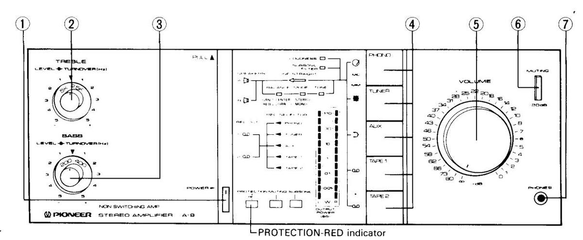
1 POWER SWITCH
Power is supplied to the stereo amplifier as soon as this switch is depressed to the ON position.
The power is turned off when the switch is released to the OFF position.
Immediately after the power switch has been set to ON, the muting circuit is actuated, the PROTECTION-RED indicator lights up red/and about 6 seconds after this when the muting circuit has been released, this indicator goes from red to green.
(2) TREBLE CONTROL
This is used to adjust the treble (high-frequency range) sound. When it is rotated clockwise from the "▼" position with the LINE STRAIGHT-OFF switch depressed (the TONE, MODE and BALANCE indicators light), the level of sound above the frequency selected by the TREBLE-TURNOVER switch is emphasized. Conversely, when the control is rotated counterclockwise from the "▼" position, the level of sound above the frequency selected by the TREBLE-TURNOVER switch is emphasized. Conversely, when the control is rotated counterclockwise from the "▼" position, the level of sound above the frequency selected by the TREBLE-TURNOVER switch is attenuated.
3 BASS CONTROL
This is used to adjust the bass (low-frequency range) sound. When it is rotated clockwise from the " ▼" position with the LINE STRAIGHT-OFF switch depressed (the TONE, MODE and BALANCE indicators light), the level of sound below the frequency selected by the BASS-TURNOVER switch is emphasized. Conversely, when the control is rotated counterclockwise from the " ▼" position, the level of sound below the frequency selected by the BASS-TURNOVER switch is attenuated.
④ FUNCTION SWITCHES
These are used to select the sound source. At the left of each switch is a function indicator (pictographic) which lights when the corresponding switch has been depressed. This indicates that the lighted function has been selected.
PHONO: Depress for playing records on a turntable connected to the PHONO jacks.
- TUNER: Depress for listening to a program on a tuner connected to the TUNER jacks.
- AUX: Depress for listening to the sound from a stereo component connected to the AUX jacks.
- TAPE 1: Depress to listen to a tape in a tape deck connected to the TAPE-1 jacks or to monitor a recording.
- TAPE 2: Depress to listen to a tape in a tape deck connected to the TAPE-2 jacks or to monitor a recording.
NOTE:
Depress only one FUNCTION switch at a time. The desired program source may not be selected if two or more switches are depressed at the same time.
(5) VOLUME CONTROL
This is used to adjust the volume of sound heard through the speakers or headphones. The scale gives the attenuation when the rated output power is 0 dB. No sound is heard when it is set to the "∞" position. To increase the volume, rotate this control slowly clockwise (Q).
6 MUTING -20 dB SWITCH
The volume is attenuated by -20 dB when this switch is depressed to the ON position (MUTING indicator lights). The switch can be used effectively when the stylus descends onto the record during record play, when the sound is to be turned down temporarily and when you want to adjust the sound precisely as you listen to a program source under low sound level conditions.
⑦ PHONES JACK
Connect the plug on your headphones to this jack when listening to a program in private.
To listen to a program through the headphones, release both the SPEAKERS A and B switches.
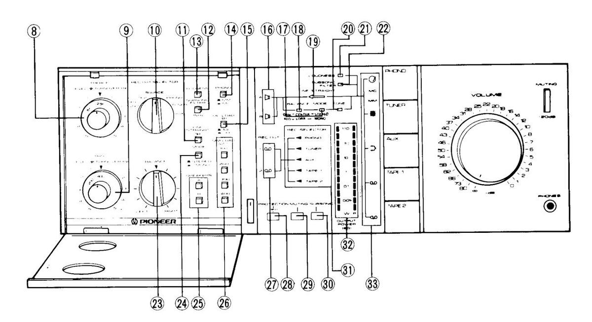
TREBLE-TURNOVER selector switch
-This is used to select the frequency at which the TREBLE
control starts to have an effect on the tone quality when it is
Allows the frequency band above 2.5 kHz to be ad-
TUNER:
The output signal from the TUNER jacks is fed out to the TAPE 1 REC and TAPE 2 REC jacks
AUX: The output signal from the AUX jacks is fed out to the TAPE 1 REC and TAPE 2 REC jacks.
(1) LINE STRAIGHT-OFF SWITCH
When this switch is released to the ON position (the LINE STRAIGHT indicator lights), the signal from the input jacks is directly sent to the power amplifier input without passing through the tone control circuit. When this switch is depressed to the OFF position, the input signal's tone quality can be adjusted with the tone controls.
12 SUBSONIC 15 Hz FILTER SWITCH
Depressing this switch to the ON position actuates the subsonic filter with the 15 Hz cutoff frequency. Once the SUB-SONIC FILTER indicator has lighted, it means that noise has been detected. Depress the SUBSONIC FILTER switch. This filter serves to attenuates frequencies lower than 15 Hz with a 12 dB/oct slope and, therefore, it can be used to suppress the ultra-low-range noise which is generated by record warp and other factors. This noise cannot actually be heard by the ear but it can cause cross modulation distortion and even speaker damage. Use this switch when required during record play.
13 LOUDNESS SWITCH
The bass and treble sound is emphasized when this switch is depressed to the ON position (LOUDNESS indicator lights) under low volume listening conditions.
When the volume of sound is low, the capability of the ear to pick up the bass and treble sound drops off, compared with high volume listening conditions. The LOUDNESS switch compensates for this characteristic of the ear. The bass and treble are emphasized when the switch is set to ON and the sound comes alive even when the volume is low.
-9
5 k: Allows the frequency band above 5 kHz to be adjusted
used for adjustment
insted
254.
9 BASS-TURNOVER SELECTOR SWITCH
This is used to select the frequency at which the BASS control starts to have an effect on the tone quality when it is used for adjustment.
- 400: Allows the frequency band below 400 Hz to be adiusted.
- 200: Allows the frequency band below 200 Hz to be adiusted.
10 REC OUT SELECTOR SWITCH
This is used to select the output signal which is fed out to the TAPE REC jacks.
- COPY 2 ► 1: The output signal is fed out from the TAPE 2 PLAY jacks to the TAPE 1 REC jacks (when dubbing a tape from TAPE 2 to TAPE 1).
- COPY 1 ► 2: The output signal is fed out from the TAPE 1 PLAY jacks to the TAPE 2 REC jacks (when dubbing a tape from TAPE 1 to TAPE 2).
- SOURCE: The output signal of the program source (PHONO, TUNER, AUX, etc.) selected by the FUNCTION switch is fed out to the TAPE 1 REC and TAPE 2 REC jacks.
- PHONO: The output signal from the PHONO jacks is fed out to the TAPE 1 REC and TAPE 2 REC jacks.
14 PHONO MM/MC SELECTOR SWITCH
This switch is set to the position that corresponds to the type of cartridge being used when listening to a record on a turntable connected to the PHONO jacks.
- MM: Set here when using an MM cartridge.
- MC: Set here when using an MC cartridge.
NOTE:
Some MC cartridges on the market have the same high output power as MM cartridges. Consult the instructions accompanying the cartridge.
(15 MC LOAD (Ω) SWITCH
This switch is set to the position that corresponds to the output impedance of the MC (moving coil) cartridge being used for record play.
16 SPEAKERS A/B INDICATORS
These light when one of the SPEAKERS switches has been depressed.
MODE INDICATOR
This lights up green (STEREO) or red (MONO) in accordance with the selected position of the MODE selector.
(18) BALANCE INDICATOR
Depending on the position of the BALANCE control, this lights up green (when the control is at the CENTER position) or red (when it is rotated LEFT or RIGHT position).
19 LINE STRAIGHT INDICATOR
This lights when the LINE STRAIGHT-OFF switch has been released to ON in place of the BALANCE, MODE and TONE indicators.
20 TONE INDICATOR
This lights when the tone control circuitry has been actuated.
(1) LOUDNESS INDICATOR
This lights when the LOUDNESS switch has been set to ON.
22 SUBSONIC FILTER INDICATOR
This lights when the SUBSONIC FILTER switch has been set to ON.
23 BALANCE CONTROL
This is used to adjust the balance of the sound from the left and right channels. When rotated clockwise from its center position, the volume of the left (L) channel is reduced; when rotated counterclockwise, the volume of the right (R) channel is reduced.
To adjust the balance, first set the BALANCE control to its center position, set the MODE selector to MONO and rotate the control so that the sound seems to be coming from the midpoint between the left and right speakers.
A MODE SELECTOR
This is used to select the mode.
- I STEREO: Set here for ordinary stereo listening.
- MONO: Set here to mix the left and right channel stereo input signals and hear them in mono through both the left and right speakers.
25 SPEAKERS SWITCHES
These are used to select the speakers through which you will listen to the sound. When one of the switches is depressed, the corresponding speaker indicator will light to indicate that the selected speakers are now working.
- A: The sound is heard from the speakers connected to the speaker A terminals.
- B: The sound is heard from the speakers connected to the speaker B terminals.
No sound will be heard when SPEAKERS A and B switches are both released. This is the position at which the sound can be heard through the headphones.
26 MM LOAD (pF) SWITCH
This switch is set to the position that corresponds to the designated load capacitance of the MM (moving magnet) cartridge being used for record play.
27) REC OUT 1, 2 INDICATORS
These indicate the tape deck which is recording in accordance with the position selected by the REC OUT SELEC-TOR switch.
28 PROTECTION-RED INDICATOR
This lights in red or green, depending on the operating mode of the power protection circuit.
29 MUTING INDICATOR
This lights in accordance with the position of the MUTING -20 dB switch.
30 SUBSONIC DETECTION INDICATOR
This lights upon detection of ultra-low-frequency noise components generated by record warp and other factors or any other noise contained in the program source. When it has lighted, depress the SUBSONIC FILTER switch to the ON position. The indicator goes off at the ON position.
31) REC SELECTOR INDICATOR
This indicates the program source (PHONO, TUNER, AUX, etc.) being recorded in accordance with the position of the REC OUT SELECTOR switch.
32 OUTPUT POWER 8 Ω METER
This indicates the output level when speakers with an 8-ohm impedance are connected to the speaker terminals. L is for the left channel and R for the right channel.
33 FUNCTION INDICATORS
The indicator corresponding to the selected FUNCTION switch lights.
3. BLOCK DIAGRAM

4. CIRCUIT DESCRIPTIONS
4.1 AMPLIFIER SECTION
Cartridge Load Selector
When the PHONO MM switch is placed to the ON position, the MM LOAD (C) switch may be positioned to provide four different levels of input capacitance (100pF, 200pF, 300pF, 400pF) in the phono input circuit. The input impedance of the equalizer amplifier is set at 50kΩ/100pF, and operating the MM LOAD (C) switch places capacitors in parallel configuration in the input circuit.
When the PHONO MC switch is placed to the ON' position, operating the MC LOAD (R) switch places input resistance into the phono input circuit to provide two different levels (33Ω, 100Ω) of cartridge loading.
MC Amplifier
To provide compatibility with low-output moving-coil cartridges, the MC amp is a flat-response voltage amplifier with a gain of 28dB. This amplifier is switched into the before stage of the equalizer amplifier by the PHONO MC switch being placed to the ON position. Circuitry is completely symmetrical, and consists of 3-stages with direct coupling. The first stage uses ultra-low noise NPN and PNP transistors, and an S/N ratio of 74dB (100µV input, IHF-A) is attained.
Equalizer Amplifier
The first stage is a cascade connected differential amp using an ultra-low noise twin FET and NPN twin transistor. The second stage differential amp, in combination with the modified current mirror of the third stage serves to cancel even-harmonic distortion components, and the output stage is a class A configuration symmetrical complementary SEPP.
A DC servocontrol circuit is also built into the equalizer amplifier. This circuit serves to hold DC area gain of the equalizer amplifier to less than 1, so that even when an extremely low frequency is input into the amp, it is practically eliminated from the output. This circuit also functions to minimize DC drift at the output mid-point. Output is returned to the input stage through the integrating amp (consisting of operational amplifier IC µPC741C), holding circuit gain in the DC area to less than 1.
Using FETs in the first stage, combined with the DC servocontrol function eliminates the need for coupling capacitors between inputs and outputs, and there is no sound degradation due to capacitors.
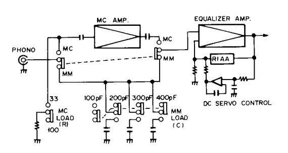
Fig. 4-1 Cartridge load selector circuit
Tone Control
Tone control is by a BAX type tone control circuit with a turnover frequency selector. To improve S/N ratio, a line amp has been added to the before stage. Both line amp and tone amp use operational amplifiers (IC µPC4558DX).
An attenuator is used in the output circuit to equalize the level with the line straight circuit. This brings the total gain of the tone control section to 0dB.
Line Straight Circuit
When the LINE STRAIGHT OFF switch is in the LINE STRAIGHT position, the tone control circuit (including line amp), MODE (STEREO/ MONO) switch, and BALANCE control are bypassed, and the signal circuit is directly coupled from the VOLUME control to the power amp for pure DC amplification.
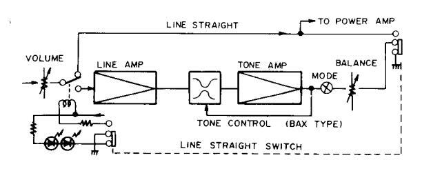
Fig. 4-2 Line straight circuit
Power Amplifier
The first stage is a cascade connected differential amplifier using a low noise twin FET and an NPN twin transistor, and the load circuit is the current mirror type. The power stage is a 3-stage Darlington arrangement, with the final stage a parallel SEPP
Bias voltage is supplied to the power stages through the high speed bias servocontrol circuit. The B class push-pull power stage alternately drives the N and P channels during each helf-cycle, and the high speed bias servocontrol circuit controls the bias voltage so that the idle channel of the power stage is maintained in the active region. (Refer to the section on the High Speed Bias Servocontrol Circuit for operational details.)
The power amplifier has a built in DC servocontrol circuit functioning to reduce gain in the DC area to less than 1, so that even if a DC input were present, it would, for all practical purposes, not appear at the output. This circuit also functions to hold center-point DC drift to a minimum. The signal is returned from the output stage to the input stage via the integrating amp (constructed of an operational amplifier), and circuit gain in the DC area is held to less than 1.
The use of FETs in the first stage, combined with the DC servocontrol circuit eliminate the need for coupling capacitors between inputs and outputs, thereby preserving tonal quality.
High Speed Bias Servocontrol Circuit
By operating the power stage only within the active region (no possible cut-off) and with minimum idle current, the high speed bias servocontrol circuit prevents the generation of switching distortion and reduces heat loss.
This circuit is outlined in Fig. 4-4. When there is no signal applied to the circuit, Q1 and Q2 are almost cut off, while Q3 and Q4 will be on. The voltage across the collector and base of both of these transistors (Q3 and Q4) at this time may be disregarded. Consequently, with the power stage bias circuit consisting of 4 PN junctions formed by Q3 D3 and Q4, and VR1.
With R1 and D1 ensuring a constant flow of current, the base of Q1 and point X may be brought to the same level on an AC basis (level fluctuations due to the signal) by a simple shift in DC level. Furthermore, Q1 may be considered emitter-follower with R3 as the emitter resistance.
When the voltage across points Y and X is increased by the positive portion of the signal applied to this circuit. it becomes the input signal of this emitter-follower (Q1). Since the emitter-follower voltage gain is practically 1 a voltage more or less equal to that of the input signal (that is the voltage increase across points Y and X) is produced at R3. And the R3 voltage is the voltage applied across the base and collector of Q3 which forms part of the power stage bias circuit. So the bias voltage applied to Q3 will be in excess by the same amount the voltage across points Y and X is increased (by positive portion of the signal) above the voltage level when no signal is being applied. Consequently, the increase in voltage across points Y and X cancels the decrease in voltage across points X and Z, thereby maintaining the idle current without cutting the PNP power stage off (noting that there actually is a slight decrease in current). For the negative portions of the signal Q2 and Q4 are operated in the same manner. thereby preventing the NPN power stage form being cut off.

Fig. 4-3 Power amplifier circuit
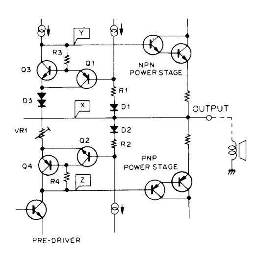
Fig. 4-4 Basic circuitry of High speed bias servocontrol circuit
4.2 POWER INDICATOR CIRCUIT
The A-9 indicates power output from 0.01 watt to 110 watts peak power using a 12 point LED display without range switching. The power amplifier output signal is passed through a low-pass filter, then input to IC (TA7318P-A). This IC consists of a detector circuit, compressor (40dB), and peak-hold circuit for each channel. The signal, after being processed by this IC, is input to the LED power meter module containing the voltage comparators and LED drivers. Here, the LEDs are driven (illuminated) in accordance with the input level.
4.3 PROTECTION CIRCUIT
The purpose of this circuit is to protect both the speakers and the power amplifiers. The relay in the output circuit is automatically opened in any of the following cases:
- 1. During the "transient operations" when the power supply is turned on and off.
- Upon detection of a DC voltage in the output circuit, caused by component failure or accident.
- Upon detection of an overload, caused by a short circuit in the load.
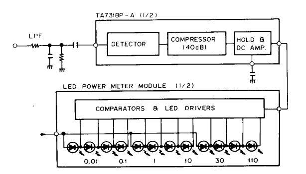
Fig. 4-5 Power indicator circuit
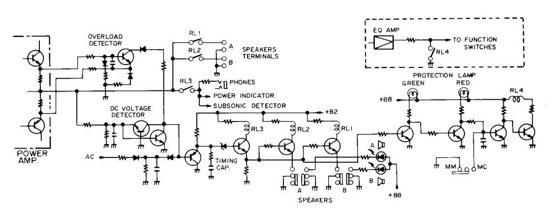
Fig. 4-6 Protection circuit
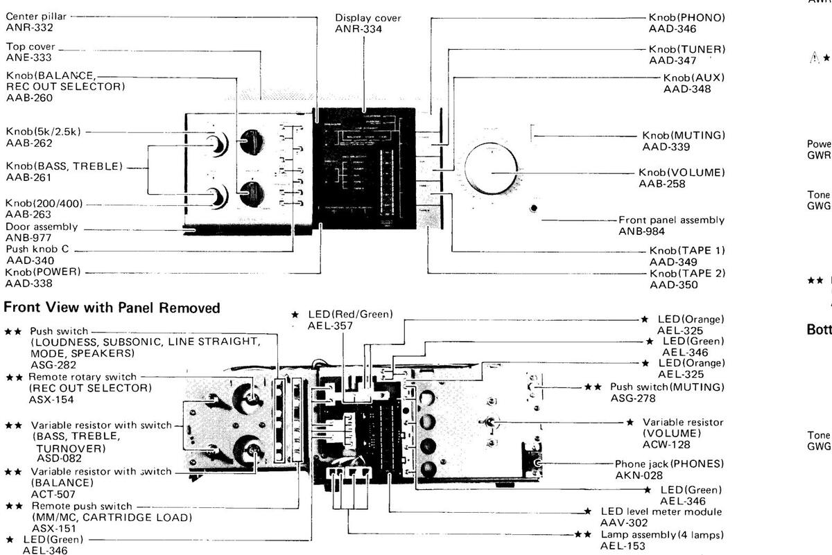
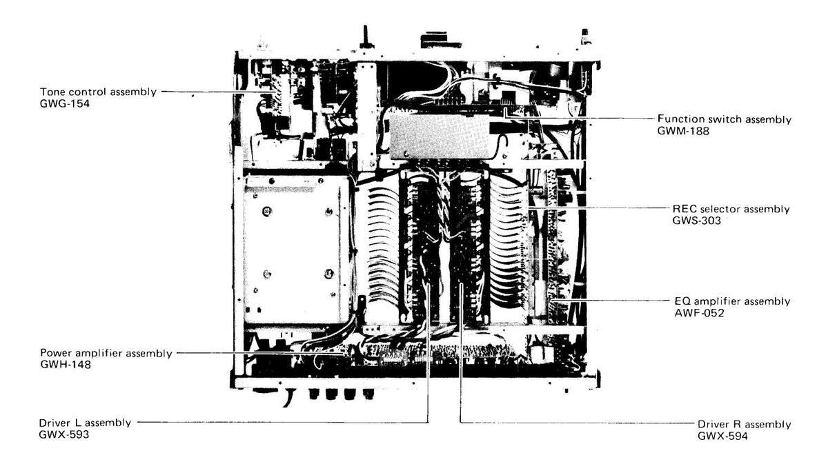
5. PARTS LOCATION
• The A mark found on some component parts indicates the importance of the The mark journa on some component parts matures the importance of the safety factor of the part Therefore when replacing he sure to use parts of identical designation
-
For your Parts Stock Control the fast moving items are indicated with the marks ★★ and ★
- ★★ GENERALLY MOVES FASTER THAN ★
This classification shall be adjusted by each distributor because it depends on model number, temperature, humidity, etc.
Front Panol View
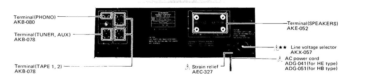
Rear Panel View
Ton
Power Power
Ponula AMD
Power GWR-
GWG
** F
Rotte
Tone
GWH-
Driver GWX-{
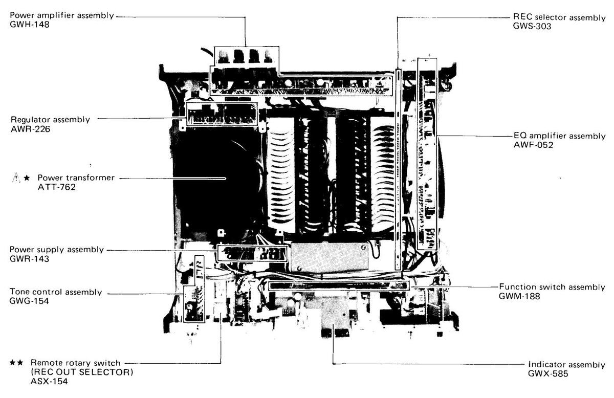
Top View
Bottom View
6. PACKING

| lark | No. | Part No. | Description |
|---|---|---|---|
| 1. | ARB-399 |
Operating instructions
(English) |
|
| ARD-156 |
Operating instructions
(German/French/Italian, HE type only) |
||
| 2. | AHA-279 | Side pad L | |
| 3. | AHA-280 | Side pad R | |
| 4. | AHD-874 | Packing case | |
| 5. | AHC-063 | Inside packing |
| here |
|---|
| ? are |
| The |
| h of |
| iv be |
| stage |
| ed by |
| jeu - s |
| ow of |
| av be |
| (level |
| o shift |
| idered |
| tonce |
| v is in- |
| A 15 m |
| gnar ap |
| ignar of |
| itter-ior |
| ige more |
| (that is |
| nd A) |
| le voltag |
| 23 which |
| it. So u |
| ess by ti |
| [ and X |
| nal) abo |
| ng appli |
| ross por |
| tage acr |
| he idle ( |
| r stage |
| decreas |
| f the sig |
| me mar |
| C |

Δ

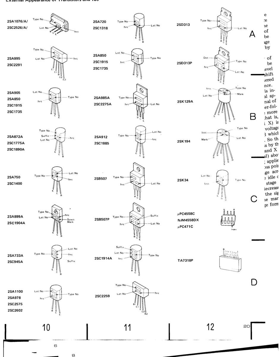
External Appearance of Transistors and ICs
10
A-9
12
8. EXPLODED VIEW
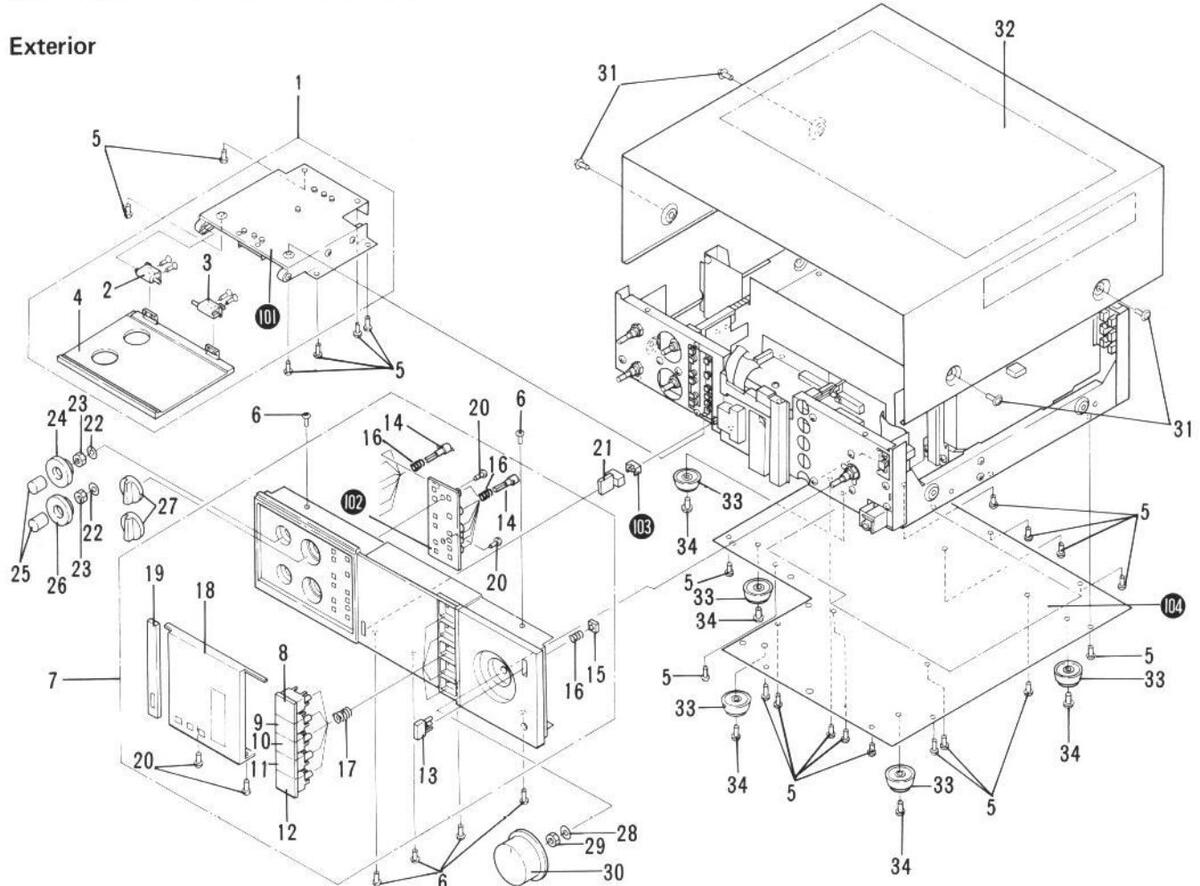
Exterior Components
| Mark | No. | Part No. | Description | Mark | No. | Part No. | Description |
|---|---|---|---|---|---|---|---|
| 1. | AXC-003 | Door mechanism assembly | 21. | AAD-338 | Knob(POWER) | ||
| 2. | ANR-340 | Hinge L | 22. | WAX1F160U050 | Washer 11¢ | ||
| 3. | ANR-341 | Hinge R | 23. | NKX1FUC | Nut M11 | ||
| 4. | ANB-977 | Door assembly | 24. | AAB-262 | Knob(5k/2.5k) | ||
| 5. | VBZ30P060FMC | Screw 3x6 | 25. | AAB-261 | Knob(BASS, TREBLE) | ||
| 6. | VBZ30P080FMC | Screw 3x8 | 26. | AAB-263 | Knob(200/400) | ||
| 7. | ANB-984 | Front panel assembly | 27. | AAB-260 | Knob(BALANCE, REC OUT | ||
| 8. | AAD-346 | Knob(PHONO) | SELECTOR) | ||||
| 9. | AAD-347 | Knob(TUNER) | 28. | WA92F140U100 | Washer 9.2¢ | ||
| 10. | AAD-348 | Knob(AUX) | 29. | NK90FUC | Nut M9 | ||
| 30. | AAB-258 | Knob(VOLUME) | |||||
| 11. | AAD-349 | Knob(TAPE 1) | |||||
| 12. | AAD-350 | Knob(TAPE 2) | 31. | ABA-193 | Screw | ||
| 13. | AAD-339 | Knob(MUTING) | 32. | ANE-333 | Top cover | ||
| 14. | AAD-340 | Push knob C | 33. | AEC-083 | Cabinet bumper | ||
| 15. | AEC-564 | Knob holder | 34. | VTZ40P120FMC | Screw 4x12 | ||
| 16. | ABH-045 | Coiled spring | 101. | Door holder | |||
| 17. | ABH-069 | Coiled spring | 102. | Knob spacer | |||
| 18. | ANR-334 | Display cover | 103. | Flexible ring | |||
| 19. | ANR-332 | Center pillar | 104. | Bottom plate | |||
| 20. | VBZ30P080FZK | Screw 3x8 |
NOTES:
- Parts without part number cannot be supplied.
- The A mark found on some component parts indicates the importance of the safety factor of the part. Therefore, when replacing, be sure to use parts of identical designation.
-
For your Parts Stock Control, the fast moving items are indicated with the marks ★★ and ★.
- ★★ GENERALLY MOVES FASTER THAN ★.
This classification shall be adjusted by each distributor because it depends on model number, temperature, humidity, etc.
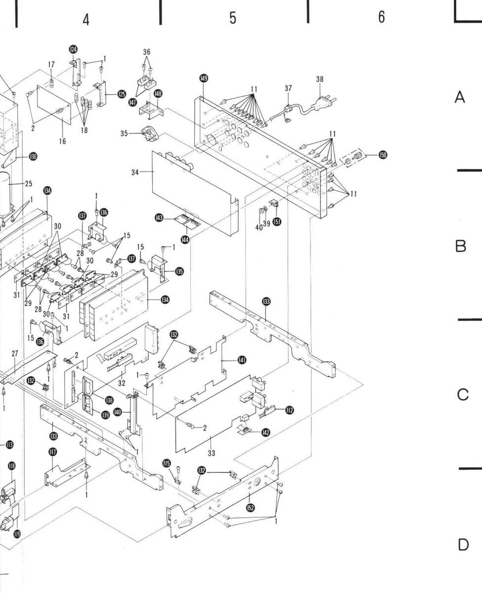
Interior Components
| Mark | No. | Part No. | Description | Mark No | э. | Part No. | Description |
|---|---|---|---|---|---|---|---|
| 1. | VBZ30P060FMC | Screw 3×6 | 10 | 01. | Side frame L | ||
| 2. | AEC-352 | Nylon rivet | 10 | 02. | Connector assembly | ||
| 3. | GWG-154 | Tone control assembly | 10 | 03. | Connector assembly | ||
| 4. | ABN-048 | Washerfaced nut | 10 | 04. | Holder | ||
| ** | 5. | ASX-154 | Remote rotary switch | 10 | 05. | Remote belt | |
| 6. | ABN-066 | Union nut | 1( | 06. | Balance control assembly | ||
| 7. | GWM-188 | Function switch assembly | 10 | 07. | Connector E assembly | ||
| 8 | ABA-261 | Screw | 10 | 08. | Switch assembly | ||
| 9 | ABN-046 | Union nut | 10 | 09. | Load selector assembly | ||
| ∧ ★★ | 10. | ASG-535 | Push switch (POWER) | 1 | 10. | Holder | |
| 11. | BBT30P080FZK | Screw 3×8 | 1. | 11. | Connector D assembly | ||
| 12. | ABA-214 | Screw | 11 | 12. | Remote belt | ||
| ** | 13 | AEL-153 | Lamp assembly (4 lamps) | 11 | 13. | Volume control assembly | |
| 14 | GWX-585 | Indicator assembly | 11 | 14. | Connector C assembly | ||
| 15. | VBZ30P080FMC | Screw 3x8 | 1 | 15. | Ground terminal 2-P | ||
| 16. | AWR-226 | Regulator assembly | 1 | 16. | Slide plate | ||
| A ++ | 17. | AEK-015 | Fuse(T5A250V) | 11 | 17. | Sub-frame | |
| A ++ | 18 | AEK-402 | Fuse(T1A250V) | 1 | 18. | AF muting assembly | |
| ш | 19. | VTZ40P080FMC | Screw 4x8 | 1 | 19. | Headphones jack assembly | |
| ≜ ★ | 20. | ATT-762 | Power transformer | 1: | 20. | Switch holder | |
| 21. | GWR-143 | Power supply assembly | 1: | 21. | Panel stay | ||
| A ** | 22. | AEK-405 | Fuse(T1.6A250V) | 1: | 22. | Lamp holder A | |
| 23. | WS50FMC | Spring washer 50 | 1: | 23. | Lamp holder B | ||
| 24. | ABA-100 | Screw 5x12 | 1: | 24. | P.C.B. holder B | ||
| 25. | AWX-205 | Capacitors assembly | 1: | 25. | P.C.B. holder C | ||
| 26. | GWX-593 | Driver Lassembly | 1: | 26. | P.C.B. holder D | ||
| 27. | GWX-594 | Driver R assembly | 1: | 27. | P.C.B. holder E | ||
| 28. | ABA-258 | Screw | 1: | 28. | Transformer frame | ||
| A ** | 29. | 2SA1076/A/-B* | 1: | 29. | Shield cover A | ||
| (2SA1076/A/-G*) | *hfe should have the same | 1: | 30. | Capacitors holder | |||
| A ** | 30. | 2SC2526/A/-B* | value. | ||||
| (2SC2526/A/-G*) | 1: | 31. | Shield cover B | ||||
| 1: | 32. | Wire saddle | |||||
| 31. | AEC-488 | Insulator wafer | 1: | 33. | Center frame | ||
| 32. | GWS-303 | REC selector assembly | 1: | 34. | Heat sink | ||
| 33. | AWF-052 | EQ amplifier assembly | 1: | 35. | Holder A | ||
| 34. | GWH-148 | Power amplifier assembly | |||||
| A ** | 35. | AKX-057 | Line voltage selector | 1; | 36. | Holder B | |
| 0.04.0 | 1: | 37. | Clamp plate | ||||
| 36. | VBZ30P120FMC | Screw 3x12 | 1: | 38. | Connector A assembly | ||
| A | 37. | AEC-327 | Strain relief | 1: | 39. | Connector B assembly | |
| A | 38. | ADG-041 | AC power cord (for HE type) | 14 | 40. | P.C.B. holder A | |
| A | ADG-051 | AC power cord(for HB type) | |||||
| Accessed in the second | 39. | WG70FMC | Locking washer | 14 | 41. | Shield plate | |
| 40 | R71-010 | Nut M7 | 1, | 42 | Connector assembly |

| Mark | No. | Part No. | Description | Mark | No. | Part No. | Description |
|---|---|---|---|---|---|---|---|
| 143. | Connector assembly | 148. | Shelf | ||||
| 144. | Connector assembly | 149. | Rear panel | ||||
| 145. | Lever assembly | 150. | Terminal (GND) | ||||
| 146. | Plate | 151. | Grounding plate | ||||
| 147. | Terminal strip 2-P | 152. | Side frame R | ||||
| 23 | 1 | 2 | - I | 3 |
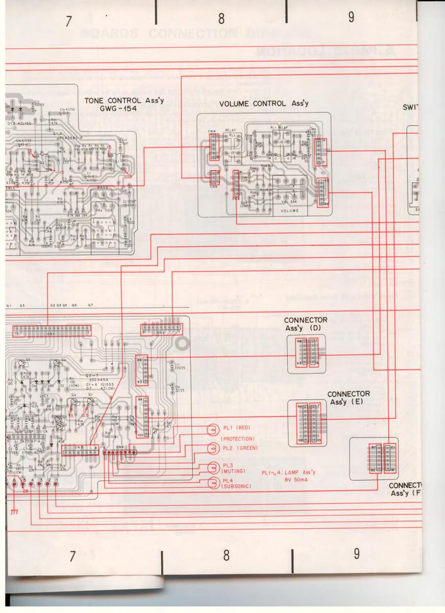
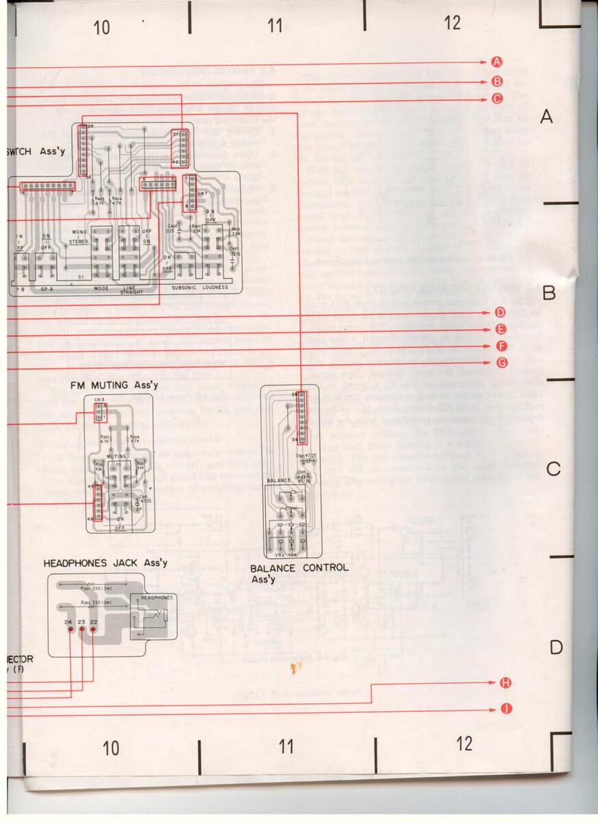
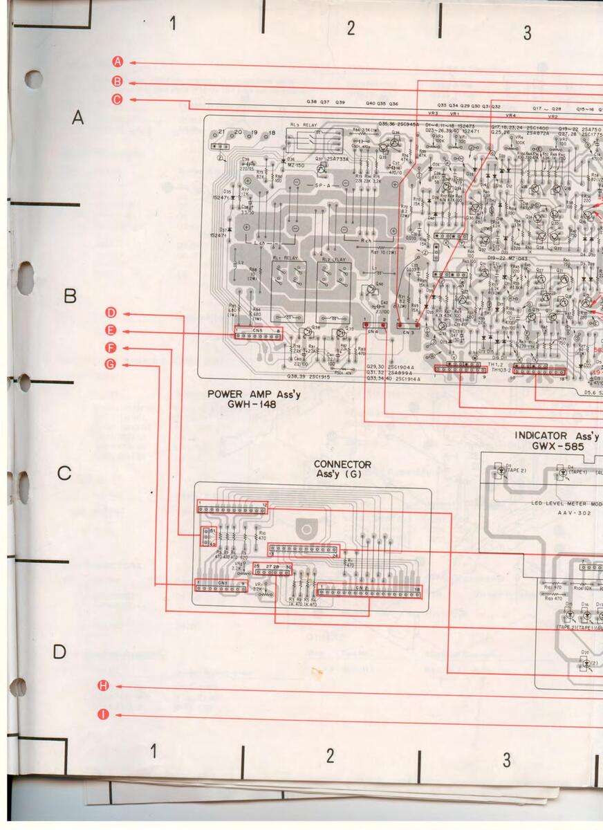
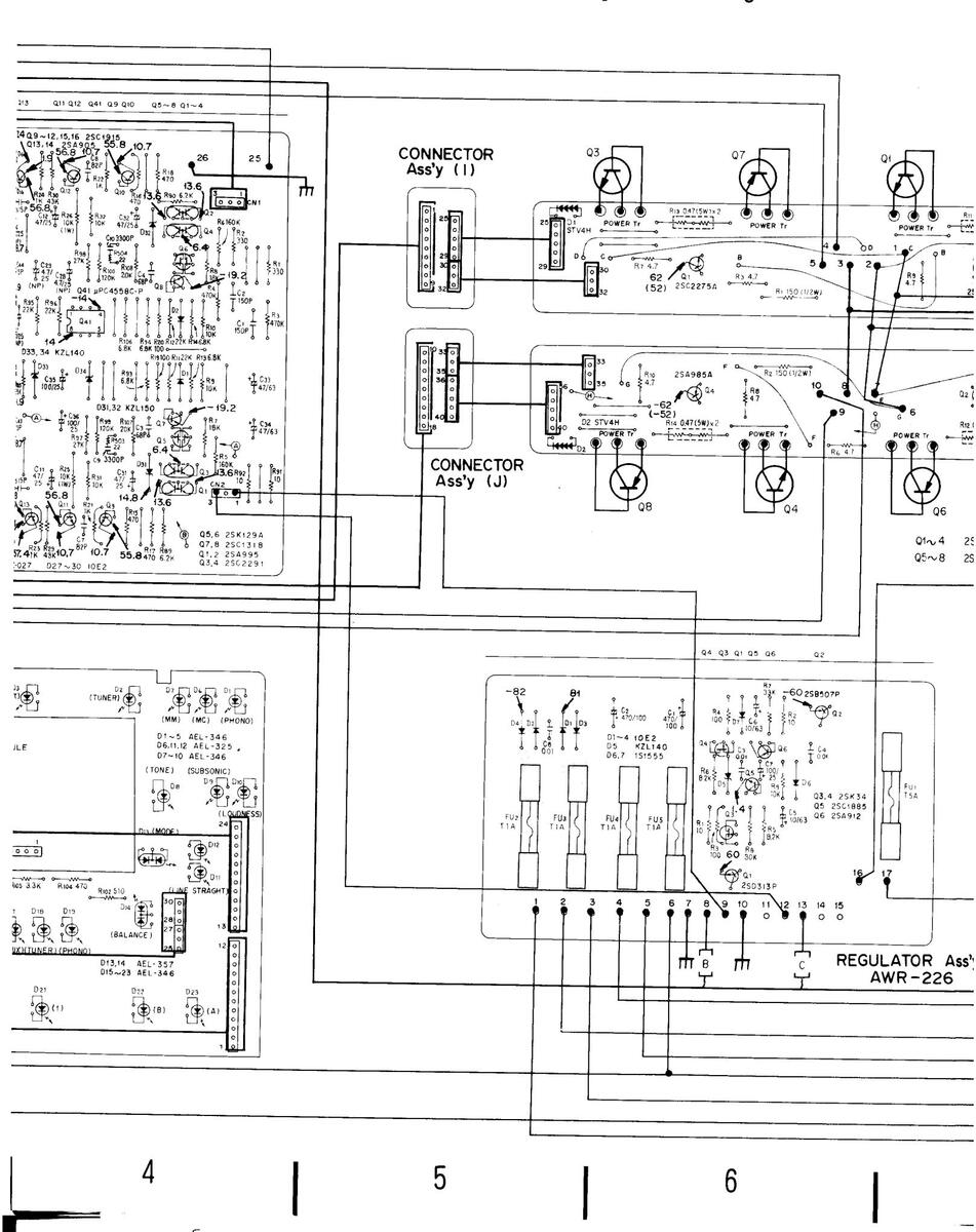
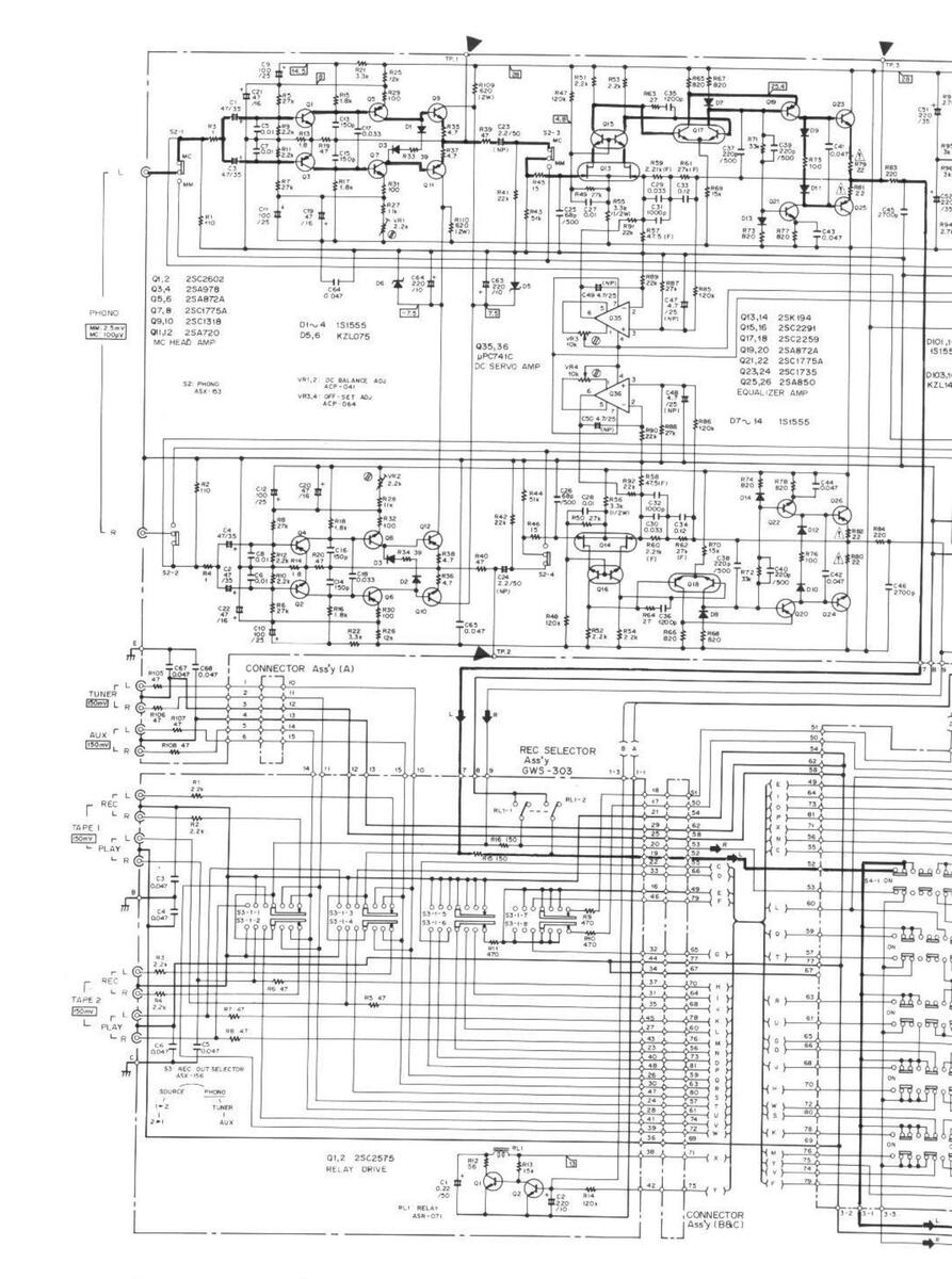
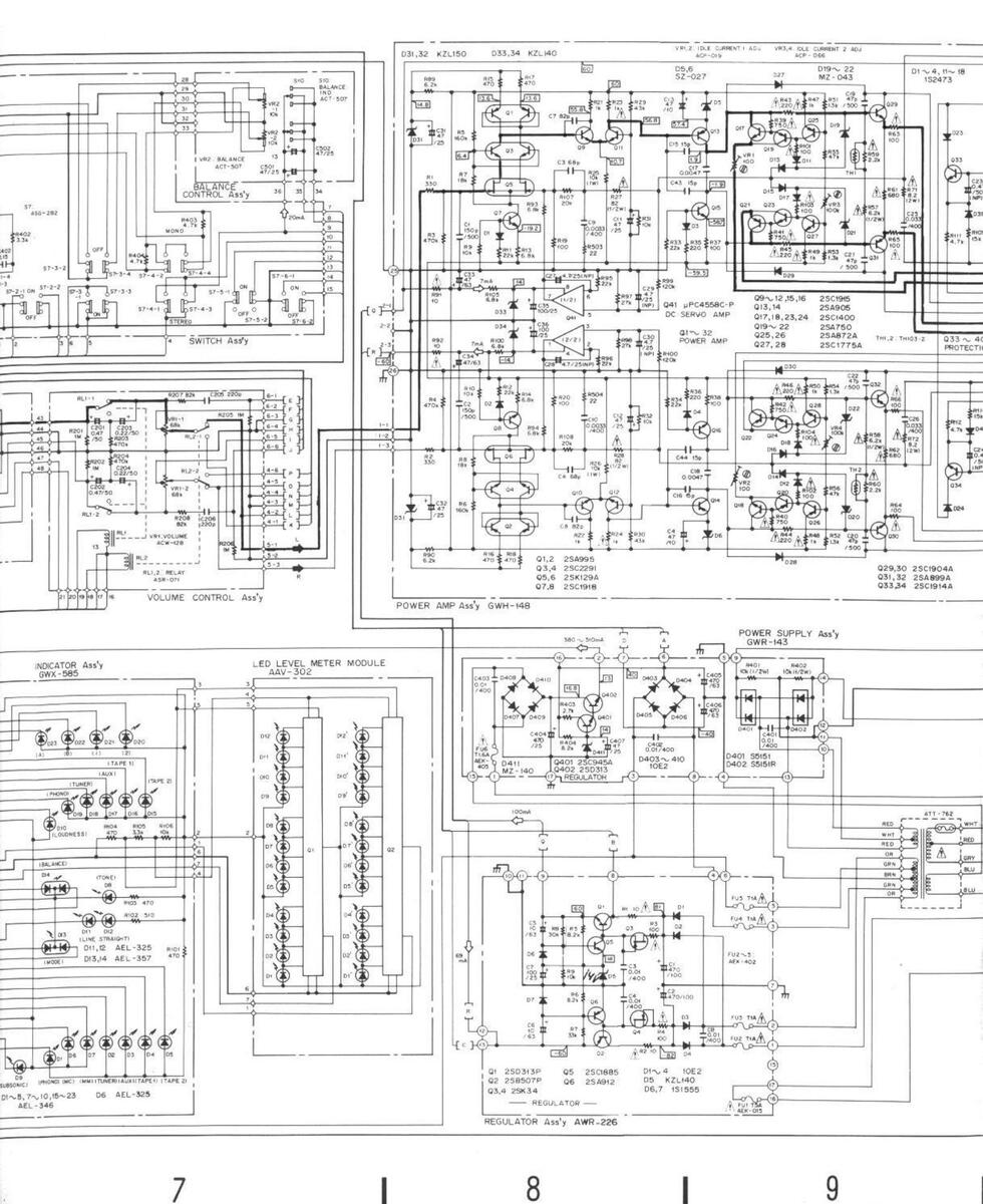
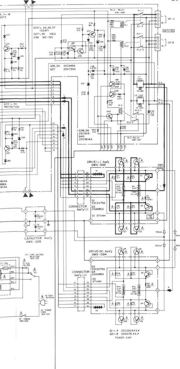
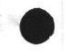
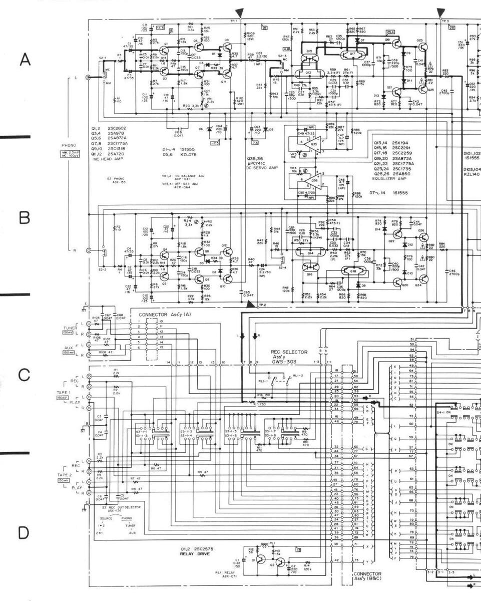
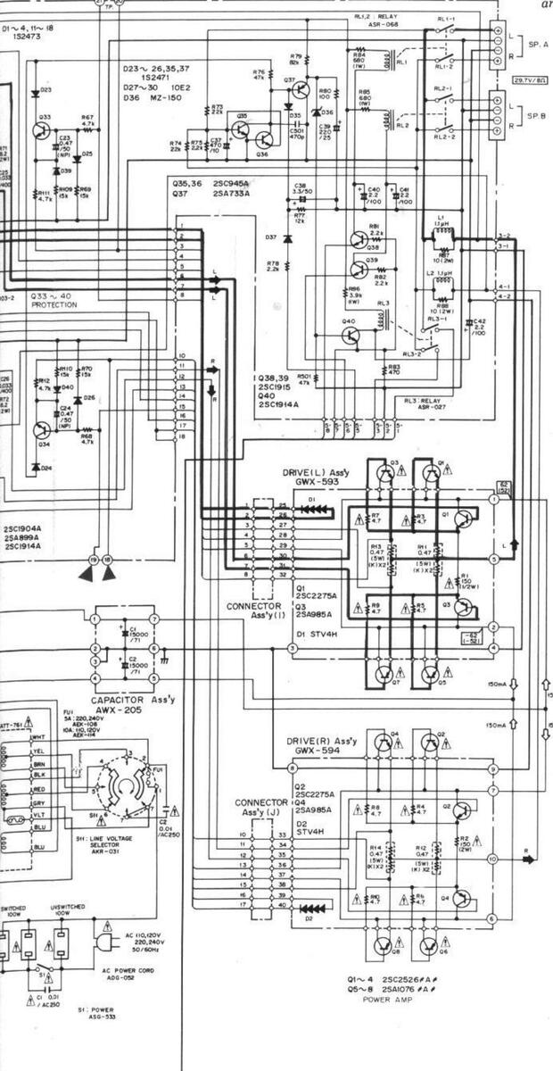
9. SCHEMATIC DIAGRAM
А
В
С
D
2
2
3


Α
В
С
D
28
NOTE:
The indicated semiconductors are representative ones only. Other alternative semiconductors may be used and are listed in the parts list.

3 VOLTAGE, CURRENT Signar voltage at 110 W + 110 W 821 output 11k+4 D voltage (V) at no input signar Value in { I a DC voltage at rated power
Value in { | is DC voltage at rated power
The M mark found on some component parts indicates the importance of the safety factor of the part. Therefore, when replacing be sure to use parts of identical designation.
| S1 POWER | ON - OFF |
|---|---|
| S2: PHONO (SIGNAL) | MC - MM |
| S3 REC OUT SELECTOR | |
| 2+1-1+2-SOURCE - | PHONO - TUNER - AUX |
| S4-I: FUNCTION (PHONO) | ON-OFF |
| S4-2 FUNCTION (TUNER) | ON - OFF |
| S4-3 FUNCTION (AUX) | ON - OFF |
| S4-4 FUNCTION (TAPE () | ON - OFF |
| 54-5: FUNCTION (TAPE 2) | ON - OFF |
| 55 : MUTING (-20dB) | ON - OFF |
| 56-1 MM LOAD (400p) | ON - OFF |
| 56-2: MM LOAD (300p) | ON - OFF |
| 56-3 MM LOAD (200p) | ON -OFF |
| S6-4. MM LOAD (100p) | ON - OFF |
| S6-5 MC LOAD 1 | 00n - 33n |
| S6-6. PHONO (IND) | MC - MM |
| S7-1: LOUDNESS | ON - OFF |
| S7-2 SUBSONIC FILTER (15 | Hz) ON - OFF |
| 57-3 LINE STRAIGHT | ON - OFF |
| S7-4 MODE | STEREO - MONO |
| S7-5 SPEAKERS (A) | ON - OFF |
| 57-6: SPEAKERS (8) | ON - OFF |
| S8 TURNOVER (TREBLE | ) 2.5kHz - 5kHz |
| 59 TURNOVER (BASS) | 400Hz - 200Hz |
| STO BALANCE (IND) | ON - OFF |
| SHI : LINE VOLTAGE SELE | CTOR - 240V |
|
ۇ.
And sectors in a local sector in a |
awitch motifion |
This is the basic schematic diagram, but the actual circuit may van due to improvements in design.
11
SISTORS: dicated in (1, 50%, 45% tolerance unless otherwise noted k, k, MU, (F) : 1%, (G) : 2%, (K) = 10%, (M) : ± 20% tolerance PACITORS: Deated in capacity (LF)/voltage (V) unless otherwise noted p : i fication without voltage is 50V excent electrolytic capacit
10. ELECTRICAL PARTS LIST
A-9
-
When ordering resistors first convert resistance values into code form as shown in the following resistors,
-
Ex. 1 When there are 2 effective digits (any digit apart from 0), such as 560 ohm and 47k ohm (tolerance is shown by J = 5%, and K = 10%). 5600
- k ohm (tolerance is snown by J = 5%, and K = 10%). 56 × 101 561 .... RD4PS [56] [] J 47 × 103 473 .... RD4PS [4] [] [] J 20012 1760 0.5Ω 0R5 ..... RN2H Q R 5 K 010 ..... RS1P Q 1 Q K
-
Ex. 2 When there are 3 effective digits (such as in high precision metal film resistore 5.62kΩ 562 × 100 5621..... RN4SR 5621 F
-
Ex. 1 When there are 2 effective digits (any digit apart from 0), such as 560 ohm and 47k ohm (tolerance is shown by J = 5%, and K = 10%). 5600
- The i. mark found on some component parts indicates the importance of the safety factor of the part. Therefore, when replacing, be sure to use parts of identical designation.
-
For your Parts Stock Control, the fast moving items are indicated with the marks ** and * ★★ ana ★. ★★ GENERALLY MOVES FASTER THAN ★
- This classification shall be adjusted by each distributor because it depends on model number, temperature humidity etc
Miscellaneous Parts
SEMICONDUCTORS
OTHERS
| Mark | Part No. | Symbol & Description | Mark | Part No. | Symbol | & Description |
|---|---|---|---|---|---|---|
| ∧ ★★ |
2SC2526/A/-B*
(2SC2526/A/-G*) |
Q1, Q3, Q5, Q7 | A * | ATT-762 | Power transformer | |
| ★★ |
2SA1076/A/-B*
(2SA1076/A/-G*) *hfe of Q1-Q8 should i |
Q2, Q4, Q6, Q8
have the same value. |
A_ | ACG-001 | C1 |
(220V/240V)
Ceramic capacitor (0.01/AC250V) |
| FUSES |
**
^ |
AEL-153
ASG-535 |
PL1
S1 |
Lamp assembly
Push switch (POWER) |
||
|
Mark
★★ |
Part No. | Symbol & Description | A ★★ |
AKX-057
ADG-041 ADG-051 |
S10
AC powe AC powe |
Line voltage selector
r cord (for HE type) r cord (for HB type) |
| 101 | (ISA250V) | ||
|---|---|---|---|
| _∄_★★ | AEK-402 | FU2-FU5 | (T1A250V) |
| ≜ ★★ | AEK-405 | FU6 | (T1.6A250V) |
Power Amplifier Assembly (GWH-148)
P.C. BOARD ASSEMBLIES
CAPACITORS
| Mark | Part No. | Symbol & Description | Mark | Part No. | Symbol & Description |
|---|---|---|---|---|---|
|
GWH-148
GWR-143 GWG-154 AWF-052 GWS-303 |
Power amplifier assembly
Power supply assembly Tone control assembly EQ amplifier assembly REC selector assembly |
ACF-015
ACF-017 CCDSL 680J 50 CCDSL 820J 50 CCDSL 150J 50 |
C1, C2 Mica (150p/500V)
C19-C22 Mica (47p/500V) C3, C4 C7, C8 C15, C16, C43, C44 |
||
|
GWM-188
GWX-585 AWX-205 GWX-593 GWX-594 |
Function switch assembly
Indicator assembly Capacitors assembly Driver L assembly Driver R assembly |
CQMA 472J 50
CQMA 332K 400 CQMA 333K 400 ACH-318 CEA 470M 25L |
C17, C18
C9, C10 C25, C26 C27-C30 Electrolytic (4.7/25V, NP) C11, C12, C31, C32 |
||
| AWR-226 | Regulator assembly |
CEA 470M 63L
CEA 101M 25L CEA 470M 10L CEA 471M 10L CEA 221M 25L |
C33, C34
C35, C36 C13, C14 C37 C39 |
||
|
CEA 2R2M 100L
CEA 3R3M 50L ACH-356 CKDYB 471K 50 |
C40-C42
C38 C23, C24 Electrolytic (0.47/50, NP) C501 |
RESISTORS
★ ACP.019
★ ACP-066
BD%PSE DETEL
OTHERS
Part No
| Note: | When ordering resistors, convert the resistance value | |
|---|---|---|
| into code form, and then rewrite the part no. as before. | - |
Mark Mark Part No. Symbol & Description
B101-B104
R27, R28, R57, R58
VB1 VB2 Semifixed (100-B)
VR1, VR2 Semifixed (100-B)
** ASR-000 B13 ASR-027 Torminal PMZ30P060EMC Screw 3x6 VBZ30P060FMC Screw 3x6
BL1 BL2 Belay Bolov
Symbol & Description
Symbol & Description
R101-R104 R23, R24, R39-R50, R59-R66, R91, Power Supply Assembly (GWR-143)
CAPACITORS
|
R27, R28, R57, R58
R25, R26, R84-R86 |
CAPACITORS | ||||
|---|---|---|---|---|---|
| , | Mark | Part No. | Symbol & Descripti | ||
|
RS2P 100J
RN2P 8R2K RD%PM □□□ J |
R87, R88
R71, R72 R1, R2, R5-R22, R29-R38, R51-R56, R67-R70, R73-R83, R89, R90, R93-R100, R105-R112, R501, R503, R504 |
CEA 471M 63L
CEA 471M 25L CEA 470M 25L CQMA 103K 400 |
C405, C406
C404 C407 C401-C403 |
||
| P3 P4 | RESIS | TORS | |||
B3. B4
D1-D4, D11-D18
D5 D6
D19-D22
_ .0 022 D31, D32
D33, D34
TH1 TH2
D36 D27-D30
D23-D26, D35, D37, D39, D40
Mark Part No
| SEIMICO | UNDUCTORS | RD%PM272J | R403 | ||
|---|---|---|---|---|---|
| Mark | Part No. | Symbol & Description | RD¼PM822J | R404 | |
| RD½PS103J | R401, R402 | ||||
| ** | 25A995 | 01, 02 | |||
| ** | 2SC2291 | Q3, Q4 | SEMIC | ||
| ** | 2SC1318 | Q7, Q8 | SEIVILU | ONDOCIONS | |
| ** | 2SC1915 | Q9-Q12, Q15, Q16, Q38, Q39 | Mark | Part No. | Symbol & Description |
| ** | 2SA905 | Q13, Q14 | |||
| ** | 2SC945A | Q401 | |||
| ** | 2SC1775A-E | Q27, Q28 | (2SC2575) | ||
| ** | 2SA872A-E | Q25, Q26 | ** | 2SD313 | Q402 |
| ** | 2SC1400-E* | Q17, Q18, Q23, Q24 | |||
| (2SC1400-U*) | * | S5151 | D401 | ||
| ** | 2SA750-E* | Q19-Q22 | * | MZ-140 | D411 |
| (2SA750-U*) | * | 10E2 | D403-D410 | ||
| *hfe of Q17-Q24 sho | ould have the same value. | * | S5151R | D402 | |
| ** | 2SK129A | Q5, Q6 | OTHER | 1 | |
| ** | 2SC1885 | Q29, Q30 | OTTEN | ||
| ** | 2SA912 | Q31, Q32 | Mark | Part No. | Symbol & Description |
| ** | 2SC1914A | Q33, Q34, Q40 | |||
| ** | 2SC945A | Q35, Q36 | PMZ30P060FMC | Screw 3×6 | |
| (2SC2575) | |||||
| ** | 2547334 | 037 | Headpl | hone Jack Assem | bly |
| (2SA1100) | Mark | Part No | Sumbal 9 Data 1 1 | ||
| ** | µPC4558C-P | 041 | Symbol & Description | ||
| B$2P 221 | | P201 P202 |
AKN-028 Phone jack (PHONES)
Regulator Assembly (AWR-226)
CAPACITORS
Part No. Mark Symbol & Description ACH-343 C1. C2 Electrolytic (470/100V) CEA 100M 631 C5, C6 CEA 101M 25L C7 CQMA 103K 400 C3, C4, C8
30
•
152473
★ 1$2471
★ MZ-043
★ KZL150
★ K71140
★ MZ-150
★ TH103-2
★ 10E2
SZ-027
(1$1555)
| RESIS | TORS | Mark | Part No. | Sym | bol & D | escription | |
|---|---|---|---|---|---|---|---|
| Note: |
When ordering resist
into code form, and |
tors, convert the resistance value
then rewrite the part no. as before. |
RD¼PM 105J
RD¼PM 470J |
R10
R10 |
)1-R106
)7, R108 |
||
| Mark | Part No. | Symbol & Description | |||||
| ð. |
RD%PMFL DDD J
RD%PM === J |
R1-R4
R5-R9 |
* ** | ASX-151 | 56 |
Remote
(MM/N |
e push switch
IC, CARTRIDGE LOAD) |
| SEMIC | ONDUCTORS | Switch | Assembly | ||||
| Mark | Part No. | Symbol & Description | Mark | Part No. | Sym | ıbol & D | escription |
| · | CQMA 154J 50 | C40 | 1, C402 | ||||
| ** | 2SD313P | Q1 | |||||
| ** | 2SB507P | Q2 | RD%PM 472J | R40 | )3. R404 | ||
| ** | 2SC1885-R | Q5 | -, | ||||
| ** | 2SA912-R | Q6 | ** | ASG-282 | S 7 | Push sv | |
| ** | 2SK34-D | Q3, Q4 | 100 202 | 0, | SUBSC | NIC, LINE STRAIGHT, | |
| * | 10E2 | D1-D4 | MODE | , SPEAKERS) | |||
| * | ▲ 1S1555 | D6, D7 | |||||
| (1S2473) | Delene | Control Accor | اما م | ||||
| * | KZL140 | D5 | Daland | e Control Assen | libiy | ||
| Mark | Part No. | Syn | nbol & C | Description | |||
| ΟΤΗΕ | R | CEA 470M 25L | C50 | )1, C502 | |||
| Mark | Part No. | Symbol & Description | . * * | ACT-507 | VR | 2 (S10) | Variable resistor with |
| BB 730 DOCO EMO | S | switch (BALANCE) |
PBZ30P060EMC Screw 3x6
Tone Control Assembly (GWG-154)
AF Muting Assembly
| CAPACITORS | Mark | Part No. | Symbo | ol & Description | ||
|---|---|---|---|---|---|---|
| Mark | Part No. | Symbol & Description | CEA 470M 25L | C301 | ||
|
CEANL 4R7M 50
CEA 101M 25L |
C1-C4, C15, C16
C17, C18 |
RD¼PM 433J
RD¼PM 472J |
R301-
R303, |
R302
R304 |
||
|
CQMA 122J 50
CQMA 272J 50 CQMA 223J 50 |
C13, C14
C5-C8 C19, C20 C9-C12 |
** | ASG-278 | S5 | Push switch (MUTING) | |
RESISTORS
Volume Control Assembly CARACITORS
| CALACITORS | ||||||
|---|---|---|---|---|---|---|
| Mark | Part No. | Symbol & Description | — Mark | Part No. | Symbol & Description | |
| ** | ASD-082 |
VR3, VR4 Variable (BASS,
TREBLE) (S8) with switch (TURNOVER) |
CEANL R47M 50
CCDSL 221J 50 CEANL R22M 50 |
C201, C202
C205, C206 C203, C204 |
||
RESISTORS
Mark Part No.
★★ ASR-071
Symbol & Description
RL1, RL2 Relay
SEMICONDUCTORS
| Mark | Part No. | Symbol & Description | Mark | Part No. | Symbol & D | Description |
|---|---|---|---|---|---|---|
| ** | μPC4558C-P | Q1, Q2 | * | ACW-128 | VR1 | Variable (VOLUME) |
| (NJM4558DX) | RD¼PM 105J | R201-R208 | ||||
| * | KZL150 | D1, D2 | OTHER | S |
Load Selector Assembly
| Mark | Part No. | Symbol & Description | |
|---|---|---|---|
| CQSA 301J 50 | C101, C102 | ||
| CQSA 101J 50 | C105, C106 | ||
| COSA 201J 50 | C103, C104 |
Connector Assembly
F
Ν
E С м
RESISTORS
λ
| lote: |
When ordering resis
into code form, and |
tors, convert the resistance value
I then rewrite the part no, as before. |
Note: |
When ordering resi
into code form, an |
stors, convert the resistance value
d then rewrite the part no. as before |
|---|---|---|---|---|---|
| lark | Part No. | Symbol & Description | Mark | Part No. | Symbol & Description |
| * |
r ACP-001
RD¼PM ದದಾದ J |
VR1, VR2 Semifixed (2.2k-B)
R1-R10 |
נ |
|
VR1, VR2 Semifixed (2.2k-B)
VR3, VR4 Semifixed (10k-B) |
| ndica | ntor Assembly |
RN¼PQ 🗆 🗆 F
RS2P 621J |
R57–R62
R109, R110 |
||
| ESIS | TORS | A | RD½PS 332J | R55, R56 | |
| lote: |
When ordering resis
into code form, and |
tors, convert the resistance value
I then rewrite the part no. as before. |
aN |
RD%PMFL 220J
RD%PM 273JNL |
R79–R82, R101, R102
R5–R8 |
| lark | Part No. | Symbol & Description | RD%PM 🗆 🗆 J |
R1–R4, R9–R54, R63–R78,
R83–R100, R103–R108 |
|
| RD%PM 🗆 🗆 J | R101-R106 | , | |||
| - | SEMI | CONDUCTORS | |||
| EIVITU | UNDUCTORS | Mark | Part No. | Symbol & Description | |
| lark | Part No. | Symbol & Description | * | ★ 2SC2602-G | Q1, Q2 |
| * | AEL-346 | D1-D5, D7-D10, D15-D23 LED (Greer | n) 🖈 | ★ 2SA978-G | Q3, Q4 |
| * | AEL-325 | D6, D11, D12 LED (Orange) | ★ 2SC1775A-E | Q7, Q8 | |
| * | AEL-357 | D13. D14 LED (Red/Green) | * | ★ 2SA872A-E | Q5, Q6 |
| * | AAV-302 | LED level meter modul | e ★ | * 2SC1318 | Q9, Q10 |
| THE | * | * 2SA720 | Q11, Q12 | ||
| THE | К | * | ★ 2SK194 | Q13, Q14 | |
| lark | Part No. | Symbol & Description | * | ★ 2SC2291 | Q15, Q16 |
| * | * 2SC2259 | Q17, Q18 | |||
| VBZ030P060FMC | Screw 3x6 | * | ★ 2SC1775A | 021, 022 | |
| ۰ ۸. | molifice Assembly | * | * 2SA872A | Q19, Q20 | |
| U AI | inhitter Assertions | (AWI-052) | * | 025,024 | |
| ΑΡΑΟ | TORS | × . | ★ 25A850 | 025, 026 | |
| ark | Part No. | Symbol & Description | × | (NJM4558DX) | 035, 036 |
| CEANL 470M 35 | C1C4 | · • • | 027 | ||
| ACH-323 | C23, C24 Electrolytic (2.2/50V, N | P) 🛖 |
★ 200010
★ 200010 |
028 | |
| ACH-318 | C47-C50 Electrolytic (4.7/25V, N | P) ★ | ★ 2SC1890A | 029 031 | |
| CEANL 470M 16 | C19-C22 | * | ★ 2SA1100 | 030 032 | |
| CEA 100M 50L | C53, C54 | (2SA733A) | |||
| • | * | ★ 2SK34-D | Q33, Q34 | ||
| CEA 101M 25L | C9C12 | ||||
| CEA 330M 63L | C60 | , | ★ 1S1555 | D1–D4, D7–D14, D101, D102 | |
| CEA 221M 25L | C55, C56 | (1$2473) | |||
| CEA 221M 35L | C51, C52 | ★ KZL075 | D5, D6 | ||
| CEA 221M 10L | C63, C64 | • | * KZL140 | D103, D104 | |
| CEA 330M 80L | C59 | 0 T 11- | |||
| CQMA 333J 50 | C17, C18 | UTHE | ะหง | ||
| CQMA 103J 50 | C5–C8, C27, C28 | Mark | Part No. | Symbol & Description | |
| COMA 122J 50 | C35, C36 | ||||
| C41-C44 C65-C68 | Lorminal (PHONO) |
AKB-078 ** ASX-153 PBZ30P060FMC
Terminal (TUNER AUX) Remote slide switch (MM/MC) Screw 3x6
32
ACF-016
CKDYB 103K 50
CCDSL 151J 50
CCDSL 221J 500 CQMA 473K 400 COPA 124G 50
CQPA 333G 50
CQPA 102G 50 CQSA 272J 50
C25, C26
C57, C58
C13-C18 C37-C40 C61, C62
C33. C34
C29, C34
C31, C32 C45, C46
Mica (68p/500∨)
REC Selector Assembly (GWS-303) CAPACITORS Driver R Assembly (GWX-594) Mark Part No. REGIGTORS Symbol & Description Note: When ordering resistors. convert the resistance value CEA R22M 50L C1 into code form, and then rewrite the part no, as before. CEA 221M OUL COMA 4721 50 C2 00 Symbol & Description RESISTORS RD%PSF 151.1 R2 Note: When ordering resistors, convert the resistance value RD%PMF 4R71 R4 R6 R8 R10 When ordering resistors, convert the resistance value into code form, and then rewrite the part no. as before. SEMICONDUCTORS R12 R14 Wire wound (0.47/5Wx2) Mark R1------------------------------------Mark Part No Symbol & Description SEMICONDUCTORS ** 25022754-0* 02 (2SC2275A P*) Mark Part No. . ... Symbol & Description 2SA985A-Q* 04 ** 2SC2575 (25A985A-0*) Q1 02 *hfe of Ω2 and Q4 should have the same value OTHERS * STVAU Mark Part No Symbol & Description OTHER ** ASX-156 Remote slide switch (REC SELECTOR) Mark Part No. AK 8.070 Terminal (TAPE) ** ASR-071 Symbol & Description DI1 Rolay PBZ30P060FMC Screw 3x6 Function Switch Assembly (GWM-188) CAPACITORS Capacitors Assembly (AWX-205) Mark Part No Mark Part No. Symbol & Description Symbol & Description CEA OR1M 501 ACH-210 C1. C2 Electrolytic capacitor C1 C2 CEA 470M 25L C5 C8 (15000/71V) CQMA 332.1 50 ARA-261 Brazier head screw C3 C4 C6 C7 CEA 330M 25L C9 CEA 221M 101 C10 Driver L Assembly (GWX-593) CEA 221M 251 CEA 220M 25L RESISTORS RESISTORS Note: When ordering resistors, convert the resistance value into code form, and then rewrite the part no. as before. Note: When ordering resistors, convert the resistance value into code form, and then rewrite the part no. as before. Mark Symbol & Description Mark Part No RD%PMF 4R7. Symbol & Description R3. R5. R7. R9 RD½PSF 151J RD%PS OOD J R1 R5. R11. R15. R16. R22 ACN-11A RD%PM DDD J R11. R13 Wire wound (0.47/5Wx2) R1–R4, R6–R10, R12–R14, R17--R21 SEMICONDUCTORS SEMICONDUCTORS Part No Part No. Symbol & Description Symbol & Description ++ 2SC2275A-Q* ** TA7318P-A Q1 ** 2SC945A 01 (2SC2275A-R*) ** 2849854-0* Q2--07 (2SC2575) Q3 (2SA985A-R*) *hfe of Q1 and Q3 should have same value * 1S1555 D1--D6 (1S2473) ★ STV4H * KZL061 SWITCH OTHER Mark Part No. Mark Part No. Symbol & Description Symbol & Description
Symbol & Description Symbol & Description ** ASG-403 S4 Push switch (FUNCTION)
11. ADJUSTMENTS
Power Amplifier
- Turn VR1, VR3 (L) and VR2, VR4 (R) fully around in the counter-clockwise direction.
- Without any load or input signal, turn the POWER switch ON.
|
Adjustment
point |
Prescribed value | Measuring terminals |
|---|---|---|
| VR1(L) | 50m VDC | no. 21(+) and no. 20(-) |
| VR3(L) | 75m/VDC | 10. 21(+) and 10. 20(-) |
| VR2(R) 50mVDC | no 19(+) and no 18(-) | |
| VR4(R) | 75m VDC | 10. 19(+) and 10. 18(-) |
Output Power Indicator Calibration
- 1. Set the LINE STRAIGHT OFF switch to OFF (LINE STRAIGHT) position.
- 2. Set the SPEAKERS selector to the A position, and connect an 8Ω resistor and AC voltmeter to the speaker output terminals.
- 3. Set the FUNCTION switch to the AUX position, and apply a 1kHz, 150mV signal to the AUX input terminals.
- 4. Adjust the VOLUME control for an AC voltmeter reading of 28V.
- 5. Adjust VR1 (L) and VR2 (R) on the connector assembly so that the all points of the output power indicators light at above 28V.
Preamplifier (EQ Amplifier Assembly)
• Without input signal, turn the POWER switch ON.
|
Adjustment
point |
Prescribed value | Measuring terminals |
|---|---|---|
| MC Amplifier DC B | alance | |
| VR1(L) | 0 ±30mV DC | TP1 and ground |
| VR2(R) | 0 ±30mV DC | TP2 and ground |
| EQ Amplifier DC Ba | alance | |
| VR3(L) | 0 ±1mV DC | TP3 and ground |
| VR4(R) | 0 ±1mV DC | TP4 and ground |

ORDER NO. ART-588-0
The basic performance of the S/G type (U.S. Military model) and S type (General export model) is the S/G
The basic performance of the S/G type (U.S. Military model) and S type (General export model) is the same as the HE type (European continent model). This additional service manual is applicable to the S/G and S types, please refer to the HE type service manual (ART-590) with the exception of this supplements.
SPECIFICATIONS
The specifications for S/G and S types are the same as the HE type except for following sections:
Miscellaneous
| WI13COllario Gao | ||
|---|---|---|
| Power Requirements | 110/120/220/240V (Switchable), 50/60Hz | Fuse(10A) x 1 |
| 300W | Fuse(5A) x 1 | |
| Power Consumption | I doc(ora) x i |
MISCELLANEOUS PARTS
NOTES:
- Parts without part number cannot be supplied.
- The A mark found on some component parts indicates the importance of the safety factor of the part. Therefore, when replacing, be sure to use parts of identical designation.
Eurnished Parts
For your Parts Stock Control, the fast moving items are indicated with the marks ★★ and ★.
★★ GENERALLY MOVES FASTER THAN ★.
This classification shall be adjusted by each distributor because it depends on model number, temperature, humidity, etc.
The parts for S/G and S types are the same as the HE type except for following sections;
| Part No. | |||||
|---|---|---|---|---|---|
| Mark | Symbol & Description | HE type | S type | S/G type | Remarks |
|
\ **
\ ** \ ** |
T1 Power transformer
FU1 Fuse (5A) FU1 Fuse (10A) FU2-FU5 Fuse (1A) FU6 Fuse (1.6A) EU6 Fuse (1.5A) |
ATT-762
AEK-015 AEK-402 AEK-405 |
ATT-761
AEK-108 (AEK-114) AEK-106 |
ATT-761
(AEK-108) AEK-114 AEK-106 |
220/240∨
110/120∨ |
PIONEER ELECTRONIC CORPORATION 4-1, Meguro 1-Chome, Meguro-ku, Tokyo 153, Japan U.S. PIONEER ELECTRONICS CORPORATION 85 Oxford Drive, Moonachie, New Jersey 07074, U.S.A. PIONEER ELECTRONIC (EUROPE) N.V. Luithagen-Haven 9, 2030 Antwerp, Belgium PIONEER ELECTRONICS AUSTRALIA PTY. LTD. 178-184 Boundary Road, Braeside, Victoria 3195, Australia
YH © JAN. 1981
SCHEMATIC DIAGRAM
Δ


А
В
С
D
%W, +5% tolerance unless otherwise noted k : k0; 1%, (G) : :2%, (K) : : 10%, (M) : : 20%, tolerance
AGE, CURRENT: Signal voltage at 110 W + 110 W Bit DC voltage (V) at no input signal Value in ( I is DC voltage at rated power.
| SWITCHES: | |
|---|---|
| S1 POWER | ON - OFF |
| S2: PHONO (SIGNAL) | MC - MM |
| S3: REC OUT SELECTOR | |
| 2+1-1+2-SOURCE- | PHONO - TUNER - AUX |
| S4-I FUNCTION (PHONO) | ON- OFF |
| 54-2 FUNCTION (TUNER) | ON - OFF |
| S4-3: FUNCTION (AUX) | ON - OFF |
| 54-4: FUNCTION (TAPE 1) | ON - OFF |
| S4-5: FUNCTION (TAPE 2) | ON - OFF |
| S5 : MUTING (-20dB) | ON - OFF |
| S6-1 MM LOAD (400p) | ON - OFF |
| 56-2: MM LOAD (300p) | ON - OFF |
| 56-3. MM LOAD (200p) | ON - OFF |
| 56-4: MM LOAD (100p) | ON - OFF |
| S6-5: MC LOAD 10 | 00Ω - 33Ω |
| S6-6. PHONO (IND) | MC - MM |
| S7-1 LOUDNESS | ON - OFF |
| 57-2 SUBSONIC FILTER (15 | Hz) ON - OFF |
| S7-3 LINE STRAIGHT | ON - OFF |
| S7-4 MODE | STEREO - MONO |
| S7-5 SPEAKERS (A) | ON - OFF |
| S7-6: SPEAKERS (B) | ON - OFF |
| 58 TURNOVER (TREBLE | ) 2.5kHz - 5kHz |
| S9 : TURNOVER (BASS) | 400Hz - 200Hz |
| SIO | BALANCE (IND) | ON - OFF |
| S11 : LINE VOLTAGE SELE | CTOR |
10
11


 Loading...