

Page 1

STEREO AMPLIFIER
AMPLIFICATEUR STEREO
English
A-35R
Operating Instructions
Mode d'emploi
<ARE7263>
En
1
Page 2
Thank you for buying this PIONEER product.
We
Want You
LISTENING
For A Lifetime
Please read through these operating instructions so you will
know how to operate your model properly. After you have
finished reading the instructions, put them away in a safe
place for future reference.
IMPORTANT
CAUTION
RISK OF ELECTRIC SHOCK
DO NOT OPEN
The lightning flash with arrowhead symbol, within an
equilateral triangle, is intended to alert the user to the
presence of uninsulated "dangerous voltage" within the
product's enclosure that may be of sufficient magnitude
to constitute a risk of electric shock to persons.
CAUTION:
TO PREVENT THE RISK OF ELECTRIC SHOCK, DO NOT
REMOVE COVER (OR BACK). NO USER-SERVICEABLE
PARTS INSIDE. REFER SERVICING TO QUALIFIED
SERVICE PERSONNEL.
WARNING: TO PREVENT FIRE OR SHOCK HAZARD,
DO NOT EXPOSE THIS APPLIANCE TO RAIN OR MOISTURE.
IMPORTANT NOTICE
The serial number for this equipment is located on the rear
panel. Please write this serial number on your enclosed
warranty card and keep it in a secure area. This is for your
security.
The exclamation point within an equilateral triangle is
intended to alert the user to the presence of important
operating and maintenance (servicing) instructions in the
literature accompanying the appliance.
[For Canadian model]
CAUTION: TO PREVENT ELECTRIC SHOCK DO NOT
USE THIS (POLARIZED) PLUG WITH AN EXTENSION CORD,
RECEPTACLE OR OTHER OUTLET UNLESS THE BLADES
CAN BE FULLY INSERTED TO PREVENT BLADE EXPOSURE.
ATTENTION: POUR PREVENIR LES CHOCS ELEC-
TRIQUES NE PAS UTILISER CETTE FICHE POLARISEE
AVEC UN PROLONGATEUR, UNE PRISE DE COURANT OU
UNE AUTRE SORTIE DE COURANT, SAUF SI LES LAMES
PEUVENT ETRE INSEREES A FOND SANS EN LAISSER
AUCUNE PARTIE A DECOUVERT.
I
N
C
I
D
N
U
O
S
R
T
T
R
C
I
E
E
S
L
E
•
•
EST 1924
A
N
S
O
S
I
O
T
C
A
I
Selecting fine audio equipment such as the unit you’ve just
purchased is only the start of your musical enjoyment. Now it’s
time to consider how you can maximize the fun and excitement
your equipment offers. This manufacturer and the Electronic
Industries Association’s Consumer Electronics Group want you to
get the most out of your equipment by playing it at a safe level. One
that lets the sound come through loud and clear without annoying
blaring or distortion-and, most importantly, without affecting your
sensitive hearing.
Sound can be deceiving. Over time your hearing “comfort level”
adapts to higher volumes of sound. So what sounds “normal” can
actually be loud and harmful to your hearing. Guard against this by
setting your equipment at a safe level BEFORE your hearing
adapts.
To establish a safe level:
÷ Start your volume control at a low setting.
÷ Slowly increase the sound until you can hear it comfortably and
clearly, and without distortion.
Once you have established a comfortable sound level:
÷ Set the dial and leave it there.
Taking a minute to do this now will help to prevent hearing
damage or loss in the future. After all, we want you listening for a
lifetime.
2
<ARE7263>
En
We
Want You
LISTENING
For A Lifetime
[For Canadian model]
This Class B digital apparatus complies with Canadian ICES-
003.
[Pour le modèle Canadien]
Cet appareil numérique de la classe B est conforme à la
norme NMB-003 du Canada.
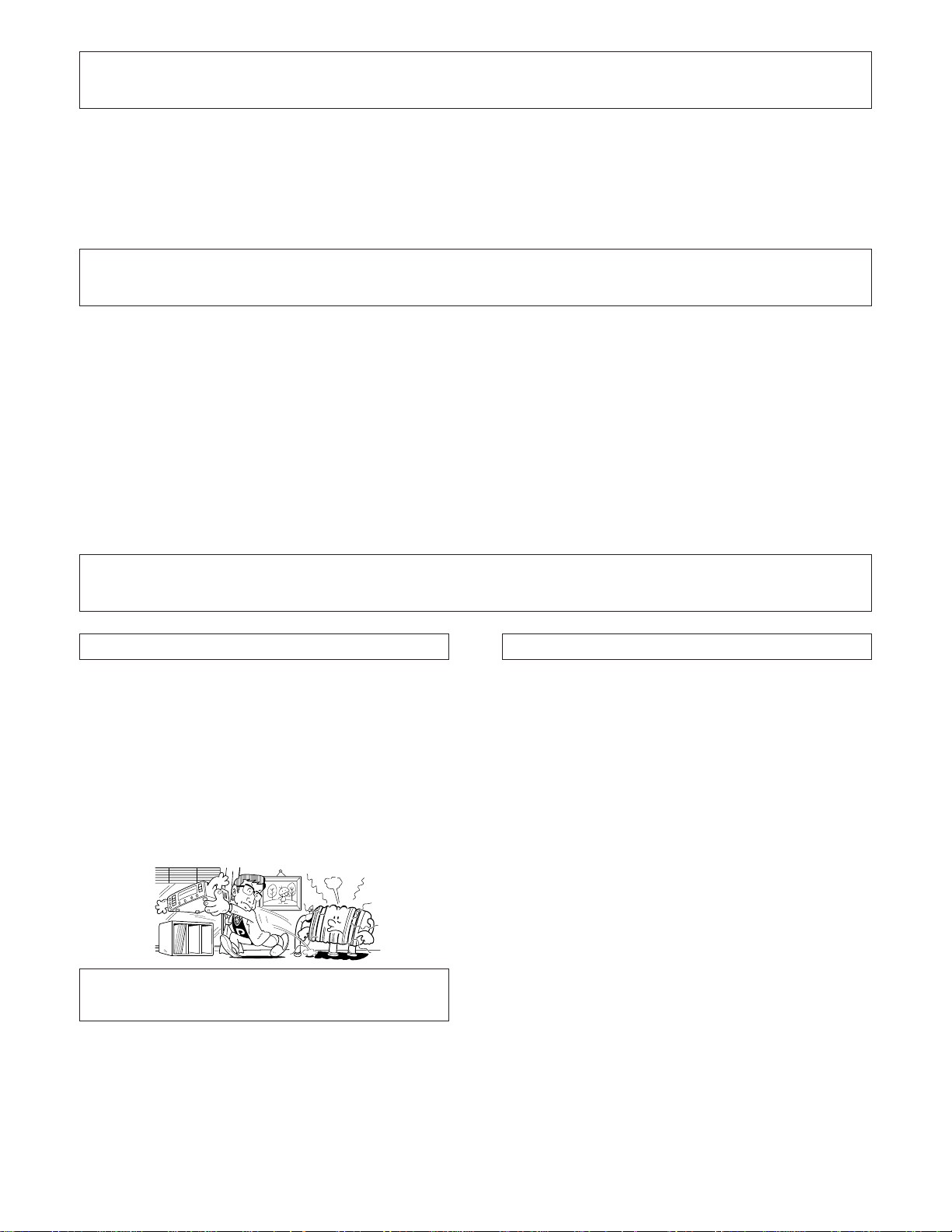
We Want You Listening For A Lifetime
Used wisely, your new sound equipment will provide a lifetime
of fun and enjoyment. Since hearing damage from loud noise is
often undetectable until it is too late, this manufacturer and the
Electronic Industries Association’s Consumer Electronics Group
recommend you avoid prolonged exposure to excessive noise. This
list of sound levels is included for your protection.
Decibel
Level Example
30 Quiet library, soft whispers
40 Living room, refrigerator, bedroom away from traffic
50 Light traffic, normal conversation, quiet office
60 Air conditioner at 20 feet, sewing machine
70 Vacuum cleaner, hair dryer, noisy restaurant
80 Average city traffic, garbage disposals, alarm clock
THE FOLLOWING NOISES CAN BE DANGEROUS
UNDER CONSTANT EXPOSURE
90 Subway, motorcycle, truck traffic, lawn mower
100 Garbage truck, chain saw, pneumatic drill
120 Rock band concert in front of speakers, thunderclap
140 Gunshot blast, jet plane
180 Rocket launching pad
Information courtesy of the Deafness Research Foundation.
T
C
E
L
E
•
A
N
O
R
S
S
C
I
EST 1924
O
C
I
N
A
I
at two feet.
D
U
S
T
R
I
E
S
•
N
O
I
T
Page 3
IMPORTANT SAFETY INSTRUCTIONS
READ INSTRUCTIONS — All the safety and operating
instructions should be read before the product is
operated.
RETAIN INSTRUCTIONS — The safety and operating
instructions should be retained for future reference.
HEED WARNINGS — All warnings on the product and
in the operating instructions should be adhered to.
FOLLOW INSTRUCTIONS — All operating and use
instructions should be followed.
CLEANING — Unplug this product from the wall outlet
before cleaning. The product should be cleaned only
with a polishing cloth or a soft dry cloth. Never clean
with furniture wax, benzine, insecticides or other
volatile liquids since they may corrode the cabinet.
ATTACHMENTS — Do not use attachments not
recommended by the product manufacturer as they
may cause hazards.
WATER AND MOISTURE — Do not use this product
near water — for example, near a bathtub, wash
bowl, kitchen sink, or laundry tub; in a wet basement;
or near a swimming pool; and the like.
ACCESSORIES — Do not place this product on an
unstable cart, stand, tripod, bracket, or table. The
product may fall, causing serious injury to a child or
adult, and serious damage to the product. Use only
with a cart, stand, tripod, bracket, or table
recommended by the manufacturer, or sold with
the product. Any mounting of the product should
follow the manufacturer’s instructions, and should
use a mounting accessory recommended by the
manufacturer.
CART — A product and cart combination should be
moved with care. Quick stops, excessive force, and
uneven surfaces may cause the product and cart
combination to overturn.
VENTILATION — Slots and openings in the cabinet are
provided for ventilation and to ensure reliable
operation of the product and to protect it from
overheating, and these openings must not be
blocked or covered. The openings should never be
blocked by placing the product on a bed, sofa, rug,
or other similar surface. This product should not be
placed in a built-in installation such as a bookcase or
rack unless proper ventilation is provided or the
manufacturer’s instructions have been adhered to.
POWER SOURCES — This product should be operated
only from the type of power source indicated on the
marking label. If you are not sure of the type of
power supply to your home, consult your product
dealer or local power company.
LOCATION – The appliance should be installed in a
stable location.
NONUSE PERIODS – The power cord of the appliance
should be unplugged from the outlet when left unused for a long period of time.
GROUNDING OR POLARIZATION
÷ If this product is equipped with a polarized alternating
current line plug (a plug having one blade wider than
the other), it will fit into the outlet only one way. This
is a safety feature. If you are unable to insert the plug
fully into the outlet, try reversing the plug. If the plug
should still fail to fit, contact your electrician to
replace your obsolete outlet. Do not defeat the
safety purpose of the polarized plug.
÷ If this product is equipped with a three-wire
grounding type plug, a plug having a third (grounding)
pin, it will only fit into a grounding type power outlet.
This is a safety feature. If you are unable to insert the
plug into the outlet, contact your electrician to
replace your obsolete outlet. Do not defeat the
safety purpose of the grounding type plug.
POWER-CORD PROTECTION — Power-supply cords
should be routed so that they are not likely to be
walked on or pinched by items placed upon or
against them, paying particular attention to cords at
plugs, convenience receptacles, and the point where
they exit from the product.
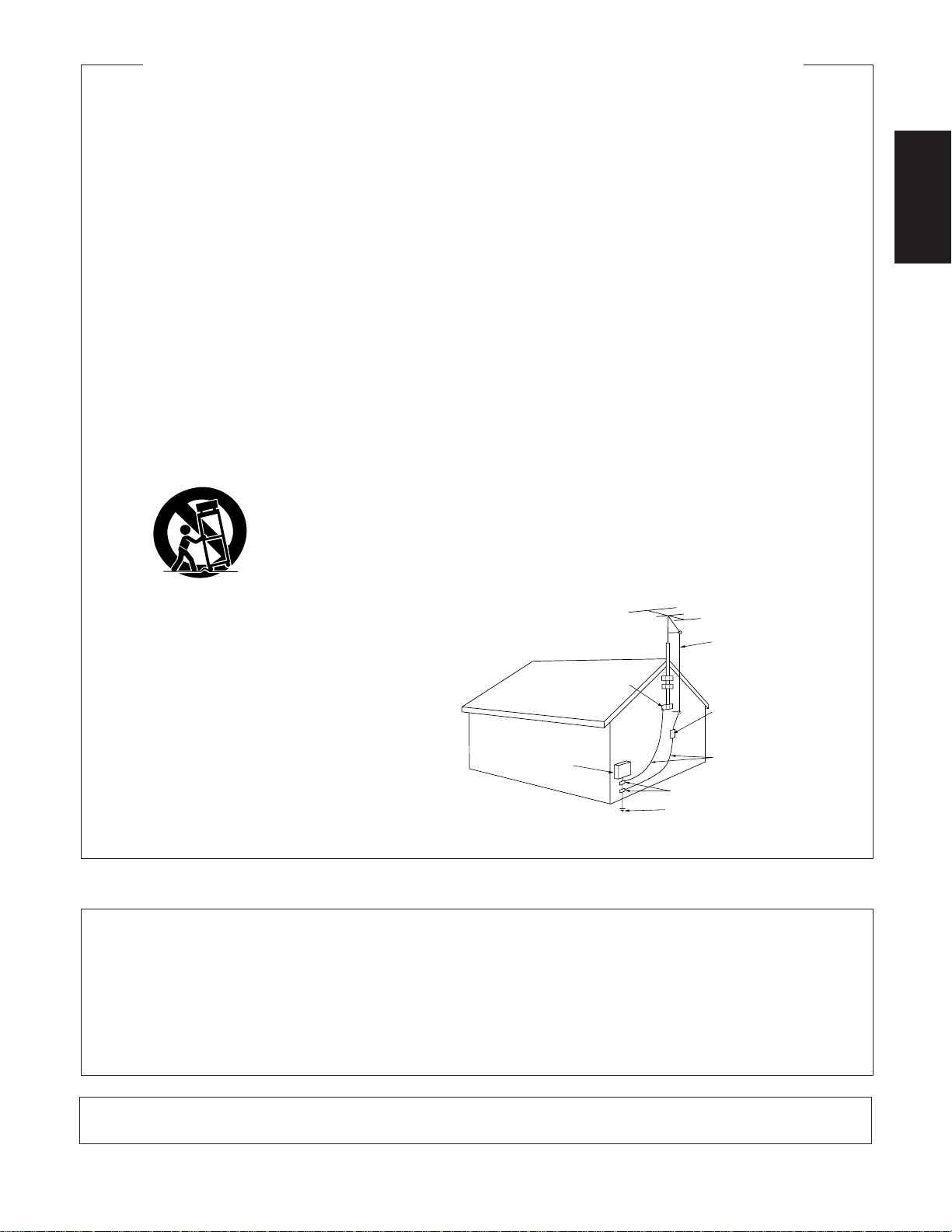
OUTDOOR ANTENNA GROUNDING — If an outside
antenna or cable system is connected to the product,
be sure the antenna or cable system is grounded so
as to provide some protection against voltage surges
and built-up static charges. Article 810 of the National
Electrical Code, ANSI/NFPA 70, provides information
with regard to proper grounding of the mast and
supporting structure, grounding of the lead-in wire
to an antenna discharge unit, size of grounding
conductors, location of antenna-discharge unit,
connection to grounding electrodes, and
requirements for the grounding electrode. See Figure
A.
LIGHTNING — For added protection for this product
during a lightning storm, or when it is left unattended
and unused for long periods of time, unplug it from
the wall outlet and disconnect the antenna or cable
system. This will prevent damage to the product
due to lightning and power-line surges.
POWER LINES — An outside antenna system should
not be located in the vicinity of overhead power lines
or other electric light or power circuits, or where it
can fall into such power lines or circuits. When
installing an outside antenna system, extreme care
should be taken to keep from touching such power
lines or circuits as contact with them might be fatal.
OVERLOADING — Do not overload wall outlets,
extension cords, or integral convenience receptacles
as this can result in a risk of fire or electric shock.
ELECTRIC
SERVICE
EQUIPMENT
Fig. A
OBJECT AND LIQUID ENTRY — Never push objects of
any kind into this product through openings as they
may touch dangerous voltage points or short-out
parts that could result in a fire or electric shock.
Never spill liquid of any kind on the product.
SERVICING — Do not attempt to service this product
yourself as opening or removing covers may expose
you to dangerous voltage or other hazards. Refer all
servicing to qualified service personnel.
DAMAGE REQUIRING SERVICE — Unplug this product
from the wall outlet and refer servicing to qualified
service personnel under the following conditions:
÷ When the power-supply cord or plug is damaged.
÷ If liquid has been spilled, or objects have fallen into
the product.
÷ If the product has been exposed to rain or water.
÷ If the product does not operate normally by following
the operating instructions. Adjust only those controls
that are covered by the operating instructions as an
improper adjustment of other controls may result in
damage and will often require extensive work by a
qualified technician to restore the product to its
normal operation.
÷ If the product has been dropped or damaged in any
way.
÷ When the product exhibits a distinct change in
performance — this indicates a need for service.
REPLACEMENT PARTS — When replacement parts
are required, be sure the service technician has used
replacement parts specified by the manufacturer or
have the same characteristics as the original part.
Unauthorized substitutions may result in fire, electric
shock, or other hazards.
SAFETY CHECK — Upon completion of any service or
repairs to this product, ask the service technician to
perform safety checks to determine that the product
is in proper operating condition.
WALL OR CEILING MOUNTING — The product should
not be mounted to a wall or ceiling.
HEAT — The product should be situated away from heat
sources such as radiators, heat registers, stoves, or
other products (including amplifiers) that produce
heat.
ANTENNA
LEAD IN
WIRE
GROUND
CLAMP
GROUND CLAMPS
POWER SERVICE GROUNDING
ELECTRODE SYSTEM
(NEC ART 250, PART H)
ANTENNA
DISCHARGE UNIT
(NEC SECTION 810-20)
GROUNDING CONDUCTORS
(NEC SECTION 810-21)
English
NOTE: This equipment has been tested and found to comply with the limits for a Class B digital device, pursuant to Part 15 of the FCC Rules.
These limits are designed to provide reasonable protection against harmful interference in a residential installation. This equipment
generates, uses, and can radiate radio frequency energy and, if not installed and used in accordance with the instructions, may cause harmful
interference to radio communications. However, there is no guarantee that interference will not occur in a particular installation. If this
equipment does cause harmful interference to radio or television reception, which can be determined by turning the equipment off and on,
the user is encouraged to try to correct the interference by one or more of the following measures:
– Reorient or relocate the receiving antenna.
– Increase the separation between the equipment and receiver.
– Connect the equipment into an outlet on a circuit different from that to which the receiver is connected.
– Consult the dealer or an experienced radio/TV technician for help.
Information to User
Alteration or modifications carried out without appropriate authorization may invalidate the user's right to operate the equipment.
<ARE7263>
3
En
Page 4
CONTENTS
FEATURES ......................................................................... 4
INSTALLATION .................................................................. 4
CONNECTIONS ................................................................. 5
PANEL FACILITIES ............................................................ 7
FEATURES
7 Advanced Direct Energy MOS Power Amp
Pioneer incorporates highest quality amp circuitry featuring Advanced Direct Energy MOS FET devices which can
achieve higher performance. Together with Pioneer’s original Wide Range Linear Circuit technology they reduce
power consumption while maintaining the power output of
current models.
In terms of performance, this technology contributes to flat
damping factor characteristics across the audio spectrum.
It also allows a wide range and especially ultra␣ high frequencies to be reproduced more accurately and improves
power linearity.
OPERATIONS .................................................................. 10
REMOTE CONTROL ........................................................ 11
TROUBLESHOOTING ...................................................... 12
SPECIFICATIONS ............................................................. 13
7 Low power consumption design
7 High-power Output:
60 W + 60 W/4 Ω (FTC)
(20 Hz-20 kHz, 0.3%)
7 Wide-Range Linear Circuit
This new current feedback circuit assures improved operating stability for flat output impedance and stable driving
of speakers across the full range of frequencies.
7 Silent microprocessor system
7 Stabilizer
Transformer stabilizer and stabilizer frame (attached to
chassis) deliver powerful sound.
INSTALLATION
LOCATION
Install the unit in a well ventilated location where it
will not be exposed to high temperature or humidity.
Do not install the unit in a location which is exposed to direct
rays of the sun, or near hot appliances or radiators. Excessive
heat can adversely affect the cabinet and internal components. Installation of the unit in a damp or dusty environment
may also result in a malfunction or an accident. (Avoid installation near cookers etc., where the unit may be exposed to oily
smoke, steam or heat.)
Do not install the unit on a tottered stand, nor on an unstable
or inclined surface.
MAINTENANCE OF EXTERNAL SURFACES
÷ Use a polishing cloth or dry cloth to wipe off dust and dirt.
÷ When the surfaces are dirty, wipe with a soft cloth dipped
in some neutral cleanser diluted five or six times with
water, and wrung out well, and then wipe again with a dry
cloth. Do not use furniture wax or cleaners.
÷ Never use thinners, benzine, insecticide sprays or other
chemicals on or near this unit, since these will corrode the
surfaces.
4
<ARE7263>
En
VENTILATION
÷ When installing this unit, make sure to leave space around
the unit for ventilation to improve heat radiation (at least 60
cm at top, 10 cm at rear, and 30 cm at each side). If not
enough space is provided between the unit and walls or
other equipment, heat will build up inside, interfering with
performance or causing malfunctions.
÷ Do not place on a thick carpet, bed, sofa or fabric having a
thick pile. Do not cover with fabric or other covering.
Anything that blocks ventilation will cause internal temperature to rise, which may lead to breakdown or fire
hazard.
POWER-CORD CAUTION
Handle the power cord by the plug. Do not pull out the plug by
tugging the cord and never touch the power cord when your
hands are wet as this could cause a short circuit or electric
shock. Do not place the unit, a piece of furniture, etc., on the
power cord, or pinch the cord. Never make a knot in the cord
or tie it with other cords. The power cords should be routed
such that they are not likely to be stepped on. A damaged
power cord can cause fire or give you an electrical shock.
Check the power cord once in a while. When you find it
damaged, ask your nearest PIONEER authorized service
center or your dealer for a replacement.
Page 5
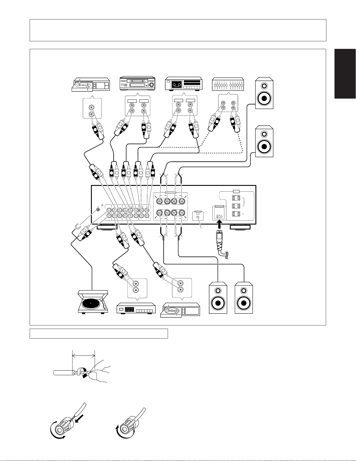
CONNECTIONS
Before making or changing the connections, switch off the power switch and disconnect the power cord
from the AC outlet.
OUT
CD
L
R
L
R
L
R
SIGNAL
GND
L
R
L
L
R
PHONOINTUNERINCDINLINE/
Cassette deck/
CD recorder/
MD recorder
MINIDISC
PLAY
REC
L
R
L
R
L
L
R
TAPE 2 MONITOR
L
R
OUT INOUT IN
R
SURROUND
R
L
BACK
IN
TAPE 1/CD-R/MD
REC PLAY REC PLAY
Cassette deckCD player
ª
R
SPEAKERS
RL
ª · · ª
R
REC
L
R
L
R
ª
·
·
B
A
L
PLAY
Adaptor component
(graphic equalizer, etc.)
IN
L
L
R
CONTROL
OUT
R
AC INLET
ATTENTION:
NE RELIEZ PAS
AL'APPAREIL
DE TELEVISION
OU AU MONITEUR.
OUT
L
R
R
OUTLETS
AC 120 V 60 Hz
L
AC
Speaker system B
CAUTION:
DO NOT CONNECT
TV SET OR MONITOR.
SWITCHED
TOTAL
100W MAX
UNSWITCHED
100W MAX
Right (R)
Left (L)
English
L
R
R
R
L
L
R
L
ª
L
R
L
R
OUT
FM-AM
Turntable
Tuner DVD player, VCR, etc.
CONNECTING THE SPEAKER CORDS
1. Strip off the vinyl covering and twist the tip of the
wire core.
2. Loosen the knob and insert the wire core into the
terminal hole.
3. Tighten the knob to fix the wire core in place.
10mm
Twist the wire core.
·
See page 6.
ª·
To an AC wall socket.
AUDIO OUT
Left (L)
L
R
DVD
Right (R)
Speaker system A
NOTE:
Do not allow any of the cord conductors to protrude from the
terminals or touch any other conductors. Malfunctioning or
breakdowns may occur when conductors come into contact
with each other.
Speaker Impedance
When speaker systems are connected to only SPEAKERS A
or SPEAKERS B terminals, such speakers should have rated
impedance in the range of 4–16 Ω.
When speaker are connected to both A and B terminals, they
should have a rated impedance in the range of 8 –32 Ω.
1
2
\
3
5
<ARE7263>
En
Page 6
CONNECTIONS
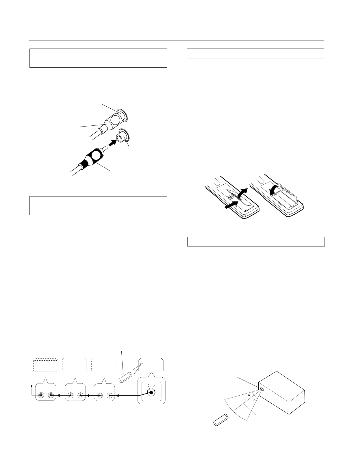
CONNECTING THE INPUT/OUTPUT
CORDS
Connect the white plug to the L (left) channel, and the red plug
to the R (right) channel. Be sure to push the plugs securely.
Left channel
L
White plug
Right channel
R
Red plug
REMOTE CONTROL CORD CONNECTIONS
LOADING BATTERIES
Open the battery compartment cover on the back of the
remote control unit.
Insert size AA/R6P dry cell batteries into the battery compartment in accordance with the indications (ª ,·) inside the
compartment.
Close the cover of the battery case.
Incorrect use of batteries may lead to leakage or
rupture. Always be sure to follow these guidelines:
1. Always insert batteries into the battery compartment correctly matching the positive ª and the negative · polari-
ties as indicated inside the compartment.
2. Never mix new and used batteries.
3. Batteries of the same size may have different voltages
depending on their type. Do not mix different types of
batteries.
·
ª
ª
·
By interconnecting the CONTROL jacks of Pioneer units with
the Î mark, the entire system can be operated with this
remote control unit, although some of the units (AM/FM
tuner, CD player, cassette deck, etc.) may not be equipped
with remote sensors. The entire system can be operated by
a remote control unit by connecting PIONEER stereo components to each other using the control input (CONTROL IN) jack
on each component. Use the remote control cord supplied
with the respective unit for the connection. An example is
shown in the figure. As long as you connect “OUT” to “IN”,
the connecting sequence is arbitrary. When a unit has only an
“IN” connector, however, connect it last.
NOTE:
When the POWER switch is set to OFF, the components
connected to the CONTROL OUT jack can not be operated
with the remote control unit.
Remote
control unit
A-35R
AM/FM
tuner
CONTROL
OUT IN
CD player
CONTROL
OUT IN
Cassette
deck
CONTROL
OUT IN
CONTROL
OUT
RANGE OF REMOTE CONTROL
When the remote control unit is pointed at the remote sensor
window on the stereo amplifier and any of its buttons is
pressed, the unit and other components can be operated by
remote control.
Distance : Within a range of approx. 7 meters from the unit’s
remote control sensor window.
Angle : Within approx. 30 degrees from the center of the
unit’s remote control sensor window.
Remote control will not be possible if there is an
obstacle between the remote control unit itself
and the unit’s remote control sensor window.
÷ The accessory remote control unit can be used to control
some functions of other Pioneer cassette decks, CD players and tuners (only those Pioneer components bearing
the Î mark).
Remote control
sensor window
30
30
6
<ARE7263>
En
m
7
Page 7
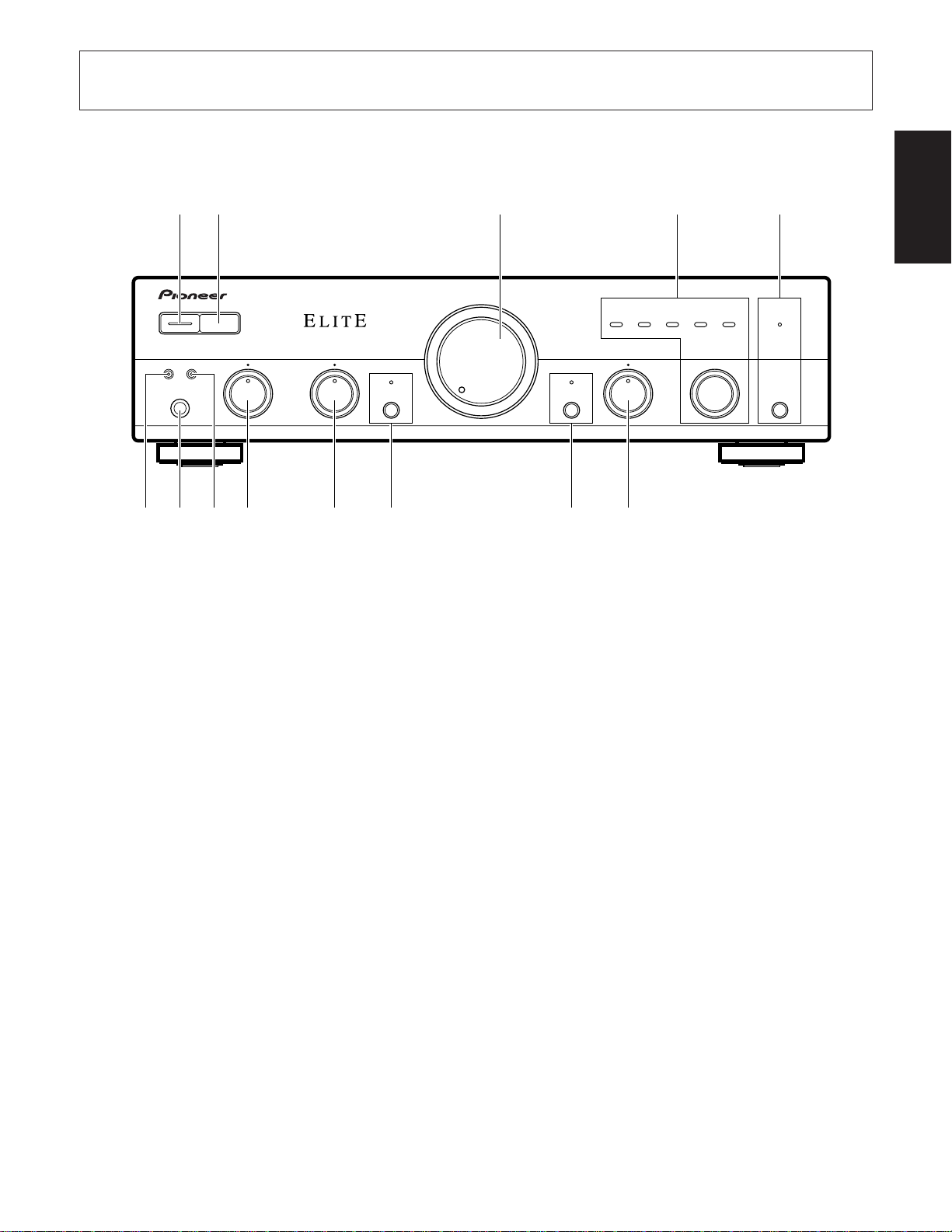
PANEL FACILITIES
[ FRONT PANEL ]
1345
2
POWER
OFF ON
—
A SPEAKERS B
PHONES
Î
_
~
STEREO AMPLIFIER
BASS
–
+
z¿≤.B
REFERENCE STEREO AMPLIFIER
TREBLE
–
+
VOLUME
SB MODE DIRECT
MIN MAX
CD
BALANCE
L
67890=-
TUNER
R
PHONO
LINE
TAPE 1/
CD-R/MD
SB
INPUT SELECTOR
TAPE 2
MONITOR
TAPE 2
MONITOR
Direct Energy MOS
English
1 POWER (— OFF/_ ON) switch
Press to turn power to the unit ON and OFF.
This unit cannot be turned ON and OFF using the remote
control unit.
2 REMOTE CONTROL SENSOR window
3 VOLUME control
Use to adjust the volume level.
4 INPUT SELECTOR knob/indicators
Turn the knob clockwise or counterclockwise so that the
indicator lights for your desired input source. Turning the knob
clockwise causes the lit indicator to right. Turning counterclockwise causes it to left.
CD : For compact disc playback with a CD player.
TUNER : For AM or FM broadcast reception with a
tuner.
PHONO : For record playback with a turntable.
LINE/SB : Set to this position when listening to the
program from a component connected to the
LINE/SURROUND BACK terminals.
TAPE 1/ : For playback with a cassette deck, CD
CD-R/MD recorder or MD recorder connected to TAPE1/
CD-R/MD terminals.
5 TAPE 2 MONITOR button/indicator
Use when there is an adaptor component (graphic equalizer,
etc.) or cassette deck connected to the TAPE2 MONITOR
terminals.
On : Indicator lights when using the adaptor component or
listening to the cassette deck.
Off : Indicator goes off when not in use.
NOTES:
÷
When no connections are made to the TAPE2 MONITOR
terminals, or when they are not in use, be sure to set this
switch to the off position. (No sound will be heard if it is set
to the on position.)
÷
When the TAPE2 MONITOR indicator is on and the INPUT
SELECTOR knob is not set to TAPE1/CD-R/MD, the signals
which are input through TAPE 2 MONITOR are then output
at TAPE1/CD-R/MD REC OUT.
6 BALANCE control
Should normally be left in the center position. Adjust balance
if the sound is louder from one of the speakers. If the right side
is louder, turn toward the L (left) position and if the left side is
louder, turn toward the R (right) position.
NOTE:
This control does not operate when the DIRECT button is in
the on position.
<ARE7263>
En
7
Page 8

PANEL FACILITIES
7 DIRECT button/indicator
Use this button when you do not wish to pass the output from
input terminal equipment through the various frequency
adjusting circuits (BASS, TREBLE, BALANCE, LOUDNESS).
On : The indicator lights: The signals passing through the
input terminals are reproduced without passing through
the various frequency adjusting circuits. This results in
flat, pure sound which is a more faithful reproduction of
the input source.
Off : The indicator goes off: The signal passes through the
various frequency adjusting circuits.
8 SB MODE button/indicator
The SB mode is a special mode in which the amplifier does not
accept remote control (But all of the facilities can be controled
by manual as same as SB mode OFF.). Fix the VOLUME
control near the center position. In this mode, the set can be
used as a power amplifier which amplifies the LINE/SURROUND BACK input (the function name is LINE/SB) with a
input sensitivity of 1 V.
For example, when the set is combined with one of Pioneer’s
Surround Back compatible receiver, the set can be used as
the Surround Back amplifier (For details, please refer to the
instruction manual of the receiver.)
9 TREBLE tone control
Use to adjust the high-frequency tone. The center position is
the flat (normal) position. When turned to the right, highfrequency tones are emphasized; when turned to the left,
high-frequency tones are de-emphasized.
NOTE:
This control does not operate when the DIRECT button is in
the on position.
0 BASS tone control
Use to adjust the low-frequency tone. The center position is
the flat (normal) position. When turned to the right, lowfrequency tones are emphasized; when turned to the left,
low-frequency tones are de-emphasized.
NOTE:
This control does not operate when the DIRECT button is in
the on position.
- SPEAKERS B (ON/OFF) button/indicator
Use this button to listen to the speaker system connected to
SPEAKERS B terminals.
ON : The indicator lights. Sound is heard from the speaker
system.
OFF : The indicator goes off. No sound is heard from the
speaker system. Set to this position when listening
with headphones.
= PHONES jack
When using headphones, insert the plug into this jack.
NOTE:
The speakers continue to output sound even when headphones are plugged into this jack.
To mute the sound from the speakers, press the SPEAKERS
button to OFF.
~ SPEAKERS A (ON/OFF) button/indicator
Use this button to listen to the speaker system connected to
SPEAKERS A terminals.
ON : The indicator lights. Sound is heard from the speaker
system.
OFF : The indicator goes off. No sound is heard from the
speaker system. Set to this position when listening
with headphones.
8
<ARE7263>
En
Page 9

PANEL FACILITIES
[ REAR PANEL ]
1 0 -
SIGNAL
1 GND (Turntable ground) terminal
2 PHONO terminals
3 TUNER terminals
4 CD terminals
5 LINE/SURROUND BACK terminals
2 3 4 65 7 8 9
GND
PHONOINTUNERINCDINLINE/
L
R
SURROUND
BACK
IN
TAPE 1/CD-R/MD
REC PLAY REC PLAY
TAPE 2 MONITOR
OUT INOUT IN
L
R
SPEAKERS
RL
B
ª · · ª
R
A
L
@ AC INLET jack
Connect power cord to here and an AC wall socket, or the AC
outlet of an audio timer.
If you are going to be away from home for a long period of
time, disconnect the unit from the wall socket.
NOTES:
÷
÷
AC
OUTLETS
AC 120 V 60 Hz
#
CAUTION:
DO NOT CONNECT
TV SET OR MONITOR.
SWITCHED
TOTAL
100W MAX
UNSWITCHED
100W MAX
AC INLET
CONTROL
OUT
!~= @
ATTENTION:
NE RELIEZ PAS
AL'APPAREIL
DE TELEVISION
OU AU MONITEUR.
If you use an other power cord than provided, we cannot
assume the liabilities in what may occur as a result of it.
(The provided power cord has a current capacity of 7 A.)
English
6 TAPE 1/CD-R/MD REC (OUT) terminals
7 TAPE 1/CD-R/MD PLAY (IN) terminals
8 TAPE 2 MONITOR REC (OUT) terminals
9 TAPE 2 MONITOR PLAY (IN) terminals
0 SPEAKERS B terminals (Right channel)
- SPEAKERS B terminals (Left channel)
= SPEAKERS A terminals (Right channel)
~ SPEAKERS A terminals (Left channel)
! CONTROL OUT jack (see page 6)
This jack is for output of control signals when operating other
components bearing the Î mark with the attached remote
control unit.
# AC OUTLETS
[SWITCHED TOTAL 100 W MAX]
Power supplied through these outlets is turned on and off by the
amplifier’s POWER ON/OFF switch. Total electrical power consumption of connected equipment should not exceed 100 W.
[UNSWITCHED 100 W MAX]
Power flows continually to this outlet, regardless of whether the
amplifier is switched ON or OFF. Electrical power consumption of
the connected equipment should not exceed 100 W.
NOTES:
• Do not connect appliances with high power consumption
such as heaters, irons, or television sets to the AC OUTLETS in order to avoid overheating or fire risk. This can
cause the amplifier to malfunction.
• The equipment should be disconnected by removing the
mains plug from the wall socket when not in regular use,
e.g. when on vacation.
9
<ARE7263>
En
Page 10

OPERATIONS
BEFORE BEGINNING OPERATIONS
1. Set the VOLUME control to minimum.
2. Set the POWER switch to ON.
3. Press the SPEAKERS button corresponding to
the speaker system to be used.
4. Set the BALANCE control to the center position.
5. Set the DIRECT button to off.
6. Set the TAPE2 MONITOR button to off.
PLAYBACK PROCEDURES
1. Set the INPUT SELECTOR knob to the desired
playback source.
÷ For playback of a compact disc: Set to [CD].
÷ For reception of an AM/FM broadcast: Set to [TUNER].
÷ For playback of a record: Set to [PHONO].
÷ For playback with the equipment connected to LINE/
SURROUND BACK terminals: Set to [LINE/SB].
÷ For playback of a tape: Set to [TAPE1/CD-R/MD].
NOTES:
÷
When you do not want to monitor the TAPE2 MONITOR
sound, set the TAPE2 MONITOR button to OFF.
÷
When you select PHONO, the sound is muted for a few
seconds.
2. Operate the equipment to begin playback.
3. Adjust playback volume with VOLUME control
on this unit.
4. Adjust the tone to your preference using the
BASS and TREBLE controls.
RECORDING TAPES
1. Select the recording equipment with the INPUT
SELECTOR knob.
2. Begin recording by operating the recording equip-
ment and cassette deck.
Refer to the operating instructions of your cassette deck
for proper operating procedures.
COPYING TAPES
When two decks are used, you can record the sounds from
one deck onto the other.
1. Load tapes for playback (pre-recorded tape) and
recording (blank tape) into the respective cassette decks.
2. Select the copying direction with the INPUT SELECTOR knob and TAPE2 MONITOR button.
÷ When copying from the cassette deck of TAPE1/CD-R/
MD terminals to the cassette deck of the TAPE2 MONITOR terminals: Set the INPUT SELECTOR knob to
TAPE1/CD-R/MD.
÷ When copying from the cassette deck of TAPE2 MONI-
TOR terminals to the cassette deck of TAPE1/CD-R/MD
terminals: Set the TAPE2 MONITOR button to ON and
the INPUT SELECTOR knob to a position other than
TAPE1/CD-R/MD.
3. Operate the cassette decks to begin copying.
Set the cassette deck with the original (playback) tape to
the playback mode, and set the cassette deck with the
blank tape to the recording mode.
TO USE THE COMPONENT CONNECTED
TO THE TAPE2 MONITOR TERMINALS
[For a cassette deck]
÷ A cassette deck connected here can be operated in the
same way (recording and playback) as a deck connected to
the TAPE2 MONITOR terminals.
÷ Also, if two decks are used, you can copy tapes from one
deck onto the other (see the section “COPYING TAPES”).
1. Set the TAPE2 MONITOR button to ON.
2. Operate the cassette deck to perform playback
(or recording).
NOTE:
The source selected with the INPUT SELECTOR knob is
backed up for a few days even when the POWER switch is set
to off or the power cord is unpluged.
After this period, the CD is automatically selected when the
power is supplied.
[For an adaptor component]
By connecting a graphic equalizer, source sounds (from discs,
tapes, AM/FM broadcasts, etc.) can be heard with added sound
and tone compensation.
Sounds compensated with the adaptor component can be
recorded on the cassette deck connected to the TAPE1/CD-R/
MD terminals.
Application examples:
÷ To make a tape copy with contents identical to the original
tape.
÷ To edit a recording of an FM broadcast in order to cut out
unwanted commercials, recording only of desired material
onto another tape.
10
<ARE7263>
En
1. Set the TAPE2 MONITOR button to ON.
2. Play back the source.
3. Operate the adaptor component.
NOTE:
Be sure to perform this operation with the adaptor component
power switch in the on position. Even when not using the
adaptor component, its power switch must be left on. If the
adaptor component is switched off, no sound will be produced, or the playback sound will be distorted.
Page 11

REMOTE CONTROL
English
1 CD POWER button
Switches CD player power ON/OFF.
1
2
3
4
5
6
STANDBY/ON
CD TUNER TAPE
TAPE
2
SELECT
TAPE
1¡
DECK ΙΙ
DECK
Ι
CD
4¢73
DISC
SELECT
CD TUNER PHONO
TAPE 1 TAPE 2 LINE
STEREO AMPLIFIER
REMOTE CONTROL UNIT
7
–+
STATION
TUNER
VOLUME
7 TUNER POWER button
Switches TUNER power ON/OFF.
7
3
8
9
0
+
-
=
–
Î
2 TAPE SELECT button
Selects the cassette No. (1 to 6) for multi-cassette changer.
3 DECK II button
To operate Deck II, press this button before pressing the
operating buttons. Also, when using a single deck, press this
button before pressing the operating buttons.
4 DECK I button
To operate Deck I, press this button before pressing the
operating buttons.
5 DISC SELECT button
Press this to select discs on a multi or twin tray compact disc
player.
6 Input selector button
Use to select the playback source.
CD : For compact disc playback with a CD player.
TUNER : For AM or FM broadcast reception with a tuner.
PHONO : For record playback with a turntable.
TAPE 1 : For playback with a cassette deck,CD recorder or
MD recorder connected to TAPE1/CD-R/MD terminals.
TAPE 2 : For playback with a cassette deck or adaptor con-
nected to TAPE 2 MONITOR terminals.
LINE : For playback with a component connected to the
LINE/SURROUND BACK terminal.
8 TAPE POWER button
Switches the cassette deck power ON/OFF.
(Can not turn ON/OFF some cassette decks.)
9 TAPE operation buttons
2, 3 : Playback in the direction of the arrows.
7 : Stop
1, ¡ : Tape fast forward/reverse.
0 CD player operation buttons
4 : Returns you to the start of the current track.
(Track search)
¢ : Takes you to the start of the next track.
(Track search)
7 : Stop
3 : Play
- STATION + (up), – (down) buttons
Calls each station number in sequence.
= VOLUME + (up), – (down) buttons
+ ....................................................... Increases the volume.
– ..................................................... Decreases the volume.
NOTE:
When the accessory remote control unit is used to operate
Î
other Pioneer components with the
used to operate functions which do not correspond to the
functions listed on the remote control unit.
mark, it cannot be
11
<ARE7263>
En
Page 12

TROUBLESHOOTING
Incorrect operations are often mistaken for trouble and malfunctions. If you think that there is something wrong with this component,
check the points below. Sometimes the trouble may lie in another component. Investigate the other components and electrical
appliances being used.
If the trouble cannot be rectified even after exercising the checks listed below, ask your nearest PIONEER authorized service center
or your dealer to carry out repair work.
Symptom
No power supplied to unit.
No sound.
No sound from one speaker.
Cause
÷ Power plug is disconnected from outlet.
÷ The amplifier’s power plug has been
plugged into another component power
outlet (e.g. timer, etc.) but power to that
unit is disconnected.
÷ The AC INLET plug is disconnected.
÷ Connecting cords are disconnected from
terminals, or connected incorrectly.
÷ Terminals, or connecting cords pin plugs
are dirty.
÷ The TAPE2 MONITOR button is set to ON
(except when using an adaptor component).
÷ Operation of other components is incor-
rect.
÷ The position of the INPUT SELECTOR does
not match the component to be played
back.
÷ Both SPEAKERS selector buttons are set
to OFF.
÷ Connecting cords or speaker cords are
disconnected on that side.
÷ BALANCE control is set to one side.
Remedy
÷ Insert plug securely into outlet.
÷ Turn on power to other component.
÷ Insert the AC INLET plug securely till the
bottom of the jack.
÷ Connect securely.
÷ Clean terminals and plugs.
÷ Set the TAPE2 MONITOR button to OFF.
÷ Consult the operating instructions for the
other components.
÷ Set the button correctly (CD, TUNER,
PHONO,LINE/SB,TAPE1/CD-R/MD).
÷ Set one button or both buttons to ON.
÷ Connect securely.
÷ Set BALANCE control to center position.
Cannot record tapes.
Cannot perform tape copying.
The remote control unit does
not work. (Other components
cannot be operated.)
÷
Abnormal functioning of this unit may be caused by static electricity, or other external interference. To restore normal operation,
÷ Connections are incorrect.
÷ Operation of cassette deck is incorrect.
÷ The TAPE2 MONITOR button is set to ON.
÷ The position of the INPUT SELECTOR knob
and TAPE2 MONITOR button are incorrect
(when using 2 cassette decks).
÷ Operation of cassette decks is incorrect.
÷ Batteries are dead or no batteries in re-
mote control unit.
÷ The remote control sensor is not receiving
any signals.
÷ The remote control cord is not connected
correctly.
÷ A fluorescent light is shining on the remote
sensor window.
÷ SB MODE is set to ON.
÷ Reconnect properly.
÷ Consult the operating instructions for the
cassette deck.
÷ Set the TAPE2 MONITOR button to OFF.
÷ Set buttons correctly (See section COPY-
ING TAPES).
÷ Consult the operating instructions for the
cassette decks.
÷ Insert new batteries (see page 6).
÷ Operate the remote control unit within a
range of 7 meters and an angle of 30
degrees (refer to page 6).
÷ Connect correctly (see page 6).
÷ Move so fluorescent light does not shine
directly on amplifier’s front panel remote
sensor window.
÷ Switch it OFF (see page 8).
turn the power off and then on again, or unplug the AC power cord and then plug it in again.
12
<ARE7263>
En
Page 13

SPECIFICATIONS
Amplifier Section
Continuous rated power output of 60 watts* per
channel, min., at 4 ohms, from 20 Hz to 20,000 Hz
with no more than 0.3 %** total harmonic distortion.
Input sensitivity/impedance
PHONO (MM) ........................................... 2.8 mV/50 kΩ
CD, TUNER, LINE/SB, TAPE1/CD-R/MD, TAPE2 MONITOR
.................................................................. 200 mV/50 kΩ
PHONO (MM) overload level
1 kHz, T.H.D. 0.1 % ............................................ 150 mV
Output level/impedance
TAPE1 REC, TAPE2 MONITOR REC ......... 200 mV/1 kΩ
Frequency response
PHONO (MM) .......................... 20 Hz to 20 kHz, ±0.5 dB
CD, TUNER, LINE/SB, TAPE1/CD-R/MD, TAPE2 MONITOR
................................................ 5 Hz to 100 kHz,
Tone control
BASS ...................................................... ±8 dB (100 Hz)
TREBLE ................................................... ±8 dB (10 kHz)
Loudness contour (volume control set at –30 dB position)
........................................ +6 dB (100 Hz)/+4 dB (10 kHz)
Signal-to-Noise ratio (IHF short circuit, A network)
PHONO (MM, 5 mV input) ............................. 85 dB***
CD, TUNER, LINE/SB, TAPE1/CD-R/MD, TAPE2 MONITOR
....................................................................... 106 dB***
+0
dB***
–3
Power Supply/Miscellaneous
Power requirements ................................. AC 120 V, 60 Hz
Power consumption ................................................... 145 W
Dimensions (including knobs and other protruding parts)
.......................................420 (W) x 114 (H) x 307 (D) mm
Weight (without package) ........................................... 5.9 kg
Accessories
Remote control unit ........................................................... 1
Batteries (AA/R6P) ............................................................. 2
Power cord (Rated current 7 A) ......................................... 1
Operating instructions........................................................ 1
Warranty card..................................................................... 1
NOTE:
Specifications and design are subject to possible modifications without notice, due to improvements.
* Measured pursuant to the Federal Trade Commission’s
Trade Regulation rule on Power Output Claims for Ampli-
fiers.
** Measured by Audio Spectrum Analyzer.
*** Measured with DIRECT button set to on.
English
Published by Pioneer Corporation.
Copyright © 2000 Pioneer Corporation.
All rights reserved.
13
<ARE7263>
En
Page 14

TABLE DES MATIERES
CARACTERISTIQUES....................................................... 14
INSTALLATION ................................................................ 14
CONNEXIONS.................................................................. 15
ELEMENTS DES PANNEAUX .......................................... 17
CARACTERISTIQUES
7 Amplificateur de puissance MOS à énergie directe
avancé
Pioneer incorpore des circuits d’amplification de haute
qualité dans des dispositifs MOS FET à énergie directe
avancés et capables d’atteindre des performances
optimales. Combinés à la technologie de circuit linéaire à
plage étendue, une exclusivité de Pioneer, ceux-ci réduisent
la consommation électrique tout en conservant la puissance de sortie des modèles actuels.
En termes de performances, cette technologie contribue à
obtenir un facteur d’amortissement plat sur le spectre
audio. Elle permet aussi de reproduire une large gamme de
fréquences, et plus particulièrement les fréquences les
plus hautes, avec davantage de précision tout en améliorant
la linéarité de la puissance.
UTILISATION ................................................................... 20
TELECOMMANDE ........................................................... 21
DEPISTAGE DES PANNES .............................................. 22
SPECIFICATIONS ............................................................. 23
7 Conception à faible consommation d’énergie
7 Sorties de haute puissance
60 W + 60 W/4 Ω (FTC)
(20 Hz-20 kHz, 0.3 %)
7 Circuit linéaire large gamme
Ce nouveau circuit à rétroaction de courant assure une
meilleure stabilité de fonctionnement pour une impédance
de sortie plate et un entraînement stable des enceintes sur
toute la gamme des fréquences.
7 Système silencieux à microprocesseur.
7 Stabilisateur
Le stabilisateur du transformateur ainsi que le boîtier du
stabilisateur (fixé au châssis) fournissent un son ultrapuissant.
INSTALLATION
EMPLACEMENT
Installer l’unité dans un endroit bien ventilé à l’abri
d’une température ou d’une humidité élevée.
Ne pas installer l’unité dans un endroit directement exposé
aux rayons du soleil ou à proximité d’appareils de chauffage ou
de radiateurs. Une chaleur excessive peut avoir des
conséquences néfastes pour le coffret et les composants
internes. L’installation de l’unité dans un local humide ou
poussiéreux pourrait provoquer un fonctionnement défectueux
ou un accident. (Eviter également de l’installer près de
cuisinières, etc., où l’unité pourrait être exposée à des
émanations de fumée graisseuse, de vapeur ou de chaleur.)
Ne pas installer l’amplificateur sur une surface instable ou
inclinée.
ENTRETIEN DES SURFACES
EXTERIEURES
÷ Se servir d’un linge à polir ou d’un chiffon sec pour enlever
la poussière ou les souillures.
÷ Si les surfaces sont très sales, les frotter avec un linge doux
trempé dans un détergent neutre, dilué dans cinq ou six
fois son volume d’eau, puis essuyer convenablement les
surfaces. Ne pas utiliser de cire ou de produit pour meubles.
÷ Ne jamais utiliser de diluant pour peinture, de benzine ou
d’insecticide en atomiseur sur ou à proximité de l’appareil,
car ses surfaces en seraient endommagées.
14
<ARE7263>
Fr
VENTILATION
÷ Lors de l’installation de cet appareil, veillez à ménager un
espace suffisant autour de ses parois de manière que la
chaleur puisse se dissiper aisément (au moins 60 cm à l
apartie supérieure, 10 cm à l’arrière et 30 cm de chaque
côté). Si l’appareil est trop près d’un mur, d’une cloison ou
d’autres appareils, sa température interne peut s’élever
anormalement, ce qui entraîne un dégradation de ses
performances et des anomalies de fonctionnement.
÷ Ne placez pas l’appareil sur un tapis épais, un lit, un sofa ou
un tissu à fibres longues. Ne le couvrez pas d’un vêtement
ou de tout autre matériau.
Tout ce qui peut empêcher la libre circulation de l’air
provoque une augmentation de la température intérieure,
ce qui peut conduire à une anomalie de fonctionnement ou
à un incendie.
NOTE IMPORTANTE SUR LE CABLE
D’ALIMENTATION
Tenir le câble d’alimentation par la fiche. Ne pas débrancher
la prise en tirant sur le câble et ne pas toucher le câble avec
les mains mouillées. Cela risque de provoquer un court-circuit
ou un choc électrique. Ne pas poser l’appareil ou un meuble
sur le câble. Ne pas pincer le câble. Ne pas faire de noeud avec
le câble ou l’attacher à d’autres câbles. Les câbles
d’alimentation doivent être posés de façon à ne pas être
écrasés. Un câble abîmé peut provoquer un risque d’incendie
ou un choc électrique. Vérifier le câble d’alimentation de
temps en temps. Contacter le service après-vente PIONEER
le plus proche ou le revendeur pour un remplacement.
Page 15

CONNEXIONS
Avant d’effectuer les raccordement, ou de les modifier, veillez à couper l’alimentation et à débrancher la fiche du
cordon d’alimentation.
OUT
CD
L
R
R
R
SIGNAL
GND
Platine à cassette/
enregistreur CD/
enregistreur MD
L
L
L
R
PHONOINTUNERINCDINLINE/
L
R
L
R
SURROUND
REC
R
L
TAPE 1/CD-R/MD
REC PLAY REC PLAY
BACK
IN
Composant adaptateur
(égaliseur graphique, etc.)Platine à cassetteLecteur CD
MINIDISC
IN
PLAY
PLAY
L
R
L
R
REC
L
R
L
L
R
L
R
OUT
L
R
L
R
R
Système d’enceintes
Droit (R)
Gauche (L)
ª
·
ª
R
ª · · ª
L
R
·
SPEAKERS
RL
B
R
A
L
CONTROL
AC
OUTLETS
AC 120 V 60 Hz
CAUTION:
DO NOT CONNECT
TV SET OR MONITOR.
SWITCHED
TOTAL
100W MAX
UNSWITCHED
100W MAX
ATTENTION:
NE RELIEZ PAS
AL'APPAREIL
DE TELEVISION
OU AU MONITEUR.
AC INLET
OUT
L
L
R
TAPE 2 MONITOR
OUT INOUT IN
Français
L
R
R
R
L
L
R
L
ª
L
R
L
R
OUT
FM-AM
Table de lecture
Tuner
Lecteur DVD, magnétoscope
à cassette, etc.
CONNEXION DES CORDONS D’ENCEINTES
1. Retirer la garniture en vinyle et torsader l’extrémité de
l’âme du câble.
10mm
Torsader l’âme du
câble.
2. Desserrer le bouton et insérer l’âme dans le trou
de borne.
3. Serrer le bouton pour fixer l’âme en place.
2
1
\
3
·
Voir page 17.
ª·
Vers prise secteur.
AUDIO OUT
L
R
Gauche
(L)
DVD
Droit (R)
Système d’enceintes A
REMARQUE:
Ne pas laisser l’un des conducteurs du cordon dépasser des
bornes ou toucher d’autres conducteurs. Un fonctionnement
défectueux ou des pannes peuvent se produirent lorsque les
conducteurs entrent en contact les uns avec les autres.
Impédance des enceintes
Lorsqu’un systéme d’enceintes est raccordé seulement aux
bornes SPEAKERS A ou SPEAKERS B, les enceintes doivent
avoir une impédance nominale de 4 à 16 Ω.
Lorsque des systéme d’enceintes sont raccordés à la fois aux
bornes SPEAKERS A et B, les enceintes doivent avoir une
impédance nominale de 8 à 32 Ω.
15
<ARE7263>
Fr
Page 16

CONNEXIONS
CONNEXION DES CORDONS
D’ENTREE/SORTIE
Connecter la fiche blanche au canal L (gauche) , et la fiche
rouge au canal R (droit) . S’assurer de bien insérer les fiches
à fond.
Canal gauche
L
Fiche blanche
Canal droit
R
Fiche rouge
CONNEXIONS DU CORDON DE
TELECOMMANDE
CHARGEMENT DES PILES
Ouvrir le couvercle du compartiment des piles au dos de
l’unité de télécommande.
Insérer des piles de format AA/R6P dans le compartiment des
piles conformément aux indications (ª , ·) se trouvant à
l’intérieur du compartiment.
Fermer le couvercle du compartiment des piles.
Une utilisation incorrecte des piles peut conduire à
des fuites ou une rupture. Toujours suivre ces
conseils:
1. Toujours insérer correctement les piles dans le
compartiment des piles en respectant les polarités positive
ª et négative · indiquées à l’intérieur du compartiment.
2. Ne jamais mélanger des piles usées et neuves.
3. Des piles de la même taille peuvent avoir des tensions
différentes en fonction de leur type. Ne pas mélanger des
types de pile différents.
·
ª
ª
·
En interconnectant les jacks CONTROL d’unités Pioneer
portant la marque Î, tout le système peut être commandé
avec cette unité de télécommande, bien que certaines des
unités (tuner AM/FM, lecteur CD, platine cassette, etc.)
puissent ne pas être équipées de détecteur de télécommande.
Tout le système peut être utilisé avec une unité de
télécommande en connectant les composants stéréo PIONEER les uns aux autres en utilisant le jack d’entrée de
commande (CONTROL IN) de chaque composant. Utiliser le
cordon de télécommande fourni avec les unités respectives
pour la connexion. Un exemple est indiqué sur la figure. Tant
que l’on connecte “OUT” à “IN”, la séquence de connexion
est arbitraire. Si une unité ne possède qu’un jack “IN”, la
connecter toutefois en dernier.
REMARQUE:
Quand l’interrupteur POWER est réglé sur OFF, les
composants reccordés à la prise CONTROL OUT ne peuvent
pas être contrôlés par la télécommande.
Unité de télécommande
A-35R
AM/FM
tuner
CONTROL
OUT IN
CD player
CONTROL
OUT IN
Cassette
deck
CONTROL
OUT IN
CONTROL
OUT
PORTEE DE LA TELECOMMANDE
Lorsque l’unité de télécommande est dirigée vers la fenêtre
du détecteur de télécommande sur l’amplificateur stéréo et
que l’une de ses touches est enfoncée, l’unité et les autres
composants peuvent être commandés par télécommande.
Distance : Dans les limites d’une portée d’environ 7
mètres de la fenêtre du détecteur de
télécommande.
Angle : Dans les limites d’environ 30 degrés depuis le
centre de la fenêtre du détecteur de
télécommande.
La télécommande ne sera pas possible s’il y a un
obstacle entre l’unité de télécommande et la
fenêtre du détecteur de télécommande.
÷ L’unité de télécommande accessoire peut être utilisée
pour contrôler certaines fonctions d’autres platines cassettes, lecteurs de CD et tuners (seulement ceux portant
la marque Pioneer Î).
Fenêtre du détecteur
de télécommande
16
<ARE7263>
Fr
30
30
m
7
Page 17

ELEMENTS DES PANNEAUX
[ PANNEAU AVANT ]
1345
2
POWER
OFF ON
_
—
A SPEAKERS B
STEREO AMPLIFIER
Î
BASS
z¿≤.B
REFERENCE STEREO AMPLIFIER
TREBLE
VOLUME
CD
BALANCE
TUNER
PHONO
LINE
TAPE 1/
CD-R/MD
SB
INPUT SELECTOR
TAPE 2
MONITOR
Français
PHONES
–
+
–
SB MODE DIRECT
+
~
1 Interrupteur POWER (— OFF/_ ON)
Appuyer sur cet interrupteur pour mettre l’appareil sous
tension ou hors tension.
La télécommande ne permet pas de mettre l’appareil sous
tension ou hors tension.
2 Fenêtre du détecteur de télécommande
3 Commande de volume (VOLUME)
Utilisée pour régler le niveau de volume.
4 Bouton/indicateurs SELECTEUR D’ENTREE (in-
put selector)
Tournez le bouton dans le sens des aiguilles d’une montre ou
dans le sens inverse afin d’allumer l’indicateur de la source
d’entrée de votre choix. L’indicateur de droite s’allume lorsque
vous tournez le bouton dans le sens des aiguilles d’une
montre. L’indicateur de gauche s’allume lorsque vous tournez
le bouton dans le sens inverse des aiguilles d’une montre.
CD : Pour une reproduction de compact disc avec
un lecteur CD.
TUNER : Pour une réception d’émission AM ou FM
avec un tuner.
PHONO : Pour une reproduction de disque avec une
table de lecture.
LINE/SB : Pour une reproduction avec un appareil
raccordé aux bornes LINE/SURROUND BACK.
TAPE 1/ : Pour la lecture avec une platine à cassette ou
CD-R/MD un enregistreur MD raccordé à l’entrée TAPE
1/CD-R/MD.
MIN MAX
5 Touche/indicateur de contrôle bande 2 (TAPE 2
Utilisée lorsqu’un composant adaptateur (égaliseur graphique,
etc.) ou platine cassette est raccordé aux bornes TAPE 2
MONITOR.
Activée : L’indicateur est allumé lors de l’utilisation du
Désactivée : L’indicateur s’éteint lorsque l’appareil n’est
REMARQUES:
÷
÷
6 Commande de BALANCE
Cette commande doit normalement se trouver en position
médiane. Régler l’équilibre sonore si le son délivré par l’une
des enceintes est plus fort. Si le son du canal droit est plus
fort, tourner cette commande vers la gauche (L) et la tourner
vers la droite (R) si le son du canal gauche est plus fort.
REMARQUE:
Cette commande ne fonctionne pas lorsque la touche DIRECT est réglée sur la position activée.
TAPE 2
MONITOR
L
R
Direct Energy MOS
67890=-
MONITOR)
composant adaptateur ou de l’écoute de la
platine cassette.
pas utilisé.
Si les prises TAPE 2 MONITOR ne sont pas reliées, ou si
elles ne sont pas utilisées, veiller à ce que cette touche soit
sur la position d’arrêt. (Aucun son n’est émis si cette
touche est sur la position de marche.)
Lorsque l’indicateur TAPE 2 MONITOR est allumé et que
le bouton INPUT SELECTOR n’est pas positionné sur TAPE
1/CD-R/MD, les signaux introduits via TAPE 2 MONITOR
sortent ensuite au niveau de la TAPE 1/CD-R/MD REC
OUT.
17
<ARE7263>
Fr
Page 18

ELEMENTS DES PANNEAUX
7 Touche/indicateur DIRECT
Utiliser cette touche pour ne pas passer avant de le sortir le
signal de l’appareil raccordé à la borne d’entrée par les divers
circuits de réglage de fréquence (BASS, TREBLE, BALANCE,
LOUDNESS).
Activée : L’indicateur s’allume: Les signaux alimentés
aux bornes d’entrée sont reproduits sans passer
par les divers circuits de réglage de fréquence.
Le résultat est un son plat, pur, qui est une
reproduction plus fidèle de la source d’entrée.
Désactivée : L’indicateur s’éteint: Le signal passe par les
divers circuits de réglage de fréquence.
8 SB MODE button/indicator
Touche/indicateur SB MODE Le mode SB est un mode
spécial dans lequel l’amplificateur n’accepte pas les
commandes de la télécommande (mais toutes les commandes
peuvent être utilisées manuellement de même que le mode
SB peut être mis hors service.). La commande de volume est
fixée en position centrale. Dans ce mode, l’appareil peut être
utilisé comme un amplificateur de puissance qui amplifie
l’entrée LINE/SURROUND BACK (le nom de la fonction est
LINE/SB) avec une sensibilité d’entrée de 1 V. Par exemple,
quand l’appareil est combiné avec un des ampli-tuners Pioneer compatible Sourround Back, l’appareil peut être utilisé
comme amplificateur Surround Back. (Pour plus d’informations,
reportez-vous au mode d’emploi de l’ampli-tuner.)
9 Commande de tonalités aiguës (TREBLE)
Utilisée pour régler les tonalités de haute fréquence. La
position centrale est la position plate (normale). Lorsqu’elle
est tournée ver la droite, les tonalités de haute fréquence sont
accentuées; lorsqu’elle est tournée vers la gauche, les tonalités
de haute fréquence sont désaccentuées.
REMARQUE:
Cette commande ne fonctionne pas lorsque la touche DIRECT est réglée sur la position activée.
0 Commande de tonalités graves (BASS)
Utilisée pour régler les tonalités de basse fréquence. La
position centrale est la position plate (normale). Lorsqu’elle
est tournée vers la droite, les tonalités de basse fréquence
sont accentuées; lorsqu’elle est tournée vers la gauche, les
tonalités de basse fréquence sont désaccentuées.
REMARQUE:
Cette commande ne fonctionne pas lorsque la touche DIRECT est réglée sur la position activée.
- Bouton/indicateur des HAUT-PARLEURS B
(MARCHE/ARRET) (SPEAKERS B (on/off)).
Utiliser ce sélecteur pour écouter le système d’enceintes
raccordé aux bornes SPEAKERS B.
ON : L’indicateur s’allume. Le son est audible au départ du
système d’enceintes.
OFF : L’indicateur s’éteint. Le système d’enceintes ne produit
aucun son. Commutez le sélecteur sur cette position
lorsque vous utilisez le casque d’écoute.
= Jack de casque (PHONES)
Lors de l’utilisation d’un casque, insérer sa fiche dans ce jack.
REMARQUE:
Les haut-parleurs continuent à émettre des sons, même
lorsque des casques d’écoute sont branchés dans cette prise.
Pour couper le son des enceintes, enfoncez le bouton SPEAKERS.
~ Bouton/indicateur des HAUT-PARLEURS A
(MARCHE/ARRET) (SPEAKERS A (on/off)).
Utiliser ce sélecteur pour écouter le système d’enceintes
raccordé aux bornes SPEAKERS A.
ON : L’indicateur s’allume. Le son est audible au départ du
système d’enceintes.
OFF : L’indicateur s’éteint. Le système d’enceintes ne produit
aucun son. Commutez le sélecteur sur cette position
lorsque vous utilisez le casque d’écoute.
18
<ARE7263>
Fr
Page 19

[ PANNEAU ARRIERE ]
ELEMENTS DES PANNEAUX
1 0 -
SIGNAL
2 3 4 65 7 8 9
PHONOINTUNERINCDINLINE/
GND
L
R
SURROUND
BACK
IN
TAPE 1/CD-R/MD
REC PLAY REC PLAY
TAPE 2 MONITOR
OUT INOUT IN
RL
ª · · ª
L
R
R
1 Borne de terre de table de lecture (GND)
2 Bornes PHONO
3 Bornes TUNER
4 Bornes CD
5 Borne de ligne et de sourround arrière (LINE/
SURROUND BACK)
6 Bornes de sortie d’enregistrement de la platine
cassette 1/de l’enregistreur de CD-R/de
l’enregistreur de MD (TAPE 1/CD-R/MD REC
OUT)
7 Bornes d’entrée de lecture de la platine cassette
1/de l’enregistreur de CD-R/de l’enregistreur de
MD (TAPE 1/CD-R/MD PLAY IN)
8 Bornes d’enregistrement de la platine cassette
2/sortie moniteur [TAPE 2 MONITOR REC (OUT)]
9 Bornes de reproduction de la platine cassette 2/
entrée moniteur [TAPE 2 MONITOR PLAY (IN)]
0 Bornes d’enceintes B (SPEAKERS B) (canal droit)
- Bornes d’enceintes B (SPEAKERS B) (canal
gauche)
= Bornes d’enceintes A (SPEAKERS A) (canal droit)
~ Bornes d’enceintes A (SPEAKERS A) (canal
gauche)
SPEAKERS
B
A
L
! Jack de sortie de commande (CONTROL OUT)
(voir page 17)
Ce jack est destiné à la sortie des signaux de commande lors
de l’utilisation d’autres composants portant la marque Î avec
l’unité de télécommande.
@ Prise AC INLET
Brancher le cordon d’alimentation sur cette prise et sur une
prise secteur murale, ou la prise secteur d’un programmateur
audio.
Pendant pour une longue absence, débrancher la fiche du
cordon d’alimentation de la prise secteur murale.
REMARQUES:
÷
Nous ne pouvons assumer de responsabilités pour les
conséquences possibles de l’utilisation d’un cordon de
raccordement autre que celui fourni.
÷
(Le cordon fourni possède une capacité de courant de 7 A.)
# AC OUTLETS
[SWITCHED TOTAL 100 W MAX]
L’alimentation fournie via ces prises de sortie s’active/désactive
au commutateur POWER ON/OFF du amplificateur. La
consommation électrique totale de l’équipement raccordé ne
doit pas dépasser 100 W.
[UNSWITCHED 100 W MAX]
Cette prise de sortie est toujours alimentée, que le amplificateur
soit réglé à ON ou OFF. La consommation électrique de
l’équipement raccordé ne doit pas dépasser 100 W.
REMARQUES:
• Ne raccordez pas des appareils gros consommateurs
d’électricité, comme appareil de chauffage, fer à repasser
ou téléviseur aux prises de sortie, pour éviter tout risque de
surchauffe ou de feu.
Cela pourrait provoquer un mauvais fonctionnement de
l’amplificateur.
• L’appareil doit être déconnecté en débranchant la fiche
d’alimentation de la prise murale quand il est n’est pas
utilisé régulièrement, par exemple pendant les vacances.
AC INLET
CONTROL
OUT
!~= @
ATTENTION:
NE RELIEZ PAS
AL'APPAREIL
DE TELEVISION
OU AU MONITEUR.
AC
OUTLETS
AC 120 V 60 Hz
#
CAUTION:
DO NOT CONNECT
TV SET OR MONITOR.
SWITCHED
TOTAL
100W MAX
UNSWITCHED
100W MAX
Français
19
<ARE7263>
Fr
Page 20

UTILISATION
AVANT UTILISATION
1. Positionnez le contrôle du VOLUME sur minimum.
2. Placer l’interrupteur POWER sur la position ON.
3. Enfoncez le bouton SPEAKERS correspondant au
système d’enceintes à utiliser.
4. Placer la commande BALANCE au centre.
5. Placer la touche DIRECT sur la position d’arrêt.
6. Placer la touche TAPE 2 MONITOR sur la position
d’arrêt.
PROCEDURE DE REPRODUCTION
1. Positionnez le bouton INPUT SELECTOR sur la
source de lecture souhaitée.
÷ Pour la reproduction d’un compact disc: Régler sur [CD].
÷ Pour la réception d’une émission AM/FM: Régler sur
[TUNER].
÷ Pour la reproduction d’un disque: Régler sur [PHONO].
÷ Pour une reproduction avec l’appareil raccordé aux
bornes LINE/SURROUND BACK: Régler sur [LINE/SB].
÷ Pour la reproduction d’une bande: Régler sur [TAPE 1/
CD-R/MD].
REMARQUES:
÷
Placez le bouton TAPE 2 MONITOR sur ARRET si vous ne
souhaitez pas surveiller le son du TAPE 2 MONITOR.
÷
Lorsque vous sélectionnez PHONO, le son est coupé
pendant quelques secondes.
2. Faire fonctionner l’appareil pour démarrer la reproduction.
3. Régler le volume de reproduction avec la
commande de volume (VOLUME) de cet appareil.
4. Ajustez la tonalité à votre convenance à l’aide
des commandes BASSES (bass) et AIGUËS
(treble).
ENREGISTREMENT DE BANDES
1. Sélectionnez l’équipement d’enregistrement à
l’aide du bouton INPUT SELECTOR.
2. Commander l’enregistrement en mettant en service la source et la platine cassette.
Se reporter au mode d’emploi de la platine cassette pour
les procédures correctes.
COPIE DE BANDES
Lorsque deux platines cassettes sont utilisées, les sons d’une
platine cassette peuvent être enregistrés sur l’autre.
Exemples d’application:
÷ Pour faire une copie d’une bande ayant un contenu identique
à celui de la bande originale.
÷ Pour éditer l’enregistrement d’un émission FM afin de
supprimer les publicités en n’enregistrant que ce qui est
désiré sur une autre bande.
20
<ARE7263>
Fr
1. Charger les bandes pour la reproduction (bande
préenregistrée) et l’enregistrement (bande
vierge) dans les platines cassettes respectives.
2. Sélectionnez le sens de la copie à l’aide du bouton SELECTEUR D’ENTREE (input selector) et du
bouton MONITEUR BANDE 2 (tape 2 monitor).
÷ Lors de la copie à partir de la platine à cassette de
l’entrée TAPE 1/CD-R/MD vers la platine à cassette de
l’entrée TAPE 2 MONITOR: Positionnez le bouton INPUT SELECTOR sur TAPE 1/CD-R/MD.
÷ Lors de la copie de la platine cassette des bornes TAPE
2 MONITOR à la platine cassette des bornes TAPE 1/
CD-R/MD: Placez le bouton TAPE 2 MONITOR sur
MARCHE (on) et le bouton INPUT SELECTOR sur une
position autre que TAPE 1/CD-R/MD.
3. Mettre en service les platines cassettes pour
commencer la copie.
Régler la platine contenant la cassette originale pour la
lecture et la platine contenant la cassette vierge pour
l’enregistrement.
POUR UTILISER L’APPAREIL CONNECTE
AUX BORNES TAPE 2 MONITOR
[Pour une platine cassette]
÷ Une platine cassette connectée peut-être utilisée de la
même manière (enregistrement et lecture) qu’une platine
connectée aux bornes TAPE 2 MONITOR.
÷ De plus, si deux platines sont utilisées, il est possible de
copier les bandes d’une platine sur l’autre (voir la section
“COPIE DE BANDES”).
1. Régler la touche TAPE 2 MONITOR sur activée.
2. Faire fonctionner la platine cassette pour la lecture (ou l’enregistrement).
REMARQUE:
La source sélectionnée avec le bouton SELECTEUR D’ENTREE
(input selector) est sauvegardée pendant quelques jours
même lorsque l’interrupteur principal est coupé ou que le
cordon d’alimentation est retiré de la prise de courant.
Après cette période, le CD est automatiquement sélectionné
lors de la mise sous tension.
[Pour un appareil adaptateur]
En raccordant un égalisateur graphique, les sons de base
(issus de disques, de bandes magnétiques, d’émissions AM/
FM, etc.) peuvent être entendus avec une compensation
sonore et tonale supplémentaire. Les sons compensés par
l’appareil adaptateur peuvent être enregistrés sur la platine
cassette raccordée aux bornes TAPE 1/CD-R/MD.
1. Régler la touche TAPE 2 MONITOR sur activée.
2. Reproduire la source.
3. Faire fonctionner l’appareil adaptateur.
REMARQUE:
Toujours effectuer cette opération avec l’interrupteur
d’alimentation du composant adaptateur réglé sur la position
ON. Même si le composant adaptateur n’est pas utilisé, son
interrupteur d’alimentation doit être en service. Si le composant
adaptateur est hors circuit, aucun son n’est produit ou le son
reproduit est déformé.
Page 21

TELECOMMANDE
1
2
3
4
5
6
STANDBY/ON
TAPE
SELECT
DECK
4¢73
DISC
SELECT
CD TUNER PHONO
TAPE 1 TAPE 2 LINE
STEREO AMPLIFIER
REMOTE CONTROL UNIT
1 Touche d’alimentation lecteur de disque com-
pact (CD POWER)
Commutation STANBY/ON (attente/marche) de l’alimentation
du lecteur de CD.
2 Touche de sélection de bande (TAPE SELECT)
Sélectionne le No. de cassette (1 à 6) pour un changeur de
cassette multiple.
3 Touche de platine II (DECK II)
Pour utiliser la Platine II, appuyer sur cette touche avant
d’actionner les autres touches de commande. De même, à
l’emploi d’une seule platine, appuyer sur cette touche avant
d’appuyer sur les touches de fonctions.
4 Touche de platine I (DECK I)
Pour utiliser la Platine I, appuyer sur cette touche avant
d’appuyer sur les touches de fonctions.
5 Touche de sélection de disque (DISC SELECT)
Appuyer sur cette touche pour sélectionner des disques d’un
lecteur de disques compacts à multiple ou à double palteau.
6 Touches de sélecteur d’entrée
Utilisées pour sélectionner la source de reproduction.
CD : Pour une reproduction de compact disc avec un lecteur
CD.
TUNER : Pour une réception d’émission AM ou FM avec un tuner.
PHONO : Pour une reproduction de disque avec une table de
lecture.
TAPE 1 : Pour la lecture avec une platine à cassette ou un
enregistreur MD raccordé(e) à l'entrée TAPE 1/CD-R/
MD.
TAPE 2 : Pour la lecture avec une platine à cassette ou un
adaptateur raccordé(e) à l'entrée TAPE 2 MONITOR.
LINE : Pour une reproduction avec un appareil raccordé aux
bornes LINE/SURROUND BACK.
CD TUNER TAPE
2
1¡
DECK
ΙΙ
Ι
7
–+
STATION
7
3
TAPE
CD
TUNER
+
VOLUME
–
Î
8
9
0
-
=
7 Touche d’alimentation tuner (TUNER POWER)
Commutation STANBY/ON (attente/marche) de l’alimentation
du TUNER.
8 Touche d’alimentation platine cassette
(TAPE POWER)
Commutation STANBY/ON (attente/marche) de l’alimentation
du lecteur de cassettes.
(Impossibilité d'allumer/éteindre certaines platines à cassette.)
9 Touches de fonctions de bande (TAPE)
2, 3 : Reproduction dans le sens des flèches.
7 : Arrêt
1, ¡ : Avance rapide de la bande/Rebobinage.
0 Touches de fonctions de lecteur (CD)
4 : Fait revenir au début de la piste en cours de
lecture. (Recherche de piste)
¢ : Fait passer au début de la piste suivante.
(Recherche de piste)
7 : Arrêt
3 : Lecture
- Boutons + (vers le haut) et – (vers le bas) de
STATION
Appellent chaque numéro de station dans l’ordre.
= Boutons + (vers le haut) et – (vers le bas) de
VOLUME
+ ....................................................... Augemente le volume.
– ........................................................... Diminue le volume.
REMARQUE:
Lorsque l’unité de télécommande accessoire est utilisée pour
faire fonctionner d’autres composants Pioneer portant la
Î
marque
fonctions qui ne correspondent pas aux fonctions indiquées
sur l’unité de télécommande.
, elle ne peut pas être utilisée pour activer des
<ARE7263>
Français
21
Fr
Page 22

DEPISTAGE DES PANNES
Des erreurs de manipulation sont souvent prises pour une défaillance ou un mauvais fonctionnement. En présence d’une difficulté
apparente, prière de passer en revue les points suivants. Comme la difficulté peut également provenir d’un autre composant, on
examinera ceux-ci ainsi que les autres appareils électriques utilisés en même temps.
Si l’on ne parvient pas à porter remède à la difficulté, prière de s’adresser au centre de service ou au concessionnaire PIONEER le
plus proche.
Symptôme
Aucune alimentation n’est
fournie à l’appareil.
Pas de son.
Pas de son d’une enceinte.
Cause probable
÷ La fiche d’alimentation est débranchée de
la prise secteur.
÷ La fiche du cordon d’alimentation de
l’amplificateur a été branchée sur la prise
d’un autre appareil (par exemple, un
programmateur audio) dont l’alimentation
est interrompue.
÷ La fiche d'ALIMENTATION AC (ac inlet)
est déconnectée.
÷ Les cordons de connexion sont débranchés
des bornes ou incorrectement raccordés.
÷ Les bornes ou les fiches à broches des
cordons de connexion sont sales.
÷ La touche TAPE 2 MONITOR est sur la
position de marche (sauf lors de l'utilisation
d'un composant adaptateur).
÷ L’utilisation des autres appareils est
incorrecte.
÷ La position du sélecteur d’entrée ne corre-
spond pas à l’appareil utilisé comme source.
÷ Las deux sélecteurs SPEAKERS sont réglés
sur la position “OFF”.
÷ Les cordons de connexion ou les cordons
d’enceintes sont débranchés sur ce côté.
÷ La commande BALANCE est réglée à fond
d’un côté.
Remède
÷ Insérer fermement la fiche dans la prise.
÷ Mettere sous tension l’autre appareil.
÷ Insérez fermement la fiche
d'ALIMENTATION AC (ac inlet) jusqu'à la
butée de la prise.
÷ Reconnecter correctement.
÷ Nettoyer les bornes et les fiches.
÷ Placer la touche TAPE 2 MONITOR sur la
position d’arrêt.
÷ Consulter le mode d’emploi des autres
appareils.
÷ Placer la touche sur la position convenable
(CD, TUNER, PHONO, LINE/SB, TAPE 1/
CD-R/MD).
÷ Régler un sélecteur ou les deux sur la
position “ON”.
÷ Reconnecter correctement.
÷ Régler la commande BALANCE en posi-
tion centrale.
Impossible d’enregistrer des
bandes.
Impossible d’effectuer une
copie de bande.
L’unité de télécommande ne
fonctionne pas. (Les autres
composants ne peuvent pas
être commandés.)
÷
Un fonctionnement anormal de cet appareil peut être dû l’électricité statique, ou toute autre interférence externe. Pour que l’appareil
÷ Les connexions sont incorrectes.
÷ L’utilisation de la platine cassette est
incorrecte.
÷ La touche TAPE 2 MONITOR est sur la
position de marche.
÷ La position du bouton SELECTEUR
D'ENTREE (input selector) et celle du bouton MONITEUR BANDE 2 (tape 2 monitor)
sont incorrectes (lors de l'utilisation de 2
platines à cassette).
÷ L’utilisation des platines cassettes est
incorrecte.
÷ Les piles sont épuisées ou il n’y a pas de
piles dans l’unité de télécommande.
÷ Le détecteur de la télécommande ne reçoit
pas de signal.
÷ Le cordon de télécommande n’est pas
connecté.
÷ Une lumière fluorescente frappe la fenêtre
du détecteur de télécommande.
÷ Le mode SB MODE est réglé sur ON.
÷ Reconnecter correctement.
÷ Consulter le mode d’emploi de la platine
cassette.
÷ Placer la touche TAPE 2 MONITOR sur la
position d’arrêt.
÷ Positionnez correctement les boutons
(Voir section COPIE DE BANDES).
÷ Consulter le mode d’emploi des platines
cassettes.
÷ Insérer de nouvelles piles (voir page 17).
÷ Utiliser l’unité de télécommande dans les
limites d’une portée de 7 mètres et d’un
angle de 30 degrés (se reporter page 17).
÷ Connecter correctement (voir page 17).
÷ Déplacer l’unité de sorte que la lumière
fluorescente n’atteigne pas directement
la fenêtre du détecteur de télécommande
du panneau avant de l’amplificateur.
÷ Mettez-le hors service (OFF) (voir page 18).
fonctionne à nouveau normalement, l’éteindre et le rallumer, ou débrancher le cordon d’alimentation CA et le rebrancher.
22
<ARE7263>
Fr
Page 23

SPECIFICATIONS
Section amplificateur
Puissance de sortie continue moyenne: 60 watts*
par canal, min., à 4 ohms. De 20 Hz à 20.000 Hz avec
moins de 0,3%** de distorsion harmonique totale
(D.H.T.) .
Sensibilité/impédance d’entrée
PHONO (MM) ........................................... 2,8 mV/50 kΩ
CD, TUNER, LINE/SB, TAPE 1/CD-R/MD, TAPE 2 MONITOR
.................................................................. 200 mV/50 kΩ
Niveau de surcharge PHONO (MM)
1 kHz, D.H.T. 0,1 % ................................................ 150 mV
Niveau/impédance de sortie
TAPE 1 REC, TAPE 2 MONITOR REC ....... 200 mV/1 kΩ
Réponse en fréquence
PHONO (MM) ........................... 20 Hz à 20 kHz, ±0,5 dB
CD, TUNER, LINE/SB, TAPE 1/CD-R/MD, TAPE 2 MONITOR
................................................. 5 Hz à 100 kHz,
Commandes de tonalités
BASS ...................................................... ±8 dB (100 Hz)
TREBLE ................................................... ±8 dB (10 kHz)
Contour physiologique (commande de volume réglée à
la position –30 dB) ............... +6 dB (100 Hz)/+4 dB (10 kHz)
Rapport signal/bruit (court-circuit IHF, réseau A)
PHONO (MM, entrée 5 mV) ............................ 85 dB***
CD, TUNER, LINE/SB, TAPE 1/MD, TAPE 2 MONITOR
........................................................................ 106 dB***
+0
dB***
–3
Alimentation/Divers
Alimentation .............................................. CA 120 V, 60 Hz
Consommation .......................................................... 145 W
Dimensions (compris boutons et parties saillantes exclus)
.........................................420 (L) x 114 (H) x 307 (P) mm
Poids (sans emballage)............................................... 5,9 kg
Accessoires
Unité de télécommande..................................................... 1
Piles (AA/R6P) .................................................................... 2
Cordon d’alimentation (Courant nominal: 7 A) ................... 1
Mode d’emploi ................................................................... 1
Carte de garantie ................................................................ 1
REMARQUE:
Aux fins d’amélioration, les spécifications et la conception
sont susceptibles de modification sans préavis.
* Mesurée en application de la Trade Regulation de la
Federal Trade Commission sur les puissances de sortie
des amplificateurs.
** Mesurée par analyseur de spectre audio.
*** Mesuré avec la touche DIRECT sur la position activée.
Français
Publication de Pioneer Corporation.
© 2000 Pioneer Corporation.
Tous droits de reproduction et de traduction réservés.
23
<ARE7263>
Fr
Page 24

Published by Pioneer Corporation.
Copyright © 2000 Pioneer Corporation.
All rights reserved.
PIONEER CORPORATION
PIONEER ELECTRONICS [USA] INC.
PIONEER ELECTRONICS OF CANADA, INC.
PIONEER ELECTRONIC [EUROPE] N.V.
PIONEER ELECTRONICS AUSTRALIA PTY. LTD.
PIONEER ELECTRONICS DE MEXICO S.A. DE C.V.
4-1, Meguro 1-Chome, Meguro-ku, Tokyo 153-8654, Japan
P.O. BOX 1540, Long Beach, California 90801-1540, U.S.A.
300 Allstate Parkway, Markham, Ontario L3R OP2, Canada
Haven 1087, Keetberglaan 1, 9120 Melsele, Belgium TEL: 03/570.05.11
178-184 Boundary Road, Braeside, Victoria 3195, Australia, TEL: [03] 9586-6300
San Lorenzo 1009 3er piso Desp. 302 Col. Del Valle Mexico D.F. C.P. 03100 TEL: 5-688-52-90
<00B00ZF0C00> Printed in <ARE7263-A>
24
<ARE7263>
Fr
 Loading...