

Page 1
MEDIA RECEIVER
PDP-R03K
THIS MANUAL IS APPLICABLE TO THE FOLLOWING MODEL(S) AND TYPE(S).
Type
WK AC220-240V
¶ This service manual should be used together with the following manual(s):
Model No. Order No. Remarks
Model
PDP-R03K
Power Requirement Remarks
ORDER NO.
ARP3133
PDP-R03U/KUC ARP3113
¶ Please connect it to the PLASMA DISPLAY PDP-503PG or PDP-433PG, for adjustment
and operation inspection.
Component System Service Manual Remarks
PLASMA DISPLAY SYSTEM PDP-503HDG PDP-433HDG –––
PLASMA DISPLAY
MEDIA RECEIVER PDP-R03K ARP3133 This manual.
PIONEER CORPORATION 4-1, Meguro 1-chome, Meguro-ku, Tokyo 153-8654, Japan
PIONEER ELECTRONICS (USA) INC. P.O. Box 1760, Long Beach, CA 90801-1760, U.S.A.
PIONEER EUROPE NV Haven 1087, Keetberglaan 1, 9120 Melsele, Belgium
PIONEER ELECTRONICS ASIACENTRE PTE. LTD. 253 Alexandra Road, #04-01, Singapore 159936
PIONEER CORPORATION 2002
PDP-503PG ––– ARP3117
––– PDP-433PG ARP3118
T – ZZK JUNE 2002 Printed in Japan
Page 2
1
jpfy
23
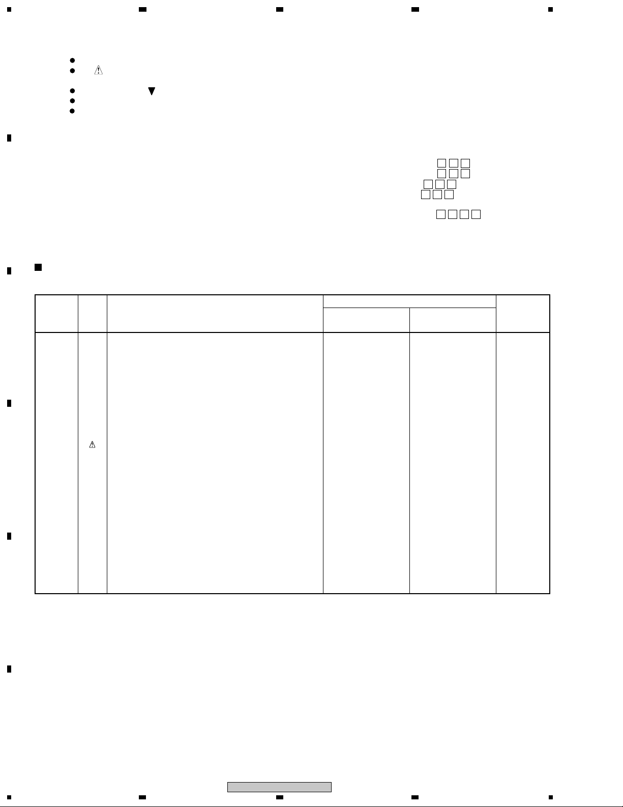
1. CONTRAST OF MISCELLANEOUS PARTS
NOTES:
A
B
CONTRAST TABLE
PDP-R03K/WK and PDP-R03U/KUC are constructed the same except for the following :
Ref. No. Mark Symbol and Description PDP-R03U PDP-R03K Remarks
C
P9-41 MAIN UNIT DUNTKA535FE04 DUNTKA535FE20
P9-42 FRONT UNIT DUNTKA617DE01 DUNTKA617DE06
P9-43 AV UNIT DUNTKA616DE01 DUNTKA616DE06
P9-44 SR CONNECT UNIT DUNTKA618DE01 DUNTKA618DE06
P9-45 LED UNIT DUNTKA619DE01 DUNTKA619DE06
Parts marked by "NSP" are generally unavailable because they are not in our Master Spare Parts List.
The mark found on some component parts indicates the importance of the safety factor of the part.
Therefore, when replacing, be sure to use parts of identical designation.
Screws adjacent to mark on product are used for disassembly.
Reference Nos. indicate the pages and Nos. in the service manual for the base model.
For the applying amount of lubricants or glue, follow the instructions in this manual.
(In the case of no amount instructions, apply as you think it appropriate.)
When ordering resistors, first convert resistance values into code form as shown in the following examples.
•
Ex.1 When there are 2 effective digits (any digit apart from 0), such as 560 ohm and 47k ohm (tolerance is shown by J=5%,
and K=10%).
560 Ω→56 × 10
47k Ω→47 × 10
1
→ 561 ........................................................ RD1/4PU 5 6 1 J
3
→ 473 ........................................................ RD1/4PU 4 7 3 J
0.5 Ω→R50 ..................................................................................... RN2H
1 Ω→1R0 ..................................................................................... RS1P
Ex.2 When there are 3 effective digits (such as in high precision metal film resistors).
5.62k Ω→ 562 × 10
1
→ 5621 ...................................................... RN1/4PC 5 6 2 1 F
/KUC /WK
PCB ASSEMBLIES
Part No.
R 5 0
1 R 0
4
K
K
P9-46 PC I/F UNIT CPCI-0056CE15 CPCI-0056CE17
P9-48 EMC UNIT RDENCA007WJZZ RDENCA006WJZZ
P7- 1 Power Cord QACCDA007WJPZ Not used
P7- 6 PDP Caution TCAUH1223CEZZ Not used
D
E
P7- 7 System Cable Caution TCAUH1227CEZZ Not used
P7- 8 Caution Card TCAUH1231CEZZ Not used
P7- 9 Packing Case SPAKC5648CEZZ SPAKCA093WJZZ
P9- 1 Bottom Cabinet Assy CCABA3103CE01 CCABA3103WJ05
P9- 1-3 Terminal Indicator HINDP5928CESA HINDPA080WJSA
P9- 1-7 Model Label TLABM4302CEZZ TLABMA066WJZZ
P9- 2 Front Panel Assy CWAKP1474CE01 CWAKPA001WJ01
P9- 4 Top Cabinet Assy CCABB3078CE01 Not used
P9- 4-1 Top Cabinet Not available GCABB3078CESA
P9- 4-2 Caution Label TCAUHA001WJZZ Not used
P9- 21 Serial No. Label TLABN0411CEZZ TLABNA040WJZZ
Notes : For PCB ASSEMBLIES, Refer to “CONTRAST OF PCB ASSEMBLIES” and “2. SCHEMATIC DIAGRAM”.
PACKING SECTION
EXTERIOR SECTION
F
2
1234
PDP-R03K
Page 3
1
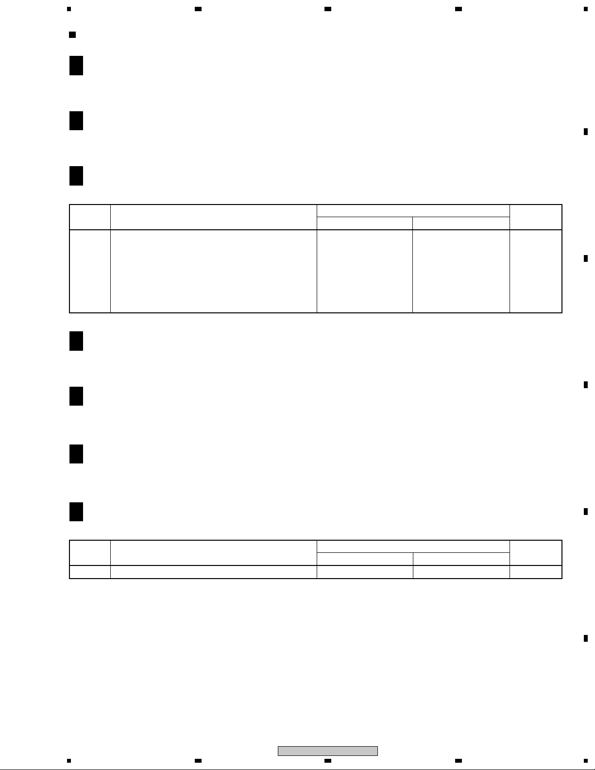
CONTRAST OF PCB ASSEMBLIES
234
MAIN UNIT
A
F
Although DUNTKA535FE20 and DUNTKA535FE04 are different in part number, they have the same service parts.
FRONT UNIT
B
F
Although DUNTKA617DE06 and DUNTKA617DE01 are different in part number, they have the same service parts.
C
AV UNIT
F
DUNTKA616DE06 and DUNTKA616DE01 are constructed the same except for the following :
Mark Symbol and Description
Q1581 2SA1298Y Not used VS2SA1298Y/-1Y
Q1582 DTC144TE Not used VSDTC144TE/-1Y
D1581–D1583 Diode Not used VHDHSU119//-1
C1581 22µF/16V Electrolytic Not used VCEAPF1CW226M
R1581 33Ω/1W Metal Oxide Not used VRS-CR3AD330J
R1582 10kΩ/ 1/16W Metal Oxide Not used VRS-CY1JF103J
R1583 560Ω/ 1/16W Metal Oxide Not used VRS-CY1JF561J
R1584 1.0kΩ/ 1/16W Metal Oxide Not used VRS-CY1JF102J
LED UNIT
D
F
DUNTKA616DE01 DUNTKA616DE06
Part No.
Remarks
A
B
C
Although DUNTKA619DE06 and DUNTKA619DE01 are different in part number, they have the same service parts.
SR CONNECT UNIT
E
F
Although DUNTKA618DE06 and DUNTKA618DE01 are different in part number, they have the same service parts.
PC I/F UNIT
F
F
Although CPCI-0056CE17 and CPCI-0056CE15 are different in part number, they have the same service parts.
EMC UNIT
H
F
RDENCA006WJZZ and RDENCA007WJZZ are constructed the same except for the following :
Mark Symbol and Description
R741, R742 5.6MΩ/ 1/2W Carbon RR-RCR50+565J Not used
RDENCA007WJZZ RDENCA006WJZZ
Part No.
Remarks
D
E
F
1
2
PDP-R03K
3
4
3
Page 4
1
23
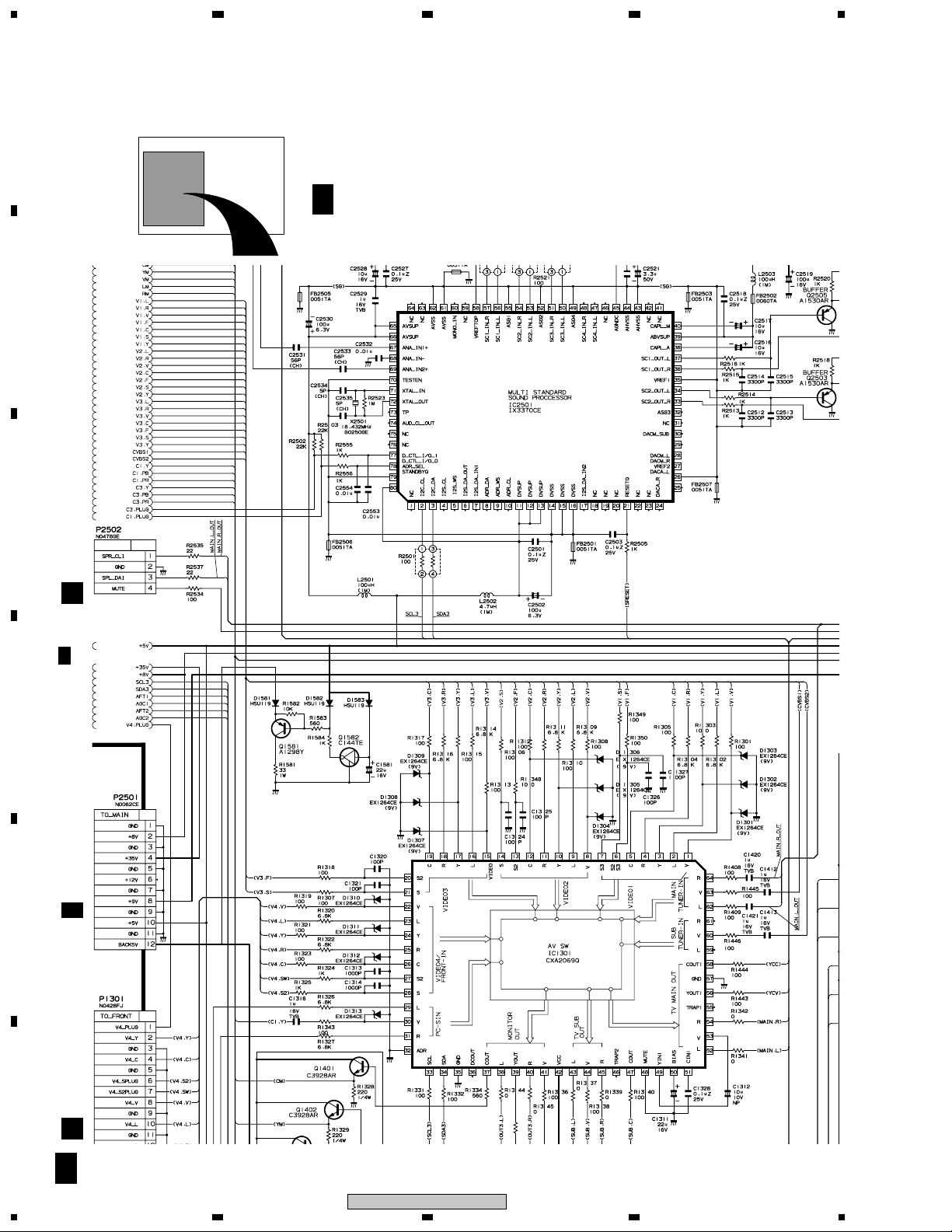
2. SCHEMATIC DIAGRAM
Note : When ordering service parts, be sure to refer to "EXPLODED VIEWS and PARTS LIST" or "PCB PARTS LIST"
A
2.1 AV UNIT
4
C 2/3
C 2/3F
B
C
P6001
AV UNIT (DUNTKA616DE06)
E
C
1/3
D
P1703
E
A 7/7
C
4
P3402
B
2/3F
PDP-R03K
1234
F
 Loading...