

Page 1
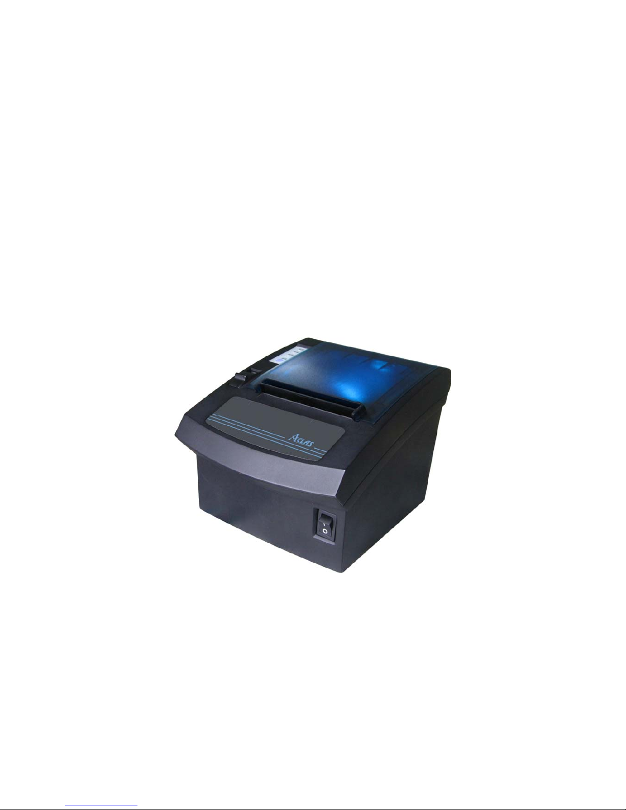
PP7X PRINTER
OPERATION MANUAL
Pinnacle Technology Corp.
Page 2

Page 3

CONTENTS
1 FEATURES ....................................................................................................................................................... 1
2 SPECIFICATIONS............................................................................................................................................ 1
3 ACCESSORIES................................................................................................................................................. 2
4 GET TO KNOW THE PRINTER...................................................................................................................... 2
5 DRAWER PORT DEFINITION........................................................................................................................ 5
6 INSTALLATION AND MAINTENANCE ....................................................................................................... 6
6.1 Paper Installation ............................................................................................................................... 6
6.2 Print Test Page ................................................................................................................................... 8
6.3 Thermal Printer Head Cleaning ......................................................................................................... 8
6.4 Communication Board Replacement................................................................................................. 9
7 MODEL: PP7XU............................................................................................................................................. 11
7.1 Printer Driver Installation ................................................................................................................ 11
7.2 How to Know the Connecting Port.................................................................................................. 16
7.3 Software Description ....................................................................................................................... 18
8 MODEL: PP7XW4/PP7XW2.......................................................................................................................... 19
8.1 Wireless 433MHz Base Station ....................................................................................................... 19
8.2 Wireless 433 USB Dongle/2.4G...................................................................................................... 21
8.2.1 USB Dongle Driver Installation............................................................................................... 21
8.2.1 How to Know the Connecting Port.......................................................................................... 21
8.3 Printer Driver Installation ................................................................................................................ 23
8.4 Software Description ....................................................................................................................... 24
9 MODEL: PP7XE ............................................................................................................................................. 26
9.1 Printer Driver Installation ................................................................................................................ 26
9.2 Software Description ....................................................................................................................... 30
10 MODEL: PP7XD..................................................................................................................................... 31
10.1 How to Know the Connecting Port.................................................................................................. 31
10.2 Printer Driver Installation ................................................................................................................ 32
11 MODEL: PP7X3.............................................................................................................................................. 33
11.1 How to Know the Connecting Port.................................................................................................. 33
11.2 Printer Driver Installation ................................................................................................................ 33
11.3 Software Description ....................................................................................................................... 34
12 MODEL: PP7XWB ................................................................................................................................. 35
12.1 BT Driver Installation...................................................................................................................... 35
12.2 How to Know the Connecting Port.................................................................................................. 45
12.3 Printer Driver Installation ................................................................................................................ 46
12.4 Software Description ....................................................................................................................... 47
13 DIP SWITCH..................................................................................................................
......................... 48
14 COMMANDS.......................................................................................................................................... 50
15 COMMAND SAMPLE (hex command) ................................................................................................. 72
Page 4

1
1 FEATURES
※ Original patented oblique paper-sensor. Detect the paper precisely, even if the paper is stuck to the end
of paper slot or paper roll is in different position (desktop or hang on the wall).
※ Special paper cutter design (the movable cutter is on the upper side). In this case, paper jam problem
can be solved by simply opening the printer cover. Currently ordinary printers cannot solve the paper
jam problem easily, only by pull back the gear to return the cutter.
※ With black mark sensor.
※ Optional automatically Paper-cutter module.
※ Unique mechanism to make paper installation easily.
※ With water-proof design. The rubber sticker in the paper outlet is able to prevent from water, oil.
※ Support with ESC/POS command collection, in addition to Aclas protocol.
※ POS printer: supermarket, restaurants, retails to print the sales receipt.
※ Can work as a fiscal printer, by adding optional displays (client&operator) and functional keys.
2 SPECIFICATIONS
Print Method thermal print
Resolution 203dpi
Speed 150mm/s (PP7MX); 250mm/s (PP7HX)
Printer Head Life 50km
Effective Width 72mm
Paper Width 80mm±0.1
Paper Feed roll feeding
Power Supply DC24V 2A Adapter (AC100~240V)
Interface
1 cash drawer interface compatibles with EPSON
1 USB port (PP7XU)
1 parallel port (PP7XD)
1 Ethernet port (PP7XE)
1 RS232 port (PP7XW4/PP7X3/PP7XW2/PP7XWB)
Work Temperature 0℃ ~ 40℃
Work Humidity 5% ~ 85%
Weight approx. 0.82kg
Size 196.5*145*135mm
Page 5
2
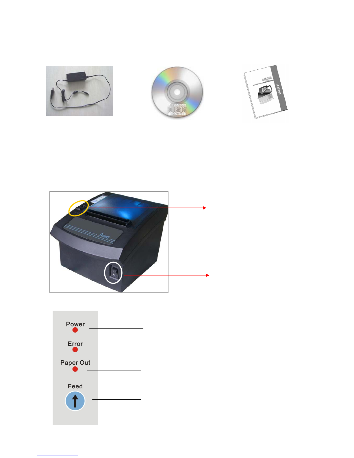
3 ACCESSORIES
4 GET TO KNOW THE PRINTER
Power indicator light
To prompt error
To prompt the paper is run out
Press this key to advance paper
PC Disk
User manual
Adapter
Power switch
The switch to open the upper cover
Page 6
3
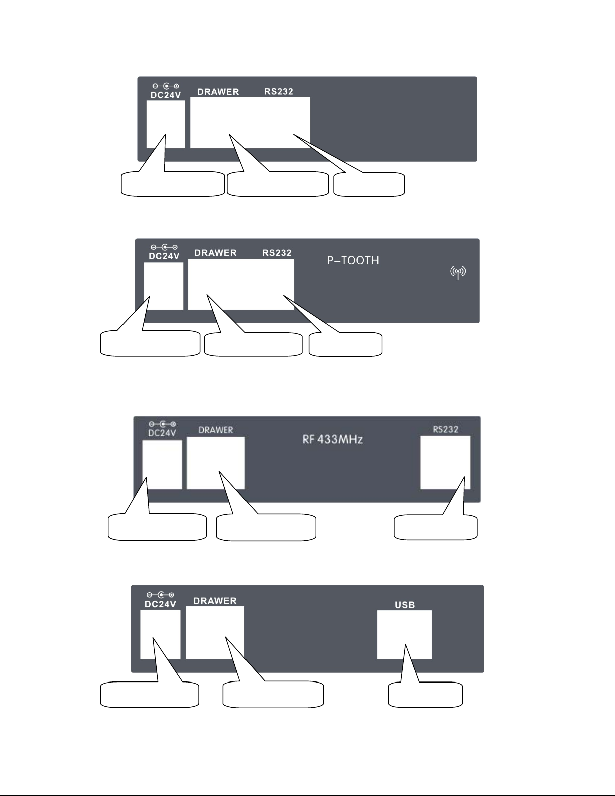
INTERFACE:
Connect to charger
Connect to drawer
USB port
[Model: PPXU]
[Model: PP7XW4]
Connect to charger
Connect to drawer
RS232 port
Connect to charger
Connect to drawer
RS232 Port
[Model: PP7X3]
Connect to charger
Connect to drawer
RS232 Port
[Model: PP7XW2]
Page 7
4
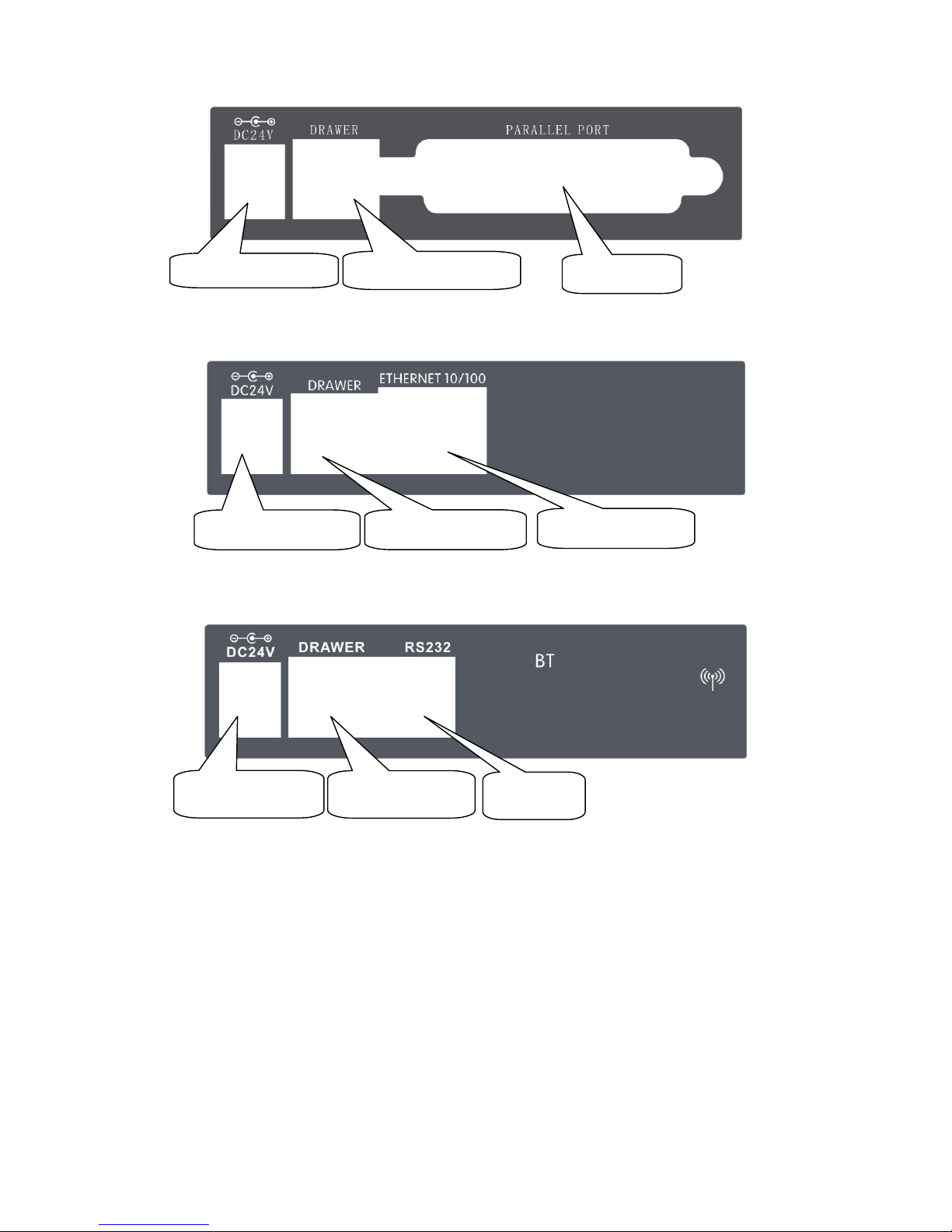
Connect to charger
Connect to drawer
Parallel port
[Model: PP7XD]
Connect to charger
Connect to drawer
Ethernet port
[Model: PP7XE]
Connect to charger
Connect to drawer
RS232 Port
[Model: PP7XWB]
Page 8
5
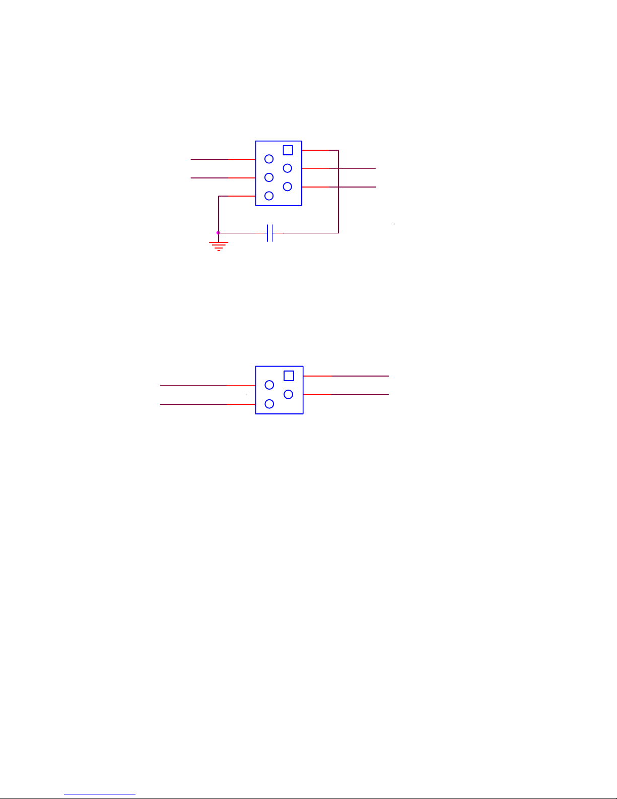
5 DRAWER PORT DEFINITION
The drawer port definition is similar to EPSON. The definition of 6PIN port is as follows:
The definition of 4PIN port (Pinnacle self-defined) is as follows:
1
2
3
4
5
6
DRAWER
PHONE6P6C
12
C12
102/2KV/ DIP
GND
DRAWER_SW#
P+24V
DRAWER2#
DRAWER1#
P+24V
DRAWER2#
DRAWER_SW#
Aclas Drawer
1
2
3
4
DRAWER
PHONE4C
DRAWER1
Page 9
6
6 INSTALLATION AND MAINTENANCE
6.1 Paper Installation
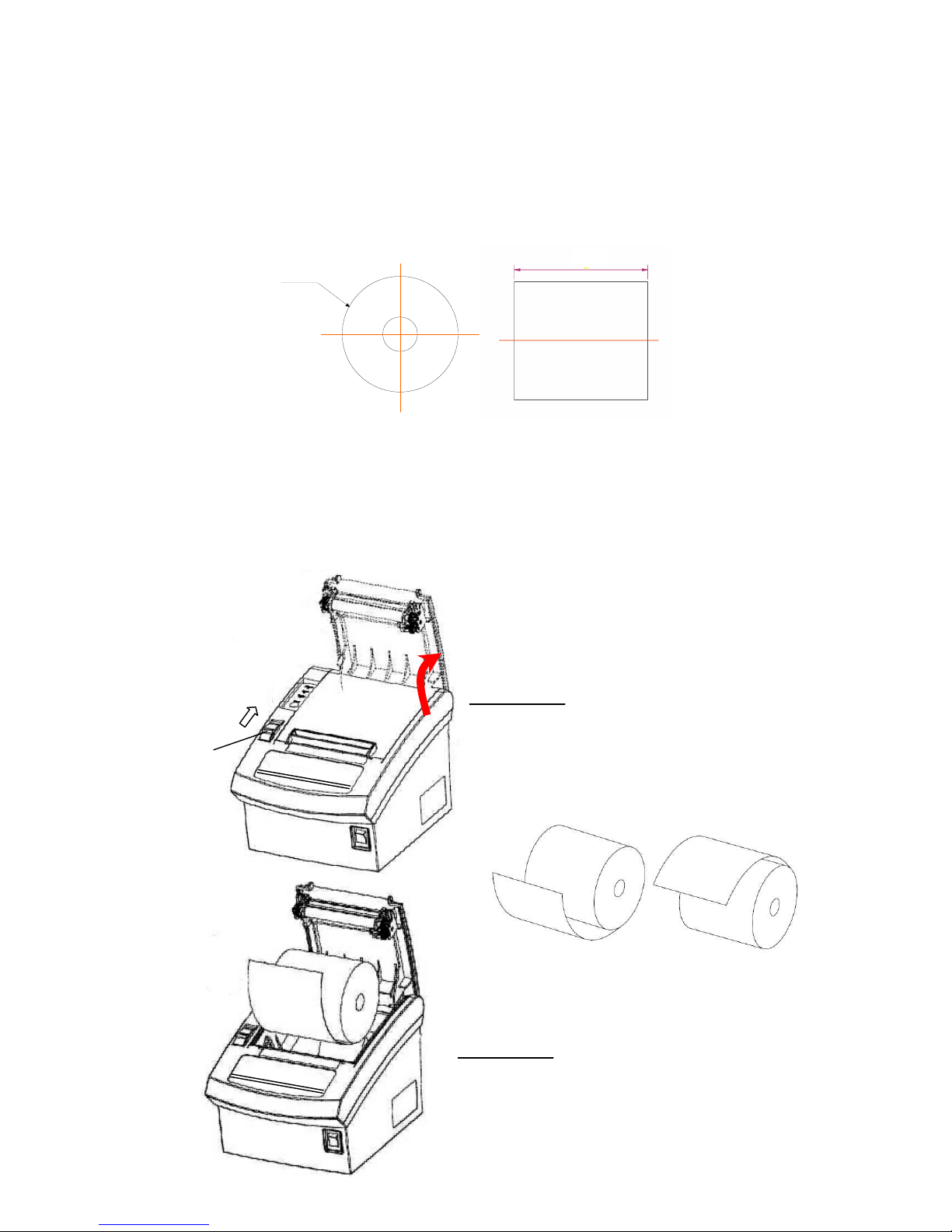
¾ Paper roll diemnsion:
Unit: mm
Note: Bad quality thermal paper may quickly damage the thermal printer head, please use high quality
thermal paper. (Bad quality thermal paper: roughness paper surface may quickly wear the pinter head; bad
sensetive result in selecting ‘dark’ density level, which may reduce the life time of the printer head.)
¾ Installation:
When there is no paper in the printer, the light ‘Paper Out’ will be on, and you need to install paper
immediately.
The switch
1. Push the switch as the arrow shows in
the picture to open the cover.
2. Place the paper roll into the paper
house.
Right
Wrong
Φ80
Φ80
Page 10
7
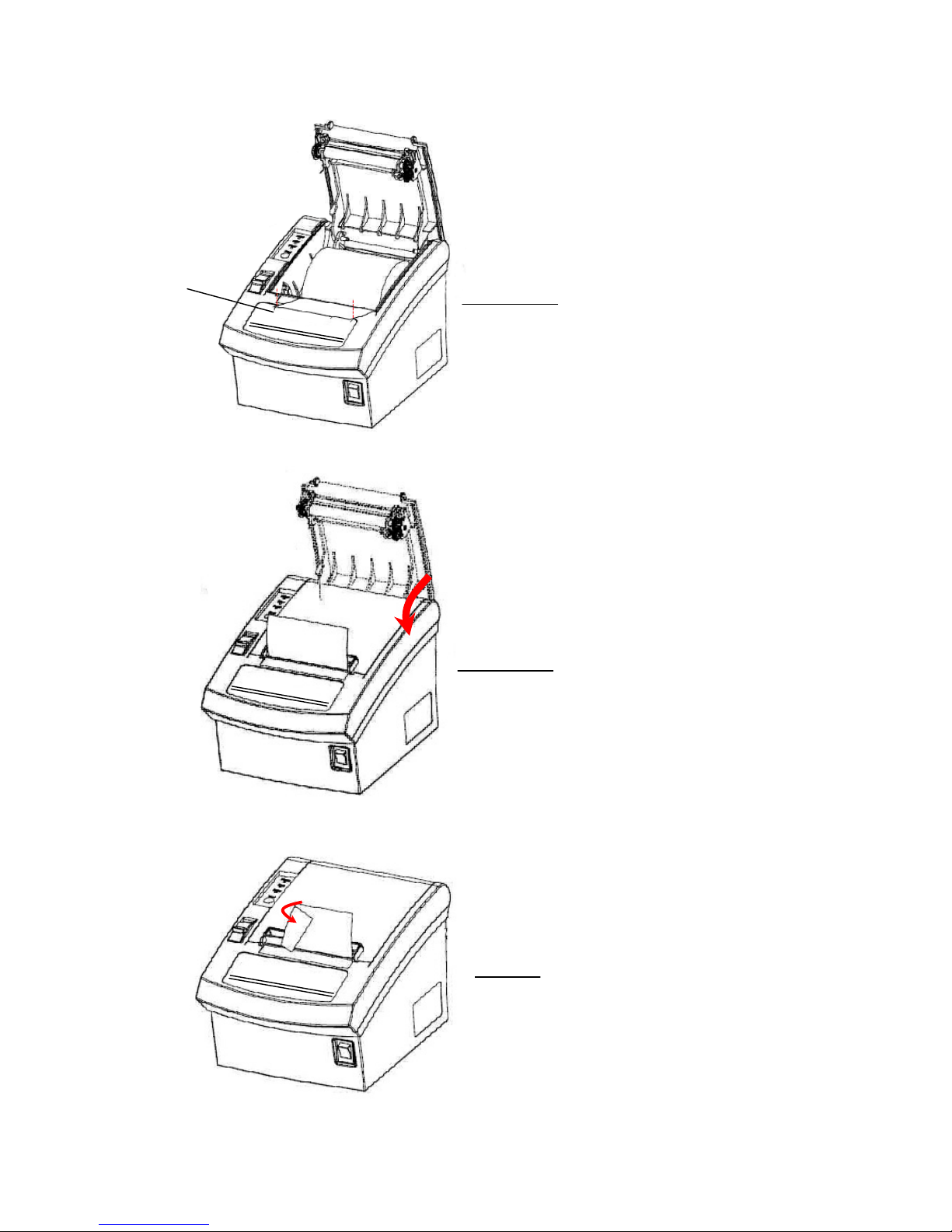
4. Pull out the leading age of paper and
close the printer cover.
5. Tear off the spear paper and finish
paper replacing.
3. Let the paper parallel with the
alignment line.
The alignment line
Page 11
8
6.2 Print Test Page
Press key ‘Feed’ and hold it, and then power on the machine at the same time, it will print a piece of Test
Page. The information of this Test Page includes the printer’s model, version, IP address (Ethernet port), ID and
the default setting of the dip switch when leave factory.
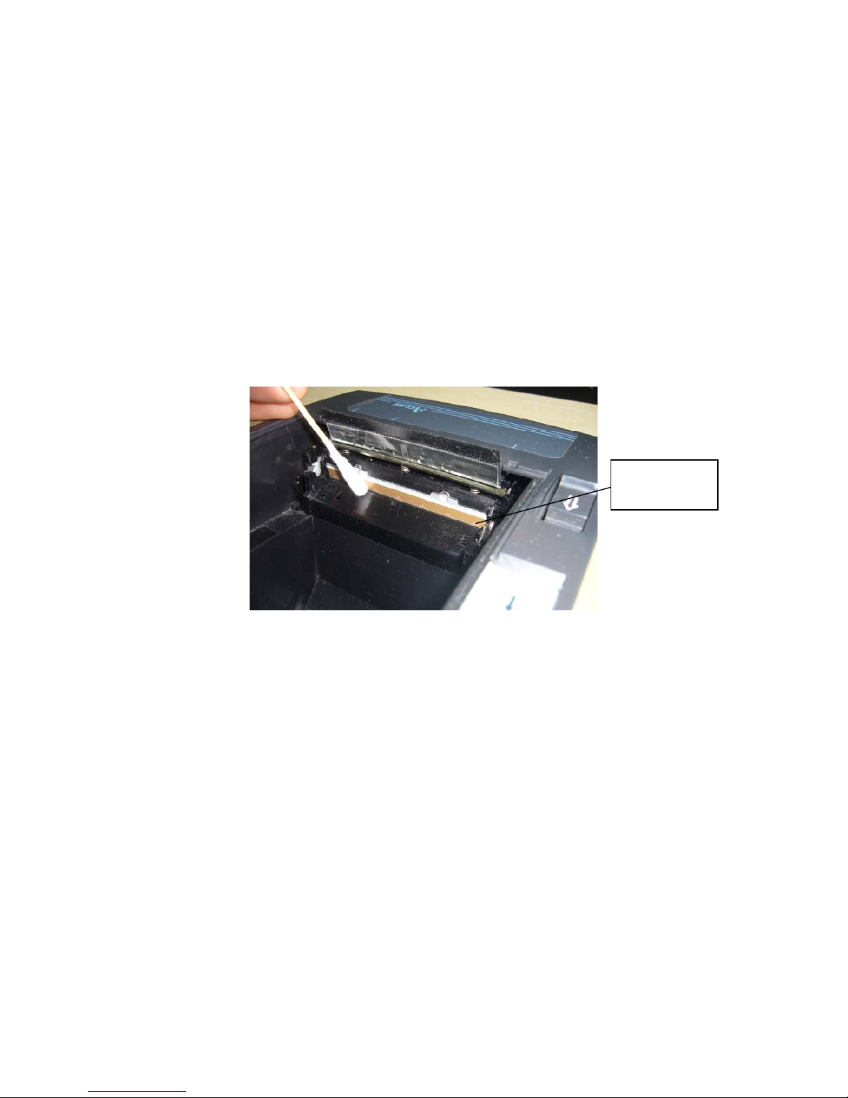
6.3 Thermal Printer Head Cleaning
The thermal printer head is probably dirty, if part of letters is not printed distinctly. Please clean the thermal
printer head by alcohol dabbed swab, otherwise heat will be hard to dissipate, which may damage the printer head.
Note: High-quality thermal paper is able to reduce possibilities of polluting the printer head, and almost
no need to clean it.
Attention: Do not touch the thermal printer head.
Thermal Printer
Head
Page 12
9
6.4 Communication Board Replacement
Note: Make sure that PP7X is powered off when you are changing the communication board. Power
off PP7X for more than 10s, then the communication board can be replaced.
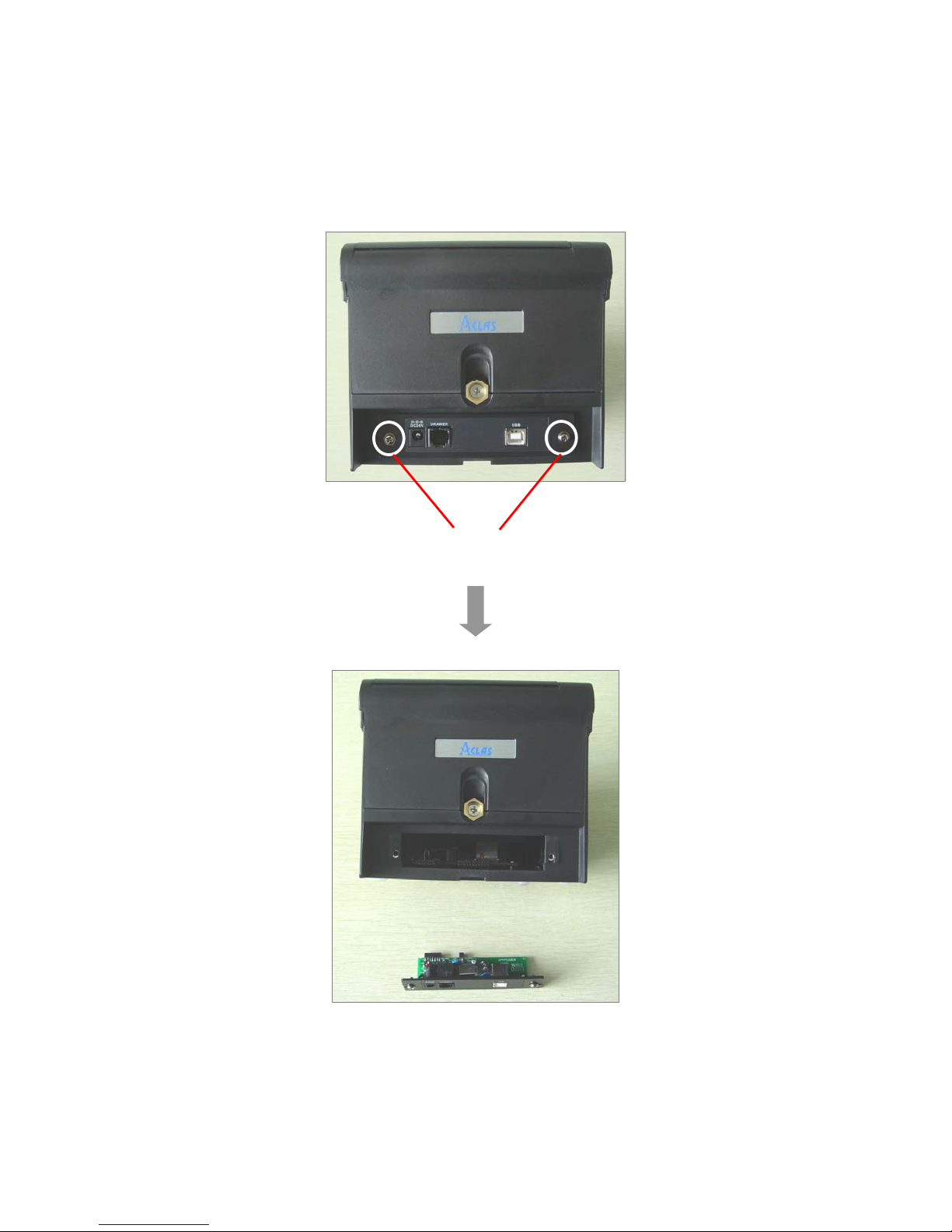
Use the cross screwdriver unscrew these two screws.
Take off the communication board and replace it.
Note: we suggest that you should
tighten the two screws side by
side to avoid damaging the main
board.
Page 13
10
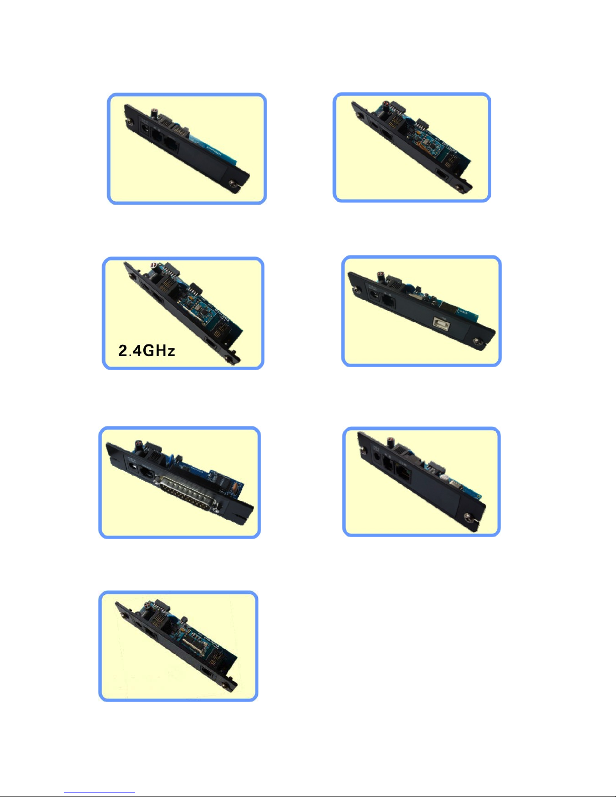
You can change the following communication boards according to your needs. And after replacement,
please refer to the corresponding chapter according to the model.
USB port module
[
Model: PP7XU
]
Parallel port module
[Model: PP7XD]
433MHz wireless port module
[Model: PP7XW4]
P-tooth wireless
communication port module
[Model: PP7XW2]
BT wireless
communication port module
[
Model: PP7XWB
]
RS232 port module
[Model: PP7X3]
Ethernet port module
[Model: PP7XE]
Page 14
11
7 MODEL: PP7XU
7.1 Printer Driver Installation
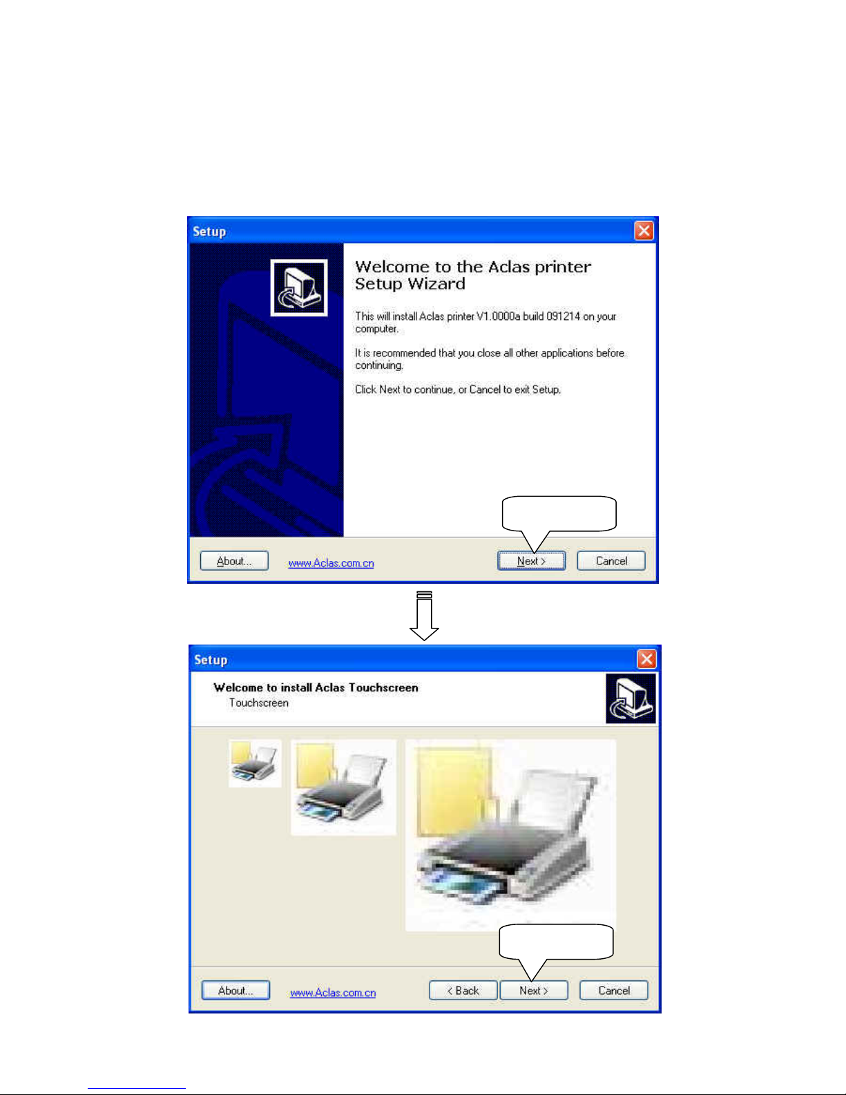
Connect the PP7X to PC. Click ‘Aclas printer.exe’ on the CD-disk, which is packed along with your
computer. Install the printer driver as follows:
Click ‘Next’
Click ‘Next’
Click ‘Next’
Page 15
12
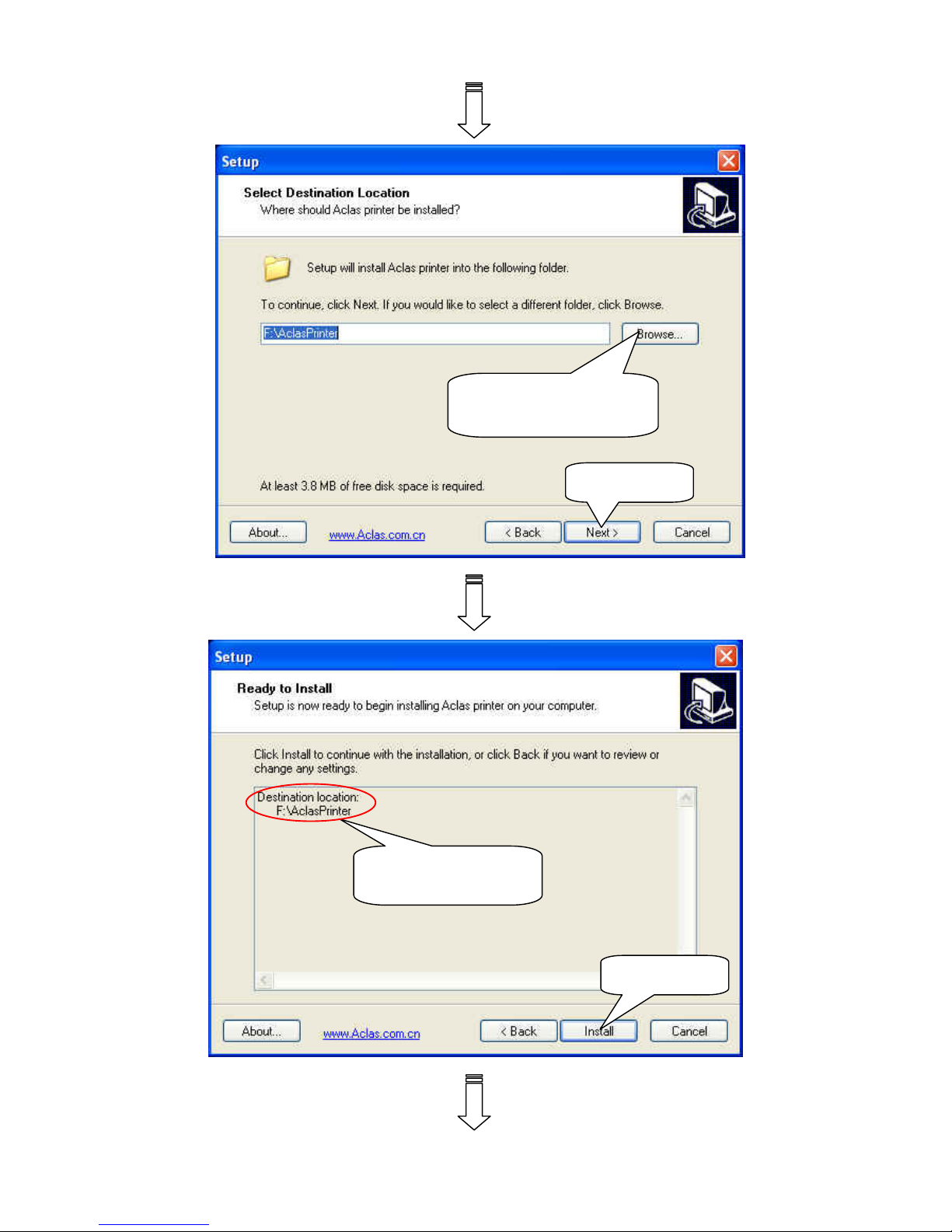
Click ‘Browse’ to select
the destination location.
Click ‘Next’
Here shows the
destination location.
Click ‘Install’
Page 16
13
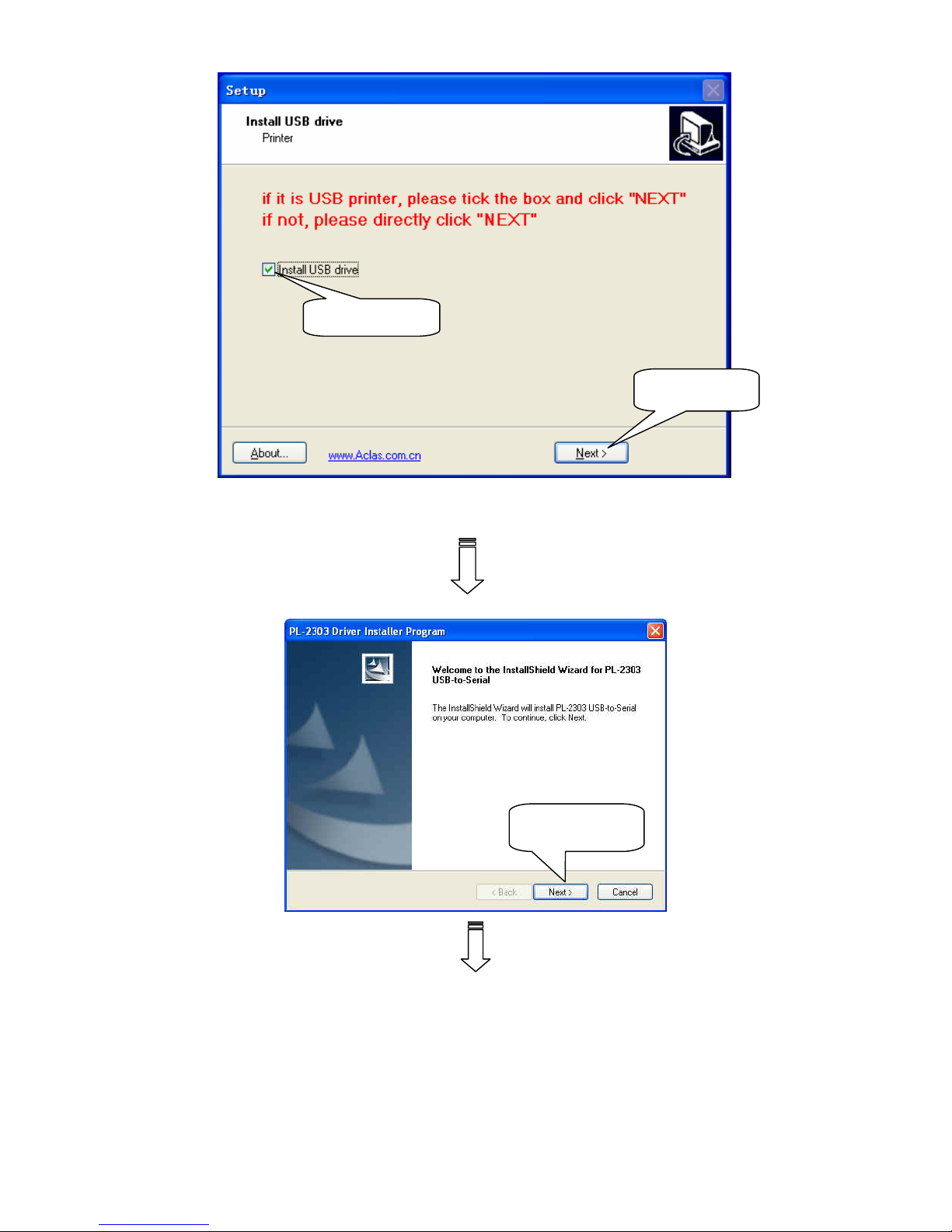
Note: If it is USB printer, please tick the box and click“NEXT”.If not, please directly click “NEXT”.
Click ‘Next’
选择如第 3.2 章,计算机
自动识别的端口
Choose this item
Click ‘Next’
Page 17
14
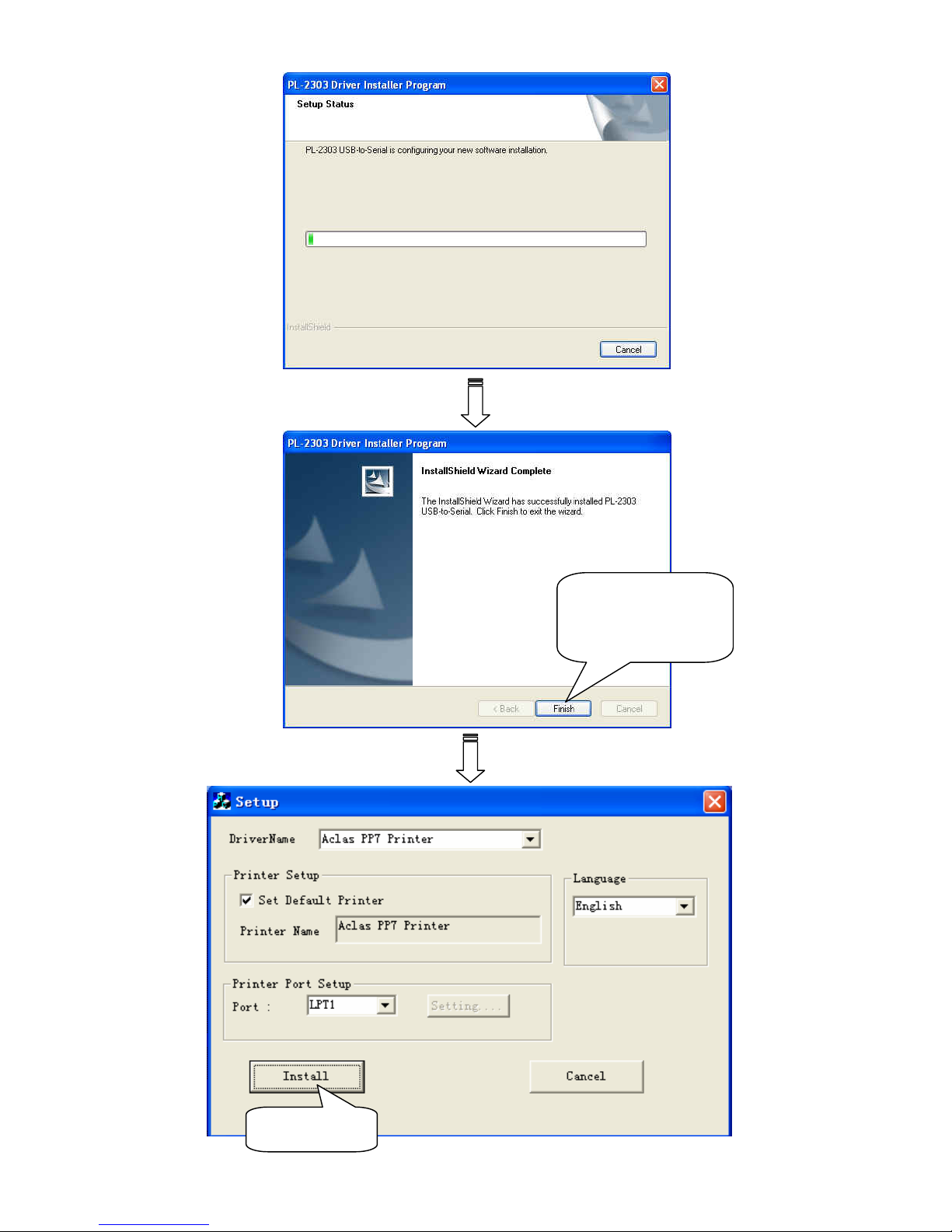
Click ‘Finish’ to
finish USB driver
installation.
Click‘Install’
Page 18
15
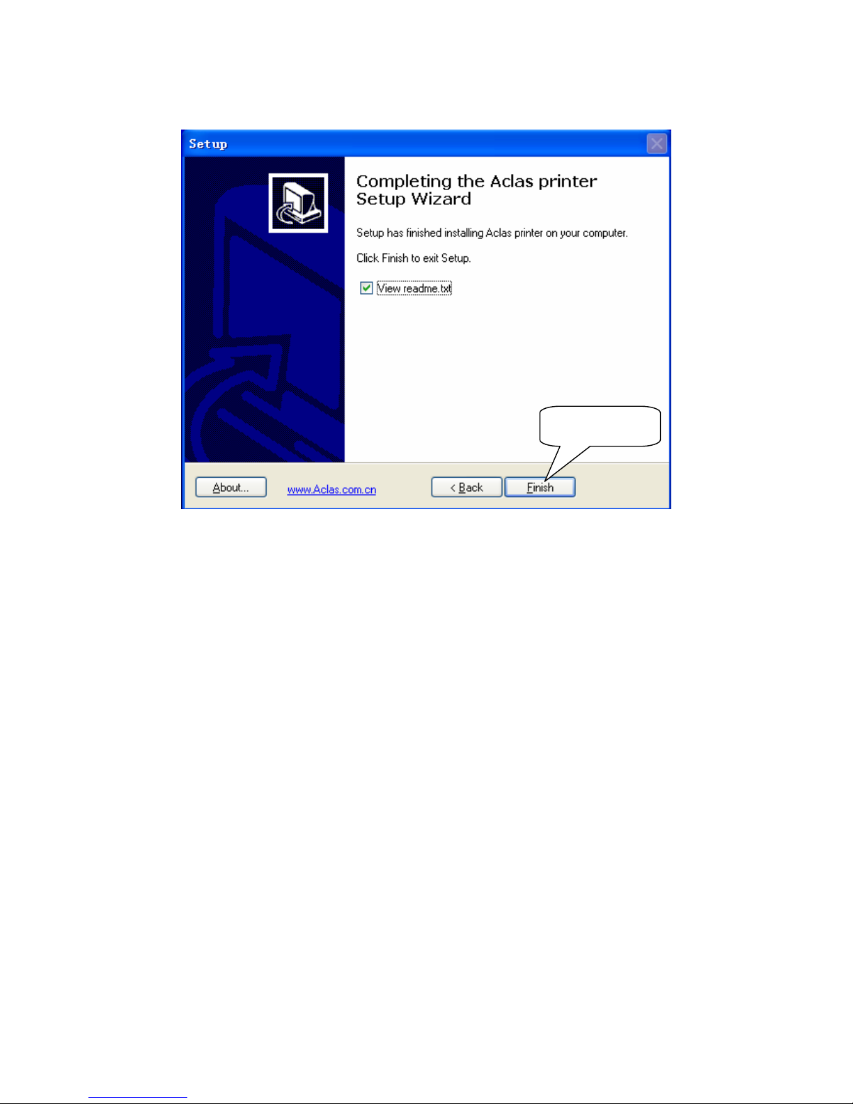
Finally, click ‘Finish’ to finish printer driver installation.
Click ‘Finish’
Page 19
16
7.2 How to Know the Connecting Port
After you install USB driver, restart computer, and connect the PP7X to the computer. Then, you can follow
steps below to know which port is connected.
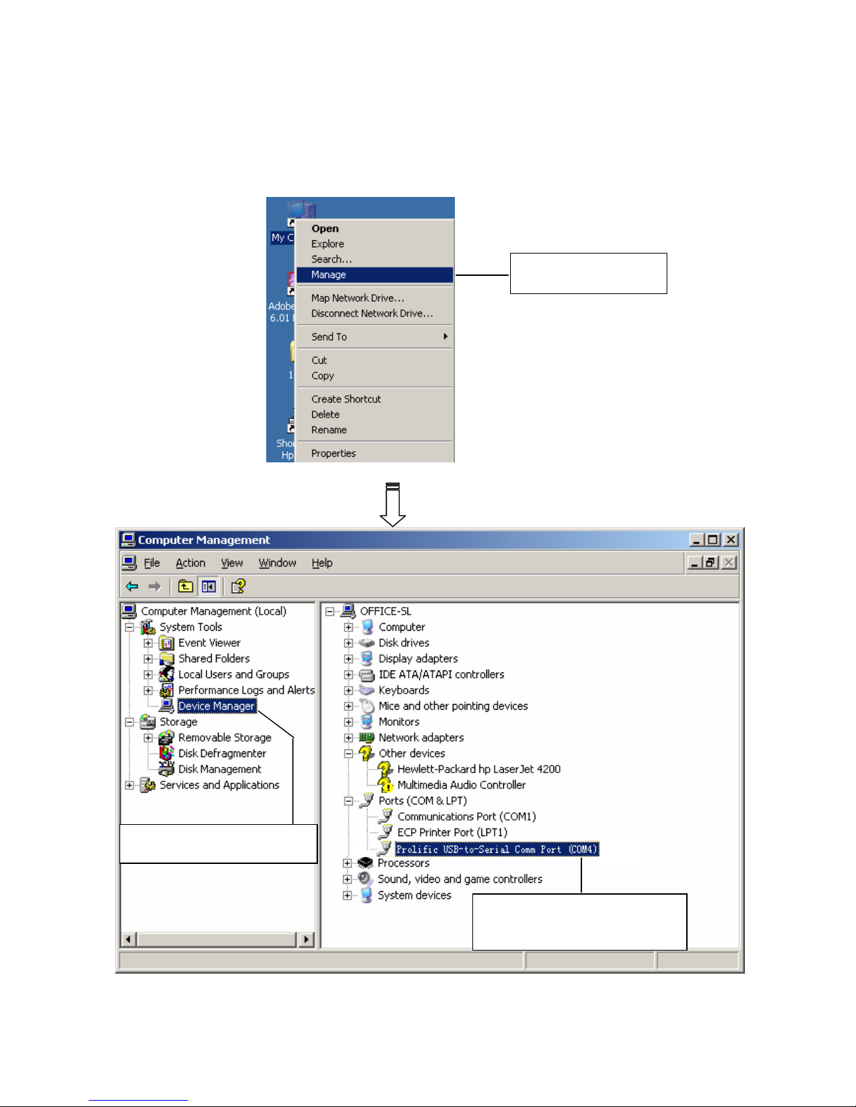
Right click ‘My Computer’ icon on the desktop, and choose ‘Manage’:
Choose ‘Manage’
Choose ‘Device Manager’
Here you can see the
connecting port.
Page 20
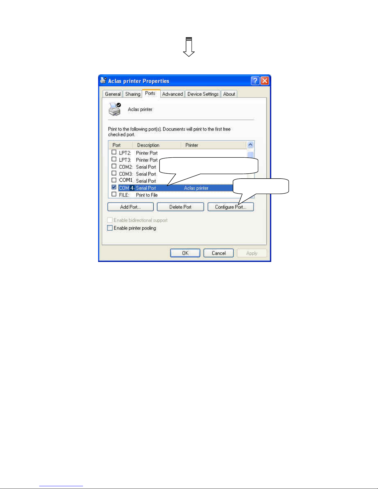
17
① Select the connecting port
② Click it.
Page 21
18
7.3 Software Description
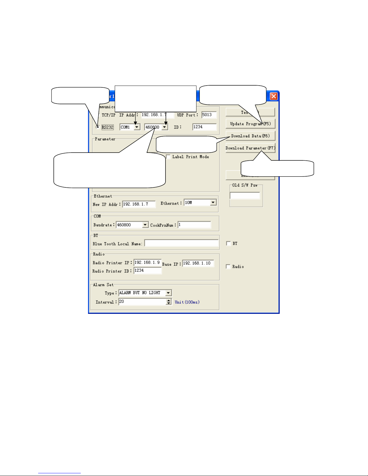
In the disk, you can find the software ‘PP7_en.exe’in the file ‘PC-SW’, double click to open it.
Here, you can use the software to update program and download data.
Connect PP7X to PC.
Note: ① Please set the baud rate as 460800 before updating program, when the downloading is paused,
click ‘Cancel’, and change the baud rate as 115200, and then you can update program again.
② The baud rate of PP7XU is fixed at ‘460800’.
③ Print density can be adjusted via Dip Switch, please refer to Chapter 13.
You can change baud rate (9600\19200\38400\115200) and print density by dip switch.
Update program
Download font
Download parameter
Choose RS232
Choose the correct port
and baud rate
During updating program, change
the baud rate here as 115200.
Please refer to Note ①.
Page 22
19
8 MODEL: PP7XW4/PP7XW2
The communication distance: PP7XW4 is up to 100m without obstacle
PP7XW2 is up to 10m without obstacle
PP7X printers of this model are able to communicate with PC by two ways, via 433MHz Base Station or
2.4G Dongle. If you use 433MHz Base Station, please refer to Chapter 8.1; if use 2.4G Dongle, please refer to
Chapter 8.2.
8.1 Wireless 433MHz Base Station
¾ Wireless Printer Setting:
If Base Station needs to communicate with printer, the following operation should be carried out.
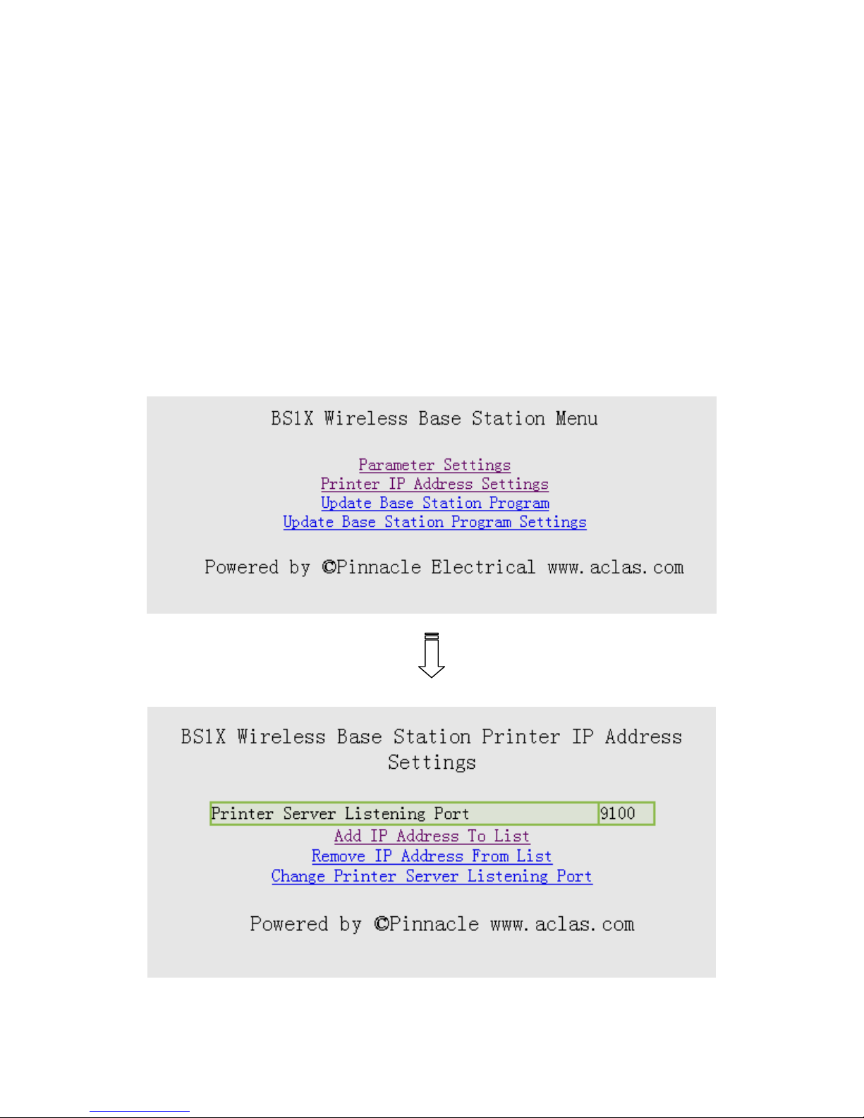
1. Enter ‘station menu’ interface, choose ‘Printer IP Address Settings’ item:
2. Add, Remove, or change printer sever listening port in the interface below:
Page 23
20
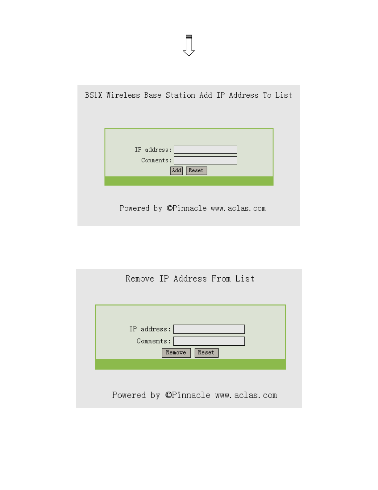
3. If choose ‘Add IP Address To List’ to add printer, please input the new added printer’s ‘IP address’
and ‘comments’, and click ‘add’; if you need to resetting, click ‘Reset’.
4. If you choose ‘Remove IP Address From List’, please input the new added printer’s IP address or
comments, and click ‘Remove’; if you need to resetting, please click ‘Reset’.
Page 24
21
8.2 Wireless 433 USB Dongle/2.4G
8.2.1 USB Dongle Driver Installation
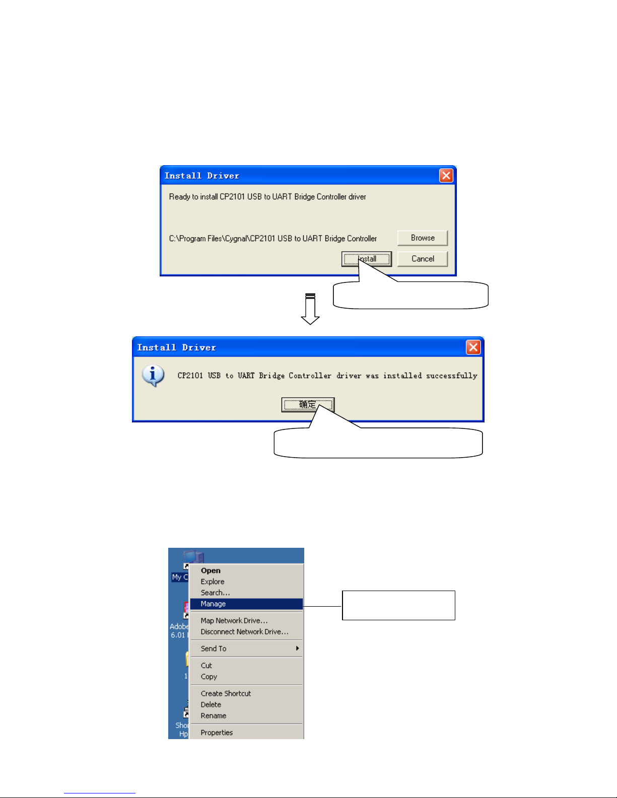
Before you install printer driver, you need to install the USB dongle driver first.
Insert the USB dongle into PC.
Double-click file Setup.exe, pop-up this window:
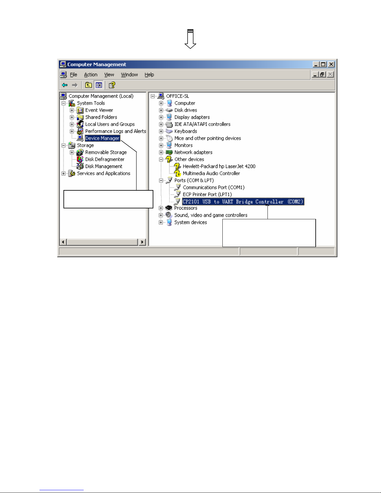
8.2.1 How to Know the Connecting Port
After you install USB dongle driver, restart computer, and insert the 433 dongle into the USB port of
computer. Then, you can follow below steps to know which port is connected.
Right click ‘My Computer’ icon on the desktop, and choose ‘Manage’:
Click this button to install.
Here shows you the installation result.
Choose ‘Manage’
Page 25
22
Choose ‘Device Manager’
Here you can see the
connecting port.
Page 26
23
8.3 Printer Driver Installation
Note: The working baudrate of wireless 433 printer is ‘9600’, its printing speed is relatively lower, it had
better not use driver printing, we suggest that you should adopt command print.
Connect the PP7X to PC. Click ‘Aclas printer.exe’ on the CD-disk, which is packed along with your
computer. And then install the printer driver, please refer to chapter 7.1 for details, and choose the printer port as
the connecting port shows in Chapter 8.2 when you install the driver.
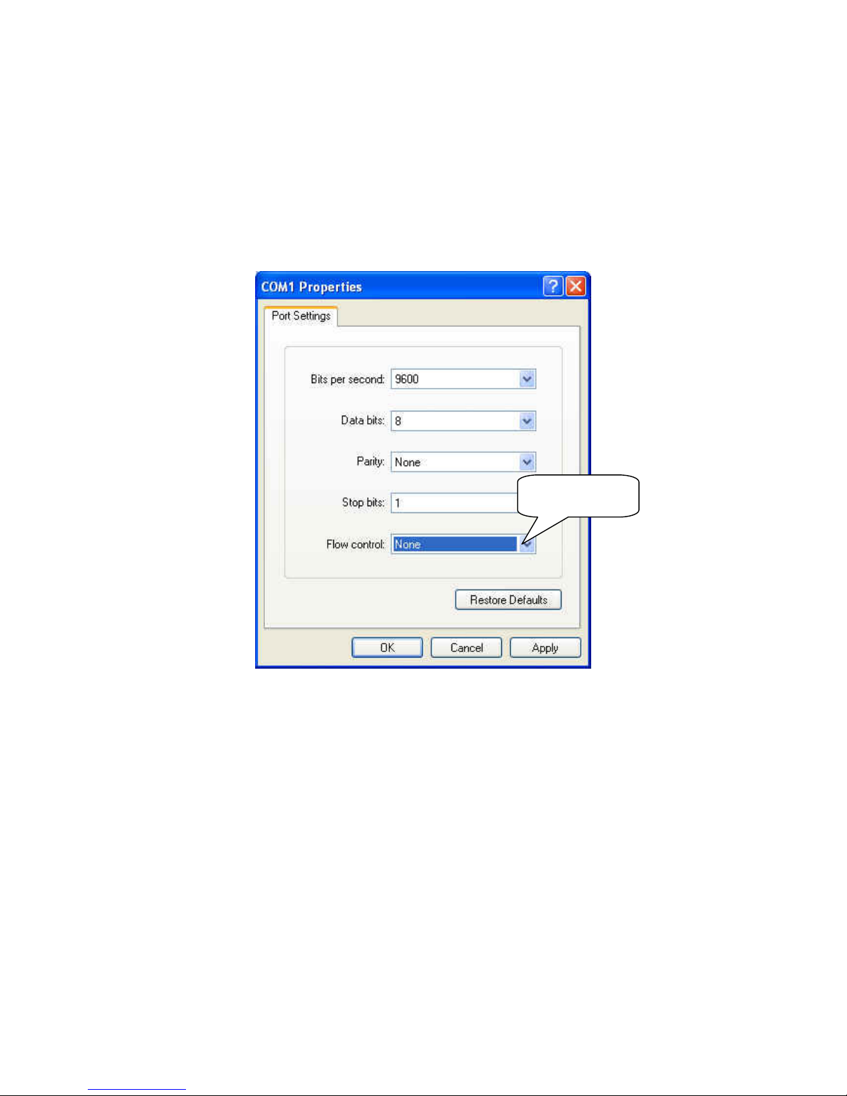
Please note that ‘Flow control’ must choose ‘Hard’ in port setting; please refer to the picture below.
Choose ‘Hard’
Page 27
24
8.4 Software Description
1. Dongle Parameter Setting
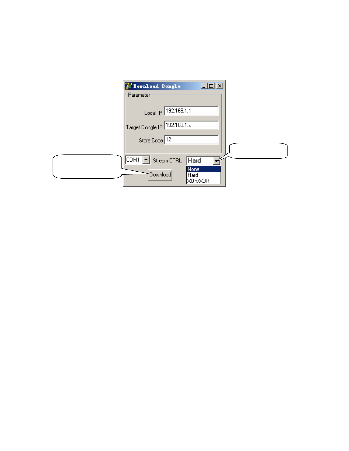
In the disk, you can find the file ‘DownloadDongle.exe’, double click to open it.
Local IP: the IP of 433 dongle.
Target Dongle IP: the wireless IP address of PP7HW4.
Str eam CTR L: stream control, if the transmitting data is over 255byte, please choose ‘Hard’. If the software is
used to transmit data, please set the stream control as ‘Hard’.
Note: After click the button ‘Download’, if the system display “Download OK”, it prompts the parameter
setting is successful, and then please pull out the dongle and insert it again; if the system display “Fail”,
please check whether you choose the correct COM port, or whether the COM port is occupied by other
equipment.
Click this button to
download setting.
Choose‘Hard’
Page 28
25
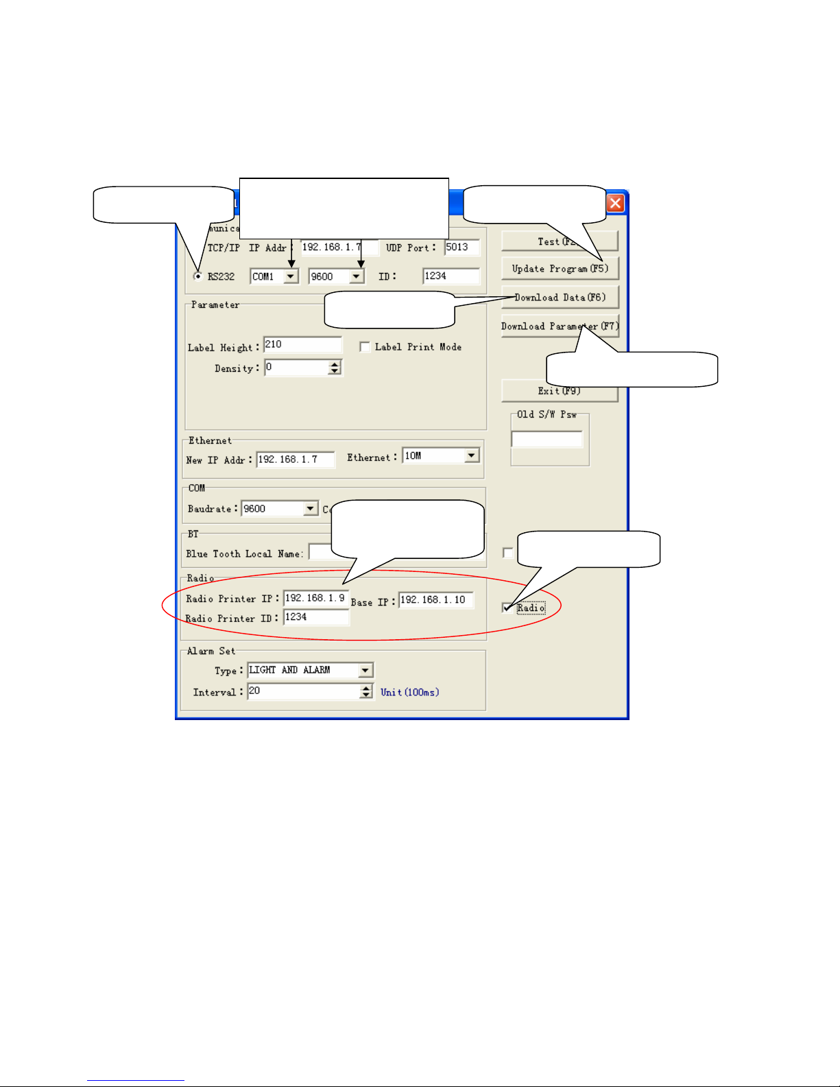
2. PP7W4/PP7W2 Parameter Setting
In the disk, you can find the software ‘PP7_en.exe’ in the file ‘PC-SW’, double click to open it.
Here, you can use the software to update program and download data.
Connect PP7X to PC.
Baud Rate: set printer baud rate, it must be 9600.
Radio Printer IP: the wireless IP address of PP7XW4/PP7XW2.
Base IP: here input the IP of 433 dongle.
Radio Printer ID: it must be the same as Store Code, or PP7XW4 cannot communicate with 433 dongle
Note:
1. Local IP should be the same with Base IP.
2. Target Dongle IP should be the same with Radio Printer IP.
3. Store Code should be the same with Radio Printer ID.
4. Printer Baud Rate must be 9600.
You must obey above notes (2 ~ 5) strictly, or the wireless communication cannot be successful.
5. If you want to communicate via communication wire directly, then you can change baud rate. The
baud rate (9600,19200,38400,115200) and the print density can be adjusted via Dip Switch, please
refer to Chapter 13 for detail.
Update program
Download font
Download parameter
Choose RS232
Choose the correct port and
baud rate
Set the printer
parameter here.
Tick up ‘Radio’.
Page 29
26
9 MODEL: PP7XE
9.1 Printer Driver Installation
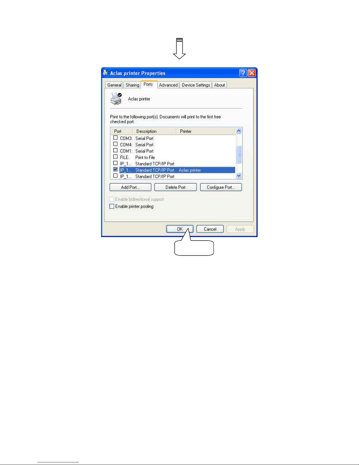
Note: If you want to use driver printing to realize many PC to communicate with many PP7X printer,
please contact our company.
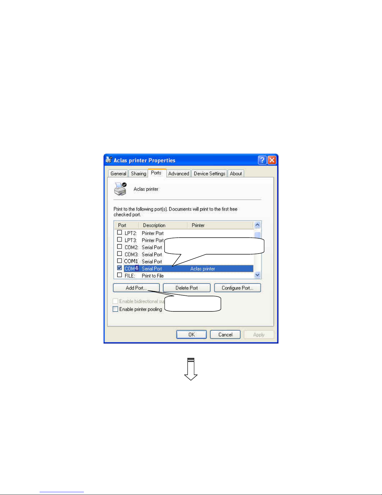
Connect the PP7X to PC. Click ‘Aclas printer.exe’ on the CD-disk, which is packed along with your
computer. And then do as Chapter 7.1, but no need to choose port or do other settings. Just install the program,
and find the file ‘Aclasprinter.inf’ in the path you installed.
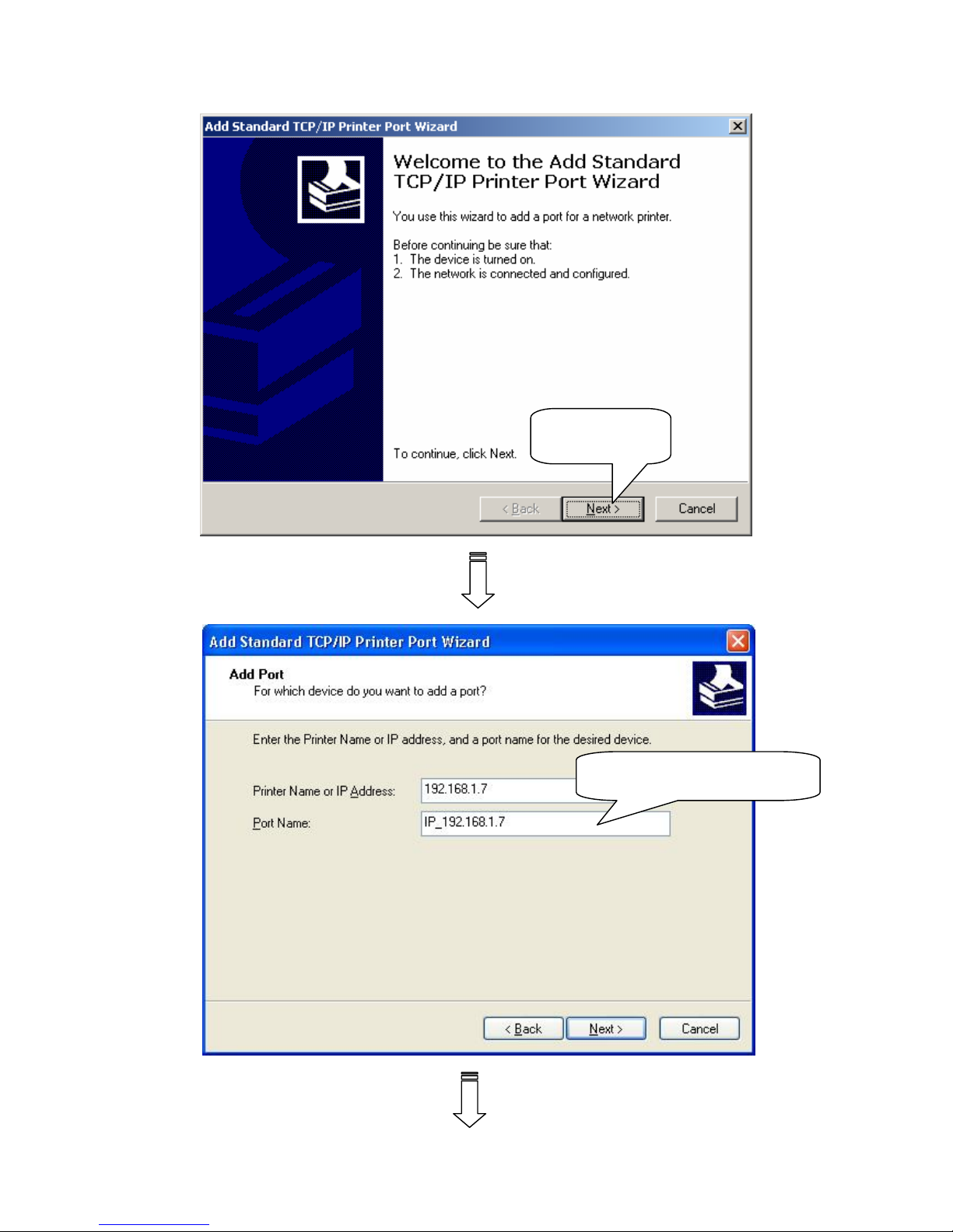
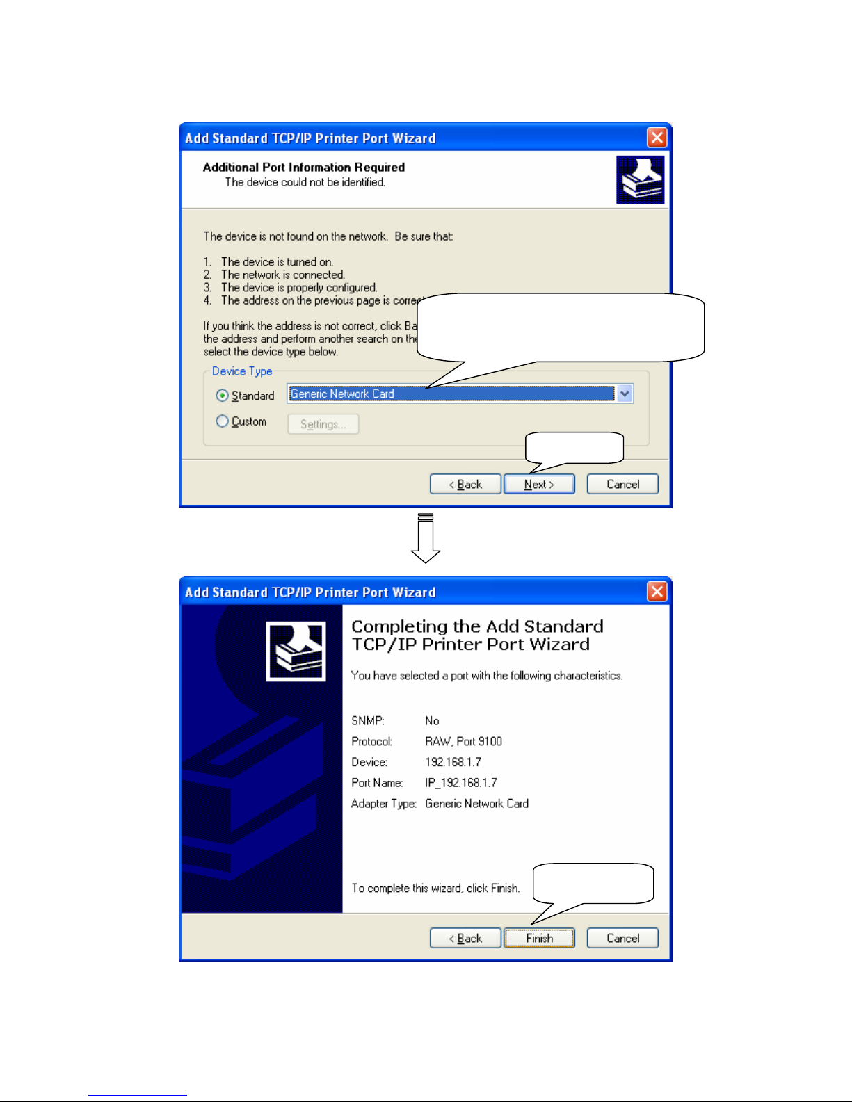
And then install the driver, please do as follows:
① Select the connecting port
② Click it.
Page 30
27
Input the printer IP address.
Click ‘Next’
Page 31
28
Choose device type, we suggest that
you choose the standard type.
Click‘Next’
Click‘Finish’
Page 32
29
Click it
Page 33
30
9.2 Software Description
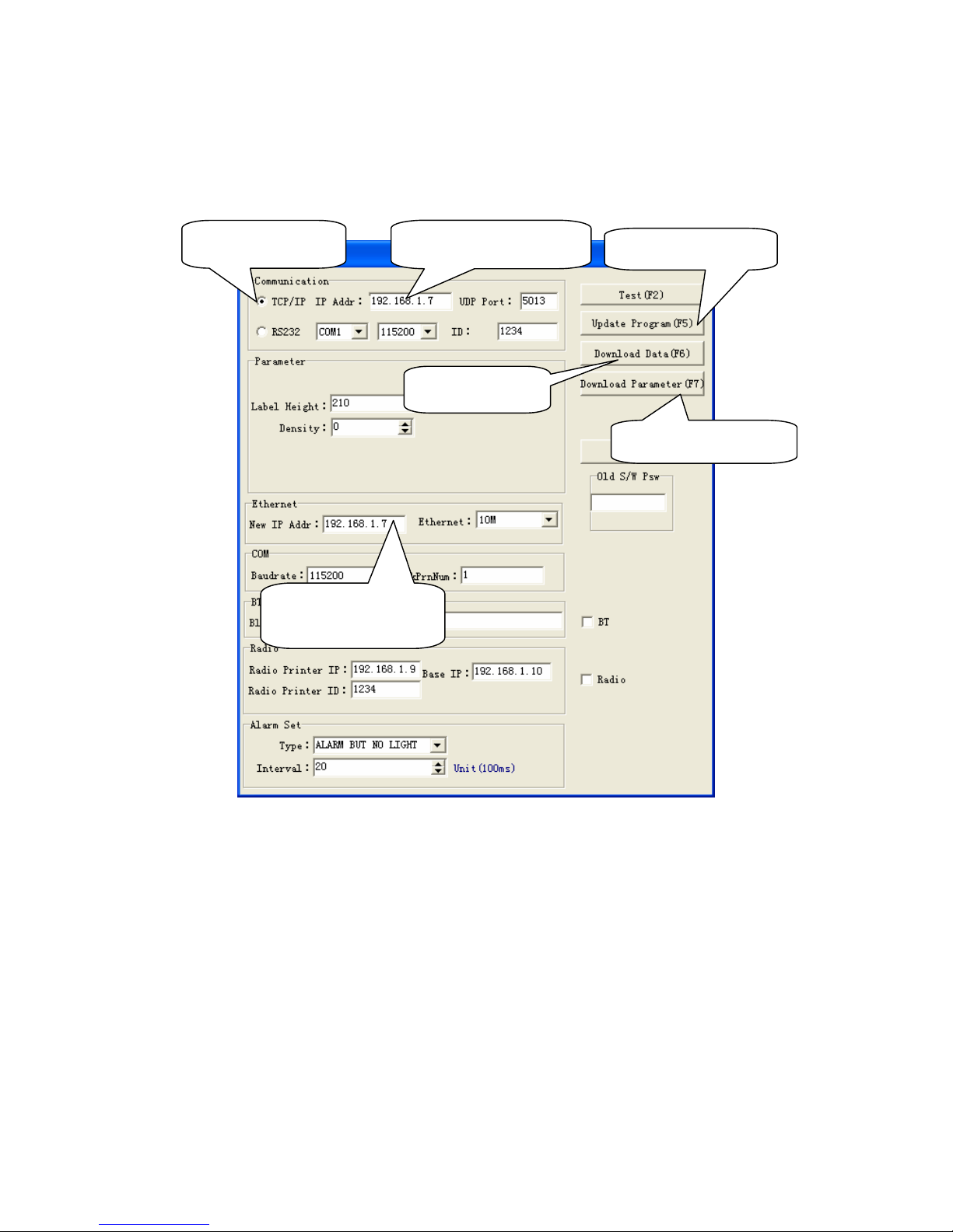
In the disk, you can find the software ‘PP7_en.exe’ in the file folder ‘PC-SW’, double click to open it.
Here, you can use the software to update program and download data.
Note: ① you can update the program at any printer’s IP.
② ‘Download Data’, means download font. Please set the parameter in the left column if choose this item.
Press ‘F6’ on the keyboard, and then choose the file in the FONT file folder.
③ ‘Download Parameter’, means download parameter. After set the parameter, press ‘F7’ on the
keyboard, and then choose the file in the Parameter file folder.
④ Print density can be changed via Dip Switch, please refer to Chapter 13 for detail.
Update program
Download font
Download parameter
Choose TCP/IP
Input the IP address
Set the new IP
address you want.
Page 34
31
10 MODEL: PP7XD
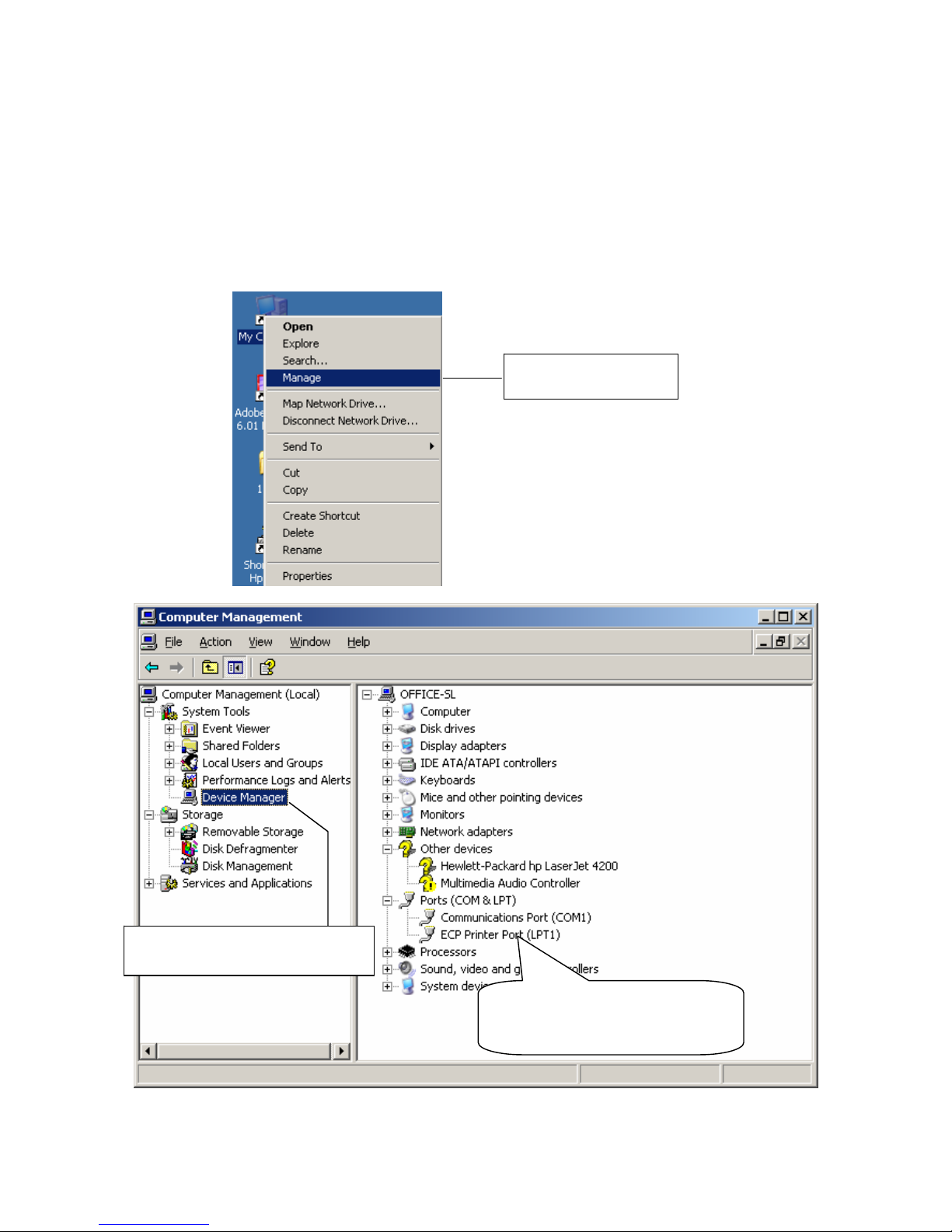
10.1 How to Know the Connecting Port
After you connect the PP7X to the computer, then, you can follow the steps below to know which port is
connected.
Right click ‘My Computer’ icon on the desktop, and choose ‘Manage’:
Choose ‘Manage’
Choose ‘Device Manager’
Here you can see the
connecting port.
Page 35

32
10.2 Printer Driver Installation
Connect the PP7X to PC. Click ‘Aclas printer.exe’ on the CD-disk, which is packed along with your
computer.
And then install the printer driver, please refer to chapter 7.1 for details, and choose the printer port as the
connecting port shows in Chapter 10.1 when you are install the driver.
If you want to update the program of PP7XD, please contact with our company (our after service hot
line is 86-592-5710087).
Page 36
33
11 MODEL: PP7X3
11.1 How to Know the Connecting Port
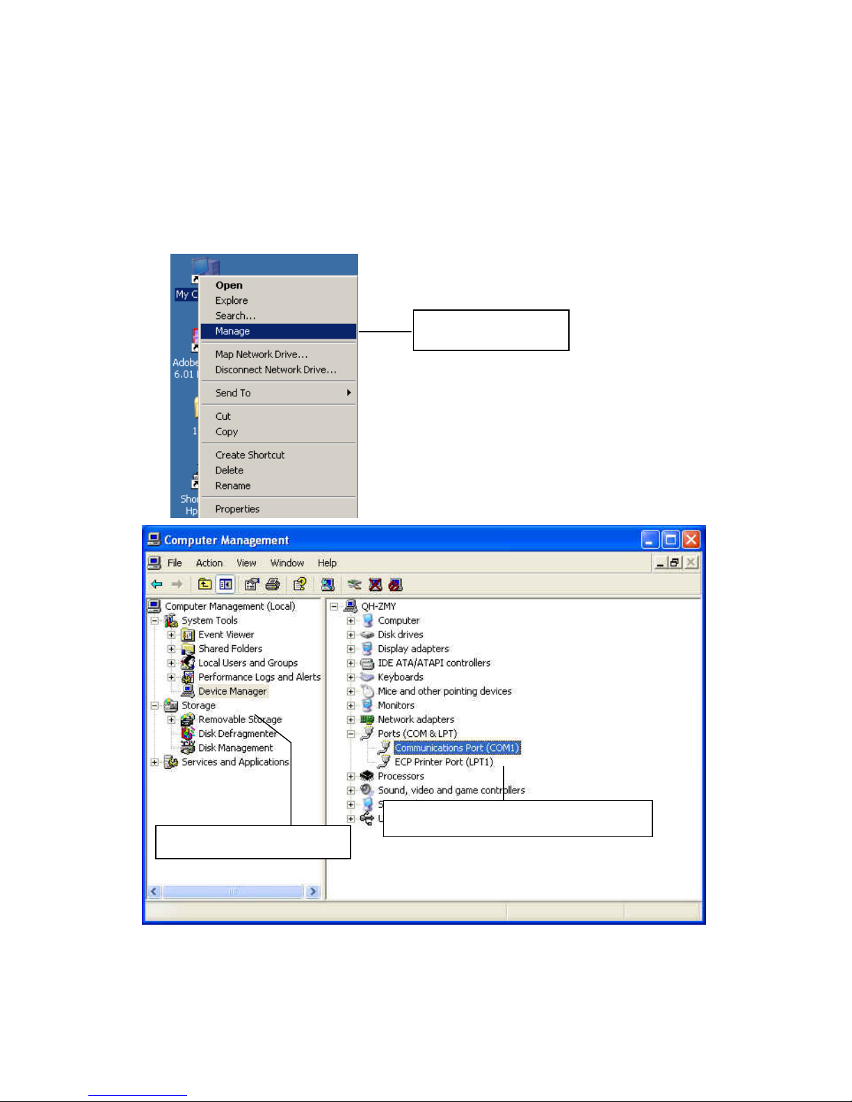
Connect the PP7X to the computer. Then, you can follow the steps below to know which port is
connected.
Right click ‘My Computer’ icon on the desktop, and choose ‘Manage’:
11.2 Printer Driver Installation
Connect the PP7X to PC. Click ‘Aclas printer.exe’ on the CD-disk, which is packed along with your
computer. You can know more details of installing the printer driver in Chapter 7.1.
Choose ‘Manage’
Choose ‘Device Manager’
Here you can see the connecting port.
Page 37
34
11.3 Software Description
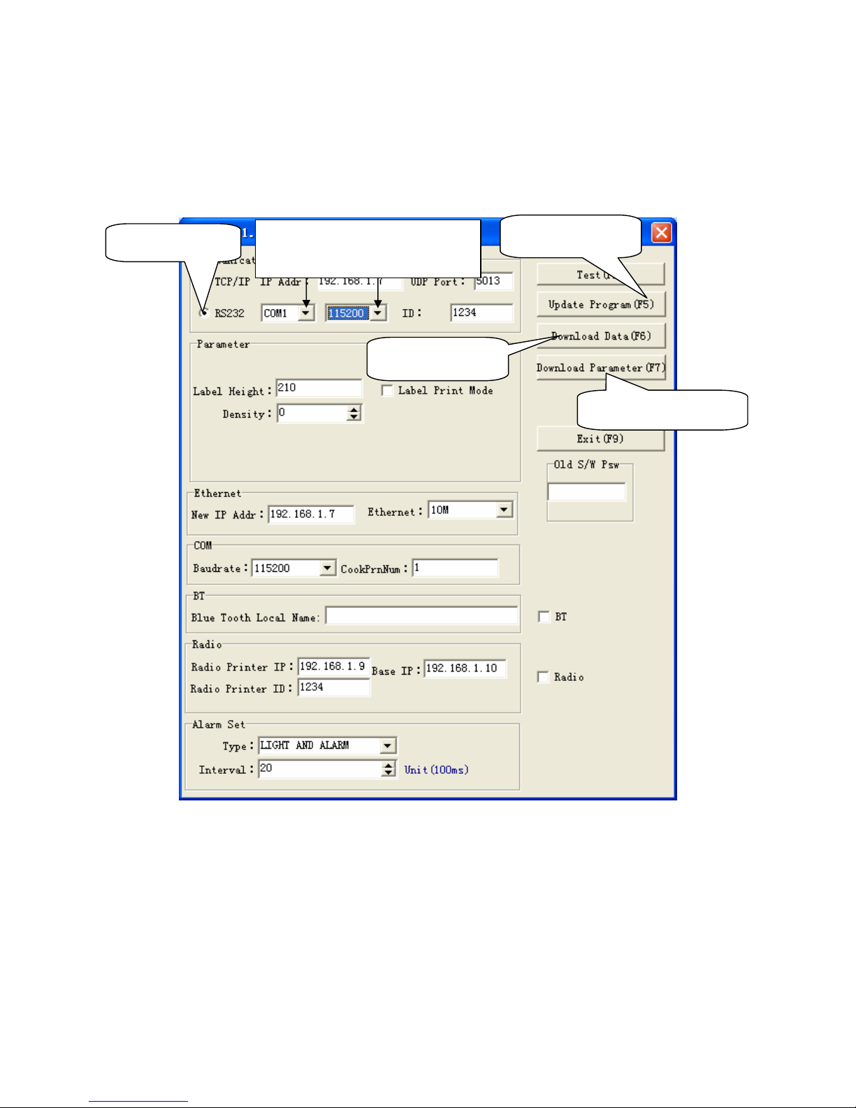
In the disk, you can find the software ‘PP7_en.exe’ in the file folder ‘PC-SW’, double click to open it.
Here, you can use the software to update program and download data.
Connect PP7X to PC.
Note: ① The available baud rate for this printer is 9600, 19200, 38400, 115200, 460800.
② The printer program can be updated at any baud rate.
③ ‘Download Data’, means download font. Please set the parameter in the left column if choose this item.
Press ‘F6’ on the keyboard, and then choose the file in the FONT file folder.
④ ‘Download Parameter’, means download parameter. After set the parameter, press ‘F7’ on the
keyboard, and then choose the file in the Parameter file folder.
⑤ The baud rate (9600,19200,38400,115200) and the print density can be changed via Dip Switch, please
refer to Chapter 13 for detail.
Update program
Download font
Download parameter
Choose RS232
Choose the correct port and
baud rate
Page 38
35
12 MODEL: PP7XWB
The communication distance of PP7XWB is up to 10m without obstacle.
12.1 BT Driver Installation
z Method 1:
This method is suitable for windows XP/VISTA OS.
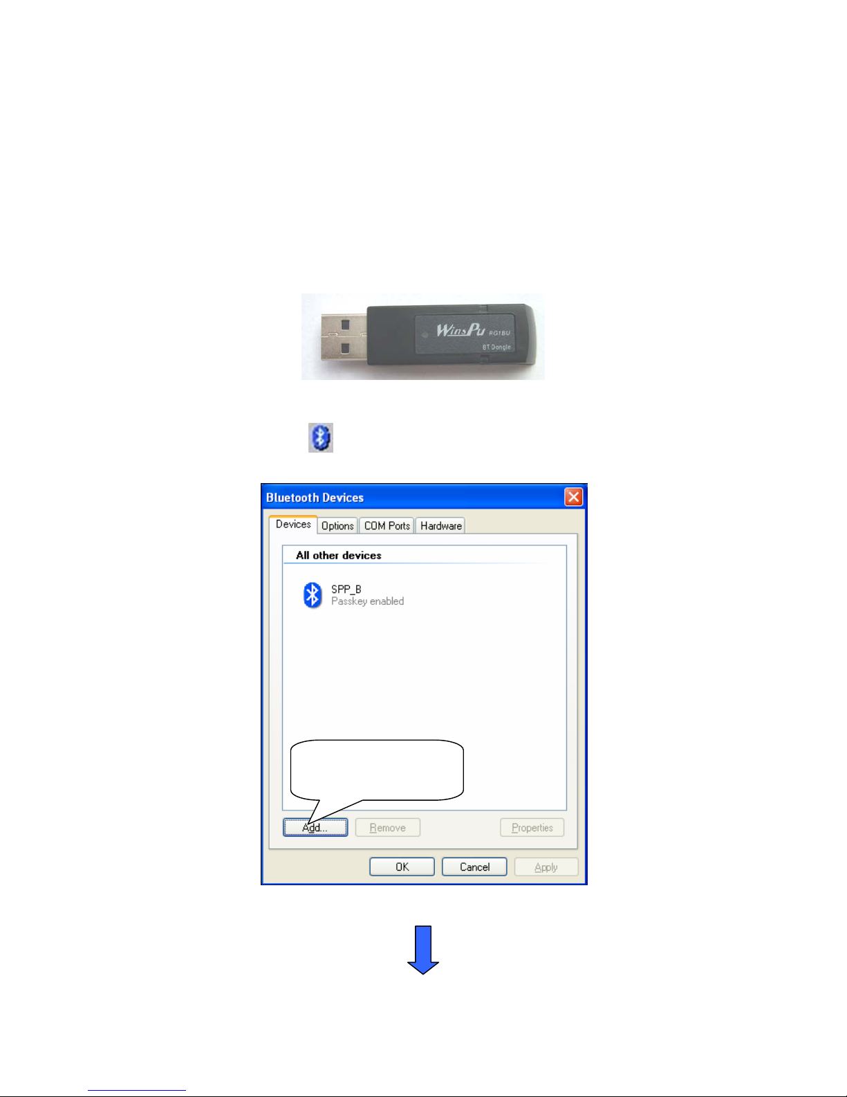
In the package, you can find a BT dongle.
If you will connect the PP8X printer to the PC, insert this dongle into the USB port of PC. The lower right
corner of screen will show the icon
, double click it.
Click this button to
add device.
Page 39
36
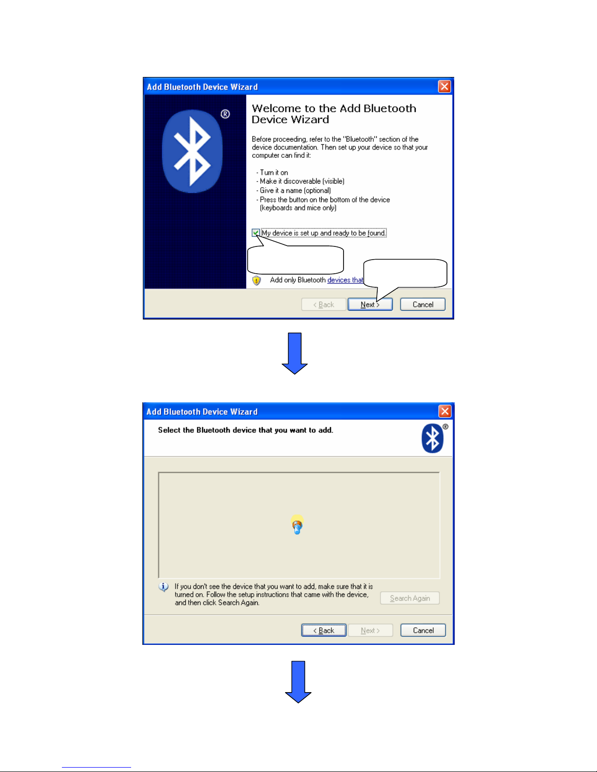
Select this item
Click ‘Next’
Page 40
37
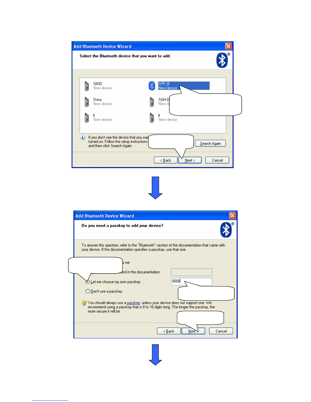
Choose the BT device
that you want to add.
Click ‘Next’
Choose this item
Set password here
Click ‘Next’
Page 41
38
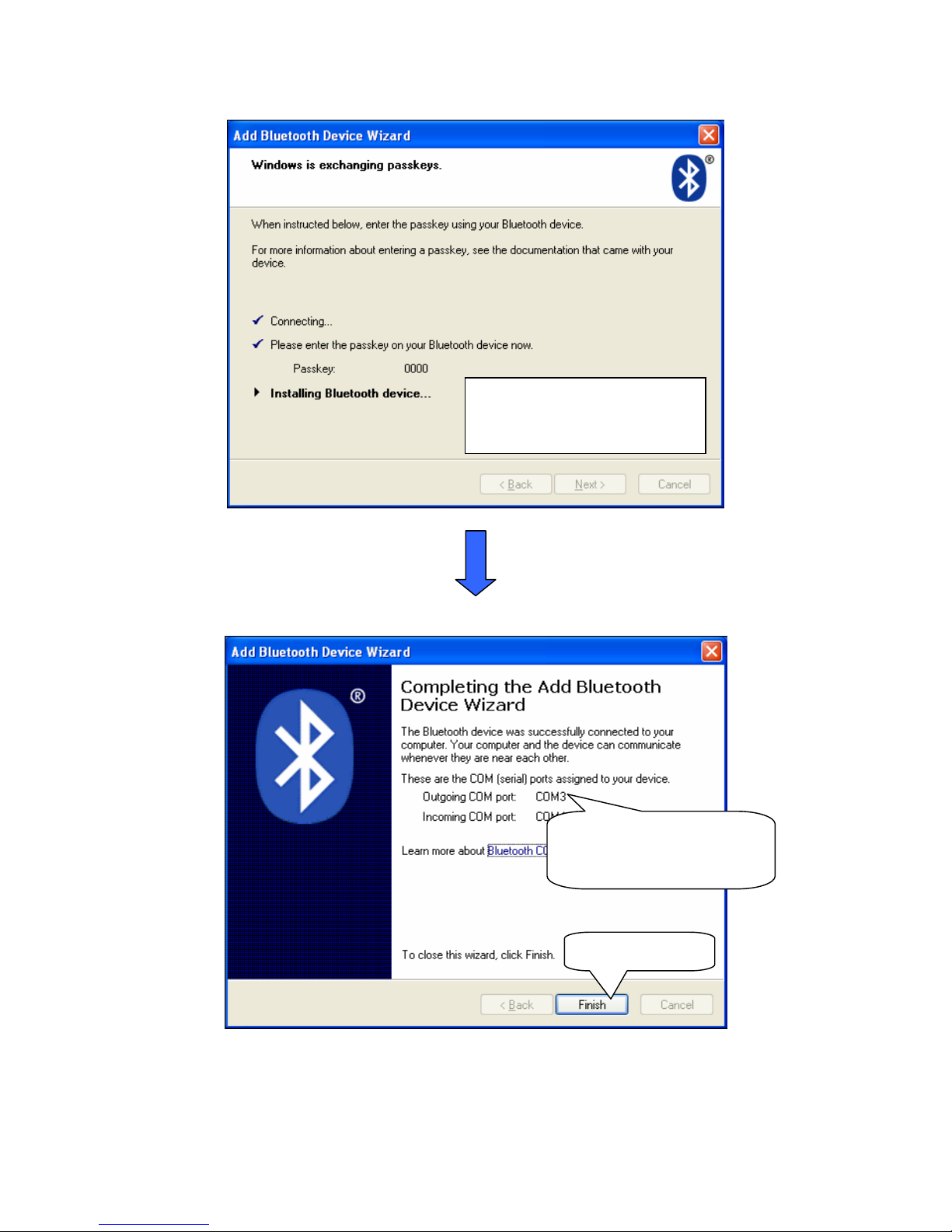
Installing the BT device
automatically
Here shows the connecting
port is COM3.
Click ‘Finish’
Page 42
39
z Method 2:
This method is suitable for windows 98/2000/XP/VISTA OS
If your operating system is windows 98 or windows 2000, you must install the BT driver first. And if your
operating system is window XP or VISTA, the system has the driver itself, no need to install it again.
If the 5M limit appeared during installing, please download the genuine driver in this address:
http://www.bluesoleil.com/download/
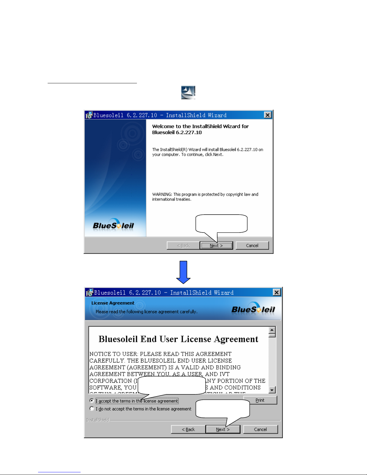
1. Open the file ‘IVT BlueSoleil’, double click the icon
to install the BT driver.
Click ‘Next’
Choose this item
Click ‘Next’
Page 43
40
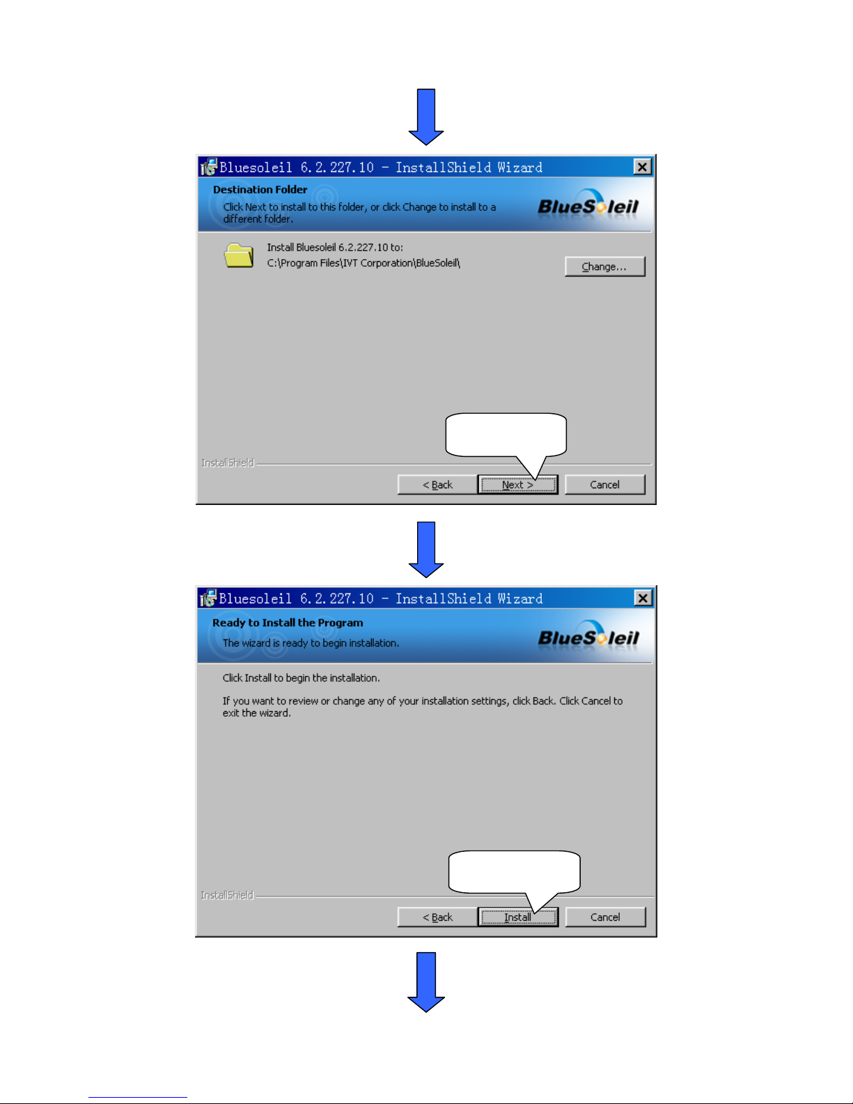
Click ‘Next’
Click ‘Install’
Page 44
41
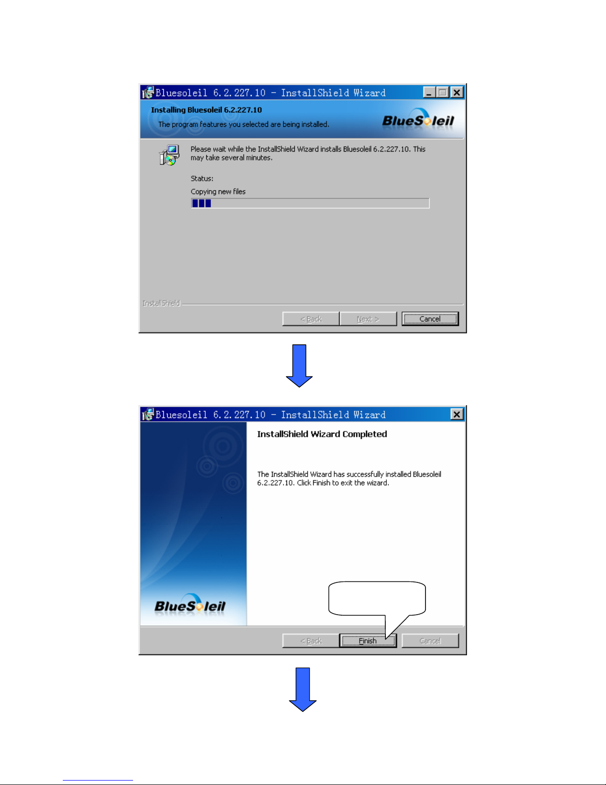
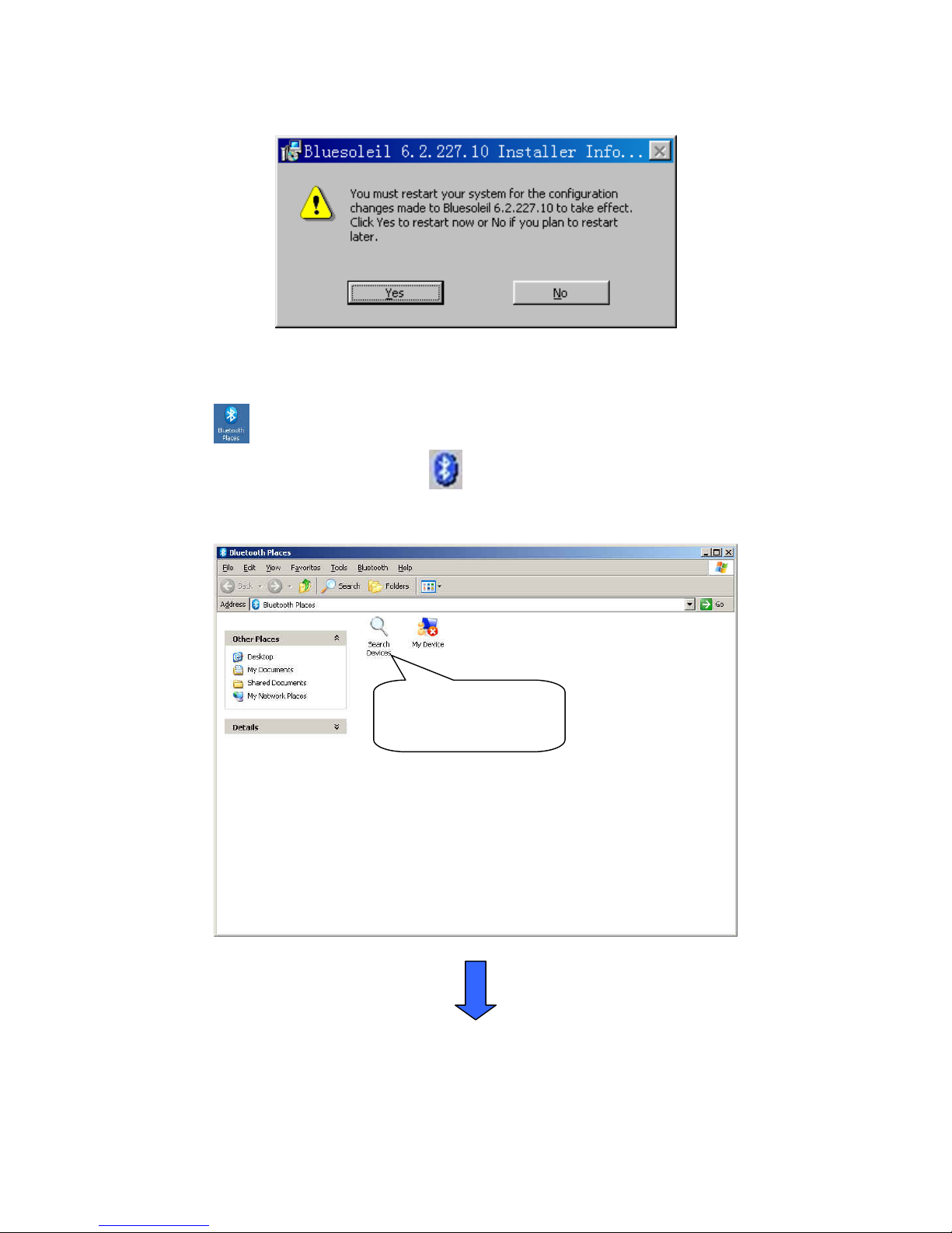
Click ‘Finish’
Page 45
42
2. After installing the BT driver, you need to match the BT. Insert the BT dongle into USB port of PC, double
click the icon
.
Note: if the icon is gray, right click the icon
at the right bottom of the window, choose the item
‘Turn on Bluetooth’.
Double click it to
search.
Page 46
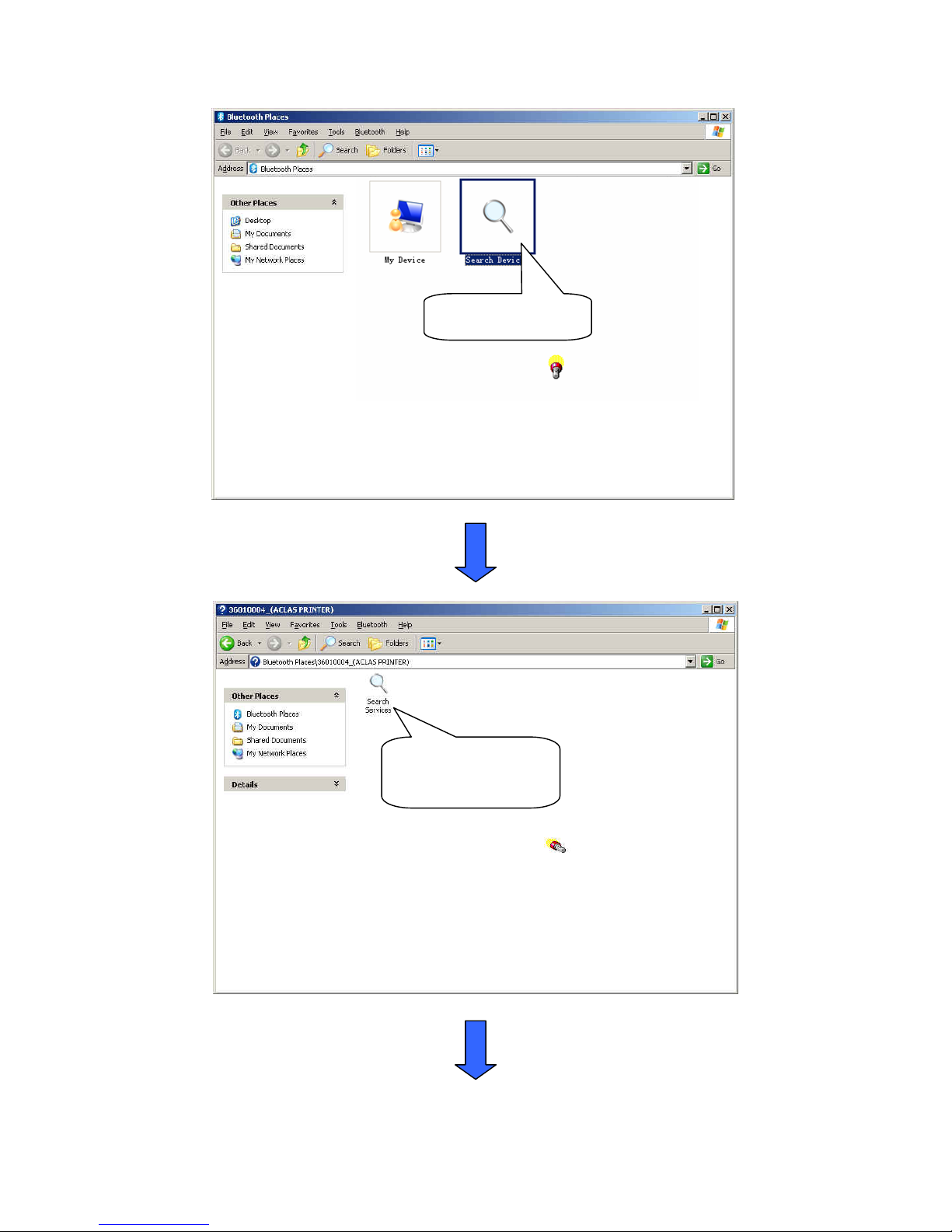
43
Double click it to
search.
Double click it.
Page 47
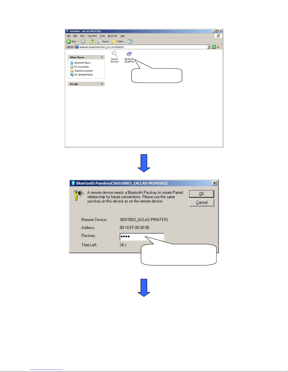
44
Double click it.
Input the passkey ‘0000’ to
create paired relationship.
Page 48
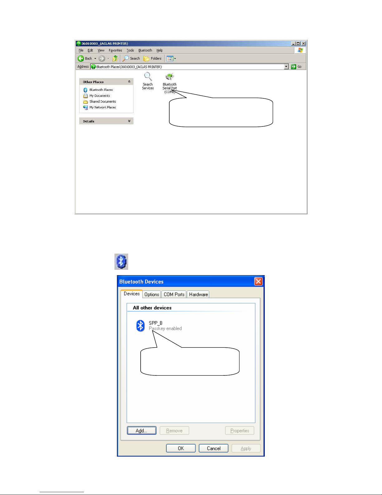
45
12.2 How to Know the Connecting Port
After installing the driver, you can follow the steps below to know which port is connected.
Double click the icon .
Here shows the BT device
you have installed
Here you can see the bluetooth
serial port is COM8.
Page 49
46
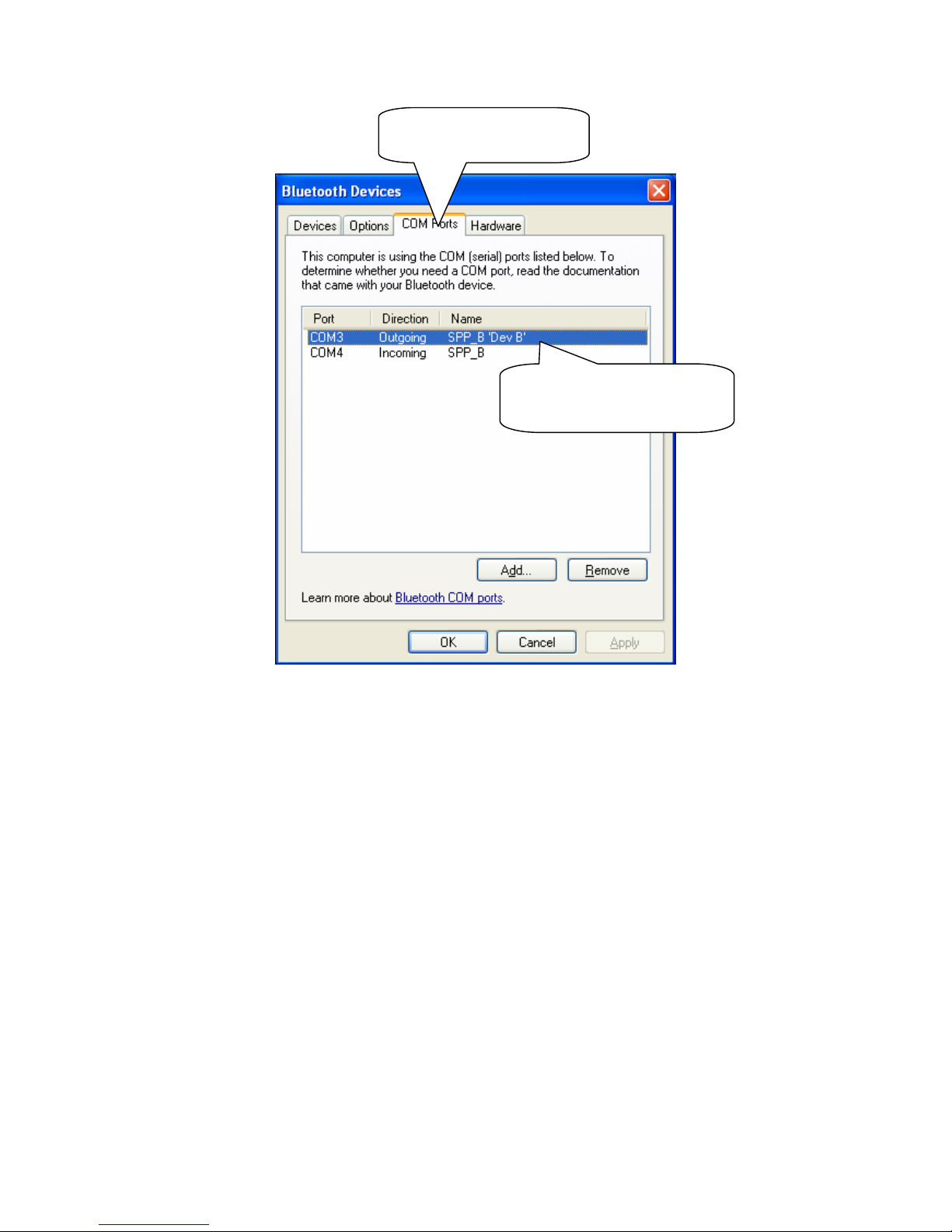
12.3 Printer Driver Installation
Connect the PP7X to PC. Click ‘Aclas printer.exe’ on the CD-disk, which is packed along with your
computer.
And then install the printer driver, please refer to chapter 7.1 for details, and choose the printer port as the
connecting port shows in Chapter 12.2 when you are install the driver.
Choose the ‘COM Ports’
Here shows the connecting
port is COM 3
Page 50
47
12.4 Software Description
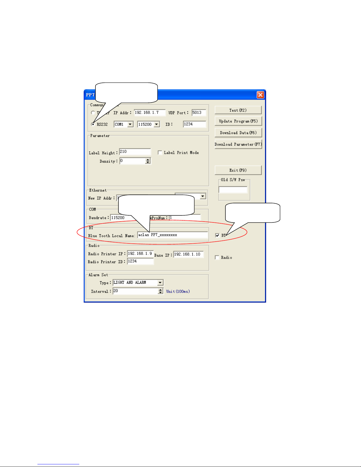
In the disk, you can find the software ‘PP7_en.exe’ in the file ‘PC-SW’, double click to open it.
Here, you can use the software to update program and download data.
Connect PP7X to PC.
Note: ① The available baud rate for this printer is 9600, 19200, 38400, 115200, 460800.
② The printer program can be updated at any baud rate.
③ ‘Download Data’, means download font. Please set the parameter in the left column if choose this item.
Press ‘F6’ on the keyboard, and then choose the file in the FONT file folder.
④ ‘Download Parameter’, means download parameter. After set the parameter, press ‘F7’ on the
keyboard, and then choose the file in the Parameter file folder.
⑤ After start the BT printer for about 6 seconds, it will print out the information of its system version,
machine code, and BT name, etc.
⑥ The baud rate (9600,19200,38400,115200) and print density can be changed via Dip Switch, please
refer to Chapter 13 for detail.
Choose RS232
Input the BT name.
Tick up BT.
Page 51
48
13 DIP SWITCH
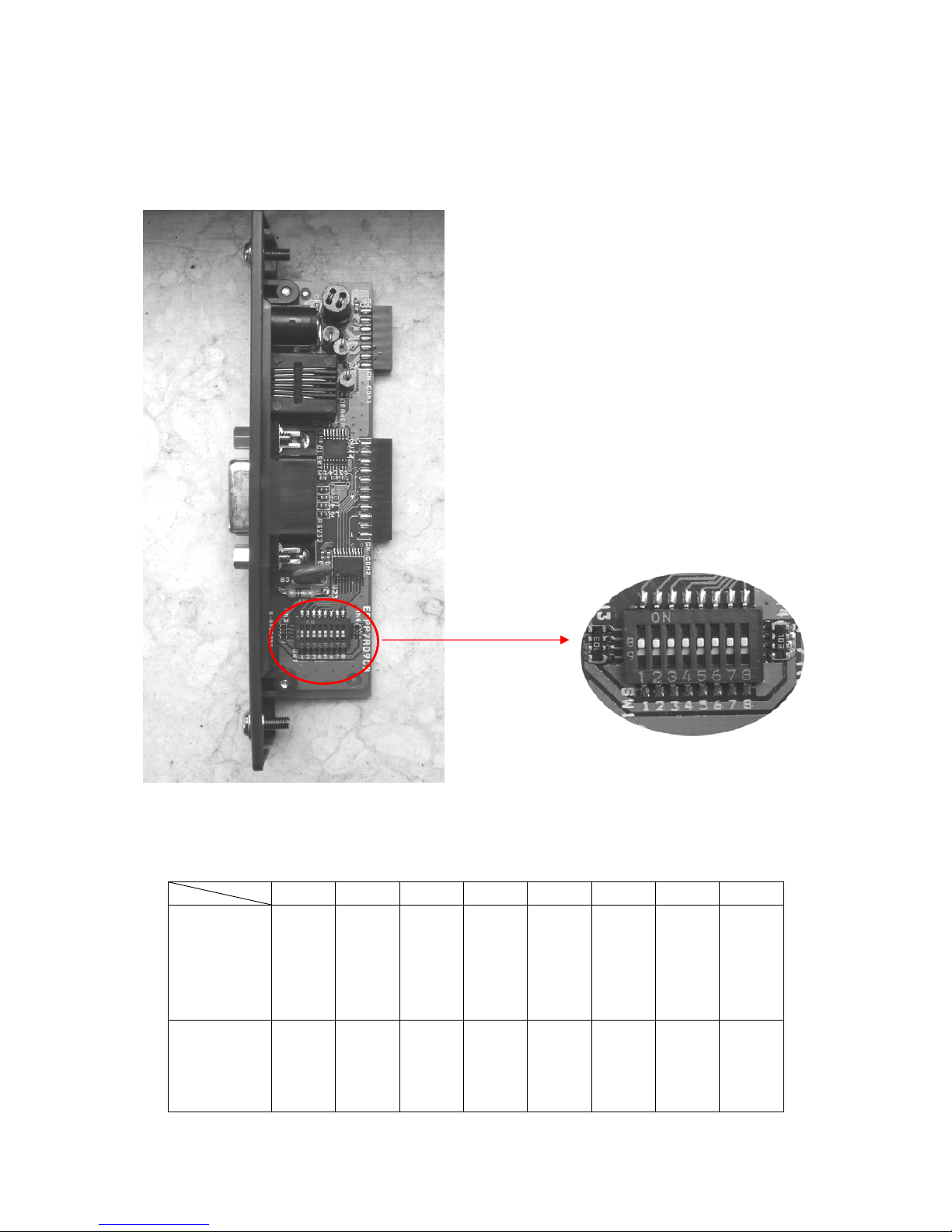
¾ The communication port module is with dip switch, please refer to the picture below:
¾ There are 8 switches altogether. Some of the printer’s function or parameter can be set via adjust
SW-1~ SW-8. the table below is the default setting when leave factory.
SW-1 SW-2 SW-3 SW-4 SW-5 SW-6 SW-7 SW-8
Parallel port
Ethernet
USB
2.4G P-tooth
433
ON ON ON ON
OFF
ON ON ON
8P
6P
D9
BT
ON ON ON ON
OFF
ON
OFF OFF
The Dip Switch
Page 52
49
Note:
1. Parallel port, Ethernet, USB, 2.4G P-tooth, and 433MHz wireless, the switch of these communication
boards are ON, except SW-5 is OFF;
2. BT, P8, P6, and D9, the switch of these communication boards are ON, except SW-5, SW-7, and SW-8
are set as OFF;
3. SW-7 and SW-8 are set as OFF, it indicates the baud rate is 115200;
4. SW-5 is OFF and SW-6 is ON, it indicates the print density is Class 2.
¾ There are 8 Dip Switch altogether, each switch has its own function, please refer to the diagram
below:
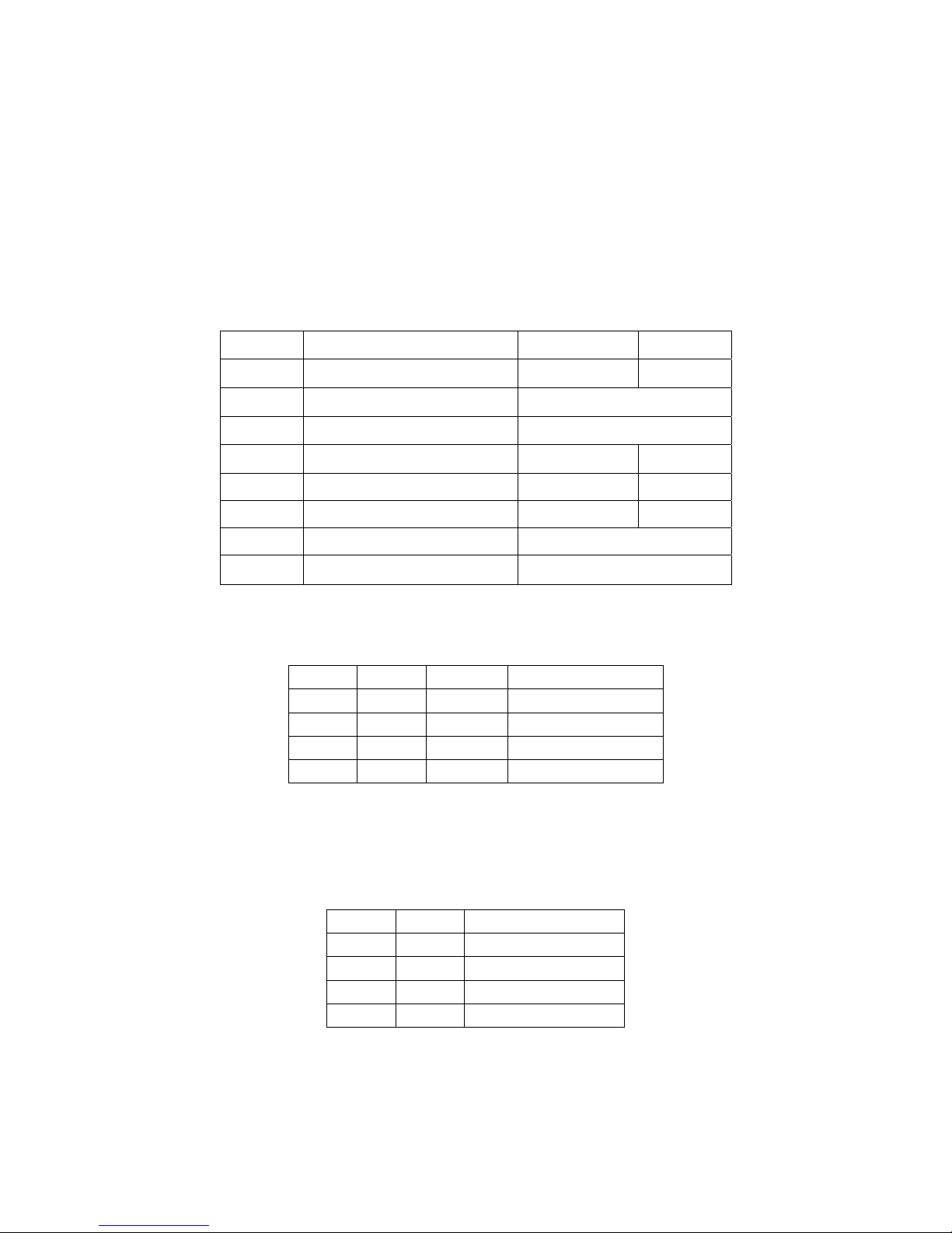
a) SW-5 and SW-6 are used to set print density, the on/off status of SW-5 and SW-6 is able to compose
differernt desity. Please refer to the table below:
SW-5 SW-6 Heat Time Density
ON ON 600us Dark
ON OFF 500us Middle Dark
OFF ON 420us Middle Light
OFF OFF 360us Light
NOTE: We suggest that you should not select ‘dark’ density level, or it may reduce the life time of the
printer head for 15%.
b) SW-7 and SW-8 are used to control baudrate, the on/off status of SW-7 and SW-8 is able to compose
diferent baudrate. Please refer to the diagram below:
SW-8 SW-7 Baudrate
ON ON 9600
ON OFF 19200
OFF ON 38400
OFF OFF 115200
NOTE:
1) As for the Dip Switch is relatively tiny, yet we need some tools that are relatively tiny to switch them,
for example, the head of ball pen or pencil.
2) Press key ‘Feed’ and hold it, and start the machine at the same time, it will print a piece of Test Page.
The function of the dip switch is based on the information of this Test Page.
DIP-8 Function ON OFF
SW-1 Select cutter Yes No
SW-2 Reserve
SW-3 Reserve
SW-4 Select RS232 HandShaking Yes No
SW-5 Select print density Light Dark
SW-6 Select print density Light Dark
SW-7 Select baudrate
SW-8 Select baudrate
Page 53

50
14 COMMANDS
The command explanations include the following parts:
1) Name and the general description of the command’s function---This is the first part for the command
description; it presents the command’s ASCII code format and general description of its function.
2) Format---This part used ASCII coding form, decimal code, and hex code to describe the command.
3)(Parameter) Range---This part gives the range of the variable. If there is special explanation, it should be the
decimal value. E.g. 1 ≤ n ≤ 4,in which the number ‘1’ is the decimal value, but the ASCII coding form.
4) Description---This part is to explain the command in detail.
5) Note---This part gives the attention items of the command. As the commands may interfere with each other
when they are used in different modes or when they co-work with different commands, yet this part gives the
details for these attention items.
Command Decimal Hex Function
LF 10 0A Print and line feed
FF 12 0C Print and recover to page mode
CAN 24 18 Cancel print data in page mode
CR 13 0D Print and carriage return
ESC FF 27 12 1B 0C Print data in page mode
ESC \ 27 92 1B 5C Specify relative position
ESC S 27 83 1B 53 Select standard mode
ESC T 27 84 1B 54 Select character print direction in page mode
ESC ! 27 33 1B 21 Select print mode(s)
ESC - 27 45 1B 2D Turn underline mode on/off
ESC { 27 123 1B 7B Turn upside-down printing mode on/off
ESC 2 27 50 1B 32 Select default line spacing
ESC 3 27 51 1B 33 Set line spacing
ESC D 27 68 1B 44 Set horizontal tab positions
HT 9 09 Horizontal tab
ESC SP 27 32 1B 20 Set right-side character spacing
ESC J 27 74 1B 4A Print bitmap lattice data, and feed n lines
ESC L 27 76 1B 4C Select page mode
ESC $ 27 36 1B 24 Set absolute print position
ESC W 27 87 1B 57 Set printing area in page mode
ESC @ 27 64 1B 40 Initialize printer
ESC = 27 61 1B 3D Select printer on or off
ESC * 27 42 1B 2A Select bit-image mode
ESC v 27 118 1B 76 Transmit paper sensor status
DLE EOT 16 4 10 04 Transmit real-time state
FS ! 28 33 1C 21 Set Chinese characters mode
FS S 28 83 1C 53 Set Chinese character space amount
ESC i 27 105 1B 69 Execute partial-cut
GS V 29 86 1D 56 Select paper-cut mode and cut paper
ESC p 27 112 1B 70 Bring impulse
Page 54
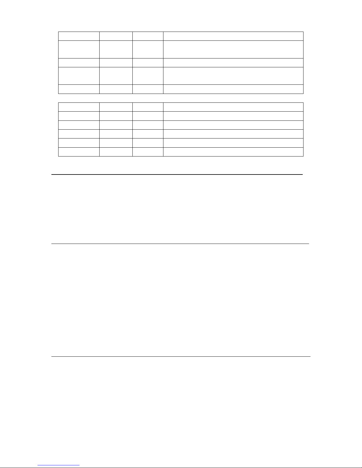
51
GS ! 29 33 1D 21 Select character size
GS $ 29 36 1D 24
Specify absolute position for character vertical direction
in page mode
GS L 29 76 1D 4C Set left margin
GS \ 29 92 1D 5C
Specify relative position for character vertical direction
in page mode
GS P 29 80 1D 50 Set basic calculated pitch
Command Decimal Hex Function
GS H 29 72 1D 48 Select printing position of HRI characters
GS h 29 104 1D 68 Set bar code height
GS w 29 119 1D 77 Set bar code width
GS k 29 107 1D 6B Print bar code
ESC t 27 116 1B 74 Select character code table
z LF Print and line feed
Format: ASCII LF
Decimal 10
Hex 0A
Note:
1. LF prints the data in the print buffer and fed per line based on the current line space.
2. Print characters with CR command.
z FF Print and recover to page mode
Format: ASCII FF
Decimal 12
Hex 0C
Description: Prints all buffered data to the print region collectively, then recovers to the standard mode.
Note:
∗ All buffer data is deleted after printing.
∗ The print area set by ESC W (Set print region in page mode) is reset to the default setting.
∗ No paper cut is executed.
∗ Sets the print position to the beginning of the next line after execution.
∗ This command is enabled only in page mode.
Reference: ESC FF, ESC L, ESC S
z CAN Cancel
Format: ASCII CAN
Decimal 24
Hex 18
Description: Deletes all print data in the currently set print region in page mode.
Note:
.
∗ This command is enabled only in page mode.
∗ Portions included in the currently set print region are also deleted, even if previously set print region data.
Reference: ESC L, ESC W
Page 55

52
z CR Print and carriage return
Format: ASCII CR
Decimal 13
Hex 0D
Note:
1. Set the print position to the beginning of the line.
2. Print characters with LF command.
z ESC FF print data in page mode
Format: ASCⅡ ESC FF
Decimal 27 12
Hex 1B 0C
Description: Prints all buffered data in the print area collectively in page mode.
Note:
∗ This command is enabled only in page mode.
∗ Holds the following information after printing.
a. Expanded data
b. Character print direction selection in page mode (ESCT)
c. Set print region (ESCW) in the page mode.
d. Character expansion position
Reference: FF, ESCL, ESCS
z ESC \ nL nH Specify relative position
Format: ASCⅡ ESC FF
Decimal 27 92
Hex 1B 5C
Range: 0 ≤ nL ≤ 255, 0 ≤ nH ≤ 255
Description: Specifies the next print starting position with a relative position based on the current position. This
sets the position from the current position to [(nL + nH x 256) x basic calculated pitch] for the next print starting
position.
Note:
∗ Specifications exceeding the print range are ignored.
∗ If the right direction of the current position is specified for the character direction, specify a positive number;
if the left direction is specified, a negative number is used.
∗ Negative numbers is represented by the complement of 65536. For example, when moving in the left direction
n pitches, use: nL + nH × 256 = 65536-N
∗ The basic calculated pitch is set by GSP (basic calculated pitch setting).
∗ If there are fractions in the result, correct to the minimum mechanical pitch and discard.
∗ Use the basic calculated pitch (x) for the horizontal direction in standard mode.
∗ The following operations occur according to the starting point in page mode.
a. If the starting point is set to upper left or lower right by the ESC T (Select character print direction in page
mode) command, specify the relative position of the vertical direction in the paper feed. Use the basic
calculated pitch (x) for the horizontal direction at this time.
b. If the starting point is set to upper right or lower left by the ESC T (Select character print direction in page
mode) command, move the print position in the paper feed direction. Use the basic calculated pitch (y) for
the horizontal direction at this time.
Page 56

53
Reference: ESC $, GS P
z ESC S Select standard mode
Format: ASCⅡ ESC FF
Decimal 27 83
Hex 1B 53
Description: Switches from page mode to standard mode.
Note:
∗ Valid only when input by page mode.
∗ All buffer data in page mode is deleted.
∗ Sets the print position to the beginning of the next line after execution.
∗ The print area set by ESCW (Set print region in page mode) is reset to the default setting.
∗ This command switches the settings for the following commands the values of which can be set independently
in standard mode and page mode to those for standard mode
a. ESC SP :Set character right space amount
b. FS S :Set Chinese character space amount
c. ESC 2 :Set default line spacing
d. ESC 3 :Set line feed amount
∗ The following commands are effective only when in standard mode.
a. ESC W :Set print region in page mode
b. ESC T :Select character print direction in page mode
∗ The following commands are ignored in standard mode.
a. GS S :Specify absolute position for character vertical direction in page mode
b. GS \: :Specify relative position for character vertical direction in page mode
∗ Standard mode is selected when the power is turned on, the printer is reset or initialized (ESC @).
Reference: FF, ESC FF, ESC L
z ESC T Select character print direction in page mode
Format: ASCⅡ ESC FF
Decimal 27 84
Hex 1B 54
Range: 0 ≤ n ≤ 3, 48 ≤ n ≤ 51
Initial Value: n = 0
Description:
Selects the character printing direction and starting point in page mode.
n
Print Direction Starting Point
0, 48 Left to Right Upper Left (A in the figure below)
1,49
Bottom to Top Lower Left (B in the figure below)
2,50
Right to Left Lower Right (C in the figure below)
3,51
Top to Bottom Upper Right (D in the figure below)
Page 57

54
Note:
∗ Executes only a printer internal flag operation when this command is input in standard mode. The command
does not affect printing in standard mode.
∗ The character expansion starting point is in the print region specified by ESC W (Set print region in page
mode).
∗ The basic calculated pitch (x or y) used with the following commands differs according to the starting point.
a. If the starting point is upper left or lower right (feeds paper and expands characters in the vertical direction)
Commands using x : ESC SP, ESC $, ESC \, FS S
Commands using y : ESC 3, ESC J, GS $, GS \
b. If the starting point is upper right or lower left
Commands using x : ESC 3, ESC J, GS $, GS \
Commands using y : ESC SP, ESC $, ESC \, FS S
Reference: ESC $, ESC L, ESC W, ESC \, GS $, GS P, GS\
z ESC ! Select print modes
Format: ASCⅡ ESC ! n
Decimal 27 33 n
Hex 1B 21 n
Note:
ESC !n selects print modes using n as follows. The default character font depends on the DIP switch
setting. The defaults for other print modes are set to n=0
X X D5 D4 X X X X
z ESC - Turn underline mode on/off
Format: ASCⅡ ESC - n
Decimal 27 45 n
Hex 1B 2D n
Range: 0≤n≤1
0: turn underline mode off
1: turn underline mode on
1: Double-height mode
1: Double-wide mode
Page 58

55
z ESC { Turn upside-down printing mode on/off
Format: ASCⅡ ESC { n
Decimal 27 123 n
Hex 1B 7B n
Range: 0≤n≤255
ESC { n turns upside-down printing mode on or off. When the LSB (least significant bit) of n is 1,
upside-down printing mode is turned on; when it is 0, upside-down printing mode is turned off. The default
setting is n=0. When upside-down mode is turned on, the printer prints 180°-rotated characters from right to left.
The line printing order is not reversed; therefore, be careful of the order of the data transmitted. In standard
mode, this command is enabled only when processed at the beginning of a line. In page mode, an internal flag is
activated and this command is enabled when the printer returns to standard mode.
z ESC 2 Select default line spacing
Format: ASCⅡ ESC 2
Decimal 27 50
Hex 1B 32
Description: Sets line feed amount per one line to approximately 4.23 mm (1/6 inch).
Note: Line spacing can be set independently for both the standard and page modes.
Reference: ESC 3
z ESC 3 Set line spacing
Format: ASCⅡ ESC 3 n
Decimal 27 51 n
Hex 1B 33 n
Range: 0≤n≤255
Description: Sets the line space for one line to [n x basic calculated pitch].
Note:
∗ ESC 3 n sets the line spacing to n×(vertical or horizontal motion unit). The default setting of the paper feed
amount is 1/6 inch (n=60). The maximum line spacing amount is 40 inches. When standard mode is selected,
the vertical motion unit set by GS P is used. When page mode is selected, the vertical or horizontal motion unit
set by GS P is used for the print direction set by ESC T.
∗ The line spacing can be set independently in standard mode and in page mode.
∗ The basic calculated pitch is set by GSP (Set basic calculated pitch). Also, after setting the line space, it is not
affected even if the basic calculated pitch is changed.
∗ If the calculation results in fractions, the pitch is corrected to a minimal mechanical pitch and the rest is
discarded.
∗ In standard mode, the basic calculated pitch (y) for the vertical direction is used.
∗ In page mode, the basic calculated pitch that is used according to the starting point varies.
a. When the starting point is specified to be upper left or lower right by the ESC T command (Character print
direction selection in page mode), the basic calculated pitch (x) for the horizontal direction is used.
b. When the starting point is specified to be upper right or lower left by the ESC T command (Character print
direction selection in page mode), the basic calculated pitch (y) for the horizontal direction is used.
∗ The maximum value that can be set for the line space is approximately 1,016mm (or 40 inches). Specifications
that exceed the maximum value are rounded off to that value.
Reference: ESC 2, GS P
Page 59

56
z ESC D Set horizontal tab positions
Format: ASCⅡ ESC D n1 … nk NUL
Decimal 27 68 n1 … nk 00
Hex 1B 44 n1 … nk 0
Range: 1≤n≤255
0≤k≤32
Description: ESC D n1 … nk NUL sets a horizontal tab position to n columns from the beginning of a line,
with k indication the total number of horizontal tab positions to be set. When a left margin is set in standard
mode, the position of the left margin is the beginning of the line. A maximum of 32 tab positions can be set.
This command cancels any previous horizontal tab settings. The default tab positions are every eight characters
for the font A (12×24).
Note: The character width is stored for standard and page modes.
Reference: HT
z HT Horizontal tab
Format: ASCII HT
Decimal 9
Hex 09
Description: Moves the print position to the next horizontal tab position.
Notes: This command is ignored unless the next horizontal tab position has been set.
If the next horizontal tab position exceeds the printing area, the printer sets the printing position to [printing
area width + 1].
Horizontal tab positions are set with ESC D.
If this command is received when the printing position is at [printing area width + 1], the printer executes
print bufferfull printing of the current line and horizontal tab processing from the beginning of the next line.
Please refer to ESC D
z ESC SP n Set right-side character spacing
Format: ASCII ESC SP n
Decimal 27 32 n
Hex 1B 20 n
Range: 0 ≤ n ≤ 255
ESC SP n sets the right-side character spacing to n ′ (horizontal or vertical motion unit). It is used to
change the spacing between characters. The default setting is n=0. When standard mode is selected, the
horizontal motion unit set by GS P is used. When page mode is selected, the vertical or horizontal motion unit
set by GS P is used for the print direction set by ESC T.
This command is effective for all characters (except for HRI characters).
z ESC J Print and feed paper
Format: ASCⅡ ESC J n
Decimal 27 74 n
Hex 1B 4A n
Range: 0≤n≤255
Description: ESC J n prints the data in the print buffer and feeds the paper n×(vertical or horizontal motion
unit). This command is used to temporarily feed a specific length without changing the line spacing set by other
commands. The maximum paper feed amount is 40 inches. When standard mode is selected, the vertical motion
Page 60

57
unit set by GS P is used. When page mode is selected, the vertical or horizontal motion unit set by GS P is used
fro the print direction set by ESC T.
Note:
∗ In standard mode, the basic calculated pitch (y) for the vertical direction is used.
∗ In page mode, the basic calculated pitch that is used according to the starting point varies.
a. When the starting point is specified to be upper left or lower right by the ESC T command (Character print
direction selection in page mode), the basic calculated pitch (x) for the horizontal direction is used.
b. When the starting point is specified to be upper right or lower left by the ESC T command (Character print
direction selection in page mode), the basic calculated pitch (y) for the horizontal direction is used.
∗ Paper is fed approximately 1016 mm if the [n x basic calculated pitch] exceeds approximately 1016mm (40
inches).
Reference: GS P
z ESC L Select page mode
Format: ASCⅡ ESC L
Decimal 27 76
Hex 1B 4C
Description: Switches from standard mode to page mode.
Note:
∗ Enabled only when input with the top of line.
∗ Invalid when input by page mode.
∗ Returns to standard mode after the following commands are issued.
a. FF (Print and recover to page mode)
b. ESC S (Select standard mode)
∗ Character expansion position has the starting point specified by ESC T (Character print direction selection in
page mode) in the printing region designated by the ESC W (Set print region in the page mode) command.
∗ This command switches the settings for the following commands the values of which can be set independently
in standard mode and page mode to those for page mode.
a. Set space amount: ESC SP, FS S
b. Set line feed amount: ESC 2, ESC 3
∗ The following commands are enabled only when in page mode.
a. ESC V :Specify/cancel character 90 degree clockwise rotation
b. ESC a :Position alignment
c. ESC { :Specify/cancel upside-down printing
d. GS L :Set left margin
e. GS W :Set print region width
∗ The following command is ignored in page mode.
a. GS (A :Test print
∗ The following commands are invalid in page mode.
a. FSp :Print NV bit image
b. FSq :Define NV bit image
c. FSg1 :Write data to user NV memory
d. GSv0 :Print raster bit images
∗ Recover to standard mode using ESC@ (initialize printer).
Reference: FF, CAN, ESC FF, ESC S, ESC T, ESC W, GS $, GS \
Page 61

58
z ESC $ Set absolute print position
Format: ASCⅡ ESC $ nL nH
Decimal 27 36 nL nH
Hex 1B 24 nL nH
Range: 0≤nL≤255
0≤nH≤255
Description: Specifies the next printing starting position using an absolute position based on the left margin
position. The next printing starting position is the position specified by [(nL+nH×256) × basic calculated pitch]
from the left margin position.
Note:
∗ Specifications exceeding the print range are ignored.
∗ The basic calculated pitch is set by GSP (Set basic calculated pitch).
∗ If the calculation results in fractions, the pitch is corrected to a minimal mechanical pitch and the rest is
discarded.
∗ In standard mode, the basic calculated pitch (x) for the horizontal direction is used.
∗ In page mode, the basic calculated pitch that is used according to the starting point varies.
a. When the starting point is specified to be upper left or lower right by the ESC T command (Character print
direction selection in page mode), the basic calculated pitch (x) for the horizontal direction is used.
b. When the starting point is specified to be upper right or lower left by the ESC T command (Character print
direction selection in page mode), the basic calculated pitch (y) for the horizontal direction is used.
Reference: ESC \ , GS $, GS \ , GS P
z ESC W Set printing area in page mode
Format: ASCⅡ ESC W xL xH yL yH dxL dxH dyL dyH
Decimal 27 87 xL xH yL yH dxL dxH dyL dyH
Hex 1B 57 xL xH yL yH dxL dxH dyL dyH
Range: 0≤xL, xH, yL, yH, dxL, dxH, dyL, dyH≤255
(except for dxL = dxH = 0 or dyL= dyH =0)
Description:
ESC W xL xH yL yH dxL dxH dyL dyH sets the size and position of the printing area in page
mode as follows:
Horizontal starting position = (xL + xH×256) (horizontal motion unit)
Vertical starting position = (yL + yH×256) (vertical motion unit)
Printing area width = (dxL + dxH×256) (horizontal motion unit)
Printing area height = (dyL + dyH×256) (vertical motion unit)
The default settings are as follows:
xL = 0, xH = 0, yL = 0, yH = 0
dxL = 0, dxH = 2, dyL = 126, dyH = 6
This command is enabled only in page mode. If this command is processed in standard mode, an internal flag
is activated and this command is enabled when the printer selects page mode.
The horizontal and vertical motion units use the horizontal and vertical values set by the GS P command. The
default settings of the horizontal and vertical motion units are 1/180 and 1/360 inches, respectively.
Note:
∗ In standard mode, the printer executes only internal flag operations with this command is input.
∗ If the horizontal direction starting point or vertical direction starting point is outside of the printable region, the
command is stopped and normal printing commences from subsequent data.
Page 62
59
∗ If the horizontal direction length or vertical direction length is 0, the command is stopped and normal printing
commences from subsequent data.
∗ The character expansion starting point is the point specified by selecting the character printing direction (ESC
T) in page mode in the print region.
∗ If (horizontal direction starting position + horizontal direction length) exceeds the printable region in the
horizontal direction, the horizontal direction length is set to (horizontal direction printable region - horizontal
direction starting point).
∗ If (vertical direction starting position + vertical direction length) exceeds the printable region in the vertical
direction, the vertical direction length is set to (vertical direction printable region – vertical direction starting
point).
∗ The basic calculated pitch is set by GSP (Set basic calculated pitch). Also, the set printing region is not
changed even if the basic calculated pitch is changed after setting the print region.
∗ If the calculation results in fractions, the pitch is corrected to a minimal mechanical pitch and the rest is
discarded.
∗ The basic calculated pitch (x) is used in the calculated pitch for the horizontal direction starting point and the
length in the horizontal direction; and the basic calculated pitch (y) is used in the calculated pitch for the
vertical direction starting point and the length in the vertical direction.
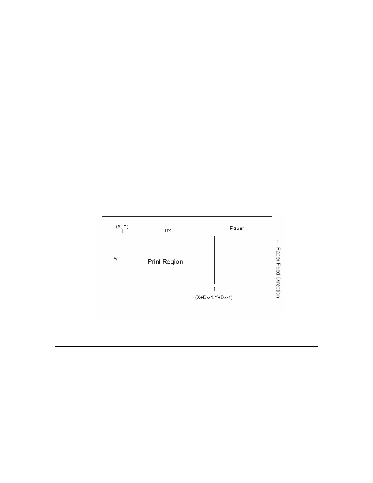
∗ The print region shown in the figure below when the horizontal direction starting is X; the vertical direction
starting point is Y; the horizontal direction length is Dx; and the vertical direction length is Dy.
Reference: CAN, ESC L, ESC T, GSP
z ESC @ Initialize printer
Format: ASCⅡ ESC @
Decimal 27 64
Hex 1B 40
ESC @ initializes the printer. All settings, including character font and line spacing settings, are canceled.
The data in the print buffer is cleared and the printer mode is reset to the mode that was in effect when the
power was turned on. The DIP switch settings are not checked again, the data in the receive buffer is not cleared,
and any macro definitions are not cleared.
Page 63
60
z ESC = n Select peripheral device
Format: ASCII ESC = n
Decimal 27 61 n
Hex 1B 3D n
Range: 0≤n≤255
ESC = n selects the device to which the host computer sends data, based on the value of n as follows:
Bit Off/On Hex Decimal Function
Off 00 0 Printer disabled
0
On 01 1 Printer enabled
1-7 - - - Undefined
When the LSB (least significant bit) of n is 1, the printer is enabled; when it is 0, the printer is disabled.
When the printer is disabled, it ignores all received data with the exception of DLE ENQ 1 and DLE ENQ 2.
The default setting is n. If ASB is enabled when the printer is disabled by ESC =, the printer transmits a 4-byte
status message whenever the status changes.
z ESC
* Select bit-image mode
Format: ASCII ESC * m nL nH d1 ... dk
Decimal 27 42 m nL nH d1 ... dk
Hex 1B 2A m nL nH d1 ... dk
Range: m=0, 1, 32, 33
0≤nL≤255
0≤nH≤3
0≤d≤255
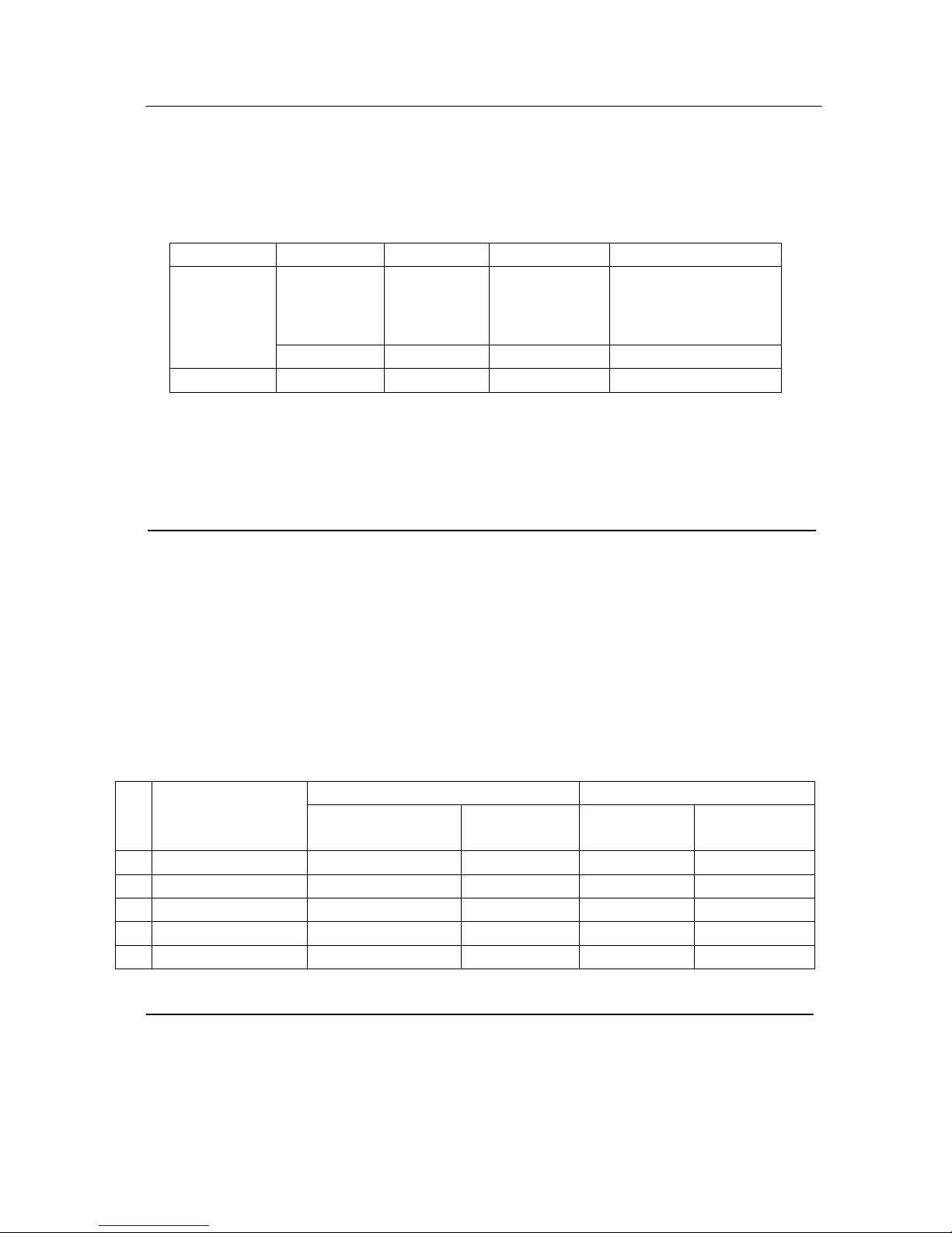
ESC * m nL nH d1 ... dk selects a bit-image mode using m for the number of dots specified by (nL +
nH×256). Set a bit to 1 to print a dot, or set a bit to 0 to not print a dot. d indicates the bit image data. The
modes selectable by m are as follows:
Vertical direction Horizontal direction
m Mode
Number of bits for
vertical data
Dot density
(DPI)
Dot density
(DPI)
Amount of data
(k)
0 8-dot single-density 8 68 101 192
1 8-dot double-density 8 68 203 384
2 24-dot single-density 24 203 101 192
33 24-dot double-density 24 203 203 384
39 24-dot double-density 24 203DPI 203DPI 384
z ESC v Transmit paper sensor status
Format: ASCII ESC v
Decimal 27 118
Hex 1B 76
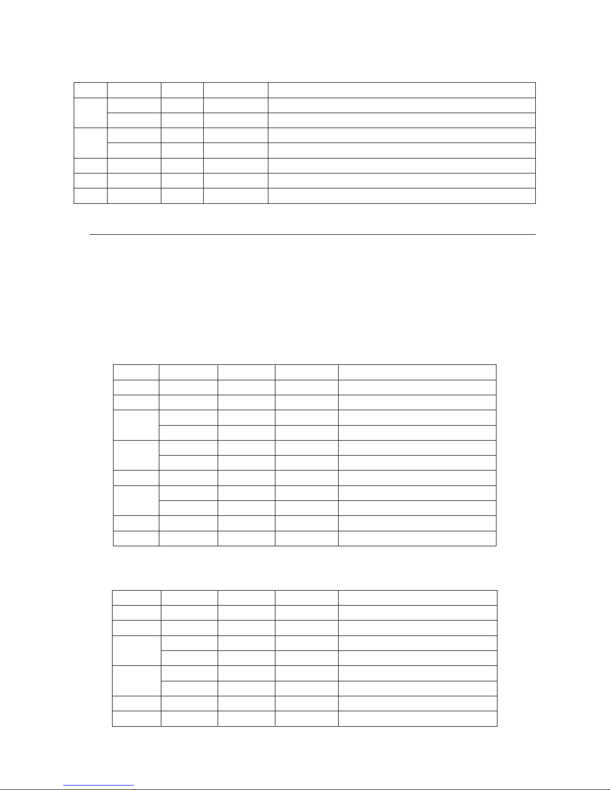
ESC v transmits the status of a paper sensor as 1 byte of data. This command allows the host to obtain the
near-end or paper-out status for each line. GS r 1 can also be used to check the status. GS r is recommended for
Page 64
61
transmitting the paper sensor status. The status to be transmitted is shown in the table below.
Bit Off/On Hex Decimal Status
Off 00 0 Paper roll near-end sensor: paper adequate.
0,1
On 03 3 Paper roll near-end sensor: paper near end.
Off 00 0 Paper roll end sensor: paper present.
On (0C) (12) Paper roll end sensor: paper not present.
4 Off 00 0 Not used. Fixed to Off.
5,6 - - - Undefined.
7 Off 00 0 Not used. Fixed to Off.
z DLE EOT n Transmit real-time state
Format: ASCII DLE EOT n
Decimal 16 4 n
Hex 10 04 n
Range: 1≤n≤4
Note: ① This command is only suitable for the printer model of serial port.
② Transmit the real-time state parameter n of the printer, in order to designate the deferent printer state,
define as follows:
n=1: transmit printer state;
Bit Off/On Hex Decimal Function
0 Off 00 0 Fixed to Off
1 On 02 2 Fixed to On
Off 00 0 Cash drawer open
2
On 04 4 Cash drawer closed
Off 00 0 Online
3
On 08 8 Offline
4 On 10 16 Fixed to On
Off 00 00 Not wait for online resume
5
On 20 32 Wait for online resume
6 - - - Undefined
7 Off 00 00 Fixed to Off
n=2: transmit offline state;
Bit Off/On Hex Decimal Function
0 Off 00 0 Fixed to Off
1 On 02 2 Fixed to On
Off 00 0 Upper cover closed
2
On 04 4 Upper cover open
Off 00 0 Not press paper feed key
3
On 08 8 Press paper feed key
4 On 10 16 Fixed to On
5 Off 00 00 Paper adequate
Page 65
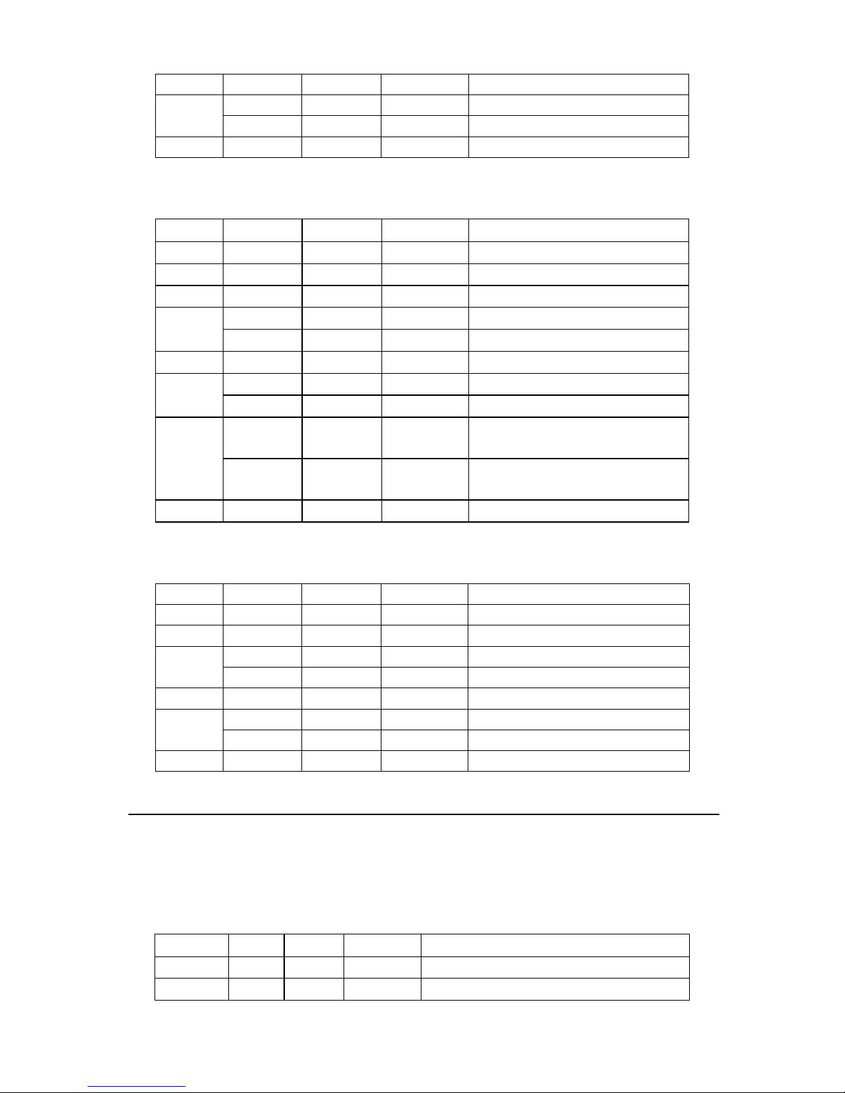
62
On 20 32 Printer no paper
Off 00 0 No error
6
On 40 64 Error
7 Off 00 0 Fixed to Off
n=3: transmit error state;
Bit Off/On Hex Decimal Function
0 Off 00 0 Fixed to Off
1 On 02 2 Fixed to On
2 - - Undefined
Off 00 0 Cut no error
3
On 08 8 Cut error
4 On 10 16 Fixed to On
Off 00 0 No beyond retrieve error
5
On 20 32 Beyond retrieve error
Off 00 0
Printer temperature and voltage
normal
6
On 40 64
Printer temperature or voltage over
range
7 Off 00 0 Fixed to Off
n=4: transmit paper roll sensor state;
Bit Off/On Hex Decimal Function
0 Off 00 0 Fixed to Off
1 On 02 2 Fixed to On
Off 00 0 Paper adequate
2, 3
On 0C 12 Paper near end
4 On 10 16 Fixed to On
Off 00 00 Paper adequate
5,6
On 60 96 Paper end
7 Off 00 0 Fixed to Off
z FS ! n Set Chinese characters printing mode compages
Format: ASCII FS ! n
Decimal 28 33 n
Hex 1C 21 n
Range: 0≤n≤255
Set the parameter n of Chinese characters printing mode as follows:
Digit 0/1 Hex Decimal Function
0, 1 - - Undefined.
2
0 00 0 Double-width mode not selected.
Page 66

63
1 04 4 Double-width mode selected.
0 00 0 Double-height mode not selected.
3
1 08 8 Double-height mode selected.
4-6 -- -- Undefined.
0 00 0 Underline not selected.
7
1 128 80 Underline selected.
z FS S n1 n2 Set Chinese character space amount
Format: ASCII FS S n1 n2
Decimal 28 83 n1 n2
Hex 1C 53 n1 n2
Range: 0≤n1≤255, 0≤n2≤255
Initial value: n1=0, n2=0
Description:
1. Sets the Chinese character space amount and right space amount.
2. Left space amount: n1 x (basic calculated pitch)
3. Right space amount: n2 x (basic calculated pitch)
Note:
∗ The space amount set by this command is the amount when using standard sized characters. When expanding
characters more than double in the horizontal direction, the space amount is [set amount x horizontal direction
magnification].
∗ Space amount can be set independently for both the standard and page modes.
∗ The basic calculated pitch is set by GSP (Set basic calculated pitch). Also, after setting the Chinese character
space amount, it is not affected even if the basic calculated pitch is changed.
∗ If there are fractions in the result, correct to the minimum mechanical pitch and discard.
∗ Use the basic calculated pitch (x) for the horizontal direction in standard mode.
∗ In page mode, the basic calculated pitch that is used according to the starting point is shown below.
a. When the starting point is specified to be upper left or lower right by the ESC T command (Character print
direction selection in page mode), the basic calculated pitch (x) for the horizontal direction is used.
b. When the starting point is specified to be upper right or lower left by the ESC T command, the basic
calculated pitch (y) for the vertical direction is used.
c. The maximum value for the left or right space for Chinese characters is approximately 35.893 mm (255/180
inches). Specifications that exceed the maximum value are rounded off to that value.
Reference: GSP
z ESC I Execute partial-cut (one point left uncut)
Format: <1B>H<69>H
Description: Execute a partial-cut of the paper.
z ①GS V m GS V m n② Select paper-cut mode and cutting paper
Format: ①ASCII GS V m
Hex 1D 56 m
Decimal 29 86 m
②ASCII GS V m n
Hex 1D 56 m n
Decimal 29 86 m n
Range: ① m = 0,48,1,49
Page 67
64
② m =65,66, 0 ≤n ≤255
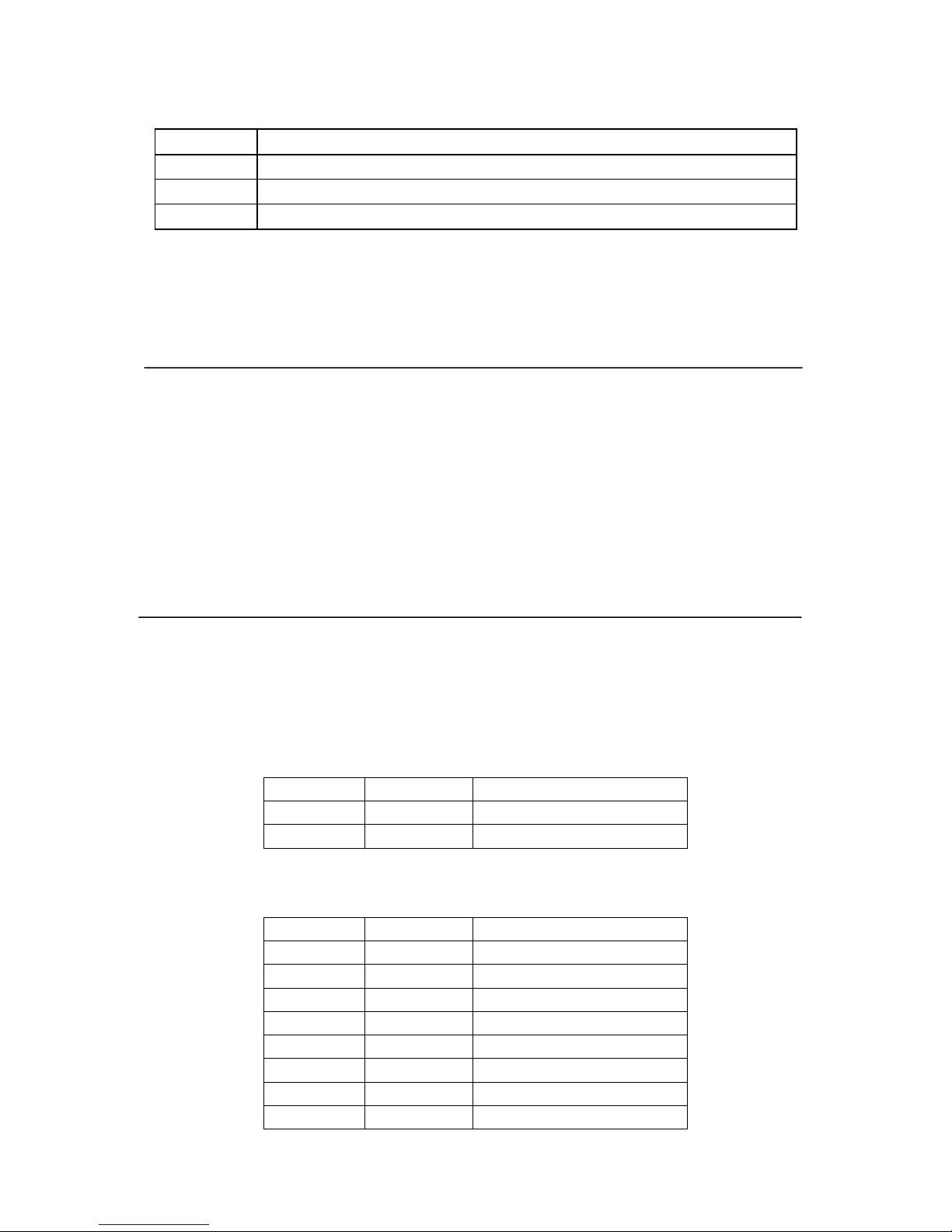
Paper-cut
M Paper-cut mode
0, 48 Full-cut
1, 49 Partial-cut
65,66 Feed paper ([n* (lengthways moving unit ) inch]) and partial-cut
● m = 0, 48, 1, 49, cutting paper directly.
● m= 65, 66, feeding paper [the distance between printing position and the paper cutter + n*(lengthways
moving unit)], and then cutting paper.
● Measuring the formfeed distance by lengthways moving unit
z ESC p m t1 t2 Bring impulse
Format: ASCII ESC p m t1 t2
Hex 1B 70 m t1 t2
Decimal 27 112 m t1 t2
Range: m = 0,48,1,49
0 ≤t1 ≤255
0≤t2 ≤255
● The time of getting impulse is [t1*2] millisecond, and the cutting time is [t2*2] millisecond.
● When t2 < t1, then printer disposing t1*2 millisecond.
● If t2 is less than 50, suppose t2 as 50.
z GS ! n Select character size
Format: ASCII GS ! n
Hex 1D 21 n
Decimal 29 33 n
Range: 0≤ n ≤ 255
GS ! n selects the character height using bits 0 to 3, and selects the character width using bits 4 to 7.
Character width selection is as follows:
Hex Decimal Width
00 0 1 (normal)
10 16 2 (double-width)
Character height selection is as follows:
Hex Decimal Height
00 0 1 (normal)
01 1 2 (double-width)
02 2 3
03 3 4
04 4 5
05 5 6
06 6 7
07 7 8
Page 68

65
Note:
∗ This command is effective for all characters (ANK and Chinese characters), excluding HRI characters.
∗ If the vertical and horizontal magnification ratios are outside the defined range, this command is ignored.
∗ In standard mode, the vertical direction is the paper feed direction; the horizontal direction traverses the paper
feed direction. Therefore, when character orientation changes in 90 degree clockwise rotation mode, the
relationship between vertical and horizontal directions is reversed.
∗ In page mode, vertical and horizontal directions are based on the character orientation.
∗ The base line for characters is the same when there are characters having different vertical direction ratios in
the same line.
∗ The ESC ! (Batch specify print mode) command can also turn double-width and double-height modes on or off,
but the setting of the last received command is effective.
Reference: ESC !
z GS $ nL nH Specify absolute position for character vertical direction in page mode
Format: ASCII GS ! nL nH
Hex 1D 24 nL nH
Decimal 29 36 nL nH
Range: 0≤ nL ≤ 255, 0≤ nH ≤ 255
Description: Specifies the character vertical direction position for the data expansion starting position using the
absolute position based on the starting point in page mode. The position of the character vertical direction for the
next data expansion starting position is the position specified by [(nL + nH x 256) x basic calculated pitch] from
the starting point.
Note:
∗ When not in page mode, this command is ignored.
∗ Specifications for absolute positions that exceed the specified print range are ignored.
∗ The position of the character horizontal direction of the data expansion starting position does not
move.
∗ The starting point that is used as a reference is specified by ESC T.
∗ The following operations occur depending on the starting point of (Selecting the character printing
direction in page mode) ESC T.
a. If the starting point is upper left or lower right, specify the absolution position for the paper feed direction
(character vertical direction). Use the basic calculated pitch (y) for the horizontal direction at this time.
b. If the starting point is upper right or lower left, specify the absolution position for the paper feed in the
vertical direction (character vertical direction). Use the basic calculated pitch (x) for the horizontal direction at
this time.
∗ The basic calculated pitch is set by GSP (Set basic calculated pitch).
∗ If the calculation results in fractions, the pitch is corrected to a minimal mechanical pitch and the rest
is discarded.
Reference: ESC $, ESC T, ESC W, ESC \, GS P, GS\
z GS L nL nH Set left margin
Format: ASCII GS L nL nH
Hex 1D 4C nL nH
Decimal 29 76 nL nH
Range: 0≤ nL ≤ 255, 0≤ nH ≤ 255
Page 69

66
Description: 1. nL and nH set the specified left margin.
2. The left margin is [(nL + nH x 256) x basic calculated pitch]
Note:
∗ This command is effective only when input at the top of the line when standard mode is being used.
∗ This command has no affect in page mode. This command is only effective for the setting.
∗ The maximum setting for the left margin is the same size as the printable region for the horizontal direction.
Specifications that exceed the maximum value are rounded off to that value.
∗ The basic calculated pitch is set by GSP (Set basic calculated pitch). Also, after setting the left margin, it is not
affected even if the basic calculated pitch is changed.
∗ Use the basic calculated pitch (x) for the horizontal direction of GS P (Set basic calculated pitch) to calculate
the left margin. If the calculation results in fractions, the pitch is corrected to a minimal mechanical pitch and
the rest is discarded.
Reference: GS P, GS W
z GS \ nL nH Specify relative position for character vertical direction in page mode
Format: ASCII GS \ nL nH
Hex 1D 5C nL nH
Decimal 29 92 nL nH
Range: 0≤ nL ≤ 255, 0≤ nH ≤ 255
Description: Specifies the character vertical direction position for the data expansion starting position using the
relative position based on the current point in page mode. This sets the position moved from the current position
to [(nL + nH x 256) x basic calculated pitch] for the next data expanding starting position.
Note:
∗ When not in page mode, this command is ignored.
∗ If the direction below the current position is specified for the characters, specify a positive number; if the
direction above is specified, a negative number is used.
∗ Negative numbers are represented by the complement of 65536. For example, when moving in the upward
direction N pitches, use: nL + nH × 256 = 65536-N
∗ Specifications for relative positions that exceed the specified print region are ignored.
∗ The following operations occur depending on ESC T (Selecting the character printing direction in
page mode).
a. If the starting point is upper left or lower right, specify the relative position for the paper feed direction. Use
the basic calculated pitch (y) for the horizontal direction at this time.
b. If the starting point is upper right or lower left, specify the relative position for the paper feed in the vertical
direction. Use the basic calculated pitch (x) for the horizontal direction at this time.
∗ The basic calculated pitch is set by GSP (Set basic calculated pitch).
∗ If the calculation results in fractions, the pitch is corrected to a minimal mechanical pitch and the rest is
discarded.
Reference: ESC $, ESC T, ESC W, ESC \, GS $, GS P
Page 70

67
z GS P x y Set basic calculated pitch
Format: ASCII GS P x y
Hex 1D 50 x y
Decimal 29 80 x y
Range: 0≤x≤255, 0≤y≤255
Initial value: x = 180, y = 360: EPSON targeted model print head 180 DPI
x = 203, y = 203: EPSON targeted model print head 203 DPI
Description: Sets the horizontal basic calculated pitch to approximately 25.4/xmm [(1/x) inch], and the vertical
basic calculated pitch to approximately 25.4/ymm [(1/y) inch].
x = 0: Returns the horizontal basic calculated pitch to its default value.
y = 0: Returns the vertical basic calculated pitch to its default value.
Note:
∗ Horizontal direction refers to the vertical direction in reference to paper feed; Vertical direction refers to the
direction of paper feed.
∗ With standard mode, use the parameters shown below regardless of the direction of the characters (upside
down, or rotated 90 degrees).
a. Commands using x: ESC SP, ESC $, ESC \, FSS, GSL, GSW
b. Commands using y: ESC 3, ESC J, GSV
∗ With page mode, use the parameters shown below according to the direction of the characters.
a. If the starting point is upper left or lower right using ESC T (Character print direction selection in page mode)
(feeds paper and expands characters in the vertical direction):
Commands using x: ESC SP, ESC $, ESCW, ESC \, FSS
Commands using y: ESC3, ESCJ, ESCW, GS$, GS\, GSV
b. If the starting point is upper right or lower left using ESC T (Character print direction selection in page mode)
(expands characters in the paper feed direction):
Commands using x: ESC 3, ESC J, ESCW, GS $, GS \
Commands using y: ESC SP, ESC $, ESCW, ESC \, FSS, GSV
∗ This command has no affect on any previously set setting values.
∗ If the calculation combining other commands results in fractions, the pitch is corrected to a minimal
mechanical pitch and the rest is discarded.
Reference: ESC SP, ESC $, ESC 3, ESC J, ESC W, ESC \, GS $, GS L, GS V, GS W, GS \
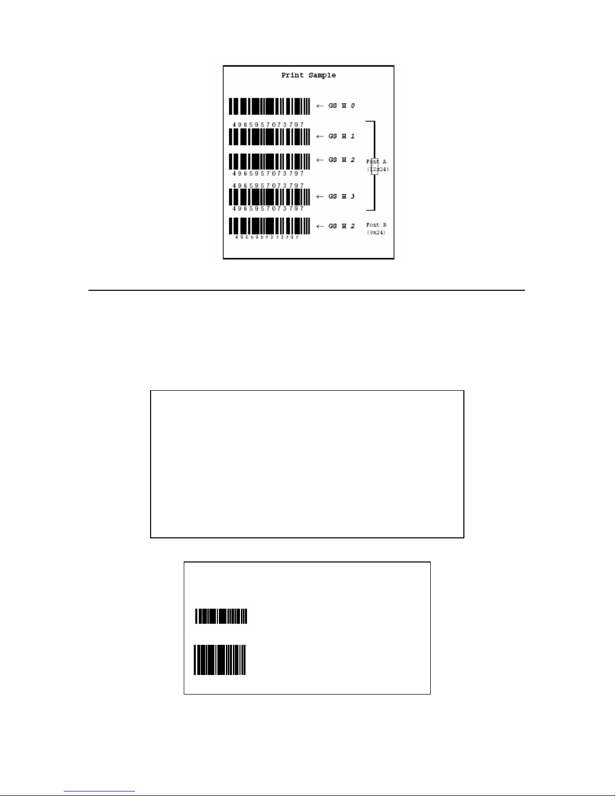
z GS H n Select printing position of HRI characters
Format: ASCII GS H n
Hex 1D 48 n
Decimal 29 72 n
Range: 0≤n≤3
48≤n≤51
GS H n selects the printing position for HRI characters when printing a bar code. n selects the printing
position as follows:
The default setting is n=0. HRI characters are printed at the position specified by GS H.
Page 71
68
z GS h n Set bar code height
Format: ASCII GS h n
Hex 1D 68 n
Decimal 29 104 n
Range: 1≤n≤255
GS h n selects the height of a bar code. n specifies the number of dots in the vertical direction. One dot
corresponds to 1/180 inch. The default setting is n=162.
Program Example
PRINT #1,CHR$(&H1D);"h";CHR$(50);Set height to 50
PRINT #1,CHR$(&H1D);"k";CHR$(2);Print bar code
PRINT #1,"496595707379";CHR$(0);
PRINT #1,CHR$(&HA);
PRINT #1,CHR$(&H1D);"h";CHR$(100);Set height to 100
PRINT #1,CHR$(&H1D);"k";CHR$(2);Print bar code
PRINT #1,"496595707379";CHR$(0);
PRINT #1,CHR$(&HA);
Print Sample
Height: 50 dots
Height: 100 dots
Page 72
69
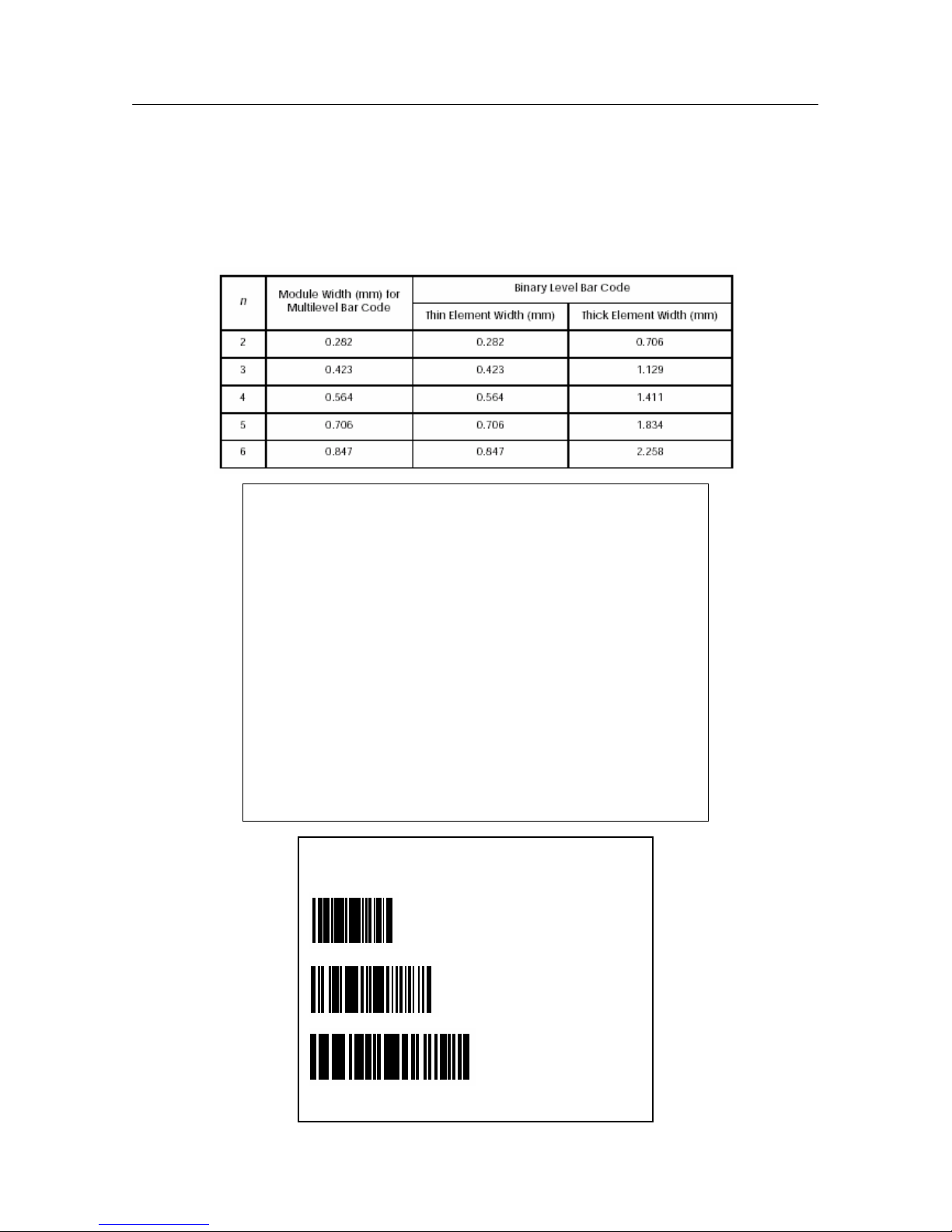
z GS w n Set bar code width
Format: ASCII GS w n
Hex 1D 77 n
Decimal 29 119 n
Range: 2≤n≤6
GS w n selects the horizontal size of a bar code. n specifies the bar code width as shown below. The
multilevel bar codes are UPC-A, UPC-E, JAN13 (EAN13), JAN8 (EAN8), CODE93, and CODE128. The
binary level bar codes are CODE39, ITF, and CODABAR. The default setting is n=3.
Program Example
PRINT #1,CHR$(&H1D);"w";CHR$(3);Set width size to 3
PRINT #1,CHR$(&H1D);"k";CHR$(2);Print bar code
PRINT #1,"496595707379";CHR$(0);
PRINT #1,CHR$(&HA);
PRINT #1,CHR$(&H1D);"w";CHR$(4);Set width size to 4
PRINT #1,CHR$(&H1D);"k";CHR$(2);Print bar code
PRINT #1,"496595707379";CHR$(0);
PRINT #1,CHR$(&HA);
PRINT #1,CHR$(&H1D);"w";CHR$(5);Set width size to 5
PRINT #1,CHR$(&H1D);"k";CHR$(2);Print bar code
PRINT #1,"496595707379";CHR$(0);
PRINT #1,CHR$(&HA);
Print Sample
Width size 3
Width size 4
Width size 5
Page 73
70
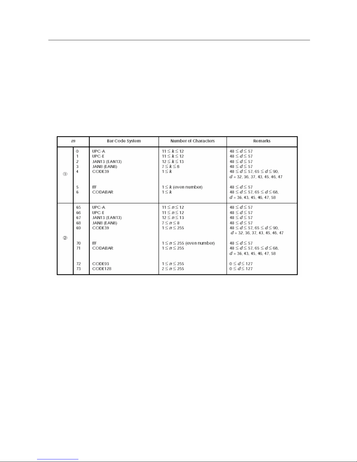
z GS k m d1 ... dk NUL GS k m n d1 ... dn Print bar code
Format: ①ASCII GS k m d1 ... dk NUL
Hex 1D 6B m d1 ... dk 00
Decimal 29 107 m d1 ... dk 0
②ASCII GS k m n d1 ... dn
Hex 1D 6B m n d1 ... dn
Decimal 29 107 m n d1 ... dn
Range: ①0≤m≤6 (k and d depend on the bar code system used)
②65≤m≤73 (n and d depend on the bar code system used)
①GS k m d1 ... dk NUL and ②GS k m n d1 ... dn select a bar code system and print the bar code. m specifies a
bar code system as follows:
Note: for ①
∗ This command is quit by the NULL code.
∗ For UPC-A and UPC-E, a bar code is printed when 12 bytes of bar code data are input. Subsequent data is
processed as normal data.
∗ For JAN13 (EAN13), a bar code is printed when 13 bytes of bar code data are input. Subsequent data is
processed as normal data.
∗ For JAN8 (EAN8), a bar code is printed when 8 bytes of bar code data are input. Subsequent data is processed
as normal data.
∗ The data count for ITF bar codes is always even numbered. If the data count is odd numbered, the last data is
ignored.
For ②:
∗ n specifies the data count. n bytes from the next data is processed as bar code data.
∗ If n is outside of the defined region, the command is stopped and normal printing commences from subsequent
data.
When in standard mode:
∗ If d is outside of the defined region, only a paper feed is executed and normal printing commences from
Page 74
71
subsequent data.
∗ If the horizontal width of the bar code exceeds the print region of one line, the paper is fed without printing the
bar code.
∗ Executes a paper feed for the height of the bar code (including HRI characters when HRI character printing is
specified) regardless of the line feed amount using the following commands.
a. ESC 2: Set default line spacing
b. ESC 3: Set line feed amount
∗ This command is effective only when no data exists in the print buffer. If there is data in the print buffer, data
after m is printed as normal data. Sets the next print position to the beginning of the next line after printing the
bar code.
∗ Excluding upside-down printing, print modes (emphasized printing, double printing, underlines character sizes)
are unaffected.
When in page mode:
∗ Executes only a bar code expansion but does not print it. After expanding the bar code, the next dot after the
last data of the bar code is the starting position for the expansion of subsequent data.
∗ If d is outside of the defined region, the command is stopped and normal printing commences from subsequent
data. The position for starting data expansion does not move.
∗ If the horizontal width of the bar code exceeds the print region of one line, the data expansion starting position
is moved to the left side outside the printing region without printing the bar code.
Reference: GS H, GS f, GS h, GS w
z ESC t n Select character code table
Format: ASCII ESC t n
Hex 1B 74 n
Decimal 27 116 n
Range: 0≤n≤5
n = 255
ESC t n selects a page n from the character code table as follows. The default setting is page 0 (n=0).
The alphanumeric characters (20H (decimal 32) to 7FH (decimal 127)) are the same for each page. The
extended characters (80H (decimal 128) to FFH (decimal 255)) are different for each page.
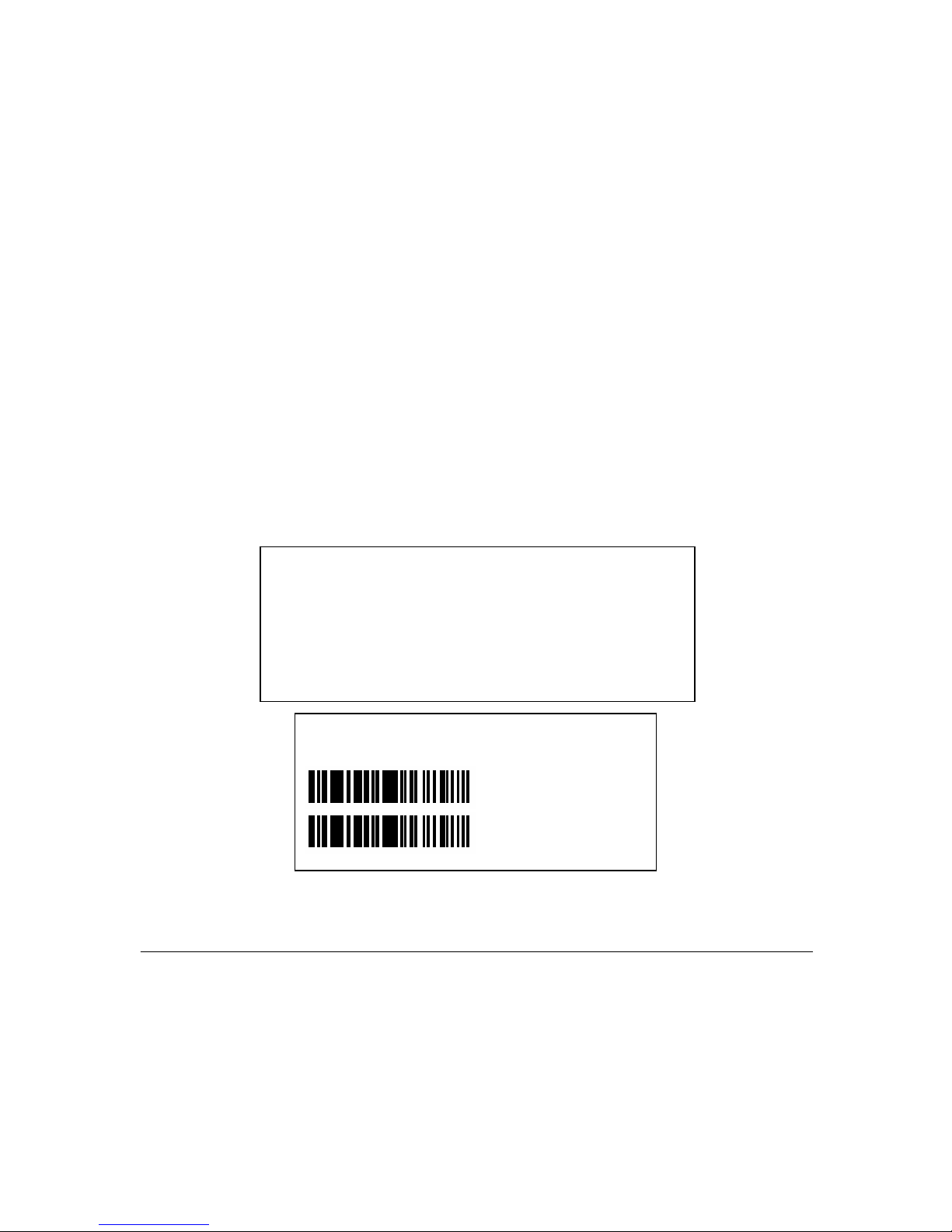
Program Example
PRINT #1,CHR$(&H1D);"k";CHR$(2);Print bar code
PRINT #1,"496595707379";CHR$(0);
PRINT #1, CHR$(&HA);
PRINT #1, CHR$(&H1D); "k";CHR$(67); CHR$(12);
PRINT #1,"496595707379"; Print bar code
Print Sample
Page 75

72
15 COMMAND SAMPLE (hex command)
1d 68 64 1d 6b 02 34 39 36 35 39 35 37 30 37 33 37 39 00 0a
//print a barcode width 1, height 100
1d 77 02 1d 6b 02 34 39 36 35 39 35 37 30 37 33 37 39 00 0a
// print a barcode width 2, height 100
1d 77 02 1d 6b 02 32 32 30 30 30 30 32 30 30 30 35 30 35 00 0a
// print EAN-13 barcode
1d 6b 00 30 30 30 30 30 30 30 30 30 30 30 00 0a
//print UPC-A barcode
1d 6b 03 30 30 30 30 30 30 30 30 00 0a
//print EAN-8 barcode
1d 6b 04 30 30 30 30 30 30 30 30 30 30 30 30 30 00 0a
// CODE39
1d 68 64 1d 48 03 1d 6b 04 30 30 30 30 30 30 30 30 30 30 30 30 30 00 0a
//set the position of digits on the barcode
Page 76

DPP701ENV0-12
 Loading...