

Page 1

OS2X CHECKOUT SCALE
USER MANUAL
Pinnacle Technology Corp.
Page 2

Page 3

CONTENTS
1. SUMMARIZATION ............................................................................................................................... 1
1.1 ADVANCED FUNCTIONS ........................................................................................................ 1
1.2 EXCELLENT FUNCTIONS ....................................................................................................... 1
2. TECHNICAL SPECIFICATION ............................................................................................................ 2
3. APPEARANCE ...................................................................................................................................... 3
4. DIMENSION .......................................................................................................................................... 5
5. HOW TO FIX CUSTOMER DISPLAY TO CHECKOUT SCALE....................................................... 7
6. HOW TO INSTALL DISPLAY POLE ................................................................................................... 8
7. POWER CONNECTIONS ..................................................................................................................... 9
8. POWER ON/OFF ................................................................................................................................. 11
9. KEY EXPLANATION ......................................................................................................................... 11
10. WARNING ........................................................................................................................................ 12
11. SOFTWARE OPERATION .............................................................................................................. 12
12. USB VIRTUAL SERIAL PORT DRIVER INSTALLATION .......................................................... 13
13. COMMUNICATION PROTOCOL .................................................................................................. 15
Page 4

1
1. SUMMARIZATION
1.1 ADVANCED FUNCTIONS
※ Communication platter which adopts patent insect-proof design can prevent the machine from
defects caused by insects.
※ Can be used as stand-alone, or connect with POS/ECR.
※ Imbedded design to save valuable counter space.
※ Optional wireless type,able to transmit weighting data to POS/ECR in time without lines.
※ Patent tempered glass platter, practical and good looking.
1.2 EXCELLENT FUNCTIONS
※ Two options of customer display: external or in-built, able to meet customers‟ need in all-round.
※ Tare, zero and other function keys on the display, easy to operate and convenient to check out the
weighting information.
※ Simple elegant design and compact internal process guarantee products‟ reliability and aesthetics.
※ Standard protocol, convenient to connect with POS/ECR.
※ Two optional measuring range: 15kg(e=2g/5g)or 30kg(e=5g/10g).
电
源
开
关
Page 5

2
2. TECHNICAL SPECIFICATION
Specification of types
Desktop Type OS2CX
Imbedded Type OS2IX
OS2CX
OS2CXK
OS2CXB
OS2CXP
OS2IX
OS2IXD
Basic Features
without display
without keys
without display;
with two keys
with pedestal display
& three keys
with display, pole
& three keys
without display;
with two keys
With separate pole;
display & three keys
Dimension
344.93*262.54
*87.8mm
344.93*262.54
*87.8mm
344.93*343.2
*91.04mm
435.22*344.93
*337.87mm
370*288
*72.4mm
Platter
370*288*
72.4mm
Display pole
415.72*111.57
*86.35mm
Customer/Operator Display
5*8 field LCD
Weighing Capacity (Max.)
6/15kg;15/30kg
Division Value
2/5g;5/10g
Weighing Capacity (Min.)
40g;100g
Tare (Max.)
-5.998kg;-14.995kg
Internal Resolution
1/30000
Accuracy Class
Interface
RS232
Optional
USB、2.4G wifi communication
Power Supply
5V 1A
Working Temperature
0℃-40℃
Working Humidity
5%R.H.-85%R.H.
Page 6

3
3. APPEARANCE
OS2CX
OS2CXK
OS2CXB
OS2IX
OS2CX is the type without display screen
& keys.
Without display screen, but with two key
(tare key and zero key)
Display screen is on the pedestal, with
three keys.
Embedded type, without display screen,
but with two keys.
Page 7

4
OS2CXP
OS2IXD
With display screen and three keys.
With separate display screen, three key.
Display screen‟s position can be installed
according to actual needs.
Page 8

5
4. DIMENSION
outline dimensional drawing
OS2CX/OS2CXK
OS2CXB
OS2CXP
OS2IX
Page 9

6
Installing hole dimension figure of OS2IX type
OS2IXD
OS2IXD-platter
OS2IXD-display pole
Page 10

7
5. HOW TO FIX CUSTOMER DISPLAY TO CHECKOUT SCALE
Please follow below steps to install the customer display, if the type you bought with it.
Insert the line to the port
Lock the screws
Page 11

8
6. HOW TO INSTALL DISPLAY POLE
Please follow below steps to install the display pole, if the type you bought with it.
Lock the screws to
fix the display pole
on the pedestal
Lock the screws to
fix the display pole
on the bottom of
the platform.
Fix the pole
like the
picture shows.
Page 12

9
7. POWER CONNECTIONS
There are 3 methods for OS2X to get power supply.
Method 1: Use the attached communication line to connect Aclas ECR as below picture.
Customer can self-define the length of communication line, if the line is too long,
customer can cut one end of crystal head short and follow the connection mode below to
make a new one.
PHONE4
Pin
Signal name
1
VDD
2
GND
3
TXD
4
RXD
PHONE4
Pin
Signal name
1
VDD
2
GND
3
RXD
4
TXD
Connect to
OS2X
Connect to Aclas ECR
or LP1X label printer
RS232 line
Able to self-define the length
Connection mode
Page 13

10
Method 2:If the external device or PC is attached with D9 interface, customer can use a
D9-4P communication cable with USB interface from Aclas to get power supply.
Connect the OS2X with the external device as below picture. If supply power is
available from the D9 interface of external device, there is no need to connect with other
power supply.
Method 3: If you purchased USB line, you can follow below picture to connect OS2X
and other terminal with USB port.
Note: To set the communication between the OS2X and the external device that has USB
interface, users should install USB virtual serial port driver first. Please refer to related
chapter for details.
Connect to USB
port of PC or
other terminal
Connect to
OS2X
Connect to D9
port of PC or
other terminal
Communication line, connect to
OS2 (Able to self-define the length)
Power plug
If the line is too short, use
USB cable to prolong it
Connect PC or
power supply
Page 14
11
8. POWER ON/OFF
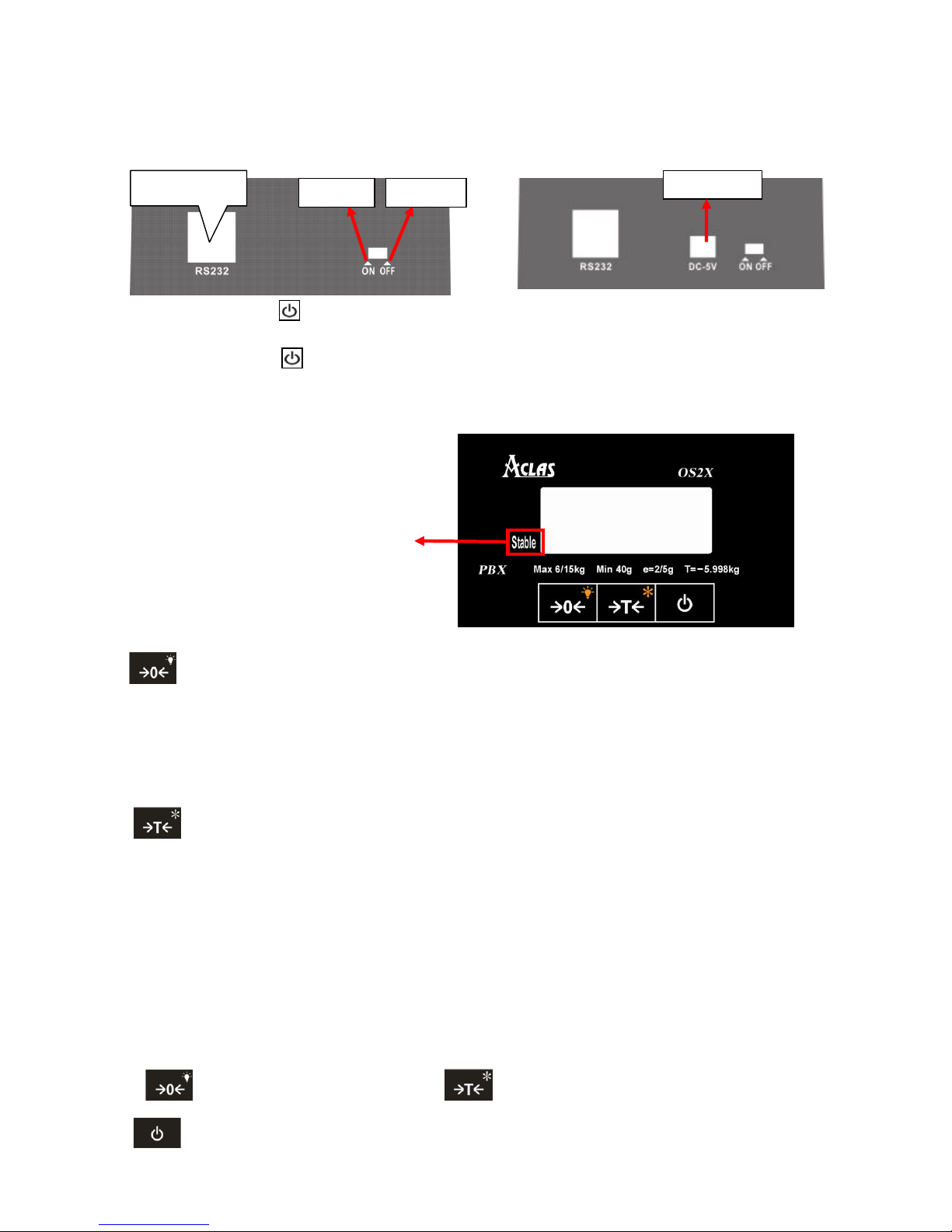
Power on: press the key to power on after soft turning off.
Power off: press the key to power off.
9. KEY EXPLANATION
: This key is to adjust the „WEIGHT‟ column to zero value.
Place the scale level steadily, if there are digits displayed on LCD when there is nothing on the
platter, you can press this key to adjust to zero.
Press this key and hold it for 1.5 seconds to turn on or turn off the backlight.
: This key is used to deduct the packing weight.
If you need to deduct the packing weight, put the container or wrapper on the scale first, and
then press this key to enter weight- deducting state. Then, take off the container and put the
commodity into the container and then place the packed goods on the pan again, now, the LCD will
display the net weight. Remove the merchandise and press this key, the scale will return to normal
weighting state.
Press this key and hold it for 1.5 seconds to enter into the unit switch function. Press the key
“ ”to shift the unit and press the key “ ” to confirm or exit the setting status.
: Press this key and hold it for 1.5 seconds to soft turn off the scale.
There is “stable” mark on the display
screen. When the weight is stable, the
triangle indicator will light which means it
is in the normal weighing status, at this
time you can put commodity on the platter
RS232 port
Power on
Power off
English version
For Mexico
Power port
Page 15

12
10. WARNING
Avoid overloading.
Do not operate the printer in a humid environment.
Do not operate the scale under the place of flammability and explosive.
11. SOFTWARE OPERATION
Double click , and then below interface will pop up:
1 Select the corresponding
serial interface,baud rate9600
2Click this
button
Information
Weight display
Page 16

13
12. USB VIRTUAL SERIAL PORT DRIVER INSTALLATION
If you purchased optional accessory USB line, you must install USB virtual serial
driver to realize the communication between OS2X and external equipments. If you
purchased D9 line, you can skip this chapter.
Open disk and run software“VCPDriver_V1.1_Setup.exe”:
Click“Next”
Page 17

14
Click“Next”
Click“Finish”
Page 18

15
13. COMMUNICATION PROTOCOL
Send communication protocol actively :
Default send 10 times/s when power on. Frequency can be adjusted and the adjusting method is
same with OP box.
sending content is as follows:
Head1
Head2
Flag1
Sign
Weight
Unit
CheckSum
Tail1
Tail2
Flag2 0 1 2 3
4~9
10,11
12
13
14
15
Head1:1 byte,fixed as 0x01.
Head2:1 byte,fixed as0x02.
Flag1:1 byte,status: F’: Weight is beyond the range or haven‟t startup to zero.
‘S’: Weight is stable.
‘U’: Weight is unstable.
Sign:1 byte,sign: ‘-’:Weight is negative.
‘ ’: Weight is positive.
Weight:6 bytes,weight
Unit:2 bytes,unit
CheckSum: 12 bytes in front of the vision exclusive or and.
Tail1:1 byte,fixed as 0x03.
Tail2:1 byte,fixed as 0x04.
Flag2:1 byte,status:
Bit4:1: The current weight is zero. 0:The current weight is not zero.
Bit5:1: current in the tare mode 0: Not in tare mode.
Bit6:1: Weight is beyond the range or haven‟t startup to zero. 0: Weight is in normal and has
startup to zero.
Send communication protocol passively
1>PC Request the connection firstly
PC Send one byte command 0x05 firstly.
command
0x05
Scale response one byte command 0x06.
PC can confirm the scale has connected via these two commands firstly.
comman
d
0x06
2>PC Request to receive the weighing result.
PC sends one byte command 0x11.
command
0x11
scale response weighing result,response data format and the format of sending actively is basically the
same, just miss Flag2.
Page 19

16
Head1
Head2
Flag1
Sign
Weight
Unit
CheckSum
Tail1
Tail2 0 1 2 3
4~9
10,11
12
13
14
Head1:1 byte,fixed as 0x01.
Head2:1 byte, fixed as 0x02.
Flag1:1 byte,status: ‘F’: Weight is beyond the range or haven‟t startup to zero.
‘S’: Weight is stable.
‘U’: Weight is unstable.
Sign:1 byte,sign: ‘-’:Weight is negative.
‘ ’: Weight is positive.
Weight:6 bytes,weight
Unit:2 bytes,unit
CheckSum:12 bytes in front of the vision exclusive or and.
Tail1:1 byte,fixed as 0x03.
Tail2:1 byte,fixed as 0x04.
tare zero by active or passive way
1. Tare or zero
PC sends
STX
Cmd
ETX1
ETX2
0
1,2
3
4
STX:1 byte,fixed as 0x3C.
Cmd:2 bytes, tare fixed as 0x54, 0x4B.
zero fixed as 0x5A ,0x4B.
ETX1:1 byte,fixed as 0x3E.
ETX2:1 byte,fixed as 0x09.
Pinnacle scale DigitOpBox protocol
1)Communication package format:
1.Communication package format:
A:without data column‟s format(not including DATA and DT SUM)
STX
ID
CMD
PARA
PGNO
LEN
SUM
0
1,2,3,4
5,6
7,8 9 10,11
12
SUM = Byte0 + Byte1 + Byte2 + … + Byte10 + Byte11
B:with data column‟s format(LEN > 0)
STX
ID
CMD
PARA
PGNO
LEN
SUM
DATA
DT SUM
0
1,2,3,4
5,6
7,8 9 10,11
12
13 ~ (13+LEN-1)
(13+LEN ),
(14+LEN)
SUM = Byte0 + Byte1 + Byte2 + … + Byte10 + Byte11
DT SUM = CRC16 ( Byte13 ~ Byte[13+LEN-1] )
Note:
1.When LEN is 0, DATA column and DT SUM are empty, at this time, data Packet total
length is 13 bytes.
Page 20

17
2.When LRN is not 0, DT SUM‟s CRC checksum is only related with DATA column, and
is not related to the prior 13 bytes, at this time, data package total length is (13+LEN+2)
byte.
3.High order is in front and the low order is in rear to multi-byte column.
2. Communication package format explanation:
3. .communication command:
CMD1
CMD2
PARA1
PARA2
EXPLANATION
0x80
0x00
Baud Rate
0x00
Set communication baud rate
0x80
0x01
Frq
0x00
set measuring result sending frequency
0x80
0x02
0x00
0x00
read measuring result
0x80
0x03
0x00
0x00
start zero device
0x80
0x04
0x00
0x00
start tare device
0x80
0x05
Tare
start or stop preset tare device
0x80
0x06
Unit
0x00
set measuring unit
0x80
0x0d
0x00
0x00
The response of OP box(Command failure)
0x80
0x0e
0x00
0x00
The response of OP box(Command success )
2)Command explanation:
4. Set communication baud rate:( Successful response 0x800E,Failure response 0x800D)
STX
ID
CMD
PARA
PGNO
LEN
SUM
0xAB
0x00000000
0x8000
0xXX00
0
0x00
X
Default the baud rate is 9600bps when power on. When the command is received successfully, change
baud rate by parameter PARA1.
XX = 0x01 : 115200 bps
XX = 0x02 : 57600 bps
XX = 0x03 : 38400 bps
XX = 0x06 : 19200 bps
XX = 0x0C : 9600 bps
Command use method:PC use the default baud rate 9600bps to send this command to OP box firstly, and
then continue to use 9600bps baud rate to response after OP box received the command. Then switch the
S/N
items
explanation
length(bytes)
mark
1
STX
Package head
1
Communications packet starting marks 0xAB
2
ID
Scale number
4
keep,fill all with 0
3
CMD
command 2 Command classification
4
PARA
parameter
2
Parameter related with command
5
PGNO
Package
number
1
Data package number(single/last one fill with0)
6
LEN
length
2
data length
7
SUM
checksum
1
The sum form item1to item6, total 12 bytes
8
DATA
data
LEN
Command data,Max 49 bytes
9
DT
SUM
Data
checksum
2
CRC checksum of 8
Page 21

18
baud rate to the corresponding baud rate again after response data sending finished.
5. set measuring result sending frequency:( Successful response 0x800E,Failure response 0x800D)
STX
ID
CMD
PARA
PGNO
LEN
SUM
0xAB
0x00000000
0x8001
0xXX00
0
0x00
X
Default frequency is sending 10 times measuring result in each second actively. When the
command is received successfully, change the frequency according to parameter PARA1.
XX = 0x0A : 10Hz
XX = 0x09 : 9Hz
XX = 0x08 : 8Hz
………
XX = 0x01 : 1Hz
XX = 0x00 : send measuring result passively, at this time you can achieve the measuring
result via the command “read measuring result”.
6.Read measurement results:
STX
ID
CMD
PARA
PGNO
LEN
SUM
0xAB
0x00000000
0x8002
0x0000
0
0x00
X
When initiative sending frequency is set as 0, achieve the measurement results: via this
command.
Please refer to note 1 about the returned data analysis.
7.Zero command:( successful response 0x800E,failure response 0x800D)
STX
ID
CMD
PARA
PGNO
LEN
SUM
0xAB
0x00000000
0x8003
0x0000
0
0x00
X
Sensor starts zero device after sending this command.
8.Tare command:( successful response 0x800E,failure response 0x800D)
STX
ID
CMD
PARA
PGNO
LEN
SUM
0xAB
0x00000000
0x8004
0x0000
0
0x00
X
Sensor starts tare device after sending this command.
9.Start or stop preset tare device:( successful response 0x800E,failure response 0x800D)
STX
ID
CMD
PARA
PGNO
LEN
SUM
0xAB
0x00000000
0x8005
Tare 0 0x00
X
Sensor starts or stop preset tare device after sending this command.
The range of tare is 0~ the maximum tare value allowed.
When tare is 0, it will stop preset tare device. When tare is not 0, it will start preset tare
device.
10. Change measuring unit:( successful response 0x800E,failure response 0x800D)
STX
ID
CMD
PARA
PGNO
LEN
SUM
0xAB
0x00000000
0x8006
0xXX00
0
0x00
X
The default unit is kg when power on, when command is received successfully, change
the unit according to the parameter PARA1.
XX = 0:standard unit(kg)
Page 22

19
XX = 1: standard unit(g)
XX=6:British unit(pound)
XX=7:British unit(ounce)
Note 1:
The sensor returned the measured results of data format:
1.Data
STX
ID
CMD
PARA
PGNO
LEN
SUM
0xAB
0x00000000
0x8002
0x8300
0xXXXX
0
0x00
X
When adopting 0x8002 command achieve measurement results, answering CMD is
0x8002.
When sensor is set for the certain frequency and sent measurement results automatically,
CMD is 0x8300.
PARA:the current temperature AD.
2.Data in data area
Flag
Mode
Unit
Decimal Digit
Net Value
Tare Value
Gross Value
0 1 2 3 4,5,6,7
8,9,10,11
12,13,14,15
Flag: Bit0: 0 means weight is unstable 1 means weight is stable
Bit1: 0 means weight is in its range. 1 means weight is beyond the range.
Bit2: 0 means have startup to zero. 1 mean haven‟t startup to zero.
Bit3: 0means the current weight is more than the minimum weighing range
1 means the current weight is less than the minimum weighing range
Bit4: 1 the current OP box is soft unlock 0 the current OP box is not soft unlock
Bit5: 1 the current OP box hardware is unlock 0 the current OP box hardware is not
unlock
Bit6: 1 the lowest order of the result is always zero. 0 the lowest order of the result maybe
not zero.
Bit7: retain
Mode: 0:It stands for net weight weighing mode, at this time, tare and gross weight
column not transmission.
1:It stands for tare weighing mode.
2:It stands for Pre-set tare weighing mode.
Unit:
0: "Gram",
1: "kg",
2: "Tonne",
13: "Ounce",
14: "Pound",
15: "Kilo pound (kip)",
Decimal digits
Each weight value occupies 4 bytes, high-order in the front, and low in the rear. The highest Bit is the
sign bit. For example:
Flag
Mode
Unit
Decimal Digit
Net Value
0x01
0x00
0x01
0x03
0x80,0x00,0x04,0xD2
Page 23

20
When receive the above data, it means: weight is stable, net weight weighing model, unit
kg, 3 decimal places, symbol is negative, -1.234 kg.
Flag
Mode
Unit
Decimal Digit
Net Value
0x00
0x00
0x00
0x00
0x00,0x00,0x04,0xD2
When receive the above data, it means: weight is unstable, net weight weighing model, unit
g, 0 decimal places, symbol is positive, 1234 g.
5) Protocol change
1. PC sends replacement protocol
STX
Cmd
ETX1
ETX2 0 1,2
3
4
STX:1 byte,fixed as 0x3C.
Cmd:2 bytes, OS2passively sends communication protocol fixed as 0x41, 0x4C.
OS2 actively sends communication protocol fixed as 0x50, 0x42.
Pinnacle scale DigitOpBox protocol fixed as 0x44, 0x42.
ETX1:1 byte,fixed as 0x3E.
ETX2:1 byte,fixed as 0x09.
Page 24

DOS201ENV0-OS2X-09
 Loading...