

Page 1

Safety Mat System
Installation
and
Operation Manual
Page 2

Rev. 2.3
Page 3

NSD Safety Mat System
Installation and Operation Manual
Pinnacle Systems, Inc.
3715 Swenson Avenue
St. Charles, IL 60174
P/N: 28-045r2.3
(Please have Model #, Serial #, and Software Rev # Available)
www.pinnaclesystems.com • sales@pinnaclesystems.com • service@pinnaclesystems.com
Customer Service: 630-443-8542 (CST)
Sales and Marketing: 800-569-7697 (EST)
Page 4

Proper Use and Limitations
The NSD Safety Mat System is critical for operator
safety. Repairs should only be made by factory
authorized personnel. The manufacturer cannot be
held responsible for your repair attempts or the unit’s
subsequent safe operation.
As the NSD Safety Mat System is a single function
device, that of sensing an unauthorized intrusion into
a guarded area while simultaneously determining that
it is capable of sensing such an intrusion, any internal
malfunction will manifest itself with a RED condition
shut down. The manufacturer will not supply individual
component parts of any circuit board but will supply the
individual circuit board complete.
The information disclosed herein includes proprietary
rights of the manufacturer. Neither this document nor
the information disclosed herein shall be reproduced
or transferred to other documents, used or disclosed
to others for manufacturing purposes, or for any other
purposes, except as specifi cally authorized in writing
by the manufacturer. If this manual is supplied in
connection with the sale or delivery of manufacturer’s
equipment, it is to be used solely for maintenance, repair
or installation of such equipment.
Limitation of Liability
In the event of any claim for breach of any obligations
of manufacturer under any order, whether expressed
or implied, and particularly in the event of any claim
of a breach of the warranty or warranties contained in
the paragraph “Warranty” or of any other warranties,
expressed or implied which might, despite the paragraph
entitled “Disclaimer,” be determined to be incorporated
in any order, the company shall under no circumstances
be liable for any consequential or special damages,
either in law or in equity, or for losses or expenses or
claims for the same arising from the use of, or inability
to use, the products of the manufacturer for any purpose
whatsoever.
The manufacturer has designed this equipment to
the very highest performance and safety standards
known to the current technological state of the art.
However, the installation, usage, suitability, and fi tness
of our equipment for any purpose, known or unknown,
is interdependent upon the performance of other
equipment not manufactured, installed, secured or
maintained by the manufacturer. W e cannot and do not
accept responsibility for any overall system performance
when factors, such as these, are beyond our control.
Warnings and Warranty
Manufacturer warrants that this product will be free
from defects in material and workmanship for a period
of two years from the date of shipment thereof. Within
the warranty period, manufacturer will repair or replace
such products which are returned with shipping charges
prepaid and which will be disclosed as defective upon
examination by the manufacturer. This warranty will not
apply to any product which will have been subject to
misuse, negligence, accident, restriction, and use not
in accordance with manufacturer’s instructions or which
will have been altered or repaired by person’s other than
the authorized agent or employees of the manufacturer.
Disclaimer
The provisions of the “Warranty” paragraph above are
the sole obligations of the manufacturer and exclude
all other warranties of merchantability, expressed or
implied. Further, there are no warranties which extend
beyond the above warranty.
WARNING: The entire machine safety system
must be tested at the start of every shift. Machine
testing should include: (1) proper machine
operation and stopping capability; and (2)
verifi cation of proper installation and settings of
all point of operation guards and devices before
the operation is released for production.
Page 5

Table of Contents
Overview
Circuit Description ...................................................................................................................................................1
Specifi cations .......................................................................................................................................................... 2
Dimensions
1. NSD-TR-01 (Metal Box) Controller ..............................................................................................................3
2. NSD-DR-01 (Basic DIN-rail) and NSD-DR-04 (DIN-rail with diagnostics) Controllers ...............................3
Installation and Operation
Mat Installation ........................................................................................................................................................4
Controller Installations
NSD-TR-01 (Metal Box) Controller ...................................................................................................................4
NSD-DR-01 (Basic DIN-rail) Controller ...........................................................................................................5
NSD-DR-04 (DIN-rail with diagnostics) Controller ............................................................................................5
Operation
1. Stop Circuit (application) .............................................................................................................................6
2. Manual/Automatic Reset .............................................................................................................................6
3. External Relay Checking .............................................................................................................................6
Wiring Diagrams
1. NSD-TR-01 (Metal Box) Controller ..............................................................................................................7
1. NSD-TR-01 (Metal Box) Controller - Older boards PRIOR to Rev 10 .........................................................8
2. NSD-DR-01 (Basic DIN-rail) Controller .......................................................................................................9
3. NSD-DR-04 (DIN-rail with diagnostics) Controller .....................................................................................10
NSD-DR-04 (DIN-rail with Diagnostics) Accessible Connections .........................................................................11
NSD-DR-04 (DIN-rail with Diagnostics) Board Connector Layout ........................................................................12
Appendix A: Troubleshooting
NSD-TR-01 (Metal Box) and NSD-DR-01 (Basic DIN-rail) Controllers .............................................................AA-1
NSD-DR-04 (DIN-rail Controller with diagnostics) ............................................................................................AA-1
DeviceNet (for NSD-DR-04 only) ......................................................................................................................AA-3
Appendix B: Saftey Guidelines for Management
Operational Safety ............................................................................................................................................AB-1
Safety Enforcement ..........................................................................................................................................AB-2
Supervisor Training ...........................................................................................................................................AB-2
Operator Training ..............................................................................................................................................AB-2
- I -
Page 6

Overview
NSD Safety Mat System
Overview
The NSD Safety Mat System contains two independent
control circuits which allow for shut down due to any
single failure in one of the control circuits. The N.O.
output circuit is controlled by two captivated contact
relays in series which are both monitored. If the contact
in one relay should stick closed (i.e., contact weld) the
other relay will shut down and an LED will indicate the
fault, even if the contact on the bad relay opens back up
you must reset the power to clear the fault. The relay
contact monitoring provides a high degree of user safety .
Circuit Description
The NSD-TR-01 (metal box) and NSD-DR-01 (basic
DIN-rail) are alike in that they use discrete logic circuits
to detect the mat. The NSD-DR-04 (DIN-rail with
diagnostics) is diverse redundant microprocessor driven
and has a built-in diagnostics display. A low voltage
(24VAC) signal is sent out to the safety mat(s) through
two wires. The voltage passes through the mat and back
into the NSD control unit through two more wires. Two
special optically-isolated diverse redundant circuits look
at the signals coming back from the mat(s) detecting the
presence of proper positive and negative voltage (AC)
levels and output their signals to redundant missing
pulse detectors. If the voltage coming back is too high
or low, the missing pulse detectors will drop out and
de-energize the relay circuit. If the voltage coming back
is not AC (missing either positive or negative peaks),
then the signal going to the missing pulse detector will
disappear which will, in turn, drop out and de-energize
the relay circuit.
3. If any wire going to or coming from the mat(s)
is cut and/or shorted to any other mat wire, the
signal going back into the NSD control unit is
OV, so the relays de-energize.
4. If any wire going to or coming from the mat(s)
is cut and/or shorted to an outside AC power
source (i.e., 120VAC) the signal going back
into the NSD control unit will exceed the 24V AC
signal level and the relays will de-energize.
5. If any wire going to or coming from the mat(s)
is cut and/or shorted to an outside DC power
source (i.e., 24VDC), the signal going back into
the NSD control unit will not be an AC signal
and the relays will de-energize.
6. If, when you step on the mat, either safety output
relay is stuck in the closed position, the NSD
control unit will automatically shut down the
other relay and lock out and further attempts
to reset the unit until the power is reset.
Redundant relay position detectors watch for a relay
contact stuck in the wrong position. The circuits will lock
out the reset feature of the NSD control unit if a relay
contact is closed when it should be open.
Each relay has its own driver circuit to complete the
redundancy of the circuits.
The output relays will de-energize if the voltage coming
from the mat(s) is either too high or low (12VAC to
36VAC) or is not AC (i.e., DC), including the following
reasons:
1. When you step on the mat, you are shorting
out the 24VAC signal going back into the NSD
control unit to OV, so the relays de-energize.
2. If you cut any wire going to or coming from
the mat(s), the signal going back into the NSD
control unit is OV, so the relays de-energize.
1
6
Page 7

Specifi cations
NSD Safety Mat System
Enclosure:
Input Power:
Category/Type:
Relay Style:
Relay Configuration:
Safety Relay Rating:
Reset Provisions:
Controller Response
Time:
Self-Checking
Intervals:
Number of Isolated
Zones:
Maximum Number of
Mats:
External Reset
Provision:
Indicators:
Internal (on board):
External:
NSD-TR-01
Controller
(Metal Box)
NEMA 12, 13, IP 54 NEMA 1, IP 32 NEMA 1, IP 32
120VAC +/- 10% @ 3 watts
50-60 Hz fused
4 4 4
Monitored force-guided captive
contact safety relays
2 N.O. Safety Relays (closed
when circuit activated)
1 Aux Output N.O. or N.C
4A @ 220VAC 4A @ 220VAC 4A @ 220VAC
Manual or Automatic Manual or Automatic Manual or Automatic
15 msec. 15 msec. 19 msec per mat input used
Every 20 msec. Every 20 msec. Every 20 msec.
1 to 13 (customer specified) 1 per controller 1 per controller
20 20 4 with homerun wiring
Green push button Green push button Green push button
Yellow LED
supply
Red LED = Normally dim,
brighter when mat is stepped
on. Cut wire detected when
not lit.
Green LED = Relay contact
detected closed when it should
have been open when not lit.
Must reset power to clear.
Red LED
de-energized.
Green LED = All relays are
energized.
= +5VDC power
= 1 or both relays are
24VDC +/- 20% @ 7 watts 24VDC +/- 20% @ 7 watts
Monitored force-guided captive
contact safety relays
2 N.O. Safety Relays (closed
when circuit activated)
1 Aux Output N.O. or N.C
Green LED(s) = next to
each relay (3)
Red LED
Yellow LED = +5V
Green LED
Red LED = 1 or both relays are
de-energized.
Green LED = All relays are
energized.
Yellow LEDs = 2 to show on/off
mat.
Yellow LED = relay fault if it
turns off.
NSD-DR-01
Controller
(Basic DIN-rail)
= +12V
= -5V
NSD-DR-04
Controller
(DIN-rail with Diagnostics)
Monitored force-guided captive
contact safety relays
2 N.O. Safety Relays (closed
when circuit activated)
1 Aux Output N.O. or N.C.
1 Fault Relay N.O.
20 with daisy chain wiring
Red LED = +12VDC
Green LED
Yellow LED
Green LEDs
relay (4 total)
Red LED = 1 or both relays are
de-energized.
Green LED = All relays are
energized.
Yellow LEDs = 1 for each mat
status — (4 total)
= +20VDC
= +5VDC
= one for each
Diagnostic Message
Display:
DeviceNet:
Warranty:
N/A N/A Built-in
N/A N/A Add suffix DN to Model #. See
2 years 2 years 2 years
next page for additional
information.
2
3
Page 8

Specifi cations
NSD Safety Mat System
Dimensions
NSD-TR-01 (Metal Box Controller)
Board (NSD-TR-B1): 5” x 7” plate with 4 holes 4-1/4” x 6-1/4” on center.
127mm x 177.8mm with 4 holes 107.95mm x 158.75mm on
center
Box (NSD-TR-01): 8”h x 6”w x 3.5”d (4” x 8-3/4” holes), NEMA 12, 13
203.mm x 152.4mm x 88.9mm (101.6mm x 222.25mm holes)
(NSD-TR-02): 12”h x 10”w x 5”d (8” x 12-3/4” holes), NEMA 12, 13
304.8mm x 254mm x 127mm (203.2mm x 323.85mm holes)
(NSD-TR-03/04): 16”h x 14”w x 6”d (13” x 16-3/4” holes), NEMA 12, 13
406.4mm x 355.6mm x 152.4mm (330.2mm x 425.45mm holes)
(NSD-TR-05/up): Call for sizes available.
NSD-DR-01 and NSD-DR-04 (both DIN-rail Controller models)
Mounting: 35mm DIN-rail mountable or mounting screws on corners of enclosure requiring
3
4
Page 9

Installation and Operation
NSD Safety Mat System
WARNING: The entire machine safety system
must be tested at the start of every shift. Machine
testing should include: (1) proper machine
operation and stopping capability; and (2)
verifi cation of proper installation and settings of
all point of operation guards and devices before
the operation is released for production.
Mat Installation
The NSD mat system has been designed to promote
individual mat “homerun” wiring back to the mat
controller. This is suggested for easing installation
and diagnostics for maintenance troubleshooting. This
will also eliminate cumbersome “daisy chain” wiring
practices of mat systems. It also eliminates numerous
wiring connection points buried under the perimeter trim
which are time intensive to troubleshoot.
1) Sweep the fl oor area where the safety mat is to
be installed. The fl oor should be fl at and free
of foreign material.
2) Locate the safety mat in the desired location.
For future reference, install the mat with the
label side up.
3) Slide the black wire raceway component under
the mat edge (Part #M002). Refer to Figure 1
below for proper component positioning.
NOTE: The wire raceway component must be
installed whenever the surface perimeter trim
component is used.
4) Route the wire/plug assembly on the raceway
toward the mat controller location.
5) Lay the aluminum perimeter trim piece around
the mat assembly. Determine where the mat
wiring will exit the trim and notch the trim and
wire raceway for the wire to exit the assembly.
6) If surface metal raceway is used to route the
wiring (Part #M005 or M006) from the mat
assembly across the floor toward the mat
controller, it should be aligned with the notch
in the perimeter trim and anchored to the fl oor.
Route wires accordingly and snap cover plate
over the wires.
7) Slide the perimeter trim over the wire raceway
component and align over the mat edge. Drill
the perimeter trim and fl oor for securing the
perimeter trim to the fl oor with anchoring screws
and fl oor anchors.
8) If a multiple mat assembly is to be installed, use
the aluminum active coupler component (Part
#M003) to connect mats end to end or side to
side. Refer to Figure 1 below.
Controller Installation
NSD-TR-01 (Metal Box) Controller
IMPORTANT: The NSD-TR-01 Controller
provides both N.O. and N.C. output circuits, but
only Terminals 5-6 (N.O.) are safety monitored
and should be used in series with your stop
circuit. Terminals 7-8-9 are NOT monitored; this
output should only be used as an auxiliary signal
line.
Figure 1: Cross Section View of Mat Assembly Active Edging
3.025”
0.67”
0.62”
4
Page 10

Installation and Operation
NSD Safety Mat System
1) Mount the NSD-TR-01 (metal box) where you
can get access to it without having to step on
the mat.
2) Attach 120VAC to Terminals L1 and N2 and
Earth ground to GND.
3) Wire mat to terminals 1-2-3-4 (1=blue, 2=white,
3=black, 4=brown for a single 4-wire lead mat
and 1=black, 2=red, 3=red, 4=black for a two-
dual lead mat.) If your mat has two zip cords
(two wires in each cord), then one zip cord goes
to Terminals 1-2 and the other to Terminals 3-4
(it does not matter which zip cord).
4) Wire Terminals 5-6 into your STOP circuit.
Terminals 5-6 come from two N.O. contacts in
series for safety (see “important” note above).
5) Unit is setup for Manual Reset if you have the
Green button on the case.
Automatic Reset: disconnect all four wires from
Terminals 14-15-16-17.
Remote Manual Reset: Place one pole of any
D.P.N.C. button between Terminals 14-15 and
the other pole between Terminals 16-17.
6) You can use Terminals 7-8-9 for non-safety
indicating or monitoring (i.e., strobe lights, PLC).
7) External 24VDC Red Zone light goes to
Terminals 11-12; 24VDC Green Zone goes to
Terminals 12-13; Terminal 12 is 24VDC out.
NSD-DR-01 (Basic DIN-rail Controller)
IMPORTANT: You must use both Terminals 7-8
and 9-10 in your Stop circuit. If you have one
Stop circuit, you must jumper T erminal 8 to 9, then
use Terminal 7 and 10 in your Stop circuit. Do
not use Terminals 1 1-12-13 for safety circuits.
1) Mount the NSD-DR-01 (basic DIN-rail Controller)
inside an enclosure since all the wiring
terminates on the outside of the controller box.
2) Attach 24VDC to Terminals 1-2 and Earth
ground to Terminal on the right side of the DINrail controller box.
3) Wire mat to T erminals 3-4-5-6 (1=blue, 2=white,
3=black, 4=brown for a single 4-wire lead mat
and 1=black, 2=red, 3=red, 4=black for a two-
dual lead mat.)
4) Wire your Stop circuit to Terminals 7 and 10.
Place jumper between Terminals 8 and 9 (see
“important” note above).
5) Unit comes setup in manual mode with a jumper
between Terminals 2 and 16 (use the built-in
“zone reset” button to clear the zone).
Automatic Reset: Remove jumper wire from
between Terminals 2 and 16.
Remote Reset: Wire a N.C. push button in place
of the jumper wire.
6) You can use Terminals 1 1-12-13 for non-safety
indicating or monitoring (i.e., strobe lights, PLC).
7) You can install remote red and green lights
(T erminals 14-15). These terminals go to GND
when active.
NSD-DR-04 (DIN-rail Controller with diagnostics)
IMPORTANT: You must use both Terminals 4-5
and 6-7 in your Stop circuit. Do not use T ermnals
8-9-10-11-12 for safety circuits.
1) Mount the NSD-DR-04 (DIN-rail controller with
diagnostics) inside an enclosure since all the
wiring terminates on the outside of the controller
box.
2) Select the number of mats (1-4) you want to
hook up. Open the DIN-rail box and select
the proper jumper settings (see NSD-DR-04
Jumper Settings, Page 12).
3) Select Automatic or Manual Zone resetting (see
Jumper Settings, Page 12).
4) Select External relay checking (see Jumper
Settings, Page 12).
5) Attach 24VDC to T erminals 1-2 and Earth ground
to Terminal 3 of Power/Output connector.
6) Wire mat to terminals 1-2-3-4 of each mat
connector (1=blue, 2=white, 3=white, 4=brown
for a single 4-wire lead mat and 1=black,
2=red, 3=red, 4=black for a single two-dual
lead mat.)
7) Wire your Stop circuit to Terminals 4 and 7.
Place jumper between 5 and 6 (see “important”
note above).
8) You can use Terminals 8-9-10-11-12 for nonsafety indicating or monitoring (i.e., strobe
lights, PLC).
NOTE: Canadian market wiring is black, red, red, black with 18-guage wiring size.
5
Page 11

Installation and Operation
NSD Safety Mat System
9) You can install remote red and green lights
(Terminals 7 and 8 of I/O connector). These
terminals go to GND when active.
10) Remote Zone reset connects to Terminal 3 of
I/O connector.
1 1) If you need to use external relays, then connect
external relays to T erminals 1-2 of I/O connector
(see below for explanation).
Operation
If you have manual reset (standard), you must push the
RESET button to reset the NSD controller.
If you have automatic reset, the NSD Controller will go
GREEN when you step off the mat. Automatic reset
should not be used in applications where there is no
barrier past the mat.
Stop Circuit (application)
Anyone stepping on the mat(s) will automatically shut
the machine off. This circuit allows for multiple numbers
of mats to be wired in series to protect a very large
area around dangerous equipment with only one NSD
Controller.
NSD-DR-04 (DIN-rail with diagnostics): If you select
manual, you will have to go to the control box and press
the zone reset button each and every time you step on
any mat(s). Place jumper across JP3 to activate this
feature.
To remote the zone reset, place a N.O. button between
T erminal 3 of the Input/Outputs connector and Terminal
2 of the Power Connector.
If you select automatic, the zone will clear itself when
you have stepped off the mat(s). Remove jumper across
JP3 to activate this feature.
Note: This setting changes all mats. You cannot
change some mats to manual and others to
automatic.
External Relay Checking
NSD-DR-04 (DIN-rail with diagnostics): This option is
selected when you have to switch a large load. This
feature allows the NSD to monitor your external relays.
This system requires that you use two force-guided
relays for the external switching and that the secondary
pole of each relay (N.C.) be tied in series back to the
NSD control external relay input terminals for each
particular zone. Place jumper across JP4 EXT to
activate this feature (see Page 10 for wiring diagram).
Manual/Automatic Reset
NSD-TR-01 (Metal Box): If nothing is attached to
Terminals 14-15-16-17, then the NSD Controller will
automatically reset itself. If you have a push button,
simply remove all four of these wires from their terminals.
If a 2 pole N.C. push-button contact is placed across
Terminals 14-15 and the second pole is placed across
Terminals 16-17, then you must use the push-button to
manually reset the NSD Controller unit.
NSD-DR-01 (Basic DIN-rail): If you select manual, you
will have to go to the control box and press the zone
reset button each and every time you step on any mat(s).
This requires a jumper wire between Terminals 2 and
16. To remote the zone reset, place a N.C. button in
place of the jumper wire.
If you select automatic, the zone will clear itself when
you have stepped off the mat(s). Remove the jumper
wire from between Terminals 2 and 16.
6
Page 12

Installation and Operation
NSD Safety Mat System
Wiring Diagrams
NSD-TR-01 (Metal Box Controller)
4 mounting holes (#8
screws)
Power ON
5.0"
4.25"
7.0"
6.25"
Push “Clear” button to Reset
mat control.
Mat Control willAuto-Reset
is both N.C.contacts are
disconnected.
External Status
Indicators
GRN
24vdc
120vac
power
Connect either ofthe 2 wire pairs
to Terminal#1 , and the other
pair to Terminal#3& #4 (as
shown)
Earth
Ground
NOTE: If you daisy chain mats, the blue/white is one
pair and should go to Terminals #1 and #2. The black/
brown is the other and should go to the blue/white pair
of the second mat, and so on. The black/brown pair of
the last mat goes back to Terminals #3 and #4.
If the mat has two lamp cords, then either pair can go
to Terminals #1 and #2 and so on.
Mat #1
Mat #2
AB
2 Independent
Safety Outputs
A&B:
Wire each in
series with each
STOP circuit in
a DUAL STOP
system.
NOTE:
These are N.O.
Held Closed
outputs
Replacement
Safety Relay
32-101
Relay Fault LED’s D14,D18
On Mat LED’s D10,D12
NOTE: Canadian market wiring is black, red, red,
black with 18-guage wiring size.
7
door are LED’s
resistors set for
NC-C-NO
Aux Output:
for status only
Replacement
relay 32-001
NSD Mat Wiring:
Style “X” or “E”
1 Black, 2Red, 3 Black, 4 Red
Or Style “W” or “P”
1 Blue, 2White, 3 Black, 4 Brown
White Steel
mounting plate
is used to
support the PCB
(ON=good, OFF=Relay stuck on FAULT)
(ON=ON mat, OFF=OFF mat)
RED
Indicators on
with internal
24vdc
Page 13

Installation and Operation
NSD Safety Mat System
Wiring Diagrams
NSD-TR-01 (Metal Box Controller) - Diagram below is for older boards PRIOR to Rev 10.
4 mounting holes (#8
5.0"
screws)
7.0"
6.25"
Power ON
4.25"
Push “Clear” button to Reset
Mat Control will Auto-Reset
is both N.C. contacts are
24vdc
mat control.
disconnected.
External Status
Indicators
GRN
120vac
power
Ground
Connect either of the 2 wire pairs
to Terminal#1 & #2, and the other
pair to Terminal#3 & #4 (as
shown)
Earth
Mat #1
Mat #2
Safety Output:
Wire in series
with STOP
circuit.
This is a N.O.
Held Closed
output
Test
NC C NO
Aux Output: for
status only
NSD Mat Wiring:
Style “X” or “E”
1 Black, 2 Red, 3 Black, 4 Red
Or Style “W” or “P”
1 Blue, 2 White, 3 Black, 4 Brown
Indicators on
door are LED’s
with internal
resistors set for
White Steel
mounting plate
is used to
support the PCB
RED
24vdc
NOTE: If you daisy chain mats, the blue/white is one
pair and should go to Terminals #1 and #2. The black/
brown is the other and should go to the blue/white pair
of the second mat, and so on. The black/brown pair of
the last mat goes back to Terminals #3 and #4.
If the mat has two lamp cords, then either pair can go
to Terminals #1 and #2 and so on.
Relay Fault LED’s D14,D18
(ON=good, OFF=Relay stuck on FAULT)
On Mat LED’s D10,D12
(ON=ON mat, OFF=OFF mat)
NOTE: Canadian market wiring is black, red, red,
black with 18-guage wiring size.
8
Page 14
Installation and Operation
NSD Safety Mat System
NSD-DR-01 (Basic DIN-rail Controller)
Optional Remote 24vdc
Status indicator lights
NOTE:
Mat Wiring for Mat Styles “W” and “P” are
shown above (Blue, White, Black, Brown)
Mat Wiring for Mat Styles “X” and “E” are
Black, Red, Red, Black
(and are wired in that order)
Canadian market wiring is black, red, red,
black with 18 gauge wiring size.
NOTE:
Safety Relay outputs are N.O. (Held Closed)
and are wired into your STOP circuit(s).
Aux Relay should only be used for indicator
lights.
Red Grn
Manual Relay Latching Reset:
Wire Terminal #2 to #16 and use the Green ZONE
RESET button to reset
Optional Remote Latching Relay Reset:
Use a N.C. push button wired as shown above
LED indictors:
STOP: Safety Relays OFF (OPEN)
RUN: Safety Relays ON (CLOSED)
MAT STATUS: OFF = ON Mat
Fault When Off: OFF = Relay Fault
9
Page 15

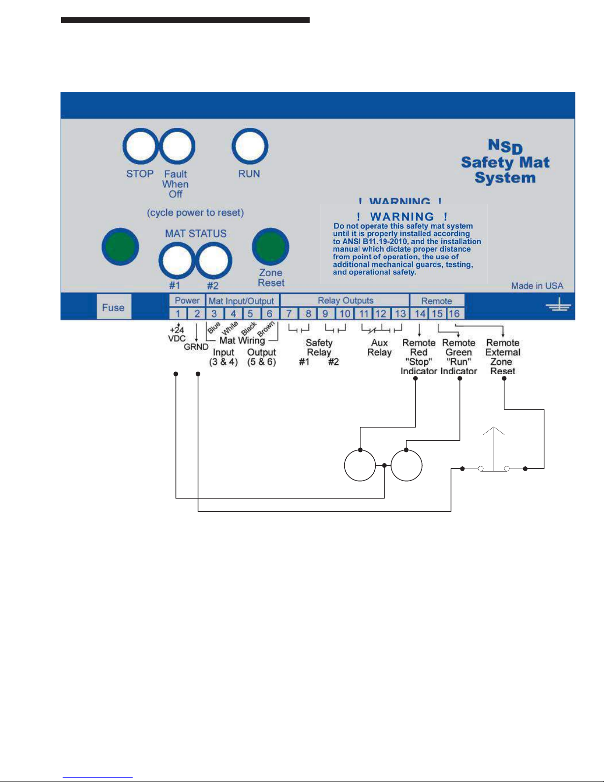
NSD-DR-04 (DIN-rail Controller with diagnostics)
Installation and Operation
NSD Safety Mat System
External Relay Checking (optional usage)
NOTE: Terminal #6 (INPUT/OUTPUT PLUG) is internally connected to Terminal #1 (POWER/OUTPUT)
plug. This allows Terminal #6 to provide +24v to the lights for the RSD (Remote Status Display).
NOTE: Canadian market wiring is black, red, red, black with 18-guage wiring size.
REMOTE STATUS DISPLAY
Green: Terminal #8 (INPUT/OUTPUT)
Red: Terminal #7 (INPUT/OUTPUT)
Black: Terminal #1 (POWER/OUTPUT)
White/Black: Terminal #3 (INPUT/OUTPUT) / Terminal #2 (POWER/OUTPUT)
12cond cable: J1 (on left side of diagnostics display)
10
Page 16

Installation and Operation
NSD Safety Mat System
NSD-DR-04 (DIN-rail Controller with diagnostics)
Accessible Connections
J1 Diagnostics display plug (used by remote status display option)
The Plug is located under the top cover on the left side of the controller
External:
POWER/OUTPUT PLUG
Terminal No. Usage
1,2,3 +POS, -NEG, EARTH GROUND (24VDC ONLY)
4,5 Safety relay N.O. output (dry contact) (held closed when GREEN)
6,7 Safety relay N.O. output (dry contact) (held closed when GREEN)
8,9,10 Auxiliary relay N.C., COM, N.O.
11,12 Fault relay N.O. (open when faulted)
INPUT / OUTPUT PLUG
Terminal No. Usage
1,2 +pos, -neg External relay checking (option)
24vdc applied across these terminals when external relay is de-energized
3 Remote external zone reset (Ground to reset zone)
4,5 Auxiliary inputs (Ground to activate feature)
6 +24vdc input (Common for terminals 3,4,5) (jumper from term #1 Power/Output)
7 Optional remote RED “STOP” indicator output (Grounded when RED)
8 Optional remote GREEN “RUN” indicator output (Grounded when GREEN)
MAT 1,2,3,4 INPUT
Terminal No. Usage
1,2 20VDC output to mat (1=blue, 2=white)
voltage between 1 & 2 alternates
(1=black, 2=red for single two-dual lead mats)
3,4 Return from mat (3=black, 4=brown)
(3=red, 4=black for single two-dual lead mats)
DEVICENET PLUG (DB-9 female)
Terminal No. Usage
2,7 CANL, CANH (twisted pair data lines)
3,6 Ground
NOTE: Canadian market wiring is black, red, red, black with 18-guage wiring size.
11
Page 17

NSD-DR-04 (DIN-rail Controller with diagnostics)
Board Connector Layout
J2,J26 MAT INPUT #1 thru #4 JP1,2 NUMBER OF MATS SELECTION
J1 DIAGNOSTICS DISPLAY (remote) JP3 MANUAL
J120 POWER/OUTPUT JP4-6 EXT, AUX1, AUX2
D13,14 Safety relay output on (closed) D3 +12v supply
D16 Auxiliary relay output on D1 +5v supply
D15 Fault relay output on (closed) D23 +20v supply
Installation and Operation
NSD Safety Mat System
NSD-DR-04 (DIN-rail Controller with Diagnostics)
Jumper Settings
1= jumper install
Number of Mats:
JP2 JP1
0 0 1 mat
1 0 2 mats
0 1 3 mats
1 1 4 mats
JP3
1= Manual relay reseting
0= Automatic relay reseting
JP4
1= External relay checking enabled
0= Disabled
JP5
Not used at this time
JP6
Not used at this time
12
Page 18

Appendix “A”
Troubleshooting
NSD-TR-01 (Metal Box) and
NSD-DR-01 (Basic DIN-rail) Controllers
PROBLEM: No indicators are lit
Cause(s): 1) Incorrect line voltage OR no line
voltage.
2) Incorrectly wired.
3) Blown fuse.
4) Bad regulator.
Cure: Check fuse, then make sure you
have line voltage present at the
correct terminals and that its within
specifi cations. If it all checks out, then
the control board must be replaced.
PROBLEM: NSD control will not go green when
reset, relay fault LED is off
Cause(s): 1) Noise on the power line caused a
glitch in the NSD control.
2) Relay contact stayed closed when
user stepped on mat.
3) One of the redundant control
circuits is faulty.
Cure: Remove power to unit for 30 seconds,
apply power and hit the RESET button.
This should reset the circuits and the
NSD control should come back up.
Check the relays for signs of contact
pitting. Also, it’s possible that large
voltage spikes on the power line could
have caused a glitch in the NSD control
and it shut down. If the unit continues
have this problem, install MOV’s on the
power terminals of any nearby motors,
or solenoids. These devices cause
noise on the power line and the MOV’s
can usually cure this.
PROBLEM: NSD control will not go green when
reset, wire fault LED is off
Cause(s): 1) Wires from mat have not been
installed correctly.
2) One or more of the four wires going
out to the mat has been cut.
Cure(s): 1) See wiring diagram page for mat
wire colors and terminals.
2) Repair or replace cut wires.
PROBLEM: NSD control will not go green when
reset, all internal indicators are on
Cause(s): 1) Object on mat is keeping control
RED.
2) Short in either the mat or external
wires going to the mat.
3) You forgot to press the RESET
button to reset the mat.
Cure: Remove the mat wires from the control
unit and use an OHM meter to check for
a short between the wires or between
each pair of wires on the mat. If there
is a short, check for physical signs of
damage to the wiring or the mat. The
mat will require replacement if the short
is not in the wiring.
NSD-DR-04
(DIN-rail Controller with diagnostics)
PROBLEM: Mat wiring fault
Cause(s): 1) Low voltage on input that should
be ground.
2) High voltage on input that should
be ground.
Cure: Bad wiring, bad comparator, or bad mat.
PROBLEM: Circuit fault
Cause(s): 1) Voltage to mat below low setpoint.
2) V oltage to mat below high setpoint.
3) One of the redundant circuits
indicates ON mat, the other
indicates OFF mat.
4) One of the redundant circuits
indicates OFF mat, the other
indicates ON mat.
5) High voltage on input that should
be ground.
Cure: Bad wiring, bad comparator, or bad mat.
PROBLEM: Zone # out of sequence
Cause: The master and slave processors
disagree on which sequence they are
on.
Cure: An external electrical noise could be
causing one of the processors to loose
sequence.
AA - 1
Page 19

Appendix “A”
Troubleshooting
PROBLEM: Zone 1 relay off, should be on
Cause(s): Relay found in the wrong state; circuitry
failure or relay failure.
Cure: Call for assistance.
PROBLEM: External relay contact welded/cut
Cause: External relay check input remained
open (0 volts) while the zone was deenergized.
Cure: When the zone is de-energized (RED),
your external relay must close within
1/4 second.
PROBLEM: External relay contact short
Cause: External relay check input remained
closed (voltage applied) while the zone
was energized.
Cure: When the zone is energized, the
secondary pole of your external relay
(N.C.) must open up within 1/4 second.
PROBLEM: Mat # out of sequence
PROBLEM: Serial data corrupted
Cause: Electrical noise getting into the control
box causing one of the computer to
reset.
Cure: Place MOV’s across the coil of any
device (outside this control) switched
on/off by the relay outputs of this
controller.
PROBLEM: Serial data transmission incomplete
Cause: Electrical noise getting into the control
box causing one of the computer to
reset.
Cure: Place MOV’s across the coil of any
device (outside this control) switched
on/off by the relay outputs of this
controller.
PROBLEM: Master relay on, Slave relay off
Cause(s): The master processor disagrees with
the slave.
Cure: Call for assistance.
Cause: The master and slave processors
disagree on which sequence they are
on.
Cure: Could have an electrical noise problem
causing one of the processors to loose
sequence.
PROBLEM: Ram failure
Cause: Microprocessor failed the internal
memory test.
Cure: Call for assistance.
PROBLEM: Power failure
Cause: Circuitry failure; brown out.
Cure: Call for assistance.
PROBLEM: Watchdog failure
Cause: Watchdog circuitry failure.
Cure: Call for assistance.
PROBLEM: Slave relay on, Master relay off
Cause: The slave processor disagrees with the
master.
Cure: Call for assistance.
AA - 2
Page 20

Appendix “A”
Troubleshooting
DeviceNet
Applicable for the DIN-rail (with diagnostics) only
Vendor ID code = 0459
Diagnostics Display
“OK U”
Devicenet unconnected (may be unplugged from
network)
“OK C”
Devicenet connected but not allocated (passed
duplicated mac id check)
“OK A”
Devicenet allocated (in service)
“OK F”
Devicenet faulted out (mat controller will work, but
not devicenet)
User adjustable MAC_ID
(default = 63)
If the NSD controller fi nds a duplicate MAC_ID,
it will go off-line and display the current MAC_ID
on the diagnostics display. Use the Fault Reset
button to decrement the MAC_ID to a new (unused)
value. Hold the button in for 2 sec to program it
permanently.
The NSD controller will now check for duplicate
MAC_ID’s using the new ID.
Network adjustable BAUD_RATE
(default = 125Kb/s)
If your network runs at different baud rate, you can
adjust the NSD controller using standard DeviceNet
set commands. The NSD controller supports 125,
250, and 500Kb/s rates. After you change the Baud
rate, you must cycle power to NSD to re-enable
Devicenet.
Network settable CONNECTION
(default= offl ine)
Network adjustable EPR_RATE timer
(default= 10sec for explicit connection, none for
bit-strobe)
The EPR (Extendend packet rate) timer is set in
250msec increments. A value of less than 250 will
keep the connection forever.
Bit_Strobe Return Values: (4 bytes returned)
BYTE 0: Status Code
Value Defi nition
0 Off all mat
1 On at least one mat
5 Waiting for Fault Reset button to be
pushed
6 Fault reset button held down
10-19 Mat fault codes
21-26 Relay fault codes
27-32 External relay fault codes
34 Ram failure
35 Power on reset
36 Clock / watchdog failure
37 Data exchange with Slave computer
corrupted
38 Data exchange with Slave not
completed
Byte 1: Zone Status
Defi nition:
0=relays off / contacts open;
1=relays on / contacts closed
Bit 7 Bit 6 Bit 5 Bit 4 Bit 3 Bit 2 Bit 1 Bit 0
Zone Zone Zone
#3 #2 #1
Byte 2: Mat Status
Defi nition: 0=on mat;1=off mat
Bit 7 Bit 6 Bit 5 Bit 4 Bit 3 Bit 2 Bit 1 Bit 0
Mat Mat Mat Mat Mat Mat Mat Mat
#8 #7 #6 #5 #4 #3 #2 #1
Byte 3: Options Enabled
Defi nition: 0=disabled, 1=enabled
Bit 7 Bit 6 Bit 5 Bit 4 Bit 3 Bit 2 Bit 1 Bit 0
Re- Re- Re- Aux Aux Mute- Ext. Manual
served served served #2 #1 out Relay Reset
Ckg.
The NSD controller will allow EXPLICIT and BIT_
STROBE connections only
AA - 3
Page 21

Appendix “B”
Safety Guidelines for Management
Safety Guidelines for Management
Operational Safety
1. Appoint a Safety Coordinator to be responsible
for safety regulations, requirements, and
suggestions. He must review and investigate
all accidents and “close calls.”
2. Establish and issue safety rules. Inform each
employee of his responsibilities. Make sure he
understands them and knows what is expected
of him.
3. A thorough review and an early inspection must
be made of existing presses, dies, and point
of operation guarding to attain the degree of
responsibility required by ANSI B11.1-2009
Safety Standards and Federal State laws.
Review what mandatory modifications are
necessary.
4. Equipment that is no longer safe and that cannot
be economically upgraded should be destroyed.
5. Never allow persons legally under age to
operate or assist in the operation of machinery .
6. All personnel must be properly trained to
eliminate accidents and injuries.
7. Regardless of the operator’s experience,
education, or language barrier, it is the
responsibility of the supervisor to give him
a thorough explanation with each new job
assignment.
8. No employee should be given a work assignment
that he does not fully understand. Only properly
instructed and thoroughly trained personnel
should be assigned to work on or with any
machine.
9. It shall be the responsibility of the employer
to provide an adequate, clean, safe, and
uncluttered work area around each machine.
10. If a malfunction is reported, stop the machine
immediately , correct the problem, then resume
production.
11. Investigate all accidents and close calls.
Analyze the reason for occurrence. T ake action
to prevent recurrence. Keep records of the
investigation and preventative steps that were
taken.
12. Only employees who understand the machines,
operation and safety requirements, and who are
able to communicate this knowledge should
be given the responsibility of instructing and
training others to perform as operators.
13. Management must decide that personnel
protective safety equipment is required to
perform each job safely. Items such as safety
glasses, shoes, gloves, helmets, hand pads,
spats, protective sleeves and material handling
equipment are common in the metal working
industry . If noise levels are excessive, protective
headsets and earmuffs are recommended.
When a mat system is used to protect the operator or passerby from penetration, it must be mounted and
properly sized so it is impossible to reach under, around, or over into the hazardous point of operation zone.
Safety mat systems normally guard the front or feed area of a machine. The sides of the areas where the
safety mat does not guard must be guarded by some other means or by additional safety mats.
If the position of the safety mat(s) will allow the operator or others to place themselves between the sensing
fi eld and the hazardous area, auxiliary guards or devices such as safety light curtains, barrier guards or
devices should be used in conjunction with the safety mat(s) to prevent the operator or others from exposure
to the hazardous area.
If mechanical guards such as: polyurethane, expanded or perforated metal, hairpins, etc., are used to guard
these areas, the opening must comply with the OSHA safety distance in relationship to the openings.
After installation of point of operation guards and before a job is released for operation, a check should be
made to verify that the guard will prevent the operators hands from reaching into the point of operation or any
hazard zone. Always refer to the applicable OSHA & ANSI standard in order to assure proper compliance to
the subject machine.
! ! ! CAUTION ! ! !
AB - 1
Page 22

Appendix “B”
Safety Guidelines for Management
14. When designing point of operation guarding,
the manufacturing process should be weighed
heavily in favor of operational safety.
15. Establish safe and convenient material handling
methods and procedures.
16. Post in convenient areas the names, addresses,
and phone numbers of physicians and hospitals,
and members of the organization who are to be
called in case of emergency.
17. All equipment must be electrically connected
according to the National Electric Code and be
consistent with other accepted practices.
18. Provide adequate and proper fi re protection
equipment.
Safety Enforcement
In order to have an effective safety program,
management at all levels must enforce every safety
rule and regulation. Strong disciplinary measures are
sometimes required. They should consist of a warning,
written reprimand, work suspension, transfer, demotion,
or possibly a dismissal. All infractions must be reported
and recorded. Once an infraction in noted, it shows
that an unsafe practice or condition has existed. This
may be the result of poor planning or improper training
and instructing. The reason for the infraction should be
analyzed in order to take corrective action.
Supervisor Training
It should be the responsibility of management to instruct
their supervisors on safety, giving job instructions,
supervising operators, determining accident causes, and
building safety attitudes among the machine operators.
Accidents can occur due to inadequate training of
supervisors.
Operator Training
It shall be the responsibility of management to insure
proper training of operators. A specifi c training program
should be instituted to instruct the operator in safety,
proper usage of the equipment, and correct operational
procedure in performing each and every job. In addition
to the supervisor, the operator should be familiar with the
proper guarding of the point of operation. Never permit
an operator to start a job without complete instructions
from his immediate supervisor.
AB - 2
Page 23
WARRANTY
Manufacturer warrants that this product will be free from
defects in material and workmanship for a period of one
year from the date of shipment thereof. Within the warranty
period, manufacturer will repair or replace such products
which are returned to it with shipping charges prepaid and
which will be disclosed as defective upon examination
by the manufacturer. This warranty will not apply to any
product which will have been subject to misuse, negligence,
accident, restriction, and use not in accordance with
manufacturer’s instructions or which will have been altered
or repaired by persons other than the authorized agent or
employees of the manufacturer.
DISCLAIMER
The provisions of the paragraph “Warranty” are the sole
obligations of the manufacturer and exclude all other
warranties of merchantability, expressed or implied.
Further, there are no warranties which extend beyond the
above warranty.
LIMITATION OF LIABILITY
In the event of any claim or breach of any obligations
of manufacturer under any order, whether expressed or
implied, and particularly in the event of any claim or a breach
of the warranty or warranties contained in the paragraph
“Warranty” or of any other warranties, expressed or implied
which might, despite the paragraph entitled “Disclaimer,” be
determined to be incorporated in any order, the company
shall under no circumstances be liable for any consequential
or special damages, either in law or in equity, or for losses
or expenses or claims for the same arising from the use of,
or inability to use, the products of the manufacturer for any
purpose whatsoever.
The entire machine safety
system must be tested at the start of every shift.
Machine testing should include: (1) proper machine
operation and stopping capability; and (2) verifi cation
of proper installation and settings of all point of
operation guards and devices before the operation
is released for production.
DISCLAIMER
Pinnacle Systems, Inc. does not assume liability for the
contents of this publication or the use of any products
described. Pinnacle Systems, Inc. reserves the right to
make changes to the products or any catalogs without
further notice.
ERRORS AND OMISSIONS
Information presented by Pinnacle Systems, Inc. has
been checked and is believed to be accurate; however,
no responsibility is assumed for clerical, typographical or
proofreading errors or omissions.
CHANGE IN SPECIFICATIONS
Product specifi cations and accessories may be changed
at any time based on improvements and other reasons.
It is our practice to change part numbers when published
ratings or features are changed, or when signifi cant con-
struction changes are made. However, some specifi ca-
tions of the Product may be changed without any notice.
When in doubt, special part numbers may be reassigned
to fi x or establish key specifi cations for your application.
Please consult the factory.
Page 24

Sales and Marketing Offi ces
Customer Service: (630) 443-8542
United States
Pinnacle Systems, Inc.
P.O. Box 100088
Pittsburgh, PA 15233
Toll Free Number: 800-569-7697
Direct Number: 412-262-3950
Fax: 412-262-4055
Canada
Pinnacle Systems, Inc.
8-1734 Orangebrook Court
Pickering, Ontario L1W 3G8
Toll Free Number: 888-285-8885
Direct Number: 905-831-1111
Fax: 905-831-4064
We have designed our equipment to the very highest
performance and safety standards known to the
current technological state of the art, as evidenced by
our U.S.A. and foreign patents issued and pending.
However, the installation, usage, suitability , and fi tness
of our equipment for any purpose, known or unknown,
is interdependent upon the performance of other
equipment not manufactured, installed, secured or
maintained by Pinnacle Systems, Inc.
We cannot and do not accept responsibility for any
overall system performance when factors, such as
these, are beyond our control.
www.pinnaclesystems.com
sales@pinnaclesystems.com
service@pinnaclesystems.com
 Loading...