

Page 1

Getting Started
Pro Tools|HD
Version 7.1
®
Page 2

Copyright
©2005 Digidesign, a division of Avid Technology, Inc.
All rights reserved. This guide may not be duplicated in whole
or in part without the written consent of Digidesign.
Avid, Digidesign, and Pro Tools are either trademarks or
registered trademarks of Avid Technology, Inc. in the US and
other countries. All other trademarks contained herein are the
property of their respective owners.
Product features, specifications, system requirements, and
availability are subject to change without notice.
PN 9106-18596-00 REV A 11/05
Page 3

contents
Chapter 1. Welcome to Pro Tools|HD
Pro Tools|HD Systems
Included with Pro Tools|HD Systems
Pro Tools HD Capabilities
Pro Tools Hardware Overview
System Requirements
Digidesign Registration
About the Pro Tools Guides
About www.digidesign.com
Chapter 2. Windows Installation
Installation Overview
Configuring Your Computer
Windows System Optimization
Hard Drive Configuration and Maintenance
Installing Pro Tools Hardware
Installing Pro Tools HD Software
Optional Software on the Pro Tools Installer CD
Removing Pro Tools
. . . . . . . . . . . . . . . . . . . . . . . . . . . . . . . . . . . . . . . . . . . . . . . . . . . . . 1
. . . . . . . . . . . . . . . . . . . . . . . . . . . . . . . . . . . . . . . . . . . . . . . . . . . 2
. . . . . . . . . . . . . . . . . . . . . . . . . . . . . . . . . . . . . . . . . . . . . . . . 3
. . . . . . . . . . . . . . . . . . . . . . . . . . . . . . . . . . . . . . . . . . . . . . . . . . . . . 7
. . . . . . . . . . . . . . . . . . . . . . . . . . . . . . . . . . . . . . . . . . . . . . . . . . . 10
. . . . . . . . . . . . . . . . . . . . . . . . . . . . . . . . . . . . . . . . . . . . . . . . 10
. . . . . . . . . . . . . . . . . . . . . . . . . . . . . . . . . . . . . . . . . . . . . . . . 11
. . . . . . . . . . . . . . . . . . . . . . . . . . . . . . . . . . . . . . . . . . . . . 13
. . . . . . . . . . . . . . . . . . . . . . . . . . . . . . . . . . . . . . . . . . . . . . . . . . . . . 13
. . . . . . . . . . . . . . . . . . . . . . . . . . . . . . . . . . . . . . . . . . . . . . . . 13
. . . . . . . . . . . . . . . . . . . . . . . . . . . . . . . . . . . . . . . . . . . . . . 15
. . . . . . . . . . . . . . . . . . . . . . . . . . . . . . . . . . . . . . . . . . . . . . . 20
. . . . . . . . . . . . . . . . . . . . . . . . . . . . . . . . . . . . . . . . . . . . . 26
. . . . . . . . . . . . . . . . . . . . . . . . . . . . . . . . . . . . . . . . . . . . . . . . . . . . . . 28
. . . . . . . . . . . . . . . . . . . . . . . . . . . . . . . . . . . . . . . . . . 1
. . . . . . . . . . . . . . . . . . . . . . . . . . . . . . . . . . . . . . . . . . . 2
. . . . . . . . . . . . . . . . . . . . . . . . . . . . . . . . . . . . . 19
. . . . . . . . . . . . . . . . . . . . . . . . . . . . . . . . . . 27
Chapter 3. Macintosh Installation
Installation Overview
Macintosh System Optimization
Hard Drive Configuration and Maintenance
Installing Pro Tools Hardware
Installing Pro Tools HD Software
Optional Software on the Pro Tools Installer CD
Removing Pro Tools
. . . . . . . . . . . . . . . . . . . . . . . . . . . . . . . . . . . . . . . . . . . . . . . . . . . . . 29
. . . . . . . . . . . . . . . . . . . . . . . . . . . . . . . . . . . . . . . . . . . . . . . 31
. . . . . . . . . . . . . . . . . . . . . . . . . . . . . . . . . . . . . . . . . . . . . . . . . . . . . . 42
. . . . . . . . . . . . . . . . . . . . . . . . . . . . . . . . . . . . . . . . . . . . 29
. . . . . . . . . . . . . . . . . . . . . . . . . . . . . . . . . . . . . . . . . . . . . 29
. . . . . . . . . . . . . . . . . . . . . . . . . . . . . . . . . . . . . 31
. . . . . . . . . . . . . . . . . . . . . . . . . . . . . . . . . . . . . . . . . . . . . 41
. . . . . . . . . . . . . . . . . . . . . . . . . . . . . . . . . . 42
Contents
iii
Page 4

Chapter 4. Launching and Configuring Pro Tools
Checking the System
Launching Pro Tools
Configuring Pro Tools
. . . . . . . . . . . . . . . . . . . . . . . . . . . . . . . . . . . . . . . . . . . . . . . . . . . . 43
. . . . . . . . . . . . . . . . . . . . . . . . . . . . . . . . . . . . . . . . . . . . . . . . . . . . . 46
. . . . . . . . . . . . . . . . . . . . . . . . . . . . . . . . . . . . . . . . . . . . . . . . . . . . 46
. . . . . . . . . . . . . . . . . . . . . . . . . . . . . . 43
Chapter 5. Connecting Your Studio
Setting Up Your Studio
Example Studio Setup with a Mixing Console
Example Studio Setup without a Mixing Console
Connecting Equipment with Digital Audio Ins and Outs
Connecting Effects Units
Connecting MIDI Devices
Connecting SMPTE Synchronization Devices
Connecting Ethernet Control Surfaces
. . . . . . . . . . . . . . . . . . . . . . . . . . . . . . . . . . . . . . . . . . . . . . . . . . . 59
. . . . . . . . . . . . . . . . . . . . . . . . . . . . . . . . . . . . . . . . . . . . . . . . . . 63
. . . . . . . . . . . . . . . . . . . . . . . . . . . . . . . . . . . . . . . . . . . . . . . . . . 64
Chapter 6. Working with Pro Tools
Session Basics
Transport Controls
Tracks
Region List
Navigating in a Session
Importing Data into Pro Tools Sessions
Basic Recording
Editing
Mixing
Plug-Ins
Mix Automation
Final Mixdown
. . . . . . . . . . . . . . . . . . . . . . . . . . . . . . . . . . . . . . . . . . . . . . . . . . . . . . . . . 67
. . . . . . . . . . . . . . . . . . . . . . . . . . . . . . . . . . . . . . . . . . . . . . . . . . . . . . 74
. . . . . . . . . . . . . . . . . . . . . . . . . . . . . . . . . . . . . . . . . . . . . . . . . . . . . . . . . . . . . . . 75
. . . . . . . . . . . . . . . . . . . . . . . . . . . . . . . . . . . . . . . . . . . . . . . . . . . . . . . . . . . 78
. . . . . . . . . . . . . . . . . . . . . . . . . . . . . . . . . . . . . . . . . . . . . . . . . . . 78
. . . . . . . . . . . . . . . . . . . . . . . . . . . . . . . . . . . . . . . . . . . . . . . . . . . . . . . . 83
. . . . . . . . . . . . . . . . . . . . . . . . . . . . . . . . . . . . . . . . . . . . . . . . . . . . . . . . . . . . . . . 90
. . . . . . . . . . . . . . . . . . . . . . . . . . . . . . . . . . . . . . . . . . . . . . . . . . . . . . . . . . . . . . . 93
. . . . . . . . . . . . . . . . . . . . . . . . . . . . . . . . . . . . . . . . . . . . . . . . . . . . . . . . . . . . . . 96
. . . . . . . . . . . . . . . . . . . . . . . . . . . . . . . . . . . . . . . . . . . . . . . . . . . . . . . . 97
. . . . . . . . . . . . . . . . . . . . . . . . . . . . . . . . . . . . . . . . . . . . . . . . . . . . . . . . . 97
. . . . . . . . . . . . . . . . . . . . . . . . . . . . . . . . . . . . . . . . . . 59
. . . . . . . . . . . . . . . . . . . . . . . . . . . . . . . . . . . 60
. . . . . . . . . . . . . . . . . . . . . . . . . . . . . . . . . 61
. . . . . . . . . . . . . . . . . . . . . . . . . . . . 62
. . . . . . . . . . . . . . . . . . . . . . . . . . . . . . . . . . . . 64
. . . . . . . . . . . . . . . . . . . . . . . . . . . . . . . . . . . . . . . . . 65
. . . . . . . . . . . . . . . . . . . . . . . . . . . . . . . . . . . . . . . . . . . 67
. . . . . . . . . . . . . . . . . . . . . . . . . . . . . . . . . . . . . . . 82
Appendix A. Connecting SCSI Drives
SCSI Requirements
Connecting SCSI Drives
Quick Formatting SCSI Drives
General Hard Drive Maintenance
Using Macintosh Drives on Windows Systems
Pro Tools|HD Getting Started Guide
iv
. . . . . . . . . . . . . . . . . . . . . . . . . . . . . . . . . . . . . . . . . . . . . . . . . . . . . . 99
. . . . . . . . . . . . . . . . . . . . . . . . . . . . . . . . . . . . . . . . . . . . . . . . . . 100
. . . . . . . . . . . . . . . . . . . . . . . . . . . . . . . . . . . . . . . . . 99
. . . . . . . . . . . . . . . . . . . . . . . . . . . . . . . . . . . . . . . . . . . . . 101
. . . . . . . . . . . . . . . . . . . . . . . . . . . . . . . . . . . . . . . . . . . 102
. . . . . . . . . . . . . . . . . . . . . . . . . . . . . . . . . . 104
Page 5

Appendix B. DigiTest Error Codes
. . . . . . . . . . . . . . . . . . . . . . . . . . . . . . . . . . . . . . . . . . . 105
Appendix C. Configuring MIDI Studio Setup (Windows Only)
MIDI Studio Setup
MIDI Patch Name Support
Appendix D. Configuring AMS (Mac OS X Only)
Audio MIDI Setup
MIDI Patch Name Support
Appendix E. DSP-Induced Delays in Mixing
Introduction to DSP-Induced Delay
Automatically Compensating for Delays
Manually Compensating for Delays
Delay Factors
Appendix F. TDM Mixing and DSP Usage
Benefits of TDM II
DSP Allocation
DSP Usage and Mixer Plug-Ins
DSP Usage with TDM Plug-Ins
. . . . . . . . . . . . . . . . . . . . . . . . . . . . . . . . . . . . . . . . . . . . . . . . . . . . . . 107
. . . . . . . . . . . . . . . . . . . . . . . . . . . . . . . . . . . . . . . . . . . . . . . . 109
. . . . . . . . . . . . . . . . . . . . . . . . . . . . . . . 111
. . . . . . . . . . . . . . . . . . . . . . . . . . . . . . . . . . . . . . . . . . . . . . . . . . . . . . 111
. . . . . . . . . . . . . . . . . . . . . . . . . . . . . . . . . . . . . . . . . . . . . . . . 114
. . . . . . . . . . . . . . . . . . . . . . . . . . . . . . . . . . . 115
. . . . . . . . . . . . . . . . . . . . . . . . . . . . . . . . . . . . . . . . . . 115
. . . . . . . . . . . . . . . . . . . . . . . . . . . . . . . . . . . . . . 116
. . . . . . . . . . . . . . . . . . . . . . . . . . . . . . . . . . . . . . . . . . 117
. . . . . . . . . . . . . . . . . . . . . . . . . . . . . . . . . . . . . . . . . . . . . . . . . . . . . . . . . 119
. . . . . . . . . . . . . . . . . . . . . . . . . . . . . . . . . . . . 121
. . . . . . . . . . . . . . . . . . . . . . . . . . . . . . . . . . . . . . . . . . . . . . . . . . . . . . 121
. . . . . . . . . . . . . . . . . . . . . . . . . . . . . . . . . . . . . . . . . . . . . . . . . . . . . . . . 123
. . . . . . . . . . . . . . . . . . . . . . . . . . . . . . . . . . . . . . . . . . . . . 125
. . . . . . . . . . . . . . . . . . . . . . . . . . . . . . . . . . . . . . . . . . . . . . 131
. . . . . . . . . . . . . . . . . . . 107
Appendix G. Troubleshooting
Index
Backing Up Your Work
Common Issues
Using DigiTest as a Diagnostic Tool
Performance Factors
Before You Call Digidesign Technical Support
. . . . . . . . . . . . . . . . . . . . . . . . . . . . . . . . . . . . . . . . . . . . . . . . . . . . . . . . . . . . . . . . . . . . 137
. . . . . . . . . . . . . . . . . . . . . . . . . . . . . . . . . . . . . . . . . . . . . . . . . . . 133
. . . . . . . . . . . . . . . . . . . . . . . . . . . . . . . . . . . . . . . . . . . . . . . . . . . . . . . 133
. . . . . . . . . . . . . . . . . . . . . . . . . . . . . . . . . . . . . . . . . . . . . . . . . . . . 134
. . . . . . . . . . . . . . . . . . . . . . . . . . . . . . . . . . . . . . . . . . . . . . . 133
. . . . . . . . . . . . . . . . . . . . . . . . . . . . . . . . . . . . . . . . . . 134
. . . . . . . . . . . . . . . . . . . . . . . . . . . . . . . . . . 135
Contents
v
Page 6

Pro Tools|HD Getting Started Guide
vi
Page 7

chapter 1
Welcome to Pro Tools|HD
Welcome to Pro Tools|HD. Pro Tools|HD audio
cards and interfaces bring high-definition digital audio recording, editing, signal processing,
mixing, and I/O capabilities to Pro Tools.
This guide covers installation and configuration
of Pro Tools|HD hardware and Pro Tools software on Windows and Macintosh platforms.
Pro Tools|HD Systems
Pro Tools 7.1 software supports the following
systems:
Pro Tools|HD (for PCIe) Systems
(Macintosh Only)
Pro Tools|HD (for PCIe) systems are available in
the following configurations:
Pro Tools|HD 1 (for PCIe)
• Accel Core (for PCIe) card
Pro Tools|HD (for PCI) Systems
(Windows and Macintosh)
Pro Tools|HD (for PCI) systems are available in
the following configurations:
Pro Tools|HD 1 (for PCI)
• HD Core (for PCI) card
Pro Tools|HD 2 Accel (for PCI)
• HD Core (for PCI) card
• HD Accel (for PCI) card
Pro Tools|HD 3 Accel (for PCI)
• HD Core (for PCI) card
• (2) HD Accel (for PCI) cards
Pro Tools 7.1 also supports earlier
Pro Tools|HD 2 (for PCI) and Pro Tools|HD 3
(for PCI) systems. These systems shipped with
HD Process cards instead of HD Accel cards
Pro Tools|HD 2 Accel (for PCIe)
• Accel Core (for PCIe) card
• HD Accel (for PCIe) card
Pro Tools|HD 3 Accel (for PCIe)
• Accel Core (for PCIe) card
• (2) HD Accel (for PCIe) cards
Chapter 1: Welcome to Pro Tools|HD
1
Page 8

Included with Pro Tools|HD Systems
All Pro Tools|HD systems include the following:
• Pro Tools|HD card(s)
• Pro Tools HD software
• DigiLink cable (to connect the primary
card to an audio interface)
• Multi-card systems include TDM FlexCables to connect the cards to each other
Audio Recording and Playback Capabilities
Pro Tools|HD 1 (for PCIe and PCI)
Pro Tools|HD 1 systems provide recording and
playback of 24-bit or 16-bit audio files with the
following track counts:
• Up to 96 tracks at 44.1 kHz or 48 kHz
• Up to 48 tracks at 88.2 kHz or 96 kHz
• Up to 12 tracks at 176.4 kHz or 192 kHz
All Pro Tools|HD systems also require at least
one Digidesign audio interface (sold separately).
See “Audio Interfaces” on page 5.
Pro Tools HD Capabilities
Pro Tools HD 7.1 on Windows or Macintosh
provides the following capabilities:
• Up to a total of 256 Audio tracks,
160 Auxiliary Input tracks, 64 Master Fader
tracks, 256 MIDI tracks, and 128 Instrument tracks per session
• 16-bit or 24-bit audio resolution, at sample
rates up to 192 kHz
• Non-destructive, random-access editing
and mix automation
• Audio processing with up to 5 TDM or
RTAS plug-ins per track, depending on your
computer’s capabilities
• Up to 5 hardware inserts per track
• Up to 10 sends per track
• Up to 128 internal busses for routing and
mixing
Pro Tools|HD 2 Accel and HD 3 Accel
(for PCIe and PCI)
Pro Tools|HD 2 Accel and HD 3 Accel systems
provide recording and playback of 24-bit or
16-bit audio files with the following track
counts:
• Up to 192 tracks at 44.1 kHz or 48 kHz
• Up to 96 tracks at 88.2 kHz or 96 kHz
• Up to 36 tracks at 176.4 kHz or 192 kHz
Non-HD Accel Systems
(for PCI)
Pro Tools|HD 2 and HD 3 systems (original
Pro Tools|HD systems with no HD Accel cards)
provide recording and playback of 24-bit or
16-bit audio files with the following track
counts:
• Up to 128 tracks at 44.1 kHz or 48 kHz
• Up to 64 tracks at 88.2 kHz or 96 kHz
• Up to 24 tracks at 176.4 kHz or 192 kHz
The number of simultaneous tracks of audio recording or playback depends on the type of
Pro Tools|HD system.
Pro Tools|HD Getting Started Guide
2
Page 9

Pro Tools Hardware Overview
This section describes each hardware component of a Pro Tools|HD system. The number of
Pro Tools|HD cards in your system will differ depending on your system configuration.
Pro Tools|HD (for PCIe) Hardware
Accel Core (for PCIe) Card
All Pro Tools|HD (for PCIe) systems include an
Accel Core (for PCIe) card.
The Accel Core (for PCIe) card provides up to 96
tracks of direct-to-disk recording and playback,
as well as DSP power for mixing and plug-in processing. The Accel Core (for PCIe) card supports
up to 24-bit and up to 192 kHz sessions.
DigiLink
DigiSerial
Accel Core (for PCIe) card
DigiLink Port The Accel Core (for PCIe) card includes a single DigiLink port for connecting up
to 32 channels of audio input and output to
your Pro Tools|HD system.
HD Accel (for PCIe) Card
The HD Accel (for PCIe) card is included in
Pro Tools|HD 2 Accel (for PCIe) and
Pro Tools|HD 3 Accel (for PCIe) systems. The
HD Accel (for PCIe) card is an expansion card,
and requires the presence of at least one Accel
Core (for PCIe) card.
The HD Accel (for PCIe) card provides additional channels of direct-to-disk recording and
playback, as well as additional DSP power for
mixing and plug-in processing. The HD Accel
(for PCIe) card supports sessions up to 24-bit
and up to 192 kHz.
DigiLink
HD Accel (for PCIe) card
DigiLink Port The HD Accel (for PCIe) card includes a single DigiLink port for connecting up
to 32 channels of audio input and output to
your Pro Tools|HD system.
DigiSerial Port The DigiSerial port on the HD Accel (for PCIe) card does not offer any functionality.
DigiSerial Port The DigiSerial port on the
Accel Core (for PCIe) card is for connecting a
Digidesign SYNC I/O. This connector is an 8-pin
mini-DIN.
The DigiSerial port on an Accel Core
(for PCIe) card does not support MachineControl connections.
Chapter 1: Welcome to Pro Tools|HD 3
Page 10

Pro Tools|HD (for PCI) Hardware
HD Accel (for PCI) Card
HD Core (for PCI) Card
All Pro Tools|HD (for PCI) systems include an
HD Core (for PCI) card.
The HD Core (for PCI) card provides up to 96
tracks of direct-to-disk recording and playback,
as well as DSP power for mixing and plug-in processing. The HD Core (for PCI) card supports up
to 24-bit and up to 192 kHz sessions.
DigiLink
DigiSerial
HD Core (for PCI) card
DigiLink Port The HD Core (for PCI) card includes a single DigiLink port for connecting up
to 32 channels of audio input and output to
your Pro Tools|HD system.
DigiSerial Port The DigiSerial port on the HD
Core (for PCI) card is for connecting a Digidesign SYNC I/O. This connector is an 8-pin miniDIN.
The DigiSerial port on an HD Core (for PCI)
card does not support MachineControl connections.
The HD Accel (for PCI) card is included in
Pro Tools|HD 2 Accel (for PCI) and
Pro Tools|HD 3 Accel (for PCI) systems. The
HD Accel (for PCI) card is an expansion card,
and requires the presence of at least one
HD Core (for PCI) card.
The HD Accel (for PCI) card provides additional
tracks of direct-to-disk recording and playback,
as well as additional DSP power for mixing and
plug-in processing. The HD Accel (for PCI) card
supports sessions up to 24-bit and up to
192 kHz.
DigiLink
HD Accel (for PCI) card
DigiLink Port The HD Accel (for PCI) card includes a single DigiLink port for connecting up
to 32 channels of audio input and output to
your Pro Tools|HD system.
DigiSerial Port The DigiSerial port on the HD Accel (for PCI) card does not offer any functionality.
If your HD Core (for PCI) card has two
DigiSerial ports, use the DigiSerial port closest to the DigiLink connector.
Pro Tools|HD Getting Started Guide4
Page 11

TDM FlexCable
Audio Interfaces
The TDM FlexCable is used to connect a pair of
cards in your Pro Tools system so they can share
data along the TDM bus. One FlexCable comes
with each expansion card.
The TDM FlexCable is a flexible printed
circuit board with delicate traces. Do not
overbend, twist, or pinch the cable. Doing
so may cause unpredictable behavior in
Pro Tools as well as harm to your system.
TDM FlexCable
To record and play audio you must have at least
one of the following Digidesign audio interfaces:
192 I/O Audio Interface
• Supports sample rates up to 192 kHz. (At least
one 192 I/O or 192 Digital I/O must be connected to your Pro Tools|HD system for
192 kHz recording, processing, and playback.)
• Supports both analog and digital connections, including AES/EBU, S/PDIF, TDIF, and
ADAT Optical:
• Digital (Digital I/O Card): 8 channels, DB25 (AES/EBU and TDIF), or one pair of
Lightpipe (ADAT Optical) connectors. Expandable up to 16 channels digital I/O
with the addition of the 192 Digital expansion card.
• Analog: 8 channels, DB-25 (balanced) connectors, inputs selectable between +4 dBu
or –10 dBV, outputs +4 dBu only. Expandable up to 16 analog inputs or 16 outputs
using an optional 192 AD or 192 DA expansion card, respectively.
• Digital (Enclosure): 2 channels, XLR
(AES/EBU) connectors; 2 channels RCA
(S/PDIF) connectors.
• Optical (Enclosure): 8 channels, one pair of
Lightpipe (ADAT Optical) connectors (switchable to 2 channels, S/PDIF).
• Loop Sync In and Out for connecting
Pro Tools|HD interfaces and peripherals
• External Clock In and Out receive or send 1x
Word clock (configurable to 256x for Legacy
support, see “Optional Legacy I/O Audio Interfaces” on page 7).
Chapter 1: Welcome to Pro Tools|HD 5
Page 12

192 Digital I/O Audio Interface
• Supports sample rates up to 192 kHz. (At least
one 192 I/O or 192 Digital I/O must be connected to your Pro Tools|HD system for
192 kHz recording, processing, and playback.)
• Supports digital connections, including
AES/EBU, S/PDIF, TDIF, and ADAT Optical:
• Digital (2 Digital I/O Cards): 16 channels,
DB-25 (AES/EBU and TDIF), or two pairs of
Lightpipe (ADAT Optical) connectors.
• Digital (Enclosure): 2 channels, XLR
(AES/EBU) connectors; 2 channels RCA
(S/PDIF) connectors.
• Optical (Enclosure): 8 channels, one pair of
Lightpipe (ADAT Optical) connectors (selectable to 2 channels, S/PDIF).
• Loop Sync In and Out for connecting
Pro Tools|HD interfaces and peripherals
• External Clock In and Out receive or send 1x
Word clock (configurable to 256x for Legacy
support, see “Optional Legacy I/O Audio Interfaces” on page 7).
96 I/O Audio Interface
• Supports sample rates up to 96 kHz.
• Supports analog and digital connections, including AES/EBU, S/PDIF, and ADAT optical:
• Analog: 8 channels, 1/4-inch TRS (balanced or unbalanced) connectors, +4 dBu
or –10 dBV
• Digital: 2 channels, XLR (AES/EBU) connectors; 2 channels, RCA (S/PDIF) connectors
• Optical: 8 channels, one pair of Lightpipe
(ADAT Optical) connectors (switchable to 2
channels, S/PDIF)
• External Clock In and Out receive or send
1x Word clock (configurable to 256x for
Legacy support, see “Optional Legacy I/O
Audio Interfaces” on page 7)
96i I/O Audio Interface
• Supports sample rates up to 96 kHz
• 16 discrete channels of input, and 2 channels
of output, with 4-segment LED meters on
each channel. Audio inputs and outputs include:
• 16 channels of 24-bit, 96-kHz capable analog input, with adjustable input sensitivity
•2 channels of 24-bit, 96-kHz capable analog output, with selectable operating level
•2 channels of 24-bit, 96 kHz-capable digital
S/PDIF RCA input and output
• Loop Sync In and Out for connecting
Pro Tools|HD interfaces and peripherals
• External Clock In and Out receive or send 1x
Word clock
Pro Tools|HD Getting Started Guide6
Page 13

Optional Legacy I/O Audio Interfaces
For additional input and output channels, older
Digidesign audio interfaces (or Legacy I/Os) can
be connected to the 192 I/O, 192 Digital I/O, or
96 I/O (the 96i I/O does not support Legacy interfaces). The following supported legacy interfaces can only be used with 44.1 kHz or 48 kHz
sessions:
888|24 I/O Audio Interface
• Analog: 8 channels, XLR (balanced or unbalanced) connectors, selectable between +4 dBu
or –10 dBV
• Digital: 8 channels, XLR (AES/EBU) connectors; 2 channels, RCA (S/PDIF) connectors
882|20 I/O Audio Interface
• Analog: 8 channels, 1/4-inch TRS (balanced or
unbalanced) connectors, selectable between
+4 dBu and –10 dBV
• Digital: 2 channels, RCA (S/PDIF) connectors
1622 I/O Audio Interface
• Analog: 16 input channels and 2 output channels, 1/4-inch TRS (balanced or unbalanced)
connectors. Inputs are selectable from +4 dBu
to –10 dBV line levels and higher in 2 dB gain
steps; outputs are selectable between +4 dBu
or –10 dBV.
• Digital: 2 channels, RCA (S/PDIF) connectors.
Digidesign 24-bit ADAT Bridge I/O
• Optical: 16 channels, a pair of Lightpipe
(ADAT) connectors.
• Analog output: 2 channels, 1/4-inch TRS (balanced) connectors, selectable between +4 dBu
and –10 dBV.
• Digital: 2 channels, XLR (AES/EBU); 2 channels RCA (S/PDIF) connectors.
System Requirements
Pro Tools|HD system hardware and supported
audio interfaces can be used with a Digidesignqualified Windows or Macintosh computer running Pro Tools HD software.
For complete system requirements, visit the
compatibility page of the Digidesign Web site
(www.digidesign.com/compato).
Compatibility Information
Digidesign can only assure compatibility and
provide support for hardware and software it
has tested and approved.
For a list of Digidesign-qualified computers, operating systems, hard drives, and third-party devices, refer to the latest compatibility information on the Digidesign Web site
(www.digidesign.com/compato).
MIDI Requirements
USB MIDI interfaces work effectively with
Pro Tools systems on Windows or Macintosh.
Serial MIDI interfaces are supported on Windows systems only.
Only USB MIDI interfaces are compatible
with Pro Tools systems for Mac OS X.
Modem-to-serial port adapters and serial
MIDI devices are not supported.
For a list of supported adapters, refer to the
Digidesign Web site (www.digidesign.com).
Chapter 1: Welcome to Pro Tools|HD 7
Page 14

Hard Drive Requirements
SCSI Hard Drives
For optimal audio recording and playback, all
Pro Tools|HD systems require one or more Digidesign-qualified drives.
Avoid Recording to the System Drive
Recording to your system drive is not recommended. Recording and playback on a system
drive may result in lower track counts and fewer
plug-ins.
Digidesign does not recommend recording
to a system drive. Record to a system drive
only when necessary.
Drive Formats
Windows Windows XP systems should use drives
formatted with as NTFS or FAT32 (NTFS preferred).
Macintosh Macintosh systems should use drives
formatted with HFS or HFS+ file system only.
The UNIX File System (UFS) is not supported with Pro Tools on Mac OS X.
Hard drive performance depends on factors including system configuration, number of tracks,
session sample rate, density of edits, and the use
of crossfades and other processes such as Beat
Detective in a session.
Be sure to check the latest compatibility information on the Digidesign Web site for drive requirements (www.digidesign.com/compato).
Digidesign recommends qualified SCSI hard
drives and a qualified SCSI host bus adapter
(HBA) card or (on Windows systems) a qualified
built-in SCSI HBA connector on the motherboard.
For complete information on track count and
the supported number and configuration of
SCSI drives, refer to the Digidesign Web site
(www.digidesign.com/compato).
FireWire Hard Drives
Digidesign recommends qualified FireWire
drives and (on Windows systems) a qualified
FireWire host adapter.
For complete information on track count and
the supported number and configuration of
FireWire drives, refer to the Digidesign Web site
(www.digidesign.com/compato).
IDE/ATA/SATA Hard Drives
A qualified internal IDE/ATA/SATA drive may be
used as a dedicated audio drive.
For complete information on track count with
internal drives, refer to the Digidesign Web site
(www.digidesign.com/compato).
IDE/ATA/SATA hard drives provide limited
track count performance and are not supported when an Expansion Chassis is used.
For more information regarding Expansion
Chassis operating procedures, see the
Pro Tools Expanded Systems Guide.
Pro Tools|HD Getting Started Guide8
Page 15

Hard Disk Storage Space
Mono audio tracks recorded with 16-bit resolution at 44.1 kHz (CD quality) require approximately
5 MB of hard disk space per minute. The same tracks recorded with 24-bit resolution require about
7.5 MB per minute.
Table 2 lists the required disk space for certain track numbers and track lengths, to help you estimate
your hard disk usage.
Table 2. Required hard drive space for audio tracks
Number of
tracks and
length
16-bit at
44.1 kHz
16-bit at
48 kHz
24-bit at
44.1 kHz
24-bit at
48 kHz
16-bit at
88.2 kHz
16-bit at
96 kHz
24-bit at
88.2 kHz
24-bit at
96 kHz
1 mono track
1 minute
1 stereo track
5 minutes
1 stereo track
60 minutes
32 mono tracks
5 minutes
32 mono tracks
60 minutes
5 MB 5.5 MB 7.5 MB 8.2 MB 10 MB 11 MB 15 MB 16.4 MB
50 MB 55 MB 75 MB 83 MB 100 MB 110 MB 150 MB 164 MB
600 MB 662 MB 900 MB 991 MB 1.2 GB 1.3 GB 1.8 GB 2 GB
800 MB 883 MB 1.2 GB 1.4 GB 1.6 GB 1.8 GB 2.4 GB 2.8 GB
9.4 GB 10.4 GB 14 GB 15.5 GB 18.8 GB 20.8 GB 28 GB 31 GB
Chapter 1: Welcome to Pro Tools|HD 9
Page 16

Digidesign Registration
Review the enclosed registration information
card and follow the instructions on it to quickly
register your purchase online. Registering your
purchase is the only way you can be eligible to
receive complimentary technical support and
future upgrade offers. It is one of the most important steps you can take as a new user.
Conventions Used in This Guide
Digidesign guides use the following conventions to indicate menu choices and key commands:
:
Convention Action
File > Save Choose Save from the File
menu
Control+N Hold down the Control key
and press the N key
About the Pro Tools Guides
In addition to the printed guides included with
your system, PDF versions of the Pro Tools
guides are installed automatically with
Pro Tools. The main guides (such as the Reference Guide and the Menus Guide) are accessible
from the Pro Tools Help menu. To view or print
the PDF guides, you can use Adobe Reader or Apple Preview.
Control-click Hold down the Control key
and click the mouse button
Right-click (Windows) Click with the right mouse
button
The following symbols are used to highlight important information:
User Tips are helpful hints for getting the
most from your system.
Important Notices include information that
could affect your data or the performance of
your system.
Shortcuts show you useful keyboard or
mouse shortcuts.
Cross References point to related sections in
Digidesign guides.
Pro Tools|HD Getting Started Guide10
Page 17

About www.digidesign.com
The Digidesign Web site (www.digidesign.com)
is your best source for information to help you
get the most out of your Pro Tools system. The
following are just a few of the services and features available.
Registration Register your purchase online. See
the enclosed registration form for instructions.
Support Contact Digidesign Technical Support
or Customer Service; download software updates and the latest online manuals; browse the
Compatibility documents for system requirements; search the online Answerbase; join the
worldwide Pro Tools community on the Digidesign User Conference.
Training and Education Become a certified
Pro Tools Operator or Expert; study on your
own using courses available online, or find out
how you can learn in a classroom setting at a
certified Pro Tools Training Center.
Products and Developers Learn about Digidesign
products; download demo software; learn about
our Development Partners and their plug-ins,
applications, and hardware.
News and Events Get the latest news from
Digidesign; sign up for a Pro Tools demo.
To learn more about these and other resources
available from Digidesign, visit the Digidesign
Web site (www.digidesign.com).
Chapter 1: Welcome to Pro Tools|HD 11
Page 18

Pro Tools|HD Getting Started Guide12
Page 19

chapter 2
Windows Installation
This chapter contains information for Windows
systems only. If you are installing Pro Tools on a
Macintosh computer, see Chapter 3, “Macintosh Installation.”
Before installing this version of Pro Tools,
refer to the Read Me information included
on the Pro Tools Installer CD.
Installation Overview
Installation of a Pro Tools|HD system on a Windows computer includes the following steps:
1 “Configuring Your Computer” on page 13.
2 “Windows System Optimization” on page 15.
3 “Installing Pro Tools Hardware” on page 20.
4 “Installing Pro Tools HD Software” on
page 26.
5 “Connecting Audio Interfaces” on page 22.
Configuring Your Computer
To ensure optimum performance with
Pro Tools|HD, configure your computer before
installing Pro Tools hardware and software.
Before you make any changes to your computer’s system settings, make a backup copy
of your registry (where many of these essential settings are stored). By doing so, you
will be able to restore your system’s original
settings if problems arise. Consider using a
disk recovery utility such as Norton Ghost
for additional security. See your
Windows XP documentation for details.
Configuring the System BIOS
BIOS (Basic Input/Output System) parameters
vary depending on the make and model of the
computer. Refer to the documentation that
came with your computer for details.
6 “Launching and Configuring Pro Tools” on
page 43.
7 “Connecting Your Studio” on page 59.
The names and options that appear in your
computer’s system BIOS may differ slightly from
those described in this section.
If your computer does not have the BIOS
configuration options included in this section, or if you do not feel comfortable
changing system BIOS parameters, consult
a Windows system administrator, computer
dealer, or manufacturer for assistance.
Chapter 2: Windows Installation 13
Page 20

To modify your computer’s system BIOS:
1 Start or restart the computer.
2 While the computer is starting up, enter BIOS
Setup by pressing the appropriate key (usually
indicated in the startup message) on the computer keyboard. The F1, F2, or the Delete keys
are commonly used.
3 In the appropriate page of the BIOS Setup, dis-
able PCI Parity. If the PCI Parity option isn’t
available on your computer, skip this step.
4 If you will be using SCSI drives or devices, and
your computer is equipped with built-in SCSI
hardware, enable SCSI support. SCSI support parameters are typically found on the Devices &
I/O Options page of the BIOS setup utility. If you
do not have built-in SCSI hardware and are using a SCSI host bus adapter (HBA) card instead,
you do not need to enable SCSI support.
5 Disable Power Management, if present.
6 Enable PCI Dynamic Bursting, if present.
7 Save the new BIOS settings.
Modifying the Computer’s SCSI BIOS
To modify your computer’s SCSI BIOS:
1 Start or restart the computer.
2 While the computer is starting up, when the
text message regarding the SCSI BIOS appears,
press the key combination listed on the screen
to enter the SCSI BIOS setup utility.
3 Refer to your SCSI host bus adapter card doc-
umentation to set the following parameters:
• For each SCSI ID and SCSI channel connected to your audio drives, set the Maximum Sync Transfer Rate parameter to
20 MB/sec for the ATTO EPCI-DC, or to Ultra 160 for Ultra 160 cards.
• If you are using an ATTO host bus adapter
card, change the PCI Burst Size to 128 Bytes
and the Burst Length Selection Timeout to
16 ms (UL3D only).
4 Save the new SCSI BIOS settings.
5 Exit SCSI BIOS setup and restart the computer.
8 Exit BIOS setup and restart the computer.
Configuring the SCSI BIOS
If you are using SCSI drives or devices, you must
modify the settings of your built-in SCSI hardware or SCSI host bus adapter card. This allows
SCSI hard drives and devices to work properly
with Pro Tools. This procedure varies on different computers. Refer to the documentation that
came with your computer.
Pro Tools|HD Getting Started Guide14
Updating the ATTO SCSI BIOS
(ATTO SCSI HBA Cards Only)
If you are using an ATTO SCSI HBA card, you
may need to update its SCSI BIOS. When starting your computer, you will see the version
number of the currently installed ATTO SCSI
BIOS. If it is not version 1.68 or higher, you
must update the SCSI BIOS.
The following procedure uses a floppy disk
as a DOS boot disk. You can use another
type of bootable media if available.
Page 21

To update the BIOS on the ATTO SCSI card:
1 Insert a PC-formatted floppy disk in your
floppy drive (this needs to be a DOS boot disk).
2 Copy the DOS folder from the ATTO folder on
the Pro Tools Installer CD-ROM to the floppy
disk.
3 Shut down the computer.
4 Disconnect any hard drives connected to the
SCSI card.
5 Start the computer with the floppy disk in the
floppy drive.
6 From within DOS, change directory to the
DOS/UTILITY folder and run flash.bat.
7 When prompted with the Update MAC, PC
Setup Program message, type Y for Yes and press
Enter.
The SCSI BIOS update may take a few
minutes.Do not interrupt this process or
your system may be damaged.
For more information, see the flash.txt in
the DOS/UTILITY folder.
Installing the ATTO SCSI Driver
The full name of the ATTO driver is:
■ ATTO ExpressPCI
To install the ATTO SCSI driver:
1 Start or restart the computer.
2 Insert the Pro Tools Installer CD-ROM in your
CD-ROM drive.
3 In the Additional Files\ATTO\Driver 1.68
folder, locate and click Setup.exe.
4 Follow the on-screen instructions to update
the driver on your SCSI Host Bus Adapter.
5 When Setup is finished, restart the computer.
Windows System Optimization
Before configuring your computer, make sure
you are logged in as an Administrator for the account where you want to install Pro Tools. For
details on Administrator privileges, refer to your
Windows documentation.
8 When updating is finished, remove the floppy
disk and restart the computer.
Installing SCSI Drivers
For Pro Tools to run at maximum efficiency
with SCSI Host Bus Adapters and SCSI drives, install a Digidesign approved SCSI driver.
For a list of Digidesign approved computers
and supported SCSI driver versions, refer to
to the latest compatibility information on
the Digidesign Web site
(www.digidesign.com/compato).
Required Optimizations
To ensure optimum performance with
Pro Tools, configure the following settings before you install Pro Tools software.
When you are finished changing Windows
system settings, restart your computer.
Chapter 2: Windows Installation 15
Page 22

Enabling DMA
Enabling your computer's DMA (Direct Memory
Access) frees up CPU bandwidth so the computer can do other Pro Tools tasks.
In most cases the DMA option will already be set
correctly, as Windows XP detects and activates
DMA mode by default.
To enable DMA for any IDE hard drives:
1 Choose Start > Control Panel.
2 In Classic View, double-click System.
3 Click the Hardware tab.
4 Under Device Manager, choose Device Man-
ager.
5 In the Device Manager window, double-click
IDE ATA/ATAPI controllers, then double-click
the Primary IDE Channel for your IDE hard
drive.
6 Click the Advanced Settings tab.
To configure Windows Power Management:
1 Choose Start > Control Panel.
2 Double-click Power Options.
3 Click the Power Schemes tab.
4 From the Power Schemes pop-up menu, select
Always On.
5 Click OK.
This sets System Standby, System Hibernate,
and “Turn off hard disks” to Never.
On AMD processors, be sure to check and
disable Cool N’Quiet in the System BIOS (in
the Cool & Quiet Configuration section).
Refer to the manufacturer’s documentation
for instructions on disabling this power option, if necessary.
Disabling ClearType Font Smoothing
When using Pro Tools, the Effects “Clear Type”
setting must be disabled.
7 For each device, set the Transfer Mode to
“DMA if available,” and click OK.
8 Repeat steps 5–7 for any additional IDE Chan-
nels.
9 Close the Computer Management window.
Disabling System Standby and Power Management
When using Pro Tools, the Windows System
Standby power scheme must be set to Always
On. This helps prevent long record or playback
passes from stopping due to system resources
powering down.
Pro Tools|HD Getting Started Guide16
To disable ClearType font smoothing:
1 Choose Start > Control Panel.
2 Double-click Display.
3 Click the Appearance tab.
4 Click Effects.
5 Deselect “Use the following method to
smooth edges of screen fonts.”
6 Click OK to save your settings and close the
Effects dialog.
7 Click OK.
8 Restart the computer.
Page 23

Recommended Optimizations
Pro Tools can also be affected by other software
and hardware drivers installed on your computer. It is recommended (but not required) that
you do the following:
•Avoid running any unneeded programs at
the same time as Pro Tools.
•Turn off any software utilities that run in
the background, such as Windows Messenger, calendars, and disk maintenance programs.
•Turn off any nonessential USB devices
while running Pro Tools.
• If your video display card supports it, enable Bus Mastering in the manufacturer’s
Control Panel. Refer to the manufacturer’s
instructions for details.
• If your computer is connected to a network, make sure that all mapped network
drives are available. If necessary, unmap
any network drives that are not available.
Optional Optimizations
The following system optimizations may help
Pro Tools perform better on some systems. It is
recommended that you only try these optimizations if necessary, as they may disable or adversely affect the functionality of other programs on your system.
To disable a network card:
1 Right-click My Computer and choose Man-
age.
2 Under System Tools, select Device Manager.
3 In the Device Manager window, double-click
Network adapters, then double-click the Network Adapter card you want to disable.
4 Under the General tab, choose “Do not use
this device (disable)” from the Device Usage
pop-up menu, and click OK.
5 Close the Computer Management window.
Adjusting Processor Scheduling
To Adjust Processor Scheduling Performance:
1 Choose Start > Control Panel.
2 In Classic View, double-click System.
3 Click the Advanced tab.
4 Under the Performance section, click the Set-
tings button.
5 In the Performance Options window, click the
Advanced tab.
6 Under the Processor scheduling section, select
the Background Services option.
7 Under the Memory Usage section, select the
System cache option.
Disabling Network Cards
If applicable, disable any networking cards
(other than a 1394 “FireWire” card that you
might use to connect an external drive to your
system).
8 Click OK to close the Performance Options
window.
9 Click OK to close the System Properties win-
dow.
10 Restart the computer for the changes to take
effect.
Chapter 2: Windows Installation 17
Page 24

Disabling Hyper-Threading
Pro Tools 7.0 takes advantage of the added processing power of computers that have multiple
processors, or that feature multi-core processing
or Hyper-Threading, for RTAS processing.
However, if you set the number of processors
available for RTAS processing to 1 (in the
Pro Tools Playback Engine dialog), some computers with hyperthreading capability may experience decreased performance.
If this occurs, you can increase the number of
RTAS processors in the Playback Engine dialog,
or you can disable hyper-threading on the computer.
Refer to your computer’s documentation for
steps on how to enter the computer’s BIOS and
disable Hyper-Threading.
Disabling System Startup Items
The fewer items in use by your computer, the
more resources are available for Pro Tools. Some
startup applications may be consuming unnecessary CPU resources, and should be turned off.
To disable System Startup Items:
1 From the Start menu, choose Run.
2 Type “msconfig” and click OK. The System
Configuration Utility opens.
3 Under the General tab, choose Selective Star-
tup.
4 Deselect Load Startup Items and click OK.
5 Click Restart to restart the computer.
6 After restarting, the computer displays a Sys-
tem Configuration message. Check to see if
Pro Tools performance has increased before you
deselect the “Don't show this message again”
option. If performance has not changed, run
“msconfig” and return your computer Selective
Startup back to Normal Startup. Alternatively,
try disabling Startup items and non-essential
processes individually.
If you disable any of the following startup items,
do so carefully:
• Portable media serial number (required for
applications that utilize a copy protection
key)
• Plug and play
• Event log
•Cryptographic services
• DHCP Client, TCP/IP Net BIOS, and other
networking-related items (unless the computer has no network or internet connection, in which case these items can be
disabled)
Pro Tools|HD Getting Started Guide18
Page 25

Hard Drive Configuration and
Maintenance
5 Choose a file system. For optimum perfor-
mance, audio drives should be formatted as
NTFS. (FAT32 is also supported.)
It is recommended that you start with a newly
initialized audio drive. You should also periodically defragment your audio drive to ensure
continued system performance.
Always back up any important data on
your drive before initializing it, as it will
erase all data on the drive.
Avoid Recording to the System Drive
Recording to your system drive is not recommended. Recording and playback on a system
drive may result in lower track counts or fewer
plug-ins.
Formatting an Audio Drive
To format an audio drive:
1 Right-click My Computer and choose Man-
age.
2 Under Storage, choose Disk Management.
6 Select “Perform a quick format.”
7 Make sure “Enable file and folder compres-
sion” is not selected.
8 Set the Allocation unit size to Default.
9 Click OK.
Pro Tools only supports Basic drive types.
Do not convert the drive to a Dynamic type.
10 When formatting is complete, close the For-
mat window.
Defragmenting an Audio Drive
Periodically defragment audio drives to maintain
system performance.
To defragment an audio drive:
1 Right-click My Computer and choose Man-
age.
2 Under Storage, choose Disk Defragmenter.
3 In the Disk Defragmenter window, choose the
drive you want to defragment
Disk Management window
3 In the Disk Management window, right-click
the hard drive you will use for audio and choose
Format.
4 In the Format window, name the volume.
4 Click the Defragment button and follow the
on-screen instructions.
5 When defragmenting is complete, close the
Computer Management Window.
Chapter 2: Windows Installation 19
Page 26

Installing Pro Tools Hardware
Disabling Driver Signing Warnings
Before you install Pro Tools|HD cards, temporarily disable the Driver Signing warning option.
This expedites and automates much of the installation process. If you do not temporarily disable this option, warning messages (that you are
installing an unsigned driver) will appear for
each DSP chip detected during software installation.
To disable the warning option:
1 Choose Start > Control Panel.
2 Double-click System.
3 Click the Hardware tab in the System Control
Panel.
4 Click the Driver Signing button.
5 Select “Ignore—Install the software anyway
and don’t ask for my approval.”
6 Click OK to close the Driver Signing Options
window.
Installing Pro Tools|HD Cards
This section shows how to install Pro Tools|HD
cards into a Windows computer. To install cards
into an expansion chassis, see the Expanded Sys-
tems Guide.
To install Pro Tools cards:
1 Turn off your computer and any peripherals.
Leave your computer’s power cable plugged in
so the computer is grounded.
2 Disconnect all cables attached to the com-
puter (such as hard drives, displays, USB and
FireWire devices) except for the power cable.
3 Open the computer case.
4 Remove the metal access port cover behind
the slot you want to use by removing the screw
and sliding the cover out from the access port.
Before handling any card, discharge static
electricity from your clothes or body by
touching a grounded metal surface, such as
the power supply case inside your computer.
5 Install the HD Core card in the first PCI slot.
7 Click OK to close the System Properties win-
dow.
8 Turn the computer off.
9 Proceed to “Installing Pro Tools|HD Cards” on
page 20.
Pro Tools|HD Getting Started Guide20
Page 27

6 If you are installing additional Pro Tools cards
(or other cards), skip to the next step. If you
have no additional cards to install, do the following:
• Secure the card in place with the slot access
port screw you removed earlier.
• Close the computer case.
• Skip to “Connecting Audio Interfaces” on
page 22.
7 Install the first HD Accel card (if any) in the
second PCI slot.
8 Install any remaining HD Accel cards in the
remaining consecutive PCI slots.
9 Install any HD Process cards in the remaining
consecutive PCI slots (64-bit or 32-bit).
10 If you are installing a SCSI host bus adapter
(HBA) card, install it in the highest-numbered
remaining slot.
11 Check to be sure that your cards are installed
in the proper order for your system, starting
with the lowest numeric slot:
• Display card for your computer monitor
• HD Core card
• HD Accel cards
• HD Process cards
• SCSI host bus adapter (HBA) card
Connecting Pro Tools|HD Cards
In systems that include more than one card, you
must connect all the Pro Tools|HD cards to each
other with TDM FlexCables.
Each Pro Tools|HD card has two ports along the
top of the card, labeled Port A and Port B. The
FlexCable has two connectors, also labeled
Port A and Port B, to ensure proper connection.
Data communication across multiple cards is
achieved by connecting Port B of the first card
to Port A of the next card with a TDM FlexCable.
The first FlexCable always goes from Port B
on the core card to Port A on the first
expansion card, as described in the following steps.
To connect Pro Tools|HD cards:
1 Shape the FlexCable before installing it on the
card by holding the cable with its printed side
facing you, and moving the Port B portion of
the cable straight towards you and inwards, as
shown below. Do not bend the cable more than
you need to, as you may damage the traces in
the cable.
12 Secure each card in place with the slot access
port screws you removed earlier.
Preparing TDM FlexCable for installation
Chapter 2: Windows Installation 21
Page 28

2 Slide the FlexCable into the notch of the first
card, so that the Port B connector of the FlexCable can be aligned with Port B of the first card;
and the Port A connector of the FlexCable can
be aligned with Port A of the second card, as
shown below.
Inserting TDM FlexCable
3 Connect the Port A connector of the FlexCa-
ble to Port A on the second card. Push gently but
firmly until the cable is fully connected to the
card. Attach the other end of the FlexCable (labeled Port B) to Port B on the first card.
Top view of two cards connected with TDM FlexCable
4 Verify the connection. Make sure the FlexCa-
ble ports seat flat against the sockets on the
cards, and are firmly attached.
5 For systems with more than two cards, con-
nect each additional card to its preceding card.
Use FlexCables to connect card pairs together, as
described above, until all cards are connected.
(Each HD Accel or HD Process card is packaged
with a FlexCable.)
Connecting Audio Interfaces
Each Pro Tools|HD audio interface supplies up
to 16 channels of input and output to your system. Audio interfaces are connected directly to
Pro Tools|HD cards, or through the Expansion
ports on other Pro Tools|HD interfaces.
Each Pro Tools|HD card supports up to 32 channels. To get a full 32 channels of I/O from one
card, you can connect, or daisy-chain, a second
16-channel Pro Tools|HD I/O to the first
Pro Tools|HD I/O that is connected directly to
the Pro Tools|HD card.
Pro Tools|HD supports up to a maximum of ten
192 I/Os, 192 Digital I/Os, or 96 I/Os. Up to five
96i I/Os can be used simultaneously.
For examples of connecting multiple I/Os, see
Figure 1 and Figure 2 on page 24.
Pro Tools|HD audio interfaces need room at
their sides to maintain proper air flow for
cooling. Do not block the sides of the unit or
disconnect the internal fan. If the units are
rack-mounted in a case, remove the case
lids or doors before operating the system.
Failure to do so can result in the units overheating very quickly, which can permanently damage sensitive components.
Legacy audio interfaces can also be connected to
Pro Tools|HD interfaces. See “Connecting an
Additional 16 Channels of Audio with Legacy
Audio Interfaces” on page 25.
6 Close the computer case.
7 Proceed to “Connecting Audio Interfaces” on
page 22.
Pro Tools|HD Getting Started Guide22
Page 29

To connect Pro Tools|HD audio interfaces:
1 If you are using a single 192 I/O,
192 Digital I/O, 96 I/O, or 96i I/O, connect its
Primary Port to the HD Core card with the DigiLink cable provided with the card. You must attach at least one 192 I/O, 192 Digital I/O,
96 I/O, or 96i I/O to your system in order for
Pro Tools to launch.
If you have at least one 192 I/O or
192 Digital I/O in your system configuration, it must be connected to the HD Core
card as the primary interface.
2 Connect additional Pro Tools|HD audio inter-
faces to subsequent Digidesign audio cards, or
daisy-chain the interfaces (by connecting the
Primary Port of the secondary interface to the
Expansion Port of the primary interface).
If you are connecting both 192 I/O (or
192 Digital I/O) and 96 I/O audio interfaces to
your system, connect the 192 I/O (or
192 Digital I/O) to your HD Core card, followed
by any additional 192 I/O (or 192 Digital I/O)
interfaces connected to subsequent cards. Then
connect 96 I/O interfaces to subsequent cards,
or to other interfaces, then connect 96i I/O interfaces.
Connecting Loop Sync
If you are using two or more Pro Tools|HD audio
interfaces or a SYNC I/O peripheral, Loop Sync
must be connected to maintain proper clock
among the devices.
To make Loop Sync connections:
1 Connect the Loop Sync Out of each interface
to the Loop Sync In of the next interface with
the BNC cables included in your I/O packaging.
2 Connect the Loop Sync Out of the last inter-
face to the Loop Sync In of the primary interface
or SYNC I/O peripheral.
Connecting Legacy Audio Interfaces
If you are connecting a Digidesign Legacy audio
interface, continue with “Connecting an Additional 16 Channels of Audio with Legacy Audio
Interfaces” on page 25. (The 96i I/O does not
support Legacy I/O.)
You can also connect a single Pro Tools|HD interface to each Pro Tools|HD card in your system
using the provided DigiLink cables. (However,
there is no advantage to this configuration over
daisy-chaining interfaces.)
Chapter 2: Windows Installation 23
Page 30

12-foot DigiLink cable
HD Core or
Accel Core card
18-inch DigiLink cable
Figure 1. Two 96 I/Os (32-channel system)
18-inch DigiLink cable
Loop Sync cables
Loop Sync cables
12-foot DigiLink cable
Loop Sync cables
HD Core or
Accel Core card
TDM FlexCable
12-foot DigiLink cable
Figure 2. Three 96 I/Os (48-channel system)
Pro Tools|HD Getting Started Guide24
HD Accel card
or HD Process card
Page 31
Connecting an Additional 16 Channels of Audio with Legacy Audio Interfaces
Each 192 I/O, 192 Digital I/O, and 96 I/O can
support 16 channels of audio to and from
Digidesign Legacy I/Os. (The 96i I/O does not
support Legacy I/O.) Legacy I/Os include the
888|24 I/O, 882|20 I/O, 1622 I/O, and the 24-bit
ADAT Bridge I/O.
3 To properly clock the Legacy audio interface,
connect the Ext. Clock output port on the
Pro Tools|HD I/O to the Slave Clock IN on the
Legacy audio interface. The Legacy audio interface will switch to Slave mode once the proper
clock is outputting from the Pro Tools|HD I/O.
Always use the Ext. Clock Out port of the same
I/O to which the Legacy audio interface is attached.
The original 888 I/O and 882 I/O interfaces
are not supported with Pro Tools|HD.
To connect Digidesign Legacy audio interfaces:
1 Connect the “MIX card” end of the peripheral
cable that came with your Legacy audio interface (60-pin side) to the Legacy Port on the primary Pro Tools|HD audio interface. Connect the
other end to the Computer Port on the Legacy
audio interface.
2 Connect any additional Legacy audio inter-
faces in the same manner, to Pro Tools|HD audio interfaces connected directly to HD cards.
– or –
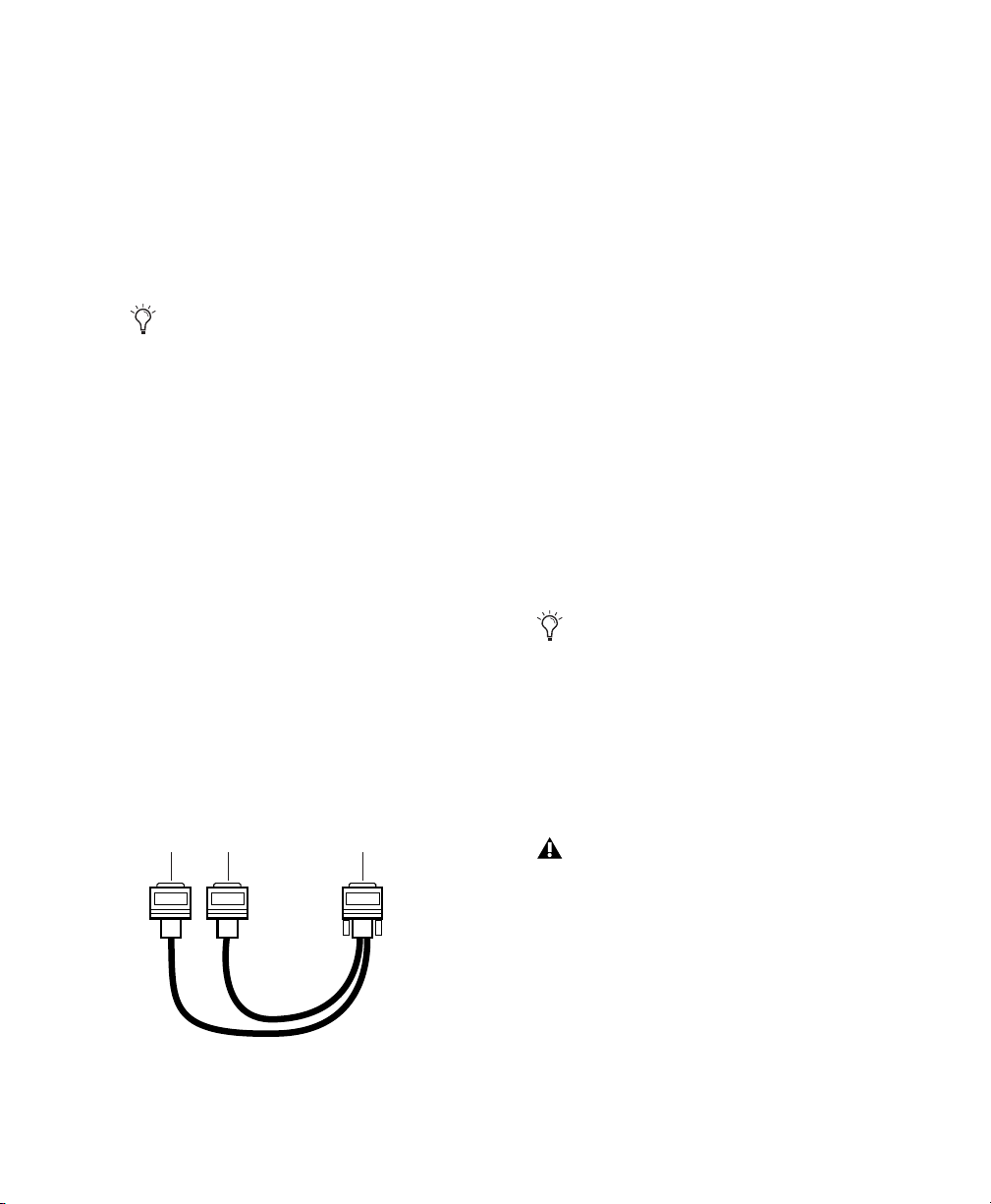
If you are using a Y cable (Legacy 16-channel peripheral cable adapter), connect this to the Legacy port first, then connect the audio interface
peripheral cables to Port A and Port B of the Y
cable.
“A” to first
Legacy I/O
“B” to second
Legacy I/O
To Legacy Por t on
Pro Tools|HD audio interface
If you are using the Y cable to connect multiple
MIX audio interfaces, you must also connect the
Slave Clock Out of the first Legacy interface to
the Slave Clock In of the second Legacy interface with the provided BNC cable. You cannot
clock more than two MIX audio interfaces from
a single Pro Tools|HD audio interface. If you
have a third MIX audio interface, supply its
256x clock from the Pro Tools|HD I/O to which
its 60-pin cable is attached (either your second
audio interface, or directly to an HD Accel or
HD Process card).
To ensure the proper functioning of Legacy
audio interfaces (such as an 888|24 I/O or
882|20 I/O), launch Pro Tools and declare
the Legacy audio interfaces in the Hardware
Setup dialog before turning them on. Then
quit Pro Tools, shut down your computer,
turn on your audio interfaces, and turn on
your computer.
Before you turn on and configure your Legacy audio interfaces, turn down the volume
of output devices. Very loud digital noise
may be emitted before the Legacy audio interface is initialized.
Optional 16-channel peripheral cable adapter
Chapter 2: Windows Installation 25
Page 32

Installing Pro Tools HD Software
After your Pro Tools|HD hardware is installed
and connected, you are ready to install
Pro Tools software.
To install Pro Tools HD software:
1 Start Windows, logging in with Administrator
privileges. For details on Administrator privileges, refer to your Windows documentation.
2 Wait for the Found New Hardware Wizard di-
alog to appear and leave it open: Do not click
Next.
9 Select whether to install the Surround Mixer
plug-in. This plug-in is required for mixing,
mastering, and monitoring in surround.
• Select “Yes – Monitor in Pro Tools Film Format” if your monitoring is configured for
Film Format surround.
• Select “Yes – Monitor in ProControl (DTS
Format)” if you are using a ProControl dedicated controller.
• Select “No – Stereo mixing only” if your
monitoring is configured for Stereo.
AFL/PFL Solo modes require the Surround
Mixer plug-in. See the Pro Tools Reference
Guide for more information.
3 Insert the Pro Tools Installer CD for Windows
in your CD-ROM drive. Locate and open the
Pro Tools Installer folder, and double-click the
Setup icon.
4 Click Next to begin installation.
5 Select the install location. For maximum reli-
ability, install Pro Tools on your startup drive.
Click Next.
6 Select any options you want to install. For
more information, see “Optional Software on
the Pro Tools Installer CD” on page 27.
7 Click Next.
8 Select your work environment. This loads an
initial set of Pro Tools Preferences that include
some of the more popular settings for post production, audio, or audio with MIDI.
Preference settings can be customized at any
time in Pro Tools. See the
ence Guide
for more information.
Pro Tools Refer-
10 Click Next.
11 When installation is complete, click Finish.
Installing QuickTime
QuickTime 6.5 or higher is required for
Pro Tools if you plan to include movie files, or
import MP3 or MP4 (AAC) files in your sessions.
QuickTime for Windows XP is available as a free
download from the Apple Web site.
To install QuickTime:
1 Visit www.apple.com and download the
QuickTime installer application to your computer.
2 Double-click the QuickTime installer applica-
tion and follow the on-screen installation instructions.
3 Restart your computer.
If you turned off Driver Signing Warning on
your computer, be sure to enable it once
Pro Tools hardware and software have been
installed.
Pro Tools|HD Getting Started Guide26
Page 33

Optional Software on the Pro Tools Installer CD
Your Pro Tools Installer CD includes several
software options.
The Digidesign WaveDriver is installed by default when you install Pro Tools.
For detailed information on configuring the
Digidesign WaveDriver, see the
WaveDriver Guide
.
Digidesign
Digidesign ASIO Driver
The Digidesign ASIO (Audio Sound Input Output) Driver is a single-client multichannel
sound driver that allows third-party audio programs that support the ASIO standard to record
and play back through Digidesign hardware.
The Digidesign ASIO Driver is installed by default when you install Pro Tools.
For detailed information on configuring the
Digidesign ASIO Driver, see the
ASIO Guide
To use the Digidesign ASIO Driver without
Pro Tools, you can install the standalone
version of the Digidesign ASIO Driver,
available on the Digidesign Web site
(www.digidesign.com).
.
Digidesign
Digidesign WaveDriver
The Digidesign WaveDriver is a single-client,
multichannel sound driver that allows thirdparty audio programs that support the
WaveDriver MME (Multimedia Extensions)
standard to play back through Digidesign hardware.
To use the Digidesign WaveDriver without
Pro Tools, you can install the standalone
version of the Digidesign WaveDriver,
available on the Digidesign Web site
(www.digidesign.com).
Digidesign Ethernet Software for Control Surface Support
D-Control, D-Command, ProControl or
Control|24 Only
If you plan to use any of these Ethernet-based
control surfaces with your system, you will need
to install the Digidesign Ethernet software.
To install Digidesign Ethernet software:
1 Click Start, right-click My Network Places, and
then choose Properties.
2 Right-click the relevant Local Area Connec-
tion icon, and then choose Properties.
3 Click Install, select Protocol, and click Add.
4 Click Have Disk.
5 Select the DigiNet.inf file (on your Pro Tools
Installer CD, in the Controllers folder), and click
OK.
The Installer installs the DigiNet.inf files in the
Program Files\Common Files\Digidesign\DAE\Controllers folder.
6 Click Close.
Chapter 2: Windows Installation 27
Page 34

Pro Tools Demo Session
The Pro Tools Installer CD-ROM includes a
demo session that you can use to verify that
your system is working.
To install the demo session:
1 Insert the Pro Tools Installer CD into your CD-
ROM drive.
4 Follow the on-screen instructions to install
MacDrive. After installation is complete, restart
your computer.
All formatting and maintenance of HFS+
drives should be carried out when the drives
are connected to a Macintosh. Do not use
the MacDrive utility to initialize or partition Macintosh drives.
2 From your CD-ROM drive, locate the Addi-
tional Files/Pro Tools Demo Session Installer
folder.
3 Double-click Setup.exe.
4 Set the install location to your audio drive and
click Install.
5 When installation is complete, click OK.
MacDrive Demo
The MacDrive utility lets you mount Macintoshbased HFS+ drives on a Windows-based
Pro Tools system and use them as Transfer
drives.
Transfer drives can be used for storage, but
not for playback or recording. To use Macbased audio files on a Windows Pro Tools
system, copy the files from the Mac-based
HFS+ audio drive to a Windows-based
NTFS audio drive.
To install the MacDrive demo included with
Pro Tools:
1 Insert the Pro Tools Installer CD into your CD-
ROM drive.
2 From your CD-ROM drive, locate and open
the Additional Files\MacDrive Demo Installer
folder.
When reformatting an HFS+ drive to NTFS
format, be sure to disable the MacDrive
utility before formatting the drive.
To ensure that files are correctly linked to
sessions when they are transferred from
Windows to Macintosh systems, enable the
“Don’t Remove Extensions” option in
MacDrive Properties.
Removing Pro Tools
If you need to remove Pro Tools software from
your computer, you can use the Add or Remove
Programs command.
To remove Pro Tools from your computer:
1 Choose Start > Control Panel.
2 Launch Add or Remove Programs.
3 From the Currently installed programs list, se-
lect Digidesign Pro Tools.
4 Click the Change/Remove button.
5 Follow the on-screen instructions to remove
Pro Tools.
3 Double-click the MacDrive demo installer.
Pro Tools|HD Getting Started Guide28
Page 35

chapter 3
Macintosh Installation
This chapter contains information for Macintosh systems only. If you are installing Pro Tools
on a Windows computer, see Chapter 2, “Windows Installation.”
Before installing this version of Pro Tools,
refer to the Read Me information included
on the Pro Tools Installer CD.
Installation Overview
Installation of a Pro Tools|HD system on a Macintosh computer includes the following steps:
1 “Macintosh System Optimization” on
page 29.
2 “Installing Pro Tools Hardware” on page 31.
3 “Installing Pro Tools HD Software” on
page 41.
4 “Connecting Audio Interfaces” on page 37.
5 “Launching and Configuring Pro Tools” on
page 43.
6 “Connecting Your Studio” on page 59.
Macintosh System
Optimization
To ensure optimum performance with
Pro Tools, configure your computer before installing Pro Tools hardware and software.
Before configuring your computer, make sure
you are logged in as an Administrator for the account where you want to install Pro Tools. For
details on Administrator privileges in Mac OS X,
refer to your Apple OS X documentation.
Do not use the Mac OS X automatic Software Update feature, as it may upgrade
your system to a version of Mac OS that has
not yet been qualified for Pro Tools.
For details on qualified versions of Mac OS,
refer to the latest compatibility information
on the Digidesign Web site
(www.digidesign.com/compato).
Turning Off Software Update
To turn off the Software Update feature:
1 Choose System Preferences from the Apple
menu and click Software Update.
2 Click Update Software and deselect Check for
Updates.
Chapter 3: Macintosh Installation 29
Page 36

Turning Off Energy Saver
Disabling the Spotlight Shortcuts
To turn off the Energy Saver feature:
1 Choose System Preferences from the Apple
menu and click Energy Saver.
2 Click Sleep and do the following:
• Set the computer sleep setting to Never.
• Set the display sleep setting to Never.
• Deselect “Put the hard disk(s) to sleep
when possible” option.
Setting Processor Performance
(Macintosh G5 Computers Only)
To set the Processor Performance:
1 Choose System Preferences from the Apple
menu and click Energy Saver.
2 Click Options and set Processor Performance
to Highest.
Disabling Spotlight Indexing
The Mac OS X Spotlight feature indexes files and
folders in the background, affecting system performance. It is recommended that you disable
Spotlight indexing before using Pro Tools.
The Mac OS X Spotlight feature uses the same
key commands Pro Tools uses to start recording
(Command+Spacebar), and to record online
(Command+Option+Spacebar). To retain use of
these key commands in Pro Tools, these shortcuts must be disabled.
To disable the Spotlight keyboard shortcut:
1 Choose System Preferences from the Apple
menu and click Spotlight.
2 Deselect “Spotlight menu keyboard shortcut”
and “Spotlight window keyboard shortcut.”
Disabling Dashboard and Exposé
The Mac OS X Dashboard and Exposé features
use function keys that are also used by Pro Tools
(F9-F12). To retain use of these keys in
Pro Tools, these features must be disabled.
To disable Dashboard and Exposé:
1 Choose System Preferences from the Apple
menu and click Dashboard and Exposé.
2 In the pop-up menus for each keyboard short-
cut, set the shortcut to “–” to disable it.
To disable Spotlight indexing:
1 Choose System Preferences from the Apple
menu and click Spotlight.
2 In the Spotlight window, click Privacy.
3 To prevent indexing of a drive, drag its icon
from the desktop into the list.
Pro Tools|HD Getting Started Guide30
Enabling Journaling for Audio Drives
If you plan to use an audio drive that you used
with a previous version of Pro Tools for Macintosh, enable journaling.
To enable journaling:
1 Launch the Disk Utility application, located in
Applications/Utilities.
2 Select the volume in the left column of the
Disk Utility window.
3 Click Enable Journaling in the toolbar.
Page 37
Hard Drive Configuration and
Maintenance
It is recommended that you start with a newly
initialized audio drive.
4 Choose the Mac OS Extended (Journaled) for-
mat.
Do not choose the “Case-Sensitive” format
option. Pro Tools will not operate properly
with case-sensitive formatted drives.
Always back up any important data on
your drive before initializing it, as initializing will erase all data on the drive.
Avoid Recording to the System Drive
Recording to your system drive is not recommended. Recording and playback on a system
drive may result in lower track counts, fewer
plug-ins, or disk errors.
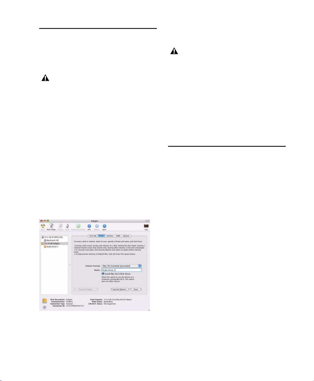
Formatting an Audio Drive
For optimum performance, audio drives should
be formatted as Mac OS Extended (Journaled).
To format an audio drive:
1 Launch the Disk Utility application, located in
Applications/Utilities.
5 Type a name for the new volume.
6 If you plan to connect the drive to a Mac OS 9
computer, select Install Mac OS 9 Drivers.
7 Click Erase.
The drive appears on the Desktop with the new
volume name.
Installing Pro Tools Hardware
To install Pro Tools|HD hardware, you first install Pro Tools|HD cards, then for systems with
more than one card, connect the cards with a
TDM FlexCable.
Installing Pro Tools|HD Cards
This section shows how to install Pro Tools|HD
cards into a Macintosh computer. To install
cards into an expansion chassis, see the Ex-
panded Systems Guide.
To install Pro Tools cards:
1 Turn off your computer and any peripherals.
Leave your computer’s power cable plugged in
so the computer is grounded.
Disk Utility (Mac OS X)
2 Click the Erase tab.
3 Select the drive you want to initialize in the
column on the left side of the window.
2 Disconnect all cables attached to the com-
puter (such as hard drives, displays, USB and
FireWire devices) except for the power cable.
3 Open the computer case.
Chapter 3: Macintosh Installation 31
Page 38

4 Remove the metal access port cover behind
the slot you want to use by removing the screw
and sliding the cover out from the access port.
Before handling any card, discharge static
electricity from your clothes or body by
touching a grounded metal surface, such as
the power supply case inside your computer.
Power Mac G5 (PCI) The PCI-equipped Power
Mac G5 has three PCI slots (named PCI slot 2, 3,
and 4). Slot numbers increase from bottom to top
as you face the open computer case from the
side. Install the HD Core (for PCI) card into PCI
slot 2.
5 Install the Accel Core (for PCIe) or HD Core
(for PCI) card into the lowest-numbered slot in
the computer. This will be the slot closest to the
graphics card, as shown in the following examples:
Power Mac G5 (PCI Express) The PCI Expressequipped Power Mac G5 has three PCI Express
(PCIe) slots (named slots 2, 3, and 4). The PCI
Express slot numbers increase from bottom to top
as you face the open computer case from the
side. Install the Accel Core (for PCIe) card into
PCI slot 2.
PCIe slot 4
PCIe slot 3
PCIe slot 2
AGP slot 1
(video card)
Figure 3. Power Mac G5 (PCI Express equipped)
PCI slot 4
PCI slot 3
PCI slot 2
AGP slot 1
(video card)
Figure 4. Power Mac G5 (PCI equipped)
Power Macintosh “Mirrored Door” G4 The Power
Macintosh “Mirrored Door” G4 has reflective
drive bay doors and four holes across the front.
Its PCI slot numbers increase from left to right as
you face the open computer case from the front.
Note that the PCI slot numbering in the newer
“Mirrored Door” G4 computer runs in the opposite direction of previous G4 models.
Be very careful when opening or closing the
case of a “Mirrored Door” G4 computer.
Any PCI cards installed in the higher-numbered slots may be damaged if they touch
the top of the computer case.
Pro Tools|HD Getting Started Guide32
Page 39

AGP slot 1 (video card)
PCI slot 2
PCI slot 3
PCI slot 4
PCI slot 5
PCI slot 4
PCI slot 3
PCI slot 2
PCI slot 1 (video card)
Power Macintosh “Mirrored Door” Dual Processor G4
Power Macintosh “QuickSilver” G4 The Power
Macintosh “QuickSilver” and earlier G4 models
have a single speaker grille or hole on the front.
Their PCI slot numbers increase from right to left
as you face the open computer case from the
front.
PCI slot 4
PCI slot 3
PCI slot 2
AGP slot 1 (video card)
Power Macintosh “QuickSilver” Dual Processor G4
Power Macintosh Single Processor G4
6 If you are installing additional Pro Tools|HD
cards, skip to the next step. If you have no additional cards to install, do the following:
•Secure the card in place with the screw you
removed earlier.
•Close the computer case.
• Skip to “Connecting Audio Interfaces” on
page 37.
7 Install the first expansion card (if any) in the
second slot (slot 3).
8 Install any remaining expansion cards in the
remaining consecutive slots.
9 If you are installing a SCSI host bus adapter
(HBA) card, install it in the highest-numbered
remaining slot.
Chapter 3: Macintosh Installation 33
Page 40

10 Check to be sure that your cards are installed
in the proper order for your system, starting
with the lowest numeric slot:
Pro Tools|HD (for PCIe) Systems
• Display card for your computer monitor
• Accel Core (for PCIe) card
• HD Accel (for PCIe) cards
• Digidesign-approved video capture card
• SCSI host bus adapter (HBA) card
Pro Tools|HD (for PCI) Systems
• Display card for your computer monitor
• HD Core (for PCI) card
• HD Accel (for PCI) cards
• HD Process (for PCI) cards
• Digidesign-approved video capture card
• SCSI host bus adapter (HBA) card
11 Secure each card in place with the slot access
port screws you removed earlier.
Connecting Pro Tools|HD Cards
In systems that include more than one card, you
must connect all the Pro Tools|HD cards to each
other with TDM FlexCables.
Each Pro Tools|HD card has two ports along the
top of the card, labeled Port A and Port B. The
FlexCable has two connectors, also labeled
Port A and Port B, to ensure proper connection.
Data communication across multiple cards is
achieved by connecting Port B of the first card
to Port A of the next card with a TDM FlexCable.
The first FlexCable always goes from Port B
on the core card to Port A on the first
expansion card, as described in the following steps.
The slot numbering in your computer determines whether you will be working right-to-left
or left-to-right when connecting cards. Refer to
the instructions below for your model of computer.
To connect Pro Tools|HD cards in the Power Mac
G5:
1 Shape the FlexCable before installing it on the
card by holding the cable with its printed side
facing you, and moving the Port B portion of
the cable away from you and outwards, as
shown below. Do not bend the cable more than
you need to, as you may damage the traces in
the cable.
Preparing TDM FlexCable for installation
Pro Tools|HD Getting Started Guide34
Page 41

2 Turn the cable on its side, so that the connec-
tors are facing downwards, and Port A is the
higher side.
Port A
Port B
Orienting the FlexCable
3 Slide the FlexCable into the notch of the sec-
ond card, so that the Port B connector of the
FlexCable can be aligned with Port B of the first
card; and the Port A connector of the FlexCable
can be aligned with Port A of the second card, as
shown below.
Port A connector
Port B
connector
Expansion
card
Core card
5 Verify the connection. Make sure the FlexCa-
ble ports seat flat against the sockets on the
cards, and are firmly attached.
6 For systems with more than two cards, con-
nect each additional card to its preceding card.
Use FlexCables to connect card pairs together, as
described above, until all cards are connected.
(Each expansion card is packaged with a FlexCable.)
7 Close the computer case.
8 Proceed to “Connecting Audio Interfaces” on
page 37.
To connect Pro Tools|HD cards in the Power
Macintosh “Mirrored Door” G4:
1 Shape the FlexCable before installing it on the
card by holding the cable with its printed side
facing you, and moving the Port B portion of
the cable straight towards you and inwards, as
shown below. Do not bend the cable more than
you need to, as you may damage the traces in
the cable.
Inserting TDM FlexCable
4 Connect the Port A connector of the FlexCa-
ble to Port A on the second card. Push gently but
firmly until the cable is fully connected to the
card. Attach the other end of the FlexCable (labeled Port B) to Port B on the first card.
Expansion card in PCI slot 3
Port B Port A
Port B
Port B
Core card in PCI slot 2
Port A
Port APort B
Port A
Top view of two cards connected with TDM FlexCable
Preparing TDM FlexCable for installation
Chapter 3: Macintosh Installation 35
Page 42

2 Slide the FlexCable into the notch of the first
card, so that the Port B connector of the FlexCable can be aligned with Port B of the first card;
and the Port A connector of the FlexCable can
be aligned with Port A of the second card, as
shown below.
Expansion card
To connect Pro Tools|HD cards in Power
Macintosh “QuickSilver” and earlier G4
computers:
1 Shape the FlexCable before installing it on the
card by holding the cable with its printed side
facing you, and moving the Port A portion of
the cable straight towards you and inwards, as
shown below. Do not bend the cable more than
you need to, as you may damage the traces in
the cable.
PORT B
PORT A PORT B
PORT A
Inserting TDM FlexCable
3 Connect the Port A connector of the FlexCa-
ble to Port A on the second card. Push gently but
firmly until the cable is fully connected to the
card. Attach the other end of the FlexCable (labeled Port B) to Port B on the first card.
Expansion card
Core card
Top view of two cards connected with TDM FlexCable
4 Verify the connection. Make sure the FlexCa-
ble ports seat flat against the sockets on the
cards, and are firmly attached.
5 For systems with more than two cards, con-
nect each additional card to its preceding card.
Use FlexCables to connect card pairs together, as
described above, until all cards are connected.
(Each expansion card is packaged with a FlexCable.)
6 Close the computer case.
Preparing TDM FlexCable for installation
2 Slide the FlexCable into the notch of the sec-
ond card, so that the Port B connector of the
FlexCable can be aligned with Port B of the first
card; and the Port A connector of the FlexCable
can be aligned with Port A of the second card, as
shown below.
PORT A
PORT B
PORT B
PORT A
Expansion card
PORT B
PORT B
PORT A
PORT A
Inserting TDM FlexCable
7 Proceed to “Connecting Audio Interfaces” on
page 37.
Pro Tools|HD Getting Started Guide36
Page 43
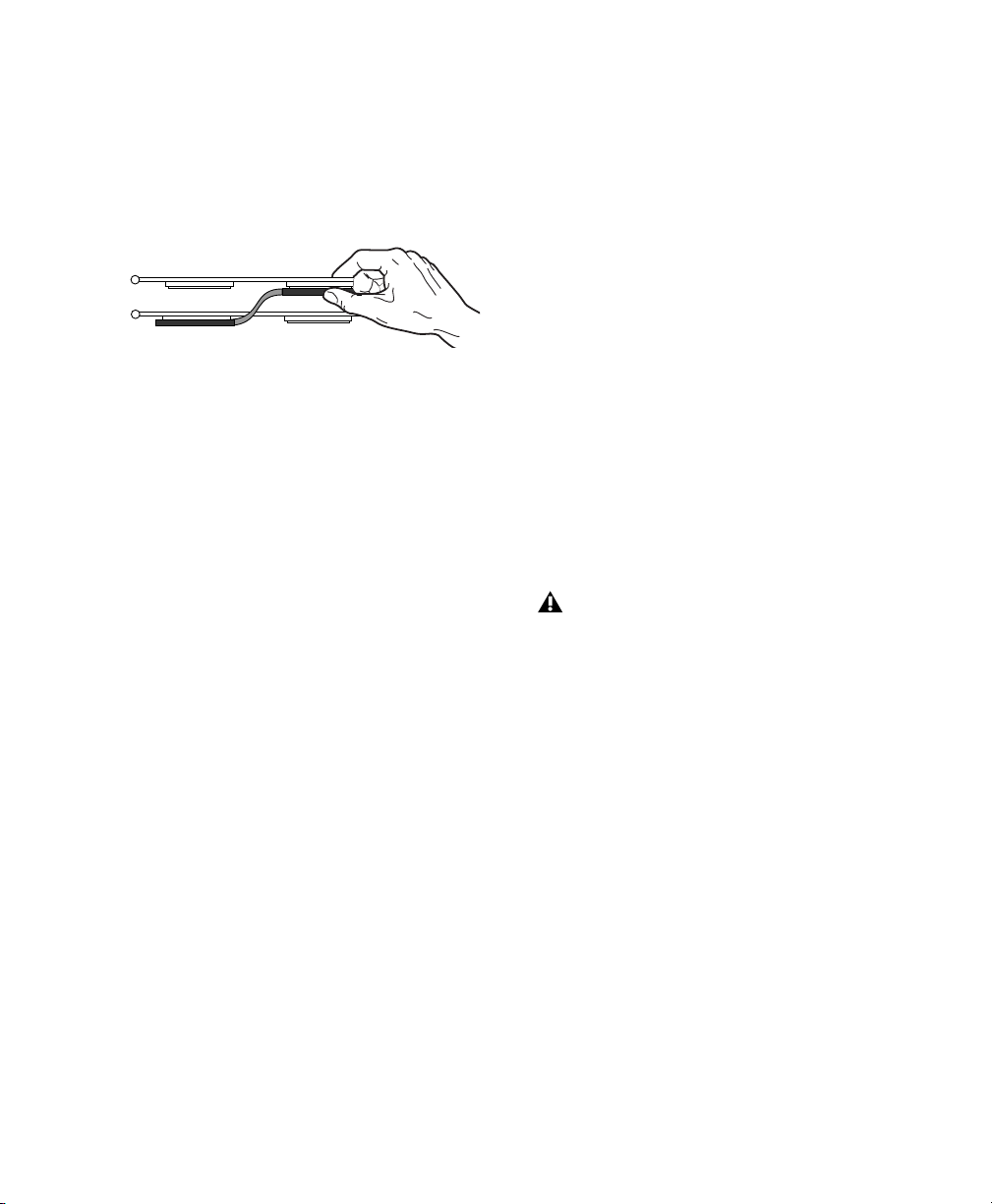
3 Connect the Port A connector of the FlexCa-
ble to Port A on the second card. Push down
gently but firmly until the cable is fully connected to the card. Next, attach the other end of
the FlexCable (labeled Port B) to Port B on the
first card.
PORT A
PORT A
Top view of two cards connected with TDM FlexCable
4 Verify the connection. Make sure the FlexCa-
PORT B
PORT B
ble ports seat flat against the sockets on the
cards, and are firmly attached.
5 For systems with more than two cards, con-
nect each additional card to its preceding card.
Use FlexCables to connect card pairs together, as
described above, until all cards are connected.
(Each expansion card is packaged with a FlexCable.)
6 Close the computer case.
7 Proceed to “Connecting Audio Interfaces” on
page 37.
Connecting Audio Interfaces
Each Pro Tools|HD audio interface (except the
96i I/O) supplies up to 16 channels of input and
output to your system. Audio interfaces are connected directly to Pro Tools|HD cards, or
through the Expansion ports on other
Pro Tools|HD interfaces.
Each Pro Tools|HD card supports up to 32 channels. To get a full 32 channels of I/O from one
card, you can connect, or daisy-chain, a second
16-channel Pro Tools|HD I/O to the first 16channel Pro Tools|HD I/O that is connected directly to the Pro Tools|HD card.
Pro Tools|HD supports up to a maximum of ten
192 I/Os, 192 Digital I/Os, or 96 I/Os. Up to five
96i I/Os can be used simultaneously.
For examples of connecting multiple I/Os, see
Figure 5 and Figure 6 on page 39.
Pro Tools|HD audio interfaces need room at
their sides to maintain proper air flow for
cooling. Do not block the sides of the unit or
disconnect the internal fan. If the units are
rack-mounted in a case, remove the case
lids or doors before operating the system.
Failure to do so can result in the units overheating very quickly, which can permanently damage sensitive components.
Legacy audio interfaces can also be connected to
Pro Tools|HD interfaces. See “Connecting an
Additional 16 Channels of Audio with Legacy
Audio Interfaces” on page 40.
Chapter 3: Macintosh Installation 37
Page 44

To connect Pro Tools|HD audio interfaces:
1 If you are using a single 192 I/O,
192 Digital I/O, 96 I/O, or 96i I/O, connect its
Primary Port to the HD Core For PCI) or Accel
Care (for PCIe) card with the DigiLink cable provided with the HD Core (for PCI) or Accel Core
(for PCIe) card. You must attach at least one
192 I/O, 192 Digital I/O, 96 I/O, or 96i I/O to
your system in order for Pro Tools to launch.
If you have at least one 192 I/O or
192 Digital I/O in your system configuration, it must be connected to the HD Core
(for PCI) or Accel core (for PCIe) card as the
primary interface.
Connecting Loop Sync
If you are using two or more Pro Tools|HD audio
interfaces or a SYNC I/O peripheral, Loop Sync
must be connected to maintain proper clock
among the devices.
To make Loop Sync connections:
1 Connect the Loop Sync Out of each interface
to the Loop Sync In of the next interface with
the BNC cables included in your I/O packaging.
2 Connect the Loop Sync Out of the last inter-
face to the Loop Sync In of the primary interface
or SYNC I/O peripheral.
2 Connect additional Pro Tools|HD audio inter-
faces to subsequent Digidesign audio cards, or
daisy-chain the interfaces (by connecting the
Primary Port of the secondary interface to the
Expansion Port of the primary interface).
If you are connecting both 192 I/O (or
192 Digital I/O) and 96 I/O audio interfaces to
your system, connect the 192 I/O (or
192 Digital I/O) to your HD Core (for PCI) or Accel Core (for PCIe) card, followed by any additional 192 I/O (or 192 Digital I/O) interfaces
connected to subsequent cards. Then connect
96 I/O interfaces to subsequent cards, or to
other interfaces, then connect 96i I/O interfaces.
You can also connect a single Pro Tools|HD interface to each Pro Tools|HD card in your system
using the provided DigiLink cables. (However,
there is no advantage to this configuration over
daisy-chaining interfaces.)
Connecting Legacy Audio Interfaces
If you are connecting a Digidesign Legacy audio
interface, continue with “Connecting an Additional 16 Channels of Audio with Legacy Audio
Interfaces” on page 40. (The 96i I/O does not
support Legacy I/O.)
Pro Tools|HD Getting Started Guide38
Page 45

12-foot DigiLink cable
HD Core or
Accel Core card
18-inch DigiLink cable
Figure 5. Two 96 I/Os (32-channel system)
18-inch DigiLink cable
Loop Sync cables
Loop Sync cables
12-foot DigiLink cable
Loop Sync cables
HD Core or
Accel Core card
TDM FlexCable
12-foot DigiLink cable
Figure 6. Three 96 I/Os (48-channel system)
HD Accel card
or HD Process card
Chapter 3: Macintosh Installation 39
Page 46

Connecting an Additional 16 Channels of Audio with Legacy Audio Interfaces
Each 192 I/O, 192 Digital I/O, and 96 I/O can
support 16 channels of audio to and from
Digidesign Legacy I/Os. (The 96i I/O does not
support Legacy I/O.) Legacy I/Os include the
888|24 I/O, 882|20 I/O, 1622 I/O, and the 24-bit
ADAT Bridge I/O.
3 To properly clock the Legacy audio interface,
connect the Ext. Clock output port on the
Pro Tools|HD I/O to the Slave Clock IN on the
Legacy audio interface. The Legacy audio interface will switch to Slave mode once the proper
clock is outputting from the Pro Tools|HD I/O.
Always use the Ext. Clock Out port of the same
I/O to which the Legacy audio interface is attached.
The original 888 I/O and 882 I/O interfaces
are not supported with Pro Tools|HD.
To connect Digidesign Legacy audio interfaces:
1 Connect the “MIX card” end of the peripheral
cable that came with your Legacy audio interface (60-pin side) to the Legacy Port on the primary Pro Tools|HD audio interface. Connect the
other end to the Computer Port on the Legacy
audio interface.
2 Connect any additional Legacy audio inter-
faces in the same manner, to Pro Tools|HD audio
interfaces connected directly to Pro Tools|HD
cards.
– or –
If you are using a Y cable (Legacy 16-channel peripheral cable adapter), connect this to the Legacy port first, then connect the audio interface
peripheral cables to Port A and Port B of the Y
cable.
“A” to first
Legacy I/O
“B” to second
Legacy I/O
To Legacy Por t on
Pro Tools|HD audio interface
If you are using the Y cable to connect multiple
MIX audio interfaces, you must also connect the
Slave Clock Out of the first Legacy interface to
the Slave Clock In of the second Legacy interface with the provided BNC cable. You cannot
clock more than two MIX audio interfaces from
a single Pro Tools|HD audio interface. If you
have a third MIX audio interface, supply its
256x clock from the Pro Tools|HD I/O to which
its 60-pin cable is attached (either your second
audio interface, or directly to an HD Accel or
HD Process card).
To ensure the proper functioning of Legacy
audio interfaces (such as an 888|24 I/O or
882|20 I/O), launch Pro Tools and declare
the Legacy audio interfaces in the Hardware
Setup dialog before turning them on. Then
quit Pro Tools, shut down your computer,
turn on your audio interfaces, and turn on
your computer.
Before you turn on and configure your Legacy audio interfaces, turn down the volume
of output devices. Very loud digital noise
may be emitted before the Legacy audio interface is initialized.
Optional 16-channel peripheral cable adapter
Pro Tools|HD Getting Started Guide40
Page 47

Installing Pro Tools HD Software
After your Pro Tools|HD hardware is installed
and connected, you are ready to install
Pro Tools software.
Do not install or operate Pro Tools while
logged in as a root-level user. File permissions of a root-level user make it possible to
perform actions that may conflict with
Pro Tools file management tasks.
To install Pro Tools HD software:
1 Make sure you are logged in as an Administra-
tor for the account where you want to install
Pro Tools. For details on Administrator privileges in Mac OS X, refer to your Apple OS X documentation.
2 Insert the Pro Tools Installer CD in your CD-
ROM drive. Double-click “Install Pro Tools.”
3 Enter your Administrator password and click
OK to authenticate the installation.
4 Follow the on-screen instructions to continue
and accept installation.
5 In the Installer window, make sure the Install
Location is on your Startup drive.
6 In the Installer window, choose Custom In-
stall from the pop-up menu, and click Install.
9 Select your work environment. This loads an
initial set of Pro Tools Preferences that include
some of the more popular settings for post production, audio, or audio with MIDI.
Preference settings can be customized at any
time in Pro Tools. See the Pro Tools Reference Guide for more information.
10 Select whether to install the Surround Mixer
plug-in. This plug-in is required for mixing,
mastering, and monitoring in surround:
• Select “Yes – Monitoring in Standard
Pro Tools (Film Format)” if your monitoring is configured for Film Format surround.
• Select “Yes – Monitoring in ProControl
(DTS Format)” if you are using a ProControl dedicated controller.
• Select “No – Stereo mixing only” if your
monitoring is configured for Stereo.
AFL/PFL Solo modes require the Surround
Mixer plug-in. See the Pro Tools Reference
Guide for more information.
11 Click Continue.
12 When installation is complete, click Restart.
– or –
Click Continue to install any additional software or documentation, and restart your computer when you are finished.
7 Select the Pro Tools Installer. You can also se-
lect from a list of optional items to install along
with Pro Tools. Click the information button
next to each item for a description of its contents.
8 Click Install.
Chapter 3: Macintosh Installation 41
Page 48

Digidesign CoreAudio Driver
The Digidesign CoreAudio Driver is a multi-client, multichannel sound driver that allows
CoreAudio compatible applications to record
and play back through Digidesign hardware.
The CoreAudio Driver is installed by default
when you install Pro Tools.
For detailed information on configuring the
Digidesign CoreAudio Driver, see the
design CoreAudio Guide
.
Digi-
Optional Software on the Pro Tools Installer CD
Your Pro Tools Installer CD includes separate installers for the following optional items.
Standalone CoreAudio Driver
2 Set the install location to your audio drive,
and click Install.
3 When installation is complete, click Quit.
Removing Pro Tools
If you need to remove Pro Tools software from
your computer, you can use the Installer CD or
the downloaded Installer file.
To remove Pro Tools from your computer:
1 Make sure you are logged in as an Administra-
tor for the account where Pro Tools is installed.
For details on Administrator privileges in
Mac OS X, refer to your Apple OS X documentation.
2 Insert the Pro Tools Installer CD in your CD-
ROM drive or locate the downloaded Installer
file.
The Digidesign CoreAudio Driver can be installed as a standalone driver on Macintosh systems that do not have Pro Tools installed.
For detailed information on installing and
configuring CoreAudio Driver, see the
CoreAudio Usage Guide.
Pro Tools Demo Session
The Pro Tools Installer CD includes a demo session that you can use to verify that your system
is working.
To install the demo session:
1 Insert the Pro Tools Installer CD in your CD-
ROM drive. Locate and double-click the demo
session installer icon.
Pro Tools|HD Getting Started Guide42
3 Double-click “Install Pro Tools.”
4 Enter your Administrator password and click
OK.
5 In the Installer window, choose Uninstall
from the pop-up menu, and click Uninstall.
6 Follow the on-screen instructions to remove
Pro Tools.
7 When finished, click Quit to close the Installer
window.
Page 49

chapter 4
Launching and Configuring Pro Tools
Checking the System
Before you launch Pro Tools, you may want to
run the DigiTest diagnostic application to ensure that all Pro Tools|HD cards in the system
are recognized, installed in the proper order,
and have valid TDM FlexCable connections.
Starting Up Your System
Whenever you start your system, turn on all of
your system components in a specific order.
To start your Pro Tools system:
1 Make sure all your equipment (including your
computer) is off.
2 For Pro Tools|HD systems with an expansion
chassis, turn on the expansion chassis.
3 Turn on any external hard drives. Wait ap-
proximately ten seconds for them to spin up to
speed.
4 Turn on any MIDI interfaces and devices, or
synchronization peripherals.
Running DigiTest
DigiTest is installed with Pro Tools and resides
in the following folder on your hard drive:
Digidesign/Pro Tools/Pro Tools Utilities.
Before you run DigiTest, lower the volume
of all output devices. Very loud digital noise
may be emitted during the test.
To run DigiTest:
1 Quit Pro Tools if it is running.
2 Lower the volume of all output devices on
your system.
3 Locate and double-click the DigiTest icon on
your hard drive.
DigiTest opens and lists the supported cards it
finds in your system, showing their corresponding slot locations.
5 Lower the volume of all output devices, then
turn on your Pro Tools audio interfaces. Wait at
least fifteen seconds for the audio interface to
initialize and the status LEDs to stop flashing.
6 Turn on your computer.
Chapter 4: Launching and Configuring Pro Tools 43
Page 50

If you have a large number of cards or audio interfaces, it may take a while for the DigiTest window to appear, as DigiTest scans for all cards and
interfaces connected to the system.
6 When prompted, power cycle all Pro Tools pe-
ripherals in your system. Click Continue.
7 To test the interfaces connected to your sys-
tem, check “Test I/O Box.”
LEDs on your digital interfaces may light up
during this test. This is normal.
8 When the test is finished, you can view the
test results by doing one of the following:
• Click the Get Results button next to a card
name.
• Click the Results tab and choose a card slot
from the pop-up menu.
9 In the Results page of the DigiTest window,
click Show Failures Only to display failed tests
for the selected card, or click Show All Results to
display all test results for the selected card.
DigiTest main test window
The order in which cards are listed within
DigiTest may not match the actual slot locations of cards installed in your computer or
expansion chassis. This is normal, and does
not affect DigiTest operations in any way.
4 Select the cards in your system you want to
test by selecting Test in the left hand column for
each card.
5 Click Run.
If cards are not installed in the proper order,
DigiTest will display error codes in the Status
box of each card identified as being misconfigured.
The more cards and audio interfaces in your system, the longer the test will take.
For descriptions of error codes, refer to
Appendix B, “DigiTest Error Codes.”
10 Click Quit to close DigiTest.
11 Restart your computer.
Pro Tools|HD Getting Started Guide44
Page 51

Errors and Undetected Cards
Complete the steps below if any of the following
occur:
■ DigiTest fails to launch.
■ An error message has been displayed for a card
in DigiTest.
■ A supported card is installed but not automat-
ically detected during DigiTest.
Identifying Digidesign Cards with DigiTest
You can use DigiTest to identify which cards are
in which slots in your system. This is especially
useful if you have multiple Digidesign cards of
the same type installed in your system.
To identify Digidesign cards with DigiTest
1 Quit Pro Tools if it is running.
If a supported card is installed and is not
automatically detected:
1 Quit DigiTest.
2 Turn off the entire Pro Tools system.
3 Reinstall the Pro Tools|HD cards.
4 Check the card seating.
5 Check the TDM FlexCable connections.
Check the orientation of the cable from card to
card (ports B to A), and check the integrity of the
FlexCable connections to the cards.
6 Turn on the system.
7 Run DigiTest again.
2 Locate and double-click the DigiTest icon on
your hard drive.
DigiTest opens and lists the supported cards it
finds in your system.
3 Open your computer case or expansion chas-
sis so you can see the top edge of the cards installed in your system.
4 In the DigiTest window, select the ID check
box next to a card name. The green LED near the
top edge of the corresponding card flashes.
Viewing Card Information with DigiTest
DigiTest can display identifying information
such as serial number, date of manufacture, and
firmware ROM version for each card in your system. This information is useful if you need to
contact Digidesign Technical Support about
your Pro Tools hardware.
To display information for a card in your system:
1 Quit Pro Tools if it is running.
2 Locate and double-click the DigiTest icon on
your hard drive.
3 Click the Slot Info tab.
4 Choose a card slot from the pop-up menu.
Chapter 4: Launching and Configuring Pro Tools 45
Page 52

Updating Audio Peripheral Firmware with DigiTest
If firmware updates are available for any of your
Pro Tools|HD audio interfaces (192 I/O,
192 Digital I/O, 96 I/O, or 96i I/O), you can use
DigiTest to perform the update. Within DigiTest, the Firmware Update page tells you the firmware version for the selected peripheral and lets
you update to a newer version, if necessary.
To update the firmware in a Pro Tools|HD audio
interface:
1 Quit Pro Tools if it is running.
2 Locate and double-click the DigiTest applica-
tion on your hard drive.
3 Click the Firmware tab.
4 Choose a card slot from the pop-up menu. If
any Pro Tools|HD audio interfaces are connected to the card, the Primary or Secondary options will become available in the HD Peripheral
section of the Firmware page.
If any connected interfaces are not recognized,
check the connections and power to each interface and click Re-Scan.
5 Under HD Peripheral, select Primary or Sec-
ondary to view the firmware version for the corresponding interface. The firmware version is
displayed just below the HD Peripheral section
of the Firmware page.
6 If the firmware version is not current, click Be-
gin Update to update the firmware in the selected audio interface.
The status of the firmware update process is displayed in the status area at the bottom of the
Firmware page.
Launching Pro Tools
To use Pro Tools HD, you must always have an
inserted iLok with an authorization for
Pro Tools HD. One pre-authorized iLok is included with the Pro Tools HD software.
To authorize Pro Tools HD software:
1 Insert the pre-authorized iLok into an avail-
able USB port on your computer.
2 Do one of the following:
• Double-click the Pro Tools HD shortcut on
the desktop (Windows) or click the
Pro Tools HD icon in the Dock (Macintosh).
– or –
• Locate and double-click the Pro Tools HD
application on your hard drive.
Do not remove the iLok during Pro Tools
launch or use.
Configuring Pro Tools
Pro Tools System Settings
Pro Tools lets you adjust the performance of
your system by changing system settings that affect its capacity for processing, playback, and recording.
In most cases, the default settings for your system provide optimum performance, but you
may want to adjust them to accommodate large
or processing-intensive Pro Tools sessions.
7 After the update process is complete, click
Quit to close DigiTest.
Pro Tools|HD Getting Started Guide46
Page 53

Hardware Buffer Size
RTAS Processors
The Hardware Buffer Size (H/W Buffer Size) controls the size of the buffer used to handle host
processing tasks such as Real-Time AudioSuite
(RTAS) plug-ins. The H/W Buffer setting can also
be used to manage monitoring latency.
• Lower Hardware Buffer Size settings reduce
monitoring latency, and are useful when you are
recording live input.
• Higher Hardware Buffer Size settings allow for
more audio processing and effects, and are useful when you are mixing and using more RTAS
plug-ins.
In addition to causing slower screen response and monitoring latency, higher
Hardware Buffer Size settings can increase
the latency caused by RTAS plug-ins, and
affect the accuracy of plug-in automation,
mute data, and MIDI track timing.
To change the Hardware Buffer Size:
1 Choose Setup > Playback Engine.
The RTAS Processors setting determines the
number of processors in your computer allocated for RTAS plug-in processing.
With computers that have multiple processors,
or that feature multi-core processing or hyperthreading, this setting lets you enable multi-processor support for RTAS processes. Used in combination with the CPU Usage Limit setting, the
RTAS Processors setting lets you control the way
RTAS processing and other Pro Tools tasks are
carried out by the system.
◆ A higher number of processors reserves more
CPU processing capacity for RTAS plug-in processing. This is useful for sessions with large
number of RTAS plug-ins.
◆ A lower number of processors leaves more
CPU processing capacity for automation, screen
redraws, and video playback in Pro Tools, or for
other application running at the same time as
Pro Tools.
To set the number of RTAS Processors:
1 Choose Setup > Playback Engine.
Playback Engine dialog for Pro Tools|HD system
2 From the H/W Buffer Size pop-up menu, select
the audio buffer size, in samples.
3 Click OK.
2 From the RTAS Processors pop-up menu, select
the number of available processors you want to
allocate for RTAS plug-in processing.
3 Click OK.
Chapter 4: Launching and Configuring Pro Tools 47
Page 54

CPU Usage Limit
Number of Voices
The CPU Usage Limit controls the percentage of
CPU resources allocated to Pro Tools host processing tasks. Used in combination with the
RTAS Processors setting, the CPU Usage Limit
setting lets you control the way Pro Tools tasks
are carried out by the system.
◆ Lower CPU Usage Limit settings limit the ef-
fect of Pro Tools processing on other CPU-intensive tasks, such as screen redraws, and are useful
when you are experiencing slow system response, or when running other applications at
the same time as Pro Tools.
◆ Higher CPU Usage Limit settings allocate
more processing power to Pro Tools, and are
useful for playing back large sessions or using
more real-time plug-ins.
The maximum available CPU Usage Limit depends on the number of processors in your computer and on the number of processors you
specify for RTAS processing. This value can
range from 85 percent for single-processor computers to 99 percent for multi-processor computers.
The Number of Voices setting lets you control
the number of voices available on your system.
For example, the default number of voices on an
Pro Tools|HD 1 system is 48 voices, using one
DSP (at sample rates of 44.1 kHz or 48 kHz).
Changing the number of voices affects
DSP usage, the total number of voiceable
tracks, and overall system performance.
Depending on the current sample rate and the
number of cards in your system, and whether
you are using an expansion chassis, you will
have different choices for voice count.
For additional information on voice count,
refer to the Pro Tools Reference Guide and
the Expanded Systems Guide.
To change the Number of Voices and DSP to
allocate for voicing:
1 Choose Setup > Playback Engine.
Increasing the CPU Usage Limit may slow
down screen responses on slower computers.
To change the CPU Usage Limit:
1 Choose Setup > Playback Engine.
2 From the CPU Usage Limit pop-up menu, se-
lect the percentage of CPU processing you want
to allocate to Pro Tools.
3 Click OK.
Pro Tools|HD Getting Started Guide48
Page 55

2 Select the number of voices and DSPs to allo-
cate for voicing by choosing a value from the
Number of Voices pop-up menu.
• Select higher voice numbers when your
Digidesign cards are the only PCI cards in
your computer, or when you are using an
expansion chassis to run higher track
counts (such as 64 tracks at 96 kHz) and
you want more voices per DSP (such as 16
voices per DSP at 96 kHz). These settings
use fewer DSP chips for mixing (leaving
more available for plug-ins) but place the
highest processing load on each.
• Select medium voice numbers when your
Digidesign cards are in an expansion chassis, or when you are using other PCI cards
along with Digidesign cards. These settings
generally provide an optimum balance between number of chips needed for voicing,
and the processing load placed on each.
• Select minimum voice numbers if you are
using high-bandwidth PCI cards (such as
video capture cards) along with your
Digidesign cards. These settings place the
lightest processing load on each allocated
DSP chip, but generally require more DSP
chips be dedicated to voicing and mixing
(leaving fewer available for plug-ins).
Default Sample Rate
The Sample Rate setting appears as the default
sample rate when you create a new session.
(This setting is available only when there is no
session open.)
You can change the sample rate when creating a new Pro Tools session by selecting a
different sample rate in the New Session dialog. (See
“Starting a Session” on page 67.)
To change the default Sample Rate:
1 Choose Setup > Playback Engine.
2 Select the sample rate from the Sample Rate
pop-up menu.
3 Click OK.
Delay Compensation Engine
Delay Compensation automatically manages
DSP delays that occur on audio tracks, Auxiliary
Inputs, or Master Faders because of plug-in use
and mixer routing. With Delay Compensation
enabled, Pro Tools maintains time-alignment
between tracks that have plug-ins with differing
DSP delays, tracks with different mixing paths,
tracks that are split off and recombined within
the mixer, and tracks with hardware inserts.
Number of Voices menu (HD Accel-equipped system)
3 Click OK.
To maintain time alignment, Pro Tools adds the
exact amount of delay to each track necessary to
make that particular track’s delay equal to the
delay of the track that has the longest delay.
Delay Compensation should be enabled during
mixing and playback for optimal delay compensated sound. In some cases when recording, Delay Compensation should be turned off.
For more information on using Delay Compensation, see the Pro Tools Reference
Guide.
Chapter 4: Launching and Configuring Pro Tools 49
Page 56

Delay Compensation Settings
DAE Playback Buffer Size
There are three settings in the Playback Engine
dialog for dedicating DSP resources for Delay
Compensation:
None Allocates no DSP resources for Delay Compensation.
Short Allocates minimal DSP resources of delay
compensation for each channel. This is the
most efficient setting for Pro Tools|HD Accel
systems.
Long Allocates maximum DSP resources for Delay Compensation for each mixer channel. Long
Delay Compensation uses the same DSP resources used by high DSP overhead plug-ins.
To configure the Delay Compensation Engine:
1 Choose Setup > Playback Engine.
2 From the Delay Compensation Engine pop-up
menu, select a Delay compensation setting.
3 Click OK.
The Delay Compensation setting is saved as a
session and system preference.
To enable Delay Compensation:
■ Choose Options > Delay Compensation.
The DAE Playback Buffer Size determines the
amount of memory DAE allocates for disk buffers. The optimum DAE Playback Buffer Size for
most disk operations is Level 2.
◆ DAE Playback Buffer Size settings lower than
Level 2 may improve playback and recording
initiation speed, but may make it difficult to
play or record tracks reliably with sessions containing a large number of tracks or a high density of edits, or with systems that have slower or
heavily fragmented hard drives.
◆ DAE Playback Buffer Size settings higher than
Level 2 will allow for a higher density of edits in
a session or a higher track count when using
slower hard drives. However, a higher setting
can also cause a time lag to occur when starting
playback or recording, or longer audible time lag
while editing during playback.
Using a larger DAE Playback Buffer Size
leaves less system memory for other tasks.
The default setting of Level 2 is recommended unless you are encountering -9073
(“Disk too slow or fragmented”) errors.
To change the DAE Playback Buffer Size:
1 Choose Setup > Playback Engine.
Pro Tools|HD Getting Started Guide50
Page 57
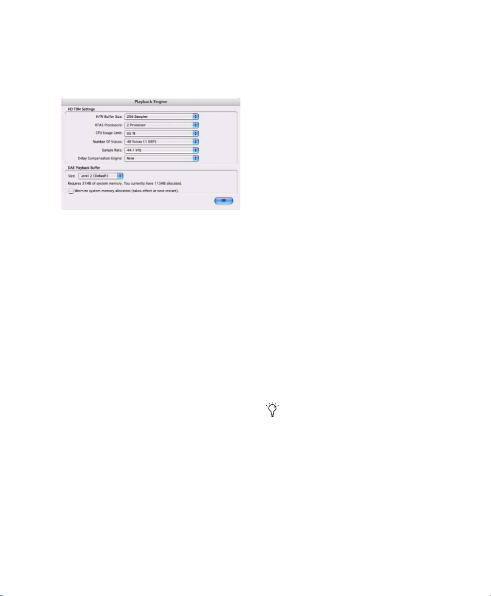
2 From the DAE Playback Buffer pop-up menu,
select a buffer size. Memory requirements for
each setting are shown at the bottom of the
Playback Engine dialog.
Playback Engine dialog for Pro Tools|HD Accel system
3 Click OK.
MIDI Studio Setup
(Windows Only)
If you plan to use any MIDI devices with
Pro Tools, configure your MIDI setup with MIDI
Studio Setup. See Appendix C, “Configuring
MIDI Studio Setup (Windows Only).”
Audio MIDI Setup (AMS)
(Macintosh Only)
If you plan to use any MIDI devices with
Pro Tools, configure your MIDI setup with the
Apple Audio MIDI Setup (AMS) utility. See
Appendix D, “Configuring AMS
(Mac OS X Only).”
If Pro Tools needs more system memory for the
DAE Playback Buffer, it will prompt you to restart your computer.
System Memory Allocation
When you start your computer, Pro Tools automatically reserves a portion of system memory
for the DAE Playback Buffer. This reserved memory is unavailable to other applications, even if
Pro Tools is not running.
You can set Pro Tools to reserve only the minimum amount of required memory, so that more
system memory is available to other applications.
To minimize system memor y allocation:
1 Choose Setup > Playback Engine.
2 Select the “Minimize System Memory Alloca-
tion” option.
3 Click OK.
4 Restart your computer.
Pro Tools Hardware Settings
Pro Tools lets you set the default sample rate
and clock source for your system, as well as a
range of controls specific to each type of audio
interface.)
Default Sample Rate
The Sample Rate setting appears as the default
sample rate when you create a new session.
(This setting is available in the Hardware Setup
dialog only when no session is open.)
You can change the sample rate when creating a new Pro Tools session by selecting a
different sample rate in the New Session dialog. (See
“Starting a Session” on page 67.)
Chapter 4: Launching and Configuring Pro Tools 51
Page 58
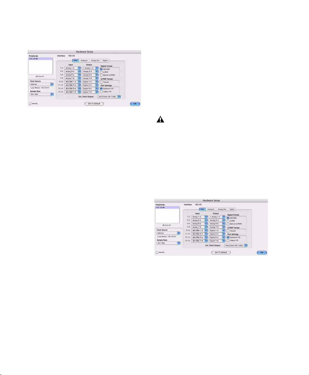
To change the default Sample Rate:
1 Choose Setup > Hardware.
Hardware Setup dialog for 192 I/O, Main page
2 Choose the sample rate from the Sample Rate
pop-up menu.
3 Click OK.
[Encl], S/PDIF, Optical [Encl], AES/EBU 1–8,
TDIF, ADAT, and Word Clock. For details, refer
to the Pro Tools Reference Guide or the guide for
your audio interface.
To select the Clock Source:
1 Choose Setup > Hardware.
2 Choose the clock source from the Clock
Source pop-up menu.
3 Click OK.
Your digital input device must be connected
and powered on for Pro Tools to synchronize to it. If your input device is not powered
on, leave the Clock Source set to Internal.
High Sample Rates and Expanded Systems
With 176.4 kHz and 192 kHz sample rates, as
many as four Pro Tools|HD cards can be used.
Any additional cards (up the total system maximum of seven cards) will switch to Inactive
mode. The cards and any attached peripherals
will become active again when the sample rate is
set to 96 kHz or lower. See the Pro Tools Expanded Systems Guide for more information.
Clock Source
The Pro Tools Hardware Setup dialog lets you select the Clock Source for the system.
Internal If you are recording an analog signal directly into Pro Tools, you will usually use the
Pro Tools Internal clock source.
External If you are transferring material into
Pro Tools from an external digital device, or if
you utilize a common house clock signal, you
will synchronize Pro Tools to that digital device
or common signal. Depending on your audio interface, external options can include AES/EBU
Configuring Audio Interfaces
Pro Tools|HD audio interfaces support 16 channels of simultaneous I/O and multiple I/O formats (including analog, AES/EBU, ADAT Optical, S/PDIF, and TDIF).
Hardware Setup dialog for 192 I/O, Main page
The Main page of the Hardware Setup dialog is
where you define which physical inputs and
outputs on your audio interface are routed to
available inputs and outputs in Pro Tools. You
can think of this window as a patchbay that allows you to route any of the inputs or outputs
on your Pro Tools|HD audio interfaces to channel assignments in the Pro Tools mixer.
Pro Tools|HD Getting Started Guide52
Page 59

The Main page also provides controls for defining whether Expansion Port or Legacy Port peripherals are active.
To configure the interfaces in your system, you
select each interface in the Peripherals list and
set the parameters for that interface.
Identifying Audio Interfaces
If you have multiple audio interfaces of the
same type connected to your system, before you
make audio connections to them, you should
confirm the identity of each interface. This ensures that you choose the appropriate interface
in the Peripherals list when you define its inputs
and outputs in the Hardware Setup dialog.
To identify audio interfaces in your system:
1 Choose Setup > Hardware.
2 From the Peripherals list, select an audio inter-
face connected to your system.
Use the Up and Down Arrow keys to scroll
though the Peripherals list in the Hardware
Setup dialog.
3 Make sure the Main page tab is chosen.
4 Select the Identify option, located in the lower
left corner of the Hardware Setup dialog. This illuminates all the LEDs on the front panel of the
selected audio interface.
5 Make a note of which interface in your studio
setup corresponds to the identified interface.
6 Repeat the above steps for each additional au-
dio interface in your setup.
Legacy audio interfaces must be initialized
in the Peripherals list before they can be
identified. See “Configuring Legacy Audio
Interfaces” on page 56.
To configure Pro Tools|HD audio interfaces:
1 Choose Setup > Hardware.
2 From the Peripherals list, select an audio inter-
face connected to your system.
3 Make sure Main page tab is chosen.
4 From the Clock Source pop-up menu, select
the appropriate clock source for the interface.
5 If you want to send clock output to other de-
vices attached to the audio interface, select the
appropriate output from the Ext. Clock Output
pop-up menu.
If the Legacy I/O Port is enabled (and not the
Expansion I/O Port) then the Ext. Clock Output
automatically switches to Slave Clock (256x
sample rate). To reset the Ext. Clock Output to
Word Clock, change the Port Settings back to
Expansion I/O, then select the Legacy audio interface in the Peripherals list, and set it to No Interface in the Interface pop-up menu. (The
96i I/O does not support Legacy I/O.)
6 Select which digital I/O port on your audio in-
terface enclosure is active by selecting an option
under Digital Format. Depending on the type of
interfaces in your system, choices include
AES/EBU, S/PDIF, and Optical (S/PDIF). Selecting Optical (S/PDIF) resets the Optical I/O port
(which is, by default, eight channels of
ADAT Optical I/O) to two channels of
S/PDIF Optical I/O. (The 96i I/O supports stereo
S/PDIF RCA digital input and output only.) For
more information about Pro Tools|HD enclosure
and card ports, refer to the guide for your audio
interface.
7 For S/PDIF compatibility with Tascam DA-30
DAT recorders, select the Tascam option under
S/PDIF Format.
Chapter 4: Launching and Configuring Pro Tools 53
Page 60

8 From the Input and Output channel pop-up
menus, select the physical ports (such as Analog
1–2 or Optical 1–2), that will be routed to the
corresponding Pro Tools input and output
channels (such as Ch 1–2, Ch 3–4), listed on the
left side of the Main page. (This feature is not
available with the 96i I/O.)
Inputs and outputs of similar format are differentiated in the input and output channel popup menus. For example, the AES/EBU inputs
and outputs in the 192 I/O enclosure are listed
as AES/EBU [Encl], while the AES/EBU inputs
and outputs on the factory-installed Digital I/O
card are listed (in pairs) as AES/EBU 1–2,
AES/EBU 3–4, AES/EBU 5–6, and AES/EBU 7–8.
For 192 I/Os equipped with the optional
Digital I/O Card, the additional AES/EBU I/O
ports on the optional card are listed as AES/EBU
9–10, AES/EBU 11–12, AES/EBU 13–14, and
AES/EBU 15–16.
Refer to your peripheral’s guide for configuration details and restrictions. For example,
the Optical 1–8 channels (on the 192 I/O
enclosure) will not be available at session
sample rates of 88.2 kHz or higher, while
the ports on the 192 I/O Digital I/O card
will still be available.
9 Configure controls for your Pro Tools|HD au-
dio interface. See “Configuring 192 I/O and
192 Digital I/O Controls” on page 54, “Configuring 96 I/O Controls” on page 55, and “Configuring 96i I/O Controls” on page 56.
Configuring 192 I/O and 192 Digital I/O
Controls
To configure controls for a 192 I/O:
1 With the 192 I/O selected in the Peripherals
list, click the Analog In tab for the following options:
•You can set your operating level on a channel-by-channel basis by selecting Reference
Level +4 dBu or –10 dBV. These settings
correspond to two different input connectors on the rear of the 192 I/O. Refer to the
192 I/O Guide for more information on setting operating levels.
• Each of the analog channels in the 192 I/O
has two Input Trims, labeled A and B, for
precisely calibrating and switching levels.
You can select Input Trim A or B on a channel-by-channel basis. Refer to the 192 I/O
Guide for information on setting the rear
panel trims.
•You can select Soft Clip on a channel-bychannel basis. The Soft Clip limiter attenuates the incoming analog signal, providing
extra protection from temporary clipping
transients that can cause digital distortion
when they exceed the maximum input of
the unit. With Soft Clip enabled, 192 I/O
supports an additional 4 dB of headroom
by rounding off the top 4 dB to the clip
point. This is useful for eliminating stray
transients or for emulating analog tape saturation.
10 For additional Pro Tools|HD interfaces,
choose the interface in the Peripherals list, and
repeat the above steps.
Pro Tools|HD Getting Started Guide54
Hardware Setup dialog for 192 I/O, Analog In page
Page 61

2 Click the Analog Out tab for the following op-
tion:
• Each of the analog channels in the 192 I/O
has two Output Trims, labeled A and B, respectively. You can select Output Trim A or
B on a channel-by-channel basis.
Hardware Setup dialog for 192 I/O, Analog Out page
To configure controls for a 192 Digital I/O or
192 I/O with an optional Digital I/O card:
■ On the 192 Digital I/O or a 192 I/O with an
optional Digital I/O card, click the Digital tab to
set the Input Format (AES/EBU, TDIF, or ADAT
Optical) and enable real-time sample rate conversion (in channel pairs, with the SR Conversion option).
At session sample rates above 48 kHz, sample rate conversion for the TDIF and Optical
(ADAT) inputs on the Digital I/O card is
automatically enabled on all eight inputs of
the selected format.
Configuring 96 I/O Controls
To configure controls for a 96 I/O:
1 With the 96 I/O selected in the Peripherals
list, configure your I/O front panel meters for input or output metering from the Meters pop-up.
2 Click the Analog In tab for the following op-
tion:
•You can set your operating level on a channel-by-channel basis by selecting Reference
Level +4 dBu or –10 dBV. Refer to the 96 I/O
Guide for more information on setting operating levels.
Hardware Setup dialog for 96 I/O, Analog In page
3 Click the Analog Out tab for the following op-
tion:
•You can set your output level on a channelby-channel basis by selecting Reference
Level +4 dBu or –10 dBV. Refer to the 96 I/O
Guide for more information on setting operating levels.
Hardware Setup dialog for 192 I/O, Digital page
Hardware Setup dialog for 96 I/O, Analog Out page
Chapter 4: Launching and Configuring Pro Tools 55
Page 62
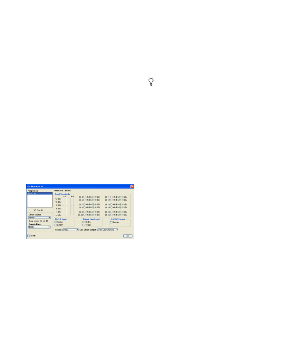
Configuring 96i I/O Controls
To configure controls for a 96i I/O:
1 With the 96i I/O selected in the Peripherals
list, configure your I/O front panel meters for input or output metering from the Meters pop-up.
2 Set input sensitivity by doing the following:
• For Inputs 1–4, set the input trim slider to
match the output level of the connected
instrument. Choices range from –12 dBV
to +4 dBu. If you do not know the output
level of the device, use the default input
trim level, then fine tune the input level
sensitivity.
• For each input 5–16 being used, select
–8 dBV or +4 dBu as appropriate to best
match the output level of the connected
instrument.
3 Set Output levels (select –10 dBV or +4 dBu).
4 Click Done.
To select analog or digital input for channels 1-2:
1 Choose Setup > Hardware, and select 96i I/O
in the Peripherals list to display the 96i I/O window.
2 Click to set Ch 1–2 Input to Analog or S/PDIF,
as appropriate.
The 96i I/O only supports analog and digital switching for channels 1–2, and only
from within the Hardware Setup and I/O
Setup dialogs. The 96i I/O does not support
path remapping within I/O Setup.
Configuring Legacy Audio Interfaces
Before you can configure a Legacy audio interface, it must first be initialized in Hardware
Setup.
To initialize a Legacy audio interface:
1 Make sure to lower the volume of your output
devices. Very loud digital noise may be emitted
before the Legacy audio interface is initialized.
2 Turn on your Legacy audio interface.
Hardware Setup for 96i I/O
You can select analog or digital input as sources
for 96i I/O channels 1–2. Only channels 1–2 can
access the S/PDIF inputs.
Pro Tools|HD Getting Started Guide56
3 From the Peripherals list, choose the primary
audio interface (the interface to which your Legacy audio interface is connected).
4 In the Main page of the Hardware Setup dia-
log, select the Legacy I/O option under Port Settings.
5 In the Peripherals list, “No Interface” is listed
twice, directly below the primary audio interface. Click the first “No Interface.” An Interface
pop-menu appears in the Hardware Setup dialog, listing supported I/O choices.
6 From the Interface pop-up, select the type of
Legacy audio interface you connected. (If your
Legacy interface does not appear, check connections and repeat from step 1, above. See also
“Offline Peripherals” on page 57.)
Page 63

After you select the type of Legacy audio interface, the Main page updates with controls that
can be configured.
7 Repeat the above steps for each additional
Legacy audio interface.
For more information on Hardware Setup
controls for each I/O, refer to its
guide.
Offline Peripherals
When a Legacy audio interface and
Pro Tools|HD peripheral are connected to your
primary Pro Tools|HD peripheral, only one can
be online at a time. An offline peripheral is indicated by brackets in the Peripherals List of the
Hardware Setup dialog. For example, if you have
a 96 I/O and an 882|20 connected to a 192 I/O,
and the 96 I/O is offline, it will appear in the Peripherals List as “[96 I/O].”
Peripherals will also go offline if the audio interface or card to which they are attached is made
inactive.
Pro Tools comes with default I/O Setup settings
that will get you started. You only need to go to
I/O Setup if you want to remap or rename the
default I/O paths or if you change your system
hardware (for example, adding an expansion
card to a 192 I/O).
Refer to the Pro Tools Reference Guide for
more information on setting up I/O paths.
To configure I/O routing in I/O Setup:
1 Choose Setup > I/O.
2 Click the Input or Output tab to display the
corresponding connections.
3 To change the name of a path or subpath,
double-click directly on the Path Name, type a
new name for the path, and press Enter.
4 To change the destination of an Input or Out-
put path or subpath, click directly on an Input
or Output Selector for an interface channel pair,
just below an audio interface icon. (This feature
is not available for the 96i I/O.)
Configuring I/O Setup
The I/O Setup dialog provides a graphical representation of the signal routing for each connected audio interface, with controls to route
physical ports to Pro Tools inputs and outputs.
These controls mirror the routing controls
found in the Hardware Setup dialog—changes
made to physical routing in one dialog are always reflected in the other. The I/O Setup dialog
also lets you label and map Pro Tools input, output, insert, and bus signal paths.
5 From the pop-up menu, select a physical port
pair (such as Analog 1–2), to route to the corresponding Pro Tools channel pair (such as A 1–2)
in the Path Name column on the left.
6 Repeat the above steps for additional channel
pairs.
Chapter 4: Launching and Configuring Pro Tools 57
Page 64

7 Click OK.
I/O Setup dialog for Pro Tools|HD system
Routing a Pro Tools Output Pair to Multiple Destinations
Pro Tools channel pairs can be routed to multiple outputs on your Digidesign audio interface
through the Hardware Setup dialog.
For example, if Pro Tools Outputs 1–2 are assigned to both Analog 1–2 and Digital 1–2, that
signal will be routed simultaneously to both
pairs of output ports on your audio interface.
This lets you send the same signal (such as a stereo pair, a stem mix, or a multichannel mix) to
multiple destinations (such as multiple mastering devices).
To route a Pro Tools output channel pair to
multiple audio interface output ports:
1 Choose Setup > Hardware.
2 From the Peripherals list, select an interface.
3 Click the Main tab.
4 Select an output pair from an Output pop-up
menu.
5 Start-click the same pop-up menu and choose
an additional output pair.
The output name updates with a plus sign (“+”)
before it to indicate that multiple output ports
are selected. In the pop-up menu, each physical
port pair assigned to that Pro Tools output pair
is indicated by a check mark.
Hardware Setup dialog for 96 I/O, Main page
6 Repeat the above steps to select additional
output destinations. The only limit to output
choices is the number of outputs available in
your system.
Backing Up your System
Configuration
After configuring your system and Pro Tools,
you should save an image of your system drive
using a backup utility such as Norton Ghost
(Windows) or Bombich Carbon Copy Cloner
(Macintosh). By doing this, you can quickly restore your system configuration and settings if
you encounter any problems.
Pro Tools|HD Getting Started Guide58
Page 65

chapter 5
Connecting Your Studio
This chapter provides general information on
connecting Pro Tools to your system, including
digital equipment, effects units, MIDI gear, and
SMPTE synchronization devices.
Refer to the 192 I/O Guide, 192 Digital I/O Guide,
96 I/O Guide, or 96i I/O Guide for specific details
regarding:
• Front and back panel connectors and indicators
• Installation of optional expansion I/O
cards (192 I/O only)
Pro Tools|HD audio interfaces need room at
their sides to maintain proper air flow for
cooling. Do not block the sides of the unit or
disconnect the internal fan. If the units are
rack-mounted in a case, remove the case
lids or doors before operating the system.
Failure to do so can result in the units overheating very quickly, which can permanently damage sensitive components.
Setting Up Your Studio
Figure 7 illustrates a typical studio setup, with a
192 I/O connected to a mixing console, effects
and other equipment.
Figure 8 illustrates a setup without a mixer,
where effects and monitoring gear are connected directly to a 96 I/O.
Chapter 5: Connecting Your Studio 59
Page 66

Example Studio Setup with a Mixing Console
Analog Inputs
Channel
Outputs
Optical
in/out
to ADAT
Analog Outputs
Digital Inputs/Outputs
to DAT recorder
Digital Effects Device
(set to external sync)
Effects Devices
Tape Returns
or Inputs
Instruments
Connected to Console
Figure 7. Typical studio configuration using a 192 I/O with mixer connections
Pro Tools|HD Getting Started Guide60
Power Amp
and Speakers
Page 67

Example Studio Setup without a Mixing Console
Mic Preamp,
Direct Box, Synth
Digital Inputs/Outputs
Analog Inputs
Analog Outputs
to DAT recorder
Optical
in/out
to ADAT
Digital Effects Device
(set to external sync)
Effects Devices
Power Amp
and Speakers
Figure 8. Typical studio configuration using a 96 I/O without a mixer
Chapter 5: Connecting Your Studio 61
Page 68

192 I/O
96i I/O
The 192 I/O features two DB-25 breakout connectors for two sets of eight inputs each, at
+4 dBu and –10 dBV respectively.
There are no –10 dBV outputs, however; analog
outputs break out from a single DB-25 output at
+4 dBu operating levels.
When driving unbalanced lines on the
192 I/O output card, leave the negative “–”
terminals disconnected. Failure to do so will
result in noisy outputs.
The 192 I/O requires a custom DB-25 snake.
Digidesign sells several different DigiSnake DB25 cables for this purpose. Contact your dealer
or Digidesign for more information.
192 Digital I/O
The 192 Digital I/O features two DB-25 breakout
connectors for two sets of eight AES/EBU or
TDIF inputs and outputs, along with a pair of
ADAT Optical ports.
The 192 Digital I/O requires a custom DB-25
snake. Digidesign sells several different DigiSnake (DB-25) cables for this purpose. Contact
your dealer or Digidesign for more information.
96 I/O
The 96 I/O analog connectors are TRS 1/4-inch
with TIP wired hot (or “+”), RING cold (or “
and SLEEVE ground. If connecting to unbalanced loads, use unbalanced TS cables.
There is one bank of eight inputs (software-switchable between +4 dBu and –10 dBV line levels
on a line-by-line basis).
There is one bank of eight outputs (that use
+4 dBu line levels).
–”),
The 96i I/O analog connectors are balanced TRS
1/4-inch with TIP wired hot (or “+”), RING cold
(or “
–”), and SLEEVE ground. If connecting to
unbalanced loads, use unbalanced TS cables.
The 96i I/O provides 16 inputs and two outputs.
Inputs 1–4 feature variable, multi-level input
sensitivity, controllable from within Pro Tools
(from –12 dBV to +4 dBu). Inputs 5–16 provide a
choice of two fixed operating levels (–8 dBV or
+4 dBu).
Outputs 1–2 are selectable between –10 dBV and
+4 dBu.
Connecting Equipment with Digital Audio Ins and Outs
Each Pro Tools|HD audio interface includes at
least one AES/EBU, S/PDIF, or Optical (ADAT)
digital option. For example, the 192 I/O includes additional AES/EBU and optical ports, as
well as TDIF, dual-wire AES/EBU at 192 kHz, and
sample rate converters. The 96i I/O provides
two channels of S/PDIF only. (See the documentation for your audio interface for details.)
The following example provides basic setup
guidelines for connecting Pro Tools to a DAT recorder. For detailed information for recording to
and from an ADAT, see “Recording To and From
Digital Devices” on page 85.
To connect your Pro Tools system to a DAT
recorder:
1 Connect the AES/EBU or S/PDIF output on the
enclosure of your Pro Tools|HD audio interface
to the AES/EBU or S/PDIF input of your DAT
deck. By default, this port is assigned to Pro
Tools Output 1–2.
Pro Tools|HD Getting Started Guide62
Page 69

2 Connect the AES/EBU or S/PDIF input on the
enclosure to the AES/EBU or S/PDIF output of
your DAT deck. Route the digital input to
Pro Tools inputs in the Hardware Setup dialog.
You can route any of the physical input or
output pairs to any of the input and output
channel assignments in the Pro Tools
mixer. (The 96i I/O does not support input
mapping, however.) For more information
see the Pro Tools Reference Guide.
Connecting Effects Units
The 192 I/O, 192 Digital I/O and 96 I/O let you
connect analog or digital effects units to your
Pro Tools system, and use them as inserts or
make them the destination for effects sends and
returns. (The 96i I/O supports a single pair of
hardware inserts using channels 1–2. See the
96i I/O Guide for more information.)
Five inserts are available on each audio channel.
Each insert can be a hardware insert (or software
plug-in), and can be mono or stereo.
When using a hardware insert, you must connect the device to matching inputs and outputs
on your system. For example, a stereo insert
could use outputs 7–8 and inputs 7–8 for the
sends and returns, respectively. Routing the
physical inputs and outputs of the interface to
Pro Tools inputs and outputs can be done in either the Hardware Setup dialog or I/O Setup dialog. From I/O Setup, inserts can also be defined, and their channels mapped to audio
interface channels. (For more information, see
the Pro Tools Reference Guide).
You can also connect effects units to your system by using any analog or digital inputs and
outputs as Auxiliary Inputs and Outputs for effects sends and returns. Once an effects unit is
attached this way, you can send a variable
amount of a track’s output to the effects unit using a send in Pro Tools.
Ten separate send controls on each Pro Tools
track allow you to route audio to any of the
available outputs connected to your system or
through any of the 128 internal busses in the
Pro Tools Mixer. Outputs can be returned to
Auxiliary Inputs for automated mixing or processing.
When you are using an effect in this send and
return type of configuration, make sure the
unit’s internal mix or balance between direct
(unprocessed) and wet (effected) signal is set so
that only the processed signal is returned to
Pro Tools. On most effect units, a balance setting of 100% (completely wet) is the appropriate
setting.
If you’ve been using an effects unit in an instrument setup, such as a guitar effects rack, you’ll
probably find the balance to be below 50%. If
the unit has separate dry and effect level knobs,
turn dry level control off. If you don’t do this,
the dry, unprocessed signal will be present in an
effect’s output along with the desired processed
sound, and you’ll have trouble accurately controlling the effect balance in your final mix.
Connecting Effects Units Digitally
To use your audio interface’s inputs and outputs
as effects sends and returns to a digital effects
device, set your interface’s Clock Source to Internal in the Hardware Setup dialog (unless it is referenced to another clock source or peripheral).
You should then set your digital effects devices
to accept an external digital clock so that they
Chapter 5: Connecting Your Studio 63
Page 70

will synchronize themselves to Pro Tools. Make
sure you set the channel pair to the digital input
in the Hardware Setup dialog (or I/O Setup dialog).
3 Connect the MIDI OUT of your MIDI device
to the MIDI IN of your MIDI interface.
4 Connect the MIDI IN of your MIDI device to
the MIDI OUT of your MIDI interface.
Connecting MIDI Devices
By adding a compatible MIDI interface to your
system, you can take advantage of all the MIDI
features of Pro Tools, including recording and
editing MIDI tracks, and synchronizing to MIDI
Time Code or MIDI beat clock.
USB MIDI interfaces work effectively with
Pro Tools systems on Windows or Macintosh.
Serial MIDI interfaces are supported on Windows systems only.
Only USB MIDI interfaces are compatible
with Pro Tools systems for Mac OS X. Modem-to-serial port adapters and serial MIDI
devices are not supported.
See Appendix C, “Configuring MIDI Studio
Setup (Windows Only)”or Appendix D,
“Configuring AMS (Mac OS X Only)” for
detailed information on how to identify external MIDI devices connected to your MIDI
interface and configure your MIDI studio
for use with Pro Tools.
To connect MIDI devices to your system:
1 Connect the MIDI interface to your computer
according to the MIDI interface’s documentation.
2 Install any MIDI driver software required by
the MIDI interface. (Once you have installed
your MIDI interface hardware and software,
confirm that it is working properly using the
procedure given in the interface’s documentation.)
Connecting SMPTE Synchronization Devices
If you intend to synchronize Pro Tools to external devices with SMPTE, your system must be
connected properly. For details on SMPTE and
synchronization, see the Pro Tools Reference
Guide or the SYNC I/O Guide.
Digidesign SYNC I/O
Digidesign’s SYNC I/O is a multi-purpose synchronization peripheral that provides all the
functions and connections needed to synchronize to a variety of devices with Pro Tools|HD.
SYNC I/O lets you synchronize Pro Tools to
LTC, VITC, and Bi-Phase/Tach, or internal for
positional reference (time code), and supports
all major clock references.
SYNC I/O integrates into the Loop Sync configuration of a Pro Tools|HD system, offering extremely fast lockup, near-sample accurate synchronization, and an exceptionally low-jitter
clock. These features provide professional performance and maximum audio fidelity under a
wide range of synchronization conditions.
For more information, refer to the SYNC I/O
Guide.
Pro Tools|HD Getting Started Guide64
Page 71

Connecting Ethernet Control Surfaces
Windows
If you are connecting your computer to an
Ethernet control surface, you will need to install
the Digidesign Ethernet software. See “Digidesign Ethernet Software for Control Surface
Support” on page 27.
Macintosh
If you are using the built-in Ethernet port or a
PCI Ethernet card to connect your computer directly (rather than across a network) to ProControl or Control|24, the TCP/IP address must be
set manually. The default manual settings will
work in most cases. Do not use DHCP unless
your computer is connected to a network that
provides DHCP services.
Chapter 5: Connecting Your Studio 65
Page 72

Pro Tools|HD Getting Started Guide66
Page 73

chapter 6
Working with Pro Tools
This tutorial of Pro Tools software introduces its
main windows and features, and also includes a
step-by-step overview of audio recording.
All features described in this chapter are explained fully in the Pro Tools Reference Guide.
You can view an electronic PDF version of the
Reference Guide by choosing it from the
Pro Tools Help menu.
Session Basics
Pro Tools projects are created and saved as sessions. Sessions store all tracks, audio, MIDI, and
other session information. Audio files, Video
files, Fade files, Region Group files, and backup
Session files are stored in folders within the Session folder.
Starting a Session
To create a new session:
1 Launch Pro Tools.
2 Choose File > New Session.
3 In the New Session dialog, set the audio file
type, sample rate, and bit depth parameters for
the new session.
New Session dialog
4 Choose where you want to save your session.
If you are using external hard drives with your
Pro Tools system, make sure you select the appropriate drive in the New Session dialog.
Session folder containing the session file and its
associated folders
5 Type a name for your session.
6 Click Save. The new session opens its Mix,
Edit, and Transport windows.
Chapter 6: Working with Pro Tools 67
Page 74
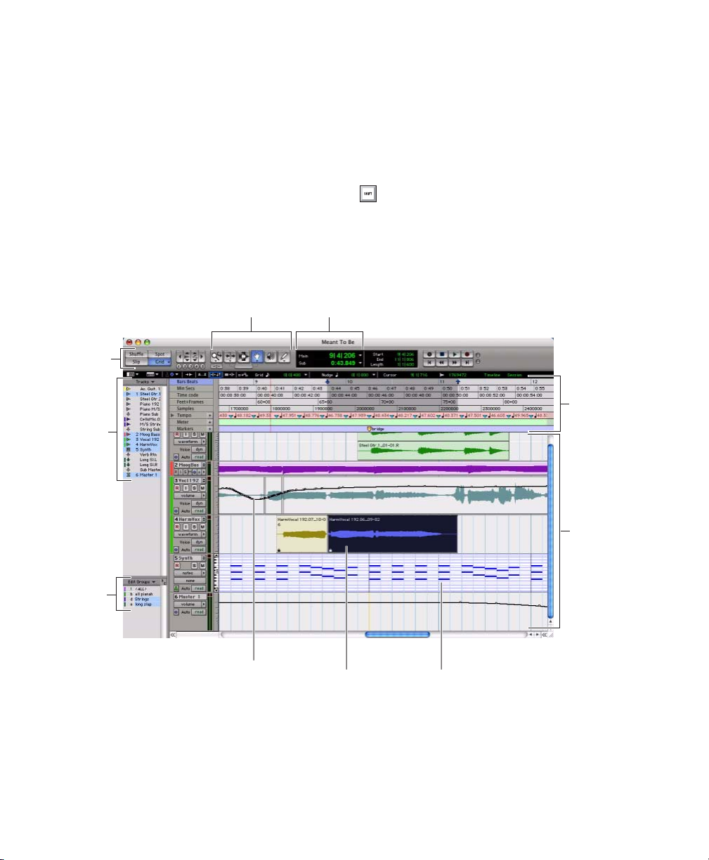
Main Windows
The Mix, Edit, and Transport windows are the
main Pro Tools work areas. You can show any of
these windows by choosing them from the Window menu.
Main and Sub CountersEdit tools
Edit
Mode
buttons
Track
List
Edit Window Displays tracks in the session along
the Timeline, for editing of audio, MIDI, and automation data.
Mix Window Displays the Pro Tools mixer, with
fader strip controls for volume, pan, solo, mute,
record enable, and signal routing.
To switch between the Edit and Mix
windows, press Control+Equals (=)
(Windows) or Command+Equals (=)
(Macintosh).
Rulers
Group
List
Figure 9. Edit window
Pro Tools|HD Getting Started Guide68
Audio region
Tracks
MIDI notesAutomation data
Page 75

Plug-In Insert
Inserts
Sends
Send controls
Pan sliders
Track controls
Volume fader Level meter
Tracks
Figure 10. Mix window
Transport Window Provides controls for Play, Stop, Rewind, Fast-Forward, Pause, and Record. The
Transport window can also show Counter and MIDI Control displays.
Figure 11. Transport window
Transport controls
MIDI controls
Main and Sub Counters
Chapter 6: Working with Pro Tools 69
Page 76

Rulers
Setting a Tempo
Pro Tools provides several different rulers to
help navigate your session.
Timebase Rulers
The Timebase rulers, displayed along the top of
the Edit window, include Bars:Beats, Minutes:Sec-
onds, Samples, Time Code, and Feet+Frames. The
current timebase determines the format of the
Main counter, and provides the basis for the
Edit window Grid.
To select a Timebase ruler:
■ Click the name of the ruler at the top left side
of the Edit window.
Selecting a Timebase ruler
For post production, select either Time Code or
Feet+Frames as the Timebase for your session in
the Rulers View.
You can set the tempo for your session by using
the Song Start Marker, located in the Tempo
ruler.
To set the session tempo with the Song Star t
Marker:
1 In the Tempo ruler, double-click the Song Start
Marker.
Song Start
Marker
Song Start Marker
2 In the Tempo Change dialog, enter the BPM
(beats per minute) value you will use for the session. The inserted tempo event replaces the default session tempo.
Conductor Rulers
The Conductor rulers, displayed just below the
Timebase rulers, include Tempo, Meter, and
Markers. The Meter and Tempo rulers indicate
changes in meter and tempo within the session.
The Markers ruler displays markers to important
track locations.
Pro Tools|HD Getting Started Guide70
Change Tempo dialog
3 To base the BPM value on a different note
value (such as an eighth note rather than the default quarter note), select a note value from the
Resolution pop-up menu.
4 Click OK.
Page 77
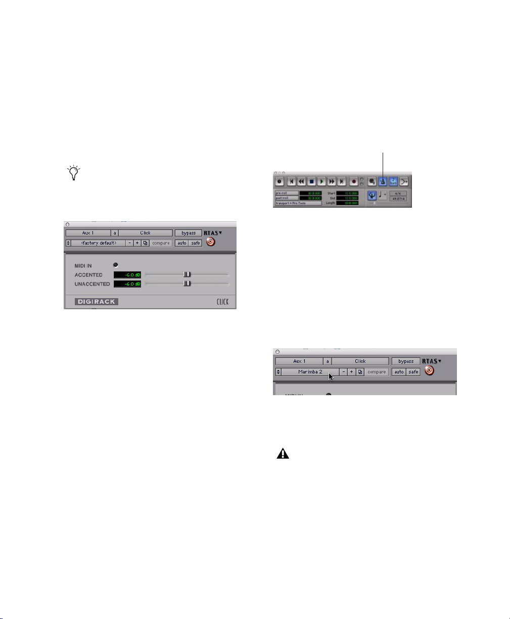
Using the Click Plug-In
The Click plug-in creates an audio click during
session playback. This works like a metronome
that you can use as a tempo reference when performing and recording.
The Click plug-in is synchronized to the tempo
and meter of the Pro Tools session, and follows
any changes in tempo and meter.
The Click plug-in is one of many plug-ins
that can be inserted on a Pro Tools track.
See “Plug-Ins” on page 96.
Click plug-in
Click Parameters
To use the Click plug-in:
1 Choose Options > Click to enable the Click
option.
– or –
Enable the Metronome Click button in the
Transport window.
Metronome Click button
Click controls in the Transport window
2 Create a mono Auxiliary Input (Aux Input)
track.
3 Insert the Click plug-in on the Auxiliary Input
track.
4 In the Click plug-in window, choose a click
sound from the Librarian pop-up menu (this
menu displays “factory default” when you first
insert the plug-in).
MIDI In LED Illuminates each time the Click
plug-in receives a click message from the
Pro Tools application, indicating the tempo.
Accented Controls the output level of the accent beat (beat 1 of each bar) of the audio click.
Unaccented Controls the output level of the unaccented beats of the audio click.
Selecting a Click sound
5 Choose Setup > Click and set the Click and
Countoff options.
The Note, Velocity, Duration, and Output
options in the Click/Countoff Options dialog are for use with MIDI instrument-based
clicks and do not affect the Click plug-in.
6 Click OK.
7 Begin playback. A click is generated according
to the tempo and meter of the current session
and the settings in the Click/Countoff Options
dialog.
Chapter 6: Working with Pro Tools 71
Page 78
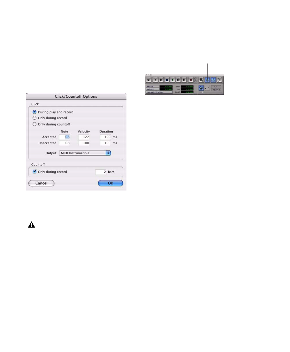
Using an External MIDI Click
Pro Tools also lets you use an external MIDI device to play the click. This feature can be turned
on and off in the Transport window, and is configured from the Click/Countoff Options dialog.
To configure and enable an external MIDI click:
1 Choose Setup > Click.
Click/Countoff Options dialog
4 During recording or playback, you can turn
the Click on or off with the Metronome Click
button in the MIDI Controls display of the
Transport window.
Metronome Click button
Click controls in the Transport window
Saving Sessions
As you build a session by adding tracks and
changing session controls, you will want to save
your work. Pro Tools provides three ways to save
sessions.
To save a session:
■ Choose File > Save, File > Save As, or
File > Save Copy In.
Save Saves the currently open session file, leaving it open for you to continue working.
2 Configure the click parameters as needed for
your MIDI sound source.
See Appendix C, “Configuring MIDI Studio
Setup (Windows Only)” or Appendix D,
“Configuring AMS (Mac OS X Only)” for
information on configuring your MIDI studio
for use with Pro Tools.
3 Choose a MIDI sound source from the Output
pop-up menu and click OK.
Pro Tools|HD Getting Started Guide72
Save As Creates a duplicate session file with the
name you choose, and leaves the duplicate open
for you to continue working. This can be useful
if you want to experiment with different arrangements in the session without affecting the
original session.
Save Copy In Saves a copy of the session file and
lets you save copies of all audio files that are
used in the session. This can be useful for archiving a session, preparing a session for transfer to another system, saving to older Pro Tools
session formats, or saving a session at another
sample rate.
Page 79
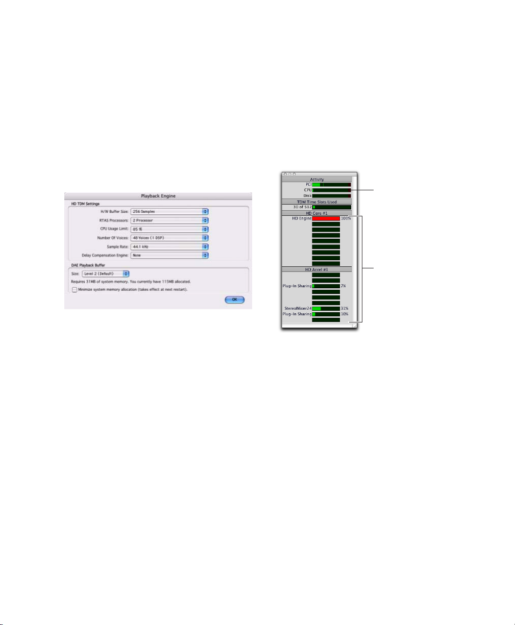
System Resources and Settings
System Usage Window
You can change specific Pro Tools system settings in the Playback Engine dialog to optimize
system performance.
Playback Engine Dialog
The Playback Engine dialog lets you adjust system buffer sizes, allocate CPU processing power,
and choose delay compensation settings in
Pro Tools.
Playback Engine dialog for Pro Tools|HD system
To configure system resources:
■ Choose Setup > Playback Engine.
See Chapter 4, “Launching and Configuring
Pro Tools” for details on configuring system settings.
The System Usage window displays approximate information on CPU load, DSP usage, and
overall disk performance. Use this window to
gauge your system’s basic processing capacity.
Monitor CPU usage if you are using RTAS plugins, and DSP usage if you are using TDM plugins.
CPU Usage meter
DSP Usage meters
Meters in the System Usage window in a new session
To view system resources and usage:
■ Choose Window > System Usage.
Chapter 6: Working with Pro Tools 73
Page 80

Transport Controls
The Transport window provides access to all
Pro Tools transport commands. Different transport controls can be displayed or hidden in this
window.
To show the Transport window:
■ Choose Window > Transport.
Online
Return to Zero
Rewind
Stop
Fast Forward
Play
Go to End
Record Enable
The Transport window can also display the following MIDI controls: Wait for Note, Metronome Click, Countoff, MIDI Merge, Tempo
Ruler Enable, and Meter and Tempo controls.
Metronome Click
Wait for Note
Tempo Ruler Enable
Transport window (MIDI Controls)
Countoff
MIDI Merge
Meter and
Tempo controls
To start and stop playback:
1 Click Play in the Transport window to begin
playback.
Transport window
To configure the Transport window:
■ Choose View > Transport and select a view op-
tion from the submenu.
The Transport window provides Play, Stop, and
other standard transport controls.
The Expanded view of the Transport window
provides pre- and post-roll, start, end, and
length indicators for Timeline selection, as well
as the Transport Master selector.
Pro Tools|HD Getting Started Guide74
2 Click Stop in the Transport window to stop
playback.
Press the Spacebar on your computer keyboard to start and stop playback.
Pro Tools starts playing from the location of
the cursor, or from the beginning of the current selection. The current setting of the
Link Timeline and Edit Selection command
in the Options menu also affects playback.
See the Pro Tools Reference Guide for more
information.
Page 81

Tracks
Pro Tools lets you create tracks for audio and
MIDI recording, submixing, routing, automating, and editing.
Pro Tools provides five types of tracks: audio
tracks, Auxiliary Input tracks, Master Faders,
MIDI tracks, and Instrument tracks. Audio
tracks, Auxiliary Inputs, Master Faders, and Instrument tracks can be mono, stereo, or any of
the supported multichannel formats for surround mixing.
Audio Tracks Record and play back audio to and
from hard disk, monitor audio input when
record-enabled, and edit audio regions
Auxiliary Inputs Audio mixer channels used for
input, routing, and submixing
Master Faders Provide master channel controls
and options for any Output or Bus path
MIDI Tracks Record, play back, and edit MIDI
data
To create multiple new track types in one step,
click the “+” button in the New Tracks dialog.
Specify the number of tracks, track type, and
track format for each additional row of new
tracks you want to create.
3 Click Create.
In the Mix window, audio tracks, Auxiliary Inputs, Master Faders, MIDI tracks, and Instrument tracks appear as vertical channel strips.
Track type is indicated by the Track Type icons
just below the faders, and by the track colors.
Instrument Tracks Combine the functions of
MIDI and Auxiliary Input tracks, letting you
control and monitor instrument plug-ins or external MIDI devices in a single channel strip.
To create a new track:
1 Choose Track > New.
New Track dialog
2 Specify the number of tracks, track type, and
channel configuration (for all types except
MIDI).
Auxiliary
Input
Audio Master
Tracks in the Mix window
track
Instrument
track
Chapter 6: Working with Pro Tools 75
MIDI
track
Fadertrack
Page 82
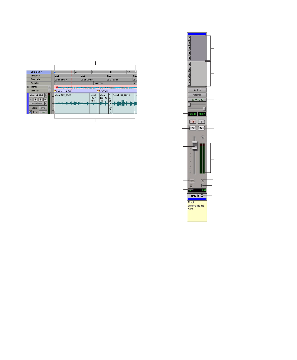
In the Edit window, tracks are displayed horizontally along the Timeline. The area in which
audio appears for each track is the Playlist.
Timeline
Inserts (up to 5)
Sends (up to 10)
Playlist
Timeline and an audio playlist in the Edit window
Audio tracks, Auxiliary Inputs, Master Faders,
MIDI tracks, and Instrument tracks can all be
automated. See “Mix Automation” on page 97
for more information.
Audio Tracks
Audio tracks, Auxiliary Inputs, and Master Faders share many identical controls. Figure 12
shows the controls found in audio or Auxiliary
Input tracks. Master Faders provide all the same
features as audio tracks and Auxiliary Input
tracks, with the following exceptions:
Input Selector A Master Fader’s output assignment determines its input, or source.
Output Path
selector
Pan indicator
Record Enable
button
Solo button
Volume fader
Voice selector
Volume indicator
Color bar
Input Path selector
Automation mode
selector
Pan sliders
Mute button
Output window
button
Level meter
Group ID
Track Type indicator
Track name
Track comment area
Figure 12. Stereo audio track in the Mix window
Inserts Inserts on Master Faders are post-fader
only. (Audio track and Auxiliary Input track inserts are all pre-fader.)
Sends Master Faders do not provide sends. To
send an output to another destination, use an
Auxiliary Input track.
Pro Tools|HD Getting Started Guide76
Page 83

MIDI Tracks
Instrument Tracks
MIDI tracks provide volume, solo, and mute, in
addition to MIDI input, output, channel, and
program (patch) controls. Figure 13 shows the
controls found in MIDI tracks.
MIDI Input selector
MIDI Output selector
Pan slider
Record Enable
button
Solo button
Volume
fader
Patch Select
Volume indicator
Color bar
Automation Mode
selector
Pan indicator
Mute button
MIDI Velocity meter
Group ID
Track Type indicator
Track name
Track comment
Figure 13. MIDI track in the Mix window
Instrument tracks have many controls in common with audio tracks, and also have an additional Instruments View, which provides controls for MIDI input, output, mute, volume, and
pan. Figure 14 shows the controls found in Instrument tracks.
MIDI Input selector
MIDI Output selector
MIDI Volume
MIDI Pan
Audio Output Path
selector
Pan sliders
Record Enable
button
Solo button
Volume
fader
MIDI Velocity meter
MIDI Mute button
Inserts (up to 5)
Sends (up to 10)
Audio Input Path
selector
Automation Mode
selector
Pan indicators
Mute button
Output Window button
Level meter
Patch Select
Volume indicator
Color bar
Group ID
Track Type indicator
Track name
Track comment area
Figure 14. Stereo Instrument track in the Mix window
Chapter 6: Working with Pro Tools 77
Page 84

Region List
Navigating in a Session
A region is a piece of audio or MIDI data that can
also have associated automation data. For example, a region could be a loop, a guitar riff, a verse
of a song, a sound effect, a piece of dialog, or an
entire sound file.
In Pro Tools, regions are created from audio or
MIDI files, and can be arranged in audio, MIDI,
and Instrument track playlists.
All regions that are recorded, imported, or created by editing appear in the Region List. Regions can be dragged from the list to tracks and
arranged in any order. Audio regions can also be
auditioned from the Region List by Alt-clicking
(Windows) or Option-clicking (Macintosh) the
audio region name. The Region List pop-up
menu provides features for managing regions
and files (such as searching, sorting, or selecting
regions, and importing or exporting files).
Drag border to resize
width of Region List
Click Region List button
for pop-up menu
Pro Tools provides many ways to navigate in a
session, including using the mouse or entering a
memory location into one of the counters.
To navigate to a location in the Edit window:
1 In the Options menu, make sure Link Time-
line and Edit Selection is enabled.
2 Enable the Selector tool at the top of the Edit
window by clicking it.
Selector tool
Edit tools in Edit window
3 Click in a track or Timebase ruler. The cursor
appears at the selected location and the
counters display the current time location.
Click in a track or on a Timebase ruler
Click to show/hide Region List
Region List
For more information on the Region List,
see the Pro Tools Reference Guide.
Pro Tools|HD Getting Started Guide78
Clicking with the Selector tool in the Edit window
Page 85
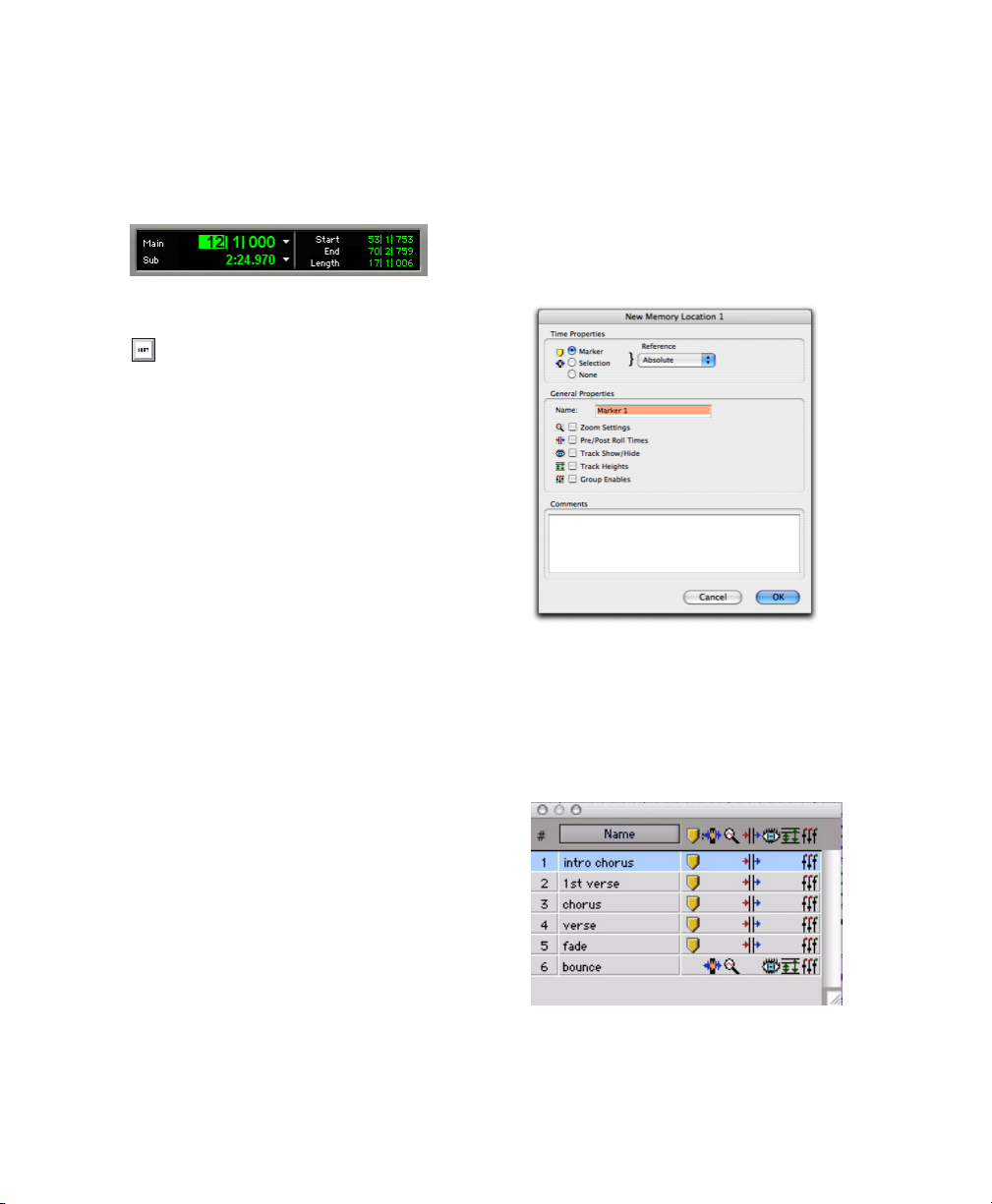
To navigate using the counters:
1 Click in the Main Counter and enter a loca-
tion using your computer keyboard.
2 Press Enter (Windows) or Return (Macintosh).
Navigating with the Main Counter
Press the * (asterisk) key on the numeric
keypad as an alternative to clicking in the
counter. (The cursor will always appear in
the Transport window’s Main Counter if it
is displayed.)
Memory Locations
Memory Locations and markers provide another
way to navigate within sessions. Memory Locations appear as markers under the Timebase rulers. You can store up to 999 Memory Location s
or markers in a session.
To define a Memory Location:
1 Navigate to the point where you want to store
a Memory Location or marker.
– or –
Begin playback somewhere before the point
where you want to store a Memory Location or
marker.
In the New Memory Location dialog, you can
define a marker, store a selection, or store any
combination of the other available settings.
These settings include Track Height, Group Enables, Pre- and Post-Roll values, and Track
Show/Hide status.
3 Choose settings for the Memory Location and
click OK.
New Memory Location dialog
To go to a stored Memor y Location:
1 Choose Window > Memory Locations.
2 In the Memory Locations window, click the
name of the memory location.
2 Create a memory location by doing one of the
following:
• Press Enter on the numeric keypad.
– or –
• Click the Add Marker/Memory Location
(“+”) button, located to the left of the
Markers ruler.
Memory Locations window
Chapter 6: Working with Pro Tools 79
Page 86

Viewing and Zooming
When viewing tracks in the Edit window, you
can adjust the height of tracks as well as zoom in
vertically and horizontally using the Track
Height selector and Zoom tools.
Zoom In/Out buttons
Zoom Preset
buttons
Zoom and Track Height tools in the Edit window
Zoomer tool
To change track height:
■ Click the Track Height selector (the scaled ver-
tical bar at the left of the track), and select a
track height from the pop-up menu.
You can apply many commands, including
track height selection, to more than just a
single track. Hold down the Alt key (Windows) or Option key (Macintosh) while performing an operation to apply it to all
tracks. Hold down both the Shift and Alt
keys (Windows) or Shift and Option keys
(Macintosh) while performing an operation
to apply it to all selected tracks.
Zoom Toggle
button
Track Height selector
To Zoom in or out on any area of a track in the Edit
window:
1 Click to select the Zoomer tool.
2 Click or drag with the Zoomer tool to zoom in
horizontally for a track or ruler.
– or –
Press Alt (Windows) or Option (Macintosh) and
click with the Zoomer tool to zoom out horizontally for a track or ruler.
To zoom in or out incrementally:
■ Click the appropriate Zoom button:
•Zoom Out button (Left Arrow)
• Zoom In button (Right Arrow)
• Audio or MIDI Zoom buttons, to increase
or decrease vertical zoom of the corresponding track type
To zoom in or out continuously:
1 Select the Zoom tool.
2 Hold the Start key (Windows) or Control
(Macintosh) and drag in a track as follows:
• Drag up to zoom in vertically
• Drag down to zoom out vertically
• Drag to the right to zoom in horizontally
• Drag to the left to zoom out horizontally
Pro Tools|HD Getting Started Guide80
Page 87

Zoom Toggle
Zoom Presets
The Zoom Toggle button lets you store a zoom
state and toggle between it and the current
zoom state. When Zoom Toggle is enabled, the
Edit window displays the stored zoom state.
When Zoom Toggle is disabled, the Edit window
reverts to the last zoom state.
To store a zoom state using Zoom Toggle:
1 Make an Edit selection.
2 Click the Zoom Toggle button so that it is
highlighted.
Zoom Toggle button
Zoom Toggle button in the Tool bar
3 Adjust Track Height, Vertical Zoom, Track
view, and the Grid setting.
4 Make any desired edits.
5 Click the lit Zoom Toggle button again to re-
vert to the last zoom state.
6 Make another edit selection and click the
Zoom Toggle button to recall the stored zoom
state, and continue editing.
Pro Tools provides five Zoom Preset buttons.
You can use these to immediately return to established zoom levels. You can define the magnification level for each preset, on a session-bysession basis.
To store a new Zoom preset definition:
1 Use the Zoom tool to establish a Zoom setting.
2 Click a Zoom Preset button (1–5) and choose
Save Zoom Preset from the Zoom Preset pop-up
menu.
Zoom Preset pop-up menu
To recall a saved Zoom preset:
■ Click the corresponding Zoom Preset button
(1–5).
Using Memory Locations for Zoom Control
Pro Tools Memory Locations let you store many
attributes with each marker or Memory Location, including Track Height and Zoom Settings.
By creating Memory Locations that are neither
markers nor selections, but have Track Height,
Zoom Settings, or other options enabled, you
can use Memory Locations to zoom in and out
using just the numeric keypad.
For more information on creating memory locations, see “Memory Locations” on page 79.
Chapter 6: Working with Pro Tools 81
Page 88
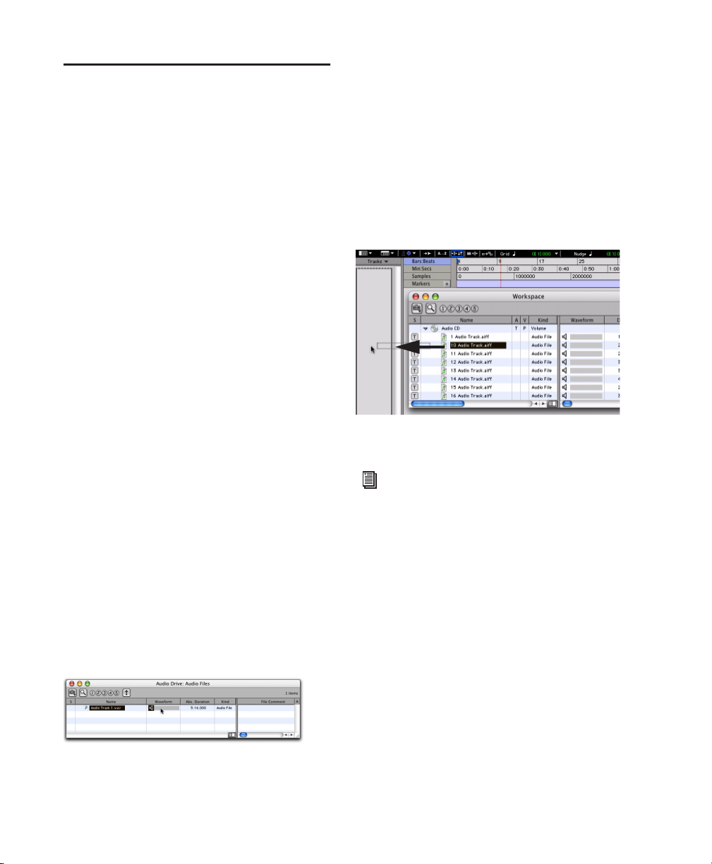
Importing Data into Pro Tools Sessions
Pro Tools lets you import audio, MIDI, video,
and a wide range of Pro Tools session data into
your current session.
4 Do one of the following:
■ Drag audio files from the Workspace browser
to the Track List in the Edit window to import
the files to new audio tracks (they will also appear as regions in the Region List).
– or –
Importing Audio
Pro Tools lets you import audio files from your
hard drive or from a CD. This is very useful if
you have audio files already recorded to disk or
if you are working with CD-based sample libraries that you want to use in a session.
To import audio files or regions from disk:
■ Choose File > Import > Audio to Track to im-
port files and regions to new audio tracks (they
will also appear as regions in the Region List).
– or –
■ Choose File > Import > Audio to Region List to
import files and regions to the Region List only.
To import a CD audio track:
1 Put the source CD into your computer’s CD
drive.
2 Choose Window > Workspace and click the
Audio CD icon to show the files on the CD.
3 Click the speaker icon in the waveform col-
umn of the Workspace browser to audition the
corresponding file. Press the Spacebar to stop
playback.
■ Drag audio files from the Workspace browser
to the Region List in the Edit window to import
the files to the Region List only.
Dragging an audio file from the Workspace Browser to
the Edit window Track List
For more information on searching, auditioning, and importing audio with DigiBase,
refer to the DigiBase Guide.
Importing MIDI
Pro Tools lets you import MIDI files into the Region List or directly into MIDI tracks in a session.
To import MIDI files into the Region List:
■ Choose File > Import > MIDI to Region List.
Auditioning an audio file in the Workspace Browser
Pro Tools|HD Getting Started Guide82
To import MIDI files to tracks:
1 Choose Window > Workspace and locate the
MIDI files you want to import.
Page 89

2 Drag MIDI files from the Workspace browser
to the Track List.
Dragging a MIDI file from the Workspace Browser to the
Edit window Track List
3 In the Import MIDI Settings dialog box,
choose the import location and settings for the
MIDI you are importing.
Basic Recording
This section describes how to record audio and
MIDI into Pro Tools.
Preparing for Recording
To prepare an audio track for recording:
1 Verify the connections to your instruments.
Refer to the guide for your audio interface for
more information about setting up your studio
and monitoring output.
2 Choose Track > New. Specify 1 Mono Audio
Track, and click Create.
3 In the Mix window, click the Audio Input Path
selector on the new track.
Audio Input Path selector
Import MIDI Settings dialog
Importing Files from Windows Explorer and Macintosh Finder
Pro Tools lets you drag and drop audio, MIDI,
region group, REX, and ACID files directly from
Windows Explorer or Macintosh Finder to the
Timeline or the Region List.
For more information on importing data
into Pro Tools sessions, see the Pro Tools
Reference Guide.
Routing an input to a mono track
4 From the pop-up menu, select the input you
want to record. The menu displays the names of
the inputs as defined in the I/O Setup dialog.
Chapter 6: Working with Pro Tools 83
Page 90
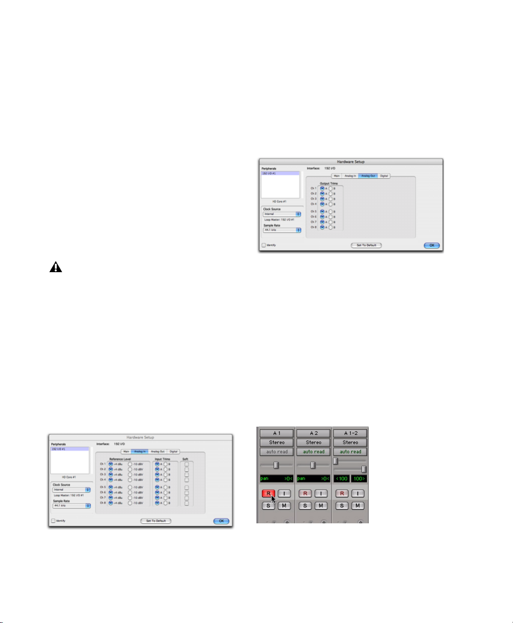
Setting Input Levels
5 Click OK.
Adjust the level of the input at the source (instrument, mic pre-amp, or mixer) to set
Pro Tools recording levels.
When you feed a signal into Pro Tools, make
sure to adjust the input level to optimize the dynamic range and signal-to-noise ratio of the recorded file. If the input level is too low, you will
not take full advantage of the dynamic range of
your Pro Tools system. If the input level is too
high, the waveform will be clipped, distorting
the recording.
Try to set levels so that they register within the
top 6 dB of the input meter without triggering
the clipping indicator on your audio interface.
Set input levels to avoid clipping. Clipping
is indicated by the red Peak LEDs on the audio interface and by the red indicator at the
top of each on-screen meter.
Setting Reference Levels
To configure input levels for the 192 I/O:
1 In Pro Tools, choose Setup > Hardware.
2 If you are using multiple audio interfaces, se-
lect an interface in the Peripherals list.
3 In the Interface area, click the Analog In tab.
To configure output levels for the 192 I/O:
1 In Pro Tools, choose Setup > Hardware.
2 If you are using multiple audio interfaces, se-
lect an interface in the Peripherals list.
3 In the Interface area, click the Analog Out tab.
Hardware Setup, 192 I/O Analog Out settings
4 Set the Reference Level for each Output Chan-
nel.
5 Click OK.
Recording an Audio Track
To record an audio track:
1 Assign the input for a track and set its input
levels.
2 Click the Track Record Enable button.
Hardware Setup, 192 I/O Analog In settings
4 Set the Reference Level for each Input Chan-
nel.
Pro Tools|HD Getting Started Guide84
Record enabling a track in the Mix window
Page 91

3 Choose Window > Transport to display the
Transport window.
Recording To and From Digital Devices
Return to Zero
Rewind
Online
Transport window
4 Click Return to Zero to start recording from
Stop
Fast Forward
Play
Go to End
Record Enable
the beginning of the session. You can also record
to a selection in a track, or from the cursor location in the Edit window.
5 Click Record Enable in the Transport window
to enable recording.
6 Click Play or press the Spacebar to record on
all record-enabled tracks.
7 Record your performance.
8 Click Stop in the Transport window or press
the Spacebar when you are finished recording.
To play back a recorded track:
1 Click the track’s Record Enable button a sec-
ond time to take it out of Record mode.
2 Click Play in the Transport window or press
the Spacebar to start playback.
3 Click Stop in the Transport window or press
the Spacebar to stop playback.
You can digitally transfer up to 16 tracks on a
single 192 I/O or 192 Digital I/O, up to a system
maximum of 96 inputs. Using a single 96 I/O
audio interface, you can digitally transfer as
many as eight tracks at a time to or from a digital device. Using a single 96i I/O audio interface,
you can digitally transfer up to two tracks at a
time to or from any S/PDIF-compatible device.
Setting Digital Format and Clock Source
Before recording from a digital source, make
sure you have enabled the appropriate Clock
Source and Digital Format in the Hardware
Setup dialog. Digital Format defaults to
AES/EBU, meaning your Pro Tools|HD I/O will
listen to the AES/EBU (Encl) In port for digital
clock (if any). If you want to record from a DAT
machine connected to your S/PDIF RCA inputs,
select S/PDIF Format. If you are using multiple
Pro Tools|HD interfaces, be sure to configure the
appropriate interface in the Hardware Setup dialog.
After enabling a different digital format, appropriate clock signals will become available in the
Clock Source selector. If you have multiple interfaces, choose the appropriate clock source on
each Pro Tools|HD I/O.
Using Pro Tools Output Pairs
Because of the way that outputs function in
Pro Tools, each track looks for a stereo output
pair. In order to send eight channels out of
Pro Tools from its Optical port, you have to send
four pairs of Pro Tools tracks (each pair panned
hard left and right) to four pairs of Optical digital outputs.
Chapter 6: Working with Pro Tools 85
Page 92

Working with 88.2 kHz or Higher Sample Rates
If the session sample rate is 88.2 kHz or higher,
Optical (ADAT) and TDIF input sources can still
be used with Digidesign’s 192 I/O, but the sample rate conversion option must be enabled.
96 I/O and 96i I/O audio interfaces do not have
sample rate conversion capability. On the
96 I/O, the Optical (ADAT) port will go offline
with sample rates above 48 kHz.
When the sample rate conversion option is disabled, signal does not pass through the sample
rate converter.
To record ADAT tracks into Pro Tools:
1 Connect the Optical Out connector from your
ADAT deck to the Optical In connector on the
back of your Pro Tools|HD audio interface.
2 Open or create a session in Pro Tools.
3 Record Enable up to eight audio tracks.
4 For each track, click its Input Selector and as-
sign Inputs 9–16 to your eight tracks.
Analog inputs
To enable sample rate conversion on the 192 I/O:
1 Choose Setup > Hardware in Pro Tools.
2 From the Peripherals list, select the primary
192 I/O audio interface.
3 Click the Digital tab.
4 Select an Input Format (AES/EBU 1–8, ADAT
1–8, or TDIF 1–8).
5 Enable the SR Conversion option for channel
pairs.
Recording to and from an ADAT
The 192 I/O and 192 Digital I/O each provide
16 channels of ADAT input and output (eight
on the chassis, eight on the digital card). These
inputs and outputs are numbered 9–16 and
17–24 by default in the Pro Tools Hardware
Setup and I/O Setup dialogs.
The 96 I/O provides eight channels of ADAT input and output. These inputs and outputs are labeled Optical 1–8 (ADAT) by default in the
Pro Tools Hardware Setup and I/O Setup dialogs.
Optical (ADAT)
inputs
Routing an Optical input pair to a mono track
5 Verify that Pro Tools is synchronized to Opti-
cal in the Hardware Setup dialog, and that the
Optical Format is set to ADAT.
6 Click Record Enable in the Transport window.
7 Click Play in the Transport window to begin
recording, then press Play on the ADAT.
8 When playback from the ADAT tape is fin-
ished, click Stop in the Transport window, or
press the Spacebar.
(The 96i I/O does not support ADAT Optical input or output.)
Pro Tools|HD Getting Started Guide86
Page 93

To record Pro Tools tracks to an ADAT:
1 Connect the Optical Out connector on your
Pro Tools|HD audio interface to the Optical In
connector on the back of the ADAT deck.
2 Open the session you want to record to ADAT.
3 Record Enable up to eight tracks on the ADAT.
4 On the ADAT, enable Digital In.
5 In Pro Tools, pan the four pairs of tracks you
want to record to ADAT so that each pair is
panned hard stereo (one track of each pair is
panned all the way left, and the other is panned
all the way right).
6 Route each track pair to a separate Optical out-
put pair by selecting from the Output pop-up
menu for each track.
7 Verify that Pro Tools is synchronized to Inter-
nal in the Hardware Setup dialog.
8 Start recording on the ADAT, then click Play in
the Pro Tools Transport window. When playback is complete, stop both systems.
Recording MIDI
Instrument tracks combine a MIDI track and
Auxiliary Input into a single channel strip that
provides both MIDI and audio capabilities. Instrument tracks let you record MIDI and monitor audio from software and hardware instruments.
To create an Instrument track and configure it for
recording:
1 Choose Setup > MIDI > Input Devices and
make sure your input device is selected in the
MIDI Input Enable window, and Click OK.
2 Choose Track > New and specify 1 Mono In-
strument Track, then click Create.
3 Select View > Mix Window > Instruments to
display the MIDI controls at the top of the Instrument track in the Mix window.
4 Click the track’s MIDI Input selector and as-
sign the device and channel to be recorded, or
leave it set to All.
MIDI Input selector
MIDI Input selector in an Instrument track
Chapter 6: Working with Pro Tools 87
Page 94
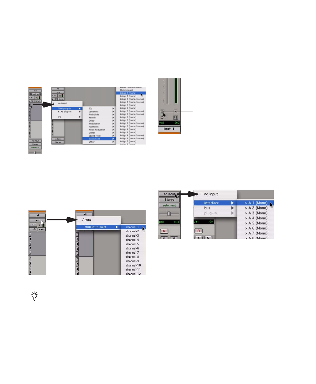
5 Do one of the following, depending on the
type of instrument you are using:
• If you are using an instrument plug-in,
click an Insert selector and insert the plugin on the Instrument track. The track’s
MIDI output is automatically assigned to
the instrument plug-in.
Inserting an instrument plug-in on an Instrument track
• If you are using an external MIDI device,
click the track’s MIDI Output selector (at
the top of the Instrument track) and assign
it to an available device and channel (the
choices will vary depending on the device).
6 You can assign a default program change to
the track by clicking the Patch Select button in
the Mix window and making the necessary selections for program and bank select, and then
clicking Done. Default program changes are
sent when playing the track.
Patch Select button
Patch Select button in an Instrument track
7 If you are using an external MIDI device and
connected its audio output to an audio interface
for monitoring in Pro Tools, click the Audio Input Path selector of the Instrument track and
choose the corresponding audio input.
MIDI Output selector in an Instrument track
If your connected MIDI device does not appear, check that you have configured your
computer and its MIDI settings. See
Appendix C, “Configuring MIDI Studio
Setup (Windows Only)” or Appendix D,
“Configuring AMS (Mac OS X Only)” for
more information.
Pro Tools|HD Getting Started Guide88
Choosing an audio input for an Instrument track
8 Click the Track Record Enable button to en-
able the Instrument track for MIDI recording.
9 Make sure Options > MIDI Thru is selected.
Page 95
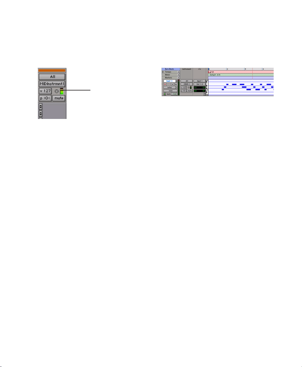
10 Play some notes on your MIDI controller and
look for the track’s MIDI Velocity meter to
move. Remember, MIDI is not audio, and the
MIDI Velocity meter is not registering sound,
but MIDI activity.
MIDI Velocity meter
MIDI Velocity meter showing MIDI activity
11 Adjust the audio output level of the Instru-
ment track with its Volume fader.
To record MIDI on the Instrument track:
1 Verify that the Instrument track you want to
record to is record-enabled and receiving MIDI.
2 In the Transport window, click Return to Zero
to start recording from the beginning of the session. You can also record to a selection in a
track, or from the cursor location in the Edit
window.
6 When you have finished recording, click Stop
in the Transport window, or press the Spacebar.
The newly recorded MIDI data appears as a MIDI
region on the track in the Edit window, as well
as in the Region List.
MIDI data in the Instrument track
To play back recorded MIDI data:
1 Click the Track Record Enable button to take
the Instrument track out of Record mode.
2 In the Transport window, click Return To Zero
to play back from the beginning of the track.
3 Click Play in the Transport window to begin
playback. The recorded MIDI data plays back
through the track’s assigned instrument and
channel.
3 Click Record Enable in the Transport window.
4 Do one of the following:
• Click Play in the Transport window or press
the Spacebar to begin recording.
• If you are using Wait for Note, the Play,
Record, and Wait for Note buttons flash.
Recording begins when the first MIDI
event is received.
• If you are using Countoff, click Play. The
Record Enable and Play buttons flash during the Countoff, then recording begins.
5 Play your MIDI controller or input device.
Chapter 6: Working with Pro Tools 89
Page 96

Editing
Pro Tools provides several tools for editing audio
and MIDI. In the Edit window, audio and MIDI
data can be edited into regions or repeated in
different locations, to create loops, re-arrange
sections or entire songs, or to assemble tracks using material from multiple takes.
The Edit mode affects the movement and placement of audio and MIDI regions (and individual
MIDI notes), how commands like Copy and
Paste function, and also how the various Edit
tools (Trimmer, Selector, Grabber, and Pencil)
work.
For detailed descriptions of the Edit modes,
see the Pro Tools Reference Guide.
Edit modes
Edit modes and tools
Audio and MIDI editing are typically used to:
• Fix or replace mistakes.
• Re-arrange songs and projects.
• Clean up track timing and rhythm by
aligning hits to Grid values like bars and
beats, time code, grooves, or other timebases.
• Create final tracks using selections from
multiple takes (also known as a comp
tracks).
Edit tools
Edit Modes
Pro Tools has the following Edit modes: Shuffle,
Spot, Slip, and two Grid modes, Absolute (standard Pro Tools Grid mode), and Relative.
The Edit mode is selected by clicking the corresponding button in the upper left of the Edit
window.
Edit Tools
Pro Tools has seven Edit tools: Zoomer, Trimmer, Selector, Grabber, Scrubber, Pencil, and
Smart Tool. Select an Edit tool by clicking it in
the Edit window. The Zoomer, Trimmer, Grabber, and Pencil tools have multiple modes,
which you can select from a pop-up menu when
you click the tool.
Trimmer tool Grabber tool
Selector tool
Edit tools in Edit window
Press the Escape key to toggle through the
Edit tools.
For detailed descriptions of the Edit tools,
see the Pro Tools Reference Guide.
Scrubber tool
Pencil toolSmart ToolZoomer tool
Edit mode buttons
Press F1 (Shuffle), F2 (Slip), F3 (Spot), and
F4 (Grid) to set the Edit mode.
Pro Tools|HD Getting Started Guide90
Page 97
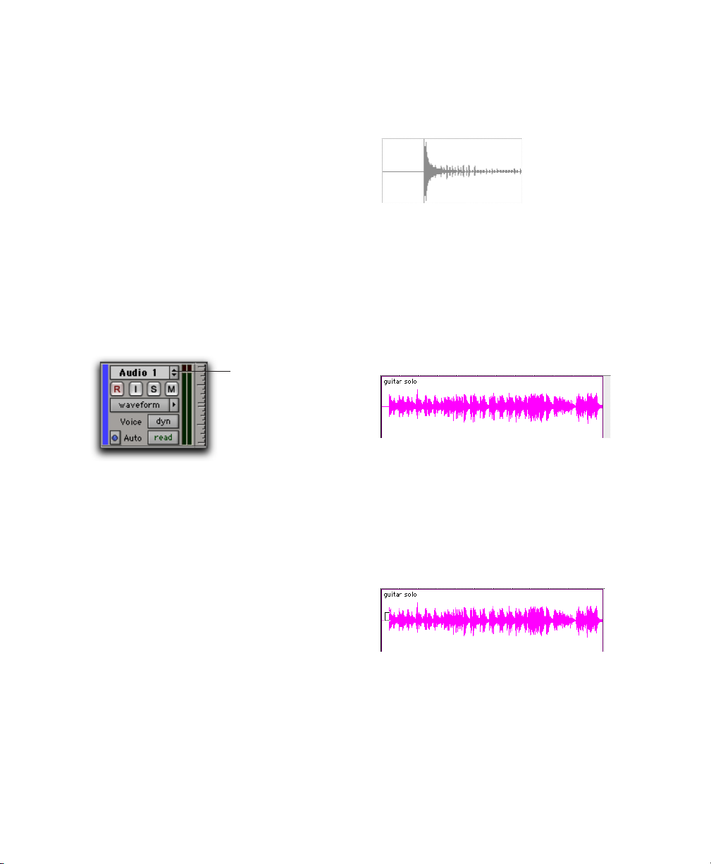
Playlists and Nondestructive Editing
Editing Regions
Playlists let you create and retrieve multiple versions of track edits. A playlist can be a complete
take, an overdub, or an arrangement of selections from multiple takes. You can duplicate
playlists to save edits in their current state, then
continue making additional edits to the new
playlist, knowing you can always go back to the
previous version.
To create multiple playlists for editing:
1 Start with a track on which you want to try
different edits.
2 Click the Playlist selector and choose Dupli-
cate.
Playlist selector
Playlist selector and pop-up menu
3 Name the duplicated playlist and click OK.
4 Make your first series of edits.
5 Return to the original playlist by clicking the
Playlist selector and selecting its name.
6 Repeat steps 2–5 for any further edits.
The Edit tools in Pro Tools are used to edit regions in the Edit window.
Audio region
Trimming Regions
After recording an audio track, you will have an
audio region on that track. If there is some silence at the beginning of the region, or there is
some extra audio at the end of the region, you
can use the Trimmer tool in Slip mode to
shorten the beginning or end of the region.
Audio region on a track
To trim an audio region:
1 Select Slip mode.
2 Select the Trimmer tool.
3 Move the cursor near the beginning of the au-
dio region (notice the cursor displays as a “[”).
In this way, you can try out different edits of a
track, and switch back and forth between playlists for comparison.
Trimming the beginning of a region
4 Click at the beginning of the region and drag
right to shorten the region.
Chapter 6: Working with Pro Tools 91
Page 98

5 Move the cursor near the end of the audio re-
gion (notice the cursor displays as a “]”).
Trimming the end of a region
Add Tempo Change
Add Meter Change
6 Click at the end of the region and drag left to
shorten the region.
The trimmed region
You can also extend a region using the Trimmer
tool if there is audio data beyond the current
boundaries of a region. If extending the region’s
beginning, drag to the left; if extending the region’s end, drag to the right.
Arranging Regions
There are many ways to edit and arrange regions; the following example demonstrates how
you might create and arrange a drum loop to
compose a rhythm track.
To create and arrange a rhythm sequence:
1 Open or create a session in Pro Tools.
2 Set the session meter and tempo by doing the
following in the Edit window:
• Click the Ruler View selector and select
both Tempo and Meter.
• Click the Add Tempo Change button and
specify the tempo.
• Click the Add Meter Change button and
specify the meter.
Add Tempo Change and Add Meter Change buttons
3 Click the Grid mode button to put Pro Tools
in Grid mode.
4 Prepare to record using a click (see “Using the
Click Plug-In” on page 71 or “Using an External
MIDI Click” on page 72).
5 Record a drum track (see “Recording an Audio
Track” on page 84) keeping in mind that you
want to use only the best bar (measure). Your recording should fit the grid at the specified
tempo and meter.
– or –
Import an existing audio file, such as a drum
loop from a sample library, and place it on an
audio track (see “Importing Audio” on page 82).
6 Click the Selector tool, then drag on the wave-
form to make a one-bar selection. Note that the
selection snaps to the specified grid.
Making a selection in Grid mode
7 Choose Track > New and create a new Stereo
Audio track.
8 Click the Grabber tool and select the Separa-
tion Grabber tool.
Pro Tools|HD Getting Started Guide92
Page 99

9 With the Separation Grabber tool, drag the se-
lection to the beginning of the new audio track.
A new region is created and appears at the beginning of the new track.
Dragging a selection with the Separation Grabber tool
10 With the new region still selected, choose
Region >Loop.
Mixing
The Pro Tools mix environment provides many
familiar channel strip controls for setting volume, pan, solo, and mute. Mixer and I/O controls can be shown in both the Mix and Edit
windows.
To view the Mix window:
■ Select Window > Mix.
Press Control+Equals (=) (Windows) or
Command+Equals (=) (Macintosh) to
switch between the Edit and Mix windows.
Using Channel Strip Controls
The following controls are common to Audio,
Auxiliary Input, and Instrument tracks.
Volume Fader Increase or decrease the track level
by dragging its Volume fader up or down.
Region Looping dialog
11 In the Region Looping dialog, enter the
number times you want to loop the region, and
click OK.
You now have a new rhythm track with a
“looped” (repeated) phrase.
You can use these editing tools and Beat Detective to do much more advanced editing of regions.
Grouping Regions
The Region Groups feature in Pro Tools lets you
group regions on multiple adjacent audio,
MIDI, and Instrument tracks. Region Groups are
useful for groove and tempo manipulation, editing, and arranging.
For more information on Region Groups, see
the Pro Tools Reference Guide.
Pan Slider Pan a track left or right in the mix by
dragging its Pan slider left or right.
Solo Button Solo a track (muting all other tracks)
by clicking its Solo button.
Mute Button Mute a track by clicking its Mute
button.
Chapter 6: Working with Pro Tools 93
Page 100

Basic Signal Routing
Signal routing is accomplished by assigning
track inputs and outputs. Audio track inputs can
be from any hardware input or bus path. Once
recorded, an audio track’s input is its audio file
on disk. Auxiliary Inputs can be any hardware
input or internal bus path. For all types of audio
tracks, outputs can be routed to any hardware
output or internal bus path.
Together, these signal routing features let you
set up virtually any mixer architecture for your
projects, including submixing, sends and returns for effects processing, and multichannel
mixing for surround.
Send and Return Submixing for Effects Processing
When you are submixing for reverb, delay, and
similar effects processing, you can use sends and
Auxiliary Inputs to achieve traditional send/return bussing. You can use a real-time plug-in
(see “Plug-Ins” on page 96) or a hardware I/O insert (see “Connecting Effects Units” on page 63)
as a shared resource for all tracks included in a
submix. The wet/dry balance in the mix can be
controlled using the track faders (dry level) and
Auxiliary Input fader (wet, or effect return
level).
Creating a Send
Pro Tools provides up to ten sends per audio
track. A send can be mono or stereo, routing to
an output or one of 128 internal bus paths.
To assign a send on a track:
1 Make sure the Sends you want to use are visi-
ble in the Mix window (View > Mix Window >
Sends A–E or Sends F–J).
2 In the Mix window, click a Send selector on an
audio track and choose a bus path from the popup menu.
Assigning a send to a stereo bus path
3 Set the output level of the send. You can set
the send level to zero by Alt-clicking (Windows)
or Option-clicking (Macintosh) the Send fader.
You can configure the default level for
new sends to be
–∞ or at unity gain
(0 dB) by enabling or disabling the Sends
Default To “–INF” option in the
Operation Preferences page.
Pro Tools|HD Getting Started Guide94
 Loading...