


Pro Tools
AVoption|XL Guide
Version 6.1 on Windows or Macintosh
Version 5.3.x on Windows or Macintosh
Version 5.1.3 on Macintosh
Digidesign
2001 Junipero Serra Boulevard
Daly City, CA 94014-3886 USA
tel: 650·731·6300
fax: 650·731·6399
Technical Support (USA)
tel: 650·731·6100
fax: 650·731·6384
Product Information (USA)
tel: 650·731·6102
tel: 800·333·2137
International Offices
Visit the Digidesign Web site
for contact information
Web Site
www.digidesign.com

Copyright
This guide is copyrighted ©2003 by Digidesign, a division of
Avid Technology, Inc. (hereafter “Digidesign”), with all rights
reserved. Under copyright laws, this guide may not be
duplicated in whole or in part without the written consent of
Digidesign.
DIGIDESIGN, AVID and PRO TOOLS are trademarks or
registered trademarks of Digidesign and/or Avid Technology,
Inc. All other trademarks are the property of their respective
owners.
All features and specifications subject to change without
notice.
PN 932711597-00 REV A 06/03

contents
Chapter 1. Introduction to Pro Tools AVoption|XL
AVoption|XL Components
FilmFrame
. . . . . . . . . . . . . . . . . . . . . . . . . . . . . . . . . . . . . . . . . . . . . . . . . . . . . . . . . . . . . 2
Chapter 2. AVoption|XL Hardware Overview
AVoption|XL Hardware Capabilities
Compatibility
Synchronization Hardware
Local Storage Hardware
. . . . . . . . . . . . . . . . . . . . . . . . . . . . . . . . . . . . . . . . . . . . . . . . . . . . . . . . . . . 5
Chapter 3. Installing AVoption|XL
Installing AVoption|XL Hardware
AVoption|XL Video Connections
AVoption|XL Breakout Box
Starting Up Your System
Installing AVoption|XL Software
Authorizing AVoption|XL
Using NTSC and PAL
Installing the SCSI Accelerator
. . . . . . . . . . . . . . . . . . . . . . . . . . . . . . . . . . . . . . . . . . . . . . . . . . 1
. . . . . . . . . . . . . . . . . . . . . . . . . . . . . . . . . . . . 3
. . . . . . . . . . . . . . . . . . . . . . . . . . . . . . . . . . . . . . . . . . . . 3
. . . . . . . . . . . . . . . . . . . . . . . . . . . . . . . . . . . . . . . . . . . . . . . . . . 7
. . . . . . . . . . . . . . . . . . . . . . . . . . . . . . . . . . . . . . . . . . . . . . . . . . . . 7
. . . . . . . . . . . . . . . . . . . . . . . . . . . . . . . . . . . . . . . . . . . . . 9
. . . . . . . . . . . . . . . . . . . . . . . . . . . . . . . . . . . . . . . . . . . . . 9
. . . . . . . . . . . . . . . . . . . . . . . . . . . . . . . . . . . . . . . . . . . . . 10
. . . . . . . . . . . . . . . . . . . . . . . . . . . . . . . . . . . . . . . . . . . . . . . . . 11
. . . . . . . . . . . . . . . . . . . . . . . . . . . . . . . . . . . . . . . . . . . . . . . . . . 15
. . . . . . . . . . . . . . . . . . . . . . . . . . . . . . . . . . . . . . . . . . . . . 16
. . . . . . . . . . . . . . . . . . . . . . . . . . . . . . . . . . . . . . . . . . . . . . . . . . 16
. . . . . . . . . . . . . . . . . . . . . . . . . . . . . . . . . . . . . . . . . . . . . . . . . . . . . 18
. . . . . . . . . . . . . . . . . . . . . . . . . . . . . . . . . . . . . . . . . . . . . . 18
. . . . . . . . . . . . . . . . . . . . . . . . . . . . . . . 1
Chapter 4. Recording and Adding to the Movie Track
The Movie Track
Movie Track Options
Recording Video
Timebase Correction
Setting S-Video or Component Output
MachineControl
Exporting Files from Avid Programs
Adding OMFI Video Clips
. . . . . . . . . . . . . . . . . . . . . . . . . . . . . . . . . . . . . . . . . . . . . . . . . . . . . . . . 23
. . . . . . . . . . . . . . . . . . . . . . . . . . . . . . . . . . . . . . . . . . . . . . . . . . . . . 24
. . . . . . . . . . . . . . . . . . . . . . . . . . . . . . . . . . . . . . . . . . . . . . . . . . . . . . . . 25
. . . . . . . . . . . . . . . . . . . . . . . . . . . . . . . . . . . . . . . . . . . . . . . . . . . . . 26
. . . . . . . . . . . . . . . . . . . . . . . . . . . . . . . . . . . . . . . . . 26
. . . . . . . . . . . . . . . . . . . . . . . . . . . . . . . . . . . . . . . . . . . . . . . . . . . . . . . . . 27
. . . . . . . . . . . . . . . . . . . . . . . . . . . . . . . . . . . . . . . . . . . 27
. . . . . . . . . . . . . . . . . . . . . . . . . . . . . . . . . . . . . . . . . . . . . . . . . . 29
. . . . . . . . . . . . . . . . . . . . . . . . . . 23
Contents
iii

Undo/Redo for Video Editing Commands
. . . . . . . . . . . . . . . . . . . . . . . . . . . . . . . . . . . . . . 29
Chapter 5. Playing and Editing the Movie Track
Movie Online
Movie Offline
Playback Viewing
Moving the Movie Track or Video Clips
Copying Video Clips
Clearing Selected Video Clips
Locking the Movie Track
. . . . . . . . . . . . . . . . . . . . . . . . . . . . . . . . . . . . . . . . . . . . . . . . . . . . . . . . . . 31
. . . . . . . . . . . . . . . . . . . . . . . . . . . . . . . . . . . . . . . . . . . . . . . . . . . . . . . . . . 31
. . . . . . . . . . . . . . . . . . . . . . . . . . . . . . . . . . . . . . . . . . . . . . . . . . . . . . . 32
. . . . . . . . . . . . . . . . . . . . . . . . . . . . . . . . . . . . . . . . 32
. . . . . . . . . . . . . . . . . . . . . . . . . . . . . . . . . . . . . . . . . . . . . . . . . . . . . 33
. . . . . . . . . . . . . . . . . . . . . . . . . . . . . . . . . . . . . . . . . . . . . . . 33
. . . . . . . . . . . . . . . . . . . . . . . . . . . . . . . . . . . . . . . . . . . . . . . . . . 34
Appendix A. Slot Configurations for AVoption|XL
Appendix B. FilmFrame Workflows
Index
. . . . . . . . . . . . . . . . . . . . . . . . . . . . . . . . . . . . . . . . . . . . . . . . . . . . . . . . . . . . . . . . . . . . . 47
. . . . . . . . . . . . . . . . . . . . . . . . . . . . . . . . . . . . . . . . . . . 45
. . . . . . . . . . . . . . . . . . . . . . . . . . . . . . . 31
. . . . . . . . . . . . . . . . . . . . . . . . . . . . . . 35
Pro Tools AVoption|XL Guide
iv

chapter 1
Introduction to Pro Tools AVoption|XL
AVoption|XL combines the powerful audio postproduction features of Pro Tools with integrated
support for the import, capture, and playback of
Avid video media.
AVoption|XL Components
AVoption|XL consists of software, a Meridien
Digital Media Board (PCI card) that you install
in a Pro Tools audio system, and a Breakout Box
that connects to the PCI card. Pro Tools audio
hardware provides digital audio recording, editing, mixing, and processing. AVoption|XL provides video capture and import, full-screen
video playback on an external PAL or NTSC
monitor, professional quality video compression, and the capability to record and play back
uncompressed video.
AVoption|XL includes the following:
• Meridien Digital Media Board
• AVoption|XL Breakout Box
• Connector cable
•AVoption|XL Installer CD-ROM (includes
FilmFrame)
•AVoption|XL iLok License Card for
Pro Tools|HD systems
– and –
•AVoption|XL Authorizer floppy disk for
Pro Tools|24 MIX and Pro Tools|24 systems
AVoption|XL Capabilities
AVoption|XL lets you:
• Import and capture multiple NTSC or PAL
video clips to the Movie track.
• Play the Movie track with near sample-accurate precision against audio tracks in a
Pro Tools session.
• Spot or Slip video clips to a new time code location, and spot audio to video.
• Spot individual video clips to new locations in
the Movie track.
•View video edits and clip definitions in the
Movie track.
•View the Movie track as a series of picture
frames.
• Play video on an external NTSC or PAL monitor.
You can also:
• Import JFIF video media files from Meridienbased Avid systems such as Media Composer,
Symphony, and Xpress into the Movie track
of a Pro Tools session.
• Capture JFIF format video media in the Movie
track of a Pro Tools session, while recording
audio simultaneously.
Chapter 1: Introduction to Pro Tools AVoption|XL
1

FilmFrame
The FilmFrame™ option enables support for
true 24P and 25P (Progressive Scan) picture media in AVoption|XL. Using FilmFrame, you can
import and play back 24P or 25P material created in Avid video workstations. 24P indicates
24 frames per second using progressive image
storage, as opposed to interlaced fields. 25P indicates 25 frames per second using progressive
image storage, as opposed to interlaced fields.
When using FilmFrame, all clips in the Movie
track should be 24P or 25P. This is because the
first frame in the Movie track sets the video engine to the appropriate speed. If the first clip is
24 fps or 25 fps, the entire Movie track will play
at 24 fps or 25 fps. This will affect the playback
speed of any subsequent clips of different
speeds.
In Pro Tools 6.1, FilmFrame is installed with
AVoption|XL, and is authorized with the AVoption|XL authorization. In Pro Tools 5.x, FilmFrame requires a separate authorization.
For examples of common FilmFrame Workflows, see Appendix B, “FilmFrame Workflows.”
Pro Tools AVoption|XL Guide
2

chapter 2
AVoption|XL Hardware Overview
AVoption|XL consists of two hardware components: a Meridien Digital Media Board that installs in a PCI slot in your computer, and an
AVoption|XL Breakout Box that connects to the
card in your computer. A Video I/O Board, installed in the AVoption|XL Breakout Box, provides video inputs and outputs from your computer to the rest of your video equipment.
AVoption|XL Hardware Capabilities
AVoption|XL hardware:
• Receives composite, component, S-video, or
(optional) SDI video signal
• Digitizes incoming video
• Compresses digitized video using advanced
JFIF compression
• Outputs composite, component, S-video, and
(optional) SDI video signals
• Captures and plays back uncompressed video
JFIF Video Compression
The Meridien board captures and plays back
video media in JPEG File Interchange Format
(JFIF). JFIF compression levels provide variable
levels of compression for your video project, depending on the recording input selected.
The available JFIF resolutions for capture and
playback of interlaced frame rates (such as 25i or
30i) are:
• Single field:
•15:1s
•4:1s
•2:1s
• Dual field:
•20:1
•10:1
•3:1
•2:1
•1:1 (uncompressed)
• Multi-Cam (playback only):
• 10:1m
• 4:1m
Chapter 2: AVoption|XL Hardware Overview
3
The available JFIF resolutions for playback of
progressive scan frame rates (such as 24P or 25P)
are:
• 8:1m
• 3:1m
• 35:1
• 28:1
• 14:1
• 3:1
• 2:1
• 1:1 (uncompressed)
High JFIF compression ratios (such as 20:1 or
10:1) do not require as much storage space as
low compression ratios (such as 3:1 or 2:1); however, video resolution is much better at low
compression ratios.
JFIF Compression and Storage
File sizes for JFIF compressed video media will
vary, depending on the selected video input.
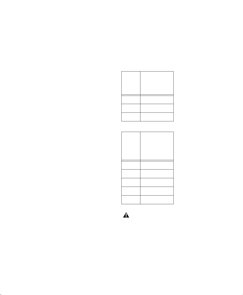
The following tables list the approximate
amount of video storage, in megabytes per second, required for each JFIF compression level.
Storage for Single-Field JFIF
JFIF
level
15:1s .7
4:1s 2.7
2:1s 5.5
Storage Required for Dual-Field JFIF
JFIF
level
30/25 FPS
Storage
(MB/second)
(approximate)
30/25 FPS
Storage
(MB/second)
(approximate,
except 1:1)
Pro Tools AVoption|XL Guide
4
20:1 1.1
10:1 2.2
3:1 7.3
2:1 11
1:1 22
1:1 (uncompressed) data storage levels are
not approximate. The amount of data required to store 1:1 video is always the same,
regardless of the video input used.

Compatibility
Digidesign can only assure compatibility and
provide support for hardware and software it
has tested and approved.
For a list of Digidesign hardware systems,
Digidesign-qualified computers, operating systems, and third-party devices and software, refer
to the latest compatibility information available
on the Digidesign Web site (www.digidesign.com/compato).
Supported Computers
• IBM Z-Pro 6221
• IBM M-Pro 6850
• Compaq Evo 8000
• Power Macintosh G4 with a Digidesign-qualified expansion chassis
• Power Macintosh G3 (Blue & White) with a
Digidesign-qualified expansion chassis
Older G3 Macintosh systems (beige) are not
supported.
Supported Systems
The following Pro Tools TDM systems support
AVoption|XL:
• Pro Tools|HD 6.1, 5.3.3, or 5.3.1 on Windows
XP Professional Edition
• Pro Tools|HD 6.1 on Mac OS X
• Pro Tools|HD 5.3.1 on Mac OS 9.1 or 9.2
• Pro Tools|24 MIX 5.1.3 on Mac OS 9.1 or 9.2
Minimum System Requirements
• Digidesign-qualified computer
• At least 512 MB of RAM
• Digidesign-qualified expansion chassis (required for Macintosh, optional for Windows)
• Digidesign-qualified storage adapters (one for
audio and one for video):
• SCSI HBA: a Digidesign-qualified SCSI HBA
(such as the ATTO UL3D) is required for 1:1
or 2:1 video)
• FireWire (audio only)
• Fiber Channel for Avid Unity™ MediaNetwork or MediaNet
• Power Macintosh 9600 (Pro Tools|24 MIX
5.1.3 only)
Chapter 2: AVoption|XL Hardware Overview
5

3:1 Video Compression or Higher 2:1 Video Compression or 1:1
(Uncompressed)
Minimum AVoption|XL System Requirements
Item Minimum Requirement
Computer IBM Z-Pro 6221 or M-Pro
6850, Compaq Evo
8000,Power Macintosh G4,
Blue & White G3, or 9600
PCI Expansion
Chassis
SCSI accelerator Digidesign-qualified SCSI
SCSI hard drives Digidesign-qualified hard
Striped hard drives Depending on the drive
Avid Unity
MediaNetwork or
MediaNet
(optional)
Sync peripheral SYNC I/O with HD or MIX sys-
Digidesign or Magma 13-Slot
(optional on Windows,
required for Macintosh)
accelerator (such as the ATTO
UL3D); for more information,
see the Digidesign Web site
(www.digidesign.com).
drives are required; for more
information, see the Digidesign Web site (www.digidesign.com).
speed, a 2-way striped or 4way striped drive may be necessary for video playback.
Qualified Fibre Channel PCI
card (ATTO 3300, JNI
FCE3210C, or JNI
FCE3210N).
tems or Universal Slave
Driver (USD) with MIX systems
Minimum AVoption|XL System Requirements
Item Minimum Requirement
Computer IBM M-Pro 6850 or Compaq
8000,Power Macintosh G4,
Blue & White G3, or 9600
PCI Expansion
Chassis
SCSI accelerator
(video)
SCSI accelerator
(audio)
SCSI hard drives Digidesign-qualified hard
Striped hard drives Depending on the drive
Avid Unity
MediaNetwork or
MediaNet
(optional)
Digidesign or Magma 13-Slot
(optional on Windows)
Digidesign-qualified SCSI
accelerator (such as the ATTO
UL3D); for more information,
see the Digidesign Web site
(www.digidesign.com).
Digidesign-qualified SCSI
accelerator (such as the ATTO
UL3D); for more information,
see the Digidesign Web site
(www.digidesign.com).
drives are required; for more
information, see the Digidesign Web site (www.digidesign.com).
speed, a 2-way striped or 4way striped drive may be necessary for video playback.
Qualified Fibre Channel PCI
card (ATTO 3300, JNI
FCE3210C, or JNI
FCE3210N).
Pro Tools AVoption|XL Guide
6
Sync peripheral SYNC I/O with HD or MIX sys-
tems or Universal Slave
Driver (USD) with MIX systems
On Windows with Avid Unity, 1:1 video is
not currently supported with an expansion
chassis.

Synchronization Hardware
Synchronization Peripheral
AVoption|XL requires SYNC I/O for use with
Pro Tools|HD-series systems. AVoption|XL requires Universal Slave Driver (USD) or SYNC I/O
for use with Pro Tools|24 MIX-series and
Pro Tools|24 systems.
SCSI Hardware and Drives with Video Compression Level 3:1 or Higher
If you are using 3:1 video compression or higher
at all times, then your system requires only a
single dual channel SCSI accelerator, with audio
drives connected to one channel and video
drives connected to another. Qualified dual
channel SCSI accelerators (such as the ATTO
UL3D).
Sync Source
For accurate synchronization during capture
and playback, a common video reference is required:
• Black burst
• House Sync source
• Local video source (such as the TBC video output of the machine)
Local Storage Hardware
SCSI Accelerators
To support the high transfer rates required by
AVoption|XL video, a Digidesign-qualified dualchannel SCSI accelerator is required, with audio
drives connected to one channel and video
drives connected to the other channel. For 2:1
compression or 1:1 uncompressed video, two
SCSI accelerators are required.
Using Two Hard Drives
For scenarios that do not require a high audio
track count or a very long video segment, you
may use two hard drives.
In this scenario, one drive is used to record, import, and play back audio data, and the other is
used to do the same for video.
Using More Than Two Hard Drives
To get the highest possible performance from
your AVoption|XL system, you can use more
than two hard drives. In this scenario, you can
use striped hard drives for video data. Striped
volumes appear to AVoption|XL as a single volume.
Striped drives are supported for video only.
Striped drives are not supported for audio.
Audio
AVoption|XL can store audio data to multiple hard drives. You should allocate audio
tracks to different hard drives manually. Round
Robin disk allocation is not recommended in a
system that includes video drives. For more information, see the
Pro Tools Reference Guide
.
Chapter 2: AVoption|XL Hardware Overview
7

Video
AVoption|XL can capture a contiguous
video track to multiple hard disks. This is useful
if the length of your video session exceeds the
storage space available on a single drive. For example, 26 minutes of video material, using 3:1
compression, requires approximately 11.1 GB of
storage space.
4-way striped drives should be connected in
pairs to the video accelerator, with 2 or more
drives connected (in even amounts) to each
channel.
Pro Tools with AVoption|XL does not support striped audio drives for local storage.
SCSI Hardware and Drives with Video Compression Level 2:1 or 1:1
If you are using 2:1 or 1:1 video compression,
your system requires two Digidesign-qualified
SCSI accelerators (such as the ATTO UL3D)—
one for audio and one for video.
Striped Drive Requirements
Striped
drives are configured so that multiple
hard drives behave as if they are one hard drive.
This makes higher data throughput possible. Requirements will vary depending on the drives.
For instance, the 5th-Generation Avid/DigiDrives™ (released November 2001) require 2-way
striped drives when capturing or playing uncompressed (1:1) video. For earlier generations
of drives, 4-way striped drives (4 drives acting as
one) are required when capturing or playing uncompressed (1:1) video. 2-way striped drives (2
drives acting as one) are required when capturing or playing 2:1 compressed video.
For information on Avid Unity MediaNetwork or MediaNet, refer to your Avid documentation.
2-way striped drives should be connected in
pairs to the video accelerator, with 1 drive connected to each channel.
Pro Tools AVoption|XL Guide
8

chapter 3
Installing AVoption|XL
If you do not already have currently supported
Pro Tools hardware installed, you must first install your Pro Tools software and hardware. For
detailed installation information, refer to the
Getting Started Guide
Pro Tools system
Be sure to follow the correct PCI slot placement
of your Pro Tools cards according to the information in Appendix A, “Slot Configurations for
AVoption|XL.”
Once you have installed your Pro Tools system
and verified that it is functioning correctly, proceed by installing the AVoption|XL hardware
and software.
Be sure to install AVoption|XL hardware before
installing AVoption|XL software.
that came with your
.
Installing AVoption|XL Hardware
AVoption|XL PCI Slot
Configurations
To install your AVoption|XL hardware, first determine the PCI slots where you will install the
hardware. For detailed information, see
Appendix A, “Slot Configurations for
AVoption|XL.”
Audio Hardware
Refer to the
your Pro Tools system for audio hardware installation information. You may be required to
move hardware that is already installed to new
PCI slot locations in your computer or expansion chassis, based on the information in
Appendix A, “Slot Configurations for
AVoption|XL.”
Getting Started Guide
that came with
Installing AVoption|XL Video Hardware
To install AVoption|XL video hardware:
1 Unplug and open your computer or expan-
sion chassis according to the instructions included with it.
2 Release any static electricity by touching the
power supply, or another grounded item.
3 Remove the Digital Media Board from the
anti-static bag, being careful to handle it only by
the edges.
4 Locate the PCI slot where you will install the
Digital Media Board. To identify the proper PCI
slot location, see Appendix A, “Slot Configurations for AVoption|XL.”
Chapter 3: Installing AVoption|XL
9
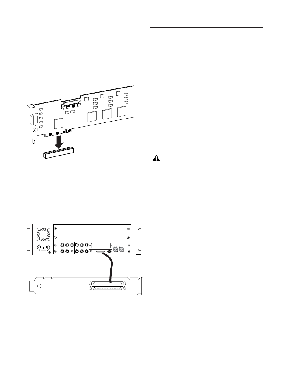
5 Line up the Digital Media Board with the in-
stallation slot, and slide the card into place gently so the PCI connector is lined up with the PCI
slot.
6 Press down firmly on the card with even pres-
sure. The connector should click into place in
the PCI slot.
PCI card alignment and installation
7 Close the computer or expansion chassis.
8 Attach the connector cable from the Digital
Media Board (connector labeled M) to the Computer connector on the AVoption|XL Breakout
Box (see “AVoption|XL Breakout Box” on
page 11).
AVoption|XL Video Connections
The following video I/O capabilities are available with the AVoption|XL Breakout Box:
• Inputs for composite, component (Y, R-Y,
B-Y), S-Video, and (optional) SDI.
• Outputs for composite, component (Y, R-Y,
B-Y), S-Video, and (optional) SDI.
•Video Ref input to allow the video to be
locked to an external source such as house
sync or a blackburst generator.
Note that only one video input source can be
used at a time. For more information, see “Recording Video” on page 25.
The AVoption|XL Breakout Box can only
output from either S-Video or Component
outputs. You must set this option in your
Movie track. See “Setting S-Video or Component Output” on page 26 for instructions.
COMPONENT
COMPOSITE
IN
ININ
Y
R-Y B-Y
IN
S-VIDEO
COMPOSITE
REF
OUT
B-Y
Y
R-Y
OUT 1
OUT 2
SYSTEM
OUT
IN / OUT
S-VIDEO
OUT 3
LTC
IN
OUT
OUT
MC
Connecting the Digital Media Board to the Breakout Box
9 If you need to install a SCSI accelerator card,
do so now (see “Installing the SCSI Accelerator”
on page 18).
Pro Tools AVoption|XL Guide10
AVoption|XL Breakout Box
The following sections provide figures and tables that describe the function of the AVoption|XL
Breakout Box.
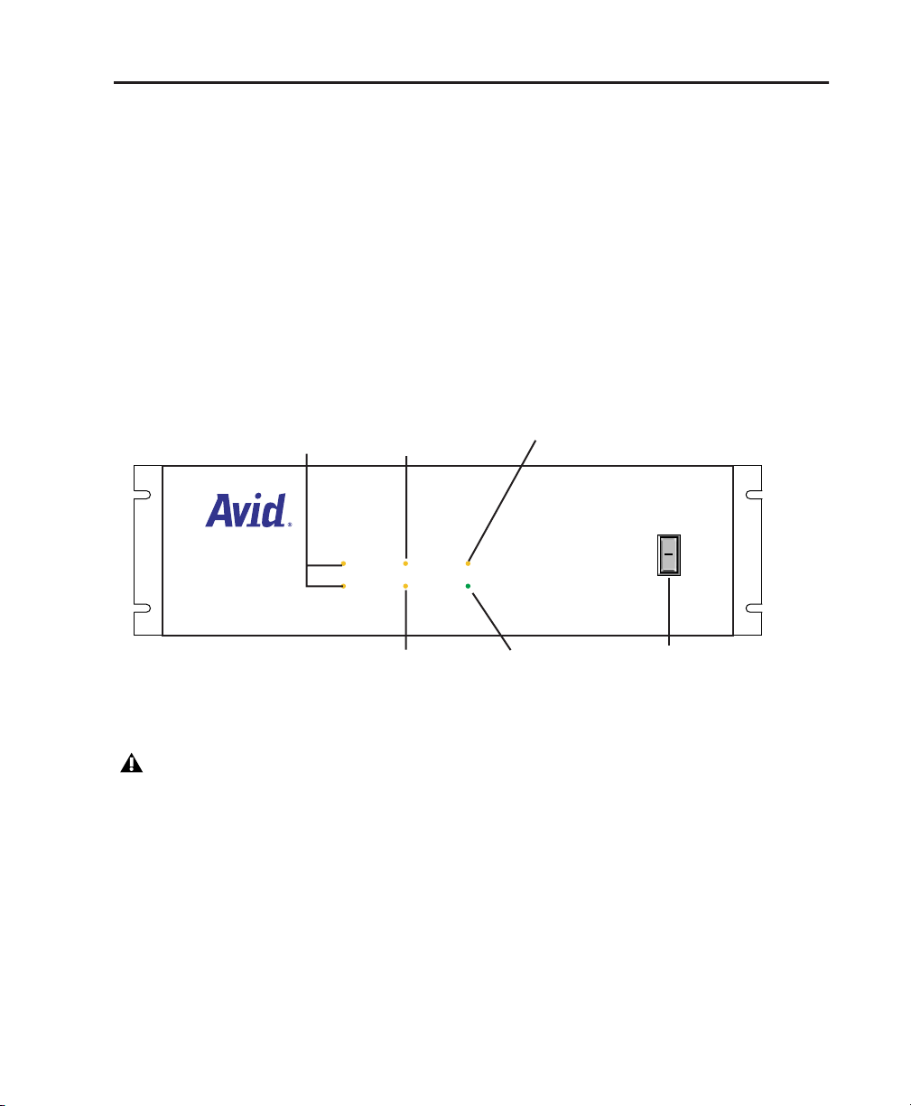
AVoption|XL Breakout Box Front Panel Indicators
The front panel of the AVoption|XL Breakout Box (see Figure 1) has six indicators and a power switch.
When you turn on the AVoption|XL Breakout Box, the indicators turn on and off as it goes through
a power-on self-test (POST). After the POST, the POWER indicator remains lit.
Some indicators do not light, or do not indicate correctly (see illustration). To see the correct indications, use the indicators on your Digidesign SYNC I/O, USD, or the Pro Tools Session Setup window.
44.1 kHz
48
kHz
Audio sync
(this does
not light)
Sample rate
(44.1 or 48
is always lit)
Video sync
Figure 1. AVoption|XL Breakout Box front panel
The sample rate indicator is not accurate
for sessions with sample rates greater than
48 kHz.
AUDIO SYNC
VIDEO SYNC
Pull down
(this does not light)
PULL DOWN
POWER
Power indicator
O
l
Power switch
Chapter 3: Installing AVoption|XL 11
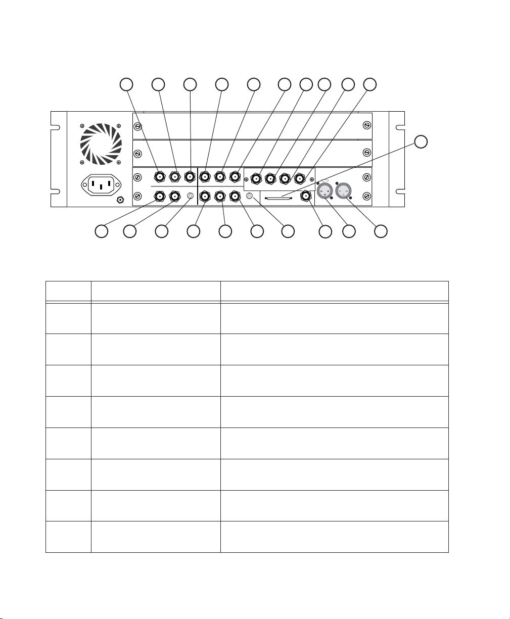
Video I/O Connectors
1 2 3 4 5 6
IN
COMPONENT
IN
COMPOSITE
ININ
Y
R-Y B-Y
S-VIDEO
REF
COMPOSITE
OUT 1
B-Y
Y
R-Y
OUT 3
OUT 2
OUT 1
OUT
SERIAL DIGITAL
OUT
S-VIDEO
20 19 18 17 16 1521 13 12
7 8 9 10
OUT 3IN
OUT 2
SLAVE CLOCK
SYSTEM
IN / OUT
OUT
14
LTC
OUT
IN
Figure 2. AVoption|XL Breakout Box back panel showing video connectors
Table 1. Video I/O Board Identifiers
Number Label Function
1 COMPONENT Y IN Video Y component input, BNC connector. Connects to ana-
log video output of decks.
2 COMPONENT R-Y IN Video R-Y component input, BNC connector. Connects to
analog video output of decks.
3 COMPONENT B-Y IN Video B-Y component input, BNC connector. Connects to
analog video output of decks.
11
4 COMPONENT Y OUT Video Y component (Betacam) output, BNC connector. Con-
nects to analog video input of decks.
5 COMPONENT R-Y OUT Video R-Y component (Betacam) output, BNC connector.
Connects to analog video input of decks.
6 COMPONENT B-Y OUT Video B-Y component (Betacam) output, BNC connector.
Connects to analog video input of decks.
7 SDI IN (optional) Serial digital input, BNC connector. Connects to a serial dig-
ital output from a digital video source.
8 SDI OUT1 (optional) Serial digital output number 1, BNC connector. Connects to
VTR input, a video monitor, or other serial digital device.
Pro Tools AVoption|XL Guide12

Table 1. Video I/O Board Identifiers(Continued)
Number Label Function
9 SDI OUT2 (optional) Serial digital output number 2, BNC connector. Connects to
VTR input, a video monitor, or other serial digital device.
10 SDI OUT3 (optional) Serial digital output number 3, BNC connector. Connects to
VTR input, a video monitor, or other serial digital device.
11 SYSTEM Audio and video I/O connector from the system interface
board.
12 LTC OUT Sends LTC time code out (not used).
13 LTC IN Brings LTC time code in (not used).
14 SLAVE CLOCK OUT Clock output, BNC connector (not used)
15 S-VIDEO OUT Super-video output, 4-pin connector. Connects to analog
video input of decks.
16 COMPOSITE OUT3 Composite video output, BNC connector. Connects to analog
video input of decks or monitor.
17 COMPOSITE OUT2 Composite video output, BNC connector. Connects to analog
video input of decks or monitor.
18 COMPOSITE OUT1 Composite video output, BNC connector. Connects to analog
video input of decks or monitor.
19 S-VIDEO IN Super-video input, 4-pin connector. Connects to analog video
output of decks.
20 COMPOSITE IN Composite video input, BNC connector. Connects to
analog video output of decks.
21 Video Reference (REF) Blackburst or house sync input, BNC connector. Synchro-
nizes the system with the global clock source provided by the
house sync or blackburst generator.
Chapter 3: Installing AVoption|XL 13

SYNC I/O Connections
5
The following illustrations show SYNC I/O connections for Pro Tools|HD and Pro Tools|24 MIX
systems with AVoption|XL. The SYNC I/O Guide
provides more specific information about this
peripheral.
House Video
Reference
VIDEO REF
Serial cable
to computer
HOST SERIAL
SYNC I/O video connections
from Loop Sync Out
(audio interface)
IN
9-PIN OUT 1
OUT
x)
9-PIN OUT 2
to Loop Sync In
(HD audio interface)
SYNC I/O connection to a Pro Tools|HD audio interface
VTR out
IN
OUT
VIDEO
to COMPOSITE VIDEO
AC 100-240V, 50-60HZ, .5A 30W
LOOP SYNC
INTERNALLY
TERMINATED
MTC OUT
USD Connections
(Pro Tools|24 MIX or Pro Tools|24 Systems
Only)
The following illustrations show USD connections. The Universal Slave Driver User’s Guide provides more specific information about this peripheral.
House Video
Reference
VIDEO REF
Serial cable
to computer
MAC SERIAL
VTR out
IN
OUT
VIDEO
to COMPOSITE VIDEO
USD video connections
85-264VAC, 47-63HZ, 115 W
9-PIN IN / ACC
9-PIN OUT
IN
OUT
SUPER CLOCK (256X)
to Slave Clock In
(audio interface)
USD connection to an audio interface
Connecting House Video Reference or Blackburst
IN
OUT
WORD CLOCK (1x,256x)
to Slave Clock In (x256)
9-PIN OUT 1
9-PIN OUT 2
(MIX audio interface)
IN
OUT
LOOP SYNC
AC 100-240V, 50-60HZ, .
SYNC I/O connection to a Pro Tools|24 MIX audio
interface
Pro Tools AVoption|XL Guide14
In most AVoption|XL setups, three blackburst or
house video reference (house sync) connections
are required:
•To VIDEO REF IN on the SYNC I/O or USD
•To a video input on your VTR (a video reference input if available)
•To the VIDEO REF connector on the AVoption|XL Breakout Box
Read the documentation for your blackburst
generator for more information.

Connecting a VTR
A VTR can be used to provide video input and to
record video output from AVoption|XL. In most
situations, there are three connections you need
to make:
• Connect a blackburst or house sync output to
a video input on your VTR (preferably a reference video input).
• Connect the AVoption|XL Breakout Box Composite IN, Component IN, S-Video IN, or SDI
IN connectors to the corresponding output or
outputs on your VTR.
• Connect the AVoption|XL Breakout Box Composite OUT, Component OUT, S-Video OUT,
or SDI OUT connectors to the corresponding
inputs on your VTR.
– or –
• Connect the AVoption|XL Breakout Box Composite OUT or Component OUT connectors
to the corresponding input on an NTSC or
PAL video monitor, then connect the outputs
from this monitor to the corresponding inputs on your VTR.
The AVoption|XL Breakout Box can only
output from either S-Video or Component
outputs (S-Video is a type of Component
output and you must choose which component output you want to use). You must set
this option in your Movie track. See “Setting
S-Video or Component Output” on page 26
for instructions.
Connecting an External Video Reference Monitor
Connect an external NTSC or PAL video reference monitor to a Composite, Component, SVideo, or SDI output.
Centralized Video Switching and Routing
Many professional facilities have centralized
video switching and routing systems. These systems can be used to route AVoption|XL inputs
and outputs to flexible input sources and output
destinations.
Starting Up Your System
To ensure that the components of you Pro Tools
AVoption|XL system communicate properly
with each other, you need to start up your system in the correct order.
Start up your Pro Tools AVoption|XL system in the
following order:
1 Turn on the Expansion Chassis, if any.
2 Turn on any external hard drives.
3 Turn on the SYNC I/O or USD.
4 Turn on the Pro Tools audio interfaces.
5 Turn on the AVoption|XL Breakout Box.
6 Start up your computer.
For professional quality video layback, export audio from Pro Tools and import it
into an Avid workstation with the video
track. You can also layback the audio to
video tape.
Chapter 3: Installing AVoption|XL 15

Installing AVoption|XL Software
To install AVoption|XL software on Windows:
1 Start your computer and log on to Windows
with Administrator privileges.
2 Wait for the Found New Hardware Wizard di-
alog to appear and leave it open.
3 Leaving the Found New Hardware Wizard di-
alog open, insert the AVoption|XL Installer CDROM in your computer’s CD-ROM drive. Locate
and launch the Setup.exe file.
4 Click Next.
5 Click Yes.
6 Wait for the installer to finish installing all
software components. When installation is
complete, click Finish to restart your computer.
To install AVoption|XL software on Macintosh:
1 Start your computer. If you are running Mac
OS X, be sure to log on with Administrator privileges.
2 Insert the AVoption|XL Installer CD-ROM in
your computer’s CD-ROM drive.
3 Locate and launch the AVoption|XL Installer
file.
4 Follow the on screen instructions to install the
AVoption|XL software.
5 When the installation is complete, quit the in-
staller and restart your computer.
Authorizing AVoption|XL
Once you have installed your AVoption|XL software and hardware, launch Pro Tools to authorize AVoption|XL using the iLok USB Smart Key
and the licence card (see “iLok” on page 16), or
the authorizer key disk (see “Key Disk Authorization” on page 17).
iLok
AVoption|XL is authorized using the iLok USB
Smart Key from PACE Anti Piracy. One iLok USB
Smart Key is included with Pro Tools HD Core
systems. This key can hold over 100 authorizations for all your iLok-enabled software. Once a
software authorization is added to an iLok USB
Smart Key, you can use the iLok to authorize
that software on any computer.
Authorizations are added to an iLok using License Cards that have a small punch-out GSM
plastic chip. License Cards are specific to each
Pro Tools option or plug-in you purchase.
To add an authorization to an iLok:
1 Insert the iLok USB Smart Key into an avail-
able USB port on your computer.
2 Launch Pro Tools. You will be prompted to au-
thorize AVoption|XL.
3 Follow the on-screen instructions until you
are prompted to insert the License Card into the
iLok USB Smart Key.
4 Separate the License Card from the larger pro-
tective card by pulling the cutout up and out
with your thumb.
Pro Tools AVoption|XL Guide16

5 Insert the License Card into the iLok. You will
be able to visually verify that the License Card
makes contact with the iLok’s metal card reader.
iLok USB Smart Key with License Card
6 With the iLok USB Smart Key inserted in any
available USB port on your computer, click Authorize.
7 After authorization is complete, remove the
License Card from the iLok USB Smart Key. (If
you have to remove the iLok USB Smart Key to
remove the License Card, be sure to re-insert the
iLok USB Smart Key in any available USB port on
your computer.)
Key Disk Authorization
(Pro Tools 5.1.3 Only)
To authorize or deauthorize AVoption|XL:
1 Insert the Authorizer diskette into the floppy
drive. (Pro Tools should NOT be launched during this process).
2 Click Authdeauthorizer in the pop-up win-
dow that appears.
3 Click Set-up Authorizer or Deauthorizer.
4 Choose Authorize or Remove. (If you are re-
moving an authorization and a “?” appears over
the application icon, the diskette you inserted is
not the one you originally used for the authorization. You should see a gold key icon. If you
continue through the deauthorization process
with a “?”, the application will be deauthorized,
but an authorization will not credited back to
the diskette for your next installation.)
5 Select disk location and click Authorize or Re-
move.
6 Quit.
You can also use an Authorizer diskette to authorize or deauthorize AVoption|XL. After you
install the software from the CD-ROM, the Authorizer diskette permits you to authorize and
use a single copy of AVoption|XL.
AVoption|XL software is installed in a specific
location on your hard drive, and should not be
moved or altered. The Authorizer diskette permits you to reclaim authorization from your
hard drive if you want to install AVoption|XL on
a different hard drive, or if you want to re-initialize or format your drive.
Chapter 3: Installing AVoption|XL 17

Using NTSC and PAL
When switching between NTSC and PAL formats, settings must be changed in three places:
• In the Pro Tools Session Setup window, select
the correct frame rate from the Frame Rate
pop-up menu (25 FPS, 29.97 FPS, or 29.97 FPS
Drop).
• In the Session Setup window, the SYNC I/O or
USD must be set to the correct format (PAL or
NTSC).
When a video clip is imported to the Movie
track, Pro Tools 5.3.1 or later sets the correct format (PAL or NTSC) on the SYNC I/O
automatically.
• If you are going to capture video with AVoption|XL, select the correct video format (PAL
or NTSC):
• In Pro Tools 5.3.1 on Windows or Pro Tools
5.1.3 on the Macintosh, click the Track Options button on the Movie track and select
the correct video format (PAL or NTSC)
from the Video Format pop-up menu (see
Figure 3 on page 23). This setting can be
modified when the Movie track is armed
for record.
– or –
• In Pro Tools 5.3.3 or later on Windows or
Pro Tools 5.3.1 or later on Macintosh, select the correct video format (PAL or NTSC)
from the Video Format pop-up menu in the
Session Setup window.
• If you import an existing video file to the
Movie track, the Video format is set automatically to NTSC or PAL according to the first
frame of the imported video.
Installing the SCSI Accelerator
To install a SCSI Accelerator card:
1 Unplug and open your computer or expan-
sion chassis according to the instructions included with it.
2 Release any static electricity by touching the
power supply, or another grounded item.
3 Remove the SCSI accelerator card from the an-
tistatic bag, being careful to handle it only by
the edges.
4 Line up the SCSI accelerator card with the in-
stallation slot, and slide the card into place gently so the PCI connector is aligned with the PCI
slot.
If installing the SCSI accelerator card in
your computer, always install it in the highest numbered slot available. If installing the
SCSI accelerator card in an expansion chassis, see Appendix A, “Slot Configurations
for AVoption|XL” to determine the correct
slot placement
5 Press down firmly on the card with even pres-
sure. The connector should click into place in
the PCI slot.
6 Fasten the card in place using the included
screw to attach the card bracket to the computer
mounting bracket.
Pro Tools AVoption|XL Guide18

Updating the SCSI BIOS
(Windows Only)
When starting your computer, you will see
which version of the ATTO SCSI BIOS is installed on the ROM of the ATTO SCSI card. If it
is not version 1.6.6 or higher , you will need to
flash the SCSI BIOS with 1.6.6 or higher ATTO
SCSI BIOS. If the ATTO SCSI BIOS is already at
version 1.6.6, proceed to installing the Windows
device driver (see “Installing the Windows Device Driver” on page 19).
Installing the Windows Device Driver
(Windows Only)
Verify that the ATTO SCSI BIOS is version 1.6.6
or higher. If it not, you will need to update the
SCSI BIOS (see “Updating the SCSI BIOS” on
page 19).
To install the ATTO Windows device driver:
1 Start up your computer. Note the version of
the ATTO SCSI BIOS when booting.
To update the BIOS on the ATTO SCSI card:
1 Insert a High Density PC formatted floppy
disk.
2 Copy the DOS folder from the ATTO folder on
the AVoption|XL Installer CD-ROM to the
floppy disk.
3 Shut down your computer.
4 Disconnect any hard drives connected to the
SCSI card.
5 Boot your computer with the floppy disk in
the floppy drive.
6 When prompted, press Control+Z.
7 Press Enter.
8 Select Adapter Menu.
9 Select Update Flash ROM.
10 Press Enter twice.
The SCSI BIOS will be updated. This may take a
few minutes.
11 Select Configure Adapter Channels.
12 Set Host Adapter BIOS to Scan Only.
13 Press the Esc key twice.
14 Select Save Parameters and Exit, and press
Enter.
2 Insert the AVoption|XL Installer CD-ROM.
3 Launch the System control panel.
4 Select the Hardware tab.
5 Click Device Manager.
6 Select SCSI and RAID controllers.
7 Double-click the LSI PCI SCSI Adapter.
8 Select the Driver tab.
9 Click Update Driver.
10 Select “Install from specified location.”
11 Select “Don’t search, I’ll choose the driver to
install.”
12 Click Next.
13 Click Have Disk.
14 Click Browse and navigate to the ATTO
folder on the AVoption|XL Installer CD-ROM.
15 Select EXPRESS.INF and click Open.
16 Click OK.
17 Click Next.
18 Click Finish.
19 Click Close.
Chapter 3: Installing AVoption|XL 19

20 If you have a dual-channel SCSI card, repeat
steps 7–19 for the second channel.
21 Click OK.
Formatting Hard Drives
(Windows Only)
On Windows, format your video and audio hard
drives as NTFS or FAT32 with 32k clusters using
Windows Disk Administrator or PartitionMagic.
Striped drives are supported for video, but not
for audio.
• UL3D with HD hardware: “160 (80)”
(160 MB/sec at 80 MHz)
• EPCI-DC, SCSI64, EPCI-UL2D or EPCIUL3D with MIX hardware: “20 (10)”
(20 MB/sec at 10 MHz)
4 From the PCI Burst Rate pop-up menu, select
the correct setting for your setup:
• EPCI-DC, SCSI64 with HD hardware: “32”
• UL2D with HD hardware: “128”
• UL3D with HD hardware: “128”
• EPCI-DC, SCSI64, EPCI-UL2D or EPCIUL3D with MIX hardware: “32”
Flashing the ATTO HBA NVRAM
Mac OS 9
ExpressPro-Tools is supplied with Pro Tools 5.1
or later and every ATTO SCSI card. It allows you
to flash the ROM on the SCSI card. Digidesign
strongly recommends that the firmware be set
on SCSI channels where audio storage is connected.
These settings are optimized for the size and frequency of SCSI transactions demanded by
Pro Tools. If you have a dedicated SCSI card for
video media, you do not need to apply these settings to it.
To update the ATTO host bus adapter firmware
using ExpressPro-Tools:
1 Launch ExpressPro-Tools after booting your
system and mounting all drives.
2 Double-click Media Drive.
3 From the Sync Rate pop-up menu, select the
correct setting for your setup:
• EPCI-DC, SCSI64 with HD hardware: “20
(10)” (20 MB/sec at 10 MHz)
• UL2D with HD hardware: “80 (40)”
(80 MB/sec at 40 MHz)
5 Click “Apply to All” (sets the card for all drive
IDs on that bus).
6 Repeat if necessary for the other bus.
7 Quit ExpressPro-Tools.
8 Restart you computer.
Mac OS X
ATTO Configuration Tool is supplied with
Pro Tools 6.0.1 or later and every ATTO SCSI
card. It allows you to flash the ROM on the SCSI
card. Digidesign strongly recommends that the
firmware be set on SCSI channels where audio
storage is connected.
To update the ATTO host bus adapter firmware
using ATTO Configuration Tool:
1 Start up your computer.
2 Insert the Pro Tools Installer CD-ROM.
3 Locate and launch the ATTO Configuration
Tool installer (in Pro Tools Installer/ATTO Utilities/ATTO Configuration Tool). Follow the onscreen instructions to install the application and
drivers.
4 After installing the ATTO Configuration Tool,
restart you computer.
Pro Tools AVoption|XL Guide20

5 Locate and launch the ATTO ExpressPCI ap-
plication (in Applications/ExpressPCI Configuration Tool).
6 In the left pane, expand hosts to localhost:Ex-
pressPCI.
7 Select the ExpressPCI.
used to initialize all audio and video drives on
Mac OS 9. Both HFS and HFS+ file systems are
supported for audio drives on Mac OS 9 (HFS+ is
recommended). On Mac OS X, use the Apple
Disk Utility to format your drives Mac OS Extended. Select the Install Mac OS 9 Drivers option for compatibility with Mac OS 9 systems.
8 In the right pane, click the Flash tab. The Flash
options appear.
9 Click Browse and navigate to ATTO Utili-
ties/ATTO Firmware Images on the Pro Tools Installer CD-ROM.
10 Select the appropriate firmware image (either
the UL3D or EPCI-DC).
11 Click Update. A message box appears telling
you to unmount all devices.
12 Click OK. The firmware updates. The update
is finished when a message appears at the bottom of the ATTO Configuration Tool window.
13 Close all the open windows.
14 Restart your computer.
Initializing Hard Drives
(Macintosh Only)
The following is hard drive initialization information for three different scenarios: Pro Tools
with no interchange, Avid to Pro Tools, and
Pro Tools to Avid.
Pro Tools and AVoption|XL do not support
striped audio drives, but they do support
stripped video drives.
Pro Tools with No Interchange
In installations where Pro Tools will not be routinely sharing projects with Avid Media Composer systems, ExpressPro-Tools from ATTO
(provided with Pro Tools 5.1 or later) should be
Avid to Pro Tools
For projects originating on an Avid Picture Authoring system, such as Media Composer, a single HFS drive initialized with either Avid Drive
Utility (ADU) 2.1 or later is supported. This drive
may contain either video or audio media files, or
both. Pro Tools with AVoption|XL supports
playback of audio and video tracks from a single
drive, as long as track count does not exceed one
stream of video (at a compression of 3:1 or
higher) and a maximum of eight audio tracks.
When this drive is used in a Pro Tools session,
additional audio tracks (beyond those imported
from the Avid workstation) should not be
added, for bandwidth reasons.
Video-only drives initialized as 2-way or 4-way
stripe sets by Avid Drive Utility 2.1 (or later) are
also supported. It is recommended that video
drives be added to the SCSI channel dedicated
for video in order to balance demands on the
SCSI bus.
Pro Tools can only recognize a maximum
seven drives per SCSI channel.
Pro Tools to Avid
When a drive is being sent from a Pro Tools system to an Avid picture workstation, the drive
should be initialized as HFS or HFS+ using ExpressPro-Tools on Macintosh. When an Avid
Chapter 3: Installing AVoption|XL 21

system is inheriting files from Pro Tools, a
“finder copy” of these files may be necessary to
transfer them from the Pro Tools drive to a drive
the Avid workstation will recognize.
If a drive is moved from a Pro Tools system to an
Avid workstation, so that files from the Avid system can be copied and returned to the Pro Tools
system, the drive should be initialized as HFS or
HFS+ using ExpressPro-Tools on Mac OS 9 (HFS+
is recommended), or Mac OS Extended using
the Apple Disk Utility on Mac OS X, before being mounted on the Avid workstation.
When formatting DigiDrives over 60 GB for
use with Macintosh, it is recommended that
you format the drives HFS+ rather than
HFS. However, if you wish to format a drive
HFS, you should partition the drive using
partitions that are less than 69,695 MB.
Special Configuration Requirements
When you want compression levels of 2:1 or 1:1
(uncompressed), a second accelerator must be
dedicated to video storage. Depending on your
drives’ performance, a 2-way stripe set across
both SCSI channels may be required for 2:1 capability, and a 4-way stripe across both channels
may be required for 1:1 (uncompressed) capability. Newer SCSI drives, like the 5th-Generation
Avid/DigiDrive can record and play back 2:1
video from a single drive, and 1:1 video from a
2-way stripe set. It is not necessary to use stripe
sets for 3:1 or higher.
To initialize hard drives on Mac OS:
1 Select the drives you want to dedicate to video
and create your stripe set (if desired) by doing
one of the following:
• On Mac OS X, initialize video drives using
the ATTO ExpressStripe utility (optional
software available from ATTO).
• On Mac OS 9, initialize video drives using
the ATTO ExpressRAID utility (optional
software available from ATTO).
2 Select the drives you want to dedicate to audio
and do one of the following:
• On Mac OS X, initialize all audio drives using the Apple Disk Utility.
• On Mac OS 9, initialize all audio drives using ATTO ExpressPro-Tools (provided on
the AVoption|XL Installer CD-ROM).
Do not use ExpressRAID to initialize your
audio drives. ExpressRAID is not supported
with audio drives.
Media Management
It is recommend that you dedicate one SCSI
channel to audio drives and one SCSI channel to
video drives. This configuration is adequate for
AVoption|XL with compression levels of 3:1 or
higher.
If you want compression levels of 2:1 or 1:1 (uncompressed), an additional dual-channel SCSI
card is required for video drives.
If your Pro Tools system is mounting a drive initialized by an Avid picture workstation that contains video files, it is recommended that this
drive be installed on the SCSI bus dedicated to
video data.
If your Pro Tools system receives a drive initialized by an Avid picture workstation, it is recommended that you do not record additional audio
files onto this drive.
Pro Tools AVoption|XL Guide22

chapter 4
Recording and Adding to the Movie Track
You can capture video files by recording the
video through the inputs on your AVoption|XL
Breakout Box. You can also import files captured
with another Pro Tools system or created in a
compatible Avid video workstation.
The Movie Track
The Movie track holds the video clips you capture or add into Pro Tools. A Pro Tools session
can only contain one Movie track.
To create a new Movie track:
■ Choose Movie > New Avid Movie Track (New
Movie Track in Pro Tools 6.0 or lower).
The new, empty Movie track appears in the Edit
window.
To name the Movie track:
1 Double-click the Track Name button to open
the Name and Comments dialog.
2 Type a name (and any optional comments),
then click OK.
To select a compression ratio:
1 Select Display > Edit Window Shows I/O view.
2 Record enable the Movie track.
3 Select a compression ratio from the Compres-
sion Level pop-up menu (see Figure 3).
Track
Height
Compression
Level
1st video record drive
2nd video record drive
3rd video record drive
Approximate available
record time
Track
Options
AVoption|XL
Breakout Box
inputs for
recording
Video Output
format
Record
View
Options
Track Name
Figure 3. Movie track controls
To select record drives:
1 Select Display > Edit Window Shows I/O view.
2 Select video record drives from the three Avid
Video Drives pop-up menus (see Figure 3).
In Pro Tools 5.3.1 on Windows and
Pro Tools 5.1.3 on Macintosh, the Video
Format pop-up menu is located in the Movie
track’s Track Options pop-up menu.
Chapter 4: Recording and Adding to the Movie Track 23

To delete the Movie track:
1 Select the track by clicking the Track Name
button in the Edit window.
2 Choose File > Delete Selected Tracks.
Frames do not display properly if you change
zoom settings during playback. Black frames are
drawn until playback is stopped. You should
stop playback before changing zoom settings if
you want to view frames.
To clear all video from the Movie track:
■ Choose Movie > Clear Movie Track.
You cannot change names of clips after they
have been added or recorded. When added, clips
retain the name they were given by the original
workstation. When recorded in Pro Tools, the
clip name is derived from the Movie track’s
name. You can change the name of a new clip
by renaming the Movie track.
Movie Track Options
The Movie track can be viewed in frames or in
blocks. Frames allow you to see an overview of
the actual video content in a session. Blocks allow you to see where clips begin and end, and
the names of clips.
Frames
In Frames mode, video data is displayed as pictures in the Movie track. These pictures are computed based on the video image, and scale according to your track zoom and height settings.
They do not provide a frame-accurate reference,
but allow you to easily find a scene or sequence
in the Movie track.
If video pull-up or pull-down is enabled,
Frames do not change position and are
therefore not a useful reference.
Blocks
Blocks mode displays the Movie track as blocks
of compositional data. Blocks are outlined wherever clip boundaries exist. These block names
indicate both the boundaries for clips defined in
a video editing system and separate clips recorded into Pro Tools. Names from the original
clips are retained, and new names are given to
newly recorded material. For example, two clips
edited together without any transitions or effects, and named “House Ext” and “House Int,”
will appear as two blocks bordering each other
with those names.
Movie track in Blocks mode
In Blocks mode, you can place the cursor on the
Movie track, then press Tab to move to the next
video edit in the track.
To set the view for the Movie track:
■ On the Movie track, select Frames or Blocks
from the View Options pop-up menu.
Movie track in Frames mode
Pro Tools AVoption|XL Guide24
When switching from Blocks mode to
Frames mode during playback, the movie
track will not update to displaying frames
until playback is stopped.

Recording Video
You can record multiple video clips to multiple
locations on a single Movie track.
To set video recording options:
1 Choose Movie > New Avid Movie Track (New
Movie Track in Pro Tools 6.0 or lower) to create
a new Movie track.
2 Select Display > Edit Window Shows I/O view.
3 In Pro Tools 5.3.3 or later on Windows, or
5.3.1 or later on Macintosh, select NTSC or PAL
from the Video Format pop-up menu in the Session Setup window (Windows > Session Setup).
4 Select the video input from the Movie Track
Options pop-up menu (Component or Composite input, or S-Video or SDI).
5 Set the compression level for the video cap-
ture from the Compression Level pop-up menu.
6 Select the target hard drive volumes for the
video capture. Target volumes capture video in
order, from the first (top) to the last (bottom). In
the following illustration, Video 1 captures
video first, followed by Video 2, then Video 3.
Avid Video Drive
pop-up menus
Selecting drives for video capture
As you add or remove volumes from the track,
the available record time is updated to reflect
available disk space and compression settings.
The time displayed is approximate.
Video Format pop-up menu, Session Setup window
Using Pro Tools 5.3.3 or later on Windows,
or 5.3.1 or later on Macintosh, if you import
an existing video file to the Movie track, the
Video format is set automatically to NTSC
or PAL according to first frame of the imported video.
– or –
In Pro Tools 5.3.1 on Windows, or 5.1.3 on Macintosh, select a video format by clicking the
Movie track’s Track Options button, and then
select NTSC or PAL Video Format.
In Pro Tools 5.3.1 on Windows and
Pro Tools 5.1.3 on Macintosh, the Video
Format pop-up menu is located in the Movie
track’s Track Options pop-up menu.
To record video:
1 Use your cursor to mark the point from where
you want to start recording.
– or –
Make a selection on a Timebase Ruler or on a
track to select a range of time for the recording.
To make selection on a track, Operations > Link
Edit and Timeline Selection must be enabled.
2 Record enable the Movie track by clicking the
Record Enable button.
3 Click the Record button in the Transport win-
dow to enable recording.
4 Start playing the video source.
5 Click Play in the Transport window to begin
recording.
Chapter 4: Recording and Adding to the Movie Track 25

6 Click Stop in the Transport window to stop re-
cording.
If there are already clips on the Movie track,
and you record over them, the overwritten
material will be removed from the Movie
track (although it will still remain intact in
its original storage location).
Capture Clip and restore the original clips.
For more information, refer to “Undo/Redo
for Video Editing Commands” on page 29.
Ctrl+period (Windows) or Command+period (Macintosh) will abort a clip capture in
progress and restore the Movie track to the
original clips.
You can Undo
Capturing and Approximate Time Left
The Approximate Record Time Left in the I/O
View of the Movie track is an estimate. AVoption|XL uses variable compression technologies,
and record time varies based on the density of
the material you are recording. The Approximate Record Time Left is intended to provide
you a rough estimate and may not be an accurate reflection of your available record time.
The calculation of Approximate Record Time
Left is a conservative estimate based on the
highest data rate possible for that resolution.
The approximation may vary by several minutes.
Pro Tools uses the Approximate Record Time
Left value to allocate drive space before recording. Because of the approximate nature of the
estimation process, you may find that you have
available record time left after you thought you
had filled the drive.
The Record Time Left value is not approximate if you are capturing video at a compression rate of 1:1 (uncompressed) in
AVoption|XL. Since this video is uncompressed, it uses the same data rate, regardless of the image.
Timebase Correction
AVoption|XL requires that all sources be timebase corrected.
have built-in timebase correction. To find out
whether or not your video deck has built-in
timebase correction, refer to the manufacturer’s
documentation.
Most professional video decks
Setting S-Video or Component Output
The AVoption|XL Breakout Box can output from
either the S-Video or Component outputs. Composite out is always active regardless of whether
S-video or Component is selected. This selection
must be made in Pro Tools, and will determine
which physical connections you use to output
signals.
To select component video outputs in
AVoption|XL:
1 On the Movie track, click the Track Options
pop-up menu (see Figure 3 on page 23).
2 Use the Video Output pop-up menu to select
the desired outputs: Component or S-Video.
Pro Tools AVoption|XL Guide26

MachineControl
You can use Digidesign MachineControl software to remotely control your external video
deck during Pro Tools capture. Blocks mode is
recommended when recording to the Movie
track with MachineControl. MachineControl is
a Pro Tools software option that can be purchased separately.
For more information, see the MachineControl Guide.
Exporting Files from Avid Programs
If you already have a project that was created on
an Avid video authoring system, you can export
it to an AAF (Pro Tools 6.1 only) or OMFI 2.0 sequence so the material can be added into your
AVoption|XL system. This exchange of data between systems is significantly faster and easier
than other methods, such as laying off to tape
and re-digitizing.
When an AAF or OMF sequence exported from
an Avid workstation is imported into Pro Tools,
the video track displays each of the video files as
regions in the timeline. Generally, these regions
reflect the regions on the Avid timeline, unless
you have an effect which spans more than one
video clip.
All video effects, including fades, must be ren-
dered before they can be exported in an AAF or
OMF sequence. Rendering means that a media
file called a “precompute” is created. This precompute is what is exported and what appears
in the Pro Tools timeline. For example, if there
are three video clips in the Avid timeline and a
title effect is laid across all three, the title would
have to be rendered before export, creating a
single precompute file. Then, instead of seeing
the three original video clips in the Pro Tools
timeline, only the one precompute clip will be
displayed.
DigiTranslator 2.0 Integrated Option
DigiTranslator 2.0 is included with your AVoption|XL package. Use DigiTranslator to convert
AAF sequences (Pro Tools 6.1 only) and OMFI
sequences and media files into Pro Tools session
files. You can also use it to export audio material
from Pro Tools sessions to AAF sequences
(Pro Tools 6.1 only) or OMFI sequences and files
for import into other systems.
For more information, refer to the Digi-
Translator 2.0 Integrated Option Guide
Avid Unity
Pro Tools with AVoption|XL supports Avid
Unity™ MediaNetwork or Media Net, and Media Manager. Avid Unity MediaNetwork and
MediaNet provide integrated high-speed network storage systems for Avid (Media Composer®, Symphony™, Avid Xpress®, and NewsCutter®) and Pro Tools workstations.
MediaManager is an Avid database product for
tracking files on a MediaNetwork or MediaNet
system. For detailed information on configuring
your Pro Tools system with AVoption|XL as an
Avid Unity MediaNetwork or MediaNet client,
refer to Avid Unity MediaNetwork or
MediaNet documentation.
.
Chapter 4: Recording and Adding to the Movie Track 27

Multi-Streams and AVoption|XL
While some Avid systems support simultaneous
streams of real time video, AVoption|XL supports only one stream. For this reason, it is necessary to make sure that all multi-stream transitions and effects are rendered in the Avid
sequence before you export.
If you add a sequence into Pro Tools that includes multi-stream effects, black frames will be
substituted in their place.
AVoption|XL does not require the entire sequence to be rendered into one continuous clip
(often referred to as a “video mixdown”). AVoption|XL can import and play sequences containing multiple single-stream clips.
Avid Multi-Cam Resolution Files
AVoption|XL supports all Avid Multi-Cam Resolution files for import and playback, but not for
capture. Pro Tools will play the clip of an Avid
Multi-Cam Resolution file that was being used
as the main camera angle when the file was exported to an AAF or OMFI file.
Exporting from Media Composer
This section uses a Media Composer project as
an example.
To export an AAF or OMFI sequence with external
media from Media Composer:
1 Select the sequence.
2 Choose Edit > Duplicate to make a copy of the
sequence, so the original remains intact.
3 As desired, choose Clip > Consolidate to place
a copy of the relevant media files (both audio
and video) in a single hard drive location.
4 Choose File > Export. In the Export dialog, se-
lect AAF or OMFI Composition with the following options:
• For the OMFI file type, select Standard-AIFC.
•To specify which data is exported, select Video
and Audio.
• For the OMFI version, select OMFI 2.0 and
make sure With Media is deselected.
5 Click OK to export an OMFI file that will ref-
erence external media files.
To export an OMFI sequence with embedded
media from Media Composer:
1 Choose Edit > Duplicate to make a copy of the
sequence you are working with, so the original
remains intact.
Consolidating also ensures that only the media
used in the sequence is exported and embedded
with the OMFI file.
To prepare a Media Composer project for AAF or
OMF export and use with AVoption|XL:
■ Make sure all media for the project is online.
■ Render all effects in advance. AAF or OMF ex-
port does not automatically render effects during the process, so if you want to see them, you
must render effects before you export.
Pro Tools 5.x does not support import of
AAF sequences.
Pro Tools AVoption|XL Guide28
2 Choose File > Export. In the Export dialog, se-
lect OMFI Composition with the following options:
• For the OMFI file type, select StandardAIFC.
•To specify which media is exported, select
Audio Only.
Pro Tools supports embedded audio, but
not embedded video.

• For the OMFI version, select OMFI 2.0 and
make sure With Media is selected.
3 Click OK to export an OMFI file with the au-
dio media embedded. All audio contained in the
OMFI file is written in the selected audio format.
Adding OMFI Video Clips
Using the Add Avid Movie command (Add
Movie in Pro Tools 6.0 and 5.x), you can add
several clips to a single Movie track.
If there are already clips on the Movie track and
you add over them, the overwritten material
will be removed from the Movie track. You can
undo and restore the original clips. Refer to
“Undo/Redo for Video Editing Commands” on
page 29 for more information.
OMFI video and audio files can be managed,
opened, and added just like other files if you
have the DigiTranslator 2.0 Option installed.
To add OMFI video to the Avid Movie track:
1 If the Pro Tools session does not already have
an Avid Movie Track, add one by choosing
Movie > New Avid Movie Tack (New Movie
Track in Pro Tools 6.0 or lower).
Undo/Redo for Video Editing Commands
You can undo or redo the single most recent
video editing command, including Add Movie,
Clear Selection, Move Clip, Copy Clip, and Clip
Capture. If there are already video clips on the
Movie track, and you record or edit over them,
the overwritten material is removed from the
Movie track. You can undo the video editing
command and restore the original clips.
Undo/Redo works only for the single most
recent video editing command.
To undo the most recent video editing command:
■ Choose Movie > Undo.
– or –
To redo the command, choose Movie > Redo.
If you have captured, added or moved a clip over
a pre-existing clip and consequently truncated
it, Undo will also restore the trimmed clip to its
original length.
2 Choose Movie > Add Movie.
3 Select the desired OMF file and click OK.
For more sophisticated OMF import and export options with Pro Tools, use the DigiTranslator option.
Using the Import Movie command to import
OMF video is not recommended because it
clears the Movie track of its contents, replacing it with the imported video clip.
Chapter 4: Recording and Adding to the Movie Track 29

Pro Tools AVoption|XL Guide30

chapter 5
Playing and Editing the Movie Track
Video plays back automatically when you play a
session that includes a Movie track. There are
several different options for viewing and synchronizing the video and audio tracks.
Movie Offline
If you temporarily do not want to view the
movie or have the movie frame location updated, you can take the movie offline.
Movie Online
When the movie is online, the Movie track plays
along with the audio session. The movie’s frame
location is updated every time you place your
cursor in a new location, and the Movie track
scrubs along with the audio tracks. The movie is
online by default.
Online Edit and Selection Behavior
When Pro Tools is in Grid mode or set for Loop
Playback, and the movie is online, Pro Tools will
always place your cursor or Edit selection on legal frame boundaries. If you make a selection
that is outside of frame boundaries, or you place
your cursor outside a frame boundary, Pro Tools
will move your cursor to the nearest frame
boundary and play.
This is useful if you are working with audio and
do not need to see the video.
To take the movie offline:
■ Deselect Movie > Movie Online.
To put the movie back online:
■ Select Movie > Movie Online.
The keyboard shortcut for Movie Online
and Movie Offline is Shift+Ctrl+J (Windows) or Shift+Command+J (Macintosh).
Chapter 5: Playing and Editing the Movie Track 31

Playback Viewing
The AVoption|XL Breakout Box includes video
outputs to connect an NTSC or PAL video monitor. You can connect a monitor that has Component, Composite, S-Video, or SDI video inputs.
The video card will display full-screen video on
the playback monitor.
The AVoption|XL Breakout Box can only
output from either S-Video or Component
outputs (Composite out is always active).
You must set this option in your Movie
track. See “Setting S-Video or Component
Output” on page 26 for instructions.
To connect a playback monitor:
■ Connect a Composite output, the Compo-
nent outputs, the S-Video output, or and SDI
output from the AVoption|XL Breakout Box to
the proper input or inputs on the back of your
video monitor.
Moving the Movie Track or Video Clips
You can use the Move Clip command to spot
the entire Movie track, or individual video clips,
to a new SMPTE frame location. When you
move the Movie track, the whole track or sequence is moved to the new frame location you
specify. When you move a clip, it is moved to
the new location within the Movie track.
If there are already clips on the Movie track,
and you edit over them, the overwritten material will be removed from the Movie track.
You can undo Move Clip and restore the original clips.
“Undo/Redo for Video Editing Commands”
on page 29.
To spot the entire Movie track to a new frame
location:
1 Select Display > Time Code.
– or –
Select Time Code from the Main Location Indicator pop-up menu.
For more information, see
2 Enable Spot mode by clicking the Spot button.
3 Shift-click the Movie track with the Grabber
tool.
Pro Tools AVoption|XL Guide32

4 In the Spot dialog that appears, specify a new
SMPTE frame number for the start of the Movie
track. In this dialog, you can press plus or minus
on the numeric keypad, enter a number, and
press the Enter key to add or subtract that number of frames from the currently selected time
field.
Spot dialog
5 Click OK when you are done.
To spot a video clip to a new frame location:
1 Select Display > Time Code.
– or –
Select Time Code from the Main Location Indicator pop-up menu.
Copying Video Clips
You can copy video clips to a new SMPTE frame
location within the Movie track.
To copy a video clip to a new frame location:
1 Select Display > Time Code.
– or –
Select Time Code from the Main Location Indicator pop-up menu.
2 Enable Spot mode by clicking the Spot button.
3 Alt-click (Windows) or Option-click (Macin-
tosh) the clip on the Movie track with the Grabber tool.
4 In the Spot dialog, specify a new SMPTE frame
number for the start of the clip. In this dialog,
you can press plus or minus on the numeric keypad, enter a number, and press the Enter key to
add or subtract that number of frames from the
currently selected time field.
5 Click OK when you are done.
Clearing Selected Video Clips
You can clear material from the Movie track.
2 Enable Spot mode by clicking the Spot button.
3 Click the clip on the Movie track with the
Grabber tool.
4 In the Spot dialog, specify a new SMPTE frame
number for the start of the clip. In this dialog,
you can press plus or minus on the numeric keypad, enter a number, and press the Enter key to
add or subtract that number of frames from the
currently selected time field.
5 Click OK when you are done.
To clear a selection:
1 Using the Selector, click and drag in the Movie
track to select the material you want to clear.
You can also double-click to select an entire existing video clip.
2 Choose Movie > Clear Selection.
Chapter 5: Playing and Editing the Movie Track 33

Locking the Movie Track
If you want to permanently associate your video
clips with a certain location on your Movie
track, you can lock it in place so that it cannot
be moved accidentally.
To lock the Movie track:
1 Using the Grabber, select the Movie track.
2 Choose Edit > Lock Region/Unlock Region.
You can also lock the Movie track by tripleclicking in the Movie track (to select all
clips), and then pressing Ctrl+L (Windows)
Command+L (Macintosh).
When the Movie track is locked, a small lock
icon appears in the track, indicating that the
Movie track has been locked and cannot be
moved. If you attempt to move a locked region,
you will receive an error message.
Once a Movie track is locked, you cannot Add
video clips to it without first unlocking it. Locking the Movie track only prevents it from being
moved. Recording still affects the clips in the
Movie track.
Pro Tools AVoption|XL Guide34

appendix a
Slot Configurations for AVoption|XL
This appendix documents slot configurations for AVoption|XL systems, with and without expansion
chassis.
IBM IntelliStation Z Pro 6221 without Expansion Chassis
(Pro Tools|HD Systems Only)
Slot Card
AGP Slot Monitor card
CPU Slot 5 (32-bit) HD Process card (if any)
CPU Slot 4 (64-bit) HD Process card (if any)
CPU Slot 3 (64-bit) HD Core card
CPU Slot 2 (64-bit) ATTO 3300 Fibre Channel HBA (Unity systems only)
CPU Slot 1 (64-bit) Avid Digital Video board
Appendix A: Slot Configurations for AVoption|XL 35

IBM IntelliStation M Pro 6850 without Expansion Chassis
(Pro Tools|HD Systems Only)
Slot Card
CPU Slot 1 Monitor card
CPU Slot 2 FibreChannel card (Unity systems only)
CPU Slot 3 Avid Digital Video Board
CPU Slot 4 SCSI HBA
CPU Slot 5 (64-bit) HD Core card
CPU Slot 6 (64-bit) HD Process card (if any)
Pro Tools AVoption|XL Guide36

IBM M-Pro 6850 with 13-Slot Expansion Chassis
(Pro Tools|HD Systems Only)
SBS 13-Slot (serial numbers higher than 198487)
Slot Card
CPU Slot 1 Monitor card
CPU Slot 2 Chassis Host card
CPU Slot 3 Empty
CPU Slot 4 SCSI HBA (Audio)
CPU Slot 5 (64-bit) Empty
CPU Slot 6 (64-bit) Empty
Backplane Chassis Slot Chassis Controller card
Chassis Slot 1 HD Core card
Chassis Slots 2–7 HD Process cards (6 maximum)
Chassis Slots 8–11 Empty
Chassis Slot 12 Avid Digital Video Media Board
Chassis Slot 13 SCSI HBA (Video, optional)
or FibreChannel card (Unity systems only)
Expansion chassis slots are numbered sequentially from left to right when looking from the
front.
On Avid Unity systems, 1:1 Video is not supported with an expansion chassis on Windows XP.
Check the Digidesign Web site for the latest compatibility information and software updates.
It is strongly recommended that you only use an expansion chassis if you have a Pro Tools|HD 3
system or greater.
Appendix A: Slot Configurations for AVoption|XL 37

Compaq Evo W8000 without Expansion Chassis
(Pro Tools|HD Systems Only)
Slot Card
CPU Slot 1 Monitor card
CPU Slot 2 FibreChannel card (Unity systems only)
CPU Slot 3 Avid Digital Video Board
CPU Slot 4 SCSI HBA
CPU Slot 5 HD Process card (if any)
CPU Slot 6 (64-bit) HD Process card (if any)
CPU Slot 7 (64-bit) HD Core card
Pro Tools AVoption|XL Guide38

Compaq Evo W8000 with 13-Slot Expansion Chassis
(Pro Tools|HD Systems Only)
SBS 13-Slot (serial numbers higher than 198487)
Slot Card
CPU Slot 1 Monitor card
CPU Slot 2 Chassis Host card
CPU Slot 3 Empty
CPU Slot 4 SCSI HBA (Audio)
CPU Slot 5 Empty
CPU Slot 6 (64-bit) Empty
CPU Slot 7 (64-bit) Empty
Backplane Chassis Slot Chassis Controller card
Chassis Slot 1 HD Core card
Chassis Slots 2–7 HD Process cards (6 maximum)
Chassis Slot 8 SCSI HBA (Video, optional)
Chassis Slots 9–11 Empty
Chassis Slot 12 Avid Digital Video Media Board
Chassis Slot 13 FibreChannel card (Unity systems only)
Expansion chassis slots are numbered sequentially from left to right when looking from the
front.
On Avid Unity systems, 1:1 Video is not supported with an expansion chassis on Windows XP.
Check the Digidesign Web site for the latest compatibility information and software updates.
It is strongly recommended that you only use an expansion chassis if you have a Pro Tools|HD 3
system or greater.
Appendix A: Slot Configurations for AVoption|XL 39

G4 with 13-Slot Expansion Chassis
Pro Tools Expansion Chassis (serial numbers lower than NB0600100C)
Magma PCI–13–RX–400V
Slot Card
CPU Slot 1 SCSI HBA (Audio)
CPU Slot 2 Chassis Host card
CPU Slot 3 Empty
CPU Slot 4 Empty
Backplane Chassis Slot Chassis Controller card
Chassis Slot 1 SCSI HBA (Video, optional)
Chassis Slots 2–3 Empty
Chassis Slot 4 Avid Digital Video Board
Chassis Slots 5–7 Empty
Chassis Slot 8 HD Core or MIX Core card
Chassis Slots 9–13 Additional Pro Tools cards (6 maximum)
Expansion chassis slots are numbered sequentially from left to right when looking from the
front. These chassis require a supplemental cooling fan kit.
This combination is an exception to the usual slot order and card placement in that the SCSI
HBA card does not go in the highest numbered slot in the CPU, but in the lowest, and the Chassis Host card does not go in the lowest numbered slot, but rather the second slot.
Pro Tools|HD and Pro Tools|24 MIX cards are not compatible and cannot be used in the same
system.
Pro Tools AVoption|XL Guide40

G4 with 13-Slot Expansion Chassis
Pro Tools Expansion Chassis (serial numbers higher than NB0600100C)
Magma PCI–13R
Slot Card
CPU Slot 1 Chassis Host card
CPU Slot 2 Empty
CPU Slot 3 Empty
CPU Slot 4 SCSI HBA (Audio)
Bank 1: Backplane Chassis
Slot
Bank 1: Chassis Slot 4 HD Core or MIX Core card
Bank 1: Chassis Slots 5–9 Additional Pro Tools cards (6 maximum)
Bank 2: Chassis Slot 4 Avid Digital Video Media Board
Bank 2: Chassis Slot 5 SCSI HBA (Video, optional)
Bank 2: Chassis Slots 6–10 Empty
Chassis Controller card
Expansion chassis slots are numbered sequentially from right to left when looking from the
front. Except for P13 and Digidesign chassis with serial numbers ending in 00G, these chassis
require a supplemental cooling fan kit.
Pro Tools|HD and Pro Tools|24 MIX cards are not compatible and cannot be used in the same
system.
Appendix A: Slot Configurations for AVoption|XL 41

Blue & White G3 with 13-Slot Expansion Chassis
(Pro Tools|24 MIX and Pro Tools|24 Systems Only)
Pro Tools Expansion Chassis (serial numbers lower than NB0600100C)
Magma PCI–13RX–400V
Slot Card
CPU Slot 1 Chassis Host card
CPU Slot 2 Empty
CPU Slot 3 SCSI HBA (Audio)
Backplane Chassis Slot Chassis Controller card
Chassis Slot 1 SCSI HBA (Video)
Chassis Slots 2–3 Empty
Chassis Slot 4 Avid Digital Video Board
Chassis Slots 5–7 Empty
Chassis Slot 8 MIX Core card
Chassis Slots 9–13 Additional Pro Tools cards (6 maximum)
Expansion chassis slots are numbered sequentially from left to right when looking from the
front. These chassis require a supplemental cooling fan kit.
Pro Tools AVoption|XL Guide42

Blue & White G3 with 13-Slot Expansion Chassis
(Pro Tools|24 MIX and Pro Tools|24 Systems Only)
Pro Tools Expansion Chassis (serial numbers higher than NB0600100C)
Magma PCI–13R
Slot Card
CPU Slot 1 Chassis Host card
CPU Slot 2 Empty
CPU Slot 3 SCSI HBA (Audio)
Bank 1: Backplane Chassis
Slot
Bank 1: Chassis Slot 4 MIX Core card
Bank 1: Chassis Slots 5–9 Additional Pro Tools cards (6 maximum)
Bank 2: Chassis Slot 4 Avid Digital Video Media Board
Bank 2: Chassis Slot 5 SCSI HBA (Video)
Bank 2: Chassis Slots 6–10 Empty
Chassis Controller card
Expansion chassis slots are numbered sequentially from right to left when looking from the
front. Except for the P13 and Digidesign chassis with serial numbers ending in 00G, these chassis require a supplemental cooling fan kit.
Appendix A: Slot Configurations for AVoption|XL 43

9500/9600 with 13-Slot Expansion Chassis
(Pro Tools|24 MIX and Pro Tools|24 Systems Only)
Pro Tools Expansion Chassis (serial numbers lower than NB0600100C)
Magma model PCI–13–RX–400V
Slot Card
CPU Slot 1 Macintosh Monitor card
CPU Slot 2 Chassis Host card
CPU Slot 3 Empty
CPU Slot 4 SCSI HBA (Audio)
CPU Slot 5 Empty
CPU Slot 6 Empty
Backplane Chassis Slot Chassis Controller card
Chassis Slot 1 SCSI HBA (Video)
Chassis Slots 2–3 Empty
Chassis Slot 4 Avid Digital Video Board
Chassis Slots 5–7 Empty
Chassis Slot 8 MIX Core card
Chassis Slots 9–13 Additional Pro Tools cards (6 maximum)
CPU speed of 300 MHz or higher recommended.
Expansion chassis slots are numbered sequentially from left to right when looking from the
front. These chassis require a supplemental cooling fan kit.
Pro Tools AVoption|XL Guide44

appendix b
FilmFrame Workflows
The following are three workflow scenarios and
the steps to complete them.
Pro Tools 5.x does not support import of
AAF files.
Typical Usage
1 Edit your project in an Avid video worksta-
tion.
2 Export an AAF or OMFI sequence that refer-
ences the media. Do not embed the video files in
the sequence.
3 Choose File > Open in Pro Tools to open the
AAF or OMFI sequence.
4 The video track will open and you can start
working immediately.
Adding a Movie
1 Edit your project in an Avid video worksta-
tion.
2 Export a video-only AAF or OMFI sequence
that references the media. Do not embed the
video files in the sequence.
3 Import the video-only AAF or OMFI sequence
into Pro Tools using the Import Movie menu
item.
Importing a Video Track
In this scenario, the workflow is similar to the
one for typical usage, except that you would
only want the video from an AAF or OMFI sequence.
5 In Pro Tools 6.1, choose File > Import Session
Data.
– or –
In Pro Tools 5.x, choose File > Import Tracks.
6 Select the AAF (Pro Tools 6.1 only) or OMFI se-
quence that contains the tracks you want to import.
7 The video composition will be imported to
the video track and you can start working immediately.
Audio Layback to Video
Although you cannot output 24P video to a
video recorder with Pro Tools, you can “Punch
Down” by adding audio that has been posted to
a 24P video clip in Pro Tools to videotape that
was created on another video system.
4 The video composition will be imported to
the video track and you can start working immediately.
Appendix B: FilmFrame Workflows 45

Playing in Sync with 24 fps Video Tapes
You can play in sync with a video transport
playing at 24 fps. To do so, in the Session Setup
window, set the Frame Rate to 24 fps, and slave
Pro Tools to the video transport. Or, if you have
the MachineControl option, you can select the
appropriate profile to control the video transport.
Playing in Sync with 29.97 fps (NTSC) Video Tapes
To play in sync with a 29.97 fps video created from
a 24 fps source:
1 Slave Pro Tools to the VTR.
For more information on slaving Pro Tools
to the VTR, see the Synchronization chapters of the
Pro Tools Reference Guide.
24P Clips and Pull Down When the SYNC I/O or
USD is set to pull down, the playback of the 24P
clip is pulled down along with the audio. This
way, when laying back audio to an NTSC video
tape running at 29.97 fps, the Pro Tools video
display and the output of the video deck will remain in sync. In Pro Tools 5.3.1 on Windows, or
Pro Tools 5.1.3 on Macintosh, other types of
video clips are not affected by pull down settings.
Playing in Sync with 25 fps (PAL) Video Tapes
(Pro Tools|HD Only)
To lay back a 24P session directly to a 25 fps
(PAL) tape:
1 Select the Video Output from the Movie
track’s Track Options pop-up menu.
2 Choose Windows > Show Session Setup.
3 From the Frame Rate pop-up menu, select
29.97 FPS.
4 In Pro Tools 5.3.3 or later on Windows, or
5.3.1 or later on Macintosh, from the Audio Rate
Pull Up/Down pop-up menu, select 0.1% Down.
– or –
In Pro Tools 5.3.1 on Windows, or Pro Tools
5.1.3 on Macintosh enable Pull Down.
Audio pull-down is required when you are
posting to a 29.97 fps video clip made from
a 24 fps source. This is because the 24 fps
source is also “pulled down” by the telecine
process which produces the 29.97 fps tape.
DigiTranslator Integrated Option Guide46
2 Choose Windows > Show Session Setup.
3 From the Frame Rate pop-up menu, select
25 FPS.
4 From the Audio Rate Pull Up/Down pop-up
menu, select 4.0% Up.

index
A
Add Movie 29
ATTO SCSI card
ATTO Configuration Tool 20
ExpressPro-Tools 20
ATTO SCSI Windows device driver 19
audio hardware
installing with AVoption|XL 9
authorizing and deauthorizing
AVoption|XL 17
available record time 25
Avid Multi-Cam Resolution files 28
AVoption|XL
authorizing and deauthorizing 17
capabilities 1
hardware capabilities 3
installing a new system 9
qualified and required SCSI accelerators 7
striped drive requirements 8
video connectors 12
AVoption|XL Breakout Box 10
front panel 11
rear panel 12
video I/O 10
B
black burst
connecting to AVoption|XL 14
blackburst 7
Blocks view 24
C
centralized video
switching and routing for AVoption|XL 15
compression
approximate storage space 4
setting level 25
connecting
AVoption|XL 15
a VTR 15
house sync 14
PAL monitor 15
reference video 15
SYNC I/O 14
Universal Slave Driver 14
external playback monitor 32
D
deauthorizing and authorizing
AVoption|XL 17
Digital Media Board 10
DigiTranslator 27
disk allocation 7
E
export OMFI
from Media Composer 28
exporting
media online 28
overview 27
render effects in advance 28
external playback monitor 32
F
FilmFrame
overview 2
flashing SCSI ROM
using ATTO Configuration Tool 20
using ATTO ExpressPro-Tools 20
formatting hard drives 20
frame boundaries, adjusting to 31
Frames view for Movie track 24
Index 47

H
hard drives
formatting NTFS or FAT32 20
initializing for AVoption|XL 21
selecting for video capture 25
space required for each JFIF level 4
using more than two 7
using two 7
house sync 7
connecting to AVoption|XL 14
I
illegal frame boundaries 31
iLok
adding authorizations 16
iLok hardware key 16
Importing files
preparing 27
initializing
hard drives for AVoption|XL 21
installing
ATTO SCSI Windows device driver 19
AVoption|XL
audio hardware 9
authorizing 17
Breakout Box 10
Digital Media Board 10
new system 9
SCSI accelerator card 18
software 16
video hardware 9
AVoption|XL
SCSI channel to video drives 22
monitors
connecting NTSC 15
connecting PAL 15
Movie Offline, working with 31
Movie Online, working with 31
Movie track
clearing track 24
creating 23
deleting 24
Frames view 24
locking 34
naming 23
overview 23
selecting a compression ratio 23
selecting video record drives 23
viewing as blocks 24
multi-stream video 28
N
NTSC 15, 18
switching between NTSC and PAL 18
NTSC monitor 15
O
Offline Movie 31
OMFI video
adding to the Movie track 29
Online Movie 31
J
JFIF video compression 3
JFIF, disk space used 4
JPEG File Interchange Format (JFIF) 3
L
license card 16
locking the Movie track 34
M
MachineControl 27
Media Composer
exporting OMFI 28
media management
Pro Tools AVoption|XL Guide48
P
PAL 15, 18
switching between NTSC and PAL 18
Preparing to Import Files 27
R
recording video 25
selecting target volumes 25
setting compression level 25
setting options 25
render effects before exporting 28
Round Robin 7

S
SCSI accelerator cards
installing for AVoption|XL 18
SCSI accelerators
for AVoption|XL 7
SCSI ROM
flashing with ATTO Configuration Tool 20
flashing with ATTO ExpressPro-Tools 20
selecting target volumes for video capture 25
setting video recording options 25
storage
using more than two hard drives 7
using two hard drives 7
striped drives 8
switching and routing
centralized video for AVoption|XL 15
SYNC I/O 7
connecting 14
required for AVoption|XL on HD 7
synchronization 7
T
timebase correction 26
U
Undo/Redo for Video Editing Commands 29
Universal Slave Driver
connecting 14
required for AVoption|XL on MIX 7
USD 7
V
video
centralized video switching and routing 15
installing AVoption|XL hardware 9
switching between NTSC and PAL 18
video clips
clearing selection 33
copying 33
video connectors
AVoption|XL 12
video storage
disk space used 4
viewing blocks in the Movie track 24
VTR
connecting to AVoption|XL 15
Index 49
 Loading...