

Page 1

Plug-in Reference
Page 2

Cristina Bachmann, Heiko Bischoff, Marion Bröer, Christina Kaboth, Insa Mingers, Sabine Pfeifer,
Benjamin Schütte
This document covers the plug-in effects and instruments included in Cubase 7, Cubase Artist 7,
Cubase Elements 7, Cubase AI 7, Cubase LE 7, and Nuendo 6.
This PDF provides improved access for vision-impaired users. Please note that due to the complexity
and number of images in this document, it is not possible to include text descriptions of images.
The information in this document is subject to change without notice and does not represent a
commitment on the part of Steinberg Media Technologies GmbH. The software described by this
document is subject to a License Agreement and may not be copied to other media except as
specifically allowed in the License Agreement. No part of this publication may be copied, reproduced,
or otherwise transmitted or recorded, for any purpose, without prior written permission by Steinberg
Media Technologies GmbH. Registered licensees of the product described herein may print one
copy of this document for their personal use.
All product and company names are ™ or ® trademarks of their respective owners. For more
information, please visit www.steinberg.net/trademarks.
Release Date: December 3, 2012
© Steinberg Media Technologies GmbH, 2012.
All rights reserved.
Page 3

Table of Contents
5 The Included Effect Plug-ins
5 Introduction
5 Delay Plug-ins
5 ModMachine
7 MonoDelay
8 PingPongDelay
9 StereoDelay
10 Distortion Plug-ins
10 AmpSimulator
11 BitCrusher
12 DaTube
12 Distortion
13 Grungelizer
14 SoftClipper
15 VST Amp Rack
21 Dynamics Plug-ins
21 Brickwall Limiter
22 Compressor
23 DeEsser
24 EnvelopeShaper
25 Expander
26 Gate
28 Limiter
29 Maximizer
30 MIDI Gate
32 MultibandCompressor
33 Tube Compressor
35 VintageCompressor
36 VSTDynamics
39 EQ Plug-ins
39 DJ-EQ
40 GEQ-10/GEQ-30
41 StudioEQ
44 CurveEQ
60 Filter Plug-ins
60 DualFilter
61 MorphFilter
62 PostFilter
63 StepFilter
65 ToneBooster
65 WahWah
66 Mastering Plug-ins
66 UV22HR
67 Modulation Plug-ins
67 AutoPan
68 Chopper
69 Chorus
70 Cloner
71 Flanger
72 Metalizer
73 Phaser
74
75 Rotary
77 StudioChorus
78 Tranceformer
79 Tremolo
80 Vibrato
81 Pitch Shift Plug-ins
81 Octaver
82 Pitch Correct
84 PitchDriver
85 Reverb Plug-ins
85 REVerence
93 RoomWorks
95 RoomWorks SE
96 Spatial + Panner Plug-ins
96 Anymix Pro
104 MonoToStereo
105 StereoEnhancer
105 SurroundPanner V5
106 Surround Plug-ins
106 MatrixDecoder
107 MatrixEncoder
109 Mix6To2
110 Mix8To2
111 MixConvert V6
113 MixerDelay
114 Tools Plug-ins
114 MultiScope
117 SMPTEGenerator
119 TestGenerator
120 Tuner
RingModulator
3
Page 4

121 MIDI Effects
121 Introduction
121 Arpache 5
123 Arpache SX
125 Auto LFO
126 Beat Designer
134 Chorder
137 Compressor
138 Context Gate
140 Density
140 Micro Tuner
141 MIDI Control
141 MIDI Echo
143 MIDI Modifiers
144 MIDI Monitor
145 Note to CC
145 Quantizer
146 StepDesigner
149 Track Control
152 Transformer
153 The Included VST Instruments
153 Introduction
153 Groove Agent ONE
161 HALion Sonic SE
161 LoopMash
162 Getting Started
164 LoopMash Parameters
173 Mystic
174 Sound Parameters
177 Modulation and Controllers
185 Padshop
185 Prologue
186 Sound Parameters
193 Modulation and Controllers
200 Retrologue
201 Spector
202 Sound Parameters
204 Modulation and Controllers
212 Diagrams
4
Page 5
Introduction
This chapter contains descriptions of the included plug-in effects and their
parameters.
The plug-in effects are arranged in a number of different categories. This chapter is
arranged in the same fashion, with the plug-ins listed in separate sections for each
effect category.
Ö Most of the included effects are compatible with VST3. For more information, see the
Operation Manual.
Delay Plug-ins
This section contains descriptions of the plug-ins in the “Delay” category.
The Included Effect Plug-ins
ModMachine
Included with
Cubase LECubase AICubase
Elements
– – – – X X –
Cubase
Artist
Cubase Nuendo NEK
5
Page 6

Delay Plug-ins
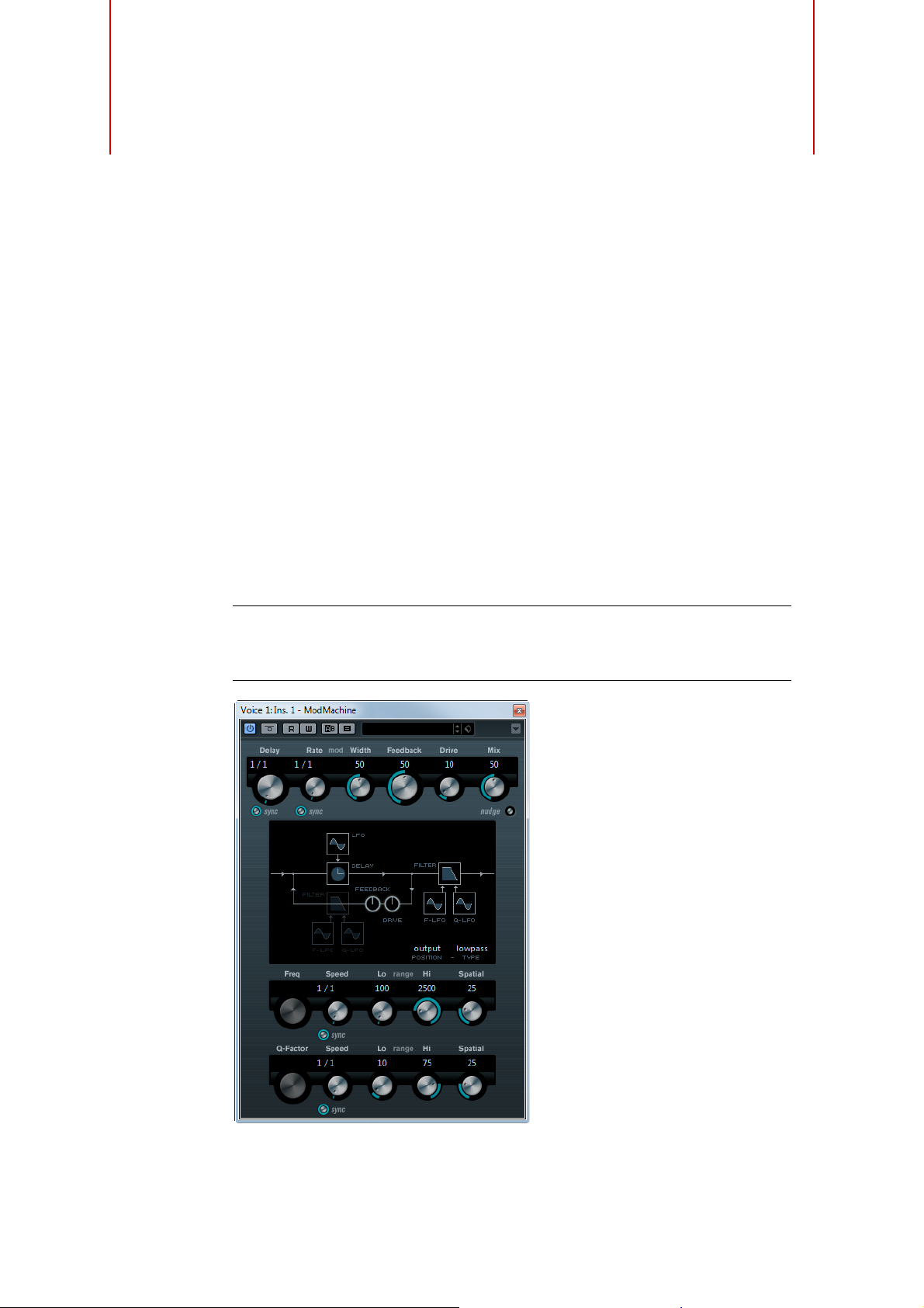
ModMachine combines delay modulation and filter frequency/resonance modulation
and can provide many interesting modulation effects. It also features a Drive
parameter for distortion effects.
The following parameters are available:
Parameter Description
Delay If tempo sync is on, this is where you specify the base note value for
the delay (1/1 to 1/32, straight, triplet, or dotted).
If tempo sync is off, the delay time can be set freely in milliseconds.
Delay –
Sync button
Rate The Rate parameter sets the base note value for tempo syncing the
Rate –
Sync button
Width Sets the amount of delay pitch modulation. Note that although the
Feedback Sets the number of repeats for the delay.
Drive Adds distortion to the feedback loop. The longer the Feedback, the
Mix Sets the level balance between the dry and the wet signal. If
Nudge button Clicking the Nudge button once momentarily speeds up the audio
Signal path graphic
and Filter position
Filter type (in
graphic display)
Freq Sets the cutoff frequency for the filter. It is only available if tempo
Speed Sets the speed of the filter frequency LFO modulation. When using
Speed –
Sync button
Range Lo/Hi These knobs specify the range of the filter frequency modulation.
The button below the Delay knob switches tempo sync for the Delay
parameter on or off.
delay modulation (1/1 to 1/32, straight, triplet, or dotted). If tempo
sync is off, the rate can be set freely.
The button below the Rate knob switches tempo sync for the Rate
parameter on or off.
modulation affects the delay time, the sound is mostly perceived as a
vibrato or chorus-like effect.
more the delay repeats become distorted over time.
ModMachine is used as a send effect, set this to the maximum value
(100
%) as you can control the dry/effect balance with the send.
coming into the plug-in, simulating an analog tape nudge type sound
effect.
The filter can either be placed in the feedback loop of the delay or in
the output path of the effect (after the Drive and Feedback
parameters).
To switch between the “loop” and “output” positions, click on the
Filter section displayed in the graphic or click on the Position field at
the bottom right of the graphic.
Allows you to select a filter type. A low-pass, band-pass, and highpass filter are available.
sync for the Speed parameter is deactivated and the parameter is
set to 0.
tempo sync, the Speed parameter sets the base note value for
tempo syncing the modulation (1/1 to 1/32, straight, triplet, or
dotted). If tempo sync is off, the speed can be set freely.
The button below the Speed knob switches tempo sync for the
Speed parameter on or off.
Both positive (for example, Lo set to 50 and Hi set to 10000) and
negative (for example, Lo set to 5000 and Hi set to 500) ranges can
be set. If tempo sync is off and the Speed is set to zero, these
parameters are inactive and the filter frequency is controlled by the
Freq parameter instead.
6
The Included Effect Plug-ins
Page 7

Delay Plug-ins
Parameter Description
Spatial Introduces an offset between the channels to create a stereo
panorama effect for the filter frequency modulation. Turn clockwise
for a more pronounced stereo effect.
Q-Factor Sets the resonance of the filter. It is only available if filter resonance
LFO tempo sync is deactivated and the Speed parameter is set to 0.
When using tempo sync, the resonance is controlled by the Speed
and Range parameters.
Speed Sets the speed of the filter resonance LFO modulation. When using
tempo sync, the Speed parameter sets the base note value for
tempo syncing the modulation (1/1 to 1/32, straight, triplet, or
dotted). If tempo sync is off, the speed can be set freely.
Speed –
Sync button
Range Lo/Hi These knobs specify the range of the filter resonance modulation.
Spatial Introduces an offset between the channels to create a stereo
The button below the Speed knob switches tempo sync for the
Speed parameter on or off.
Both positive (for example, Lo set to 50 and Hi set to 100) and
negative (for example, Lo set to 100 and Hi set to 50) ranges can
be set. If tempo sync is off and the Speed is set to zero, these
parameters are inactive and the filter resonance is controlled by the
Q-Factor parameter instead.
panorama effect for the filter resonance modulation. Turn
clockwise for a more pronounced stereo effect.
MonoDelay
Cubase LECubase AICubase
Elements
Included with
Side-chain
support
This is a mono delay effect that can either be tempo-based or use freely specified
delay time settings.
The following parameters are available:
Parameter Description
Delay If tempo sync is on, this is where you specify the base note value for
Sync button The button below the Delay knob switches tempo sync on or off.
Feedback Sets the number of repeats for the delay.
X X X X X X –
– – – X X X –
the delay (1/1 to 1/32, straight, triplet, or dotted).
If tempo sync is off, the delay time can be set freely in milliseconds.
Cubase
Artist
Cubase Nuendo NEK
7
The Included Effect Plug-ins
Page 8

Parameter Description
Filter Lo Affects the feedback loop of the effect signal and allows you to roll off
Filter Hi Affects the feedback loop of the effect signal and allows you to roll off
Mix Sets the level balance between the dry and the wet signal. If
Ö If side-chaining is supported, the delay can also be controlled from another signal
source via the side-chain input. When the side-chain signal exceeds the threshold,
the delay repeats are silenced. When the signal drops below the threshold, the delay
repeats reappear. For a description of how to set up side-chain routing, see the
Operation Manual.
PingPongDelay
Delay Plug-ins
low frequencies from 10
activates/deactivates the filter.
high frequencies from 20
knob activates/deactivates the filter.
MonoDelay is used as a send effect, set this to the maximum value as
you can control the dry/effect balance with the send.
Hz up to 800 Hz. The button below the knob
kHz down to 1.2 kHz. The button below the
Cubase LECubase AICubase
Elements
Included with
Side-chain
support
This is a stereo delay effect that alternates each delay repeat between the left and
right channels. The effect can either be tempo-based or use freely specified delay
time settings.
The following parameters are available:
Parameter Description
Delay If tempo sync is on, this is where you specify the base note value for
Sync button The button below the Delay knob switches tempo sync on or off.
Feedback Sets the number of repeats for the delay.
Filter Lo Affects the feedback loop of the effect signal and allows you to roll off
Filter Hi Affects the feedback loop of the effect signal and allows you to roll off
– – X X X X –
– – – X X X –
the delay (1/1 to 1/32, straight, triplet, or dotted).
If tempo sync is off, the delay time can be set freely in milliseconds.
low frequencies up to 800
activates/deactivates the filter.
high frequencies from 20
knob activates/deactivates the filter.
Cubase
Artist
Hz. The button below the knob
kHz down to 1.2 kHz. The button below the
Cubase Nuendo NEK
8
The Included Effect Plug-ins
Page 9

Parameter Description
Spatial Sets the stereo width for the left/right repeats. Turn clockwise for a
Mix Sets the level balance between the dry and the wet signal. If
Ö If side-chaining is supported, the delay can also be controlled from another signal
source via the side-chain input. When the side-chain signal exceeds the threshold,
the delay repeats are silenced. When the signal drops below the threshold, the delay
repeats reappear. For a description of how to set up side-chain routing, see the
Operation Manual.
StereoDelay
Delay Plug-ins
more pronounced stereo ping-pong effect.
PingPongDelay is used as a send effect, set this to the maximum
value as you can control the dry/effect balance with the send.
Cubase LECubase AICubase
Elements
Included with
Side-chain
support
StereoDelay has two independent delay lines which either use tempo-based or freely
specified delay time settings.
The following parameters are available:
Parameter Description
Delay 1 & 2 If tempo sync is on, this is where you specify the base note value for
Sync buttons The buttons below the Delay knobs turn tempo sync on or off for the
Feedback 1 & 2 Set the number of repeats for each delay.
Filter Lo 1 & 2 Affect the feedback loop of the effect signal and allow you to roll off
Filter Hi 1 & 2 Affect the feedback loop of the effect signal and allow you to roll off
Pan 1 & 2 Set the stereo position for each delay.
Mix 1 & 2 Set the level balance between the dry and the wet signal. If
– – – X X X –
– – – X X X –
the delay (1/1 to 1/32, straight, triplet, or dotted).
If tempo sync is off, the delay time can be set freely in milliseconds.
corresponding delay.
low frequencies up to 800
activate/deactivate the filter.
high frequencies from 20
knobs activate/deactivate the filter.
StereoDelay is used as a send effect, set these controls to the
maximum value (100
with the send.
%) as you can control the dry/effect balance
Cubase
Artist
Hz. The buttons below the knobs
kHz down to 1.2 kHz. The buttons below the
Cubase Nuendo NEK
9
The Included Effect Plug-ins
Page 10

Ö If side-chaining is supported, the delay can also be controlled from another signal
source via the side-chain input. When the side-chain signal exceeds the threshold,
the delay repeats are silenced. When the signal drops below the threshold, the delay
repeats reappear. For a description of how to set up side-chain routing, see the
Operation Manual.
Distortion Plug-ins
This section contains descriptions of the plug-ins in the “Distortion” category.
AmpSimulator
Distortion Plug-ins
Cubase LECubase AICubase
Elements
Included with
AmpSimulator is a distortion effect, emulating the sound of various types of guitar amp
and speaker cabinet combinations. A wide selection of amp and cabinet models is
available.
X X X X X X –
Cubase
Artist
Cubase Nuendo NEK
The following parameters are available:
Parameter Description
Amplifier pop-up
menu
Drive Controls the amount of amp overdrive.
Bass Tone control for the low frequencies.
Middle Tone control for the mid frequencies.
Treble Tone control for the high frequencies.
Presence Boosts or dampens the higher frequencies.
Volume Controls the overall output level.
This pop-up menu is opened by clicking on the amplifier name shown
at the top of the amp section. It allows you to select an amplifier
model. The amp section can be bypassed by selecting “No Amp”.
10
The Included Effect Plug-ins
Page 11
BitCrusher
Distortion Plug-ins
Parameter Description
Cabinet pop-up
menu
Damping Lo/Hi Further tone controls for shaping the sound of the selected speaker
This pop-up menu is opened by clicking on the cabinet name shown
at the top of the cabinet section. It allows you to select a speaker
cabinet model. This section can be bypassed by selecting “No
Speaker”.
cabinet. Click on the values, enter a new value and press the [Enter]
key.
Cubase LECubase AICubase
Elements
Included with
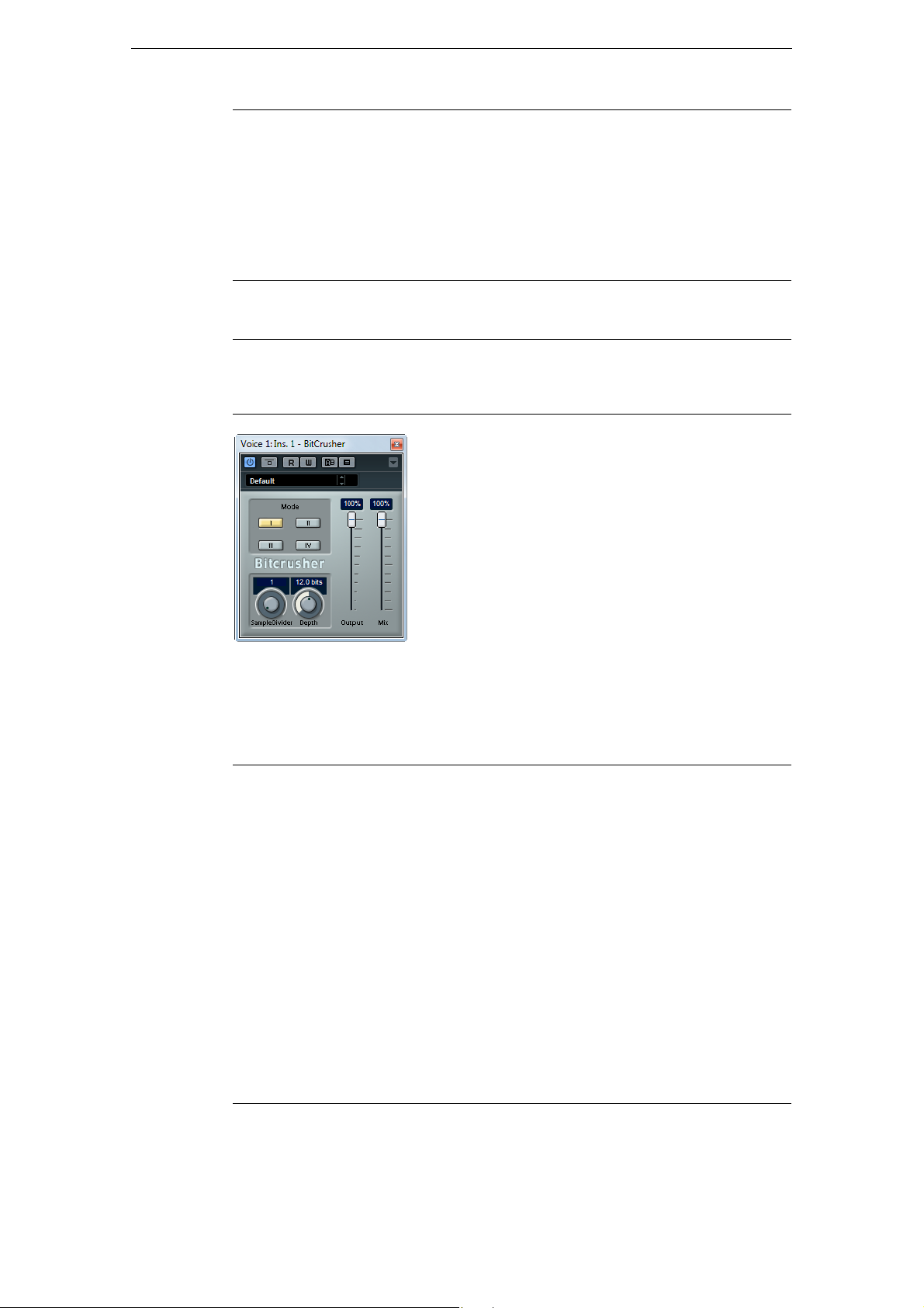
If you are into lo-fi sound, BitCrusher is the effect for you. It offers the possibility of
decimating and truncating the input audio signal by bit reduction, to get a noisy,
distorted sound. For example, you can make a 24-bit audio signal sound like an 8 or
4-bit signal, or even render it completely garbled and unrecognizable.
The following parameters are available:
Parameter Description
Mode Allows you to select one of the four operating modes of BitCrusher.
Sample Divider Sets the amount by which the audio samples are decimated. At the
Depth Defines the bit resolution. A setting of 24 gives the highest audio
Output slider Governs the output level from BitCrusher. Drag the slider upwards to
Mix slider Regulates the balance between the output from BitCrusher and the
X X X X X X –
In each mode the plug-in sounds differently. Modes I and III are
nastier and noisier, while modes II and IV are more subtle.
highest setting (65), nearly all of the information describing the
original audio signal is eliminated, turning the signal into
unrecognizable noise.
quality, while a setting of 1 creates mostly noise.
increase the level.
original audio signal. Drag the slider upwards for a more dominant
effect, and downwards if you want the original signal to be more
prominent.
Cubase
Artist
Cubase Nuendo NEK
11
The Included Effect Plug-ins
Page 12
DaTube
Distortion Plug-ins
Cubase LECubase AICubase
Elements
Included with
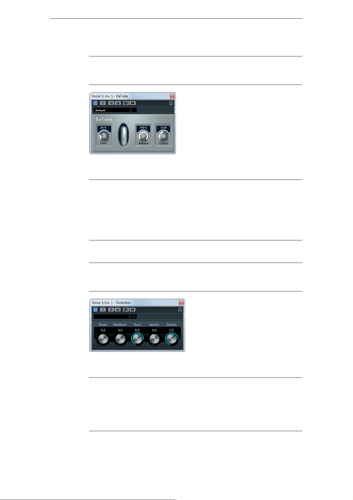
This effect emulates the characteristic warm, lush sound of a tube amplifier.
The following parameters are available:
Parameter Description
Drive Regulates the pre-gain of the amplifier. Use high values if you want an
Balance Controls the balance between the signal processed by the Drive
Output Adjusts the post-gain, or output level, of the amplifier.
– X X X X X –
overdriven sound just on the verge of distortion.
parameter and the dry input signal. For maximum drive effect, set this
to its highest value.
Cubase
Artist
Cubase Nuendo NEK
Distortion
Cubase LECubase AICubase
Elements
Included with
Distortion adds crunch to your tracks.
The following parameters are available:
Parameter Description
Boost Increases the distortion amount.
Feedback Feeds part of the output signal back to the effect input, increasing the
Tone Lets you select a frequency range to which to apply the distortion
X X X X X X –
distortion effect.
effect.
Cubase
Artist
Cubase Nuendo NEK
12
The Included Effect Plug-ins
Page 13

Parameter Description
Spatial Changes the distortion characteristics of the left and right channel,
Output Raises or lowers the signal going out of the effect.
Grungelizer
Distortion Plug-ins
thus creating a stereo effect.
Cubase LECubase AICubase
Elements
Included with
Grungelizer adds noise and static to your recordings – kind of like listening to a radio
with bad reception, or a worn and scratched vinyl record. The following parameters
are available:
Parameter Description
Crackle Adds crackle to create that old vinyl record sound. The farther to the
RPM switch When emulating the sound of a vinyl record, this switch lets you set
Noise Regulates the amount of static noise added.
Distort Adds distortion.
EQ Turn this knob to the right to cut off the low frequencies, and create a
AC Emulates a constant, low hum of AC current.
Frequency switch Sets the frequency of the AC current (50 or 60 Hz), and thus the
Timeline Regulates the amount of overall effect. The farther to the right (1900)
X X X X X X –
right you turn the knob, the more crackle is added.
the speed of the record in RPM (revolutions per minute).
more hollow, lo-fi sound.
pitch of the AC hum.
you turn the knob, the more noticeable the effect.
Cubase
Artist
Cubase Nuendo NEK
13
The Included Effect Plug-ins
Page 14

SoftClipper
Distortion Plug-ins
Cubase LECubase AICubase
Elements
Included with
This effect adds soft overdrive, with independent control over the second and third
harmonic.
The following parameters are available:
Parameter Description
Input Regulates the pre-gain. Use high values if you want an overdriven
Mix Setting Mix to 0 means that no processed signal is added to the
Output Adjusts the post-gain, or output level.
Second Adjusts the amount of the second harmonic in the processed signal.
Third Adjusts the amount of the third harmonic in the processed signal.
– – – – X X –
sound just on the verge of distortion.
original signal.
Cubase
Artist
Cubase Nuendo NEK
14
The Included Effect Plug-ins
Page 15

VST Amp Rack
Distortion Plug-ins
Cubase LECubase AICubase
Elements
Included with
The VST Amp Rack is a powerful guitar amp simulator. It offers a choice of amplifiers
and speaker cabinets that can be combined with stomp box effects.
– – X X X X –
Cubase
Artist
Cubase Nuendo NEK
At the top of the plug-in panel there are six buttons, arranged according to the
position of the corresponding elements in the signal chain. These buttons open
different pages in the Display section of the plug-in panel: Pre-Effects, Amplifiers,
Cabinets, Post-Effects, Microphone Position, and Master.
Below the Display section, the selected amplifier is shown. The color and texture of
the area below the amplifier indicate the selected cabinet.
Pre/Post-Effects
On the Pre-Effects and the Post-Effects pages, you can select up to six common
guitar effects. On both pages the same effects are available, the only difference being
the position in the signal chain (before and after the amplifier). On each page, every
effect can be used once.
Each effect features an On/Off button known from stompbox effects, as well as
individual parameters. The following effects and parameters are available:
Effect Option Description
Wah Wah Pedal Controls the filter frequency sweep.
Volume Pedal Controls the level of the signal passing through the
Compressor Intensity Changes the intensity of the compressor effect.
effect.
15
The Included Effect Plug-ins
Page 16

Distortion Plug-ins
Effect Option Description
Limiter Threshold Determines the maximum output level. Signal levels
above the set threshold are cut off.
Release Sets the time after which the gain returns to the original
level.
Maximizer Amount Determines the loudness of the signal.
Chorus Rate Allows you to set the sweep rate.
This parameter can be synchronized to the project
tempo, see
Width Determines the depth of the chorus effect. Higher
settings produce a more pronounced effect.
Phaser Rate Allows you to set the sweep rate.
This parameter can be synchronized to the project
tempo, see
Width Determines the width of the modulation effect between
higher and lower frequencies.
Flanger Rate Allows you to set the sweep rate.
This parameter can be synchronized to the project
tempo, see
Feedback Determines the character of the flanger effect. Higher
settings produce a more metallic sounding sweep.
Mix Sets the level balance between the dry and the wet
signal.
Tremolo Rate Allows you to set the modulation speed.
This parameter can be synchronized to the project
tempo, see
Depth Governs the depth of the amplitude modulation.
Octaver Direct Adjusts the mix of the original signal and the generated
voices. A value of 0 means only the generated and
transposed signal is heard. By raising this value, more of
the original signal is heard.
Octave 1 Adjusts the level of the signal that is generated one
octave below the original pitch. A setting of 0 means
that the voice is muted.
Octave 2 Adjusts the level of the signal that is generated two
octaves below the original pitch. A setting of 0 means
that the voice is muted.
Delay Delay Sets the delay time in milliseconds.
This parameter can be synchronized to the project
tempo, see
Feedback Sets the number of repeats for the delay.
Mix Sets the level balance between the dry and the wet
signal.
“Sync Mode” on page 18.
“Sync Mode” on page 18.
“Sync Mode” on page 18.
“Sync Mode” on page 18.
“Sync Mode” on page 18.
16
The Included Effect Plug-ins
Page 17

Distortion Plug-ins
Effect Option Description
Tape Delay Delay Tape Delay creates a delay effect known from tape
machines. The Delay parameter sets the delay time in
milliseconds.
This parameter can be synchronized to the project
tempo, see
Feedback Sets the number of repeats for the delay.
Mix Sets the level balance between the dry and the wet
signal.
Tape Ducking
Delay
Overdrive Drive Overdrive creates a tube-like overdrive effect. The
Fuzz Boost Fuzz creates a rather harsh distortion effect. The higher
Gate Threshold Determines the level where Gate is activated. Signal
Equalizer Low Changes the level of the low-frequency portion of the
Reverb Type A convolution-based reverb effect. The Type parameter
Delay Tape Ducking Delay creates a delay effect known from
tape machines with a ducking parameter. The Delay
parameter sets the delay time in milliseconds.
This parameter can be synchronized to the project
tempo, see
Feedback Sets the number of repeats for the delay.
Duck Works like an automatic mix parameter. If the level of the
input signal is high, the portion of the effect signal is
lowered, or ducked (low internal mix value).
If the level of the input signal is low, the portion of the
effect signal is raised (high internal mix value). This way
the delayed guitar signal stays rather dry during loud or
intensely played passages.
higher the Drive value, the more harmonics are being
added to the output signal of this effect.
Tone Works as a filter effect on the added harmonics.
Level Adjusts the output level.
the Boost value, the more distortion is being created.
Tone Works as a filter effect on the added harmonics.
Level Adjusts the output level.
levels above the set threshold trigger the gate to open,
and signal levels below the set threshold close the gate.
Release Sets the time after which the gate closes.
incoming signal.
Middle Changes the level of the mid-frequency portion of the
incoming signal.
High Changes the level of the high-frequency portion of the
incoming signal.
allows you to switch between different reverb types
(Studio, Hall, Plate, and Room).
Mix Sets the level balance between the dry and the wet
signal.
“Sync Mode” on page 18.
“Sync Mode” on page 18.
17
The Included Effect Plug-ins
Page 18

Distortion Plug-ins
!
Sync Mode
For some controls, the sync mode can be activated to synchronize the corresponding
parameter with the tempo of the host application. These plug-in parameters are then
used to specify the base note value for tempo syncing (1/1 to 1/32, straight, triplet, or
dotted).
The names of these parameters are underlined. Click a knob to activate or deactivate
tempo sync. An LED at the top right of the knob indicates that Sync mode is active.
You can then select a base note value for tempo syncing from the pop-up menu above
the control.
Using Effects
• To insert a new effect, click the plus button that appears when you point the
mouse at an empty plug-in slot or at one of the arrows before or after a used effect
slot.
• To remove an effect from an effect slot, click the effect name and select “None”
from the pop-up menu.
• To change the order of the effects in the chain, click on an effect and drag it to
another position.
• To activate or deactivate an effect, click the pedal-like button below the effect
name.
When an effect is active, the LED next to the button is lit.
Amplifiers
Pre-effects and post-effects can be mono or stereo, depending on the track
configuration.
Ö Using quick controls you can conveniently set up an external MIDI device such as a
foot controller to control the VST Amp Rack effects. For more information about quick
controls, see the Operation Manual.
The amps available on the Amplifiers page were modeled on real-life amplifiers. Each
amp features settings typical for guitar recording, such as gain, equalizers, and master
volume. The sound-related parameters Bass, Middle, Treble, and Presence have a
significant impact on the overall character and sound of the corresponding amp.
The following amp models are available:
- Plexi – Classic British rock tone; extremely transparent sound, very responsive.
- Plexi Lead – British rock tone of the 70’s and 80’s.
- Diamond – The cutting edge hard rock and metal sounds of the 90’s.
- Blackface – Classic American clean tone.
- Tweed – Clean and crunchy tones; originally developed as a bass amp.
- Deluxe – American crunch sound coming from a rather small amp with a big tone.
- British Custom – Produces the sparkling clean or harmonically distorted rhythm
sounds of the 60’s.
The different amps keep their settings when you switch models. However, if you want
to use the same settings after reloading the plug-in, you need to set up a preset.
Using Amplifiers
• To switch amps on the Amplifiers page, click the model that you want to use.
Select “No Amplifier” if you only want to use the cabinets and effects.
18
The Included Effect Plug-ins
Page 19

Cabinets
The cabinets available on the Cabinets page simulate real-life combo boxes or
speakers. For each amp, a corresponding cabinet type is available. However, you can
combine amps and cabinets at will.
Using Cabinets
• To switch cabinets on the Cabinets page, click the model that you want to use.
Select “No Cabinet” if you only want to use the amps and effects.
• If you select “Link Amplifier & Cabinet Choice”, the plug-in automatically selects
the cabinet corresponding to the selected amp model.
Microphone Position
On the Microphone Position page, you can choose between 7 positions to place the
microphone. These positions result from two different angles (center and edge) and
three different distances from the speaker, as well as an additional center position at
an even greater distance from the speaker.
You can choose between two microphone types: a large-diaphragm condenser
microphone and a dynamic microphone. Crossfading between the characteristics of
the two microphones is also possible.
Distortion Plug-ins
Master
Placing the Microphone
• To select a microphone position, click the corresponding ball in the graphic.
The selected position is marked in red.
• To select one of the microphone types or blend between the two types, turn the
Mix control between the two microphones.
Use the Master page to fine-tune the sound.
Input/Output Level Meters
The input and output level meters on the left and the right of the Master section show
the signal level of your audio. The rectangle on the input meter indicates the optimum
incoming level range. In compact view, the input and output levels are indicated by
two LEDs at the top left and right.
Using the Master Controls
• To activate/deactivate the Equalizer, click the pedal-like On/Off button.
When the Equalizer is active, the LED next to the button is lit.
• To activate/deactivate an equalizer band, click the corresponding Gain knob.
When a band is active, the LED to the left of the Gain knob is lit.
• To tune your guitar strings, click the pedal-like On/Off button to activate the Tuner
and play a string.
When the correct pitch is displayed and the row of LEDs below the digital display
is green, the string is tuned correctly. The more red LEDs on the left/right are lit,
the lower/higher the pitch.
• To mute the output signal of the plug-in, click the pedal-like Master button.
When the LED is off, the output is muted. Use this to tune your guitar in silence, for
example.
• To change the volume of the output signal, use the Level control in the Master
section.
19
The Included Effect Plug-ins
Page 20

• To process the pre-effects, the amplifier, and the cabinets in full stereo mode, make
sure that the plug-in is inserted on a stereo track, and activate the Stereo button.
View Settings
Two different views for the VST Amp Rack plug-in panel are available: the default view
and a compact view, which takes up less screen space.
In the default view, you can use the top buttons to open the corresponding page in the
Display section above the amp controls. You can horizontally resize the plug-in panel
by clicking and dragging the edges or corners.
In the compact view the page display is hidden from view. You can still change the
amp settings and switch amps or cabinets using the mouse wheel.
Using the Smart Controls
Smart controls become visible on the plug-in frame when the mouse pointer is
positioned on the plug-in panel.
Switching between Default and Compact View
• To toggle between the different views, click the down/up arrow button
(Show/Hide Extended Display) at the top center of the plug-in frame.
Distortion Plug-ins
Changing the Amplifier and Cabinet Selection in the Compact View
In the compact view, a smart control on the lower border of the plug-in frame allows
you to select different amplifier and cabinet models.
• To select a different amplifier or cabinet, click the name and select a different
model from the pop-up menu.
• To lock the amplifier and cabinet combination, activate the “Link/Unlink Amplifier &
Cabinet Choice” button.
If you now select another amp model, the cabinet selection follows. However, if
you select a different cabinet model, the lock is deactivated.
Previewing Effect Settings
In both views, you can show a preview of the pre- and post-effects that you selected
on the corresponding pages:
• Click and hold the “Show Pre-Effects” or “Show Post-Effects” button at the
bottom left or right of the plug-in frame.
20
The Included Effect Plug-ins
Page 21
Dynamics Plug-ins
This section contains descriptions of the plug-ins in the “Dynamics” category.
Brickwall Limiter
Dynamics Plug-ins
Cubase LECubase AICubase
Elements
Included with
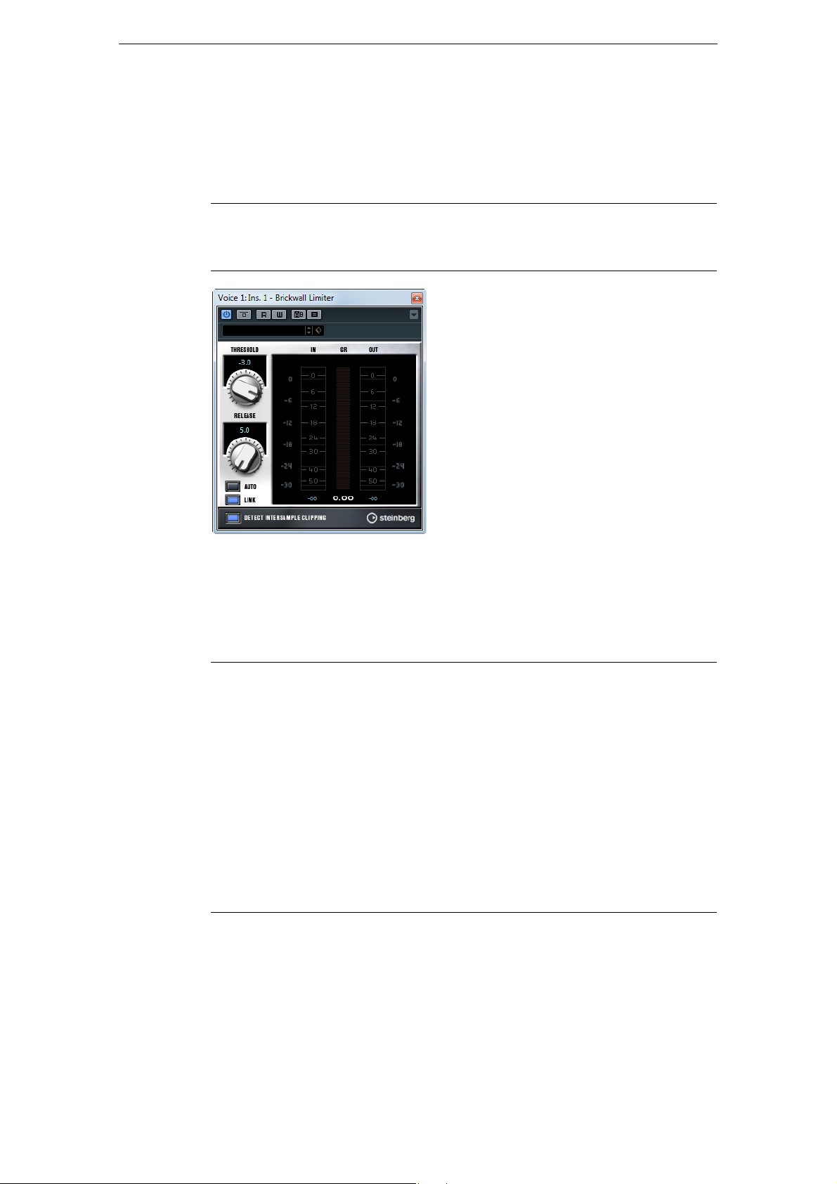
Brickwall Limiter ensures that the output level never exceeds a set limit. Due to its fast
attack time, Brickwall Limiter can reduce even short audio level peaks without creating
audible artifacts. However, this plug-in creates a latency of 1ms. Brickwall Limiter
features separate meters for input, output, and the amount of limiting. Position this
plug-in at the end of the signal chain, before dithering.
The following parameters are available:
– – – X X X –
Cubase
Artist
Cubase Nuendo NEK
Parameter Description
Threshold
(-20 to 0 dB)
Release
(10 to 1000 ms or
Auto mode)
Link button If this button is activated, Brickwall Limiter uses the channel with the
Detect
Intersample
Clipping
Ö Brickwall Limiter is designed for the reduction of occasional peaks in the signal. If the
Gain Reduction meter indicates constant limiting, try raising the threshold or lowering
the overall level of the input signal.
Only signal levels above the set threshold are processed.
Sets the time after which the gain returns to the original level when the
signal drops below the threshold. If the Auto button is activated,
Brickwall Limiter automatically finds the optimal release setting,
depending on the audio material.
highest level to analyze the input signal. If the Link button is
deactivated, each channel is analyzed separately.
In this mode, Brickwall Limiter detects and limits signal levels between
two samples to prevent distortion when converting digital signals to
analog.
21
The Included Effect Plug-ins
Page 22
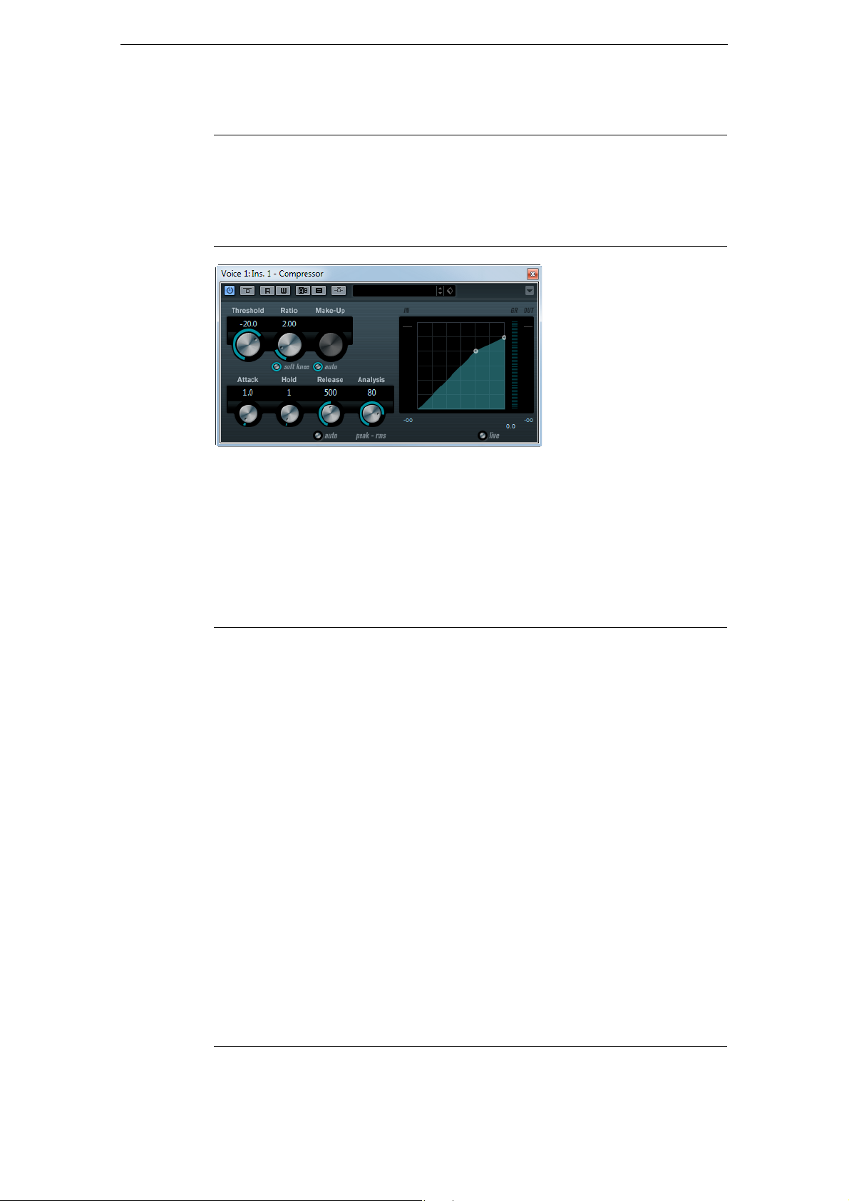
Compressor
Dynamics Plug-ins
Cubase LECubase AICubase
Elements
Included with
Side-chain
support
Compressor reduces the dynamic range of the audio, making softer sounds louder or
louder sounds softer, or both. Compressor features separate controls for threshold,
ratio, attack, hold, release, and make-up gain parameters. Compressor features a
separate display that graphically illustrates the compressor curve shaped according
to the Threshold and Ratio parameter settings. Compressor also features a Gain
Reduction meter that shows the amount of gain reduction in dB, Soft knee/Hard knee
compression modes and a program-dependent Auto feature for the Release
parameter.
The following parameters are available:
– – X X X X –
– – – X X X –
Cubase
Artist
Cubase Nuendo NEK
Parameter Description
Threshold
(-60 to 0 dB)
Ratio
(1:1 to 8:1)
Soft Knee button If this button is off, signals above the threshold are compressed
Make-up
(0 to 24 dB or
Auto mode)
Attack
(0.1 to 100 ms)
Hold
(0 to 5000 ms)
Determines the level where Compressor kicks in. Signal levels above
the set threshold are affected, but signal levels below are not
processed.
Determines the amount of gain reduction applied to signals above the
set threshold. A ratio of 3:1 means that for every 3
increases, the output level increases by only 1
instantly according to the set ratio (hard knee). When Soft Knee is
activated, the onset of compression is more gradual, producing a less
drastic result.
Compensates for output gain loss, caused by compression. If the Auto
button is activated, the knob becomes dark and the output is
automatically adjusted for gain loss.
Determines how fast Compressor responds to signals above the set
threshold. If the attack time is long, more of the early part of the signal
(attack) passes through unprocessed.
Sets the time the applied compression affects the signal after
exceeding the threshold.
Short hold times are useful for DJ-style ducking, while longer hold
times are required for music ducking, for example, when working on a
documentary film.
dB the input level
dB.
22
The Included Effect Plug-ins
Page 23
Dynamics Plug-ins
Parameter Description
Release
(10 to 1000 ms or
Auto mode)
Analysis
(0 to 100)
(Pure Peak to
Pure RMS)
Live button When this button is activated, the look-ahead feature of Compressor is
Ö If side-chaining is supported, the compression can also be controlled from another
signal source via the side-chain input. When the side-chain signal exceeds the
threshold, the compression is triggered. For a description of how to set up side-chain
routing, see the Operation Manual.
Sets the time after which the gain returns to the original level when the
signal drops below the threshold. If the Auto button is activated,
Compressor automatically finds an optimal release setting that varies
depending on the audio material.
Determines whether the input signal is analyzed according to peak or
RMS values (or a mixture of both). A value of 0 is pure peak and
100
pure RMS. RMS mode operates using the average power of the
audio signal as a basis, whereas Peak mode operates more on peak
levels. As a general guideline, RMS mode works better on material with
few transients such as vocals, and Peak mode better for percussive
material, with a lot of transient peaks.
disengaged. Look ahead produces more accurate processing, but
adds a certain amount of latency as a trade-off. When Live mode is
activated, there is no latency, which might be better for live processing.
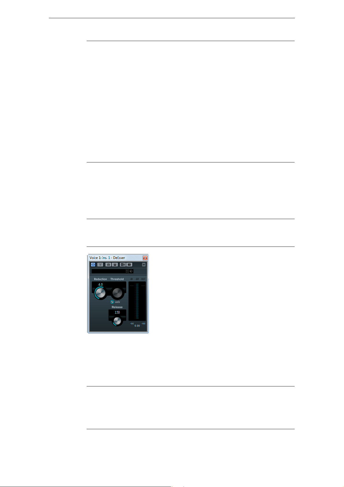
DeEsser
Cubase LECubase AICubase
Elements
Included with
A de-esser reduces excessive sibilance, primarily for vocal recordings. Basically, it is a
special type of compressor that is tuned to be sensitive to the frequencies produced
by the “s” sound, hence the name de-esser. Close proximity microphone placement
and equalizing can lead to situations where the overall sound is just right, but there is
a problem with sibilants.
The following parameters are available:
– – – – X X –
Cubase
Artist
Cubase Nuendo NEK
Parameter Description
Reduction Controls the intensity of the de-essing effect.
Threshold When the Auto option is deactivated, you can use this control to set
a threshold for the incoming signal level, above which the plug-in
starts to reduce the sibilants.
23
The Included Effect Plug-ins
Page 24
Dynamics Plug-ins
Parameter Description
Auto Automatically and continually chooses an optimum threshold setting
independent of the input signal. The Auto option does not work for
low-level signals (< -30
such a file, set the threshold manually.
Release Sets the time after which the de-essing effect returns to zero when
the signal drops below the threshold.
Level meters Indicate the dB values of the input (IN) and output (OUT) signals as
well as the value by which the level of the sibilant (or s-frequency) is
reduced (GR). The gain reduction meter shows values between 0
(no reduction) and -20
20
dB).
Positioning the DeEsser in the Signal Chain
When recording a voice, the de-esser’s position in the signal chain is usually located
after the microphone pre-amp and before a compressor/limiter. This keeps the
compressor/limiter from unnecessarily limiting the overall signal dynamics.
dB peak level). To reduce the sibilants in
dB
dB (the s-frequency level is lowered by
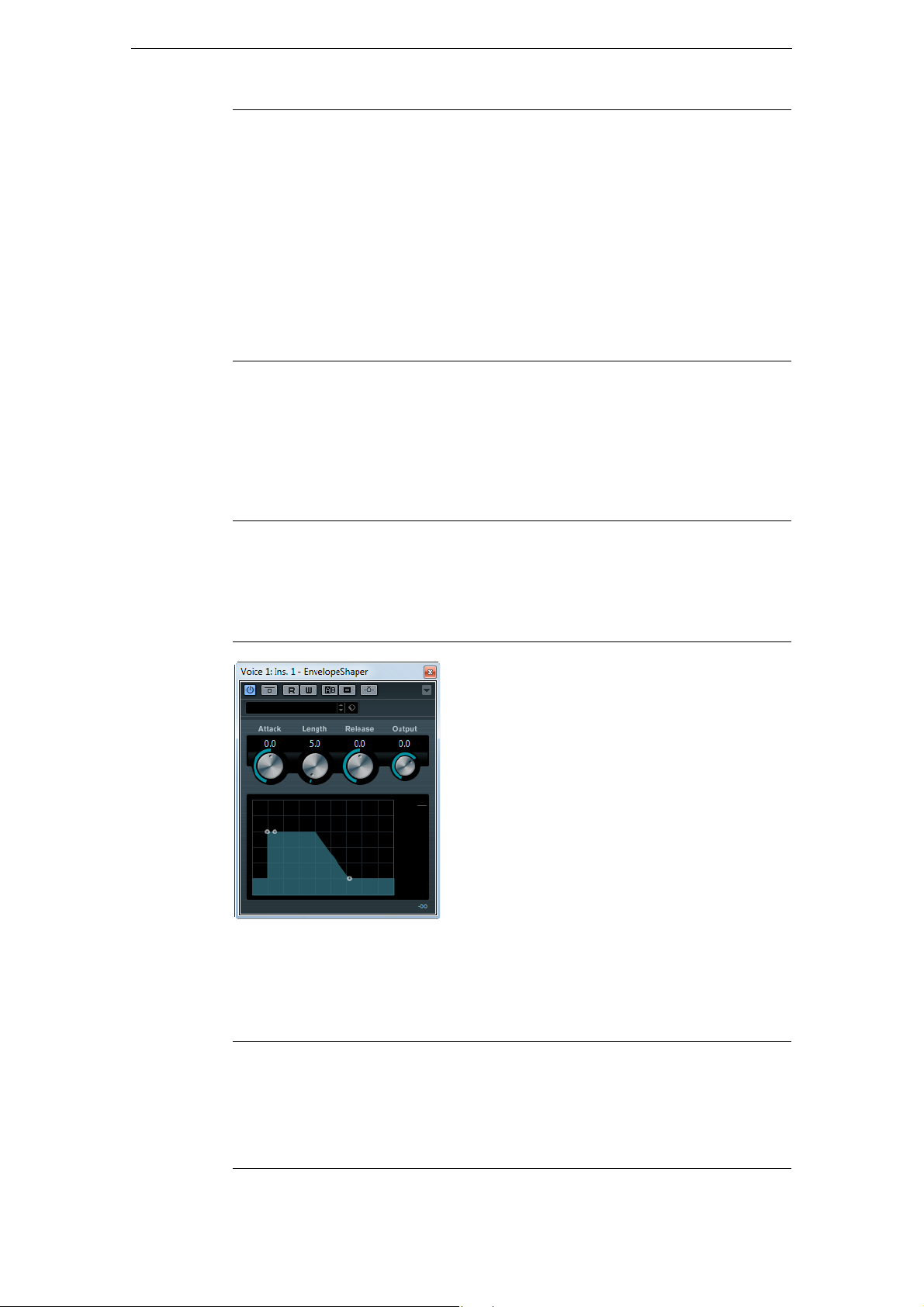
EnvelopeShaper
Included with
Side-chain
support
EnvelopeShaper can be used to attenuate or boost the gain of the attack and release
phase of audio material. You can either use the knobs or drag the breakpoints in the
graphical display to change parameter values. Be careful with levels when boosting
the gain and if needed reduce the output level to avoid clipping.
Cubase LECubase AICubase
Elements
– – – X X X –
– – – X X X –
Cubase
Artist
Cubase Nuendo NEK
The following parameters are available:
Parameter Description
Attack (-20 to 20 dB) Changes the gain of the attack phase of the signal.
Length (5 to 200 ms) Determines the length of the attack phase.
Release (-20 to 20 dB) Changes the gain of the release phase of the signal.
Output (-24 to 12 dB) Sets the output level.
24
The Included Effect Plug-ins
Page 25
Ö If side-chaining is supported, the effect can also be controlled from another signal
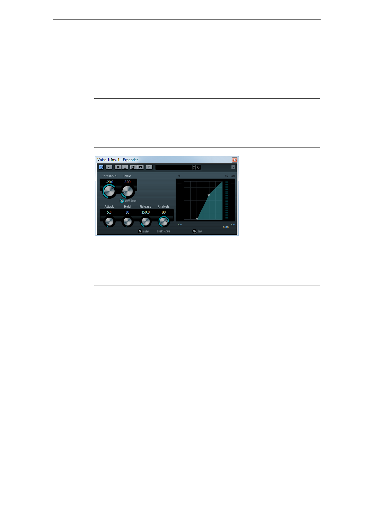
Expander
Dynamics Plug-ins
source via the side-chain input. When the side-chain signal exceeds the threshold,
the effect is triggered. For a description of how to set up side-chain routing, see the
Operation Manual.
Cubase LECubase AICubase
Elements
Included with
Side-chain
support
Expander reduces the output level in relation to the input level for signals below the
set threshold. This is useful when you want to enhance the dynamic range or reduce
the noise in quiet passages. You can either use the knobs or drag the breakpoints in
the graphical display to change the Threshold and the Ratio parameter values.
The following parameters are available:
– – – – X X –
– – – – X X –
Cubase
Artist
Cubase Nuendo NEK
Parameter Description
Threshold
(-60 to 0 dB)
Ratio
(1:1 to 8:1)
Soft Knee button If this button is off, signals below the threshold are expanded instantly
Attack (0.1 to
100
Hold (0 to
2000
Release
(10 to 1000 ms or
Auto mode)
ms)
ms)
Determines the level where expansion kicks in. Signal levels below the
set threshold are affected, but signal levels above are not processed.
Determines the amount of gain boost applied to signals below the set
threshold.
according to the set ratio (hard knee). When “Soft Knee” is activated,
the onset of expansion is more gradual, producing a less drastic result.
Determines how fast Expander responds to signals below the set
threshold. If the attack time is long, more of the early part of the signal
(attack) passes through unprocessed.
Sets the time the applied expansion affects the signal below the
threshold.
Sets the time after which the gain returns to the original level when the
signal exceeds the threshold. If the Auto button is activated, Expander
automatically finds an optimal release setting that varies depending on
the audio material.
25
The Included Effect Plug-ins
Page 26

Gate
Dynamics Plug-ins
Parameter Description
Analysis
(0 to 100)
(Pure Peak to
Pure RMS)
Live button When this button is activated, the look-ahead feature of Expander is
Ö If side-chaining is supported, the expansion can also be controlled from another signal
source via the side-chain input. When the side-chain signal exceeds the threshold, the
expansion is triggered. For a description of how to set up side-chain routing, see the
Operation Manual.
Determines whether the input signal is analyzed according to peak or
RMS values (or a mixture of both). A value of 0 is pure peak and
100
pure RMS. RMS mode operates using the average power of the
audio signal as a basis, whereas Peak mode operates more on peak
levels. As a general guideline, RMS mode works better on material
with few transients such as vocals, and Peak mode better for
percussive material, with a lot of transient peaks.
disengaged. Look ahead produces more accurate processing, but
adds a certain amount of latency as a trade-off. When Live mode is
activated, there is no latency, which might be better for live processing.
Cubase LECubase AICubase
Elements
Included with
Side-chain
support
Gating, or noise gating, silences audio signals below a set threshold level. As soon as
the signal level exceeds the set threshold, the gate opens to let the signal through.
The following parameters are available:
Parameter Description
Threshold
(-60 to 0 dB)
State LED Indicates whether the gate is open (LED lights up in green), closed
Filter section
(LP,
BP, and HP)
– – – X X X –
– – – X X X –
Determines the level where Gate is activated. Signal levels above the
set threshold trigger the gate to open, and signal levels below the set
threshold close the gate.
(LED lights up in red), or something in between (LED lights up in
yellow).
When the Side-Chain button is activated, you can use these buttons
to set the filter type to low-pass, band-pass, or high-pass.
Cubase
Artist
Cubase Nuendo NEK
26
The Included Effect Plug-ins
Page 27

Dynamics Plug-ins
Parameter Description
Side-Chain button Activates the side-chain filter. The input signal can then be shaped
according to set filter parameters. Internal side-chaining can be
useful for tailoring how the gate operates.
Center (50 to
20000
Hz)
Q-Factor (0.01 to
10000)
Monitor button Allows you to monitor the filtered signal.
Attack (0.1 to
1000
ms)
Hold
(0 to 2000 ms)
Release
(10 to 1000 ms or
Auto mode)
Analysis
(0 to 100)
(Pure Peak to Pure
RMS)
Live button When this button is activated, the look-ahead feature of Gate is
When the Side-Chain button is activated, this sets the center
frequency of the filter.
When the Side-Chain button is activated, this sets the resonance of
the filter.
Sets the time after which the gate opens after being triggered.
Deactivate the Live button to make sure that the gate is already open
when a signal above the threshold level is played back. Gate
manages this by looking ahead in the audio material, checking for
signals loud enough to pass the gate.
Determines how long the gate stays open after the signal drops
below the threshold level.
Sets the time after which the gate closes (after the set hold time). If
the Auto button is activated, Gate finds an optimal release setting,
depending on the audio material.
Determines whether the input signal is analyzed according to peak or
RMS values (or a mixture of both). A value of 0 is pure Peak and
100
pure RMS. RMS mode operates using the average power of the
audio signal as a basis, whereas Peak mode operates more on peak
levels. As a general guideline, RMS mode works better on material
with few transients such as vocals, and Peak mode better for
percussive material, with a lot of transient peaks.
disengaged. Look ahead produces more accurate processing, but
adds a certain amount of latency as a trade-off. When Live mode is
activated, there is no latency, which might be better for live
processing.
Ö If side-chaining is supported, the gate can also be controlled from another signal source
via the side-chain input. When the side-chain signal exceeds the threshold, the gate
opens. For a description of how to set up side-chain routing, see the Operation
Manual.
27
The Included Effect Plug-ins
Page 28

Limiter
Dynamics Plug-ins
Cubase LECubase AICubase
Elements
Included with
Limiter is designed to ensure that the output level never exceeds a set output level, to
avoid clipping in following devices. Limiter can adjust and optimize the Release
parameter automatically according to the audio material, or it can be set manually.
Limiter also features separate meters for the input, output and the amount of limiting
(middle meters).
The following parameters are available:
– X X X X X –
Cubase
Artist
Cubase Nuendo NEK
Parameter Description
Input
(-24 to +24 dB)
Output
(-24 to +6 dB)
Release
(0.1 to 1000 ms or
Auto mode)
Adjusts the input gain.
Determines the maximum output level.
Sets the time after which the gain returns to the original level. If the
Auto button is activated, Limiter automatically finds an optimal
release setting that varies depending on the audio material.
28
The Included Effect Plug-ins
Page 29
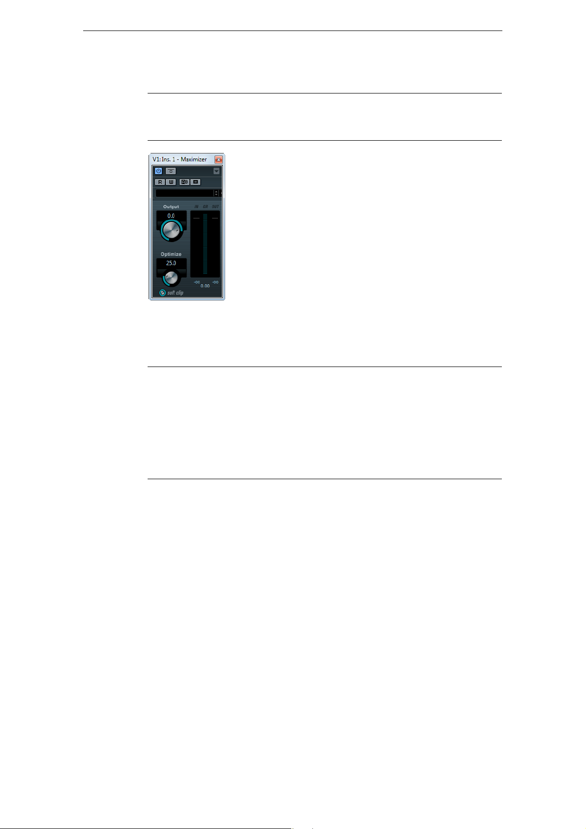
Maximizer
Dynamics Plug-ins
Cubase LECubase AICubase
Elements
Included with
Maximizer raises the loudness of audio material without the risk of clipping. Optionally,
there is a soft clip function that removes short peaks in the input signal and introduces
a warm tube-like distortion to the signal.
The following parameters are available:
Parameter Description
Output
(-24 to +6 dB)
Optimize
(0 to 100)
Soft Clip button When this button is activated, Maximizer starts limiting (or clipping) the
– – – X X X –
Determines the maximum output level. Should normally be set to 0 to
avoid clipping.
Determines the loudness of the signal.
signal softly, at the same time generating harmonics which add a
warm, tube-like characteristic to the audio material.
Cubase
Artist
Cubase Nuendo NEK
29
The Included Effect Plug-ins
Page 30

MIDI Gate
Dynamics Plug-ins
Cubase LECubase AICubase
Elements
Included with
Gating, in its fundamental form, silences audio signals below a set threshold level.
When a signal rises above the set level, the gate opens to let the signal through while
signals below the set level are cut off. MIDI Gate, however, is not triggered by
threshold levels, but MIDI notes. Hence it needs both audio and MIDI data to function.
Setting up
To set up MIDI Gate, proceed as follows:
1. Select the audio to be affected by MIDI Gate.
This can be audio material from any audio track, or even a live audio input
(provided you have a low latency audio card).
2. Select MIDI Gate as an insert effect for the audio track.
The MIDI Gate control panel opens.
3. Select a MIDI track to control the MIDI Gate effect.
This can be an empty MIDI track or a MIDI track containing data, it does not matter.
However, if you wish to use MIDI Gate in realtime – as opposed to using a
recorded part – the track has to be selected for the effect to receive the MIDI
output.
– – – X X X –
Cubase
Artist
Cubase Nuendo NEK
4. Open the “Output Routing” pop-up menu for the MIDI track and select the “MIDI
Gate” option.
The MIDI output from the track is now routed to the MIDI Gate effect.
What to do next depends on whether you are using live or recorded audio and
whether you are using realtime or recorded MIDI. We assume for the purposes of this
manual that you are using recorded audio, and play the MIDI in realtime.
5. Make sure the MIDI track is selected, and start playback.
6. Play a few notes on your MIDI keyboard.
As you can hear, the audio track material is affected by what you play on your MIDI
keyboard.
30
The Included Effect Plug-ins
Page 31

Dynamics Plug-ins
The following MIDI Gate parameters are available:
Parameter Description
Attack Determines how long it takes for the gate to open after receiving a
signal that triggers it.
Hold Regulates how long the gate remains open after a note-on or note-off
message (see Hold Mode).
Release Determines how long it takes for the gate to close (in addition to the
value set with the Hold parameter).
Note To Attack Determines to which extent the velocity values of the MIDI notes
affect the attack. The higher the value, the more the attack time
increases with high note velocities. Negative values give shorter
attack times with high velocities. If you do not wish to use this
parameter, set it to the 0
Note To Release Determines to which extent the velocity values of the MIDI notes
affect the release. The higher the value, the more the release time
increases. If you do not wish to use this parameter, set it to the
0
position.
Velocity To VCA Controls to which extent the velocity values of the MIDI notes
determine the output volume. At a value of 127 the volume is
controlled entirely by the velocity values, and at a value of 0 the
velocities have no effect on the volume.
Hold Mode Use this switch to set the Hold Mode. In Note-On mode, the gate
only remains open for the time set with the Hold and Release
parameters, regardless of the length of the MIDI note that triggered
the gate. In Note-Off mode, the gate remains open for as long as the
MIDI note plays, and then the Hold and Release parameters are
applied.
position.
31
The Included Effect Plug-ins
Page 32

MultibandCompressor
Dynamics Plug-ins
Included with
Cubase LECubase AICubase
Elements
– – – – X X –
Cubase
Artist
Cubase Nuendo NEK
The MultibandCompressor allows a signal to be split into a maximum of four frequency
bands, each with its own freely adjustable compressor characteristic. The signal is
processed on the basis of the settings that you have made in the Frequency Band and
Compressor sections. You can specify the level, bandwidth and compressor
characteristics for each band by using the various controls.
The Frequency Band Editor
The Frequency Band editor in the upper half of the panel is where you set the width of
the frequency bands as well as their level after compression. Two value scales and a
number of handles are available. The vertical value scale to the left shows the input
gain level of each frequency band. The horizontal scale shows the available frequency
range.
The handles provided in the Frequency Band editor can be dragged with the mouse.
You use them to set the corner frequency range and the input gain levels for each
frequency bands.
- The handles at the sides are used to define the frequency range of the different
frequency bands.
- By using the handles on top of each frequency band, you can attenuate or boost
the input gain by ±15
Bypassing Frequency Bands
Each frequency band can be bypassed using the B button in each compressor
section.
dB after compression.
Soloing Frequency Bands
A frequency band can be soloed using the S button in each compressor section. Only
one band can be soloed at a time.
32
The Included Effect Plug-ins
Page 33

Dynamics Plug-ins
Using the Compressor Section
By moving breakpoints or using the corresponding knobs, you can specify the
Threshold and Ratio. The first breakpoint from which the line deviates from the straight
diagonal is the threshold point.
For each of the four bands the following compressor parameters are available:
Parameter Description
Threshold
(-60 to 0 dB)
Ratio
(1000 to 8000)
(1:1 to 8:1)
Attack
(0.1 to 100 ms)
Release
(10 to 1000 ms or
Auto mode)
Determines the level where Compressor kicks in. Signal levels above
the set threshold are affected, but signal levels below are not
processed.
Determines the amount of gain reduction applied to signals above
the set threshold. A ratio of 3000 (3:1) means that for every 3
input level increases, the output level increases by only 1
Determines how fast the compressor responds to signals above the
set threshold. If the attack time is long, more of the early part of the
signal (attack) passes through unprocessed.
Sets the time after which the gain returns to the original level when
the signal drops below the threshold. If the Auto button is activated,
the compressor automatically finds an optimal release setting that
varies depending on the audio material.
dB the
dB.
The Output Control
The Output knob controls the total output level of the MultibandCompressor. The
range is from -24 to +24
Tube Compressor
Included with
Side-chain
support
dB.
Cubase LECubase AICubase
Elements
– – X X X X –
– – X X X X –
Cubase
Artist
Cubase Nuendo NEK
This versatile compressor with integrated tube-simulation allows you to achieve
smooth and warm compression effects. The VU meter shows the amount of gain
reduction. Tube Compressor features an internal side-chain section that lets you filter
the trigger signal.
33
The Included Effect Plug-ins
Page 34

Dynamics Plug-ins
The following parameters are available:
Parameter Description
Drive (1.0 to 6.0) Controls the amount of tube saturation.
Input
(-24.0 to +48.0)
Limit button Increases the ratio of the compressor for a limiting effect.
Output
(-12.0 to +12.0)
Attack
(0.1 to 100.0)
Release
(10 to 1000 ms or
Auto mode)
Mix (0 to 100) Adjusts the mix between dry and processed signal preserving the
In/Out Meters Show the highest peaks of all available input and output channels.
VU Meter Shows the amount of gain reduction.
Side-chain button
(if supported)
Filter section
(LP,
Side-Chain
section: Center
Side-Chain
section: Q-Factor
Side-Chain
section: Monitor
BP, and HP)
Determines the compression amount. The higher the input gain
setting, the more compression is applied.
Sets the output gain.
Determines how fast the compressor responds. If the attack time is
long, more of the initial part of the signal (attack) passes through
unprocessed.
Sets the time after which the gain returns to the original level. If the
Auto button is activated, Tube Compressor automatically finds an
optimal release setting that varies depending on the audio material.
transients of the input signal.
Activates/deactivates the internal side-chain filter. The input signal
can then be shaped according to set filter parameters. Internal sidechaining is useful for tailoring how the compressor operates.
When the Side-Chain button is activated, you can use these buttons
to set the filter type to low-pass, band-pass, or high-pass.
Sets the center frequency of the filter.
Sets the resonance or width of the filter.
Allows you to monitor the filtered signal.
34
The Included Effect Plug-ins
Page 35

VintageCompressor
Dynamics Plug-ins
Cubase LECubase AICubase
Elements
Included with
Side-chain
support
This is modelled after vintage type compressors. This compressor features separate
controls for input and output gain, attack, and release. In addition, there is a Punch
mode which preserves the attack phase of the signal and a program-dependent Auto
feature for the Release parameter.
The available parameters work as follows:
Parameter Description
Input
(-24 to 48 dB)
Output
(-48 to 24 dB)
Attack
(0.1 to 100 ms)
Punch
(On/Off)
Release
(10 to 1000 ms or
Auto mode)
Ratio
(2:1, 4:1, 8:1, and
20:1)
VU Meter Shows the amount of gain reduction.
In/Out Meters Show the highest peaks of all available input and output channels.
– – – – X X –
– – – – X X –
In combination with the Output setting, this parameter determines the
compression amount. The higher the input gain setting and the lower
the output gain setting, the more compression is applied.
Sets the output gain.
Determines how fast the compressor responds. If the attack time is
long, more of the early part of the signal (attack) passes through
unprocessed.
When this is activated, the early attack phase of the signal is
preserved, retaining the original punch in the audio material, even
with short Attack settings.
Sets the time after which the gain returns to the original level. If the
Auto button is activated, Vintage Compressor automatically finds an
optimal release setting that varies depending on the audio material.
Determines the amount of gain reduction applied to signals above the
threshold. A ratio of 4:1 means that for every 4 dB the input level
increases, the output level increases by only 1 dB.
Cubase
Artist
Cubase Nuendo NEK
Ö If side-chaining is supported, the compression can also be controlled from another
signal source via the side-chain input. When the side-chain signal exceeds the
threshold, the compression is triggered. For a description of how to set up side-chain
routing, see the Operation Manual.
35
The Included Effect Plug-ins
Page 36

VSTDynamics
Limiter
Module Configuration
Gate
Compressor
Dynamics Plug-ins
Cubase LECubase AICubase
Elements
Included with
VSTDynamics is an advanced dynamics processor. It combines three separate
processors: Gate, Compressor and Limiter, covering a variety of dynamic processing
functions. The window is divided into three sections, containing controls and meters
for each processor.
Activating the Individual Processors
X X X X X X –
Cubase
Artist
Cubase Nuendo NEK
You activate the individual processors using the buttons at the bottom of the plug-in
panel.
The Gate Section
Gating, or noise gating, is a method of dynamic processing that silences audio signals
below a set threshold level. As soon as the signal level exceeds the set threshold, the
gate opens to let the signal through.
The following parameters are available:
Parameter Description
Threshold
(-60 to 0 dB)
State LED Indicates whether the gate is open (LED lights up in green), closed
Side-Chain button
(if supported)
Filter section
(LP,
BP, and HP)
Center (50 to
22000
Q-Factor (0.001 to
10000)
Monitor
(On/Off)
Hz)
Determines the level where Gate is activated. Signal levels above
the set threshold trigger the gate to open, and signal levels below
the set threshold close the gate.
(LED lights up in red), or something in between (LED lights up in
yellow).
Activates the internal side-chain filter. You can use this to filter out
parts of the signal that might otherwise trigger the gate in places
you not want it to, or to boost frequencies you wish to accentuate,
allowing for more control over the gate function.
When the Side-Chain button is activated, you can use these
buttons to set the filter type to low-pass, band-pass, or high-pass.
Sets the center frequency of the filter.
Sets the resonance or width of the filter.
Allows you to monitor the filtered signal.
36
The Included Effect Plug-ins
Page 37

Parameter Description
Attack
(0.1 to 100 ms)
Hold
(0 to 2000 ms)
Release
(10 to 1000 ms or
Auto mode)
Input gain meter Shows the input gain.
The Compressor section
The compressor reduces the dynamic range of the audio, making softer sounds louder
or louder sounds softer, or both. It works like a standard compressor with separate
controls for threshold, ratio, attack, release and make-up gain. The compressor
features a separate display that graphically illustrates the compressor curve shaped
according to the Threshold, Ratio and Make-Up Gain parameter settings. It also
features meters for input gain and gain reduction and a program-dependent Auto
feature for the Release parameter.
The available parameters work as follows:
Dynamics Plug-ins
Sets the time after which the gate opens after being triggered.
Determines how long the gate stays open after the signal drops
below the threshold level.
Sets the time after which the gate closes (after the set hold time). If
the Auto button is activated, Gate finds an optimal release setting,
depending on the audio material.
Parameter Description
Threshold
(-60 to 0 dB)
Ratio
(1:1 to 8:1)
Make-Up
(0 to 24 dB)
Attack
(0.1 to 100 ms)
Release
(10 to 1000 ms or
Auto mode)
Graphical display Use the graphical display to graphically set the Threshold and Ratio
Determines the level where the compressor kicks in. Signal levels
above the set threshold are affected, but signal levels below are not
processed.
Determines the amount of gain reduction applied to signals above the
set threshold. A ratio of 3:1 means that for every 3
increases, the output level increases by only 1
Compensates for output gain loss, caused by compression. When
the Auto button is activated, gain loss is being compensated
automatically.
Determines how fast the compressor responds to signals above the
set threshold. If the attack time is long, more of the early part of the
signal (attack) passes through unprocessed.
Sets the time after which the gain returns to the original level when
the signal drops below the threshold. If the Auto button is activated,
the compressor automatically finds an optimal release setting that
varies depending on the audio material.
values. To the left and right of the graphical display you find two
meters that show the amount of input gain and gain reduction in dB.
dB the input level
dB.
37
The Included Effect Plug-ins
Page 38

The Limiter Section
The limiter is designed to ensure that the output level never exceeds a set threshold,
to avoid clipping in following devices. Conventional limiters usually require very
accurate setting up of the attack and release parameters to prevent the output level
from going beyond the set threshold level. The limiter adjusts and optimizes these
parameters automatically according to the audio material. You can also adjust the
Release parameter manually.
The following parameters are available:
Parameter Description
Output
(-24 to +6 dB)
Soft Clip button If this button is activated, the limiter acts differently. When the signal
Release
(10 to 1000 ms or
Auto mode)
Meters The three meters show the input gain (IN), the gain reduction (GR)
Dynamics Plug-ins
Determines the maximum output level. Signal levels above the set
threshold are affected, but signal levels below are left unaffected.
level exceeds -6
softly, at the same time generating harmonics which add a warm,
tube-like characteristic to the audio material.
Sets the time after which the gain returns to the original level when
the signal drops below the threshold. If the Auto button is activated,
the limiter automatically finds an optimal release setting that varies
depending on the audio material.
and the output gain (OUT).
dB, Soft Clip starts limiting (or clipping) the signal
The Module Configuration Button
Using the Module Configuration button in the bottom right corner of the plug-in panel,
you can set the signal flow order for the three processors. Changing the order of the
processors can produce different results, and the available options allow you to
quickly compare what works best for a given situation. Simply click the Module
Configuration button to change to a different configuration. There are three routing
options:
- C-G-L (Compressor-Gate-Limit)
- G-C-L (Gate-Compressor-Limit)
- C-L-G (Compressor-Limit-Gate)
38
The Included Effect Plug-ins
Page 39

EQ Plug-ins
This section describes the plug-ins in the “EQ” category.
DJ-EQ
EQ Plug-ins
Cubase LECubase AICubase
Elements
Included with
DJ-Eq is an easy-to-use 3-band parametric equalizer that resembles the EQs found
on typical DJ mixers. This plug-in is designed for quick sound fixes.
To set the Low, Mid, and High frequency bands, you can:
– – – X X X –
Cubase
Artist
Cubase Nuendo NEK
• Move the mouse over the curve display, and click and drag the EQ points.
Press the [Shift] key and drag to adjust the values in smaller steps. Press
[Ctrl]/[Command] and click a parameter to set it to zero.
• Click the Gain values and move the mouse up or down to change them.
The following parameters are available:
Parameter Description
Low Gain Sets the amount of attenuation/boost for the low band.
Low Kill
(Activates Low Cut)
Mid Gain Sets the amount of attenuation/boost for the mid band.
Mid Kill
(Activates Mid Cut)
Hi Gain Sets the amount of attenuation/boost for the high band.
Hi Kill
(Activates High Cut)
Output meter Shows the overall output level.
Cuts the low band.
Cuts the mid band.
Cuts the high band.
39
The Included Effect Plug-ins
Page 40

GEQ-10/GEQ-30
EQ Plug-ins
Cubase LECubase AICubase
Elements
Included with
These graphic equalizers are identical in every respect except for the number of
available frequency bands (10 and 30, respectively). Each band can be attenuated or
boosted by up to 12
addition there are several preset modes available which can add color to the sound of
the GEQ-10/GEQ-30.
• You can draw response curves in the main display by click-dragging with the
mouse.
Note that you have to click on one of the sliders first before dragging across the
display. You can also point and click to change individual frequency bands, or
enter values numerically by clicking on a gain value at the top of the display.
–/– –/– X/– X/X X/X X/X –/–
dB, allowing for fine control of the frequency response. In
Cubase
Artist
Cubase Nuendo NEK
• At the bottom of the window the individual frequency bands are shown in Hz.
• At the top of the display the amount of attenuation/boost is shown in dB.
Apart from the frequency bands, the following parameters are available:
Parameter Description
Output Controls the overall gain of the equalizer.
Flatten button Resets all the frequency bands to 0 dB.
Range Allows you to relatively adjust how much a set curve attenuates or
boosts the signal. If the Range parameter is turned fully clockwise,
the range is ±12
Invert button Inverts the current response curve.
Mode pop-up
menu
About the Filter Modes
On the pop-up menu in the lower right corner there are several different EQ modes
available. These modes can add color or character to the equalized output in various
ways. The following filter modes are available:
Filter mode Description
True Resp Applies serial filters with an accurate frequency response.
The filter mode set here determines how the various frequency band
controls interact to create the response curve, see below.
dB.
40
The Included Effect Plug-ins
Page 41

StudioEQ
EQ Plug-ins
Filter mode Description
Digi Stand In this mode the resonance of the last band depends on the sample
rate.
Classic Applies a classic parallel filter structure where the response does not
follow the set gain values accurately.
Variable Q Applies parallel filters where the resonance depends on the amount
of gain.
ConstQ u Applies parallel filters where the resonance of the first and last bands
depends on the sample rate.
ConstQ s Applies parallel filters where the resonance is raised when boosting
the gain and vice versa.
Resonant Applies serial filters where a gain increase of one band lowers the
gain in adjacent bands.
Cubase LECubase AICubase
Elements
Included with
StudioEQ is a high-quality 4-band parametric stereo equalizer with two fully
parametric mid-range bands. The low and high bands can act as either shelving filters
(three types), or as a Peak (band-pass) or Cut (low-pass/high-pass) filter.
Making Settings
1. Click the corresponding On button on the left of the plug-in panel to activate any
or all of the 4 equalizer bands (Low, Mid 1, Mid 2, and High).
When a band is activated, the corresponding EQ point appears in the EQ curve
display.
2. Set the parameters for an activated EQ band.
– – – X X X –
Cubase
Artist
Cubase Nuendo NEK
This can be done in several ways:
- By using the knobs.
- By clicking on the numeric values and entering new values.
- By using the mouse to drag points in the EQ curve display.
41
The Included Effect Plug-ins
Page 42

EQ Plug-ins
When using the mouse to change the parameter settings, the following modifier keys
can be used:
Modifier key Description
– When no modifier key is pressed and you drag an EQ point in the
display, the Gain and Frequency parameters are adjusted
simultaneously.
[Shift] Keep the [Shift] key pressed and drag the mouse to change the
Q-factor of the corresponding EQ band.
[Alt]/[Option] Keep the [Alt]/[Option] key pressed and drag the mouse to
change the frequency of the corresponding EQ band.
[Ctrl]/[Command] Keep the [Ctrl]/[Command] key pressed and drag the mouse to
change the gain value of the corresponding EQ band.
The following parameters are available:
Parameter Description
Band 1 Gain
(-20 to +24 dB)
Band 1 Inv button Inverts the gain value of the filter. Use this button to filter out
Band 1 Freq
(20 to 2000 Hz)
Band 1 Q-Factor
(0.5 to 10)
Band 1
Filter mode
Band 2 Gain
(-20 to +24 dB)
Band 2 Inv button Inverts the gain value of the filter (see the description of the Invert
Band 2 Freq
(20 to 20000 Hz)
Band 2 Q-Factor
(0.5 to 10)
Band 3 Gain
(-20 to +24 dB)
Band 3 Inv button Inverts the gain value of the filter (see the description of the Invert
Band 3 Freq
(20 to 20000 Hz)
Band 3 Q-Factor
(0.5 to 10)
Sets the amount of attenuation/boost for the low band.
unwanted noise. When looking for the frequency to omit, it
sometimes helps to boost it first (set the filter to positive gain).
After you have found it, you can use the Inv button to cancel it out.
Sets the frequency of the low band.
Controls the width or resonance of the low band.
For the low band, you can select between three types of shelving
filters, a Peak (band-pass), and a Cut (low-pass/high-pass) filter.
When Cut mode is selected, the Gain parameter is fixed.
-Shelf I adds resonance in the opposite gain direction slightly
above the set frequency.
-Shelf II adds resonance in the gain direction at the set
frequency.
-Shelf III is a combination of Shelf I and II.
Sets the amount of attenuation/boost for the mid 1 band.
button for Band 1).
Sets the center frequency of the mid 1 band.
Sets the width of the mid 1 band: the higher this value, the
narrower the bandwidth.
Sets the amount of attenuation/boost for the mid 2 band.
button for Band 1).
Sets the center frequency of the mid 2 band.
Sets the width of the mid 2 band: the higher this value, the
narrower the bandwidth.
42
The Included Effect Plug-ins
Page 43

EQ Plug-ins
Parameter Description
Band 4 Inv button Inverts the gain value of the filter (see the description of the Invert
button for Band 1).
Band 4 Gain
(-20 to +24 dB)
Band 4 Freq
(200 to 20000 Hz)
Band 4 Q-Factor
(0.5 to 10)
Band 4
Filter mode
Output
(-24 to +24 dB)
Auto Gain button When this button is activated, the gain is automatically adjusted,
Spectrum Shows the spectrum before and after filtering.
Reset Resets the EQ settings.
Sets the amount of attenuation/boost for the high band.
Sets the frequency of the high band.
Controls the width or resonance of the high band.
For the high band, you can select between three types of shelving
filters, a Peak, and a Cut filter. When Cut mode is selected, the
Gain parameter is fixed.
-Shelf I adds resonance in the opposite gain direction slightly
below the set frequency.
-Shelf II adds resonance in the gain direction at the set
frequency.
-Shelf III is a combination of Shelf I and II.
This knob on the top right of the plug-in panel adjusts the overall
output level.
keeping the output level constant regardless of the EQ settings.
43
The Included Effect Plug-ins
Page 44

CurveEQ
EQ Plug-ins
Main Layout
Cubase LECubase AICubase
Elements
Included with
Voxengo CurveEQ is a spline equalizer for professional music and audio production
applications. CurveEQ shows the filter response you are designing by means of a
spline, that is, a smooth curvy line. This way you can see how the EQ alters the sound.
CurveEQ implements spectrum matching technology that allows you to transfer the
spectral shape of one recording to another. In other words, you can copy the
frequency balance of existing time-proven mixes so that other mixes can be improved.
CurveEQ’s filters can be switched between linear-phase and minimum-phase modes.
CurveEQ also features a customizable spectrum analyzer. Furthermore, you can
display, save, and load static spectrum plots for comparison and matching purposes.
– – – - X X –
Cubase
Artist
Cubase Nuendo NEK
Title Bar
Parameter Description
Plug-in instance
name
Bypass Use this button to compare the sound of the unprocessed signal to
This text box allows you to name the current plug-in instance.
that of the processed signal. The Bypass button does not reduce
the plug-in’s CPU load when switched on. The bypass state is not
saved between project sessions and is not restored when the
project is reloaded.
44
The Included Effect Plug-ins
Page 45

EQ Plug-ins
General Control Bar
Parameter Description
Presets selector
Undo Allows you to undo changes.
History Opens a change log that lists up to 32 changes in the order you
Redo Allows you to redo changes that were undone.
A/B button By pressing the A/B button, you can switch between two plug-in
A>B (B>A) button Copies the current plug-in state to the other state (A or B). This is
Reset This is the master reset button. It resets the plug-in to its default
Routing selector The Routing button opens the Channel Routing Window, where you
Save CSV Allows you to save the selected EQ curve in a comma-separated
Load CSV Allows you to load a previously saved CSV file or any externally-
Settings Allows you to change general settings, see “CurveEQ Settings” on
Allows you to store and restore custom settings, see “Main
Preset Manager”
have made them.
Parameter changes are logged with the group name in parentheses,
for example, “Gain (Ls) change”.
states (A and B).
useful to copy programs between Session Bank slots.
state. The default state can be chosen in the Preset Manager
window, see “Preset Manager” on page 54.
can change several routing options. The pop-up menu provides
access to common routing options, see “Channel Routing Window”
on page 55.
text file. The EQ curve is stored as series of frequency/gain pairs,
one per line, in the following form:
20.00,3.00
400.00,2.51
1000.00,1.45 # comment
5000.00,3.40
20000.00,1.05
Each pair defines the position of a single control point on the
CurveEQ’s control surface. Write decimal points as a period, not as
a comma. Comments can be added at any position, starting with a
hash character.
generated EQ curve specification, such as room correction or RIAA
phono correction. Frequencies defined in the file should lie between
20 and 20000 Hz.
page 56.
on page 54
.
EQ Top Control Bar
Parameter Description
Equalizer dB gain
range
Lets you change the maximum gain when boosting/decreasing
frequencies per band.
The Included Effect Plug-ins
45
Page 46

Parameter Description
MIN-Phase Enables minimum-phase filtering instead of linear-phase filtering.
Static & Match Opens the Static Spectrums Editor, where you can display static
Mode selector Allows you to select a mode for spectrum matching, see “Spectrum
Edit Opens the Spectrum Mode Editor, see “Spectrum Mode Editor” on
Main EQ Control Surface
EQ Plug-ins
Minimum-phase filtering sounds better at steeper EQ slopes
because it lacks pre-ringing artifacts present in linear-phase filters.
Furthermore, it does not add a considerable processing latency.
spectrums and perform spectrum matching. Spectrum matching
allows you to match the spectrum shape of a sound recording to
that of another sound recording.
Matching” on page 50.
page 51.
The heart of CurveEQ is the equalizer control surface with a built-in real-time
spectrum analyzer.
• To add a control point, double-click the curve.
• To delete a control point, double-click it.
The picture above shows the equalizer control surface with control points that can be
dragged with the left mouse button to adjust the filter’s gain and frequency. For more
precise adjustments, hold [Shift] while dragging.
The readouts show the mouse cursor position within the display, the musical note and
detune in cents that correspond to the frequency position, and the mouse cursor
position within the spectrum power range.
If two or three curves are displayed, a white curve shows the summary frequency
response of all currently enabled filters.
While dragging a control point with the left mouse button, you can adjust the filter’s
bandwidth by additionally holding the right mouse button or pressing [Alt]/[Option].
Alternatively, you can use the mouse wheel to adjust the filter’s bandwidth.
• To enable the gain adjustment only, press [Ctrl]/[Command] while dragging a
point.
• To enable frequency adjustment only, press [Ctrl]/[Command]-[Alt]/[Option].
• To set a control point to 0 dB, press [Ctrl]/[Command], and double-click it.
46
The Included Effect Plug-ins
Page 47

EQ Plug-ins
Equalizer – Group Editing
You can perform editing operations on a group of control points.
• To select several control points, click inside the equalizer control surface and drag
a rectangle over the control points that you want to select.
• To select all control points at once, right-click the control surface.
• To deselect any currently selected points, click in the control surface.
• To add control points to the current selection, press [Shift] and click the control
points that you want to add.
• To remove control points from the selection, hold [Shift] and click the control point
that you want to remove.
For group editing, the following buttons are available:
Option Description
Up/down arrow
button
Inv Inverts the gain of the selected control points.
Reset Resets the current filter to its default state.
Equalizer – Spectrum
The equalizer control surface can display the Fourier spectrum analysis plot. The
spectrum analysis and the display of parameters can be selected via the Mode
selector. The Spectrum Mode Editor can be used to customize these parameters
further. You can also click the control surface anywhere to reset the spectrum analysis
display.
A red vertical line is displayed if the visible frequency range is wide. This line shows
the maximum frequency of the input signal and depends on the input sample rate.
Note that until you start the audio playback, the red line cannot be placed correctly,
because the plug-in does not know the correct input sample rate before the audio
processing is started.
By default, Voxengo plug-ins use a slope value of 4.5 dB per octave for the spectrum
display. This setting can be changed in the Spectrum Mode Editor window.
To zoom in on the spectrum’s peak values, [Alt]/[Option]-click and drag a selection
rectangle.
If the spectrum does not fit the display, adjust the visible spectrum range in the
Spectrum Mode Editor.
Allows you to scale the gain of the selected control points.
Equalizer – Narrow-Band Sweeping
To highlight the resonances in the sound, you can enable the narrow-band sweeping
function by pressing [Ctrl]/[Command] and dragging in the control surface with the
left mouse button. As a result of this action, the curve of the band-pass filter only
passes the selected frequency range. You can adjust the bandwidth of the filter with
the mouse wheel.
47
The Included Effect Plug-ins
Page 48

EQ Plug-ins
The band-pass filter’s curve is applied on top of the existing equalizer curve. This
means that the curve you see when engaging the narrow-band sweeping is
composed of the existing equalizer curve and band-pass filter’s own equalizer curve.
Zooming
• To zoom into the spectrum display, press [Alt]/[Option] and drag the control
surface.
• To zoom out of the spectrum display, press [Alt]/[Option] and double-click the
control surface.
Scrollbar
The horizontal and vertical scrolling controls feature zooming functionality. The
scrollbars are found at the sides of the equalizer control surface.
The diamond-shaped button between a horizontal and vertical scrollbar can be used
to control the positions of both scrollbars at once in a single X-Y coordinate space.
You can double-click scrollbars and diamond-shaped buttons to quickly switch
between the zoomed and non-zoomed views of the control surface.
EQ Bottom Control Bar
Parameter Description
Hide Points Hides the control points, which allows you to evaluate the EQ curve
Freeform Enables freeform mode, in which you can draw the EQ curve
Curve 1/2/3 You can define up to 3 equalizer curves for every channel group.
Underlay Allows you to select another EQ curve from any other channel
Up/down arrow
button
Inv Inverts the current EQ curve.
Copy To Copies the envelope to the same envelope in another group.
Reset Resets the current EQ curve to its default state.
more precisely.
manually by drawing on the control surface with the left mouse
button.
Note that switching to freeform mode and back can be destructive
and some EQ curve features can be lost.
This is useful when you are using spectrum matching.
For example, you can apply a matching EQ curve generated
automatically and at the same time apply any additional EQ curve
that you draw manually.
Note that CurveEQ has a lower resolution at the frequencies below
200 Hz. At these frequencies, the EQ curve does not always follow
the control point positions.
group that is displayed as an underlay.
Allows you to scale the gain of the EQ curve.
48
The Included Effect Plug-ins
Page 49

Group Bar and Hint Line
Parameter Description
Group 1/2/3/4 These buttons represent the channel groups. You can select the
Solo Allows you to solo the output of the selected group. The state of the
Copy To Allows you to copy parameter settings defined for the selected
Reset Resets the parameters of the active group.
Ö Note that the group bar is not visible if the “Min Infrastructure” option in the Settings
window is activated. In that case, you can use the Routing selector to select a channel
group.
EQ Plug-ins
channel group whose parameters are being edited or monitored.
Only groups that are assigned to the internal channels in the
Channel Routing window are shown.
Solo button is not saved between project sessions and is not
restored when the project is reloaded.
channel group to another channel group.
Channel Group List
CurveEQ shows a list of input channels that are routed to the selected channel group.
This list is connected to the Channel Routing window and displays routing settings
defined by it. Internal channel names (A, B, C, etc.) that accept the corresponding
input channel are displayed in a superscript style. These internal channel names are
also displayed on the level meters. If more than one input channel is routed to the
same internal channel, the sum is displayed in the form “(IN1+IN2)”.
When the internal channel is assigned to a mid/side group, its input channels are
written in parentheses with the “m” (mid) or “s” (side) prefix. For example, “s(IN1 &
IN2)” means “side part of the mid/side pair consisting of IN1 and IN2 input channels”.
Hint Line
This interface element displays hint messages and can also display other informational
messages. The hint line can be disabled in the Settings window.
49
The Included Effect Plug-ins
Page 50

Level Meter
EQ Plug-ins
The level meter shows several bars that correspond to the channels (A, B, etc.) of the
selected channel group. The level meter displays all available channels if the “Show
All Channel Meters” button is activated in the Channel Routing window.
Level meters can show a small horizontal white bar that represents the peak level. In
output level meters, such as peak level, it can turn red. This means that the output
level has entered the area above the 0
plug-in is inserted at the final position in the signal chain of the host application. If the
plug-in is inserted in an intermediate position, that is, before other plug-ins, clipping
does not necessarily occur.
Level meter ballistics and peak level hold time can be defined for all instances of the
plug-in in the Settings window.
dBFS signal level and clipping can occur if the
Output level meters usually feature a “Out/In” display, showing the difference in RMS
level between the input and output signals of the plug-in.
Spectrum Matching
With CurveEQ you can match the sound of any audio track to another, whether it is
your to-die-for guitar intro or your favorite kick drum sample.
All spectrum related functions are located in the “Static & Match” display.
Ö Spectrum matching uses parameters specified in the Spectrum Mode Editor. Only
spectrums present in static spectrum slots can be used for matching. The usual
realtime primary and secondary spectrums are not used for matching, unless taken as
snapshots by means of the Take or “Take 2nd” buttons, respectively.
When you perform spectrum matching it is suggested to set the Type selector in the
Spectrum Mode Editor to “Avg”, so that average spectrum is used for matching. You
must run the averaging for several seconds until the visible spectrum becomes
smooth enough. After achieving the required spectrum shape on the screen you can
click the Take (or “Take 2nd”) button in the static spectrum slot to store this spectrum
for matching purposes.
You need at least two spectrum snapshots in two slots for matching. The spectrum
that you want to equalize and the reference spectrum should be marked with the
“Apply To” and “Reference” switches, respectively. You can define more than one
“Apply To” or “Reference” spectrum. In that case the mean value of the spectrums is
used.
50
The Included Effect Plug-ins
Page 51

The Points parameter specifies how many equidistant points to use for matching. The
!
more points you use the more precise the match will be. However, in many cases
more precise match does not mean a better sounding match. It is suggested to try
several values to determine which one sounds best.
The EQ curve present on the screen affects the spectrum averaging process, so the
EQ curve should be flat when spectrum data is being collected.
Ö The static spectrum’s gain shift has no effect on the matching process.
Spectrum Mode Editor
Spectrum matching options are placed in the Spectrum Mode Editor, which can be
opened by clicking the Edit button on the EQ top control bar.
EQ Plug-ins
Parameter Description
Spectrum Disable Disables the spectrum analysis function of the plug-in.
Filled Display Enables additional semi-transparent filling of the spectrum display.
2nd Spectrum Enables the secondary spectrum curve, which is displayed in a
darker color.
Type selector Allows you to select a spectrum analysis type. The “RT Avg” mode
applies realtime spectrum averaging analysis. This type of analysis
produces an RMS-averaged spectrum over the period specified by
the “AVG Time” parameter. The analysis type “Max” produces a
cumulative maximum power spectrum. The “Avg” type produces a
cumulative average power spectrum. The “RT Max” mode produces
a realtime maximum spectrum with spectrum fall-down. For better
spectrum maximum estimate, use a higher Overlap setting. If you
need an infinite peak hold, use the “Max” analysis type.
51
The Included Effect Plug-ins
Page 52

EQ Plug-ins
Parameter Description
Block Size Specifies the block size of the FFT (fast Fourier transform) spectrum
analyzer. Higher block sizes provide more resolution in the lower
frequency range, but decrease time coherence (time precision) in
the higher frequency range; the higher frequency information
becomes over-averaged. Also, at higher block size settings the
spectrum is refreshed less frequently. This can be compensated by
increasing the Overlap parameter.
When working at increasingly higher sample rates, you need to
increase the block size value, because the setting is used over the
full spectral bandwidth. Therefore, at higher sample rates the
analyzer’s resolution in the visible frequency range will be lower for
the given block size.
If you want to measure the frequency of a low-frequency sound
such as a drum or bass guitar precisely, use a higher “Block Size”
value along with a higher Overlap value.
In order to avoid clicks and glitches in playback when using high
“Block Size” values, you need to increase the audio buffer size in
your host application.
2nd Type
Overlap Controls the overlap between the adjacent FFT spectrum analysis
AVG Time Specifies the average (fall-down) time used when the “RT Avg” or
Smoothing Lets you select the smoothing function’s resolution in octaves.
Freq Low/Freq High Specify the visible frequency range of the spectrum view.
Range Low/Range
High
Slope Allows you to adjust slope in the spectrum analyzer display around
If “2nd Spectrum” is activated, you can use this pop-up menu to
select an analysis type for the secondary spectrum. For example, by
setting the “2nd Type” to “RT Max” and “Type” to “RT Avg”, you can
see the average and maximum spectrums simultaneously.
Note that the secondary spectrum uses the same “Block Size” and
“Avg Time” values as the primary spectrum.
windows. Higher overlap values allow spectrum to be updated more
frequently at the expense of a higher CPU load.
“RT Max” analysis is active. This value specifies after how many
milliseconds the spectrum level falls down by 20 dB.
Smoothing produces a drop of 6 dB per octave when stationary
sine wave signals are used. For example, even if the signal consists
of 2 sine waves (1 kHz and 2 kHz) of equal peak amplitude, the
2 kHz sine wave looks like it is 6 dB quieter. This happens because
the fast Fourier transform produces a narrower spectrum for highfrequency stationary signals in comparison to low-frequency
stationary signals. This drop does not appear when non-stationary
(musical) signals are analyzed.
Specify
1 kHz. Skewing the spectrum can be useful because higher
frequencies usually have weaker power in comparison to the lower
frequencies. By choosing an appropriate spectrum slope, you can
compensate for this fact.
the accessible spectrum power range.
52
The Included Effect Plug-ins
Page 53

Static Spectrums Editor
CurveEQ features a static spectrum display that can be controlled via the Static
Spectrums Editor.
You can select the display name of the spectrum slot, its color, and the shift in dB of
the static spectrum. The static spectrum can be shown or hidden using the visibility
checkbox. The shift in dB can be used for a more convenient placing of the static
spectrum on the screen and it does not affect the shape of the spectrum.
EQ Plug-ins
Parameter Description
Take/Take 2nd These buttons take a snapshot of the primary or secondary
spectrum, respectively. The static spectrum snapshots are taken
using the spectrum parameters specified in the Spectrum Mode
Editor.
Before taking a spectrum, choose a spectrum analysis type via the
Spectrum Mode Editor, usually “Avg” or “Max”, and analyze long
enough so that the spectrum becomes general enough. When
analyzing a song, it is recommended to store separate spectrums
for verse, chorus, and bridge parts, as they can have distinctively
differing spectral balance.
If no snapshot is taken after pressing a Take button, no spectrum is
available. You either have to configure the spectrum mode or start
the audio playback first.
Load/Save You can save the spectrum in a static spectrum slot as a spectrum
file with the extension .csf (compressed spectrum file).
X Resets the spectrum in the selected slot.
53
The Included Effect Plug-ins
Page 54

Preset Manager
Main Preset Manager
You can use the main preset manager to save and load plug-in state presets.
Presets in the main preset manager are shared among all instances of the same
Voxengo plug-in. All presets within the main preset manager are stored in user preset
banks. Beside user preset banks two special banks exist: the Session Bank and
Factory ROM bank.
The Session Bank contains programs rather than presets. Each program in the
Session Bank contains its own undo/redo change log. The Session Bank lists
programs that mirror programs of the host application. When you activate a program
in the Session Bank, the program in the host application switches.
EQ Plug-ins
The Factory ROM bank contains presets that cannot be changed. The Factory ROM
bank is loaded into the Session Bank every time a new instance of the plug-in is
created in the host application.
The main preset manager contains the following control buttons:
Parameter Description
+/- Allow you to add and remove a bank or preset. Right-clicking the
plus button (+) inserts the preset at the current list position rather
than at the end of the list.
Load/Save Allow you to save and load the bank or preset to and from a file.
U Updates the selected preset with the current plug-in state.
Set as Default Makes the selected preset the default preset. The default preset is
loaded every time a new plug-in instance is created in the host
application or when the master Reset button is pressed. If you want
to restore the original default preset, select the “Default” preset in
the Factory ROM bank and click the “Set as Default” button.
Activate Loads the selected preset. You can also double-click a preset
name.
Ö Voxengo plug-ins use a proprietary format to store presets and preset banks. Add a
meaningful prefix to bank and preset file names so that you do not mix up presets
created in different Voxengo plug-ins. Voxengo plug-in preset files have the extension
.cpf, preset bank files the extension .cbf.
To rename a preset or bank, select it and after a small delay click the item again.
54
The Included Effect Plug-ins
Page 55

Channel Routing Window
In the Channel Routing window, the following options are available:
Parameter Description
Routing Presets Opens a window that contains presets for the Channel Routing
Show all Channel
Meters
Input and Output
Routing
Mid/Side Pairs Allow you to assign internal channels to mid/side pairs for encoding
EQ Plug-ins
window, including channel labels.
Enables displaying of all channel meters and statistics counters
regardless of the currently selected channel group. When this
option is deactivated, only meters belonging to the currently
selected channel group are shown.
Activating this option is useful when you are using dual-mono or
mid-side processing. This option allows you to see channel meters
for left and right, or mid and side channels together.
Allow you to route external plug-in inputs to internal plug-in
channels and vice versa, and to route internal plug-in channels to
external plug-in outputs. The plug-in has a pre-defined number of
internal channels, but the number of input and output channels can
vary depending on the host application’s track or bus on which the
plug-in is inserted.
Note that if the input routing selector is red, the selector refers to a
non-existent input channel. You can correct this by selecting an
existing channel. External side-chain inputs are denoted by
parenthesized labels, for example, “(IN3)”, “(IN4)”.
and decoding. The mid/side encoding is a wide-spread technique
that allows you to process the middle (center) and side (spatial)
information in stereo signals independently of each other, thus
offering a great deal of control over that signal’s stereophony.
Mid/side encoding works with paired channels only and thus
requires two channels to be assigned to the same mid/side pair. An
input signal is mid/side encoded before it is processed by the plugin, and decoded afterwards before it is routed to an output of the
plug-in.
55
The Included Effect Plug-ins
Page 56

EQ Plug-ins
Parameter Description
Group Assignments The plug-in allows you to assign its internal audio channels to
logical channel groups. Each group is affected by its own set of
parameter values (EQ shape, gain factor, overdrive setting, etc.).
The current channel group is selected via the channel group
selector.
Individual audio channels can be assigned to different channel
groups. For example, you can make separate EQ settings for
channel
channel
In a surround setup you can assign left and right channels to
group
shapes to the groups.
Each plug-in audio channel can be assigned to a single channel
group only. Channel grouping also affects channel-linking in case of
dynamics processing and other processes that estimate signal
loudness envelope: channels assigned to the same group are linked
during processing and signal loudness estimation.
IN Channel Labels Opens the label assignment window where you change the display
names for the input channels.
You can also import channel labels from the host application by
pressing the “Import labels from host” button. However, not all host
applications provide distinctive input channel names.
Group Names Opens the group names where you can change the display names
for the groups.
1 and for channel 2 by assigning channel 1 to group 1 and
2 to group 2.
1 and surround channels to group 2, and apply different EQ
CurveEQ Settings
In the CurveEQ Settings window the following parameters are available:
Parameter Description
Color scheme The icons show possible color schemes. To change the color
UI scale Adjusts the size of the plug-in panel. Note that changing this setting
Show hints If activated, hint messages appear at the bottom of the plug-in
Min Infrastructure Activate this to hide part of the plug-in interface in favor of showing
scheme, click an icon.
requires a restart of the host application.
panel.
a larger EQ control surface.
56
The Included Effect Plug-ins
Page 57

Parameter Description
Level meter
settings
mode
Level meter
settings
Integration time
Level meter
settings
Time
Level meter
settings
hold time
– Density
–
– Release
– Peak level
Activates the density metering mode. In this mode you can see
levels at which a signal stays often. By examining the range of levels
at which a signal stays, you can draw conclusions about the
effective dynamic range of the material.
Note that the signal level estimation is affected by the meter’s
integration and release times. In this mode, the display of the signal
level is also affected by the Peak Level hold time setting.
Affects the level integration time of all level meters. The value
reflects the time it takes for a signal level to fall down by 20
raise up from one steady level to another steady level.
Note that this setting does not affect the peak level on the level
meters, but directly affects the visible difference between the peak
and RMS levels when a musical signal is measured.
Changes the level meter’s release time. This is the time it takes for a
signal to fall down by 20
Adjusts the time that a registered peak level with a width of 1
sample stays unchanged on the level meter.
dB.
EQ Plug-ins
dB, or
Global Plug-In Settings
The global plug-in settings can be accessed via the Settings window. The following
parameters are available:
Parameter Description
Mouse Wheel
Precision
SHIFT Key Precision Affects the precision when using the [Shift] key and dragging a
Drag Precision Affects how quickly knobs and readouts react to mouse
Affects the precision of the mouse wheel. The higher the precision,
the finer the value changes using the mouse wheel.
control with the mouse.
movements.
57
The Included Effect Plug-ins
Page 58

EQ Plug-ins
Parameter Description
Visual settings You can customize the look of the plug-in with the following
settings:
Flat Panels – When enabled, all buttons and panels of the plug-in
look flat, without a gradient fill.
Spotlight – Enables a wide light area that looks like a spotlight.
Textures – Adds texture to the plug-in panel.
Shadows – Enables shadows on graphical elements.
Flat Level Meters – Enables the flat, non-blocky look of the level
meters.
Show Knob Labels Enables numeric labels that appear when you point the mouse at a
knob.
Tablet Mode When activated, you can control the plug-in with a pen tablet.
Show Virtual
Keyboard
Radial Knob Mode When this is activated,
Control Surface
Crosshair
Anti-Denormal Noise Enables insertion of anti-denormalization noise on the plug-in
Remember Window
Positions
Show All Filter
Shapes
Do Not Show
Latency Changes
When this is activated, a virtual computer keyboard is shown when
you enter values. The virtual computer keyboard is useful if the host
application blocks certain keys from reaching the plug-in’s user
interface.
you can click on the corona to set the
parameter value immediately.
Displays a crosshair cursor in the control surface area.
inputs. This noise has an RMS value of -220
audible dynamic range. If you are using the plug-in in a host
application that applies such noise automatically, you can
deactivate this option to save CPU power. Without antidenormalization noise the filters of the plug-in can overload the
CPU when silence is processed.
When this is activated, the relative position of the plug-in windows
is remembered after reopening the plug-in.
When this is activated, all active filters are shown together with the
shape of the selected filter.
Disables the “Latency Changed” warning message completely.
dB – well below the
Standard Control Elements in Detail
Knob
Knobs can be controlled as follows:
- If “Radial Knob Mode” is activated, you can drag the corona of a knob to adjust the
value of the corresponding parameter. During dragging, you can move the mouse
pointer away from the knob to increase value adjustment precision.
- Drag the center of a knob to adjust the value of the parameter with up and down
mouse movements, linearly. If you press the left and right mouse buttons together
while dragging the center, you enter high-precision adjustment mode. You can
also enter this mode by holding down [Shift] when dragging. The dragging
precision can be adjusted in the global settings window, see
Settings” on page 57.
- Turn the mouse wheel to adjust the parameter.
- Double-click a knob to reset it to the default state.
The Included Effect Plug-ins
“Global Plug-In
58
Page 59

EQ Plug-ins
When you point the mouse at a knob, an additional ring shows approximate parameter
values at different knob positions. These values are also referred to as knob labels.
Thousands are suffixed with an asterisk (2*). This ring can be disabled in the global
settings window.
Keyboard value entry
Most readout values such as gain or frequency can be clicked to enter a new value.
Value list selector
This type of control allows you to choose a value or an option from the list. You can
click the selector button to display the value list. You can also use the mouse’s
forward and backward buttons or the mouse wheel to scroll through the values of a
list without opening it.
To reset a value list to its default value, right-click the selector.
Slider
Sliders can be dragged with the left mouse button. If you press the left and right
mouse buttons together while dragging the slider, you enter high-precision
adjustment mode. You can also enter this mode by holding down [Shift] when
dragging.
Location of CurveEQ Files
CurveEQ creates settings files, including presets. All CurveEQ settings and presets
are available to the specific user of the computer only.
On Windows systems, the files reside in the following folder: “\Users\<user name>\
Application Data\Voxengo\Audio Plug-Ins\”.
On Mac OS X systems, the files reside in the following folder:
“/Users/<user
You can safely remove, copy and replace these files, including the whole
“Voxengo\Audio Plug-Ins\” subfolder.
name>/Library/Preferences/Voxengo/Audio Plug-Ins/”.
59
The Included Effect Plug-ins
Page 60

Filter Plug-ins
This section contains descriptions of the plug-ins in the “Filter” category.
DualFilter
Filter Plug-ins
Cubase LECubase AICubase
Elements
Included with
The DualFilter effect filters out certain frequencies while allowing others to pass
through.
The following parameters are available:
Parameter Description
Position Sets the filter cutoff frequency. If you set this to a negative value,
Resonance Sets the sound characteristic of the filter. With higher values, a
X X X X X X –
DualFilter acts as a low-pass filter. Positive values cause DualFilter to
act as a high-pass filter.
ringing sound is heard.
Cubase
Artist
Cubase Nuendo NEK
60
The Included Effect Plug-ins
Page 61

MorphFilter
Resonance Factor
Morph Factor
Frequency
Filter Plug-ins
Included with
Cubase LECubase AICubase
Elements
– – – X X X –
Cubase
Artist
Cubase Nuendo NEK
MorphFilter lets you mix low-pass, high-pass, band-pass and band-reduction filter
effects, allowing for creative morphings between two filters.
The following parameters are available:
Parameter Description
High Pass
(6, 12, 18,
24
dB/per Decade)
Band Rejection
(12, 24
Decade)
Level meter Shows the output level, giving you an indication of how the filtering
Resonance Factor Changes the resonance value of the filters.
Morph Factor Lets you mix the output between the two selected filters.
Frequency Adjusts the cutoff frequency of the filters.
x/y control Adjusts the Morph Factor and the Frequency parameters
dB/per
Eliminates low-frequency signal components. Several filter slopes
are available.
Lets all frequencies pass, except those in the stop band. Several
filter slopes are available.
affects the overall level of the edited event.
simultaneously.
61
The Included Effect Plug-ins
Page 62

PostFilter
Parameter Description
Low Pass
(6, 12, 18,
24
dB/per Decade)
Band Pass
(12, 24 dB/per
Decade)
Eliminates high-frequency signal components. Several filter slopes
are available.
Allows signals falling within a certain frequency range to pass
through. Several filter slopes are available.
Filter Plug-ins
Included with
Cubase LECubase AICubase
Elements
– – – – – X –
Cubase
Artist
Cubase Nuendo NEK
PostFilter is the filter plug-in to use if you are working on a post-production mix, but of
course you can use it in music production, too, as an alternative to complex EQ
configurations. It allows quick and easy filtering of unwanted frequencies, creating
room for the important sounds in your mix.
The PostFilter plug-in combines a low-cut filter, a notch filter and a high-cut filter. You
can make settings by dragging the curve points in the graphical display, or by
adjusting one of the controls below the display section.
Use the Preview buttons to listen to the result of your filtering.
The following parameters are available:
Parameter Description
Level meter Shows the output level, giving you an indication of how the filtering
affects the overall level of the edited event.
Low Cut Freq
(20 to 1 kHz, or Off)
Low Cut Slope
pop-up menu
Use this low-cut filter to eliminate low-frequency noise. The filter is
off when the curve point is moved all the way to the left.
Allows you to choose a slope value for the low-cut filter.
62
The Included Effect Plug-ins
Page 63
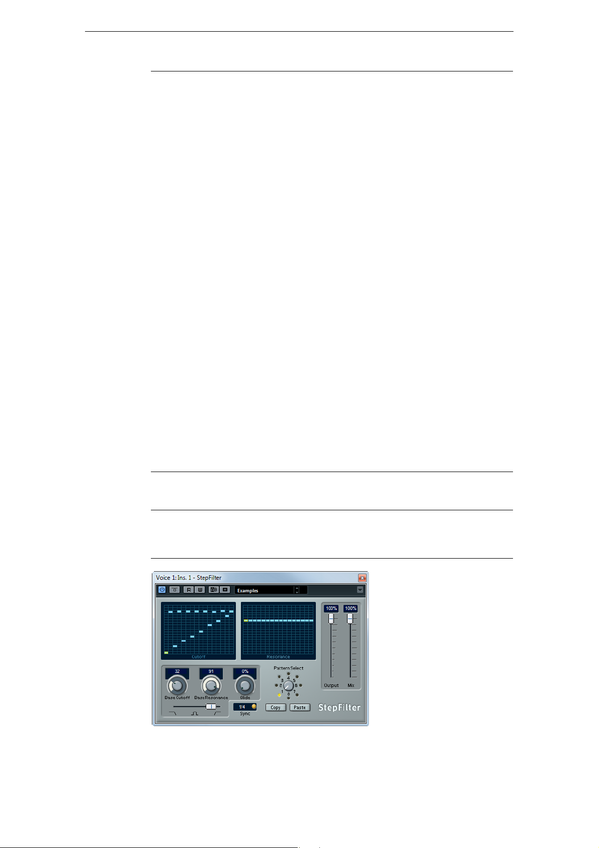
Filter Plug-ins
Parameter Description
Low Cut
Preview button
Spectrum Shows the spectrum before and after filtering.
Notch Freq Sets the frequency of the notch filter.
Notch Gain Adjusts the gain of the selected frequency. Use positive values to
Notch Gain
Invert button
Notch Q-Factor Sets the width of the notch filter.
Notch Preview button This button is located between the notch filter buttons and the
Notches buttons
(1, 2, 4, 8)
High Cut Freq
(3 to 20 kHz, or Off)
High Cut Slope
pop-up menu
High Cut Preview
button
This button is located between the “Low Cut Freq” button and the
graphical display. Use it to switch the filter to a complementary
high-cut filter. This deactivates any other filters, allowing you to
listen only to the frequencies you want to filter out.
identify the frequencies that you want to filter out.
Inverts the gain value of the notch filter. Use this button to filter out
unwanted noise. When looking for the frequency to omit, it
sometimes helps to boost it first (set the notch filter to positive
gain). After you have found it, you can use the Invert button to
cancel it out.
graphical display. Use it to create a band-pass filter with the peak
filter’s frequency and Q. This deactivates any other filters, allowing
you to listen only to the frequencies you want to filter out.
These buttons add additional notch filters to filter out harmonics.
Use this high-cut filter to eliminate high-frequency noise. The filter
is off when the curve point is moved all the way to the right.
Allows you to choose a slope value for the high-cut filter.
This button is located between the High Cut Freq button and the
graphical display. Use it to switch the filter to a complementary
low-cut filter. This deactivates any other filters, allowing you to
listen only to the frequencies you want to filter out.
StepFilter
Cubase LECubase AICubase
Elements
Included with
StepFilter is a pattern-controlled multimode filter that can create rhythmic, pulsating
filter effects.
– – X X X X –
Cubase
Artist
Cubase Nuendo NEK
63
The Included Effect Plug-ins
Page 64

Filter Plug-ins
General Operation
StepFilter can produce two simultaneous 16-step patterns for the filter cutoff and
resonance parameters, synchronized to the sequencer tempo.
Setting Step Values
• Setting step values is done by clicking in the pattern grid windows.
• Individual step entries can be freely dragged up or down the vertical axis, or
directly set by clicking in an empty grid box. By click-dragging left or right,
consecutive step entries are set at the pointer position.
• The horizontal axis shows the pattern steps 1 to 16 from left to right, and the
vertical axis determines the (relative) filter cutoff frequency and resonance settings.
The higher up on the vertical axis a step value is entered, the higher the relative
filter cutoff frequency or filter resonance setting.
• By starting playback and editing the patterns for the cutoff and resonance
parameters, you can hear how your filter patterns affect the sound source
connected to StepFilter.
Selecting New Patterns
• Created patterns are saved with the project, and up to 8 different cutoff and
resonance patterns can be saved internally.
Both the cutoff and resonance settings are saved together in the 8 pattern slots.
• Use the Pattern Selector below the Resonance grid to select a new pattern.
New patterns are all set to the same step value by default.
Using Pattern Copy and Paste to Create Variations
You can use the Copy and Paste buttons below the Pattern Selector to copy a pattern
to another pattern slot, which is useful for creating variations on a pattern.
• Select the pattern you wish to copy, click the Copy button, select another pattern
slot, and click Paste.
The pattern is copied to the new slot, and can now be edited to create variations
using the original pattern as a starting point.
StepFilter Parameters
The following parameters are available:
Parameter Description
Base Cutoff Sets the base filter cutoff frequency. Values set in the Cutoff grid
are relative to the Base Cutoff value.
Base Resonance Sets the base filter resonance. Values set in the Resonance grid
are relative to the Base Resonance value. Note that very high Base
Resonance settings can produce loud ringing effects at certain
frequencies.
Glide Applies glide between the pattern step values, causing values to
change more smoothly.
Filter mode Use this slider to select a filter mode: low-pass (LP), band-pass
(BP), or high-pass (HP) (from left to right).
Sync button When the Sync button to the right of the Sync pop-up menu is
activated (yellow), the pattern playback is synchronized with the
project tempo.
Sync pop-up menu
(1/1 to 1/32, straight,
triplet, or dotted)
Use this pop-up menu to set the pattern beat resolution, that is, the
note values the pattern plays in relation to the tempo.
64
The Included Effect Plug-ins
Page 65

Parameter Description
Output slider Sets the overall volume.
Mix slider Adjusts the mix between dry and processed signal.
ToneBooster
Filter Plug-ins
Cubase LECubase AICubase
Elements
Included with
ToneBooster is a filter that allows you to raise the gain in a selected frequency range.
It is particularly useful when inserted before AmpSimulator in the plug-in chain (see
“AmpSimulator” on page 10), greatly enhancing the tonal varieties available.
The following parameters are available:
Parameter Description
Tone Sets the center filter frequency.
Gain Adjusts the gain of the selected frequency range by up to 24 dB.
Width Sets the resonance of the filter.
Mode selector Sets the basic operational mode of the filter; Peak or Band Mode.
– X X X X X –
Cubase
Artist
Cubase Nuendo NEK
WahWah
Cubase LECubase AICubase
Elements
Included with
Side-chain
support
WahWah is a variable slope band-pass filter that can be auto-controlled by a sidechain signal (if supported, see table above) or via MIDI modeling the well-known
analog pedal effect. You can independently specify the frequency, width and the gain
for the Lo and Hi Pedal positions. The crossover point between the Lo and Hi Pedal
positions lies at 50.
– X X X X X –
– – – X X X –
Cubase
Artist
Cubase Nuendo NEK
65
The Included Effect Plug-ins
Page 66

Mastering Plug-ins
The following parameters are available:
Parameter Description
Pedal Controls the filter frequency sweep.
Pedal Control
(MIDI) pop-up
menu
Freq Lo/Hi Set the frequency of the filter for the Lo and Hi Pedal positions.
Width Lo/Hi Set the width (resonance) of the filter for the Lo and Hi Pedal
Gain Lo/Hi Set the gain of the filter for the Lo and Hi Pedal positions.
Filter Slope
selector
Ö If side-chaining is supported, the Pedal parameter can also be controlled from another
signal source via the side-chain input. The louder the signal, the more the filter
frequency (Pedal) is raised so that the plug-in acts as an auto-wha effect. For a
description of how to set up side-chain routing, see the Operation Manual.
Allows you to choose the MIDI controller that controls the plug-in.
Set this to “Automation” if you do not want to use MIDI realtime
control.
positions.
Allows you to choose between two filter slope values: 6 dB or 12 dB.
MIDI Control
For realtime MIDI control of the Pedal parameter, MIDI must be directed to the
WahWah plug-in.
• Whenever WahWah has been added as an insert effect (for an audio track or an
FX channel), it is available on the Output Routing pop-up menu for MIDI tracks.
If WahWah is selected on the Output Routing menu, MIDI data is directed to the
plug-in from the selected track.
Mastering Plug-ins
This section contains descriptions of the plug-ins in the “Mastering” category.
UV22HR
Included with
Cubase LECubase AICubase
Elements
– – X X X X –
Cubase
Artist
Cubase Nuendo NEK
The UV22HR is a dithering plug-in, based on an advanced algorithm developed by
Apogee. For an introduction to the concept of dithering, see the Operation Manual.
The following parameters are available:
Option Description
Bit Resolution The UV22HR supports dithering to multiple resolutions: 8, 16, 20 or
24 bits. Select the resolution by clicking the corresponding button.
Hi Try this first, it is the most all-round setting.
66
The Included Effect Plug-ins
Page 67

Option Description
!
Lo Applies a lower level of dither noise.
Auto black When this is activated, the dither noise is gated (muted) during silent
Dithering should always be applied post-fader on an output bus.
Modulation Plug-ins
This section contains descriptions of the plug-ins in the “Modulation” category.
AutoPan
Modulation Plug-ins
passages in the material.
Cubase LECubase AICubase
Elements
Included with
Side-chain
support
This is a simple auto-pan effect. It can use different waveforms to modulate the leftright stereo position (pan), either using tempo sync or manual modulation speed
settings.
The following parameters are available:
Parameter Description
Rate If tempo sync is on, this is where you specify the base note value for
Sync button The button below the Rate knob switches tempo sync on or off.
Width Sets the depth of the auto-pan effect.
Waveform Shape
selector
X X X X X X –
– – – X X X –
tempo-syncing the effect (1/1 to 1/32, straight, triplet, or dotted).
If tempo sync is off, the auto-pan speed can be set freely with the
Rate knob.
Allows you to select the modulation waveform. A sine and a triangle
waveform are available.
Cubase
Artist
Cubase Nuendo NEK
Ö If side-chaining is supported, the Width parameter can also be controlled from
another signal source via the side-chain input. For a description of how to set up sidechain routing, see the Operation Manual.
67
The Included Effect Plug-ins
Page 68

Chopper
Modulation Plug-ins
Cubase LECubase AICubase
Elements
Included with
Chopper is a combined tremolo and autopan effect. It can use different waveforms to
modulate the level (tremolo) or left-right stereo position (pan), either using tempo sync
or manual modulation speed settings.
The following parameters are available:
Parameter Description
Waveform buttons Set the modulation waveform.
Depth Sets the depth of the Chopper effect. This can also be set by clicking
Speed If tempo sync is on, this is where you specify the base note value for
Sync button The button above the Speed knob switches tempo sync on (button
Stereo/Mono
button
Mix Sets the level balance between the dry and the wet signal. If Chopper
X X X X X X –
in the graphical display.
tempo-syncing the effect (1/1 to 1/32, straight, triplet, or dotted).
Note that there is no note value modifier for this effect.
If tempo sync is off, the tremolo/auto-pan speed can be set freely
with the Speed knob.
lights up) or off.
Determines whether the Chopper works as an auto-panner (button
set to “Stereo”) or a tremolo effect (button set to “Mono”).
is used as a send effect, this should be set to the maximum value.
Cubase
Artist
Cubase Nuendo NEK
68
The Included Effect Plug-ins
Page 69

Chorus
Modulation Plug-ins
Cubase LECubase AICubase
Elements
Included with
Side-chain
support
This is a single-stage chorus effect. It works by doubling whatever is sent into it with a
slightly detuned version (see also
The following parameters are available:
Parameter Description
Rate If tempo sync is on, this is where you specify the base note value for
Sync button The button below the Rate knob switches tempo sync on or off.
Width Determines the depth of the chorus effect. Higher settings produce a
Waveform Shape
selector
Spatial Sets the stereo width of the effect. Turn clockwise for a wider stereo
Mix Sets the level balance between the dry and the wet signal. If Chorus
Delay Affects the frequency range of the modulation sweep by adjusting the
Filter Lo/Hi Allow you to roll off low and high frequencies of the effect signal.
X X X X X X –
– – – X X X –
“StudioChorus” on page 77).
tempo-syncing the chorus sweep (1/1 to 1/32, straight, triplet, or
dotted).
If tempo sync is off, the sweep rate can be set freely with the Rate
knob.
more pronounced effect.
Allows you to select the modulation waveform, altering the character
of the chorus sweep. A sine and a triangle waveform are available.
effect.
is used as a send effect, set this to the maximum value as you can
control the dry/effect balance with the send.
initial delay time.
Cubase
Artist
Cubase Nuendo NEK
Ö If side-chaining is supported, the modulation can also be controlled from another
signal source via the side-chain input. When the side-chain signal exceeds the
threshold, the modulation is controlled by the side-chain signal’s envelope. For a
description of how to set up side-chain routing, see the Operation Manual.
69
The Included Effect Plug-ins
Page 70

Cloner
Modulation Plug-ins
Cubase LECubase AICubase
Elements
Included with
The Cloner plug-in adds up to four detuned and delayed voices to the signal, for rich
modulation and chorus effects.
The following parameters are available:
Parameter Description
Voices Allows you to select the number of voices (up to four). For each
Spatial Spreads the added voices across the stereo spectrum. Turn
Mix Sets the level balance between the dry and the wet signal. If Cloner is
Output Allows you to reduce or increase the output gain by up to 12 dB.
Detune slider
1 to 4
Delay slider
1 to 4
Detune Governs the overall depth of the detuning for all voices. If this is set to
Natural button By clicking the Natural button below the Detune knob, you can
Detune –
Humanize
Static Detune
button
Delay Governs the overall depth of the delay for all voices. If set to zero, no
– – – – X X –
added voice, a Detune and a Delay slider are added in the right half of
the panel.
clockwise for a deeper stereo effect.
used as a send effect, set this to the maximum value as you can
control the dry/effect balance with the send.
Controls the relative detune amount for each voice. Positive and
negative values can be set, from -100 to 100. A value of zero means
no detune for that voice.
Controls the relative delay amount for each voice. A value of zero
means no delay for that voice.
zero, no detuning takes place, regardless of the Detune slider
settings.
change the pitch algorithm.
Controls the amount of detune variation when Static Detune is
deactivated. With Humanize, the detune is constantly modulated for a
more natural effect. The value range is from 0 to 100 (strongest
detune variation).
Use this button to activate/deactivate the Static Detune function. If
activated, the set detune amount is static, and the Humanize knob is
grayed out.
delay takes place regardless of the Delay slider settings.
Cubase
Artist
Cubase Nuendo NEK
70
The Included Effect Plug-ins
Page 71

Flanger
Modulation Plug-ins
Parameter Description
Delay – Humanize Controls the amount of delay variation when Static Delay is
deactivated. With Humanize, the delay is constantly modulated for a
more natural effect. The value range is from 0 to 100 (strongest delay
variation).
Static Delay button Use this button to activate/deactivate the Static Delay function. If
activated, the set delay amount is static, and the Humanize knob is
grayed out.
Cubase LECubase AICubase
Elements
Included with
Side-chain
support
Flanger is a classic flanger effect with added stereo enhancement.
The following parameters are available:
Parameter Description
Rate If tempo sync is on, this is where you specify the base note value for
Sync button The button below the Rate knob switches tempo sync on or off.
Range Lo/Hi Set the frequency boundaries for the flanger sweep.
Feedback Determines the character of the flanger effect. Higher settings
Spatial Sets the stereo width of the effect. Turn clockwise for a wider stereo
Mix Sets the level balance between the dry and the wet signal. If Flanger
Waveform Shape
selector
Delay Affects the frequency range of the modulation sweep by adjusting the
X X X X X X –
– – – X X X –
tempo-syncing the flanger sweep (1/1 to 1/32, straight, triplet, or
dotted).
If tempo sync is off, the sweep rate can be set freely with the Rate
knob.
produce a more metallic sounding sweep.
effect.
is used as a send effect, set this to the maximum value as you can
control the dry/effect balance with the send.
Allows you to select the modulation waveform, altering the character
of the flanger sweep. A sine and a triangle waveform are available.
initial delay time.
Cubase
Artist
Cubase Nuendo NEK
71
The Included Effect Plug-ins
Page 72

Metalizer
Modulation Plug-ins
Parameter Description
Manual knob Allows you to change the sweep position manually when the Manual
button is deactivated. The value range is from 0 to 100.
Manual button Use this button to activate/deactivate the Manual function. If
activated, the flanger sweep is static, that is, no modulation takes
place.
Filter Lo/Hi Allow you to roll off low and high frequencies of the effect signal.
Ö If side-chaining is supported, the modulation can also be controlled from another
signal source via the side-chain input. When the side-chain signal exceeds the
threshold, the modulation is controlled by the side-chain signal’s envelope. For a
description of how to set up side-chain routing, see the Operation Manual.
Cubase LECubase AICubase
Elements
Included with
Metalizer feeds the audio signal through a variable frequency filter, with tempo sync or
time modulation and feedback control.
The following parameters are available:
Parameter Description
Feedback The higher the value, the more metallic the sound.
Sharpness Governs the character of the filter effect. The higher the value, the
Tone Governs the feedback frequency. The effect of this is more noticeable
On button Turns filter modulation on and off. When turned off, Metalizer works
Mono button When this is activated, the output of Metalizer is mono.
Speed If tempo sync is on, this is where you specify the base note value for
Sync button The button above the Speed knob switches tempo sync on (button
– X X X X X –
narrower the affected frequency area, producing a sharper sound and
a more pronounced effect.
with high Feedback settings.
as a static filter.
tempo-syncing the effect (1/1 to 1/32, straight, triplet, or dotted).
Note that there is no note value modifier for this effect.
If tempo sync is off, the modulation speed can be set freely with the
Speed knob.
lights up) or off.
Cubase
Artist
Cubase Nuendo NEK
72
The Included Effect Plug-ins
Page 73

Phaser
Modulation Plug-ins
Parameter Description
Output slider Sets the overall volume.
Mix slider Sets the level balance between the dry and the wet signal. If Metalizer
is used as a send effect, set this to the maximum value as you can
control the dry/effect balance with the send.
Cubase LECubase AICubase
Elements
Included with
Side-chain
support
Phaser produces the well-known swooshing phasing effect with additional stereo
enhancement.
The following parameters are available:
Parameter Description
Rate If tempo sync is on, this is where you specify the base note value for
Sync button The button below the Rate knob switches tempo sync on or off.
Width Determines the width of the modulation effect between higher and
Feedback Determines the character of the phaser effect. Higher settings
Spatial When using multi-channel audio, the Spatial parameter creates a 3-
Mix Sets the level balance between the dry and the wet signal. If Phaser
Manual knob Allows you to change the sweep position manually when the Manual
X X X X X X –
– – – X X X –
tempo-syncing the phaser sweep (1/1 to 1/32, straight, triplet, or
dotted).
If tempo sync is off, the sweep rate can be set freely with the Rate
knob.
lower frequencies.
produce a more pronounced effect.
dimensional impression by delaying modulation in each channel.
is used as a send effect, set this to the maximum level as you can
control the dry/effect balance with the send.
button is deactivated. The value range is from 0 to 100.
Cubase
Artist
Cubase Nuendo NEK
73
The Included Effect Plug-ins
Page 74

Parameter Description
Manual button Use this button to activate/deactivate the Manual function. If
Filter Lo/Hi Allow you to roll off low and high frequencies of the effect signal.
Ö If side-chaining is supported, the modulation can also be controlled from another
signal source via the side-chain input. When the side-chain signal exceeds the
threshold, the modulation is controlled by the side-chain signal’s envelope. For a
description of how to set up side-chain routing, see the Operation Manual.
RingModulator
Modulation Plug-ins
activated, the flanger sweep is static, that is, no modulation takes
place.
Cubase LECubase AICubase
Elements
Included with
RingModulator can produce complex, bell-like enharmonic sounds. Ring modulators
work by multiplying two audio signals. The ring modulated output contains added
frequencies generated by the sum of, and the difference between, the frequencies of
the two signals.
RingModulator has a built-in oscillator that is multiplied with the input signal to
produce the effect.
The following parameters are available:
– X X X X X –
Cubase
Artist
Cubase Nuendo NEK
Parameter Description
Oscillator –
LFO
Amount
Oscillator –
Env.
Amount
Oscillator –
Waveform buttons
Oscillator –
Range
slider
Controls how much the oscillator frequency is affected by the LFO.
Controls how much the oscillator frequency is affected by the
envelope (which is triggered by the input signal). Positive and
negative values can be set, with center position representing no
modulation. Left of center, a loud input signal decreases the
oscillator pitch, whereas right of center the oscillator pitch
increases when fed a loud input.
Allows you to select the oscillator waveform; square, sine, saw, or
triangle.
Determines the frequency range of the oscillator in Hz.
The Included Effect Plug-ins
74
Page 75

Modulation Plug-ins
Parameter Description
Oscillator –
Frequency
Oscillator – Roll-Off Attenuates high frequencies in the oscillator waveform, to soften
LFO – Speed Sets the LFO speed.
LFO – Env. Amount Controls how much the input signal level – via the envelope
LFO – Waveform Allows you to select the LFO waveform; square, sine, saw, or
LFO – Invert Stereo Inverts the LFO waveform for the right channel of the oscillator,
Envelope Generator
section – Attack and
Decay
Lock L<R button When this button is enabled, the L and R input signals are merged,
Output slider Sets the overall volume.
Mix slider Adjusts the mix between dry and processed signal.
Sets the oscillator frequency ±2 octaves within the selected range.
the overall sound. This is best used when harmonically rich
waveforms are selected (square or saw, for example).
generator – affects the LFO speed. Positive and negative values
can be set, at 0
loud input signal slows down the LFO, whereas positive values
speed it up at loud input signals.
triangle.
which produces a wider stereo perspective for the modulation.
The Envelope Generator section controls how the input signal is
converted to envelope data, which can then be used to control
oscillator pitch and LFO speed. It has two main controls:
Attack controls how fast the envelope output level rises in response
to a rising input signal.
Decay controls how fast the envelope output level falls in response
to a falling input signal.
and produce the same envelope output level for both oscillator
channels. When disabled, each channel has its own envelope,
which affects the two channels of the oscillator independently.
% no modulation is applied. With negative values, a
Rotary
Cubase LECubase AICubase
Elements
Included with
The Rotary plug-in simulates the classic effect of a rotating speaker. A rotary speaker
cabinet features speakers rotating at variable speeds to produce a swirling chorus
effect, commonly used with organs. Rotary features all the parameters associated with
the real thing.
– – X X X X –
Cubase
Artist
Cubase Nuendo NEK
75
The Included Effect Plug-ins
Page 76

Modulation Plug-ins
The following parameters are available:
Parameter Description
Speed selector
(Stop/Slow/Fast)
Speed Change
Mode
Speed Mod When the Slow/Fast setting is set to variable control, this allows you
MIDI controller
pop-up menu
Overdrive Applies a soft overdrive or distortion.
CrossOver Sets the crossover frequency (200 to 3000 Hz) between the low and
Horn – Slow Allows for a fine adjustment of the high rotor Slow speed.
Horn – Fast Allows for a fine adjustment of the high rotor Fast speed.
Horn – Accel. Allows for a fine adjustment of the high rotor acceleration time.
Horn – Amp Mod Controls the high rotor amplitude modulation.
Horn – Freq Mod Controls the high rotor frequency modulation.
Bass – Slow Allows for a fine adjustment of the low rotor Slow speed.
Bass – Fast Allows for a fine adjustment of the low rotor Fast speed.
Bass – Accel. Allows for a fine adjustment of the low rotor acceleration time.
Bass – Amp Mod Adjusts the modulation depth of the amplitude.
Bass – Level Adjusts the overall bass level.
Microphones –
Phase
Microphones –
Angle
Microphones –
Distance
Output Adjusts the overall output level.
Mix Adjusts the mix between dry and processed signal.
Allows you to control the speed of the Rotary in three steps.
Allows you to select whether the Slow/Fast setting is a switch (left)
or a variable control (right). When switch mode is selected and
Pitchbend is the controller, the speed switches with an up or down
flick of the bender. Other controllers switch at MIDI value 64.
to select the rotary speed, from 0 (Stop) to 100 (Fast).
Allows you to choose the MIDI controller that controls the plug-in.
Set this to “Automation” if you do not want to use MIDI realtime
control.
high frequency loudspeakers.
Adjusts the phasing amount in the sound of the high rotor.
Sets the simulated microphone angle. 0 = mono, 180 = a mic on
each side.
Sets the simulated microphone distance from the speaker in inches.
Directing MIDI to the Rotary
For realtime MIDI control of the Speed parameter, MIDI must be directed to the
Rotary.
• Whenever Rotary has been added as an insert effect (for an audio track or an
FX
channel), it is available on the Output Routing pop-up menu for MIDI tracks.
If Rotary is selected on the Output Routing menu, MIDI is directed to the plug-in
from the selected track.
76
The Included Effect Plug-ins
Page 77

StudioChorus
Modulation Plug-ins
Cubase LECubase AICubase
Elements
Included with
Side-chain
support
The StudioChorus plug-in is a two stage chorus effect which adds short delays to the
signal and pitch modulates the delayed signals to produce a doubling effect. The two
separate stages of chorus modulation are completely independent and are processed
serially (cascaded).
For each stage the following parameters are available:
– – – – X X –
– – – – X X –
Cubase
Artist
Cubase Nuendo NEK
Parameter Description
Rate If tempo sync is on, this is where you specify the base note value for
tempo-syncing the chorus sweep (1/1 to 1/32, straight, triplet, or
dotted).
If tempo sync is off, the sweep rate can be set freely with the Rate
knob.
Sync button The button below the Rate knob switches tempo sync on or off.
Width Determines the depth of the chorus effect. Higher settings produce
a more pronounced effect.
Waveform Shape
selector
Spatial Sets the stereo width of the effect. Turn clockwise for a wider
Mix Sets the level balance between the dry and the wet signal. If
Delay Affects the frequency range of the modulation sweep by adjusting
Filter Lo/Hi Allow you to roll off low and high frequencies of the effect signal.
Ö If side-chaining is supported, the modulation can also be controlled from another
signal source via the side-chain input. When the side-chain signal exceeds the
threshold, the modulation is controlled by the side-chain signal’s envelope. For a
description of how to set up side-chain routing, see the Operation Manual.
Allows you to select the modulation waveform, altering the
character of the chorus sweep. A sine and a triangle waveform are
available.
stereo effect.
StudioChorus is used as a send effect, set this to the maximum
value as you can control the dry/effect balance with the send.
the initial delay time.
77
The Included Effect Plug-ins
Page 78

Tranceformer
Modulation Plug-ins
Cubase LECubase AICubase
Elements
Included with
Tranceformer is a ring modulator effect, in which the incoming audio is ring modulated
by an internal, variable frequency oscillator, producing new harmonics. A second
oscillator can be used to modulate the frequency of the first oscillator, in sync with the
Song tempo if needed.
The following parameters are available:
Parameter Description
Waveform buttons Allow you to select a pitch modulation waveform.
Tone Sets the frequency (pitch) of the modulating oscillator (1 to 5000 Hz).
Depth Governs the depth of the pitch modulation.
Speed If tempo sync is on, this is where you specify the base note value for
Sync button The button above the Speed knob switches tempo sync on (button
On button Turns modulation of the pitch parameter on or off.
Mono button Governs whether the output is stereo or mono.
Output slider Adjusts the output level of the effect.
Mix slider Sets the level balance between the dry and the wet signal.
– X X X X X –
tempo-syncing the effect (1/1 to 1/32, straight, triplet, or dotted).
Note that there is no note value modifier for this effect.
If tempo sync is off, the modulation speed can be set freely with the
Speed knob.
lights up) or off.
Cubase
Artist
Cubase Nuendo NEK
Ö Note that clicking and dragging in the display allows you to adjust the Tone and Depth
parameters at the same time!
78
The Included Effect Plug-ins
Page 79

Tremolo
Modulation Plug-ins
Cubase LECubase AICubase
Elements
Included with
Side-chain
support
Tremolo produces amplitude (volume) modulation. The following parameters are
available:
Parameter Description
Rate If tempo sync is on, this is where you specify the base note value for
Sync button The button below the Rate knob switches tempo sync on or off.
Depth Governs the depth of the amplitude modulation.
Spatial Adds a stereo effect to the modulation.
Output Adjusts the output volume.
X X X X X X –
– – – X X X –
tempo-syncing the effect (1/1 to 1/32, straight, triplet, or dotted).
If tempo sync is off, the modulation speed can be set freely with the
Rate knob.
Cubase
Artist
Cubase Nuendo NEK
Ö If side-chaining is supported, the modulation can also be controlled from another
signal source via the side-chain input. When the side-chain signal exceeds the
threshold, the modulation is controlled by the side-chain signal’s envelope. For a
description of how to set up side-chain routing, see the Operation Manual.
79
The Included Effect Plug-ins
Page 80

Vibrato
Modulation Plug-ins
Cubase LECubase AICubase
Elements
Included with
Side-chain
support
The Vibrato plug-in produces pitch modulation. The following parameters are
available:
Parameter Description
Rate If tempo sync is on, this is where you specify the base note value for
Sync button The button below the Rate knob switches tempo sync on or off.
Depth Governs the depth of the pitch modulation.
Spatial Adds a stereo effect to the modulation.
X X X X X X –
– – – X X X –
tempo-syncing the effect (1/1 to 1/32, straight, triplet, or dotted).
If tempo sync is off, the modulation speed can be set freely with the
Rate knob.
Cubase
Artist
Cubase Nuendo NEK
Ö If side-chaining is supported, the modulation can also be controlled from another
signal source via the side-chain input. When the side-chain signal exceeds the
threshold, the modulation is controlled by the side-chain signal’s envelope. For a
description of how to set up side-chain routing, see the Operation Manual.
80
The Included Effect Plug-ins
Page 81

Pitch Shift Plug-ins
This section contains descriptions of the plug-ins in the “Pitch Shift” category.
Octaver
Pitch Shift Plug-ins
Cubase LECubase AICubase
Elements
Included with
This plug-in can generate two additional voices that track the pitch of the input signal
one octave and two octaves below the original pitch, respectively. Octaver is best
used with monophonic signals.
The following parameters are available:
Parameter Description
Direct Adjusts the mix of the original signal and the generated voices. A
Octave 1 Adjusts the level of the signal that is generated one octave below the
Octave 2 Adjusts the level of the signal that is generated two octaves below
– X X X X X –
value of 0 means only the generated and transposed signal is heard.
By raising this value, more of the original signal is heard.
original pitch. A setting of 0 means that the voice is muted.
the original pitch. A setting of 0 means that the voice is muted.
Cubase
Artist
Cubase Nuendo NEK
81
The Included Effect Plug-ins
Page 82

Pitch Correct
Pitch Shift Plug-ins
Cubase LECubase AICubase
Elements
Included with
Pitch Correct automatically detects, adjusts and fixes slight pitch and intonation
inconsistencies in monophonic vocal and instrumental performances in realtime. The
advanced algorithms of this plug-in preserve the formants of the original sound thus
allowing for natural sounding pitch correction without the typical Mickey Mouse effect.
– – X X X X –
Cubase
Artist
Cubase Nuendo NEK
Furthermore, you can use Pitch Correct creatively. You can create backing vocals, for
example, by modifying the lead vocals or vocoder sounds by using extreme values.
You can use an external MIDI controller, a MIDI track or the virtual keyboard to play a
note or a scale of target pitches that determine the current scale notes to which the
audio is shifted. This allows you to change your audio in a very quick and easy way,
which is extremely useful for live performances. In the keyboard display, the original
audio is displayed in blue while the changes are displayed in orange.
The following parameters are available:
Parameter Description
Correction – Speed Determines the smoothness of the pitch change. Higher values
cause the pitch shift to occur immediately. 100 is a very drastic
setting that is designed mainly for special effects (for example, the
famous Cher effect).
Correction –
Tolerance
Correction –
Transpose
(-12 to 12)
Determines the sensitivity of analysis. A low Tolerance value lets
Pitch Correct find pitch changes quickly. When the Tolerance value
is high, pitch variations in the audio (for example, vibrato) are not
immediately interpreted as note changes.
With this parameter you can adjust (or retune) the pitch of the
incoming audio in semitone steps. You can set positive and negative
values from -12 to 12. A value of zero means that the signal is not
transposed.
82
The Included Effect Plug-ins
Page 83

Pitch Shift Plug-ins
Parameter Description
Scale Source –
Internal
Scale Source –
External MIDI Scale
Scale Source –
External MIDI Note
Formant – Shift
(-60 to 60)
Formant – Optimize
(General, Male,
Female)
Formant –
Preservation
(On/Off)
Master Tuning Detunes the output signal. The default setting is 440 Hz.
If you choose the Internal option from the Scale Source pop-up
menu, you can use the pop-up menu next to it to decide to which
scale the source audio is adapted. The following options are
available:
Chromatic: The audio is pitched to the closest semitone.
Major/Minor: The audio is pitched to the major/minor scale specified
in the pop-up menu to the right. This is reflected on the keyboard
display.
Custom: The audio is pitched to the notes that you specify by
clicking keys on the keyboard display. To reset the keyboard, click
the orange line below the display.
Select this option if you want the audio to be shifted to a scale of
target pitches, using an external MIDI controller, the Virtual Keyboard
or a MIDI track.
Note that you have to assign the audio track as the output of your
MIDI track and that the Speed parameter has to be set to a value
other than Off.
Select this option if you want the audio to be shifted to a target note,
using an external MIDI controller, the Virtual Keyboard or a MIDI
track.
Note that you have to assign the audio track as the output of your
MIDI track and that the Speed parameter has to be set to a value
other than Off.
Changes the natural timbre, that is, the characteristic frequency
components of the source audio.
Allows you to specify the sound characteristics of the sound
sources. While General is the default setting, Male is designed for
low pitches and Female for high pitches.
When this parameter is set to Off, formants are raised and lowered
with the pitch, provoking strange vocal effects. Higher pitch
correction values result in Mickey Mouse effects, lower pitch
correction values in Monster sounds.
When this parameter is set to On, the formants are kept, maintaining
the character of the audio.
83
The Included Effect Plug-ins
Page 84

PitchDriver
Pitch Shift Plug-ins
Cubase LECubase AICubase
Elements
Included with
PitchDriver was created for sound design purposes in postproduction. This plug-in
can be used for extreme up or down pitching of voices or effect samples (for example,
to create eerie monster sounds). Shifting the pitch with this plug-in does not keep the
formants.
The following parameters are available:
Parameter Description
Detune Lets you detune the pitch of the incoming audio. Positive and
Mix Sets the level balance between the dry and the wet signal.
Spatial Creates an ambience effect. It introduces a light pitch offset to the
Output Adjusts the output volume.
– – – – – X –
negative values can be set.
incoming signal. Different offset values are used for the individual
input channels in order to create a panorama effect.
Note that the created panorama effect can be unstable. For a stable
panorama, turn off the Spatial parameter. In that case the incoming
signals are summed up to a mono signal.
Cubase
Artist
Cubase Nuendo NEK
Ö To avoid hearing artifacts, it is recommended to set the ASIO buffer for your audio
card to at least 128 samples. The buffer size can be set on the card driver’s control
panel (opened via the Device Setup dialog).
84
The Included Effect Plug-ins
Page 85

Reverb Plug-ins
This section contains descriptions of the plug-ins in the “Reverb” category.
REVerence
Reverb Plug-ins
Cubase LECubase AICubase
Elements
Included with
REVerence is a convolution tool that allows you to apply room characteristics (reverb)
to the audio. This is done by processing the audio signal according to an impulse
response – a recording of an impulse in a room or another location that recreates the
characteristics of the room. As a result, the processed audio sounds as if it were
played in the same location. Included with the plug-in are top quality samples of real
spaces to create reverberation.
Ö REVerence can be very demanding in terms of RAM. This is because the impulse
responses that you load into the program slots are preloaded into RAM to guarantee
artifact-free switching between programs. Therefore, you should always load only
those programs that you need for a given task.
– – – – X X –
Cubase
Artist
Cubase Nuendo NEK
Using the Program Matrix
A program is the combination of an impulse response and its settings. These include
reverb settings (see
“Making EQ Settings” on page 89), pictures (see “Loading Pictures” on page 90),
and output settings (see “Making Output Settings” on page 90). The program matrix
allows you to load programs and to view the name of the current program, that is, the
impulse response (see
“Changing the Reverb Settings” on page 87), EQ settings (see
“Working with Custom Impulse Responses” on page 91).
85
The Included Effect Plug-ins
Page 86

Reverb Plug-ins
The following parameters are available:
Parameter Description
Program name In the upper left corner of the plug-in panel, either the name of the
loaded impulse response file or the name of the program is shown.
After loading an impulse response, its number of channels and the
length in seconds are displayed for a few seconds.
Browse button This button opens a browser window showing the available
programs. When you select a program in the browser, it is loaded into
the active program slot. To be able to filter the list of impulse
responses in the browser window, for example, by room type or the
number of channels, you can activate the Filters section (by clicking
the “Set Up Window Layout” button at the bottom left of the window).
Import button Click this button to load your own impulse response files from disk. The
files should have a maximum length of 10 seconds. Longer files are
automatically cut. For more information, see
Impulse Responses” on page 91.
Program slots
(1 to 36)
Smooth Parameter
Changes button
Store button Stores the active impulse response and its settings as a program.
Erase button Removes the selected program from the matrix.
Use these slots to load all the impulse responses (programs) that you
want to work with in a session. The selected program slot is indicated
by a white frame. Used slots are shown in a different color. Doubleclicking an empty program slot opens a browser window, showing
the available programs. Clicking a used program slot recalls the
corresponding program and loads it into REVerence. When you move
the mouse over a used slot, the corresponding program name is
displayed below the active program name.
The “Smooth Parameter Changes” button is located between the
program slots and the Store/Erase buttons. If it is activated, a
crossfade is performed when switching programs.
Leave this button deactivated while looking for a suitable program or
an appropriate setting for an impulse response. Once you have set up
the program matrix to your liking, activate the button to avoid hearing
artifacts when switching between programs.
“Working with Custom
Programs vs. Presets
You can save your REVerence settings as VST plug-in presets or programs.
Both presets and programs use the file extension .vstpreset and appear in the same
category in the MediaBay (Plug-In Presets), but they are represented by different
icons:
Icon Description
A REVerence preset contains all settings and parameters for the plug-in,
that is, all the loaded impulse responses along with their parameter
settings and positions in the program matrix. Presets are loaded via the
Presets pop-up menu at the top of the plug-in panel.
A REVerence program only contains the settings related to a single
impulse response. Programs are loaded and managed via the program
matrix.
86
The Included Effect Plug-ins
Page 87

Reverb Plug-ins
Δ
Presets
Presets are useful in the following situations:
• When you want to save a complete setup with different impulse responses for later
use (for example, different setups for explosion sounds that can be reused for
other scenes or movies).
• When you want to save different parameter sets for the same impulse response so
that you can later choose the set that best suits your needs.
Programs
Programs offer the following advantages:
• Up to 36 programs can be loaded into the program matrix for instant recall.
• A program provides a quick and easy way to save and recall a subset of the plug-
in parameters (that is, the settings for a single impulse response), allowing for
short loading times.
• When automating a project and loading a REVerence program, only one
automation event is written.
If you load a plug-in preset instead (which contains a lot more settings than a
program), a lot of unnecessary automation data (for the settings that you did not
use) is written.
Setting up Programs
Proceed as follows:
1. In the program matrix, click on a program slot to select it.
A blinking white frame indicates that this program slot is selected.
2. Click the Browse button or click the empty slot again to load one of the included
programs.
You can also import a new impulse response file, see “Importing Impulse
Responses” on page 91.
3. In the browser that appears, select the program containing the impulse response
that you want to use and click OK.
The name of the loaded impulse response is shown in the upper left corner of the
REVerence panel.
4. Set up the REVerence parameters as needed and click the Store button to save
the impulse response with the current settings as a new program.
5. Set up as many programs as you need (up to 36) by following the steps above.
Ö If you want to use your set of programs in other projects, save your settings as a plug-
in preset using the Presets pop-up menu at the top of the plug-in panel.
Changing the Reverb Settings
The reverb settings allow you to change the characteristics of the room.
The following parameters are available:
Parameter Description
Main All values shown in the top row are for all speakers except the LFE.
Rear
If you are working with surround tracks up to 5.1, you can use this
row to set up an offset for the rear channels.
87
The Included Effect Plug-ins
Page 88

Reverb Plug-ins
Parameter Description
Auto Gain button When this button is activated, the impulse response is automatically
normalized.
Reverse button Reverses the impulse response.
Pre-Delay Controls the amount of time between the dry signal and the onset of
the reverb. With higher pre-delay values you can simulate larger
rooms.
Time Scaling Controls the reverb time.
Size Determines the size of the simulated room.
Level A level control for the impulse response. This governs the volume of
the reverb.
ER Tail Split Sets a split point between the early reflections and the tail, allowing
you to determine where the reverb tail begins. A value of 60 means
that the early reflections are heard for 60
ER Tail Mix Allows you to set up the relation of early reflections and tail. Values
above 50 attenuate the early reflections and values below 50
attenuate the tail.
ms.
The Impulse Response Display
The Display section allows you to view the impulse response details and to change
the length of the response (trimming).
The following parameters are available:
Parameter Description
Play button/
Time Scaling
wheel
Time Domain
display
Spectrogram
display
Information display Shows additional information, for example, the name of the program
When clicking the play button to apply the loaded impulse response,
a short click is played. This provides a neutral test sound that makes
it easier for you to know how different settings influence the reverb
characteristics.
The Time Scaling wheel lets you adjust the reverb time.
Shows the waveform of the impulse response.
Shows the analyzed spectrum of the impulse response. Time is
displayed along the horizontal axis, frequency along the vertical axis,
and volume is represented by the color.
and the loaded impulse response, the number of channels, the length,
and Broadcast Wave File information.
88
The Included Effect Plug-ins
Page 89

Parameter Description
Activate Impulse
Trimming button
Trim slider Allows you to trim the start and end of the impulse response. Drag
Making EQ Settings
In the Equalizer section you can tune the sound of the reverb.
Reverb Plug-ins
Use this button at the bottom right of the Impulse display section to
activate impulse trimming. The Trim slider is shown below the Impulse
display.
the front handle to trim the start of the impulse response, or the end
handle to trim the reverb tail. You can also use the mouse wheel for
trimming. Note that the impulse response is cut without any fading.
The following parameters are available:
Parameter Description
EQ curve display Shows the EQ curve. You can use the EQ parameters below the
display to change the EQ curve, or modify the curve manually by
dragging the curve points.
Activate EQ button This button to the right of the EQ parameters activates the EQ for
the effect plug-in.
Low Shelf On button Activates the low shelf filter that boosts or attenuates frequencies
below the cutoff frequency by the specified amount.
Low Freq
(20 to 500)
Low Gain
(-24 to +24)
Mid Peak On button Activates the mid peak filter that creates a peak or notch in the
Mid Freq
(100 to 10000)
Mid Gain
(-12 to +12)
Hi Shelf On button Activates the high shelf filter that boosts or attenuates frequencies
Hi Freq
(5000 to 20000)
Hi Gain
(-24 to +24)
Sets the frequency of the low band.
Sets the amount of attenuation/boost for the low band.
frequency response.
Sets the center frequency of the mid band.
Sets the amount of attenuation/boost for the mid band.
above the cutoff frequency by the specified amount.
Sets the frequency of the high band.
Sets the amount of attenuation/boost for the high band.
89
The Included Effect Plug-ins
Page 90

Loading Pictures
In the Pictures section you can load graphics files to illustrate the setting, for example,
the recording location or microphone arrangement of the loaded impulse response.
Up to five pictures can be loaded.
The following parameters are available:
Parameter Description
Add button Opens a file dialog where you can navigate to the graphics file that
Next button If several pictures are loaded, you can click this button to display the
Remove button Deletes the active picture. Note that this does not remove the
Reverb Plug-ins
you want to import. JPG, GIF, and PNG file formats are supported.
next image.
graphics file from your hard disk.
Ö Pictures are only referenced by the plug-in and are not copied to the project folder.
Making Output Settings
In the Output section you can control the overall level and determine the dry/wet mix.
The following parameters are available:
Parameter Description
Output activity
meter
Output slider Adjusts the overall output level.
Out
(-24 to +12)
Mix
(0 to 100)
Indicates the overall level of the impulse response and its settings.
Raises or lowers the signal output of the plug-in.
Sets the level balance between the dry and the wet signal.
• To lock the dry/wet balance while browsing through the available presets and
programs, activate the Lock button (padlock symbol) next to the Mix parameter.
90
The Included Effect Plug-ins
Page 91

Working with Custom Impulse Responses
In addition to working with the impulse responses included with REVerence, you can
import your own impulse responses and save these as programs or presets. WAVE
and AIFF files with a mono, stereo, true-stereo, or multi-channel (up to 5.0)
configuration are supported. If a multi-channel file contains an LFE channel, this
channel is ignored.
REVerence uses the same channel width as the track it is inserted on. When
importing impulse response files with more channels than the corresponding track,
the plug-in only reads as many channels as needed. If the impulse response file
contains fewer channels than the track, REVerence generates the missing channels
(for example, the center channel as a sum of the left and right channels). If the rear
channels are missing (when importing a stereo response file onto a 4.0 track, for
example), the left and right channels are also used for the rear channels. In this case
you can use the Rear offset parameter to create more spatiality.
Importing Impulse Responses
To import impulse responses, proceed as follows:
1. In the program matrix, click the Import button.
2. Navigate to the file that you want to import, and click Open.
The file is loaded into REVerence. The channels from an interleaved file are
imported in the same order as in other areas of the program (for example, the VST
Connections window), see below.
Reverb Plug-ins
3. Make the appropriate settings and add a picture, if available.
Pictures residing in the same folder as the impulse response file or in the parent
folder are automatically found and displayed.
4. Click the Store button to save the impulse response and its settings as a program.
That way you can recall the setup at any time.
The program slot turns blue, indicating that a program is loaded.
Ö When saving a program, the impulse response file itself is only referenced. It still
resides in the same location as before and is not modified in any way.
5. Repeat these steps for any impulse response files that you want to work with.
REVerence reads input channels in the following order:
No. of input
channels
1 L
2 L/R
3 L/R/C
4 L/R/LS/RS (if inserted on a track with a 4.0 channel configuration,
4 LL/LR/RL/RR (if inserted on a track with a stereo configuration, see
5 L/R/C/LS/RS
6 L/R/C/LFE/LS/RS (LFE is being ignored.)
Channel order in REVerence
see below)
below)
True Stereo
Impulse responses recorded as trues-stereo files enable you to create a very realistic
impression of the corresponding room. REVerence can only process true-stereo
impulse response files with the following channel configuration (in exactly that order):
LL, LR, RL, RR.
91
The Included Effect Plug-ins
Page 92

Reverb Plug-ins
The channels are defined as follows:
Channel The signal from this source… …was recorded with this
microphone
LL left source left microphone
LR left source right microphone
RL right source left microphone
RR right source right microphone
Ö If your true-stereo impulse responses are only available as separate mono files, you
can use the Export Audio Mixdown function to create REVerence compliant
interleaved files (see the Operation Manual).
By default, REVerence automatically works in true-stereo mode when the plug-in is
inserted on a stereo track and you load a 4-channel impulse response.
Therefore, if you are working with surround files, that is, 4-channel impulse responses
recorded with a Quadro configuration (L/R, LS/RS), you need to insert the plug-in on
an audio track with a 4.0 configuration. On a stereo track these files would be
processed in true-stereo mode, too.
So how can you prevent REVerence from unintentionally processing surround files in
true-stereo mode? The answer is a “Recording Method” attribute that can be written
to the iXML chunk of the corresponding impulse response file. Whenever you load an
impulse response with a 4-channel configuration on a stereo track, REVerence
searches the iXML chunk of the file. If the plug-in finds the Recording Method
attribute, the following happens:
• If the attribute is set to “TrueStereo”, the plug-in works in true-stereo mode.
• If the attribute is set to “A/B” or “Quadro”, the plug-in works in normal stereo mode
and processes only the L/R channels of the surround file.
Ö You can use the Attribute Inspector in the MediaBay to tag your own impulse
response files with the Recording Method attribute. For more information, see the
Operation Manual.
Relocating Content
Once you have imported your own impulse responses in REVerence you can
comfortably work with them on your computer. But what if you need to transfer your
content to another computer, for example because you work sometimes with a PC
and sometimes with a notebook, or you need to hand over a project to a colleague in
the studio?
The factory content is not a problem since it is also present on the other computer. For
these impulse responses you just need to transfer your REVerence programs and
presets to be able to access your setups.
User content is a different matter, though. If you have transferred your audio files to an
external drive or a different hard disk location on the other computer, REVerence
cannot access the impulse responses any more since the old file paths have become
invalid.
92
The Included Effect Plug-ins
Page 93

Reverb Plug-ins
!
To access your impulse responses again, proceed as follows:
1. Transfer you audio files to a location that you can access from the second
computer (for example, an external hard disk).
If you keep the files in the same folder structure as on the first computer,
REVerence automatically finds all files contained in this structure.
2. Transfer any REVerence presets or programs that you need to the second
computer.
If you are unsure where the presets need to be stored, you can find the paths in the
MediaBay (see the Operation Manual).
3. Open REVerence on the second computer and try to load the preset or program
that you want to work with.
The Locate Impulse Response dialog opens.
4. Navigate to the folder that contains your impulse responses. Click Open.
REVerence is now able to access all the impulse responses stored in this location.
The new path to these audio files has not been saved yet. To make the files
permanently available without having to use the Locate dialog, you need to save your
programs or presets under a different name.
RoomWorks
Included with
RoomWorks is a highly adjustable reverb plug-in for creating realistic room ambience
and reverb effects in stereo and surround formats. The CPU usage is adjustable to fit
the needs of any system. From short room reflections to cavern-sized reverb, this
plug-in delivers high quality reverberation.
The following parameters are available:
Parameter Description
Input – Lo Freq Determines the frequency at which the low-shelving filter takes effect.
Input – Hi Freq Determines the frequency at which the high-shelving filter takes
Input – Lo Gain Controls the amount of boost or attenuation for the low-shelving filter.
Input – Hi Gain Controls the amount of boost or attenuation for the high-shelving
Cubase LECubase AICubase
Elements
– – – – X X –
Both the high and low settings filter the input signal prior to reverb
processing.
effect. Both the high and low settings filter the input signal prior to
reverb processing.
filter.
Cubase
Artist
Cubase Nuendo NEK
93
The Included Effect Plug-ins
Page 94

Reverb Plug-ins
Parameter Description
Reverb –
Pre-Delay
Reverb – Reverb
Time
Reverb – Size Alters the delay times of early reflections to simulate larger or smaller
Reverb – Diffusion Affects the character of the reverb tail. Higher values lead to more
Reverb – Width Controls the width of the stereo image. 100 % gives you full stereo
Reverb – Variation
button
Reverb – Hold
button
Damping – Lo Freq Determines the frequency below which low-frequency damping
Damping – High
Freq
Damping – Low
Level
Damping – High
Level
Envelope –
Amount
Envelope – Attack The envelope settings in RoomWorks control how the reverb follows
Envelope –
Release
Surround –
Distance
Controls how much time passes before the reverb is applied. This
allows you to simulate larger spaces by increasing the time it takes for
first reflections to reach the listener.
Allows you to set the reverb time in seconds.
spaces.
diffusion and a smoother sound, while lower values lead to a clearer
sound.
reverb. At 0
Clicking this button generates a new version of the same reverb
program using altered reflection patterns. This is helpful when certain
sounds are causing odd ringing or undesirable results. Creating a
new variation often solves these issues. There are 1000 possible
variations.
Clicking this button freezes the reverb buffer in an infinite loop (yellow
circle around button). You can create some interesting pad sounds
using this feature.
occurs.
Determines the frequency above which high-frequency damping
occurs.
Affects the decay time of low frequencies. Normal room reverb
decays quicker in the high- and low-frequency range than in the midrange. Lowering the level percentage causes low frequencies to
decay quicker. Values above 100
more slowly than the mid-range frequencies.
Affects the decay time of high frequencies. Normal room reverb
decays quicker in the high- and low-frequency range than in the midrange. Lowering the level percentage causes high frequencies to
decay quicker. Values above 100
more slowly than the mid-range frequencies.
Determines how much the envelope attack and release controls
affect the reverb itself. Lower values have a more subtle effect while
higher values lead to a more drastic sound.
the dynamics of the input signal in a fashion similar to a noise gate or
downward expander. Attack determines how long it takes for the
reverb to reach full volume after a signal peak (in milliseconds). This is
similar to a pre-delay but the reverb is ramping up instead of starting
all at once.
Determines how long after a signal peak the reverb can be heard
before being cut off, similar to a gate’s release time.
This control is only available for surround configurations. With this
parameter you can control where the virtual listening position is within
the room. Positive values position the listener closer to the front of the
room and negative values place the listener towards the rear of the
room.
%, the reverb is all in mono.
% cause low frequencies to decay
% cause high frequencies to decay
94
The Included Effect Plug-ins
Page 95

Reverb Plug-ins
Parameter Description
Surround – Rotate
button
Surround –
Balance
Output – Mix Determines the balance of dry (unprocessed) and wet (processed)
Output – Wet only
button
Output – Efficiency Determines how much processing power is used for RoomWorks.
Output – Export
button
Output – Output
meter
This button is only available for surround configurations. When active,
the perspective of the room is shifted 90°.
This control is only available for surround configurations. Balance
controls the relative levels between the forward and rear speakers.
Positive values favor the front speakers and negative values favor the
rear speakers. When the Rotate option is activated, these
relationships shift 90°.
signal. When RoomWorks is used as an insert for an FX channel, you
most likely want to set this to 100
This button defeats the mix parameter, setting the effect to 100 % wet
or affected signal. This button should normally be pressed when
RoomWorks is being used as a send effect for an FX or group
channel.
The lower the value, the more CPU resources are used, and the
higher the quality of the reverb. Interesting effects can be created
with very high Efficiency settings (>90
Determines if during audio export RoomWorks uses the maximum
CPU power for the highest quality reverb. During export you may wish
to keep a higher efficiency setting to achieve a specific effect. If you
want the highest quality reverb during export, make sure this button is
activated.
Indicates the level of the output signal.
% or use the wet only button.
%). Experiment for yourself.
RoomWorks SE
Included with
RoomWorks SE is a lite version of the RoomWorks plug-in. This plug-in delivers high
quality reverberation, but has fewer parameters and is less CPU demanding than the
full version.
The following parameters are available:
Parameter Description
Pre-Delay Controls how much time passes before the reverb is applied. This
Reverb Time Allows you to set the reverb time in seconds.
Cubase LECubase AICubase
Elements
X X X X X X –
allows you to simulate larger spaces by increasing the time it takes for
first reflections to reach the listener.
Cubase
Artist
Cubase Nuendo NEK
95
The Included Effect Plug-ins
Page 96

Spatial + Panner Plug-ins
Parameter Description
Diffusion Affects the character of the reverb tail. Higher values lead to more
diffusion and a smoother sound, while lower values lead to a clearer
sound.
Hi Level Affects the decay time of high frequencies. Normal room reverb
decays quicker in the high- and low-frequency range than in the midrange. Lowering the level percentage causes high frequencies to
decay quicker. Values above 100
more slowly than the mid-range frequencies.
Lo Level Affects the decay time of low frequencies. Normal room reverb
decays quicker in the high- and low-frequency range than in the midrange. Lowering the level percentage causes low frequencies to
decay quicker. Values above 100
more slowly than the mid-range frequencies.
Mix Determines the balance of dry (unprocessed) and wet (processed)
signal. When using RoomWorks SE inserted in an FX channel, you
most likely want to set this to 100
% cause high frequencies to decay
% cause low frequencies to decay
% or use the wet only button.
Spatial + Panner Plug-ins
This section contains descriptions of the plug-ins in the “Spatial + Panner” category.
Anymix Pro
Cubase LECubase AICubase
Included with
The Anymix Pro plug-in from IOSONO is a sophisticated surround panner and a
powerful upmix/fold down processor that converts any given audio material into
output formats ranging from mono to 8.1.
Input/Output Configuration
The input/output configuration of the plug-in can be selected from the In and Out
pop-up menus in the top left corner of the plug-in panel.
Cubase
Elements
– – – – – X –
Artist
Cubase Nuendo NEK
If Anymix Pro is used as an insert effect, the maximum input and output configuration
cannot exceed the track width of the current track.
If Anymix Pro is used as a panner, the maximum input configuration cannot exceed the
track width of the current track. The maximum output configuration cannot exceed the
width of the output bus that the track is currently routed to.
96
The Included Effect Plug-ins
Page 97

Channel Order
!
The plug-in uses the channel order of the host application unless the selected output
configuration differs from the track configuration.
Choosing an output configuration that differs from the current track configuration
results in channel oddities.
If the output configuration of the track is not a subset of the plug-in output
configuration, for example, track = 6.1 cine and plug-in output = 7.0 music, the
channels are routed as follows:
1 2 3 4 5 6 7 8 9
L R C LFE LS RS RSS/RC LSS/LC CS
Ö Channels that are missing in the output configuration are automatically skipped.
Example:
Track configuration:
6.1 Cine
Plug-in output
configuration:
7.0 Music
Result OK Mismatch
Spatial + Panner Plug-ins
1 2 3 4 5 6 7 8 9
L R C LFE LS RS CS
L R C LS RS LSS RSS
Latency Compensation
Anymix Pro causes a processing delay. The amount of latency depends on the buffer
size of the audio card and the processing mode of the plug-in, that is, panning or
upmix. Steinberg host applications can compensate this delay automatically.
97
The Included Effect Plug-ins
Page 98

The Plug-In Panel
The panel of Anymix Pro is divided into several sections, with the stage view taking the
most space to display the position and movement of the input channels, output
configuration, and distance-dependent filter values. On the right side, there are the
controls for position and movement, and the bottom section of the plug-in panel
contains the upmix controls.
Ö The plug-in panel has two different display modes, panning and upmix.
Panning mode
Spatial + Panner Plug-ins
Panning
In the stage view, input channels are represented by red icons, output channels by
gray speakers in the background.
Moving the input channels outside the loudspeaker setup results in panning between
the two nearest output speakers. The input channels that are placed at smaller
distances are distributed to several output speakers.
• To change the position of the input group, click and drag anywhere in the stage
view, or right-click in the stage view. Right-clicking causes the channels to jump to
the new position.
Ö The distance between the input channels automatically shrinks when these are moved
to the border of the stage. This lets you create the illusion of depth when moving
stereo or multi-channel material.
Position Section
In addition to using the stage view, the input channels can also be moved using the
controls at the top right of the plug-in panel. The following options are available:
Option Description
Angle/Radius Control the position of the center point of the input group, relative to
the center of the stage view.
X/Y Move the center point horizontally and vertically.
98
The Included Effect Plug-ins
Page 99

Spatial + Panner Plug-ins
!
Option Description
Rotation Rotates the input group around its center point.
Link Angle &
Rotation
Changes the rotation of the input group from self-centered to
stage-centered.
Depth Scales the input group vertically.
Width Scales the input group horizontally.
Link Depth & Width Keeps the aspect ratio between Depth and Width scaling.
Ö By pressing [Shift] while using the controls, you can fine-adjust all parameters.
Individual Channel Adjustment
You can change the positions of the input channels individually by double-clicking the
corresponding input icon in the stage view. A separate panel with channel-specific
parameters opens.
The following options are available:
Option Description
Radius/Angle Control the position of the selected input channel, relative to the
center of the input group.
X/Y Move the selected input channel horizontally and vertically.
Volume Applies gain to the selected input channel.
LFE Volume Controls the amount of LFE for the selected input channel.
Spread Distributes the audio from the selected input channel to more than
two output channels.
At 0 % the audio source is rendered where the channel icon is
placed.
At 100 % the audio is evenly distributed to all speakers of the output
configuration.
Manual Delay Adds a delay to the selected input channel.
Link buttons Activate these buttons to link the corresponding parameters in the
current plug-in instance. Adjusting the value of a linked parameter
changes the other linked parameters, too.
The individual input channel parameters cannot be automated from the host
application, but the adjustments you make for each input channel are saved for each
plug-in instance and panner in the session.
99
The Included Effect Plug-ins
Page 100

Spatial + Panner Plug-ins
Restricting Movement
You can use the double-arrow buttons at the top right of the stage view to restrict the
direction of movement of the object in the stage view to orthogonal or diagonal, for
easy automation.
Ö In most cases objects move on very simple routes around the audience. By restricting
the direction of movement, you can quickly create accurate movements.
Distance-Dependent Filters
To create immersive mixes even faster, Anymix Pro is equipped with a distancedependent filter unit that lets you adjust the volume and air damping of moving objects
automatically.
The following filters are available:
Option Description
Loudness Lowers the volume for objects that are further away.
EQ Dampens the high frequencies of objects that are further away.
For both of the filters you can choose an attenuation curve from the corresponding
pop-up menu:
Option Description
Off Deactivates the distance-dependent filter.
Linear The filtering starts right from the center point and is applied linearly.
Select this curve type if even tiny movements should have an impact
on the distance-dependent filter.
Sinusoidal The filtering starts approximately at loudspeaker distance and
increases exponentially with distance.
Select this curve type if movements in the center circle should have
no audible impact on the distance-dependent filter.
Elliptical The filtering starts approximately at two thirds of the stage with an
exponential attenuation curve.
Select this curve type if only movements along the border of the
stage should have an impact on the distance-dependent filter.
Ö The current values can be shown in the speaker icon labels, using the Display pop-up
menu above the stage view.
The distance-dependent filters can be further adjusted using the advanced options,
see
“Advanced Options” on page 103.
100
The Included Effect Plug-ins
 Loading...