

Page 1

®
Pro Tools Reference Guide
Version 8.1
Page 2

Legal Notices
This guide is copyrighted ©2010 by Avid Technology, Inc.,
(hereafter “Avid”), with all rights reserved. Under copyright
laws, this guide may not be duplicated in whole or in part
without the written consent of Avid.
003, 96 I/O, 96i I/O, 192 Digital I/O, 192 I/O, 888|24 I/O,
882|20 I/O, 1622 I/O, 24-Bit ADAT Bridge I/O, AudioSuite,
Avid, Avid DNA, Avid Mojo, Avid Unity, Avid Unity ISIS,
Avid Xpress, AVoption, Axiom, Beat Detective, Bomb Factory,
Bruno, C|24, Command|8, Control|24, D-Command, D-Control,
D-Fi, D-fx, D-Show, D-Verb, DAE, Digi 002, DigiBase,
DigiDelivery, Digidesign, Digidesign Audio Engine, Digidesign
Intelligent Noise Reduction, Digidesign TDM Bus, DigiDrive,
DigiRack, DigiTest, DigiTranslator, DINR, D-Show, DV Toolkit,
EditPack, Eleven, HD Core, HD Process, Hybrid, Impact,
Interplay, LoFi, M-Audio, MachineControl, Maxim, Mbox,
MediaComposer, MIDI I/O, MIX, MultiShell, Nitris, OMF,
OMF Interchange, PRE, ProControl, Pro Tools M-Powered,
Pro Tools, Pro Tools|HD, Pro Tools LE, QuickPunch, Recti-Fi,
Reel Tape, Reso, Reverb One, ReVibe, RTAS, Sibelius,
Smack!, SoundReplacer, Sound Designer II, Strike, Structure,
SYNC HD, SYNC I/O, Synchronic, TL Aggro, TL AutoPan,
TL Drum Rehab, TL Everyphase, TL Fauxlder, TL In Tune,
TL MasterMeter, TL Metro, TL Space, TL Utilities, Transfuser,
Trillium Lane Labs, Vari-Fi Velvet, X-Form, and XMON are
trademarks or registered trademarks of Avid Technology, Inc.
Xpand! is Registered in the U.S. Patent and Trademark Office.
All other trademarks are the property of their respective
owners.
Product features, specifications, system requirements, and
availability are subject to change without notice.
Guide Part Number 9329-62052-00 REV B 08/10
Documentation Feedback
At Avid, we are always looking for ways to improve our
documentation. If you have comments, corrections, or
suggestions regarding our documentation, email us at
techpubs@avid.com.
Page 3

Contents
Part I Introduction
Chapter 1. Welcome to Pro Tools . . . . . . . . . . . . . . . . . . . . . . . . . . . . . . . . . . . . . . . . . . . . . . . . 3
The Pro Tools Guides . . . . . . . . . . . . . . . . . . . . . . . . . . . . . . . . . . . . . . . . . . . . . . . . . . . . . . 3
System Requirements and Compatibility Information . . . . . . . . . . . . . . . . . . . . . . . . . . . . . . . 4
About www.avid.com . . . . . . . . . . . . . . . . . . . . . . . . . . . . . . . . . . . . . . . . . . . . . . . . . . . . . . 5
Chapter 2. Pro Tools Concepts . . . . . . . . . . . . . . . . . . . . . . . . . . . . . . . . . . . . . . . . . . . . . . . . . . 7
Hard Disk Audio Recording. . . . . . . . . . . . . . . . . . . . . . . . . . . . . . . . . . . . . . . . . . . . . . . . . . 7
Pro Tools Nonlinear Editing . . . . . . . . . . . . . . . . . . . . . . . . . . . . . . . . . . . . . . . . . . . . . . . . . 7
The Digidesign Audio Engine . . . . . . . . . . . . . . . . . . . . . . . . . . . . . . . . . . . . . . . . . . . . . . . . 8
MIDI. . . . . . . . . . . . . . . . . . . . . . . . . . . . . . . . . . . . . . . . . . . . . . . . . . . . . . . . . . . . . . . . . . 9
Synchronization . . . . . . . . . . . . . . . . . . . . . . . . . . . . . . . . . . . . . . . . . . . . . . . . . . . . . . . . 11
Surround Sound . . . . . . . . . . . . . . . . . . . . . . . . . . . . . . . . . . . . . . . . . . . . . . . . . . . . . . . . 11
Pro Tools Sessions . . . . . . . . . . . . . . . . . . . . . . . . . . . . . . . . . . . . . . . . . . . . . . . . . . . . . . 12
Tick-Based and Sample-Based Time . . . . . . . . . . . . . . . . . . . . . . . . . . . . . . . . . . . . . . . . . . 19
System Resources. . . . . . . . . . . . . . . . . . . . . . . . . . . . . . . . . . . . . . . . . . . . . . . . . . . . . . . 20
DigiBase. . . . . . . . . . . . . . . . . . . . . . . . . . . . . . . . . . . . . . . . . . . . . . . . . . . . . . . . . . . . . . 22
Chapter 3. Keyboard and Right-Click Mouse Shortcuts. . . . . . . . . . . . . . . . . . . . . . . . . . . . . . 23
Right-Click Mouse Shortcuts. . . . . . . . . . . . . . . . . . . . . . . . . . . . . . . . . . . . . . . . . . . . . . . . 23
Global Key Commands . . . . . . . . . . . . . . . . . . . . . . . . . . . . . . . . . . . . . . . . . . . . . . . . . . . 23
Keyboard Focus . . . . . . . . . . . . . . . . . . . . . . . . . . . . . . . . . . . . . . . . . . . . . . . . . . . . . . . . 24
Toolbar Focus . . . . . . . . . . . . . . . . . . . . . . . . . . . . . . . . . . . . . . . . . . . . . . . . . . . . . . . . . . 25
Numeric Keypad Modes . . . . . . . . . . . . . . . . . . . . . . . . . . . . . . . . . . . . . . . . . . . . . . . . . . . 25
Part II System Configuration
Chapter 4. Pro Tools Systems . . . . . . . . . . . . . . . . . . . . . . . . . . . . . . . . . . . . . . . . . . . . . . . . . . 31
Pro Tools|HD Systems. . . . . . . . . . . . . . . . . . . . . . . . . . . . . . . . . . . . . . . . . . . . . . . . . . . . 31
Pro Tools LE Systems . . . . . . . . . . . . . . . . . . . . . . . . . . . . . . . . . . . . . . . . . . . . . . . . . . . . 41
Pro Tools M-Powered . . . . . . . . . . . . . . . . . . . . . . . . . . . . . . . . . . . . . . . . . . . . . . . . . . . . . 43
Toolkit Software Options . . . . . . . . . . . . . . . . . . . . . . . . . . . . . . . . . . . . . . . . . . . . . . . . . . 43
Checking For Software Updates . . . . . . . . . . . . . . . . . . . . . . . . . . . . . . . . . . . . . . . . . . . . . 46
Contents iii
Page 4

Chapter 5. System Setup. . . . . . . . . . . . . . . . . . . . . . . . . . . . . . . . . . . . . . . . . . . . . . . . . . . . . . 49
Starting Up or Shutting Down Your System . . . . . . . . . . . . . . . . . . . . . . . . . . . . . . . . . . . . . 49
Checking an HD System with DigiTest . . . . . . . . . . . . . . . . . . . . . . . . . . . . . . . . . . . . . . . . 50
Configuring Pro Tools System Settings . . . . . . . . . . . . . . . . . . . . . . . . . . . . . . . . . . . . . . . . 50
Configuring MIDI Setup . . . . . . . . . . . . . . . . . . . . . . . . . . . . . . . . . . . . . . . . . . . . . . . . . . . 58
Configuring Pro Tools Hardware Settings . . . . . . . . . . . . . . . . . . . . . . . . . . . . . . . . . . . . . . 58
System Usage . . . . . . . . . . . . . . . . . . . . . . . . . . . . . . . . . . . . . . . . . . . . . . . . . . . . . . . . . 68
Chapter 6. I/O Setup . . . . . . . . . . . . . . . . . . . . . . . . . . . . . . . . . . . . . . . . . . . . . . . . . . . . . . . . . 71
Pro Tools Signal Paths . . . . . . . . . . . . . . . . . . . . . . . . . . . . . . . . . . . . . . . . . . . . . . . . . . . 72
I/O Setup Pages and Controls . . . . . . . . . . . . . . . . . . . . . . . . . . . . . . . . . . . . . . . . . . . . . . 74
Customizing I/O Settings. . . . . . . . . . . . . . . . . . . . . . . . . . . . . . . . . . . . . . . . . . . . . . . . . . 83
Routing Hardware I/O to Pro Tools Input and Output Channels . . . . . . . . . . . . . . . . . . . . . . . 83
Creating New Paths . . . . . . . . . . . . . . . . . . . . . . . . . . . . . . . . . . . . . . . . . . . . . . . . . . . . . 85
Creating New Sub-Paths . . . . . . . . . . . . . . . . . . . . . . . . . . . . . . . . . . . . . . . . . . . . . . . . . . 87
Recommended Output Path Naming Schemes . . . . . . . . . . . . . . . . . . . . . . . . . . . . . . . . . . 87
Editing Paths . . . . . . . . . . . . . . . . . . . . . . . . . . . . . . . . . . . . . . . . . . . . . . . . . . . . . . . . . . 88
Channel Mapping . . . . . . . . . . . . . . . . . . . . . . . . . . . . . . . . . . . . . . . . . . . . . . . . . . . . . . . 92
Valid Paths and Requirements. . . . . . . . . . . . . . . . . . . . . . . . . . . . . . . . . . . . . . . . . . . . . . 93
Output Busses . . . . . . . . . . . . . . . . . . . . . . . . . . . . . . . . . . . . . . . . . . . . . . . . . . . . . . . . . 94
Working with I/O Settings Files . . . . . . . . . . . . . . . . . . . . . . . . . . . . . . . . . . . . . . . . . . . . . 97
Chapter 7. Preferences . . . . . . . . . . . . . . . . . . . . . . . . . . . . . . . . . . . . . . . . . . . . . . . . . . . . . . 101
Global and Local Preferences . . . . . . . . . . . . . . . . . . . . . . . . . . . . . . . . . . . . . . . . . . . . . 102
Display Preferences . . . . . . . . . . . . . . . . . . . . . . . . . . . . . . . . . . . . . . . . . . . . . . . . . . . . 103
Operation Preferences . . . . . . . . . . . . . . . . . . . . . . . . . . . . . . . . . . . . . . . . . . . . . . . . . . 106
Editing Preferences . . . . . . . . . . . . . . . . . . . . . . . . . . . . . . . . . . . . . . . . . . . . . . . . . . . . 111
Mixing Preferences . . . . . . . . . . . . . . . . . . . . . . . . . . . . . . . . . . . . . . . . . . . . . . . . . . . . . 113
Processing Preferences. . . . . . . . . . . . . . . . . . . . . . . . . . . . . . . . . . . . . . . . . . . . . . . . . . 116
MIDI Preferences . . . . . . . . . . . . . . . . . . . . . . . . . . . . . . . . . . . . . . . . . . . . . . . . . . . . . . 119
Synchronization Preferences . . . . . . . . . . . . . . . . . . . . . . . . . . . . . . . . . . . . . . . . . . . . . . 120
Chapter 8. Peripherals. . . . . . . . . . . . . . . . . . . . . . . . . . . . . . . . . . . . . . . . . . . . . . . . . . . . . . . 123
Synchronization . . . . . . . . . . . . . . . . . . . . . . . . . . . . . . . . . . . . . . . . . . . . . . . . . . . . . . . 123
Machine Control. . . . . . . . . . . . . . . . . . . . . . . . . . . . . . . . . . . . . . . . . . . . . . . . . . . . . . . 125
MIDI Controllers . . . . . . . . . . . . . . . . . . . . . . . . . . . . . . . . . . . . . . . . . . . . . . . . . . . . . . . 127
Ethernet Controllers . . . . . . . . . . . . . . . . . . . . . . . . . . . . . . . . . . . . . . . . . . . . . . . . . . . . 128
Mic Preamps . . . . . . . . . . . . . . . . . . . . . . . . . . . . . . . . . . . . . . . . . . . . . . . . . . . . . . . . . 128
Satellites . . . . . . . . . . . . . . . . . . . . . . . . . . . . . . . . . . . . . . . . . . . . . . . . . . . . . . . . . . . . 129
VENUE. . . . . . . . . . . . . . . . . . . . . . . . . . . . . . . . . . . . . . . . . . . . . . . . . . . . . . . . . . . . . . 130
Pro Tools Reference Guideiv
Page 5

Part III Sessions & Tracks
Chapter 9. Sessions . . . . . . . . . . . . . . . . . . . . . . . . . . . . . . . . . . . . . . . . . . . . . . . . . . . . . . . . . 133
Quick Start Session Dialog . . . . . . . . . . . . . . . . . . . . . . . . . . . . . . . . . . . . . . . . . . . . . . . . 133
Creating a New Session . . . . . . . . . . . . . . . . . . . . . . . . . . . . . . . . . . . . . . . . . . . . . . . . . . 136
Session Files and Folders. . . . . . . . . . . . . . . . . . . . . . . . . . . . . . . . . . . . . . . . . . . . . . . . . 137
Opening a Session. . . . . . . . . . . . . . . . . . . . . . . . . . . . . . . . . . . . . . . . . . . . . . . . . . . . . . 138
Opening Recent Sessions. . . . . . . . . . . . . . . . . . . . . . . . . . . . . . . . . . . . . . . . . . . . . . . . . 140
Opening a Session with Plug-Ins Deactivated . . . . . . . . . . . . . . . . . . . . . . . . . . . . . . . . . . . 140
Saving a Session. . . . . . . . . . . . . . . . . . . . . . . . . . . . . . . . . . . . . . . . . . . . . . . . . . . . . . . 141
Session Templates . . . . . . . . . . . . . . . . . . . . . . . . . . . . . . . . . . . . . . . . . . . . . . . . . . . . . 145
Closing a Session . . . . . . . . . . . . . . . . . . . . . . . . . . . . . . . . . . . . . . . . . . . . . . . . . . . . . . 147
Exiting or Quitting Pro Tools . . . . . . . . . . . . . . . . . . . . . . . . . . . . . . . . . . . . . . . . . . . . . . . 147
Chapter 10. Pro Tools Main Windows . . . . . . . . . . . . . . . . . . . . . . . . . . . . . . . . . . . . . . . . . . . 149
Mix Window . . . . . . . . . . . . . . . . . . . . . . . . . . . . . . . . . . . . . . . . . . . . . . . . . . . . . . . . . . 150
Edit Window . . . . . . . . . . . . . . . . . . . . . . . . . . . . . . . . . . . . . . . . . . . . . . . . . . . . . . . . . . 150
Transport Window . . . . . . . . . . . . . . . . . . . . . . . . . . . . . . . . . . . . . . . . . . . . . . . . . . . . . . 156
MIDI Editor Windows . . . . . . . . . . . . . . . . . . . . . . . . . . . . . . . . . . . . . . . . . . . . . . . . . . . . 160
Score Editor Window . . . . . . . . . . . . . . . . . . . . . . . . . . . . . . . . . . . . . . . . . . . . . . . . . . . . 161
Eleven Rack Control Window . . . . . . . . . . . . . . . . . . . . . . . . . . . . . . . . . . . . . . . . . . . . . . 161
DigiBase Browsers . . . . . . . . . . . . . . . . . . . . . . . . . . . . . . . . . . . . . . . . . . . . . . . . . . . . . 162
Managing Windows . . . . . . . . . . . . . . . . . . . . . . . . . . . . . . . . . . . . . . . . . . . . . . . . . . . . . 164
Menus . . . . . . . . . . . . . . . . . . . . . . . . . . . . . . . . . . . . . . . . . . . . . . . . . . . . . . . . . . . . . . 172
Tool Tips. . . . . . . . . . . . . . . . . . . . . . . . . . . . . . . . . . . . . . . . . . . . . . . . . . . . . . . . . . . . . 173
Chapter 11. Tracks . . . . . . . . . . . . . . . . . . . . . . . . . . . . . . . . . . . . . . . . . . . . . . . . . . . . . . . . . . 175
Track Types . . . . . . . . . . . . . . . . . . . . . . . . . . . . . . . . . . . . . . . . . . . . . . . . . . . . . . . . . . 175
Track Channel Strips . . . . . . . . . . . . . . . . . . . . . . . . . . . . . . . . . . . . . . . . . . . . . . . . . . . . 177
Track Controls and Indicators . . . . . . . . . . . . . . . . . . . . . . . . . . . . . . . . . . . . . . . . . . . . . . 180
Edit Window Views . . . . . . . . . . . . . . . . . . . . . . . . . . . . . . . . . . . . . . . . . . . . . . . . . . . . . 182
Track Level Meter . . . . . . . . . . . . . . . . . . . . . . . . . . . . . . . . . . . . . . . . . . . . . . . . . . . . . . 185
Adjusting Track Width . . . . . . . . . . . . . . . . . . . . . . . . . . . . . . . . . . . . . . . . . . . . . . . . . . . 186
Creating Tracks. . . . . . . . . . . . . . . . . . . . . . . . . . . . . . . . . . . . . . . . . . . . . . . . . . . . . . . . 186
Track Views . . . . . . . . . . . . . . . . . . . . . . . . . . . . . . . . . . . . . . . . . . . . . . . . . . . . . . . . . . 192
Track Height . . . . . . . . . . . . . . . . . . . . . . . . . . . . . . . . . . . . . . . . . . . . . . . . . . . . . . . . . . 196
The Track List . . . . . . . . . . . . . . . . . . . . . . . . . . . . . . . . . . . . . . . . . . . . . . . . . . . . . . . . . 198
Track Name Right-Click Menu. . . . . . . . . . . . . . . . . . . . . . . . . . . . . . . . . . . . . . . . . . . . . . 201
Assigning Audio Inputs and Outputs to Tracks . . . . . . . . . . . . . . . . . . . . . . . . . . . . . . . . . . 202
Track Priority and Voice Assignment . . . . . . . . . . . . . . . . . . . . . . . . . . . . . . . . . . . . . . . . . 206
Assigning MIDI Inputs and Outputs to Tracks . . . . . . . . . . . . . . . . . . . . . . . . . . . . . . . . . . . 210
Soloing and Muting Tracks . . . . . . . . . . . . . . . . . . . . . . . . . . . . . . . . . . . . . . . . . . . . . . . . 212
Making Tracks Inactive . . . . . . . . . . . . . . . . . . . . . . . . . . . . . . . . . . . . . . . . . . . . . . . . . . 216
Color Coding for Tracks, Regions, Markers, and Groups. . . . . . . . . . . . . . . . . . . . . . . . . . . . 216
Contents v
Page 6

Chapter 12. Grouping Tracks . . . . . . . . . . . . . . . . . . . . . . . . . . . . . . . . . . . . . . . . . . . . . . . . . 221
Grouping Tracks . . . . . . . . . . . . . . . . . . . . . . . . . . . . . . . . . . . . . . . . . . . . . . . . . . . . . . . 221
Group Controls . . . . . . . . . . . . . . . . . . . . . . . . . . . . . . . . . . . . . . . . . . . . . . . . . . . . . . . . 223
Working with Groups . . . . . . . . . . . . . . . . . . . . . . . . . . . . . . . . . . . . . . . . . . . . . . . . . . . 225
Setting Group Attributes . . . . . . . . . . . . . . . . . . . . . . . . . . . . . . . . . . . . . . . . . . . . . . . . . 229
Enabling Groups . . . . . . . . . . . . . . . . . . . . . . . . . . . . . . . . . . . . . . . . . . . . . . . . . . . . . . . 232
Grouped Control Offsets . . . . . . . . . . . . . . . . . . . . . . . . . . . . . . . . . . . . . . . . . . . . . . . . . 233
Chapter 13. The Region List . . . . . . . . . . . . . . . . . . . . . . . . . . . . . . . . . . . . . . . . . . . . . . . . . . 235
Region List Menu . . . . . . . . . . . . . . . . . . . . . . . . . . . . . . . . . . . . . . . . . . . . . . . . . . . . . . 235
Sorting and Searching in the Region List . . . . . . . . . . . . . . . . . . . . . . . . . . . . . . . . . . . . . 237
Selecting Regions in the Region List . . . . . . . . . . . . . . . . . . . . . . . . . . . . . . . . . . . . . . . . 240
Previewing Regions in the Region List . . . . . . . . . . . . . . . . . . . . . . . . . . . . . . . . . . . . . . . 241
Stereo and Multichannel Regions in the Region List. . . . . . . . . . . . . . . . . . . . . . . . . . . . . . 242
Naming and Displaying Regions in the Region List . . . . . . . . . . . . . . . . . . . . . . . . . . . . . . 243
Managing Regions in the Region List . . . . . . . . . . . . . . . . . . . . . . . . . . . . . . . . . . . . . . . . 244
Region Name Right-Click Commands . . . . . . . . . . . . . . . . . . . . . . . . . . . . . . . . . . . . . . . . 246
Chapter 14. DigiBase. . . . . . . . . . . . . . . . . . . . . . . . . . . . . . . . . . . . . . . . . . . . . . . . . . . . . . . . 247
DigiBase Elements . . . . . . . . . . . . . . . . . . . . . . . . . . . . . . . . . . . . . . . . . . . . . . . . . . . . . 247
Performance and Transfer Volumes . . . . . . . . . . . . . . . . . . . . . . . . . . . . . . . . . . . . . . . . . 250
Digidesign Databases . . . . . . . . . . . . . . . . . . . . . . . . . . . . . . . . . . . . . . . . . . . . . . . . . . . 251
Browser Windows and Tools . . . . . . . . . . . . . . . . . . . . . . . . . . . . . . . . . . . . . . . . . . . . . . 252
Indexing DigiBase Databases . . . . . . . . . . . . . . . . . . . . . . . . . . . . . . . . . . . . . . . . . . . . . 255
The Browser Menu . . . . . . . . . . . . . . . . . . . . . . . . . . . . . . . . . . . . . . . . . . . . . . . . . . . . . 257
Browser Panes and Display . . . . . . . . . . . . . . . . . . . . . . . . . . . . . . . . . . . . . . . . . . . . . . . 259
Column Data . . . . . . . . . . . . . . . . . . . . . . . . . . . . . . . . . . . . . . . . . . . . . . . . . . . . . . . . . 261
Selecting Items . . . . . . . . . . . . . . . . . . . . . . . . . . . . . . . . . . . . . . . . . . . . . . . . . . . . . . . 264
Moving, Copying, Duplicating, and Deleting Items . . . . . . . . . . . . . . . . . . . . . . . . . . . . . . . 264
Searching Items . . . . . . . . . . . . . . . . . . . . . . . . . . . . . . . . . . . . . . . . . . . . . . . . . . . . . . . 266
Waveforms . . . . . . . . . . . . . . . . . . . . . . . . . . . . . . . . . . . . . . . . . . . . . . . . . . . . . . . . . . 270
Elastic Audio Analysis . . . . . . . . . . . . . . . . . . . . . . . . . . . . . . . . . . . . . . . . . . . . . . . . . . . 271
Previewing Audio in DigiBase . . . . . . . . . . . . . . . . . . . . . . . . . . . . . . . . . . . . . . . . . . . . . 272
Linking and Relinking Files . . . . . . . . . . . . . . . . . . . . . . . . . . . . . . . . . . . . . . . . . . . . . . . 277
Relink Window. . . . . . . . . . . . . . . . . . . . . . . . . . . . . . . . . . . . . . . . . . . . . . . . . . . . . . . . 280
Workspace Browser . . . . . . . . . . . . . . . . . . . . . . . . . . . . . . . . . . . . . . . . . . . . . . . . . . . . 284
Project Browser . . . . . . . . . . . . . . . . . . . . . . . . . . . . . . . . . . . . . . . . . . . . . . . . . . . . . . . 287
DigiBase Pro Catalogs . . . . . . . . . . . . . . . . . . . . . . . . . . . . . . . . . . . . . . . . . . . . . . . . . . 289
Task Window . . . . . . . . . . . . . . . . . . . . . . . . . . . . . . . . . . . . . . . . . . . . . . . . . . . . . . . . . 294
Pro Tools Reference Guidevi
Page 7

Chapter 15. Importing and Exporting Session Data. . . . . . . . . . . . . . . . . . . . . . . . . . . . . . . . 299
Importing and Exporting to and from a Session . . . . . . . . . . . . . . . . . . . . . . . . . . . . . . . . . 299
Audio Conversion on Import . . . . . . . . . . . . . . . . . . . . . . . . . . . . . . . . . . . . . . . . . . . . . . . 300
Import Options and Preferences . . . . . . . . . . . . . . . . . . . . . . . . . . . . . . . . . . . . . . . . . . . . 302
Importing Files with Drag and Drop. . . . . . . . . . . . . . . . . . . . . . . . . . . . . . . . . . . . . . . . . . 304
Importing Audio Files and Regions Using the Import Audio Command . . . . . . . . . . . . . . . . . 307
Importing Audio from Audio CDs. . . . . . . . . . . . . . . . . . . . . . . . . . . . . . . . . . . . . . . . . . . . 309
Importing ACID and REX Files. . . . . . . . . . . . . . . . . . . . . . . . . . . . . . . . . . . . . . . . . . . . . . 309
Importing Multichannel Audio Files from a Field Recorder . . . . . . . . . . . . . . . . . . . . . . . . . . 311
Exporting Audio. . . . . . . . . . . . . . . . . . . . . . . . . . . . . . . . . . . . . . . . . . . . . . . . . . . . . . . . 311
Importing Session Data . . . . . . . . . . . . . . . . . . . . . . . . . . . . . . . . . . . . . . . . . . . . . . . . . . 313
Importing AAF and OMF Sequences . . . . . . . . . . . . . . . . . . . . . . . . . . . . . . . . . . . . . . . . . 322
Exporting Pro Tools Tracks as AAF or OMFI Sequences . . . . . . . . . . . . . . . . . . . . . . . . . . . . 322
Exporting Sessions as Text . . . . . . . . . . . . . . . . . . . . . . . . . . . . . . . . . . . . . . . . . . . . . . . . 323
Send via DigiDelivery . . . . . . . . . . . . . . . . . . . . . . . . . . . . . . . . . . . . . . . . . . . . . . . . . . . . 324
Importing MIDI Files . . . . . . . . . . . . . . . . . . . . . . . . . . . . . . . . . . . . . . . . . . . . . . . . . . . . 325
Exporting MIDI Files. . . . . . . . . . . . . . . . . . . . . . . . . . . . . . . . . . . . . . . . . . . . . . . . . . . . . 327
Exporting Sibelius Files . . . . . . . . . . . . . . . . . . . . . . . . . . . . . . . . . . . . . . . . . . . . . . . . . . 329
Importing and Exporting Region Group Files. . . . . . . . . . . . . . . . . . . . . . . . . . . . . . . . . . . . 329
Chapter 16. File and Session Management and Compatibility . . . . . . . . . . . . . . . . . . . . . . . 333
Audio File Management . . . . . . . . . . . . . . . . . . . . . . . . . . . . . . . . . . . . . . . . . . . . . . . . . . 333
WAV File Compatibility. . . . . . . . . . . . . . . . . . . . . . . . . . . . . . . . . . . . . . . . . . . . . . . . . . . 336
Sharing Sessions Created on Different Computer Platforms . . . . . . . . . . . . . . . . . . . . . . . . 336
Sharing Sessions Created on Different Pro Tools Systems . . . . . . . . . . . . . . . . . . . . . . . . . . 340
Sharing Sessions Created on Different Pro Tools Software Versions . . . . . . . . . . . . . . . . . . . 342
Language Compatibility . . . . . . . . . . . . . . . . . . . . . . . . . . . . . . . . . . . . . . . . . . . . . . . . . . 347
Part IV Playback and Recording
Chapter 17. Playing Back Track Material. . . . . . . . . . . . . . . . . . . . . . . . . . . . . . . . . . . . . . . . 351
Playing Tracks . . . . . . . . . . . . . . . . . . . . . . . . . . . . . . . . . . . . . . . . . . . . . . . . . . . . . . . . 351
Playback Location . . . . . . . . . . . . . . . . . . . . . . . . . . . . . . . . . . . . . . . . . . . . . . . . . . . . . . 352
Setting the Playback Location . . . . . . . . . . . . . . . . . . . . . . . . . . . . . . . . . . . . . . . . . . . . . 354
Scrolling Options . . . . . . . . . . . . . . . . . . . . . . . . . . . . . . . . . . . . . . . . . . . . . . . . . . . . . . . 358
Playing Selections. . . . . . . . . . . . . . . . . . . . . . . . . . . . . . . . . . . . . . . . . . . . . . . . . . . . . . 359
Playing Timeline and Edit Selections with the Playhead . . . . . . . . . . . . . . . . . . . . . . . . . . . 361
Playback Modes . . . . . . . . . . . . . . . . . . . . . . . . . . . . . . . . . . . . . . . . . . . . . . . . . . . . . . . 361
MIDI Beat Clock . . . . . . . . . . . . . . . . . . . . . . . . . . . . . . . . . . . . . . . . . . . . . . . . . . . . . . . 366
Contents vii
Page 8

Chapter 18. Record Setup . . . . . . . . . . . . . . . . . . . . . . . . . . . . . . . . . . . . . . . . . . . . . . . . . . . . 369
Record Setup Overview . . . . . . . . . . . . . . . . . . . . . . . . . . . . . . . . . . . . . . . . . . . . . . . . . . 369
Configuring Pro Tools Hardware I/O for Recording . . . . . . . . . . . . . . . . . . . . . . . . . . . . . . . 370
Connecting a Sound Source. . . . . . . . . . . . . . . . . . . . . . . . . . . . . . . . . . . . . . . . . . . . . . . 371
Recording with a Click . . . . . . . . . . . . . . . . . . . . . . . . . . . . . . . . . . . . . . . . . . . . . . . . . . 372
Setting the Session Meter and Tempo . . . . . . . . . . . . . . . . . . . . . . . . . . . . . . . . . . . . . . . 374
Record Modes . . . . . . . . . . . . . . . . . . . . . . . . . . . . . . . . . . . . . . . . . . . . . . . . . . . . . . . . 377
Configuring Default Names for Audio Files and Regions . . . . . . . . . . . . . . . . . . . . . . . . . . . 380
Assigning Hardware I/O on a Track . . . . . . . . . . . . . . . . . . . . . . . . . . . . . . . . . . . . . . . . . 381
Record Enabling Tracks. . . . . . . . . . . . . . . . . . . . . . . . . . . . . . . . . . . . . . . . . . . . . . . . . . 382
Working with Hard Drives for Recording . . . . . . . . . . . . . . . . . . . . . . . . . . . . . . . . . . . . . . 385
Selecting a Record Input Monitoring Mode . . . . . . . . . . . . . . . . . . . . . . . . . . . . . . . . . . . . 388
Setting Monitor Levels for Record and Playback . . . . . . . . . . . . . . . . . . . . . . . . . . . . . . . . 390
Reducing Monitoring Latency. . . . . . . . . . . . . . . . . . . . . . . . . . . . . . . . . . . . . . . . . . . . . . 391
Chapter 19. Audio Recording . . . . . . . . . . . . . . . . . . . . . . . . . . . . . . . . . . . . . . . . . . . . . . . . . 393
Recording an Audio Track . . . . . . . . . . . . . . . . . . . . . . . . . . . . . . . . . . . . . . . . . . . . . . . . 393
Recording Shortcuts . . . . . . . . . . . . . . . . . . . . . . . . . . . . . . . . . . . . . . . . . . . . . . . . . . . . 396
Prime for Record Mode. . . . . . . . . . . . . . . . . . . . . . . . . . . . . . . . . . . . . . . . . . . . . . . . . . 396
Setting Punch and Loop Points . . . . . . . . . . . . . . . . . . . . . . . . . . . . . . . . . . . . . . . . . . . . 396
Audio Punch Recording Over a Specified Range . . . . . . . . . . . . . . . . . . . . . . . . . . . . . . . . 401
Recording Additional Takes . . . . . . . . . . . . . . . . . . . . . . . . . . . . . . . . . . . . . . . . . . . . . . . 403
Loop Recording Audio. . . . . . . . . . . . . . . . . . . . . . . . . . . . . . . . . . . . . . . . . . . . . . . . . . . 405
Alternate Takes . . . . . . . . . . . . . . . . . . . . . . . . . . . . . . . . . . . . . . . . . . . . . . . . . . . . . . . 407
Recording from a Digital Source . . . . . . . . . . . . . . . . . . . . . . . . . . . . . . . . . . . . . . . . . . . 410
Half-Speed Recording . . . . . . . . . . . . . . . . . . . . . . . . . . . . . . . . . . . . . . . . . . . . . . . . . . . 412
Chapter 20. MIDI Recording . . . . . . . . . . . . . . . . . . . . . . . . . . . . . . . . . . . . . . . . . . . . . . . . . . 413
Recording from MIDI Devices . . . . . . . . . . . . . . . . . . . . . . . . . . . . . . . . . . . . . . . . . . . . . 413
Enabling Input Devices . . . . . . . . . . . . . . . . . . . . . . . . . . . . . . . . . . . . . . . . . . . . . . . . . . 414
MIDI Thru . . . . . . . . . . . . . . . . . . . . . . . . . . . . . . . . . . . . . . . . . . . . . . . . . . . . . . . . . . . 415
MIDI Input Filter . . . . . . . . . . . . . . . . . . . . . . . . . . . . . . . . . . . . . . . . . . . . . . . . . . . . . . . 415
Input Quantize . . . . . . . . . . . . . . . . . . . . . . . . . . . . . . . . . . . . . . . . . . . . . . . . . . . . . . . . 416
Wait for Note . . . . . . . . . . . . . . . . . . . . . . . . . . . . . . . . . . . . . . . . . . . . . . . . . . . . . . . . . 416
MIDI Merge/Replace. . . . . . . . . . . . . . . . . . . . . . . . . . . . . . . . . . . . . . . . . . . . . . . . . . . . 417
Configuring MIDI or Instrument Tracks for Recording . . . . . . . . . . . . . . . . . . . . . . . . . . . . . 417
Recording MIDI and Instrument Tracks. . . . . . . . . . . . . . . . . . . . . . . . . . . . . . . . . . . . . . . 419
MIDI Punch Recording Over a Specified Range . . . . . . . . . . . . . . . . . . . . . . . . . . . . . . . . . 421
Loop Recording MIDI . . . . . . . . . . . . . . . . . . . . . . . . . . . . . . . . . . . . . . . . . . . . . . . . . . . 423
MIDI Step Input . . . . . . . . . . . . . . . . . . . . . . . . . . . . . . . . . . . . . . . . . . . . . . . . . . . . . . . 426
Recording System Exclusive Data. . . . . . . . . . . . . . . . . . . . . . . . . . . . . . . . . . . . . . . . . . . 426
Recording Audio from a MIDI Instrument . . . . . . . . . . . . . . . . . . . . . . . . . . . . . . . . . . . . . 427
Pro Tools Reference Guideviii
Page 9

Chapter 21. Punch Recording Modes . . . . . . . . . . . . . . . . . . . . . . . . . . . . . . . . . . . . . . . . . . . 429
Introduction . . . . . . . . . . . . . . . . . . . . . . . . . . . . . . . . . . . . . . . . . . . . . . . . . . . . . . . . . . 429
System, Session, and Track Guidelines for Punch Recording . . . . . . . . . . . . . . . . . . . . . . . . 430
QuickPunch Audio Recording . . . . . . . . . . . . . . . . . . . . . . . . . . . . . . . . . . . . . . . . . . . . . . 435
TrackPunch Audio Recording . . . . . . . . . . . . . . . . . . . . . . . . . . . . . . . . . . . . . . . . . . . . . . 436
DestructivePunch Audio Recording . . . . . . . . . . . . . . . . . . . . . . . . . . . . . . . . . . . . . . . . . . 440
Example TrackPunch and DestructivePunch Workflows . . . . . . . . . . . . . . . . . . . . . . . . . . . . 445
Part V Editing
Chapter 22. Editing Basics . . . . . . . . . . . . . . . . . . . . . . . . . . . . . . . . . . . . . . . . . . . . . . . . . . . 451
Pro Tools Editing . . . . . . . . . . . . . . . . . . . . . . . . . . . . . . . . . . . . . . . . . . . . . . . . . . . . . . . 451
Track Material. . . . . . . . . . . . . . . . . . . . . . . . . . . . . . . . . . . . . . . . . . . . . . . . . . . . . . . . . 452
Audio Regions and Waveforms . . . . . . . . . . . . . . . . . . . . . . . . . . . . . . . . . . . . . . . . . . . . . 453
MIDI Regions and MIDI Data . . . . . . . . . . . . . . . . . . . . . . . . . . . . . . . . . . . . . . . . . . . . . . 457
Naming Regions . . . . . . . . . . . . . . . . . . . . . . . . . . . . . . . . . . . . . . . . . . . . . . . . . . . . . . . 460
Displaying Region Names, Region Times, and Other Data . . . . . . . . . . . . . . . . . . . . . . . . . . 461
Multiple Undo . . . . . . . . . . . . . . . . . . . . . . . . . . . . . . . . . . . . . . . . . . . . . . . . . . . . . . . . . 462
Basic Editing Commands . . . . . . . . . . . . . . . . . . . . . . . . . . . . . . . . . . . . . . . . . . . . . . . . . 464
Editing Across Multiple Tracks . . . . . . . . . . . . . . . . . . . . . . . . . . . . . . . . . . . . . . . . . . . . . 467
Chapter 23. Edit Modes and Tools . . . . . . . . . . . . . . . . . . . . . . . . . . . . . . . . . . . . . . . . . . . . . 469
Edit Modes . . . . . . . . . . . . . . . . . . . . . . . . . . . . . . . . . . . . . . . . . . . . . . . . . . . . . . . . . . . 469
Edit Tools . . . . . . . . . . . . . . . . . . . . . . . . . . . . . . . . . . . . . . . . . . . . . . . . . . . . . . . . . . . . 472
Using the Zoomer Tools . . . . . . . . . . . . . . . . . . . . . . . . . . . . . . . . . . . . . . . . . . . . . . . . . . 473
Using the Trimmer Tools . . . . . . . . . . . . . . . . . . . . . . . . . . . . . . . . . . . . . . . . . . . . . . . . . 482
Using the Selector Tool . . . . . . . . . . . . . . . . . . . . . . . . . . . . . . . . . . . . . . . . . . . . . . . . . . 488
Using the Grabber Tools . . . . . . . . . . . . . . . . . . . . . . . . . . . . . . . . . . . . . . . . . . . . . . . . . . 489
Using the Smart Tool . . . . . . . . . . . . . . . . . . . . . . . . . . . . . . . . . . . . . . . . . . . . . . . . . . . . 490
Using the Scrubber Tool . . . . . . . . . . . . . . . . . . . . . . . . . . . . . . . . . . . . . . . . . . . . . . . . . . 492
Numeric Keypad Set to Shuttle. . . . . . . . . . . . . . . . . . . . . . . . . . . . . . . . . . . . . . . . . . . . . 495
Using the Pencil Tool . . . . . . . . . . . . . . . . . . . . . . . . . . . . . . . . . . . . . . . . . . . . . . . . . . . . 495
Edit/Tool Mode Keyboard Lock . . . . . . . . . . . . . . . . . . . . . . . . . . . . . . . . . . . . . . . . . . . . . 496
Chapter 24. Making Selections . . . . . . . . . . . . . . . . . . . . . . . . . . . . . . . . . . . . . . . . . . . . . . . . 497
Linking or Unlinking Timeline and Edit Selections . . . . . . . . . . . . . . . . . . . . . . . . . . . . . . . . 497
Linking or Unlinking Track and Edit Selections . . . . . . . . . . . . . . . . . . . . . . . . . . . . . . . . . . 498
Selecting Track Material . . . . . . . . . . . . . . . . . . . . . . . . . . . . . . . . . . . . . . . . . . . . . . . . . 499
Timeline Selections . . . . . . . . . . . . . . . . . . . . . . . . . . . . . . . . . . . . . . . . . . . . . . . . . . . . . 509
Auto-Scrolling Tracks in the Mix and Edit Windows . . . . . . . . . . . . . . . . . . . . . . . . . . . . . . . 512
Universe View . . . . . . . . . . . . . . . . . . . . . . . . . . . . . . . . . . . . . . . . . . . . . . . . . . . . . . . . . 513
Navigating Your Pro Tools Session . . . . . . . . . . . . . . . . . . . . . . . . . . . . . . . . . . . . . . . . . . 516
Contents ix
Page 10

Chapter 25. Editing Regions and Selections . . . . . . . . . . . . . . . . . . . . . . . . . . . . . . . . . . . . . 519
Creating New Regions. . . . . . . . . . . . . . . . . . . . . . . . . . . . . . . . . . . . . . . . . . . . . . . . . . . 519
Healing Separated Regions . . . . . . . . . . . . . . . . . . . . . . . . . . . . . . . . . . . . . . . . . . . . . . . 524
Trimming Regions . . . . . . . . . . . . . . . . . . . . . . . . . . . . . . . . . . . . . . . . . . . . . . . . . . . . . 524
Nudging Regions . . . . . . . . . . . . . . . . . . . . . . . . . . . . . . . . . . . . . . . . . . . . . . . . . . . . . . 526
Quantizing Regions to Grid . . . . . . . . . . . . . . . . . . . . . . . . . . . . . . . . . . . . . . . . . . . . . . . 529
Editing Stereo and Multichannel Tracks . . . . . . . . . . . . . . . . . . . . . . . . . . . . . . . . . . . . . . 529
Consolidate Command . . . . . . . . . . . . . . . . . . . . . . . . . . . . . . . . . . . . . . . . . . . . . . . . . . 530
Compacting an Audio File . . . . . . . . . . . . . . . . . . . . . . . . . . . . . . . . . . . . . . . . . . . . . . . . 531
Processing Audio with AudioSuite Plug-Ins . . . . . . . . . . . . . . . . . . . . . . . . . . . . . . . . . . . . 531
TCE (Time Compression and Expansion) Edit To Timeline Selection . . . . . . . . . . . . . . . . . . . 532
Rating Regions . . . . . . . . . . . . . . . . . . . . . . . . . . . . . . . . . . . . . . . . . . . . . . . . . . . . . . . 533
Chapter 26. Fades and Crossfades. . . . . . . . . . . . . . . . . . . . . . . . . . . . . . . . . . . . . . . . . . . . . 535
Using Fades . . . . . . . . . . . . . . . . . . . . . . . . . . . . . . . . . . . . . . . . . . . . . . . . . . . . . . . . . . 535
Fades Dialog . . . . . . . . . . . . . . . . . . . . . . . . . . . . . . . . . . . . . . . . . . . . . . . . . . . . . . . . . 537
Creating Fades at the Beginnings and Ends of Regions . . . . . . . . . . . . . . . . . . . . . . . . . . . 543
Creating a Crossfade . . . . . . . . . . . . . . . . . . . . . . . . . . . . . . . . . . . . . . . . . . . . . . . . . . . 545
Using AutoFades . . . . . . . . . . . . . . . . . . . . . . . . . . . . . . . . . . . . . . . . . . . . . . . . . . . . . . 547
Creating Fades and Crossfades in Batches . . . . . . . . . . . . . . . . . . . . . . . . . . . . . . . . . . . . 547
Moving and Nudging Fades and Crossfades . . . . . . . . . . . . . . . . . . . . . . . . . . . . . . . . . . . 548
Separating Regions That Include Fades or Crossfades . . . . . . . . . . . . . . . . . . . . . . . . . . . . 551
Trimming Regions That Include Fades or Crossfades . . . . . . . . . . . . . . . . . . . . . . . . . . . . . 552
Fade Boundaries and Shapes in Displayed Automation View . . . . . . . . . . . . . . . . . . . . . . . 552
Chapter 27. Playlists . . . . . . . . . . . . . . . . . . . . . . . . . . . . . . . . . . . . . . . . . . . . . . . . . . . . . . . . 553
Working with Playlists. . . . . . . . . . . . . . . . . . . . . . . . . . . . . . . . . . . . . . . . . . . . . . . . . . . 553
Track Compositing . . . . . . . . . . . . . . . . . . . . . . . . . . . . . . . . . . . . . . . . . . . . . . . . . . . . . 556
Playlists View. . . . . . . . . . . . . . . . . . . . . . . . . . . . . . . . . . . . . . . . . . . . . . . . . . . . . . . . . 559
Matching Alternate Regions . . . . . . . . . . . . . . . . . . . . . . . . . . . . . . . . . . . . . . . . . . . . . . 564
Selecting Alternate Takes on Tracks. . . . . . . . . . . . . . . . . . . . . . . . . . . . . . . . . . . . . . . . . 566
Automatically Create New Playlists when Loop Recording . . . . . . . . . . . . . . . . . . . . . . . . . 567
Expanding Alternate Takes to New Playlists or Tracks . . . . . . . . . . . . . . . . . . . . . . . . . . . . 567
Expanding Alternate Channels to New Playlists or Tracks . . . . . . . . . . . . . . . . . . . . . . . . . . 569
Chapter 28. Beat Detective . . . . . . . . . . . . . . . . . . . . . . . . . . . . . . . . . . . . . . . . . . . . . . . . . . 573
Beat Detective Requirements . . . . . . . . . . . . . . . . . . . . . . . . . . . . . . . . . . . . . . . . . . . . . 574
The Beat Detective Window. . . . . . . . . . . . . . . . . . . . . . . . . . . . . . . . . . . . . . . . . . . . . . . 575
Beat Detective Modes. . . . . . . . . . . . . . . . . . . . . . . . . . . . . . . . . . . . . . . . . . . . . . . . . . . 575
Defining a Beat Detective Selection . . . . . . . . . . . . . . . . . . . . . . . . . . . . . . . . . . . . . . . . . 576
Beat Detective Analysis. . . . . . . . . . . . . . . . . . . . . . . . . . . . . . . . . . . . . . . . . . . . . . . . . . 577
Calculating Tempo with Beat Detective. . . . . . . . . . . . . . . . . . . . . . . . . . . . . . . . . . . . . . . 578
Generating Beat Triggers. . . . . . . . . . . . . . . . . . . . . . . . . . . . . . . . . . . . . . . . . . . . . . . . . 578
Generating Bar|Beat Markers with Beat Detective. . . . . . . . . . . . . . . . . . . . . . . . . . . . . . . 584
DigiGroove Templates. . . . . . . . . . . . . . . . . . . . . . . . . . . . . . . . . . . . . . . . . . . . . . . . . . . 585
Pro Tools Reference Guidex
Page 11

Separating Regions with Beat Detective . . . . . . . . . . . . . . . . . . . . . . . . . . . . . . . . . . . . . . 587
Conforming Regions with Beat Detective . . . . . . . . . . . . . . . . . . . . . . . . . . . . . . . . . . . . . . 589
Edit Smoothing . . . . . . . . . . . . . . . . . . . . . . . . . . . . . . . . . . . . . . . . . . . . . . . . . . . . . . . . 591
Detection (Normal) and Collection Mode . . . . . . . . . . . . . . . . . . . . . . . . . . . . . . . . . . . . . . 593
Part VI MIDI
Chapter 29. MIDI Editing . . . . . . . . . . . . . . . . . . . . . . . . . . . . . . . . . . . . . . . . . . . . . . . . . . . . . 599
MIDI Editing Options . . . . . . . . . . . . . . . . . . . . . . . . . . . . . . . . . . . . . . . . . . . . . . . . . . . . 599
Setting the Grid Value . . . . . . . . . . . . . . . . . . . . . . . . . . . . . . . . . . . . . . . . . . . . . . . . . . . 601
The Pencil Tool . . . . . . . . . . . . . . . . . . . . . . . . . . . . . . . . . . . . . . . . . . . . . . . . . . . . . . . . 602
Inserting MIDI Notes . . . . . . . . . . . . . . . . . . . . . . . . . . . . . . . . . . . . . . . . . . . . . . . . . . . . 604
Manually Editing MIDI Notes. . . . . . . . . . . . . . . . . . . . . . . . . . . . . . . . . . . . . . . . . . . . . . . 606
Using the Grabber Tools . . . . . . . . . . . . . . . . . . . . . . . . . . . . . . . . . . . . . . . . . . . . . . . . . . 608
Time Compression/Expansion Trimmer Tool Functionality on MIDI Regions . . . . . . . . . . . . . 615
Continuous Controller Events . . . . . . . . . . . . . . . . . . . . . . . . . . . . . . . . . . . . . . . . . . . . . . 616
Patch Select (Program and Bank Changes) . . . . . . . . . . . . . . . . . . . . . . . . . . . . . . . . . . . . 620
System Exclusive Events . . . . . . . . . . . . . . . . . . . . . . . . . . . . . . . . . . . . . . . . . . . . . . . . . 624
Note and Controller Chasing. . . . . . . . . . . . . . . . . . . . . . . . . . . . . . . . . . . . . . . . . . . . . . . 625
Offsetting MIDI Tracks . . . . . . . . . . . . . . . . . . . . . . . . . . . . . . . . . . . . . . . . . . . . . . . . . . . 626
Stuck Notes . . . . . . . . . . . . . . . . . . . . . . . . . . . . . . . . . . . . . . . . . . . . . . . . . . . . . . . . . . 627
Remove Duplicate Notes . . . . . . . . . . . . . . . . . . . . . . . . . . . . . . . . . . . . . . . . . . . . . . . . . 627
MIDI Real-Time Properties . . . . . . . . . . . . . . . . . . . . . . . . . . . . . . . . . . . . . . . . . . . . . . . . 628
Chapter 30. MIDI Editors . . . . . . . . . . . . . . . . . . . . . . . . . . . . . . . . . . . . . . . . . . . . . . . . . . . . . 635
MIDI Editor Window Toolbar . . . . . . . . . . . . . . . . . . . . . . . . . . . . . . . . . . . . . . . . . . . . . . . 637
MIDI Editor Zoom Controls . . . . . . . . . . . . . . . . . . . . . . . . . . . . . . . . . . . . . . . . . . . . . . . . 642
Track List . . . . . . . . . . . . . . . . . . . . . . . . . . . . . . . . . . . . . . . . . . . . . . . . . . . . . . . . . . . . 642
Group List. . . . . . . . . . . . . . . . . . . . . . . . . . . . . . . . . . . . . . . . . . . . . . . . . . . . . . . . . . . . 644
Timebase and Conductor Rulers . . . . . . . . . . . . . . . . . . . . . . . . . . . . . . . . . . . . . . . . . . . . 645
Superimposed Notes View . . . . . . . . . . . . . . . . . . . . . . . . . . . . . . . . . . . . . . . . . . . . . . . . 645
Notation View . . . . . . . . . . . . . . . . . . . . . . . . . . . . . . . . . . . . . . . . . . . . . . . . . . . . . . . . . 650
Velocity, Controller, and Automation Lanes . . . . . . . . . . . . . . . . . . . . . . . . . . . . . . . . . . . . 652
Chapter 31. Score Editor . . . . . . . . . . . . . . . . . . . . . . . . . . . . . . . . . . . . . . . . . . . . . . . . . . . . . 655
Notation Display Track Settings . . . . . . . . . . . . . . . . . . . . . . . . . . . . . . . . . . . . . . . . . . . . 665
Score Setup . . . . . . . . . . . . . . . . . . . . . . . . . . . . . . . . . . . . . . . . . . . . . . . . . . . . . . . . . . 667
Editing Notes . . . . . . . . . . . . . . . . . . . . . . . . . . . . . . . . . . . . . . . . . . . . . . . . . . . . . . . . . 668
Score Editor Right-Click Menu. . . . . . . . . . . . . . . . . . . . . . . . . . . . . . . . . . . . . . . . . . . . . . 671
Key Changes. . . . . . . . . . . . . . . . . . . . . . . . . . . . . . . . . . . . . . . . . . . . . . . . . . . . . . . . . . 672
Meter Changes . . . . . . . . . . . . . . . . . . . . . . . . . . . . . . . . . . . . . . . . . . . . . . . . . . . . . . . . 673
Chord Symbols and Diagrams . . . . . . . . . . . . . . . . . . . . . . . . . . . . . . . . . . . . . . . . . . . . . 673
Exporting Scores . . . . . . . . . . . . . . . . . . . . . . . . . . . . . . . . . . . . . . . . . . . . . . . . . . . . . . . 675
Printing Scores . . . . . . . . . . . . . . . . . . . . . . . . . . . . . . . . . . . . . . . . . . . . . . . . . . . . . . . . 675
Contents xi
Page 12

Chapter 32. MIDI Event List . . . . . . . . . . . . . . . . . . . . . . . . . . . . . . . . . . . . . . . . . . . . . . . . . . 677
Inserting Events in the MIDI Event List . . . . . . . . . . . . . . . . . . . . . . . . . . . . . . . . . . . . . . . 680
Editing Events in the MIDI Event List . . . . . . . . . . . . . . . . . . . . . . . . . . . . . . . . . . . . . . . . 682
MIDI Event List Options. . . . . . . . . . . . . . . . . . . . . . . . . . . . . . . . . . . . . . . . . . . . . . . . . . 684
Part VII Arranging
Chapter 33. Time, Tempo, Meter, Key, and Chords . . . . . . . . . . . . . . . . . . . . . . . . . . . . . . . 687
Timebase Rulers and Conductor Rulers . . . . . . . . . . . . . . . . . . . . . . . . . . . . . . . . . . . . . . 687
Main Time Scale . . . . . . . . . . . . . . . . . . . . . . . . . . . . . . . . . . . . . . . . . . . . . . . . . . . . . . 690
Tick-Based Timing . . . . . . . . . . . . . . . . . . . . . . . . . . . . . . . . . . . . . . . . . . . . . . . . . . . . . 691
Song Start Marker . . . . . . . . . . . . . . . . . . . . . . . . . . . . . . . . . . . . . . . . . . . . . . . . . . . . . 694
Tempo. . . . . . . . . . . . . . . . . . . . . . . . . . . . . . . . . . . . . . . . . . . . . . . . . . . . . . . . . . . . . . 695
Graphic Tempo Editor . . . . . . . . . . . . . . . . . . . . . . . . . . . . . . . . . . . . . . . . . . . . . . . . . . . 700
Changing the Linearity Display Mode . . . . . . . . . . . . . . . . . . . . . . . . . . . . . . . . . . . . . . . . 706
Tempo Operations Window . . . . . . . . . . . . . . . . . . . . . . . . . . . . . . . . . . . . . . . . . . . . . . . 707
Identify Beat Command . . . . . . . . . . . . . . . . . . . . . . . . . . . . . . . . . . . . . . . . . . . . . . . . . 713
Meter Events . . . . . . . . . . . . . . . . . . . . . . . . . . . . . . . . . . . . . . . . . . . . . . . . . . . . . . . . . 716
Time Operations. . . . . . . . . . . . . . . . . . . . . . . . . . . . . . . . . . . . . . . . . . . . . . . . . . . . . . . 718
Renumbering Bars . . . . . . . . . . . . . . . . . . . . . . . . . . . . . . . . . . . . . . . . . . . . . . . . . . . . . 724
Key Signatures. . . . . . . . . . . . . . . . . . . . . . . . . . . . . . . . . . . . . . . . . . . . . . . . . . . . . . . . 724
Chord Symbols. . . . . . . . . . . . . . . . . . . . . . . . . . . . . . . . . . . . . . . . . . . . . . . . . . . . . . . . 727
Chapter 34. Memory Locations. . . . . . . . . . . . . . . . . . . . . . . . . . . . . . . . . . . . . . . . . . . . . . . . 729
Memory Locations and Markers . . . . . . . . . . . . . . . . . . . . . . . . . . . . . . . . . . . . . . . . . . . . 729
Memory Locations Window . . . . . . . . . . . . . . . . . . . . . . . . . . . . . . . . . . . . . . . . . . . . . . . 736
Chapter 35. Arranging Regions . . . . . . . . . . . . . . . . . . . . . . . . . . . . . . . . . . . . . . . . . . . . . . . . 739
Placing Regions in Tracks . . . . . . . . . . . . . . . . . . . . . . . . . . . . . . . . . . . . . . . . . . . . . . . . 739
Replacing Audio Regions. . . . . . . . . . . . . . . . . . . . . . . . . . . . . . . . . . . . . . . . . . . . . . . . . 750
Sync Points . . . . . . . . . . . . . . . . . . . . . . . . . . . . . . . . . . . . . . . . . . . . . . . . . . . . . . . . . . 752
Shift Command . . . . . . . . . . . . . . . . . . . . . . . . . . . . . . . . . . . . . . . . . . . . . . . . . . . . . . . 754
Locking Regions. . . . . . . . . . . . . . . . . . . . . . . . . . . . . . . . . . . . . . . . . . . . . . . . . . . . . . . 754
Muting/Unmuting Regions . . . . . . . . . . . . . . . . . . . . . . . . . . . . . . . . . . . . . . . . . . . . . . . 756
Stripping Silence from Regions . . . . . . . . . . . . . . . . . . . . . . . . . . . . . . . . . . . . . . . . . . . . 756
Inserting Silence . . . . . . . . . . . . . . . . . . . . . . . . . . . . . . . . . . . . . . . . . . . . . . . . . . . . . . 759
Duplicating Regions . . . . . . . . . . . . . . . . . . . . . . . . . . . . . . . . . . . . . . . . . . . . . . . . . . . . 760
Repeating Regions . . . . . . . . . . . . . . . . . . . . . . . . . . . . . . . . . . . . . . . . . . . . . . . . . . . . . 761
Chapter 36. Region Loops and Groups . . . . . . . . . . . . . . . . . . . . . . . . . . . . . . . . . . . . . . . . . . 763
Region Looping . . . . . . . . . . . . . . . . . . . . . . . . . . . . . . . . . . . . . . . . . . . . . . . . . . . . . . . 763
Region Groups . . . . . . . . . . . . . . . . . . . . . . . . . . . . . . . . . . . . . . . . . . . . . . . . . . . . . . . . 767
Pro Tools Reference Guidexii
Page 13

Part VIII Processing
Chapter 37. AudioSuite Processing. . . . . . . . . . . . . . . . . . . . . . . . . . . . . . . . . . . . . . . . . . . . . 777
The AudioSuite Menu. . . . . . . . . . . . . . . . . . . . . . . . . . . . . . . . . . . . . . . . . . . . . . . . . . . . 777
The AudioSuite Window . . . . . . . . . . . . . . . . . . . . . . . . . . . . . . . . . . . . . . . . . . . . . . . . . . 778
Using AudioSuite Plug-Ins. . . . . . . . . . . . . . . . . . . . . . . . . . . . . . . . . . . . . . . . . . . . . . . . . 784
Chapter 38. Elastic Audio . . . . . . . . . . . . . . . . . . . . . . . . . . . . . . . . . . . . . . . . . . . . . . . . . . . . 787
Example Elastic Audio Workflow . . . . . . . . . . . . . . . . . . . . . . . . . . . . . . . . . . . . . . . . . . . . 788
Elastic Audio Tracks . . . . . . . . . . . . . . . . . . . . . . . . . . . . . . . . . . . . . . . . . . . . . . . . . . . . 793
Elastic Audio Analysis . . . . . . . . . . . . . . . . . . . . . . . . . . . . . . . . . . . . . . . . . . . . . . . . . . . 796
Real-Time and Rendered Elastic Audio Processing . . . . . . . . . . . . . . . . . . . . . . . . . . . . . . . 797
Elastic Audio Plug-Ins . . . . . . . . . . . . . . . . . . . . . . . . . . . . . . . . . . . . . . . . . . . . . . . . . . . 798
Editing in Warp View . . . . . . . . . . . . . . . . . . . . . . . . . . . . . . . . . . . . . . . . . . . . . . . . . . . . 802
Editing in Analysis View . . . . . . . . . . . . . . . . . . . . . . . . . . . . . . . . . . . . . . . . . . . . . . . . . . 809
Elastic Properties . . . . . . . . . . . . . . . . . . . . . . . . . . . . . . . . . . . . . . . . . . . . . . . . . . . . . . 811
Elastic Audio Region-Based Pitch Shifting . . . . . . . . . . . . . . . . . . . . . . . . . . . . . . . . . . . . . 814
AudioSuite Processing and Elastic Audio Regions. . . . . . . . . . . . . . . . . . . . . . . . . . . . . . . . 816
Moving Elastic Audio Between Tracks . . . . . . . . . . . . . . . . . . . . . . . . . . . . . . . . . . . . . . . . 817
Fades and MicroFades . . . . . . . . . . . . . . . . . . . . . . . . . . . . . . . . . . . . . . . . . . . . . . . . . . . 818
Elastic Audio Preferences. . . . . . . . . . . . . . . . . . . . . . . . . . . . . . . . . . . . . . . . . . . . . . . . . 819
Chapter 39. Event Operations . . . . . . . . . . . . . . . . . . . . . . . . . . . . . . . . . . . . . . . . . . . . . . . . . 821
Event Operations Window . . . . . . . . . . . . . . . . . . . . . . . . . . . . . . . . . . . . . . . . . . . . . . . . 821
Quantize. . . . . . . . . . . . . . . . . . . . . . . . . . . . . . . . . . . . . . . . . . . . . . . . . . . . . . . . . . . . . 822
Restore Performance. . . . . . . . . . . . . . . . . . . . . . . . . . . . . . . . . . . . . . . . . . . . . . . . . . . . 834
Flatten Performance . . . . . . . . . . . . . . . . . . . . . . . . . . . . . . . . . . . . . . . . . . . . . . . . . . . . 836
Change Velocity . . . . . . . . . . . . . . . . . . . . . . . . . . . . . . . . . . . . . . . . . . . . . . . . . . . . . . . 836
Change Duration . . . . . . . . . . . . . . . . . . . . . . . . . . . . . . . . . . . . . . . . . . . . . . . . . . . . . . . 838
Transpose. . . . . . . . . . . . . . . . . . . . . . . . . . . . . . . . . . . . . . . . . . . . . . . . . . . . . . . . . . . . 840
Select/Split Notes . . . . . . . . . . . . . . . . . . . . . . . . . . . . . . . . . . . . . . . . . . . . . . . . . . . . . . 842
Input Quantize . . . . . . . . . . . . . . . . . . . . . . . . . . . . . . . . . . . . . . . . . . . . . . . . . . . . . . . . 844
Step Input . . . . . . . . . . . . . . . . . . . . . . . . . . . . . . . . . . . . . . . . . . . . . . . . . . . . . . . . . . . 845
Contents xiii
Page 14

Part IX Mixing
Chapter 40. Basic Mixing . . . . . . . . . . . . . . . . . . . . . . . . . . . . . . . . . . . . . . . . . . . . . . . . . . . . 851
Mixing Concepts. . . . . . . . . . . . . . . . . . . . . . . . . . . . . . . . . . . . . . . . . . . . . . . . . . . . . . . 851
Metering and Calibration. . . . . . . . . . . . . . . . . . . . . . . . . . . . . . . . . . . . . . . . . . . . . . . . . 852
Signal Flow by Track Type . . . . . . . . . . . . . . . . . . . . . . . . . . . . . . . . . . . . . . . . . . . . . . . . 852
Inserts. . . . . . . . . . . . . . . . . . . . . . . . . . . . . . . . . . . . . . . . . . . . . . . . . . . . . . . . . . . . . . 860
HEAT. . . . . . . . . . . . . . . . . . . . . . . . . . . . . . . . . . . . . . . . . . . . . . . . . . . . . . . . . . . . . . . 861
Views in the Mix and Edit Windows . . . . . . . . . . . . . . . . . . . . . . . . . . . . . . . . . . . . . . . . . 861
Audio Input and Output Paths . . . . . . . . . . . . . . . . . . . . . . . . . . . . . . . . . . . . . . . . . . . . . 865
Sends . . . . . . . . . . . . . . . . . . . . . . . . . . . . . . . . . . . . . . . . . . . . . . . . . . . . . . . . . . . . . . 867
Output Windows for Tracks and Sends . . . . . . . . . . . . . . . . . . . . . . . . . . . . . . . . . . . . . . . 874
Signal Routing for Monitoring and Submixing . . . . . . . . . . . . . . . . . . . . . . . . . . . . . . . . . . 878
Delay Compensation. . . . . . . . . . . . . . . . . . . . . . . . . . . . . . . . . . . . . . . . . . . . . . . . . . . . 886
Dither . . . . . . . . . . . . . . . . . . . . . . . . . . . . . . . . . . . . . . . . . . . . . . . . . . . . . . . . . . . . . . 892
Using an Ethernet Control Surface with Pro Tools . . . . . . . . . . . . . . . . . . . . . . . . . . . . . . . 893
Using a MIDI Control Surface with Pro Tools . . . . . . . . . . . . . . . . . . . . . . . . . . . . . . . . . . . 894
Chapter 41. Plug-In and Hardware Inserts . . . . . . . . . . . . . . . . . . . . . . . . . . . . . . . . . . . . . . . 897
Inserting Plug-Ins on Tracks. . . . . . . . . . . . . . . . . . . . . . . . . . . . . . . . . . . . . . . . . . . . . . . 902
Plug-In Menu Organization . . . . . . . . . . . . . . . . . . . . . . . . . . . . . . . . . . . . . . . . . . . . . . . 903
Moving and Duplicating Plug-In and Hardware Inserts . . . . . . . . . . . . . . . . . . . . . . . . . . . . 906
The Plug-In Window . . . . . . . . . . . . . . . . . . . . . . . . . . . . . . . . . . . . . . . . . . . . . . . . . . . . 906
Editing Plug-In Controls . . . . . . . . . . . . . . . . . . . . . . . . . . . . . . . . . . . . . . . . . . . . . . . . . . 910
Plug-In Automation and Safe . . . . . . . . . . . . . . . . . . . . . . . . . . . . . . . . . . . . . . . . . . . . . . 911
Side-Chain Input. . . . . . . . . . . . . . . . . . . . . . . . . . . . . . . . . . . . . . . . . . . . . . . . . . . . . . . 911
Plug-In Presets. . . . . . . . . . . . . . . . . . . . . . . . . . . . . . . . . . . . . . . . . . . . . . . . . . . . . . . . 912
Plug-In Mapping . . . . . . . . . . . . . . . . . . . . . . . . . . . . . . . . . . . . . . . . . . . . . . . . . . . . . . . 917
Bypassing Plug-Ins . . . . . . . . . . . . . . . . . . . . . . . . . . . . . . . . . . . . . . . . . . . . . . . . . . . . . 923
Linking and Unlinking Controls on Multi-Mono Plug-Ins. . . . . . . . . . . . . . . . . . . . . . . . . . . . 923
Using Hardware Inserts . . . . . . . . . . . . . . . . . . . . . . . . . . . . . . . . . . . . . . . . . . . . . . . . . . 924
Chapter 42. Automation . . . . . . . . . . . . . . . . . . . . . . . . . . . . . . . . . . . . . . . . . . . . . . . . . . . . . 929
Automation QuickStart . . . . . . . . . . . . . . . . . . . . . . . . . . . . . . . . . . . . . . . . . . . . . . . . . . 929
Automation Playlists. . . . . . . . . . . . . . . . . . . . . . . . . . . . . . . . . . . . . . . . . . . . . . . . . . . . 930
Automation Modes . . . . . . . . . . . . . . . . . . . . . . . . . . . . . . . . . . . . . . . . . . . . . . . . . . . . . 932
Automation Preferences . . . . . . . . . . . . . . . . . . . . . . . . . . . . . . . . . . . . . . . . . . . . . . . . . 936
Viewing Automation . . . . . . . . . . . . . . . . . . . . . . . . . . . . . . . . . . . . . . . . . . . . . . . . . . . . 938
Writing Automation . . . . . . . . . . . . . . . . . . . . . . . . . . . . . . . . . . . . . . . . . . . . . . . . . . . . 941
Enabling and Suspending Automation . . . . . . . . . . . . . . . . . . . . . . . . . . . . . . . . . . . . . . . 950
Deleting Automation. . . . . . . . . . . . . . . . . . . . . . . . . . . . . . . . . . . . . . . . . . . . . . . . . . . . 953
Thinning Automation . . . . . . . . . . . . . . . . . . . . . . . . . . . . . . . . . . . . . . . . . . . . . . . . . . . 953
Drawing Automation . . . . . . . . . . . . . . . . . . . . . . . . . . . . . . . . . . . . . . . . . . . . . . . . . . . . 954
Editing Automation. . . . . . . . . . . . . . . . . . . . . . . . . . . . . . . . . . . . . . . . . . . . . . . . . . . . . 955
Trimming Automation . . . . . . . . . . . . . . . . . . . . . . . . . . . . . . . . . . . . . . . . . . . . . . . . . . . 964
Pro Tools Reference Guidexiv
Page 15

Writing Automation to the Start, End, or All of a Track or Selection . . . . . . . . . . . . . . . . . . . 966
Writing Automation to the Next Breakpoint or to the Punch Point . . . . . . . . . . . . . . . . . . . . 968
Guidelines for “Write To” Commands . . . . . . . . . . . . . . . . . . . . . . . . . . . . . . . . . . . . . . . . 971
Overwriting or Extending Mute Automation . . . . . . . . . . . . . . . . . . . . . . . . . . . . . . . . . . . . 972
Creating Snapshot Automation . . . . . . . . . . . . . . . . . . . . . . . . . . . . . . . . . . . . . . . . . . . . . 975
Previewing Automation . . . . . . . . . . . . . . . . . . . . . . . . . . . . . . . . . . . . . . . . . . . . . . . . . . 978
Capturing Automation . . . . . . . . . . . . . . . . . . . . . . . . . . . . . . . . . . . . . . . . . . . . . . . . . . . 980
VCA Master Track Automation . . . . . . . . . . . . . . . . . . . . . . . . . . . . . . . . . . . . . . . . . . . . . 983
Chapter 43. Mixdown . . . . . . . . . . . . . . . . . . . . . . . . . . . . . . . . . . . . . . . . . . . . . . . . . . . . . . . . 987
Bus Recording to Tracks . . . . . . . . . . . . . . . . . . . . . . . . . . . . . . . . . . . . . . . . . . . . . . . . . 989
Bounce to Disk . . . . . . . . . . . . . . . . . . . . . . . . . . . . . . . . . . . . . . . . . . . . . . . . . . . . . . . . 990
Bounce Options. . . . . . . . . . . . . . . . . . . . . . . . . . . . . . . . . . . . . . . . . . . . . . . . . . . . . . . . 991
Recording a Submix (with Bounce to Disk). . . . . . . . . . . . . . . . . . . . . . . . . . . . . . . . . . . . . 997
Final Mixdown. . . . . . . . . . . . . . . . . . . . . . . . . . . . . . . . . . . . . . . . . . . . . . . . . . . . . . . . . 998
Mastering . . . . . . . . . . . . . . . . . . . . . . . . . . . . . . . . . . . . . . . . . . . . . . . . . . . . . . . . . . . . 999
Part X Surround
Chapter 44. Pro Tools Setup for Surround . . . . . . . . . . . . . . . . . . . . . . . . . . . . . . . . . . . . . . 1003
Pro Tools Audio Connections for 5.1 Mixing . . . . . . . . . . . . . . . . . . . . . . . . . . . . . . . . . . . 1003
Configuring Pro Tools for Multichannel Sessions. . . . . . . . . . . . . . . . . . . . . . . . . . . . . . . . 1004
Default I/O Selectors in I/O Setup . . . . . . . . . . . . . . . . . . . . . . . . . . . . . . . . . . . . . . . . . 1009
5.1 Track Layouts, Routing, and Metering . . . . . . . . . . . . . . . . . . . . . . . . . . . . . . . . . . . . 1010
Chapter 45. Multichannel Tracks and Signal Routing . . . . . . . . . . . . . . . . . . . . . . . . . . . . . 1011
Multichannel Audio Tracks . . . . . . . . . . . . . . . . . . . . . . . . . . . . . . . . . . . . . . . . . . . . . . . 1011
Multichannel Signal Routing. . . . . . . . . . . . . . . . . . . . . . . . . . . . . . . . . . . . . . . . . . . . . . 1014
Paths in Surround Mixes . . . . . . . . . . . . . . . . . . . . . . . . . . . . . . . . . . . . . . . . . . . . . . . . 1016
Example Paths and Signal Routing for a Surround Mix . . . . . . . . . . . . . . . . . . . . . . . . . . . 1018
Chapter 46. Surround Panning and Mixing . . . . . . . . . . . . . . . . . . . . . . . . . . . . . . . . . . . . . . 1023
Introduction to Pro Tools Surround Panning . . . . . . . . . . . . . . . . . . . . . . . . . . . . . . . . . . . 1023
Output Windows . . . . . . . . . . . . . . . . . . . . . . . . . . . . . . . . . . . . . . . . . . . . . . . . . . . . . . 1024
Standard Controls . . . . . . . . . . . . . . . . . . . . . . . . . . . . . . . . . . . . . . . . . . . . . . . . . . . . . 1025
Surround Panner Controls . . . . . . . . . . . . . . . . . . . . . . . . . . . . . . . . . . . . . . . . . . . . . . . 1026
Panning Modes. . . . . . . . . . . . . . . . . . . . . . . . . . . . . . . . . . . . . . . . . . . . . . . . . . . . . . . 1029
Divergence and Center Percentage . . . . . . . . . . . . . . . . . . . . . . . . . . . . . . . . . . . . . . . . . 1032
LFE Faders in Multichannel Panners . . . . . . . . . . . . . . . . . . . . . . . . . . . . . . . . . . . . . . . . 1033
Pan Playlists. . . . . . . . . . . . . . . . . . . . . . . . . . . . . . . . . . . . . . . . . . . . . . . . . . . . . . . . . 1034
Surround Scope Plug-In . . . . . . . . . . . . . . . . . . . . . . . . . . . . . . . . . . . . . . . . . . . . . . . . . 1034
Contents xv
Page 16

Part XI Sync and Video
Chapter 47. Working with Synchronization . . . . . . . . . . . . . . . . . . . . . . . . . . . . . . . . . . . . . 1037
Pro Tools Synchronization Options . . . . . . . . . . . . . . . . . . . . . . . . . . . . . . . . . . . . . . . . . 1037
Session Setup Window . . . . . . . . . . . . . . . . . . . . . . . . . . . . . . . . . . . . . . . . . . . . . . . . . 1038
Preparing to Work with SMPTE . . . . . . . . . . . . . . . . . . . . . . . . . . . . . . . . . . . . . . . . . . . 1044
Configuring Pro Tools for SMPTE . . . . . . . . . . . . . . . . . . . . . . . . . . . . . . . . . . . . . . . . . . 1044
Pull Up and Pull Down . . . . . . . . . . . . . . . . . . . . . . . . . . . . . . . . . . . . . . . . . . . . . . . . . 1047
Putting Pro Tools Online . . . . . . . . . . . . . . . . . . . . . . . . . . . . . . . . . . . . . . . . . . . . . . . . 1050
Generating Time Code . . . . . . . . . . . . . . . . . . . . . . . . . . . . . . . . . . . . . . . . . . . . . . . . . 1051
Using MIDI Machine Control. . . . . . . . . . . . . . . . . . . . . . . . . . . . . . . . . . . . . . . . . . . . . . 1052
Setting Minimum Sync Delay. . . . . . . . . . . . . . . . . . . . . . . . . . . . . . . . . . . . . . . . . . . . . 1056
Remote Track Arming. . . . . . . . . . . . . . . . . . . . . . . . . . . . . . . . . . . . . . . . . . . . . . . . . . 1056
Spotting Regions to SMPTE Frame Locations . . . . . . . . . . . . . . . . . . . . . . . . . . . . . . . . . 1057
Time Stamping . . . . . . . . . . . . . . . . . . . . . . . . . . . . . . . . . . . . . . . . . . . . . . . . . . . . . . 1059
Identifying a Synchronization Point . . . . . . . . . . . . . . . . . . . . . . . . . . . . . . . . . . . . . . . . 1061
Troubleshooting SMPTE Synchronization . . . . . . . . . . . . . . . . . . . . . . . . . . . . . . . . . . . . . 1061
Chapter 48. Working with Video in Pro Tools . . . . . . . . . . . . . . . . . . . . . . . . . . . . . . . . . . . 1063
Introduction . . . . . . . . . . . . . . . . . . . . . . . . . . . . . . . . . . . . . . . . . . . . . . . . . . . . . . . . . 1063
QuickTime Movies Support in Pro Tools . . . . . . . . . . . . . . . . . . . . . . . . . . . . . . . . . . . . . 1064
Windows Media Video (VC-1 AP Codec) Support in Pro Tools . . . . . . . . . . . . . . . . . . . . . . 1065
Before Starting Your Project . . . . . . . . . . . . . . . . . . . . . . . . . . . . . . . . . . . . . . . . . . . . . 1065
Video Tracks . . . . . . . . . . . . . . . . . . . . . . . . . . . . . . . . . . . . . . . . . . . . . . . . . . . . . . . . 1066
Main Video Track . . . . . . . . . . . . . . . . . . . . . . . . . . . . . . . . . . . . . . . . . . . . . . . . . . . . . 1067
Video Track Controls and Indicators . . . . . . . . . . . . . . . . . . . . . . . . . . . . . . . . . . . . . . . . 1068
Locking Video Tracks . . . . . . . . . . . . . . . . . . . . . . . . . . . . . . . . . . . . . . . . . . . . . . . . . . 1069
Video Engine Rate . . . . . . . . . . . . . . . . . . . . . . . . . . . . . . . . . . . . . . . . . . . . . . . . . . . . 1070
Importing Video into Pro Tools. . . . . . . . . . . . . . . . . . . . . . . . . . . . . . . . . . . . . . . . . . . . 1071
Extracting Audio from QuickTime and Windows Media Video . . . . . . . . . . . . . . . . . . . . . . 1074
Video Regions . . . . . . . . . . . . . . . . . . . . . . . . . . . . . . . . . . . . . . . . . . . . . . . . . . . . . . . 1075
General Video Editing . . . . . . . . . . . . . . . . . . . . . . . . . . . . . . . . . . . . . . . . . . . . . . . . . . 1076
Renaming Video Disk Files . . . . . . . . . . . . . . . . . . . . . . . . . . . . . . . . . . . . . . . . . . . . . . 1078
Video Region Groups . . . . . . . . . . . . . . . . . . . . . . . . . . . . . . . . . . . . . . . . . . . . . . . . . . 1078
Using the Video Window . . . . . . . . . . . . . . . . . . . . . . . . . . . . . . . . . . . . . . . . . . . . . . . . 1079
Browsing Video in the Video Universe Window. . . . . . . . . . . . . . . . . . . . . . . . . . . . . . . . . 1081
Playback of High-Definition QuickTime and Windows Media Video . . . . . . . . . . . . . . . . . . 1083
Playing QuickTime DV Video to an External Monitor Over FireWire. . . . . . . . . . . . . . . . . . . 1083
Playing Video to an External Monitor Using a Video Card . . . . . . . . . . . . . . . . . . . . . . . . . 1085
Bouncing the Video Track to a QuickTime Movie . . . . . . . . . . . . . . . . . . . . . . . . . . . . . . . 1087
Bouncing a Video Track with Windows Media Video to a WIndows Media Movie . . . . . . . . . 1088
Using Pro Tools LE to Import Video from Other Versions of Pro Tools. . . . . . . . . . . . . . . . . 1089
Index . . . . . . . . . . . . . . . . . . . . . . . . . . . . . . . . . . . . . . . . . . . . . . . . . . . . . . . . . . . . . . . . . . . . . . . I-1
Pro Tools Reference Guidexvi
Page 17

Part I: Introduction
1
Page 18

2
Page 19

Chapter 1: Welcome to Pro Tools
Welcome to Pro Tools®, brought to you by
®
Avid
Technology. Pro Tools integrates powerful
multitrack digital audio and MIDI sequencing
features, giving you everything you need to
record, arrange, compose, edit, mix, and master
professional quality audio and MIDI for music,
video, film, and multimedia.
The Pro Tools Guides
In addition to any printed guides or documentation included with your system, PDF versions of
the printed guides and many additional
Pro Tools guides and Read Mes are installed automatically during Pro Tools installation to the
Pro Tools Documentation folder. To view or
print PDF guides, you can use Adobe Reader or
Apple Preview (Mac only).
Printed copies of the Pro Tools Reference
Guide and some of the other guides in the
Pro Tools guide set can be purchased
separately from Avid (www.avid.com).
Introduction to Pro Tools Guides
For Pro Tools LE® and M-Powered™, see the
Introduction to Pro Tools guide for your interface.
This guide has tutorials on using Pro Tools (such
as recording in a Pro Tools session, importing
audio from a CD, and creating an audio CD
from a Pro Tools session).
Guides Accessible in Pro Tools
The main Pro Tools guides are accessible from
the Pro Tools Help menu. These include:
• Pro Tools Shortcuts—Lists keyboard and Rightclick shortcuts for Pro Tools including those
shown in Pro Tools menus.
• Audio Plug-Ins Guide—Describes the plug-ins
included free with Pro Tools, as well as additional plug-ins available separately.
• Pro Tools Menus Guide—Covers all the
Pro Tools on-screen menus.
• Pro Tools Reference Guide—Explains Pro Tools
systems and software in detail.
User Guide
The printed User Guide for your system includes
instructions for installing and configuring
Pro Tools hardware and software, and for
connecting your studio.
Expanded Systems Guide
(Pro Tools|HD Systems Only)
This PDF guide provides instructions for
expanding Pro Tools|HD
tional Pro Tools|HD cards and audio interfaces,
with or without an expansion chassis.
®
systems with addi-
Chapter 1: Welcome to Pro Tools 3
Page 20
Additional Printed Pro Tools Guides
Avid also provides guides with Pro Tools audio
interfaces (such as HD I/O), dedicated worksurfaces (such as D-Control™) and control surfaces
(such as C|24™), and other Pro Tools hardware
peripherals (such as PRE™ and SYNC HD™).
Refer to the separate guide provided with each
Pro Tools product.
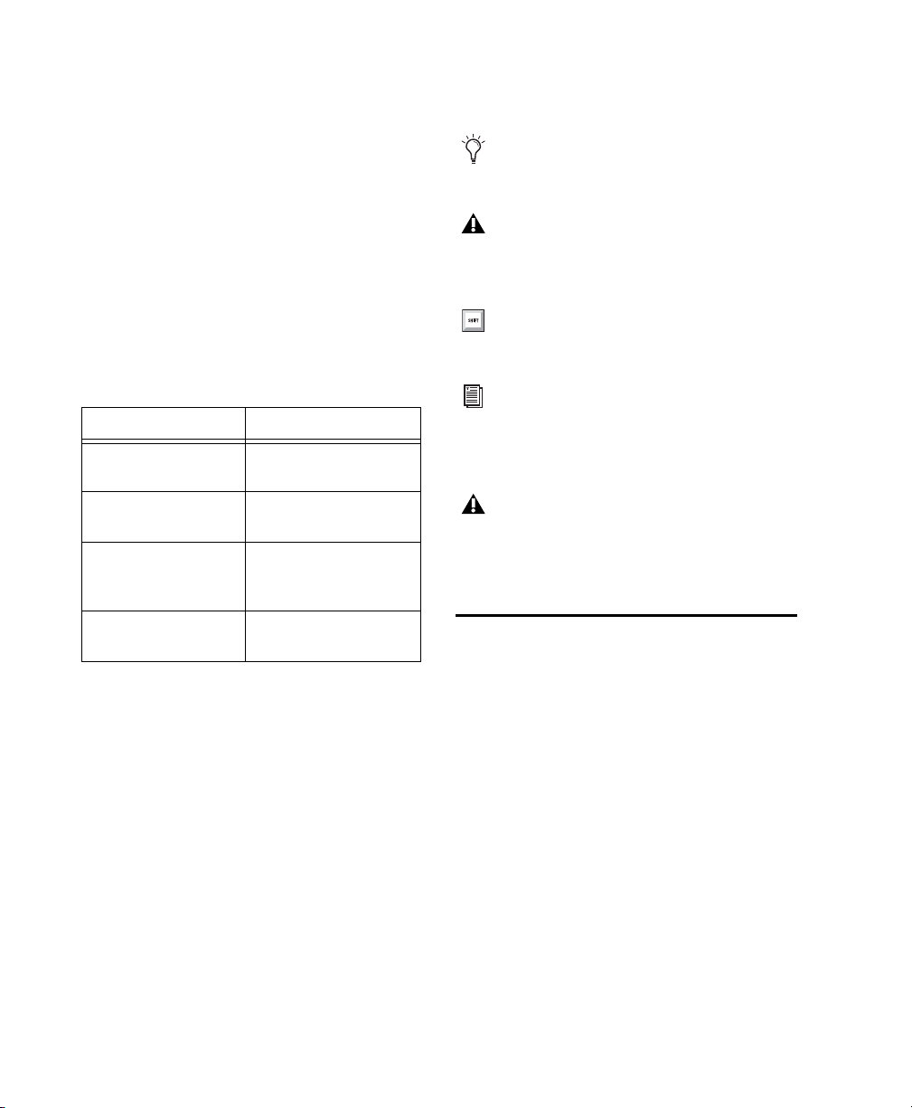
The following symbols are used to highlight
important information:
User Tips are helpful hints for getting the
most from your Pro Tools system.
Important Notices include information that
could affect your Pro Tools session data or
the performance of your Pro Tools system.
Conventions Used in These Guides
The Pro Tools guides use the following conventions to indicate menu choices, keyboard commands, and mouse commands:
:
Convention Action
File > Save Choose Save from the
File menu
Control+N Hold down the Control
Control-click Hold down the Control
Right-click Click with the right
The names of Commands, Options, and Settings
that appear on-screen are in a different font.
key and press the N key
key and click the mouse
button
mouse button
Shortcuts show you useful keyboard or
mouse shortcuts.
Cross References point to related sections in
this guide and other Pro Tools guides.
Pro Tools M-Powered
References to Pro Tools LE in this guide are
usually interchangeable with Pro Tools
M-Powered, except as noted in the
Pro Tools M-Powered User Guide.
System Requirements and Compatibility Information
Avid can only assure compatibility and provide
support for hardware and software it has tested
and approved.
For complete system requirements and a list of
qualified computers, operating systems, hard
drives, and third-party devices, visit:
www.avid.com/compatibility
Pro Tools Reference Guide4
Page 21

About www.avid.com
The Avid website (www.avid.com) is your best
online source for information to help you get
the most out of your Pro Tools system. The following are just a few of the services and features
available.
Product Registration Register your purchase
online.
Support and Downloads Contact Avid Customer
Success (technical support); download software
updates and the latest online manuals; browse
the Compatibility documents for system requirements; search the online Knowledge Base
or join the worldwide Pro Tools community on
the User Conference.
Training and Education Study on your own using
courses available online or find out how you can
learn in a classroom setting at a certified
Pro Tools training center.
Products and Developers Learn about Avid
products; download demo software or learn
about our Development Partners and their plugins, applications, and hardware.
News and Events Get the latest news from Avid
or sign up for a Pro Tools demo.
Chapter 1: Welcome to Pro Tools 5
Page 22

Pro Tools Reference Guide6
Page 23

Chapter 2: Pro Tools Concepts
This chapter explains some of the principles and
concepts that form the foundation of Pro Tools
operation and functionality.
Hard Disk Audio Recording
Hard disk recording is a nonlinear (or random access) medium—you can go immediately to any
spot in a recording without having to rewind or
fast forward.
This differs from tape-based recording, which is
a linear medium—where you need to rewind or
fast forward to hear a particular spot in a recording. To rearrange or repeat material in a linear
system, you need to re-record it, or cut and
splice it.
Nonlinear systems have several advantages. You
can easily rearrange or repeat parts of a recording by making the hard disk read parts of the recording in a different order and/or multiple
times. In addition, this re-arrangement is nonde-
structive, meaning that the original recorded material is not altered.
Pro Tools Nonlinear Editing
Pro Tools is a nonlinear recording editing system that lets you rearrange and mix recorded
material nondestructively. Nonlinear editing
simply means that you can cut, copy, paste,
move, delete, trim, and otherwise rearrange any
audio, MIDI, or video in the Pro Tools Edit window.
Nonlinear editing provides significant advantages over dubbing (re-recording), and cutting
and splicing magnetic tape. It gives you the
greatest possible flexibility for editing and arranging, and it is all nondestructive and “undoable.” Additionally, with nonlinear editing in
Pro Tools, you will never introduce any degradation of audio fidelity as you would with tape.
Chapter 2: Pro Tools Concepts 7
Page 24
The Digidesign Audio Engine
The Digidesign Audio Engine (DAE) is a realtime operating system for digital audio recording, playback, and processing. When you install
Pro Tools, DAE is automatically installed on
your system.
In the same way that a computer’s operating system provides the foundation for programs that
run on the computer, DAE provides the foundation for much of the hard disk recording, digital
signal processing, and mix automation required
by Pro Tools and other products from Avid and
its Development Partners.
The DAE Playback Buffer Size determines the
amount of memory DAE allocates to manage
disk buffers. The DAE Playback Buffer Size can
be changed in the Playback Engine.
For information on configuring the DAE
Playback Buffer Size, see “DAE Playback
Buffer Size” on page 56.
Pro Tools LE uses host (CPU) processing to provide audio track recording, playback, mixing,
and effects processing. Both Pro Tools LE and
Pro Tools HD use host processing to run RTAS
(Real-Time AudioSuite) plug-ins for effects processing. Performance is determined by your system and its Playback Engine settings.
The Playback Engine lets you set a hardware
buffer size and allocate a percentage of CPU
resources for these tasks.
®
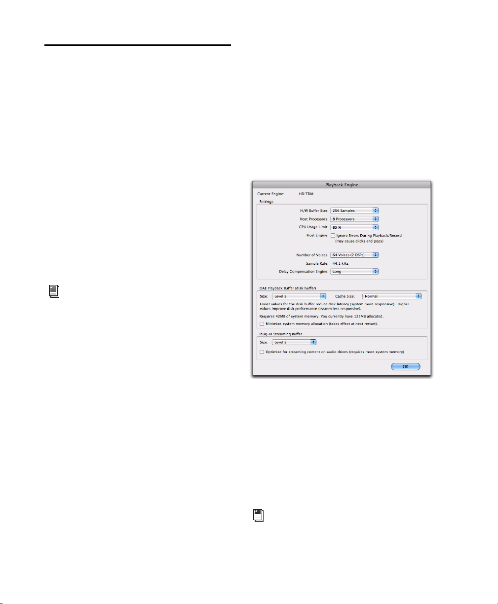
Playback Engine
Pro Tools lets you adjust the performance of
your system by changing system settings that
affect its capacity for processing, playback, and
recording. These system settings are available
in the Playback Engine (Setup > Playback Engine).
Pro Tools takes advantage of your computer’s
host processor for certain tasks and optional
host-based DSP processing.
Pro Tools Reference Guide8
Playback Engine for Pro Tools|HD system
On Pro Tools|HD systems, you can select the
number of voices and voiceable tracks for your
system and its sessions. Voice count choices are
based on how much DSP processing you want to
allocate for voicing.
On Pro Tools|HD systems, the Playback Engine
is also where you assign dedicated resources for
Delay Compensation.
For more information, see “Configuring
Pro Tools System Settings” on page 50. See
also “System Resources” on page 20.
Page 25
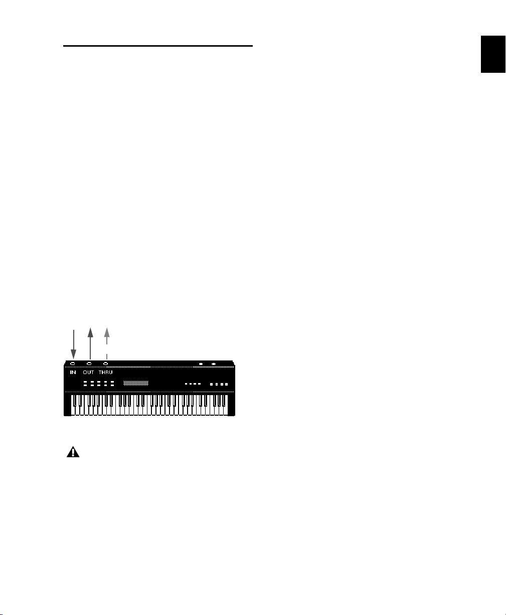
MIDI
passes input
MIDI (Musical Instrument Digital Interface) is a
communication protocol for musical instruments. This industry standard enables connections between a variety of devices from different
manufacturers. Examples of MIDI-compatible
equipment include synthesizers, sound modules, drum machines, MIDI patch bays, effects
processors, MIDI interfaces, MIDI control surfaces, and MIDI sequencers.
MIDI devices are equipped with 5-pin DIN connec tors, label ed as ei ther I N, OUT , or THR U. The
MIDI OUT port transmits messages. The MIDI
IN port receives messages. The MIDI THRU outputs whatever is received from the IN port. MIDI
devices are connected with MIDI cables that are
available at most music stores.
USB and FireWire-compatible MIDI devices send
and receive MIDI messages to and from the
computer over USB or FireWire.
strument sound. For example, bass on
channel 1, piano on channel 2, and drums on
channel 10. Similar to a multitrack tape recorder, a MIDI sequencer can record complex arrangements—even using only a single multitimbral keyboard.
MIDI Terms
The following are some basic MIDI terms:
MIDI Instrument A hardware MIDI device or
software instrument (such as an instrument
plug-in).
MIDI Interface Hardware that lets computers
connect to and communicate with MIDI devices
(such as the M-Audio MIDISPORT).
MIDI Device Any physical MIDI keyboard, sound
module, effects device, or other equipment that
can send or receive MIDI information.
MIDI Controller Any MIDI device that transmits
MIDI performance data. These include MIDI
keyboards, MIDI guitar controllers, MIDI wind
controllers, and others. Controllers transmit
MIDI from their MIDI OUT ports.
MIDI signal flow
Not all devices will have all three MIDI
ports (IN, OUT, and THRU).
The MIDI protocol provides 16 channels of
MIDI per port. A single MIDI cable can transmit
a separate set of messages for each of the 16
channels. These 16 channels can correspond to
separate MIDI devices or to multiple channels
within a single device (if the device is multitim-
bral). Each channel can control a different in-
MIDI Control Surface Any device (such as Command|8), which uses a MIDI connection to send
control messages to a software program, but is
not generally used to record MIDI information.
Multitimbral The ability of one MIDI device to
play several different instrument sounds (such
as piano, bass, and drums) simultaneously on
separate MIDI channels. This makes it possible
for a single multitimbral MIDI instrument to
play back entire arrangements.
Chapter 2: Pro Tools Concepts 9
Page 26

MIDI Port A physical MIDI port on a MIDI interface or a virtual MIDI port created in software.
There are separate ports for MIDI In and Out.
Physical MIDI ports connect to external MIDI
devices using MIDI cables. Virtual MIDI ports
connect software plug-ins and applications (see
also “Virtual MIDI Nodes”).
MIDI Channel Up to 16 channels of MIDI performance data can be transmitted on a single MIDI
cable. The channel number separates the different messages so your sound sources can receive
the correct messages.
Program Change Event A MIDI command that
tells a sound source which of its sounds (or
sound patches) to use. The MIDI protocol lets
you choose from a range of 128 patches.
Bank Select Message Many devices have more
than 128 patches, which are arranged in banks.
The Bank Select Message is a MIDI command
that specifies the bank of patches from which to
choose.
Local Control A controller setting found on most
MIDI keyboards that lets them play their own
sound source. Disabling “local control” ensures
that a device’s internal sound source is only
played by external MIDI messages (such as those
sent from Pro Tools when MIDI in Pro Tools is
routed to the MIDI keyboard). When using
Pro Tools, “local control” should usually be disabled (for example, when using MIDI Thru).
When “local control” is off, your keyboard still
transmits data to its MIDI OUT port.
Continuous Controller Events MIDI instructions
that allow real-time changes to notes that are
currently sounding. These include pitch bend,
modulation, volume, pan, and many others.
Virtual MIDI Nodes When using MIDI with instrument plug-ins in Pro Tools, virtual MIDI
nodes are created. These nodes act like MIDI
ports and provide software MIDI connections
between Pro Tools and other MIDI software,
such as instrument plug-ins. For example, when
you insert Propellerhead’s Reason as a ReWire
client on a track, the various MIDI inputs to
Reason become available to Pro Tools MIDI and
Instrument track MIDI outputs.
Common MIDI Misconceptions
MIDI is not audio, and by itself makes no sound.
MIDI is control information only. It is like the
piano roll for a player piano; it provides control
information for what note to play when, for
how long, at what volume, and with what
sound (instrument). For example, when you
strike a key on a MIDI keyboard, it sends a message to a MIDI instrument to play that particular
note at that particular velocity using the selected sound (instrument). This could be its internal tone generator (like a synthesizer or sampler), another external MIDI instrument, or an
instrument plug-in within Pro Tools. In order to
play and hear a MIDI recording, you must have
a MIDI instrument. Audio from an external
MIDI instrument can be sent to an external
mixer or monitored through your Pro Tools audio interface (using either an Instrument track
or Auxiliary track).
If you are using an external MIDI instrument, it
must be connected to MIDI ports that are recognized by your computer. These ports can be on a
Pro Tools interface that has MIDI ports (such as
an Mbox
as an M-Audio MIDISPORT).
®
2) or some other MIDI interface (such
System Exclusive Data MIDI data commonly
used for sending and retrieving patch parameter
information for storage purposes.
Pro Tools Reference Guide10
Page 27
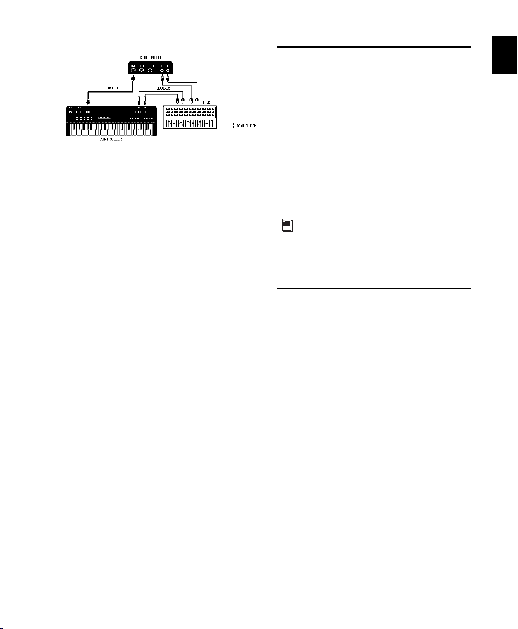
Signal paths for external MIDI instruments
To actually hear an external MIDI instrument,
you need to connect its audio outputs to a mixing console or connect it to one of the audio inputs of your Pro Tools audio interface.
Synchronization
When you are working with multiple timebased systems, such as Pro Tools and an external
deck, you want both systems to be synchronized. Synchronization is where one system outputs time code or MIDI Beat Clock and another
device synchronizes to or follows that time code
or MIDI Beat Clock so that they work together
according to the same clock source. Pro Tools
can be synchronized to other devices (or other
devices can be synchronized to Pro Tools) using
SMPTE/EBU time code or MIDI Time Code.
Just as each Pro Tools system has unique hardware features, each MIDI device has its own features (and limitations) as to the number of
voices and instruments it can play at one time.
Refer to the device’s documentation for information on its capabilities.
MIDI In Pro Tools
Pro Tools provides powerful MIDI sequencing
capabilities. You can record, enter, edit, and
play back MIDI data on Pro Tools Instrument
and MIDI tracks. These actions can be done in
the Edit window, the MIDI Editor window, the
Score Editor window, and the MIDI Event List.
MIDI data in Pro Tools can be anything from
MIDI note data (note number, on/off, velocity)
to System Exclusive (Sysex) messages. MIDI data
can be recorded or played back from both external MIDI devices with a MIDI interface (like the
M-Audio MIDISPORT or Mbox 2) and other
MIDI software (such as instrument plug-ins and
ReWire client applications).
For more information on different
SMPTE/EBU formats, and other concepts
related to time code, refer to the Pro Tools
Sync & Surround Concepts Guide.
Surround Sound
Surround sound simply means having one or
more speakers with discrete audio signals (channels) placed behind the listener in addition to
the typical stereo pair.
There are multiple types of surround formats in
use (from three-channel LCR to 7.1, which has
eight channels).
The most common surround format is 5.1,
which refers to having 5 speakers and a subwoofer (the “.1”). 5.1 is used in movie theaters
and home entertainment systems. Additionally,
most DVDs are mixed to 5.1. The standard
speaker placement for 5.1 for surround monitoring is stereo left and right speakers, and an additional center speaker in front, two more stereo
left and right speakers in the rear, and the subwoofer on the side.
Chapter 2: Pro Tools Concepts 11
Page 28
Pro Tools HD and Pro Tools LE with the Com-
Pro Tools HD
Pro Tools M-Powered
Pro Tools LE
plete Production Toolkit option support mixing
in surround formats. In Pro Tools, each surround format is considered to be a greater-than-
stereo multichannel format.
For information on fundamental surround
concepts, see the Pro Tools Sync & Surround
Concepts Guide.
There are different session file icons for each
type of Pro Tools system software.
Session file icons
Pro Tools Sessions
When you start a project in Pro Tools, you create
a session. Some basic elements of sessions are explained in this section.
Session File
A session file is the document that Pro Tools creates when you choose File > New Session and
configure a new session. Pro Tools can open
only one session file at a time. The session file is
named with a .ptf (Pro Tools file) extension. Session files contain maps of all elements associated with a project, including audio files, MIDI
data, and all your edit and mix information. It is
important to realize that a Pro Tools session file
does not contain any media files (audio or
video). Instead, it references audio, video, MIDI,
and other files. You can make changes to a session and save those changes in a new session
file. This lets you create multiple versions of a
session or back up your editing and mixing
work.
Although there are different session file icons,
session files may be opened by the other types of
Pro Tools system software (with certain restrictions). See “Opening a Session” on page 138.
When a session is transferred to a different
Pro Tools system, its session file icon
changes to the icon type of the destination
system.
Tracks
Pro Tools tracks are where audio, MIDI, video,
and automation data are recorded and edited.
Pro Tools tracks also provide audio channels for
routing internal busses, and physical inputs and
outputs for audio and MIDI.
Pro Tools Reference Guide12
Page 29
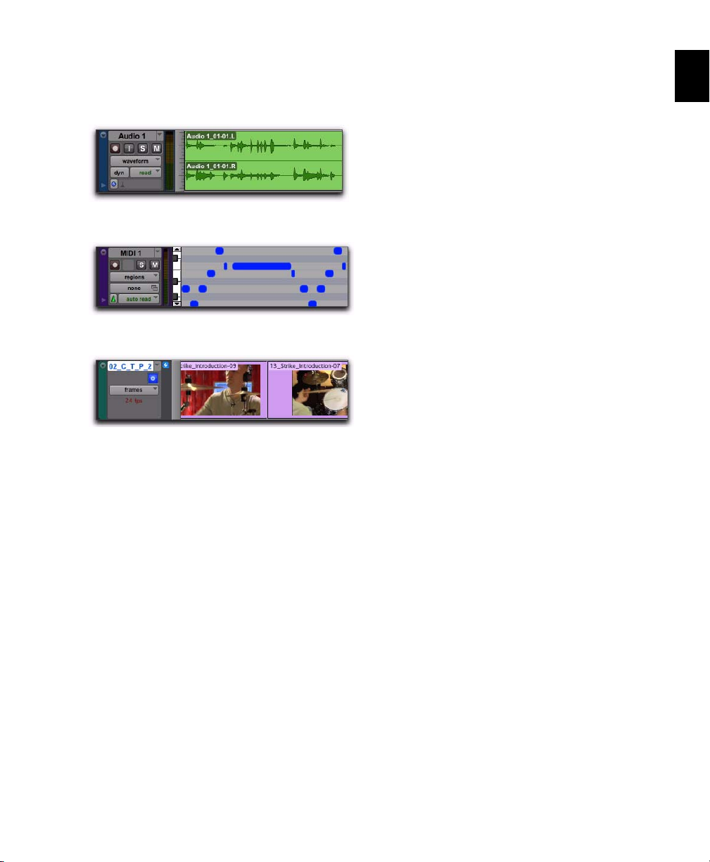
Pro Tools provides multiple types of tracks:
audio, Auxiliary Input, Master Fader, VCA Master, MIDI, Instrument, and video.
Video tracks support QuickTime movies (all
Pro Tools systems) and VC-1 video files (Windows Vista only). Additionally, Avid video is
supported on Pro Tools HD or Pro Tools LE with
DV Toolkit 2 software with an Avid video peripheral. An individual video track can play back
only one type of video at a time.
Audio track in the Edit window (stereo track shown)
MIDI track in the Edit window
Video track in Frames view
Audio, MIDI, Instrument, and video track data
can be edited into regions or repeated in different locations to create loops, re-arrange sections
or entire songs, or to assemble tracks using material from multiple takes.
Auxiliary Input tracks can route internal audio
busses or physical inputs to internal busses or
physical outputs. Auxiliary Inputs are typically
used for audio effects busses, audio throughput
(monitoring), and submixing.
Master Fader tracks provide controls for physical
audio output channels, including the volume
level of your mix, panning, and plug-in inserts.
Audio, Auxiliary Input, Master Fader, and Instrument tracks can be mono, stereo, or multichannel (Pro Tools HD and Pro Tools LE with
the Complete Production Toolkit option only).
When creating a new track, select from the list
of channel formats supported by your system.
Voices
In Pro Tools, voices are unique, discrete audio
streams that can be routed to and from
Pro Tools audio tracks physical audio outputs
and inputs on your Pro Tools audio interfaces.
The audio paths to and from Pro Tools software
routed to Pro Tools hardware use voices. If you
exceed the number of available voices in your
system, you have effectively exceeded the available number of audio paths.
Typically, each audio channel for each track in
your Pro Tools session uses a single voice. So, for
a mono audio track, a single voice is used; for a
stereo audio track, two voices are used. When
using Punch Recording, two voices are needed
for every single audio channel (one for playback
and one for recording on punch in and out). In
some situations, with Pro Tools|HD systems,
more than one voice may be necessary for a single channel (such as when using host processing
on a TDM bus).
VCA Master tracks (Pro Tools HD only) provide
control of tracks in a Mix Group that has been
assigned to the VCA Master.
Chapter 2: Pro Tools Concepts 13
Page 30
Voices can be allocated dynamically (with all
Pro Tools systems, any available voices are automatically assigned as they are needed) or explic-
itly (with Pro Tools HD only, you can explicitly
assign audio channels to specific available
voices to ensure that audio on that channel is always voiced).
Audio files for each session are stored in a folder
named “Audio Files.” Audio files are listed in the
Pro Tools Region List and can appear in an audio track. A section of an audio file can be defined as a region. See “Regions” on page 15.
MIDI Files
On Pro Tools|HD systems, the number of available voices is dependent on the amount of dedicated DSP processing in your system (see
“Pro Tools|HD System Playback, Recording and
Voice Limits” on page 34).
On Pro Tools LE systems, the full number of
available voices for your system may be limited
by the host processing power of your computer
(see “Pro Tools LE System Capabilities” on
page 42).
For more information about voicing in
Pro Tools, see “Track Priority and Voice Assignment” on page 206.
Media Files
Pro Tools sessions create, import, export, and
reference media files. Media files are audio,
MIDI, and video files. Audio and video media
files are stored separately from the Pro Tools session file. MIDI data is stored in the session file.
Audio Files
When you record or enter MIDI into a Pro Tools
session, all MIDI data is stored in the Pro Tools
session file. You can import and export MIDI
files to and from Pro Tools sessions, but MIDI
recorded or otherwise created in a Pro Tools
session does not automatically create new MIDI
files.
Video Files
When you record or import video into a
Pro Tools session, all video data is stored as the
corresponding video file type (such as QuickTime). Video files can be created in (or copied
to) the Video Files folder in the session folder.
However, in most cases, Pro Tools references
video files that have been captured by another
application, such as Avid Media Composer.
When you record audio into a Pro Tools session,
audio files are created.
Audio file icons
Pro Tools Reference Guide14
Page 31

Regions
and MIDI. A region can also have associated automation data. In Pro Tools, regions are created
from audio files or MIDI data, and can be arranged in audio and MIDI track playlists. Regions can also be grouped (a region of regions)
and looped (repeated).
Audio region
MIDI region
Video region (Frames view)
Region group (Mixed audio and MIDI multitrack region
group)
A region is a segment of audio, MIDI, or video
data. A region could be a drum loop, a guitar riff,
a verse of a song, a recording take, a sound effect, some dialog, or an entire sound file. Regions are especially useful for arranging audio
Playlist
Playlist selector pop-up menu
A playlist is a sequence of regions arranged on an
audio, MIDI, or video track. Tracks have edit
playlists and automation playlists.
On audio tracks, an edit playlist tells the hard
disk which audio regions to play in what order.
For example, you can have separate audio regions for a song introduction, the first verse, the
first chorus, and so on. You can also use the
same audio region to access the same piece of
audio multiple times at different locations and
not use additional disk space. Different versions
of the same original audio can be used in different places and have different effects applied. On
MIDI and Instrument tracks, edit playlists can
store multiple MIDI sequences (or performances) on a track.
A playlist can be made up of a single region or
many separate regions. It can be made up of similar elements, such as regions from several different takes of a solo, or dissimilar elements, such
as several sound effects.
Chapter 2: Pro Tools Concepts 15
Page 32

You can create any number of alternate edit
playlists for a track. This lets you assemble different versions of performances or edits on a single
track and choose between them from the Playlists menu on the track.
Each audio, Auxiliary Input, Instrument, Master
Fader, and VCA track also has a single set of automation playlists. Automation playlists can include volume, pan, mute, and each automationenabled control for the insert and send assignments on that track.
MIDI controller data on Instrument and MIDI
tracks is always included as part of the track
playlist.
Channel
The term channel is used to describe several related components of a Pro Tools system. The
first example of channel refers to a physical input or output of your Pro Tools system. For example, a 96 I/O audio interface provides up to
16 channels of audio input and output to a
Pro Tools|HD system, while an Mbox 2 audio interface provides up to four inputs and two outputs.
The second use of the term channel refers to a
channel strip in the Pro Tools Mix window.
Each track in a Pro Tools session has a corresponding channel strip in the Mix window.
Audio and MIDI channel strips have similar
controls, but those controls have slightly different effects. For example, audio, Auxiliary Input,
and Instrument track channel strip faders control the output gain to the mix bus for that
channel, while MIDI channel strip faders send
MIDI volume data (MIDI controller 7) to the selected MIDI instrument.
The term ‘MIDI channel’ also describes a
separate aspect of MIDI operation. See
“MIDI” on page 9.
Pro Tools Reference Guide16
Page 33

Input from
stereo bus
path
Outputs to
stereo bus
path
Audio tracks
Inserts
Sends
Auxiliary
Input
Track
Signal Routing
Pro Tools provides software-based mixing and
signal routing controls for audio and MIDI.
These controls are located in the Mix window.
Some of these controls can also be accessed from
the Edit window.
A common audio signal routing task is to submix multiple tracks to a single channel strip
(such as an Auxiliary Input) for shared processing and level control. The following example
shows two audio tracks submixed to a stereo
Auxiliary Input.
Channel strip in the Mix window (audio track)
Submixing to an Auxiliary Input
Chapter 2: Pro Tools Concepts 17
Page 34

Signal Routing Options
Signal routing options include the following:
Track Input and Output (I/O) Controls The most
basic type of signal routing is track input and
output. A track needs to have an assigned input
path to record audio, and an assigned mapped
output path in order to be audible through a
hardware output. Signals can also be routed to
or from other tracks in Pro Tools (or hardware
inputs and outputs) using internal busses.
Auxiliary Input and Master Fader Tracks Auxiliary Inputs can be used as returns, submixers,
and bus masters. Master Fader tracks are used as
bus and output master level controls. Both Auxiliary Input and Master Fader tracks can have
plug-in and hardware inserts.
MIDI Tracks MIDI tracks are generally used for
routing MIDI from internal or external sources
to external MIDI devices. MIDI data can also be
routed to plug-ins on Auxiliary Inputs or Instrument tracks.
Instrument Tracks Instrument tracks are the primary way to route MIDI to an instrument plugin and then route the plug-in’s sound to outputs, sends and busses, or other inserts. Instrument tracks can also be used to send MIDI to
and monitor audio from external MIDI devices.
Sends Sends route audio from tracks to hardware outputs, or to internal busses that are in
turn routed to other tracks within Pro Tools.
MIDI, Master Fader, and VCA Master tracks do
not have sends.
Plug-In and Hardware Inserts Plug-In processing
occurs completely within the Pro Tools system.
Hardware inserts use audio interface inputs and
outputs for traditional insert routing to and
from external effects and other devices. MIDI
and VCA Master tracks do not have inserts.
Instrument Plug-Ins Instrument plug-ins are different from processing plug-ins in that they generate audio rather than process the audio signal
from a track’s audio input or from hard disk.
Instrument plug-ins are typically played by
MIDI.
Paths Paths are any routing option in Pro Tools,
including internal or external inputs, outputs,
busses, and inserts. Pro Tools lets you name
these paths, and these path names appear in the
Audio Input and Output Path selectors and
other menus. For more information, see
Chapter 6, “I/O Setup.”
Mixing Formats Sessions can include combinations of mono, stereo, and greater-than-stereo
multichannel format tracks, busses, inputs, outputs, and inserts. Greater-than-stereo multichannel formats are supported with
Pro Tools HD, and Pro Tools LE with the Complete Production Toolkit option only.
Grouping and VCA Tracks Tracks can be grouped
together for mixing so that their relative mix
settings are maintained when changing a mix
setting for any track in the group (for example,
changing the volume of one track affects the
volume of all the other tracks in the group).
VCA Master tracks (Pro Tools HD only) control
the relative mix settings for all tracks within the
selected group.
Pro Tools Reference Guide18
Page 35

Tick-Based and Sample-Based Time
Pro Tools lets you set any track timebase to
either sample-based or tick-based. You can also
set the Timeline to be viewed as tick-based or
sample-based.
Audio in Pro Tools is sample-based by default.
This means that if an audio region is located at a
particular sample location, it will not move
from that location if the tempo changes in the
session—though its Bar|Beat location will
change.
MIDI data in Pro Tools is tick-based by default.
This means that if a MIDI region is located at a
particular Bar|Beat location, it will not move
from that Bar|Beat location if the tempo changes
in the session—though its sample location will
change.
You can select whether a track is sample-based
or tick-based when it is created, or change timebases later.
Sample-Based Audio and MIDI
With a sample-based audio track, all regions in
the track have an absolute location on the Timeline. Regions stay fixed to the sample time, regardless of where tempo or meter changes occur
in a session.
If you make a MIDI track sample-based, all MIDI
events in the track have an absolute location on
the Timeline. MIDI events stay fixed to sample
time, regardless of any tempo or meter changes
in a session.
Tick-Based Audio and MIDI
Tick-based audio is fixed to a Bars|Beat location,
and moves relative to the sample Timeline when
tempo and meter changes occur. However, MIDI
events and tick-based audio respond differently
to tempo changes with respect to duration.
MIDI note events change length when tempo or
meter is adjusted, while audio regions do not
(unless Elastic Audio is enabled). When Elastic
Audio is not enabled on an audio track, meter
and tempo changes affect only the start point
(or sync point) for each audio region in a tickbased track. If Elastic Audio is enabled on an audio track, tempo changes apply Elastic Audio
processing, which changes the duration of the
audio region.
Elastic Audio
Elastic Audio provides real-time and non-realtime (rendered) Time Compression and Expansion (TCE) of audio. Tick-based Elastic Audio
tracks actually change the location of samples
according to changes in tempo. The audio
stretches or compresses to match changes in
tempo. Elastic Audio also provides high-quality
non-real-time region-based pitch shifting.
Pro Tools Elastic Audio uses exceptionally highquality transient detection algorithms, beat and
tempo analysis, and real-time or rendered TCE
processing algorithms. Elastic Audio lets you
quickly and easily tempo conform and beat
match audio to the session’s Tempo ruler. It also
provides an unprecedented degree of control
over transient detection and TCE processing on
an event-by-event basis.
Chapter 2: Pro Tools Concepts 19
Page 36

With Elastic Audio, Pro Tools analyzes entire audio files for transient “events.” For example, an
event can be a drum hit, a sung note, or chord
played by a guitar. These detected events can
then serve as control points for “warping” the
audio. Pro Tools can warp (TCE) audio events
automatically, such as when automatically conforming audio to the session tempo or quantizing audio events, or you can warp audio manually using the standard editing tools with the
audio track set to Warp view.
Elastic Audio is useful in several common workflows: working with loops, correcting performances, remixing, beat and pitch matching,
and sound design and special effects.
In order to free up needed DSP resources,
Pro Tools allows for certain items (such as tracks
and inserts) to be manually made inactive. Inactive elements are viewable, editable, and retained within the session. See “Active and
Inactive Items” on page 20.
All Pro Tools systems provide flexible voice
options for audio tracks, to help maximize use
of available voices in your system. For more information on voice management and options,
see “Voice Borrowing” on page 209.
Active and Inactive Items
Pro Tools lets you make certain items (such as
tracks and inserts) inactive, in order to free up
DSP resources and mixer connections.
System Resources
Track count, plug-in processing, signal path and
routing options, and voice availability are ultimately limited by the combined resources available from the host computer and from your
Pro Tools hardware.
Pro Tools provides several ways to manage and
conserve resources to maximize the performance of your system. As you begin working
with Pro Tools sessions and tracks, you can take
advantage of the following features to extend
the effectiveness of your available DSP and other
resources:
Pro Tools lets you adjust the performance of
your system by changing system settings that affect its capacity for processing, playback, and recording. See “Configuring Pro Tools System
Settings” on page 50.
Items in Pro Tools that can be made inactive
include the following:
• Audio, Auxiliary Input, Master Fader,
VCA Master, and Instrument tracks
• Track Inputs and Outputs
•Sends
• Side-chain inputs
•Plug-Ins
• Hardware inserts
• Paths (session-wide)
MIDI tracks cannot be made inactive.
Side-chain inputs support direct active and
inactive switching, but do not follow
switching all or all selected side-chain
inputs.
Pro Tools Reference Guide20
Page 37

In addition to manually setting Active and Inac-
Active Inactive plug-in
Inactive track
tive modes, Pro Tools automatically makes
items inactive if there are insufficient or unavailable resources.
When active, items are fully engaged and operational.
When inactive, items are silent and off, although
most associated controls can still be adjusted.
Different inactive items affect available system
resources in specific ways, as follows:
Plug-Ins When a plug-in is inactive on a track, its
DSP is made available for other plug-ins and processing. Plug-In assignments can be made inactive manually or automatically (see “Automatic
and Manual Inactive Mode” on page 22).
Paths and Path Assignments When a path or
path assignment is inactive, its mixer resources
are made available for other signal routing purposes in the session. Paths and assignments can
be made inactive manually or automatically (see
“Automatic and Manual Inactive Mode” on
page 22).
Display of Inactive Items
When items are inactive, their names appear in
italics, and their background becomes dark gray.
When a track is inactive, the entire channel strip
is grayed out.
Tracks When a track is made inactive, its voices
become available for another track. Inactive
mono tracks free up one voice; inactive stereo
and multichannel tracks free up one voice per
channel. Additionally, when an audio, Auxiliary
Input, Instrument, or Master Fader track is made
inactive, its plug-ins, inserts, sends, and I/O
assignments become inactive, and the associated DSP used is freed up for use elsewhere in the
session.
Active and inactive plug-ins, sends, and tracks
Chapter 2: Pro Tools Concepts 21
Page 38

Automatic and Manual Inactive Mode
Active and Inactive modes are powerful options
for session transfer and system resource management. Pro Tools provides automatic and manual
Inactive mode switching. You can manually
make items inactive (or active) to selectively
manage system resources while editing and mixing.
DigiBase
DigiBase is a database management tool for
Pro Tools. DigiBase expands upon basic
Pro Tools search and import capabilities by providing powerful tools to manage your data both
inside and outside of your sessions, on any hard
drive connected to the system.
Automatically Inactive Items
When opening a session, it is possible that not
all signal paths, plug-ins, or audio interfaces
used in the session will be available as defined
on the current system. When opening a session,
sufficient voices may also be unavailable if the
session was created on a different Pro Tools system type (for example, opening a session created
on a Pro Tools HD system on a Pro Tools LE system).
Whenever this occurs, the session will open as it
was last saved. All items that are unavailable, or
cannot be loaded due to insufficient resources,
are made inactive.
Manual Inactive Switching
You can manually apply Active or Inactive
modes to manage system resources. By making
an item inactive, its associated resources are
made available elsewhere in the session.
A database is a way of organizing data such that
it can easily be searched, sorted, managed, and
utilized. Your checkbook is an example of a database file. For every check you write, you enter
a new record. That record contains information
about the check, such as when you wrote it, to
whom you wrote it, and for what amount. This
information is written in specific columns, or
fields. Everything you need to know (the check’s
metadata) is there, even though the check itself
is not.
DigiBase browsers let you search, sort, and
mange these databases by volume or catalog
(DigiBase Pro only). You can use DigiBase
browsers not only to organize your Pro Tools
sessions and media files (audio, MIDI, and
video), but also to audition and import by drag
and drop.
For more information about DigiBase, see
“DigiBase” on page 247.
Pro Tools Reference Guide22
Page 39

Chapter 3: Keyboard and Right-Click Mouse Shortcuts
This chapter provides an overview of Pro Tools
mouse and keyboard shortcuts.
A PDF listing of all shortcuts is available in
Pro Tools. Choose Help > Shortcuts.
Right-Click Mouse Shortcuts
Pro Tools provides Right-click shortcuts for
choosing various Pro Tools commands and
menus with any Right-click capable mouse.
For a complete list of Right-click shortcuts,
see the Shortcuts Guide.
Global Key Commands
This section covers keyboard shortcuts that
apply to many functions in Pro Tools.
For a complete list of keyboard shortcuts,
see the Shortcuts Guide.
Track Functions
Pro Tools provides keyboard shortcuts for the
following track functions:
• Changing Automation mode
• Enabling playlists
•Adding plug-ins
• Record enabling, soloing, and muting
tracks
• Record safing and solo safing tracks
• Assigning inputs, outputs, and sends
• Toggling volume/peak/delay display
• Clearing meters
• Changing track heights
Command Windows Mac
Apply action to all
channel strips/tracks
Apply action to
selected channel
strips/tracks
Alt+
action
Alt+
Shift+
action
Option+
action
Option+
Shift+
action
Chapter 3: Keyboard and Right-Click Mouse Shortcuts 23
Page 40

List and Parameter Selection
Region List
Keyboard Focus
Group List
Keyboard Focus
Commands Keyboard Focus
(Edit window)
There are three types of Keyboard Focus:
Pro Tools provides keyboard shortcuts for the
following items:
• Selection of tracks in Track List
• Enabling of groups in Group List
• Automation Enable window parameters
• Setting Memory Location parameters
Command Windows Mac
Toggle item and set
all others to same
new state
Toggle item and set
all others to opposite
state
Alt-click item Option-click
item
Control-click
item
Commandclick item
Controls and Editing Tools
Pro Tools provides keyboard shortcuts for moving plug-in controls, faders and sliders, the
Scrubber, and automation data.
Command Windows Mac
Fine adjustment
of sliders,
knobs, and
breakpoints
Hold Control
while clicking the item
Hold Command
while clicking
the item
Commands Keyboard Focus When selected in
the Tracks pane in the Edit window or in the
Notes pane of any MIDI Editor window, this
provides a wide range of single key shortcuts
from the computer keyboard for editing and
playing. The frontmost Edit or MIDI Editor window always receives Commands Keyboard Focus
when it is enabled.
With Commands Keyboard Focus disabled, you
can still access any of its key shortcuts by pressing the Start key (Windows) or Control (Mac)
along with the key.
For a complete list of Commands Keyboard
Focus shortcuts, see the Shortcuts Guide.
Region List Keyboard Focus When selected, audio regions, MIDI regions, and region groups
can be located and selected in the Region List by
typing the first few letters of the region’s name.
Group List Keyboard Focus When selected, Mix
and Edit Groups can be enabled or disabled by
typing the Group ID letter (in either the Mix or
Edit window).
Keyboard Focus
The Keyboard Focus in Pro Tools determines
how the alpha keys function. Depending on
which Keyboard Focus is enabled, you can use
the keys on your computer (alpha) keyboard to
select regions in the Region List, enable or disable groups, or perform an edit or play command.
You can only enable one of the three Keyboard
Focus modes at a time. Enabling a Keyboard Focus will disable the one previously enabled.
Pro Tools Reference Guide24
Keyboard Focus buttons
Page 41

To set the Keyboard Focus, do one of the following:
Click the a–z button for the focus you want to
enable.
– or –
While pressing Control+Alt (Windows) or
Command+Option (Mac), press one of the following keys: 1 (Commands), 2 (Region List), or
3 (Group List).
To enable Toolbar focus for the MIDI Editor pane,
do one of the following:
Click the Toolbar right above the MIDI Editor
pane.
– or –
Press Control+Alt+5 (Windows) or
Command+Option+5 (Mac).
Although multiple plug-in windows can have
a keyboard focus enabled, only the frontmost window receives any keyboard input.
Toolbar Focus
In the Edit window, the MIDI Editor pane can be
displayed in addition to the Tracks pane (View >
Other Displays > MIDI Editor). When the MIDI Editor pane is displayed, there are two separate
Toolbars and Timelines in the Edit window: one
for the Tracks pane and one for the MIDI Editor
pane. Only one Toolbar and Timeline can be focused for Menu and Toolbar commands (including the corresponding keyboard shortcuts) at a
time. The focused Toolbar displays a yellow outline.
If Keyboard Focus for the Edit window is enabled, it follows the selected Toolbar focus.
To enable Toolbar focus for the Tracks pane, do
one of the following:
Click the Toolbar at the top of the Edit
window.
– or –
Numeric Keypad Modes
The Operation preference for Numeric Keypad
mode determines how the numeric keypad
functions for Transport.
There are two Shuttle Lock modes (Classic and
Transport), and one Shuttle mode.
No matter which Numeric Keypad mode is selected, you can always use the numeric keypad
to select and enter values in the Event Edit Area,
Edit Selection indicators, Main and Sub Counters, and Transport fields.
To set the Numeric Keypad Mode:
1 Choose Setup > Preferences and click the Oper-
ation tab.
2 In the Transport section, select a Numeric Key-
pad mode (Classic, Transport, or Shuttle).
3 Click OK.
For more information on each mode, see
“Numeric Keypad Mode” on page 107.
Press Control+Alt+4 (Windows) or
Command+Option+4 (Mac).
Chapter 3: Keyboard and Right-Click Mouse Shortcuts 25
Page 42

Shuttle Lock Modes
Transport Mode
With either Shuttle Lock mode (Classic or Transport) you can use the numeric keypad to shuttle
forward or backwards at specific speeds.
• 5 is normal speed.
• 6–9 provide increasingly faster fast-forward
speeds.
• 1–4 provide progressively faster rewind
speeds (4 is the slowest rewind Shuttle Lock
speed, 1 is the fastest).
• Press 0 to stop Shuttle Lock, then press the
number to resume Shuttle Lock speed.
• Press Escape or Spacebar to exit Shuttle
Lock mode.
Custom Shuttle Lock Speed
(Pro Tools HD and Pro Tools LE with Complete
Production Toolkit or DV Toolkit 2 Only)
The highest fast-forward Shuttle Lock speed
(key 9) can be customized.
For information, see “Custom Shuttle Lock
Speed” on page 494.
Classic Mode
This mode emulates the way Pro Tools worked
in versions lower than 5.0. With the Numeric
Keypad mode set to Classic, you can:
• Play up to two tracks of audio in Shuttle
Lock mode. Press the Start key (Windows)
or Control (Mac), followed by 1–9 for different play speeds.
• Press Plus or Minus to reverse direction.
• Press 0 to stop Shuttle Lock, then press the
number to resume Shuttle Lock speed.
• Press Escape or Spacebar to exit Shuttle
Lock mode.
• Recall Memory Locations by typing the
Memory Location, followed by a Period (.).
This mode allows you to set a number of record
and play functions, and also operate the Transport from the numeric keypad.
:
Function Key
Click on/off 7
Countoff on/off 8
MIDI Merge/Replace mode 9
Loop Playback mode on/off 4
Loop Record mode on/off 5
QuickPunch mode on/off 6
Rewind 1
Fast Forward 2
Record enable 3
Play/Stop 0
With the Numeric Keypad mode set to Transport,
you can also:
• Play up to two tracks of audio in Shuttle
Lock mode. Press the Start key (Windows)
or Control (Mac), followed by 1–9 for different play speeds.
• Press Plus or Minus to reverse direction.
• Press 0 to stop Shuttle Lock, then press the
number to resume Shuttle Lock speed.
• Press Escape or Spacebar to exit Shuttle
Lock mode.
• Recall Memory Locations by typing Period
(.), the Memory Location number, and Period (.) again.
Pro Tools Reference Guide26
Page 43

Shuttle Mode
(Pro Tools HD Only)
Pro Tools offers another form of shuttling, different from that of the two Shuttle Lock modes.
With the Numeric Keypad mode set to Shuttle,
playback of the current Edit selection is triggered by pressing and holding the keys on the
numeric keypad—playback stops once the keys
are released. Various playback speeds are available in both forward and reverse. In this mode,
pre- and post-roll are ignored.
:
Playback Speeds Key
1x Forward 6
1x Rewind 4
4x Forward 9
4x Rewind 7
1/4x Forward 3
1/4x Rewind 1
1/2x Forward 5+6
1/2x Rewind 5+4
2x Forward 8+9
2x Rewind 8+7
1/16x Forward 2+3
1/16x Rewind 2+1
Loop Selection (1x) 0
With the Numeric Keypad mode set to Shuttle,
you can also:
• Recall Memory Locations by typing Period (.),
the Memory Location number, and Period (.)
again.
Shuttle Lock modes are not available when
the Numeric Keypad mode is set to Shuttle.
Chapter 3: Keyboard and Right-Click Mouse Shortcuts 27
Page 44

Pro Tools Reference Guide28
Page 45

Part II: System Configuration
29
Page 46

30
Page 47

Chapter 4: Pro Tools Systems
There are three types of Pro Tools systems:
Pro Tools|HD These systems include
Pro Tools HD software for Pro Tools|HD system
hardware.
Pro Tools LE These systems include Pro Tools LE
software for 003
Digi 002
Mbox
Mbox 2 Micro hardware.
®
®
2, Mbox 2 Pro, Mbox 2 Mini, or
™
, 003 Rack, 003 Rack+,
, Digi 002 Rack™, Eleven® Rack,
Pro Tools|HD Systems
Pro Tools|HD systems are available in the configurations shown on page 32. Each system requires at least one Pro Tools|HD audio interface
(sold separately). Pro Tools|HD systems can be
expanded by adding Pro Tools|HD cards to increase track count and the amount of plug-in
and mixer processing, and by adding additional
audio interfaces.
Pro Tools M-Powered These systems include
Pro Tools M-Powered software for qualified
M-Audio
®
interfaces.
References to Pro Tools LE in this guide are
usually interchangeable with Pro Tools
M-Powered, except as noted in the Pro Tools
M-Powered User Guide.
Pro Tools LE System Options
Pro Tools LE with Complete Production
Toolk it Pro Tools LE systems that have been
upgraded with the Complete Production Toolkit
software option.
Pro Tools LE with DV Toolkit 2 Pro Tools LE
systems that have been upgraded with the
DV Toolkit
Pro Tools LE or M-Powered with Music Production
Toolk it 2 Pro Tools LE or M-Powered systems
that have been upgraded with the Music
Production Toolkit 2 software option.
™
2 software option.
Pro Tools system performance depends on
factors such as computer processor speed,
amount of system memory, and hard drive
performance. Visit the Avid website
(www.avid.com) for the latest system
requirements and compatibility information.
Chapter 4: Pro Tools Systems 31
Page 48

Pro Tools|HD Systems
Pro Tools|HD 1
Includes:
• Accel Core (for PCIe) card or
HD Core
• Pro Tools HD software
Pro Tools|HD 2 Accel
Includes:
• Accel Core (for PCIe) card or
HD Core (for PCI) card
• HD Accel card
• Pro Tools HD software
™
(for PCI) card
Supported Pro Tools|HD Audio
Interfaces
The following audio interfaces are compatible
with Pro Tools|HD systems:
•HD I/O
•HD OMNI
• HD MADI
•192 I/O
•192 Digital I/O
•96 I/O
•96i I/O
™
™
™
™
Pro Tools|HD systems require at least one
HD I/O, HD OMNI, HD MADI, 192 I/O,
192 Digital I/O, 96 I/O, or 96i I/O.
Pro Tools|HD 3 Accel
Includes:
• Accel Core (for PCIe) card or
HD Core (for PCI) card
• Two HD Accel cards
• Pro Tools HD software
Pro Tools|HD 2
Includes:
• HD Core card
™
•HD Process
card
• Pro Tools HD software
Pro Tools|HD 3
Includes:
• HD Core card
• Two HD Process cards
• Pro Tools HD software
Pro Tools|HD PCI cards require a PCI to
PCIe expansion chassis. For more information, see the Expanded Systems Guide.
Supported Legacy Pro Tools MIX Audio
Interfaces
The following “Legacy” Pro Tools|24 MIX™ audio interfaces are supported with Pro Tools|HD
systems:
•888|24I/O
•882|20I/O
• 1622 I/O
• 24-bit ADAT Bridge I/O
™
™
™
™
“Legacy” I/Os (such as 888|24 I/O) require
the use of at least one 192 I/O,
192 Digital I/O, or 96 I/O. Legacy I/O are
only supported with session sample rates of
44.1 kHz and 48 kHz.
Pro Tools Reference Guide32
Page 49

Expanded Pro Tools|HD Systems
You can expand your Pro Tools|HD system by
adding Pro Tools|HD cards to your computer, either directly in the computer or using an expansion chassis. Expanding your Pro Tools system
provides increased track counts, adds to the
amount of possible plug-in and mixer processing, and lets you connect additional audio interfaces. With support for up to 7 Pro Tools|HD
cards in a single system, a Pro Tools|HD system
can support up to 160 channels of simultaneous
input and output.
Maximum I/O Configuration
Pro Tools|HD supports up to a maximum combination of ten total of the following audio interfaces:
• HD OMNI (only one HD OMNI is supported in a single Pro Tools|HD system)
• HD I/O (up to ten HD I/O can be used simultaneously—requires five HD cards)
• HD MADI (up to three HD MADI can be
used simultaneously—requires six HD
cards)
• 192 I/O (up to ten 192 I/O can be used simultaneously—requires five HD cards)
• 192 Digital I/Os (up to ten 192 Digital I/O
can be used simultaneously—requires five
HD cards)
• 96 I/Os (up to ten 96 I/O can be used simultaneously—requires five HD cards)
• 96i I/Os (up to five 96i I/Os can be used simultaneously)
For more information, see the Expanded
Systems Guide
.
Chapter 4: Pro Tools Systems 33
Page 50

Pro Tools|HD System Playback, Recording and Voice Limits
The following table lists the audio playback, recording, and voiceable track limits of each type of
Pro Tools|HD system. Playback and recording voices refer to the number of unique simultaneous
playback and record tracks on your system. Total voiceable tracks refers to the maximum number of
audio tracks that can share the available voices on your system. (Mono tracks take up one voice. Stereo and multichannel tracks take up one voice per channel.) Voice limits are dependent on the session sample rate and the number of DSP chips dedicated to the system’s Playback Engine.
Pro Tools|HD systems can open sessions with up to 256 audio tracks, but any audio tracks beyond that
system’s voiceable track limit will be automatically set to Voice Off.
Table 5. Pro Tools|HD system audio playback, recording and voice limits
Playback and Recording
Core System Type Sample Rate (kHz)
Pro Tools|HD 1 44.1/48 96 (2 or 3 DSPs) 256
88.2/96 48 (2 or 3 DSPs) 256
176.4/192 18 (for PCIe) (3 DSPs)
Pro Tools|HD Accel 2,
Pro Tools|HD Accel 3
Pro Tools|HD 2,
Pro Tools|HD 3,
or any expanded
Pro Tools|HD system
44.1/48 192 (6 DSPs) 256
88.2/96 96 (6 DSPs) 256
176.4/192 36 (6 DSPs) 256
44.1/48 128 (4 DSPs) 256
88.2/96 64 (4 DSPs) 256
176.4/192 24 (4 DSPs) 256
Voices (Mono Tracks of
Simultaneous Playback
and Recording)
12 (for PCI) (2 DSPs)
Total Available
Voiceable Tracks
(Max.)
256
Pro Tools|HD systems provide up to 160 Auxiliary Input tracks and a total of 128 internal mix busses.
These systems also provide up to 10 inserts and 10 sends per track (depending on the DSP capacity of
your system). Pro Tools|HD systems also support up to 128 Instrument tracks, 256 MIDI tracks,
128 VCA Master tracks, 64 Master Fader tracks, and multiple video tracks.
Pro Tools Reference Guide34
Page 51

Pro Tools|HD Audio Interfaces
Table 6 lists the input and output capabilities of the various Pro Tools|HD audio interfaces for
Pro Tools|HD systems. Pro Tools|HD cards support a maximum of 32 channels of I/O each. To record
and play audio with Pro Tools HD, you must have at least one Pro Tools|HD audio interface connected to the Pro Tools|HD Core card in your system.
Table 6. Pro Tools|HD system audio interface channel capabilities
Interface Type
HD I/O 16 in/16 out 44.1, 48,
HD OMNI 8 in/8 out 44.1, 48,
HD MADI 64 in/64 out 44.1, 48,
192 I/O
(Pro Tools|HD Only)
192 Digital I/O
(Pro Tools|HD Only)
96 I/O
(Pro Tools|HD Only)
96i I/O
(Pro Tools|HD Only)
Number of I/O
Channels
8 in/8 out 44.1, 48,
8 in/8 out 44.1, 48,
8 in/8 out 44.1, 48,
16 in/2 out 44.1, 48,
Sample Rates
(kHz)
88.2, 96,
176.4, 192
88.2, 96,
176.4, 192
88.2, 96,
176.4, 192
88.2, 96,
176.4, 192
88.2, 96,
176.4, 192
88.2, 96
88.2, 96
A/D
Conversion
24-bit 24-bit 24-bit
24-bit 24-bit 24-bit
None None 24-bit
24-bit 24-bit 24-bit
None None 24-bit
24-bit 24-bit 24-bit
24-bit 24-bit 24-bit
D/A
Conversion
Digital I/O
888|24 I/O
(Pro Tools|HD Only)
882|20 I/O
(Pro Tools|HD Only)
1622 I/O
(Pro Tools|HD Only)
24-bit ADAT Bridge I/O
(Pro Tools|HD Only)
8 in/8 out 44.1, 48 24-bit 24-bit 24-bit
8 in/8 out 44.1, 48 20-bit 20-bit 24-bit
16 in/2 out 44.1, 48 20-bit 24-bit 24-bit
16 in/16 out 44.1, 48 None 24-bit 24-bit
Chapter 4: Pro Tools Systems 35
Page 52

HD OMNI Audio Interface
HD OMNI is a professional digital audio
interface designed for use with Pro Tools|HD
systems. HD OMNI provides a compact preamp,
monitoring, and I/O solution for music production and recording, and post production
studios.
HD OMNI Features
HD OMNI provides up to 8 discrete channels of
Pro Tools input and output, with 4-segment
LED meters for input or output (selectable).
Analog I/O
• 24-bit analog-to-digital (A/D) and digital-toanalog (D/A) converters, with support for
sample rates up to 192 kHz
• 2 high-quality Mic/DI preamps (Channels
1–2)
• 2 combined XLR and 1/4-inch TRS front panel
inputs for microphone and instrument level
input
• 2 XLR back panel microphone inputs
• 2 1/4-inch TRS Send and 2 1/4-inch TRS Return back panel jacks for hardware inserts on
channels 1 and 2
• 4 analog TRS line level back panel inputs
(Channels 1–4)
HD OMNI provides multiple analog input
connections, but only provides up to four
channels of simultaneous analog input for
Pro Tools.
• Soft Clip and Curv limiting circuits to protect
against clipping on analog input.
• 8 channels of analog back panel output using
a DB-25 breakout cable (sold separately) with
variable output gain
• 2 channels of analog back panel output using
TRS (Mirrors channels 1–2 or 7–8 on DB-25
connector)
• Front panel stereo 1/4” headphone jack
Digital I/O
• 8 channels of AES/EBU output (up to 192 kHz
Single Wire) using a DB-25 breakout cable
(sold separately)
• 2 channels of AES/EBU XLR input (up to
192 kHz Single Wire)
• 2 channels of S/PDIF RCA input and output
(up to 192 kHz)
• 8 channels of ADAT TOSLINK input and
output
• Support for ADAT S/MUX Optical for sample
rates of 88.2 kHz, 96 kHz, 176.4 kHz, and
192 kHz.
• Support for two channels of S/PDIF Optical
with sample rates of up to 96 kHz.
• Real-time sample rate conversion (SRC) on
Digital Inputs 1–2 of either AES/EBU, S/PDIF,
or Optical (S/PDIF)
SRC is not supported with ADAT S/MUX.
Monitoring
• An additional stereo “CUE” output path in
Pro Tools for headphone monitoring from the
front panel headphone jack
• Front panel Control Room (MAIN/ALT) and
Headphone monitoring volume control
• Flexible monitoring with fold-down from
all stereo and surround formats (up to 7.1
surround)
• Input mixer for low latency direct monitoring
of a variety of incoming signals (configured in
Pro Tools Hardware Setup)
Pro Tools Reference Guide36
Page 53

Synchronization
• Loop Sync input and output for connecting
additional Pro Tools|HD interfaces and
peripherals
• External Clock input and output for synchronizing HD OMNI with external Word Clock
devices.
For more information about HD OMNI, see
the HD OMNI Guide.
HD I/O Audio Interface
HD I/O is a multichannel digital audio interface
designed for use with Pro Tools|HD systems.
HD I/O features extremely high quality 24-bit
analog-to-digital (A/D) and digital-to-analog
(D/A) converters, and supports sample rates of
up to 192 kHz.
HD I/O comes in three standard configurations:
• 8 x 8 x 8 (8 analog in, 8 analog out, and
8 digital in and out)
• 16 x 16 analog in and out
• 16 x 16 digital in and out
You can also add or remove HD I/O Analog Expansion cards (ADC and DAC) and HD I/O Digital Expansion cards for custom configurations.
HD I/O Features
HD I/O provides up to 16 discrete channels of
Pro Tools input and output, with 4-segment
LED meters for input and output.
Analog I/O
• Up to sixteen channels of 24-bit D/A and A/D
converters for superior analog input and output at sample rates of 44.1 kHz, 48 kHz,
88.2 kHz, 96 kHz, 176.4 kHz, and 192 kHz
with Analog In and Analog Out HD I/O cards
• Soft Clip and Curv limiting circuits to protect
against clipping on analog input.
Digital I/O
• Up to sixteen channels of 24-bit digital I/O,
using AES/EBU, TDIF DB-25, or Optical at
sample rates of 44.1 kHz, 48 kHz, 88.2 kHz,
96 kHz, 176.4 kHz, and 192 kHz with a Digital
HD I/O card
• Real-time sample rate conversion on digital
inputs with a Digital I/O card (up to sixteen
channels of AES/EBU, Optical, or TDIF)
• Support for S/MUX Optical for sample rates of
88.2 kHz and higher
• Support for 2 channels of S/PDIF Optical
(enclosed) with sample rates of up to 96 kHz
• 2 channels of AES/EBU I/O (enclosed) with
support for sample rates up to 192 kHz
• 2 channels of 24-bit-capable S/PDIF I/O
(enclosed) with support for sample rates up to
192 kHz
Synchronization
• Loop Sync input and output for connecting
additional Pro Tools|HD interfaces and
peripherals
• External Clock input and output for synchronizing HD I/O with external Word Clock
devices
Expandability
• Optional addition of I/O cards to expand
analog or digital I/O capacity
• Simultaneous use of multiple Pro Tools|HD
audio interfaces to further expand system
input and output (for more information, see
the Expanded Systems Guide)
For more information about HD I/O, see the
HD I/O Guide.
Chapter 4: Pro Tools Systems 37
Page 54

HD MADI Digital Audio Interface
HD MADI is a 64-channel digital audio interface
designed for use with Pro Tools|HD systems.
HD MADI supports the Multichannel Audio
Digital Interface (MADI) format and sample
rates up to 192 kHz. HD MADI provides simplified connectivity between your Pro Tools|HD
system and MADI-compatible audio equipment,
such as routers, digital mixing consoles, and
converters.
HD MADI Features
• 2 MADI Optical and Coaxial inputs and 2
MADI Optical and Coaxial outputs for up
to 64 discrete channels of digital input and
output (32 channels per DigiLink Mini port)
• Supports sample rates of 44.1 kHz, 48 kHz,
88.2 kHz, 96 kHz, 176.4 kHz, and 192 kHz
• 24- or 16-bit resolution
• Sample Rate Conversion (SRC) on input or
output
• Front panel clock and SRC indicators
• Front panel signal present LEDs for input and
output
• BNC Word Clock I/O for synchronizing HD
MADI with external 1x Word Clock
• BNC Loop Sync I/O for synchronizing HD
MADI with additional Pro Tools|HD audio interfaces and peripherals (such as HD I/O,
HD OMNI, or SYNC HD)
• Dedicated BNC Word Clock input and XLR
AES/EBU input (clock input only) for external
MADI synchronization (when using SRC on
output)
• Clock support for the following formats: Internal, Loop Sync, Word Clock, AES/EBU, and
MADI
• Varispeed modes (supports both 64- and 56channel standards)
`
For more information about HD MADI, see
the HD MADI Guide.
192 I/O Audio Interface
192 I/O™ is a multichannel digital audio interface designed for use with Pro Tools|HD systems. 192 I/O features high quality 24-bit analog-to-digital (A/D) and digital-to-analog (D/A)
converters, and supports sample rates of up to
192 kHz.
You can also add or remove analog cards and
digital cards (ADC and DAC) for custom configurations.
192 I/O Features
• Supports sample rates up to 192 kHz.
• Supports both analog and digital connections,
including AES/EBU, S/PDIF, TDIF, and ADAT
Optical:
• Digital (Digital I/O Card): 8 channels, DB25 (AES/EBU and TDIF), or one pair of
Lightpipe (ADAT Optical) connectors. Expandable up to 16 of channels digital I/O
with the addition of the 192 Digital expansion card.
• Analog: 8 channels, DB-25 (balanced) connectors, inputs selectable between +4 dBu
or –10 dBV, outputs +4 dBu only. Expandable up to 16 analog inputs or 16 outputs
using an optional 192 AD or 192 DA expansion card, respectively.
• Digital (Enclosure): 2 channels, XLR
(AES/EBU) connectors; 2 channels RCA
(S/PDIF) connectors.
• Optical (Enclosure): 8 channels, one pair of
Lightpipe (ADAT Optical) connectors (switchable to 2 channels, S/PDIF).
• Loop Sync In and Out for connecting
Pro Tools|HD interfaces and peripherals
Pro Tools Reference Guide38
Page 55

• External Clock In and Out receive or send 1x
Word clock (configurable to 256x for Legacy
support, see “Optional Legacy I/O Audio Interfaces” on page 40).
For more information about the 192 I/O,
see the 192 I/O Guide.
96 I/O Audio Interface
96 I/O™ is a multichannel digital audio interface
designed for use with Pro Tools|HD systems.
96 I/O features high quality 24-bit analog-todigital (A/D) and digital-to-analog (D/A) converters, and supports sample rates up to 96 kHz.
192 Digital I/O Audio Interface
192 Digital I/O™ is a multichannel digital audio
interface designed for use with Pro Tools|HD
systems, and supports sample rates up to
192 kHz.
192 Digital I/O Features
• Supports sample rates up to 192 kHz.
• Supports digital connections, including
AES/EBU, S/PDIF, TDIF, and ADAT Optical:
• Digital (2 Digital I/O Cards): 16 channels,
DB-25 (AES/EBU and TDIF), or two pairs of
Lightpipe (ADAT Optical) connectors.
• Digital (Enclosure): 2 channels, XLR
(AES/EBU) connectors; 2 channels RCA
(S/PDIF) connectors.
• Optical (Enclosure): 8 channels, one pair of
Lightpipe (ADAT Optical) connectors (selectable to 2 channels, S/PDIF).
• Loop Sync In and Out for connecting
Pro Tools|HD interfaces and peripherals.
• External Clock In and Out receive or send 1x
Word clock (configurable to 256x for Legacy
support, see “Optional Legacy I/O Audio Interfaces” on page 40).
For more information about the 192
Digital I/O, see the 192 Digital I/O Guide.
96 I/O Features
• Supports sample rates up to 96 kHz.
• Supports analog and digital connections, including AES/EBU, S/PDIF, and ADAT optical:
• Analog: 8 channels, 1/4-inch TRS (balanced
or unbalanced) connectors, +4 dBu or
–10 dBV.
• Digital: 2 channels, XLR (AES/EBU) connectors; 2 channels, RCA (S/PDIF) connectors.
• Optical: 8 channels, one pair of Lightpipe
(ADAT Optical) connectors (switchable to 2
channels, S/PDIF).
• External Clock In and Out receive or send
1x Word clock (configurable to 256x for
Legacy support, see “Optional Legacy I/O
Audio Interfaces” on page 40).
For more information about the 96 I/O, see
the 96 I/O Guide.
96i I/O Audio Interface
96i I/O™ is a multichannel digital audio interface designed for use with Pro Tools|HD
systems. 96i I/O features high quality 24-bit
analog-to-digital (A/D) and digital-to-analog
(D/A) converters, and supports sample rates up
to 96 kHz.
Chapter 4: Pro Tools Systems 39
Page 56

96i I/O Features
• Supports sample rates up to 96 kHz.
• 16 discrete channels of input, and 2 channels
of output, with 4-segment LED meters on
each channel. Audio inputs and outputs include:
• 16 channels of 24-bit, 96-kHz capable analog input, with adjustable input sensitivity.
• 2 channels of 24-bit, 96-kHz capable analog
output, with selectable operating level.
• 2 channels of 24-bit, 96 kHz-capable digital
S/PDIF RCA input and output.
• Loop Sync In and Out for connecting
Pro Tools|HD interfaces and peripherals.
• External Clock In and Out receive or send 1x
Wor d clo ck.
For more information about the 96i I/O, see
the 96i I/O Guide.
Optional Legacy I/O Audio Interfaces
For additional input and output channels, older
Pro Tools|24 MIX
I/Os) can be connected to the 192 I/O,
192 Digital I/O, or 96 I/O (HD OMNI, HD I/O,
HD MADI, and 96i I/O do not support
Pro Tools|24 MIX audio interfaces). The following supported legacy interfaces can only be used
with 44.1 kHz or 48 kHz sessions:
888|24 I/O Audio Interface
• Analog: 8 channels, XLR (balanced or unbalanced) connectors, selectable between +4 dBu
or –10 dBV
• Digital: 8 channels, XLR (AES/EBU) connectors; 2 channels, RCA (S/PDIF) connectors
™
audio interfaces (or Legacy
882|20 I/O Audio Interface
• Analog: 8 channels, 1/4-inch TRS (balanced or
unbalanced) connectors, selectable between
+4 dBu and –10 dBV
• Digital: 2 channels, RCA (S/PDIF) connectors
1622 I/O Audio Interface
• Analog: 16 input channels and 2 output channels, 1/4-inch TRS (balanced or unbalanced)
connectors. Inputs are selectable from +4 dBu
to –10 dBV line levels and higher in 2 dB gain
steps; outputs are selectable between +4 dBu
or –10 dBV.
• Digital: 2 channels, RCA (S/PDIF) connectors.
24-bit ADAT Bridge I/O
• Optical: 16 channels, a pair of Lightpipe
(ADAT) connectors.
• Analog output: 2 channels, 1/4-inch TRS (balanced) connectors, selectable between +4 dBu
and –10 dBV.
• Digital: 2 channels, XLR (AES/EBU); 2 channels RCA (S/PDIF) connectors.
Additional Pro Tools|HD Hardware
Pro Tools HD also supports the following
Pro Tools|HD hardware options.
• Synchronization peripherals:
•SYNC HD
•SYNC I/O
• PRE™ (Eight-channel microphone preamp)
• MIDI I/O
• Worksurfaces and control surfaces:
• D-Command
• D-Control
•C|24
• Command|8
™
™
™
(10 x 10 USB MIDI interface)
®
™
™
®
Pro Tools Reference Guide40
Page 57

Pro Tools LE Systems
Pro Tools LE-based systems are available in the
following configurations:
003
Eleven Rack
An Eleven Rack system includes:
• Pro Tools LE software
• Eleven Rack audio and MIDI interface, and
guitar effects processor
A 003 system includes:
•ProToolsLE software
• 003 audio and MIDI interface (with
control surface)
003 Rack+
A 003 Rack+ system includes:
•ProToolsLE software
• 003 Rack+ audio and MIDI interface
003 Rack
A 003 Rack system includes:
•ProToolsLE software
• 003 Rack audio and MIDI interface
Digi 002
A Digi 002 system includes:
•ProToolsLE software
• Digi 002 audio and MIDI interface (with
control surface)
Mbox 2 Pro
An Mbox 2 Pro system includes:
• Pro Tools LE software
• Mbox 2 Pro audio and MIDI interface
Mbox 2
An Mbox 2 system includes:
• Pro Tools LE software
• Mbox 2 audio and MIDI interface
Mbox 2 Mini
An Mbox 2 Mini system includes:
• Pro Tools LE software
• Mbox 2 Mini audio interface
Mbox 2 Micro
An Mbox 2 Micro system includes:
• Pro Tools LE software
• Mbox 2 Micro audio interface
Digi 002 Rack
A Digi 002 Rack system includes:
•ProToolsLE software
• Digi 002 Rack audio and MIDI interface
Processing Capacity
The total processing capacity of a
Pro Tools LE system depends on the
processing power of your computer.
Contact your dealer or visit www.avid.com
for the latest system requirements and
compatibility information.
Chapter 4: Pro Tools Systems 41
Page 58

Pro Tools LE System Capabilities
Table 7 lists the playback, recording, and input and output capabilities of each Pro Tools LE system.
Mono tracks of simultaneous playback refers to the number of unique simultaneous playback and record tracks on your system. Total voiceable tracks refers to the maximum number of audio tracks that
can share the available voices on your system. (Mono tracks take up a single audio track, while stereo
tracks take up two tracks.) If you open a Pro Tools session created on a Pro Tools|HD system containing more than the number of tracks supported on the LE-based system, audio tracks beyond the LE
system’s voiceable track limit will be automatically set to inactive.
Table 7. Pro Tools LE system audio playback, recording, and channel capabilities
Mono or Stereo
System Type
003, 003 Rack,
003 Rack+,
Digi 002,
or Digi 002 Rack
Eleven Rack 48 at 48 kHz
Mbox 2 Pro 48 at 48 kHz
Mbox 2 48 128 up to 2 in/2 out 24-bit 24-bit 24-bit
Mbox 2 Mini 48 128 up to 2 in/2 out 24-bit 24-bit N/A
Mbox 2 Micro 48 128 stereo out only N/A 24-bit N/A
Tracks of
Simultaneous
Playback
48 at 48 kHz
32 at 96 kHz
32 at 96 kHz
32 at 96 kHz
Total
Voiceable
Tracks
128 up to 18 in/18 out
128 up to 8 in/6 out
128 up to 6 in/8 out
Number of I/O
Channels
(48 kHz or lower)
up to 10 in/10 out
(88.2 or 96 kHz)
(44.1–96 kHz)
(48 kHz or lower)
up to 4 in/6 out
(88.2 or 96 kHz)
A/D
Conversion
24-bit 24-bit 24-bit
24-bit 24-bit 24-bit
24-bit 24-bit 24-bit
D/A
Conversion
Digital
I/O
Pro Tools LE systems provide up to 128 Auxiliary Input tracks, a total of 32 internal mix busses, and
up to 10 inserts and 10 sends per track (depending on your computer’s processing capacity). In addition, Pro Tools LE systems support up to 32 Instrument tracks and 256 MIDI tracks. Pro Tools LE also
supports a single QuickTime video track.
For details on transferring session material between Pro Tools|HD and Pro Tools LE systems, see
“Sharing Sessions Created on Different Pro Tools Systems” on page 340.
Pro Tools Reference Guide42
Page 59

Pro Tools M-Powered
A Pro Tools M-Powered system includes:
• Pro Tools M-Powered software
• A qualified M-Audio interface (not supplied
with M-Powered software)
References to Pro Tools LE in this guide are
usually interchangeable with Pro Tools
M-Powered, except as noted in the Pro Tools
M-Powered User Guide.
For a current list of qualified M-Audio
interfaces, visit the Avid website
(www.avid.com)
.
Toolkit Software Options
In addition to all the regular capabilities provided with Pro Tools LE and Pro Tools M-Powered, Pro Tools LE systems equipped with Complete Production Toolkit or DV Toolkit 2 and
Pro Tools LE and M-Powered systems equipped
with Music Production Toolkit 2 provide expanded capabilities.
The Complete Production Toolkit option includes all of the of the features and additional software that is included with the DV
Toolkit 2 option and the Music Production
Toolkit 2 option.
Complete Production Toolkit
Capabilities
(Pro Tools LE Only)
Pro Tools Features
Complete Production Toolkit enables the following features in Pro Tools LE:
• Session and track features:
• Up to 128 mono or 64 stereo audio tracks of
simultaneous playback or recording
• Ability to use QuickPunch on up to 64
tracks
• Up to 64 Instrument tracks
• 128 internal busses
• Display of up to 256 tracks
• Multiple video tracks, with multiple video
playlists and multiple QuickTime movies
per track.
• Import Session Data options (Destination
Track Names, Time Code Mapping, Find
Matching Tracks, Session Data to Import,
Track Playlist)
• MP3 export option (for bounce recording
or exporting a region as an MP3 file)
• DigiBase Pro (including support for Catalog
browsers and the ability to search on multiple criteria simultaneously in DigiBase
browsers)
• Beat Detective features:
• Ability to apply Beat Detective across multiple tracks
• Collection Mode
Chapter 4: Pro Tools Systems 43
Page 60

• Editing features:
• Video Universe window
• Continuous Scroll
•Scrub Trim tool
• Replace Region command
• TCE Edit to Timeline Selection command
• Selection of alternate field recorder audio
channels in the Pro Tools Timeline
• Expanding alternate field recorder audio
channels to new tracks
• Mixing and Automation features:
• Surround mixing up to 7.1 (003, 003 Rack,
Digi 002, Digi 002 Rack, and Mbox 2 Pro
only)
• Snapshot automation for writing or trimming automation data
• Glide Automation commands
• Time code and synchronization features:
• Timebase rulers (Time Code and
Feet+Frames)
• Time Code Rate selector
• Feet+Frame Rate selector
• Current Time Code Position command
• Current Feet+Frames Position command
• Use Subframes option
• Audio Rate Pull Up and Pull Down
• Video Rate Pull Up and Pull Down
• Improved session interchange between Pro
Tools HD and Pro Tools LE
Additional Software
Complete Production Toolkit includes additional software for working with Pro Tools:
DINR™ LE Plug-In For reducing noise in audio.
DigiTranslator™ 2.0 Software Option For ex-
changing audio and video files, and sequences
with other AAF and OMFI-compatible applications.
Eleven LE Plug-In For use as a guitar amp and
speaker emulation.
Hybrid Synthesizer Plug-In For use as a virtual instrument in your Pro Tools sessions.
Neyrinck SoundCode Stereo™ Down Mixer
Plug-In For monitoring 5.1 surround sessions
(down mixed to stereo) with all LE interfaces including 2 channel interfaces (such as the Mbox
2 Micro). This plug-in also lets you quickly and
easily create stereo mixes from 5.1 surround
sessions.
Smack!™ LE Compressor Plug-In For applying
compression to your audio.
Structure® LE Plug-In For use as a virtual instrument in your Pro Tools sessions.
TL Space Native
applying convolution reverb to your audio.
X-Form Plug-In For high-quality time compression and expansion, and formant corrected
pitch-shifting (based on the Radius
from iZotope).
™
Convolution Reverb Plug-In For
®
algorithm
Pro Tools Reference Guide44
Page 61

DV Toolkit 2 Capabilitites
(Pro Tools LE Only)
Pro Tools Features
DV Toolkit 2 enables the following features for
working with audio, film, video, or digital video
in Pro Tools LE:
• Session and track features:
• Up to 64 audio tracks of simultaneous playback or recording, mono or stereo
• Ability to use QuickPunch simultaneously
on up to 32 tracks at 48 kHz and up to 24
tracks at 96 kHz
• Multiple video tracks, with multiple video
playlists and multiple QuickTime movies
per track.
• Import Session Data options (Destination
Track Names, Time Code Mapping, Find
Matching Tracks, Session Data to Import,
Track Playlist)
• MP3 export option (for bounce recording
or exporting a region as an MP3 file)
• DigiBase Pro (including support for Catalog
browsers and the ability to search on multiple criteria simultaneously in DigiBase
browsers)
• Editing features:
• Video Universe window
• Continuous Scroll
•Scrub Trim tool
• Replace Region command
• TCE Edit to Timeline Selection command
• Selection of alternate field recorder audio
channels in the Pro Tools Timeline
• Expanding alternate field recorder audio
channels to new tracks
• Mixing and Automation features:
• Snapshot automation for writing or trimming automation data
• Glide Automation commands
• Time code and synchronization features:
• Timebase rulers (Time Code and
Feet+Frames)
• Time Code Rate selector
• Feet+Frame Rate selector
• Current Time Code Position command
• Current Feet+Frames Position command
• Use Subframes option
• Audio Rate Pull Up and Pull Down
• Video Rate Pull Up and Pull Down
Additional Software
DV Toolkit 2 includes additional software for
working with audio or digital video in Pro Tools:
DINR LE Plug-In For reducing noise in audio.
DigiTranslator 2.0 Software Option For exchang-
ing audio and video files, and sequences with
other AAF and OMFI-compatible applications.
TL Space Native Convolution Reverb Plug-In For
applying convolution reverb to your audio.
X-Form Plug-In For high-quality time compression and expansion, and formant corrected
pitch-shifting (based on the Radius
from iZotope).
®
algorithm
Chapter 4: Pro Tools Systems 45
Page 62

Music Production Toolkit 2
(Pro Tools LE and Pro Tools M-Powered Only)
Checking For Software Updates
Pro Tools Features
Music Production Toolkit 2 enables the following features in Pro Tools LE and M-Powered:
• Session and track features:
• Up to 64 audio tracks of simultaneous playback or recording, mono or stereo
• Ability to use QuickPunch simultaneously
on up to 32 tracks at 48 kHz and up to 24
tracks at 96 kHz
• MP3 export option (for bounce recording
or exporting a region as an MP3 file)
• Beat Detective features:
• Ability to apply Beat Detective across multiple tracks
• Collection Mode
Additional Software
Music Production Toolkit 2 includes additional
software for working with Pro Tools:
Eleven LE Plug-In For use as a guitar amp and
speaker emulation.
Hybrid Synthesizer Plug-In For use as a virtual instrument in your Pro Tools sessions.
Smack! LE Compressor Plug-In For applying
compression to your audio.
Structure LE Plug-In For use as a virtual instrument in your Pro Tools sessions.
TL Space Native Convolution Reverb Plug-In For
applying convolution reverb to your audio.
Pro Tools can check for Pro Tools application
and plug-in updates, either automatically or
manually. An internet connection is required to
be able to check for updates. Approximately every two weeks, Pro Tools checks online for any
available application and plug-in updates.
If updates are available for Pro Tools or any
plug-ins, Pro Tools reports what updates (if any)
are available and how important the updates are
for your system. You can visit the Avid website
to locate, download, and install the appropriate
updates for your Pro Tools system.
To manually check for updates:
1 Ensure that your internet connection is func-
tioning properly.
2 Launch Pro Tools.
3 Choose Help > Check For Updates, and a prog-
ress dialog appears.
4 Depending on whether or not any updates are
available, do one of the following:
• If no updates are available, click OK.
– or –
• If updates are available, do one of the following:
• Click Details to launch your web browser
and see what updates are available for
download.
• Click Not Now if you do not want to review
or download updates until later.
Pro Tools Reference Guide46
Page 63

To disable checking for software updates
automatically:
In the Software Update dialog, select the
Do Not Check For Updates Automatically option.
To enable checking for software updates
automatically:
1 Check for updates manually (Help > Check For
Updates).
2 In the Software Update dialog, deselect the
Do Not Check For Updates Automatically option.
Chapter 4: Pro Tools Systems 47
Page 64

Pro Tools Reference Guide48
Page 65

Chapter 5: System Setup
7 Do one of the following, depending on your
Starting Up or Shutting Down Your System
To ensure that the components of your
Pro Tools system communicate properly with
each other, you need to start them in a particular order.
Start up your Pro Tools system in this order:
1 Make sure all your equipment (including your
computer) is off.
2 Lower the volume of all output devices in your
system.
3 For Pro Tools|HD systems with an expansion
chassis, turn on the chassis.
4 Turn on any external hard drives. Wait ap-
proximately ten seconds for them to spin up to
speed.
5 Turn on any worksurfaces (such as
D-Command) or control surfaces (such as
Command|8).
6 Turn on any MIDI interfaces, MIDI devices, or
synchronization peripherals.
Pro Tools system:
• For Pro Tools|HD systems, with the volume
of all output devices lowered, turn on your
Pro Tools Legacy I/O (such as an 888|24 I/O
or 882|20 I/O) first, then your Pro Tools|HD
audio interfaces (such as HD OMNI or
192 I/O). Wait at least fifteen seconds for
your system hardware to initialize.
– or –
• For Pro Tools LE and M-Powered systems
that use hardware requiring external power
(such as 003), turn on the hardware.
8 Turn on your computer.
9 Launch Pro Tools or any third-party audio or
MIDI applications.
Shut down your Pro Tools system in this order:
1 Quit Pro Tools and any other running applica-
tions.
To quit Pro Tools, choose File > Exit (Windows) or Pro Tools > Quit (Mac).
2 Turn off or lower the volume of all output de-
vices in your system.
3 Turn off your computer.
Chapter 5: System Setup 49
Page 66

4 Do one of the following depending on your
Pro Tools system:
• For Pro Tools|HD systems, turn off your
Pro Tools audio interfaces.
– or –
• For Pro Tools LE and M-Powered systems
that use hardware requiring external power
(such as 003), turn off the hardware.
5 For Pro Tools|HD systems with an expansion
chassis, turn off the chassis.
6 Turn off any MIDI interfaces, MIDI devices, or
synchronization peripherals.
7 Turn off any worksurfaces (such as
D-Command) or control surfaces (such as
Command|8).
8 Turn off any external hard drives.
Checking an HD System with DigiTest
Before you use Pro Tools, you may want to run
the DigiTest diagnostic application to ensure
that all Pro Tools|HD cards in the system are recognized, installed in the proper order, and have
valid TDM FlexCable connections. See the Digi-
Test Gui de for more information.
Configuring Pro Tools System Settings
Pro Tools lets you adjust the performance of
your system by changing system settings that
affect its capacity for processing, playback, and
recording. These system settings are available in
the Playback Engine (Setup > Playback
Engine).
Playback Engine for Pro Tools|HD system
In most cases, the default settings for your system provide optimum performance, but you
may want to adjust them to accommodate large
or processing-intensive Pro Tools sessions.
Pro Tools Reference Guide50
Page 67

Hardware Buffer Size
The Hardware Buffer Size (H/W Buffer Size) controls the size of the buffer used to handle host
processing tasks such as processing with RealTime AudioSuite™ (RTAS) plug-ins.
• Lower Hardware Buffer Size settings are useful
for improving latency issues in certain recording situations or for improving certain system
performance problems:
• On all Pro Tools systems, lower settings reduce RTAS MIDI-to-audio latency (such as
when playing an RTAS virtual instrument
live and monitoring the instrument’s output). Lower settings can also improve
screen response or the accuracy of plug-in
and mute automation data.
• On Pro Tools LE systems, lower settings reduce all input-to-output monitoring latency on any record-armed tracks or
Auxiliary Input tracks with live inputs.
• On Pro Tools|HD systems, lower settings reduce monitoring latency that occurs on
tracks that have one or more RTAS plug-ins.
Lower settings can also improve the accuracy of MIDI track timing on systems without a MIDI interface that supports time
stamping. Lower settings also improve
MIDI track timing on tracks using MIDI
virtual instruments that do not support
time stamping.
• Higher Hardware Buffer Size settings are useful for sessions that are using more RTAS plugins for playback. These settings allow for more
audio processing. They can also be useful to
reduce errors on machines that require a
higher buffer size.
To change the Hardware Buffer Size:
1 Choose Setup > Playback Engine.
2 From the H/W Buffer Size pop-up menu, select
the audio buffer size, in samples.
3 Click OK.
Host Processors
The Host Processors setting determines the
number of processors in your computer allocated for RTAS (Real-Time AudioSuite) plug-in
processing and other host processing tasks.
With computers that have multiple processors,
or that feature multi-core processing or hyperthreading, this setting lets you enable multiprocessor support for host processing tasks. Used in
combination with the CPU Usage Limit setting,
the Host Processors setting lets you control the
way host-processing tasks are handled by the
system.
For example:
• For sessions with large numbers of RTAS plugins, you can allocate 2 or more processors to
RTAS processing and set a high CPU Usage
Limit.
• For sessions with few RTAS plug-ins, you can
allocate fewer processors to RTAS processing
and set a low CPU Usage Limit to leave more
CPU resources available for automation accuracy, screen response, and video.
• Increase these settings to accommodate TDM
to RTAS plug-in conversion. Conversely, decrease these settings if you are only using
TDM plug-ins or are converting RTAS plug-ins
to TDM. TDM/RTAS conversion can be desirable during recording, depending on latency,
voicing needs, and record-monitoring capabilities of the specific TDM and RTAS plug-ins.
Chapter 5: System Setup 51
Page 68

• Depending on the importance of video and
overall screen response, and on the density of
automation being employed, try different
combinations of Host Processors and CPU Us-
age Limit settings to achieve the best results.
For example, to improve screen response in a
medium-sized session using a moderate number of RTAS plug-ins, try reducing the number
of RTAS plug-ins, but keep the CPU Usage Limit
set to the maximum (up to 99% on a single
processor system).
To set the number of Host Processors:
1 Choose Setup > Playback Engine.
2 From the Host Processors pop-up menu, select
the number of available processors you want to
allocate. The number of processors available varies depending on how many processors are
available on your computer:
• Select 1Processor to limit host processing
for Pro Tools to one CPU in the system.
• Choose 2 Processors to enable load balancing across two available processors for
Pro Tools host processing tasks.
• On systems running four or more processors, choose the number of processors for
Pro Tools host processing tasks.
3 Click OK.
System Usage Window and Host Processing
The System Usage window (Windows > System
Usage) displays the combined amount of host
processing occurring on all enabled processors
with a single indicator, regardless of how many
processors are available in the system. If the System Usage Window shows that you are at the
limit of available resources, increase the number
of Host Processors and adjust the CPU Usage
Limit setting. (For more information, see “System Usage” on page 68.)
CPU Usage Limit
The CPU Usage Limit setting controls the percentage of CPU resources allocated to Pro Tools
host processing tasks. Used in combination with
the Host Processors setting, the CPU Usage Limit
setting lets you control the way Pro Tools tasks
are carried out by the system.
•Lower CPU Usage Limit settings limit the effect
of Pro Tools processing on other CPU-intensive tasks, such as screen redraws, and are useful when you are experiencing slow system
response, or when running other applications
at the same time as Pro Tools.
•Higher CPU Usage Limit settings allocate more
processing power to Pro Tools, and are useful
for playing back large sessions or using more
RTAS plug-ins.
The maximum available CPU Usage Limit depends on the number of processors in your computer and on the number of processors you specify for host processing. This value can range
from 85% for single-processor computers (except for 003, 003 Rack+, 003 Rack, Digi 002, and
Digi 002 Rack, which have a limit of 99%), and
99% for multiprocessor computers (which dedicate one entire processor to Pro Tools).
On multiprocessor computers, the maximum
CPU Usage Limit is reduced when you use all your
processors (as selected in the Host Processing
pop-up menu). For example, on dual-processors,
the limit is 90%. On four-processor computers,
the limit is 95%.
Increasing the CPU Usage Limit may slow
down screen responses on slower computers.
Pro Tools Reference Guide52
Page 69

To change the CPU Usage Limit:
1 Choose Setup > Playback Engine.
2 From the CPU Usage Limit pop-up menu, select
the percentage of CPU processing you want to
allocate to Pro Tools.
3 Click OK.
Error Suppression Options
Ignore Errors During Playback/Record When en-
abled, Pro Tools continues to play and record
even if the host processing requirements exceed
the selected CPU Usage Limit. This can result in
pops and clicks in the audio, but does not stop
the transport.
Host Engine (Error Suppression)
The Host Engine options determine error reporting during playback and recording. This is especially useful when working with instrument
plug-ins.
On Pro Tools|HD systems, there is a single Host
Engine option. On Pro Tools LE systems, there
are two Host Engine options.
• Enable error suppression only if you are experiencing frequent errors that are interrupting
your creative workflow. When error suppression is enabled, you can experience a degradation of audio quality. However, this may be
acceptable in order to avoid interrupting playback and recording when working with instrument plug-ins.
• Disable error suppression when you need to
ensure the highest possible audio quality,
such as for a final mix.
To enable error suppression:
1 Choose Setup > Playback Engine.
2 Select Ignore Errors During Playback/Record.
3 If available, you can also select Minimize Addi-
tional I/O Latency.
4 Click OK.
Minimize Additional I/O Latency (Pro Tools LE and
M-Powered Only) When enabled, any additional
latency due to suppressing errors during playback and record is minimized to 128 samples.
Suppressing errors requires at least 128 samples
of additional buffering on some systems. If this
option is disabled, the buffer is half the H/W Buf-
fer Size, or at least 128 samples (whichever is
greater). If you are on an older, slower computer,
you may want to disable this option to avoid adverse performance.
This option is only available if the Ignore Errors
During Playback/Record option is enabled and
the Pro Tools system you are using requires additional buffering for error suppression, as follows:
•Windows:
•Mbox 2 Pro
• All Pro Tools M-Powered systems
•Mac:
• 003, 003 Rack+, and 003 Rack
•Eleven Rack
•Mbox 2
•Mbox 2 Pro
• Mbox 2 Mini
• Mbox 2 Micro
• Digi 002 and 002 Rack
• All Pro Tools M-Powered systems
Chapter 5: System Setup 53
Page 70

Number of Voices
(Pro Tools HD Only)
On Pro Tools|HD systems, the Number of Voices
setting lets you control the number of available
voices and how those voices are allocated to
DSPs in your system. For example, the default
number of voices on a Pro Tools|HD 1 system is
48 voices, using one DSP (at sample rates of
44.1 kHz or 48 kHz).
Changing the number of voices affects
DSP usage, the total number of voiceable tracks,
and overall system performance.
Depending on the session sample rate and the
number of Pro Tools|HD cards in your system,
there are different choices for voice count. For
voice limits on different Pro Tools|HD systems,
see “Pro Tools|HD System Playback, Recording
and Voice Limits” on page 34.
To change the Number of Voices and DSP to
allocate for voicing:
1 Choose Setup > Playback Engine.
2 Select the number of voices and DSPs to allo-
cate for voicing by selecting a value from the
Number of Voices pop-up menu as follows:
• Select minimum voice numbers if you are
using high-bandwidth PCI or PCIe cards
(such as video capture cards) along with
your Pro Tools|HD cards. These settings
place the lightest processing load on each
allocated DSP chip, but generally require
more DSP chips be dedicated to voicing
and mixing (leaving fewer available for
plug-ins).
• Select medium voice numbers when your
Pro Tools|HD cards are in an expansion
chassis, or when you are using other PCI or
PCIe cards along with Pro Tools|HD cards.
These settings generally provide an optimum balance between number of chips
needed for voicing, and the processing load
placed on each.
• Select higher voice numbers when your
Pro Tools|HD cards are the only PCI or PCIe
cards in your computer, or when you are
using an expansion chassis to run higher
track counts (such as 64 tracks at 96 kHz)
and you want more voices per DSP (such as
16 voices per DSP at 96 kHz). These settings
use fewer DSP chips for mixing (leaving
more available for plug-ins) but place the
highest processing load on each.
3 Click OK.
Pro Tools Reference Guide54
Page 71

Sample Rate (Playback Engine)
(Pro Tools HD Only)
Delay Compensation Engine
(Pro Tools HD Only)
The Sample Rate setting in the Playback Engine
determines the default sample rate when you
create a new session. This setting is available
only when there is no session open. Otherwise,
the current session sample rate is displayed, but
cannot be changed.
The Sample Rate setting can affect the
number of available voices.
You can change the sample rate when
creating a new Pro Tools session by selecting
a different sample rate in the New Session
dialog. (
page 136.)
See “Creating a New Session” on
You can also change the default
Sample Rate in the Hardware Setup, as long
as no session is open.
To make a copy of a session with a new
sample rate, use Save Copy In.
To change the default Sample Rate in the
Playback Engine:
1 With no session open, choose Setup > Playback
Engine.
2 Select the sample rate from the Sample Rate
pop-up menu.
3 Click OK.
The Delay Compensation Engine setting determines how much DSP resources are dedicated to
Pro Tools Delay Compensation, which manages
DSP delays in the Pro Tools mixer.
Within a session, you can choose to enable or
disable Delay Compensation (Options > Delay
Compensation).
For more information, see “Delay Compensation” on page 886.
To configure the Delay Compensation Engine:
1 Choose Setup > Playback Engine.
2 From the Delay Compensation Engine pop-up
menu, select Short, Long, or None.
3 Click OK.
Delay Compensation Settings
There are three settings in the Playback Engine
to dedicate DSP resources for Delay Compensation:
None Allocates no DSP resources for Delay Compensation.
Short Allocates minimum DSP resources of Delay Compensation for each channel. This is the
most efficient setting. For sessions with only a
few plug-ins that do not induce too much DSPbased delay, this setting should be sufficient.
Long Allocates maximum DSP resources for Delay Compensation for each mixer channel. For
sessions with a lot of plug-ins resulting in a large
amount of DSP-induced delay, select this
setting.
Chapter 5: System Setup 55
Page 72

DAE Playback Buffer Size
The DAE Playback Buffer Size setting determines
the amount of memory DAE allocates for disk
buffers. In addition to levels, the DAE Playback
Buffer Size shows values in milliseconds, which
indicate the amount of audio buffered when the
system reads from disk.
The optimum DAE Playback Buffer Size for most
disk operations is 1500 msec; Level 2 (Default).
• DAE Playback Buffer Size settings lower than
1500 msec; Level 2 (Default) may improve
playback and recording initiation speed, as
well as preview in context in DigiBase browsers. However, a lower setting may make it difficult to play or record tracks reliably with
sessions containing a large number of tracks
or a high density of edits, or with systems that
have slower or heavily-fragmented hard
drives.
• DAE Playback Buffer Size settings higher than
1500 msec; Level 2 (Default) allow higher track
count, higher density of edits in a session, or
the use of slower hard drives. However, a
higher setting may increase the time lag when
starting playback or recording, starting preview in context from DigiBase browsers, or
cause a longer audible time lag while editing
during playback.
Using a larger DAE Playback Buffer Size
leaves less system memory for other tasks.
The default setting of 1500 msec (Level 2) is
recommended unless you are encountering
–9073 (“Disk too slow or fragmented”)
errors.
To change the DAE Playback Buffer Size:
1 Choose Setup > Playback Engine.
2 From the DAE Playback Buffer pop-up menu, se-
lect a buffer size. Memory requirements for each
setting are shown at the bottom of the Playback
Engine dialog.
3 Click OK.
4 If Pro Tools needs more system memory for
the DAE Playback Buffer, it will prompt you to
restart your computer.
Cache Size
The Cache Size setting determines the amount
of memory DAE allocates to pre-buffer audio for
playback and looping when using Elastic Audio.
Minimum Reduces the amount of system memory used for disk operations and frees up memory for other system tasks. However, performance when using Elastic Audio features may
decrease.
Normal Is the optimum Cache Size for most sessions.
Large Improves performance when using Elastic
Audio features, but it also decreases the amount
of memory available for other system tasks, such
as RTAS processing.
Using a larger Cache Size leaves less system
memory for other tasks. The default setting
of Normal is recommended unless you are
encountering -9500 (“Cache too small”)
errors.
To change the Cache Size:
1 Choose Setup > Playback Engine.
2 From the Cache Size pop-up menu, select a
disk cache size.
3 Click OK.
Pro Tools Reference Guide56
Page 73

System Memory Allocation
(Pro Tools HD Only)
When you start your computer, Pro Tools automatically reserves a portion of system memory
for the DAE Playback Buffer. This reserved memory is unavailable to other applications, even if
Pro Tools is not running.
You can set Pro Tools to reserve only the minimum amount of required memory, so that more
system memory is available to other applications.
To minimize system memory allocation:
1 Choose Setup > Playback Engine.
2 Select the Minimize System Memory Allocation
option.
3 Click OK.
4 Do one of the following:
• On Mac systems, if prompted, enter your
password, then restart your computer.
– or –
• On Windows systems, restart your computer.
The optimum Plug-In Streaming Buffer Size for
most sessions is 250 ms; Level 2 (Default).
• Plug-In Streaming Buffer Size settings lower
than 250 ms; Level 2 (Default) reduce the
amount of system memory used for sample
playback and frees up memory for other system tasks. However, reliability of sample playback may decrease.
• Plug-In Streaming Buffer Size settings higher
than 250 ms; Level 2 (Default) improve the reliability of sample playback, but they also decrease the amount of memory available for
other system tasks, such as RTAS processing.
Using a larger Plug-In Streaming Buffer Size
leaves less system memory for other tasks.
The default setting of 250 ms (Level 2) is
recommended unless you are experiencing
problems with the reliability of streaming
playback from disk.
To change the Plug-In Streaming Buffer Size:
1 Choose Setup > Playback Engine.
2 From the Plug-In Streaming Buffer Size pop-up
menu, select a buffer size.
3 Click OK.
Plug-In Streaming Buffer Size
(Structure Plug-In Only)
This setting appears in the Playback Engine only
if the Structure sampler instrument plug-in is installed on your system (this applies to Structure
LE and Structure Free as well). The Plug-In Stream-
ing Buffer Size determines the amount of memory DAE allocates for streaming playback from
disk with the Structure plug-in. This setting only
affects playback if disk streaming is activated in
Structure’s plug-in controls (see the AIR Virtual
Instruments Guide for more information).
Optimizing the Plug-In Streaming
Buffer Size
(Structure Plug-In Only)
This option appears in the Playback Engine only
if the Structure plug-in is installed on your system. This option is useful when you are playing
samples from the same drive that contains audio
for the current session. When this option is selected, Pro Tools automatically optimizes the
size of the Plug-In Streaming Buffer to facilitate
disk access from both Pro Tools and Structure.
The Plug-In Streaming Buffer Size pop-up menu is
unavailable when this option is selected.
Chapter 5: System Setup 57
Page 74

To set Pro Tools to automatically optimize the
Plug-In Streaming Buffer Size:
1 Choose Setup > Playback Engine.
On Pro Tools HD, you can change the default
Sample Rate in the Hardware Setup, or in the
Playback Engine.
2 Select the Optimize for Streaming Content on
Audio Drives option.
3 Click OK.
Configuring MIDI Setup
If you plan to use any MIDI devices with
Pro Tools, you need to configure your MIDI
setup using Audio MIDI Setup (Mac) or MIDI
Studio Setup (Windows).
For information on configuring MIDI, see the
User Guide that came with your system.
Configuring Pro Tools Hardware Settings
Pro Tools lets you configure the signal routing,
digital I/O format, default sample rate, clock
source, and other hardware-based settings depending on your system configuration.
These system settings are available in the Hardware Setup (Setup > Hardware).
On Pro Tools HD, the Sample Rate setting
can affect the number of available voices.
On Pro Tools LE, you can only change the default sample rate in the Hardware Setup.
You can change the sample rate when
creating a new Pro Tools session by selecting
a different sample rate in the New Session
dialog.
To change the default Sample Rate in the
Hardware Setup:
1 Choose Setup > Hardware Setup.
2 Select the sample rate from the Sample Rate
pop-up menu.
3 Click OK.
Configuring Clock Source
The Pro Tools Hardware Setup lets you select the
Clock Source for the system.
Changes made to Clock Source in the Session
Setup window will be reflected in the Hardware Setup window and vice versa.
Configuring Default Sample Rate
Setting in Hardware Setup
The Sample Rate setting determines the default
sample rate when you create a new session. This
setting is available only when there is no session
open. Otherwise, the current session sample rate
is displayed, but cannot be changed.
Pro Tools Reference Guide58
Internal If you are recording an analog signal directly into Pro Tools, you will usually use the
Pro Tools Internal clock source.
External If you are transferring material into
Pro Tools from an external digital device, or if
you utilize a common house clock signal, you
will synchronize Pro Tools to that digital device
or common signal.
Page 75

Depending on your audio interface, external options can include AES/EBU [Encl], S/PDIF, Optical
[Encl], AES/EBU 1–8, TDIF, ADAT, and Word Clock.
For details, refer to the guide for your audio interface.
To select the Clock Source:
1 Choose Setup > Hardware.
2 Choose the clock source from the Clock Source
pop-up menu.
3 Click OK.
Your digital input device must be connected
and powered on for Pro Tools to synchronize to it. If your input device is not powered
on, leave the Clock Source set to Internal.
Configuring Digital Format and
Hardware Routing
Configuring Pro Tools|HD
Hardware Settings
On Pro Tools|HD systems, you configure Hardware settings for each audio interface connected
to your system. For example, Pro Tools|HD systems can have HD I/O, HD OMNI, HD MADI,
192 I/O, 192 Digital I/O, 96 I/O, or 96i I/O audio interfaces connected to Accel Core or
HD Core and HD Accel or HD Process cards in
the system. The HD I/O and HD OMNI can have
additional interfaces attached. The 192 I/O,
192 Digital I/O, and 96 I/O can also have additional interfaces attached (including older
Pro Tools|24 MIX audio interfaces—Legacy
I/Os—such as the 888|24 I/O, 882|20 I/O or
1622 I/O). For more information, see Chapter 4,
“Pro Tools Systems.”
Configuring Audio Interfaces
The Hardware Setup includes additional settings
for configuring the digital format and hardware
routing for your system’s audio interfaces.
The following section outlines the configuration of a Pro Tools|HD system with one or more
Pro Tools|HD interfaces (with one or more Legacy interfaces attached).
To configure a Pro Tools LE or M-Powered
system, refer to the User Guide
that came
with your system.
HD OMNI, HD I/O, 192 I/O, 192 Digital I/O,
96 I/O, and 96i I/O audio interfaces support sixteen channels of simultaneous I/O and multiple
I/O formats (such as analog, AES/EBU, ADAT
Optical, S/PDIF, and TDIF). HD MADI supports
up to 64 channels of MADI I/O.
The Main page of the Hardware Setup is where
you define which physical inputs and outputs
on your audio interface are routed to available
inputs and outputs in Pro Tools. You can think
of this window as a patchbay that allows you to
route any of the inputs or outputs on your
Pro Tools|HD audio interfaces to channel assignments in the Pro Tools mixer.
Chapter 5: System Setup 59
Page 76

4 Select the Identify option, located in the lower
left corner of the Hardware Setup. This illuminates all the LEDs on the front panel of the selected audio interface.
5 Make a note of which interface in your studio
setup corresponds to the identified interface.
6 Repeat the above steps for each additional au-
dio interface in your setup.
Hardware Setup for HD I/O, Main page
The Main page also provides controls for defining whether Expansion Port or Legacy Port peripherals are active (with 192 I/O, 192 Digital
I/O, or 96 I/O primary audio interfaces only).
Additional pages are available to configure other
controls for each audio interface (such as setting
operating levels).
Identifying Audio Interfaces
If you have multiple audio interfaces of the
same type connected to your system, before you
make audio connections to them, you should
confirm the identity of each interface. This ensures that you choose the appropriate interface
in the Peripherals list when you define its inputs
and outputs in the Hardware Setup.
To identify audio interfaces in your system:
1 Choose Setup > Hardware.
2 From the Peripherals list, select an audio inter-
face connected to your system.
Use the Up and Down Arrow keys to scroll
though the Peripherals list in the Hardware
Setup.
Legacy I/Os must be initialized in the Peripherals list before they can be identified.
See “Configuring Legacy I/Os” on page 66.
To configure Pro Tools|HD audio interfaces:
1 Choose Setup > Hardware.
2 From the Peripherals list, select the
Pro Tools|HD audio interface connected to the
first card in your system. This will be the interface at the top of the list.
3 Click the Main tab.
Press Command+Left or Right Arrow keys
(Mac) or Control+Left or Right Arrow keys
(Windows) to move though the different
pages of the Hardware Setup.
4 From the Clock Source pop-up menu, select
the appropriate clock source for the interface.
In many cases, you will use Internal. The other
choices are for resolving Pro Tools to external
clock sources. Depending on your audio interface, Clock Source options can include: AES/EBU
[Encl], S/PDIF, Optical [Encl], AES/EBU 1–8, TDIF,
ADAT, and Word Clock (optional Word Clock
rates are available when operating at higher
sample rates).
3 Make sure the Main page is shown.
Pro Tools Reference Guide60
5 If you want to send clock output to other de-
vices attached to the audio interface, select the
appropriate output from the Ext. Clock Output
pop-up menu.
Page 77

If the Legacy I/O Port is enabled (and not the
Expansion I/O Port) then the Ext. Clock Output
automatically switches to Slave Clock (256x sample rate). To reset the Ext. Clock Output to Word
Clock, change the Port Settings back to
Expansion I/O, then select the Legacy I/O in the
Peripherals list, and set it to No Interface in the
Interface pop-up menu. (The HD OMNI,
HD I/O, HD MADI, and 96i I/O do not support
Legacy I/O.)
6 Select which digital I/O port on your audio in-
terface enclosure is active by selecting the corresponding option under Digital Format.
Depending on the type of interfaces in your system, choices include AES/EBU, S/PDIF, and Opti-
cal (S/PDIF). Selecting Optical (S/PDIF) resets the
Optical I/O port (which is, by default, eight
channels of ADAT Optical I/O) to two channels
of S/PDIF Optical I/O.
7 For S/PDIF compatibility with Tascam DA-30
DAT recorders, select the Tascam option under
S/PDIF Format.
8 From the Input and Output channel pop-up
menus, select the physical ports (such as Analog
1–2 or Optical 1–2), that will be routed to the
corresponding Pro Tools input and output channels (such as Ch 1–2, Ch 3–4), listed on the left
side of the Main page.
Inputs and outputs of similar format are differentiated in the input and output channel popup menus. For example, the AES/EBU inputs and
outputs in the HD I/O enclosure are listed as
AES/EBU [Encl], while the AES/EBU inputs and
outputs on the factory-installed Digital I/O card
are listed (in pairs) as AES/EBU 1–2, AES/EBU
3–4, AES/EBU 5–6, and AES/EBU 7–8. For
HD I/Os equipped with a second Digital I/O
Card, the additional AES/EBU I/O ports on the
optional card are listed as AES/EBU 9–10,
AES/EBU 11–12, AES/EBU 13–14, and AES/EBU
15–16.
Refer to your peripheral’s guide for configuration details and restrictions.
9 Configure any specific controls for your audio
interface:
• “Configuring HD OMNI Controls” on
page 62.
• “Configuring HD I/O Controls” on
page 63.
• “Configuring HD MADI Controls” on
page 64.
• “Configuring 192 I/O and 192 Digital I/O
Controls” on page 64.
• “Configuring 96 I/O Controls” on page 65.
• “Configuring 96i I/O Controls” on
page 66.
10 For additional Pro Tools|HD interfaces,
choose the interface in the Peripherals list, and
repeat the above steps.
Refer to your peripheral’s guide for additional configuration details and restrictions.
For example, the Optical 1–8 channels (on
the 192 I/O enclosure) will not be available
at session sample rates of 88.2 kHz or
higher, while the ports on the 192 I/O Digital I/O card will still be available.
Chapter 5: System Setup 61
Page 78

Configuring HD OMNI Controls
For detailed information about configuring
HD OMNI, see the HD OMNI Guide.
To configure HD OMNI in Pro Tools:
1 Choose Setup > Hardware.
2 From the Peripherals list, select the HD OMNI
audio interface.
3 Click the Monitor tab and configure the op-
tions. When working with HD OMNI, you
should always configure the Monitor page first.
HD OMNI Hardware Setup, Monitor page
5 Click the Analog In tab and configure the
options.
HD OMNI Hardware Setup, Analog In page
6 Click the Analog Out tab and configure the
options.
4 Click the Main tab and configure the options.
HD OMNI Hardware Setup, Main page
Pro Tools Reference Guide62
HD OMNI Hardware Setup, Analog Out page
7 Click the Mixer tab and configure the options.
HD OMNI Hardware Setup, Mixer page
8 When you are finished, click OK.
Page 79

Configuring HD I/O Controls
For detailed information about configuring
HD I/O, see the HD I/O Guide.
To configure controls for HD I/O:
1 Choose Setup > Hardware.
2 From the Peripherals list, select the HD I/O au-
dio interface.
3 Click the Main tab and configure the options.
HD I/O Hardware Setup, Main page
4 If you have at least one HD I/O AD card, click
the Analog In tab and configure the options. If
you have two HD I/O AD cards, this tab is labeled Analog In 1–8.
5 If you have two HD I/O AD cards, click the An-
alog In 9–16 tab and configure the options.
HD I/O Hardware Setup, Analog In 9–16 page
6 If you have at least one HD I/O Digital card,
click the Digital tab and configure the options.
HD I/O Hardware Setup, Digital page
7 If you have two HD I/O Digital cards, click the
second Digital tab and configure the options.
HD I/O Hardware Setup, Analog In page
8 When you are finished, click OK.
Chapter 5: System Setup 63
Page 80

Configuring HD MADI Controls
For detailed information about configuring
HD MADI, see the HD MADI Guide.
To configure controls for HD MADI:
1 Choose Setup > Hardware.
2 From the Peripherals list, select either
HD MADI Port 1 or HD MADI Port 2 and configure the options.
HD MADI Hardware Setup
The settings for HD MADI Port 1 and
HD MADI Port 2 are linked, any changes
are global regardless of which is selected in
the Peripherals list.
3 When you are finished, click OK.
Configuring 192 I/O and 192 Digital I/O
Controls
To configure controls for a 192 I/O:
1 With the 192 I/O selected in the Peripherals
list, click the Analog In tab for the following options:
• You can set your operating level on a channel-by-channel basis by selecting Reference
Level +4 dBu or –10 dBV. These settings
correspond to two different input connectors on the back of the 192 I/O. Refer to the
192 I/O Guide for more information on setting operating levels.
• Each of the analog channels in the 192 I/O
has two Input Trims, labeled A and B, for
precisely calibrating and switching levels.
You c a n selec t Input Trim A or B on a channel-by-channel basis. Refer to the 192 I/O
Guide for information on setting the rear
panel trims.
•You can select Soft Clip on a channel-bychannel basis. The Soft Clip limiter attenuates the incoming analog signal, providing
extra protection from temporary clipping
transients that can cause digital distortion
when they exceed the maximum input of
the unit. With Soft Clip enabled, 192 I/O
supports an additional 4 dB of headroom
by rounding off the top 4 dB to the clip
point. This is useful for eliminating stray
transients or for emulating analog tape saturation.
Hardware Setup for 192 I/O, Analog In page
Pro Tools Reference Guide64
Page 81

2 Click the Analog Out tab for the following op-
tion:
• Each of the analog channels in the 192 I/O
has two Output Trims, labeled A and B, respectively. You can select Output Trim A or
B on a channel-by-channel basis.
Hardware Setup for 192 I/O, Analog Out page
To configure controls for a 192 Digital I/O or
192 I/O with an optional Digital I/O card:
On the 192 Digital I/O or a 192 I/O with an
optional Digital I/O card, click the Digital tab to
set the Input Format (AES/EBU, TDIF, or ADAT
Optical) and enable real-time sample rate conversion (in channel pairs, with the SR Conversion option).
At session sample rates above 48 kHz, sample rate conversion for the TDIF and Optical
(ADAT) inputs on the Digital I/O card is automatically enabled on all eight inputs of
the selected format.
Configuring 96 I/O Controls
To configure controls for a 96 I/O:
1 With the 96 I/O selected in the Peripherals
list, configure your I/O front panel meters for input or output metering from the Meters pop-up.
2 Click the Analog In tab for the following op-
tion:
• You can set your operating level on a channel-by-channel basis by selecting Reference
Level +4 dBu or –10 dBV. Refer to the 96 I/O
Guide for more information on setting operating levels.
Hardware Setup for 96 I/O, Analog In page
3 Click the Analog Out tab for the following op-
tion:
• You can set your output level on a channelby-channel basis by selecting Reference
Level +4 dBu or –10 dBV. Refer to the 96 I/O
Guide for more information on setting op-
erating levels.
Hardware Setup for 192 I/O, Digital page
Hardware Setup for 96 I/O, Analog Out page
Chapter 5: System Setup 65
Page 82

Configuring 96i I/O Controls
To configure controls for a 96i I/O:
1 With the 96i I/O selected in the Peripherals
list, configure your I/O front panel meters for input or output metering from the Meters pop-up.
2 Set input sensitivity by doing the following:
• For Inputs 1–4, set the input trim slider to
match the output level of the connected instrument. Choices range from –12 dBV to
+4 dBu. If you do not know the output
level of the device, use the default input
trim level, then fine tune the input level
sensitivity.
• For each input 5–16 being used, select
–8 dBV or +4 dBu as appropriate to best
match the output level of the connected instrument.
3 Set Output levels (select –10 dBV or +4 dBu).
4 Click Done.
To select analog or digital input for channels 1-2:
1 Choose Setup > Hardware, and select 96i I/O in
the Peripherals list to display the 96i I/O window.
2 Click to set Ch 1–2 Input to Analog or S/PDIF,
as appropriate.
The 96i I/O only supports analog and digital switching for channels 1–2, and only
from within the Hardware Setup and I/O
Setup. The 96i I/O does not support path remapping within I/O Setup.
Configuring Legacy I/Os
Before you can configure a Legacy I/O, it must
first be initialized in Hardware Setup.
To initialize a Legacy I/O on a Pro Tools|HD
system:
1 Lower the volume of your output devices.
2 Start up your Pro Tools system (see “Starting
Up or Sh utting Down Your System ” on page 49).
Hardware Setup for 96i I/O
You can select analog or digital input as sources
for 96i I/O channels 1–2. Only channels 1–2 can
access the S/PDIF inputs.
Pro Tools Reference Guide66
Before turning on your Legacy I/O, make
sure to lower the volume of your output devices. Very loud digital noise may be emitted before the Legacy I/O is initialized.
3 In Pro Tools, choose Setup > Hardware.
4 From the Peripherals list, choose the primary
audio interface (the interface to which your Legacy I/O is connected).
5 In t he Mai n page of the Hardwa re Set up, sel ect
the Legacy I/O option under Port Settings.
6 In the Peripherals list, No Interface is listed
twice, directly below the primary audio interface. Click the first No Interface. An Interface
pop-menu appears in the Hardware Setup, listing supported I/O choices.
Page 83

7 From the Interface pop-up, select the type of
Legacy I/O you connected.
After you select the type of Legacy I/O, the Main
page updates with controls that can be configured. If your Legacy interface does not appear,
check connections and repeat from step 1,
above.
8 Repeat the above steps for each additional
Legacy I/O.
9 Click OK to close the Hardware Setup.
For information on Hardware Setup controls
for each Legacy I/O, refer to the guide for that
interface.
Offline Peripherals
When a Legacy I/O and Pro Tools|HD peripheral
are connected to your primary Pro Tools|HD peripheral, only one can be online at a time. An offline peripheral is indicated by brackets in the
Peripherals list of the Hardware Setup. For example, if you have a 96 I/O and an 882|20 connected to a 192 I/O, and the 96 I/O is offline, it
will appear in the Peripherals list as “[96 I/O].”
Peripherals will also go offline if the audio interface or card to which they are attached is made
inactive.
Configuring I/O Setup
To remove a Legacy I/O:
1 Lower the volume of your output devices.
2 Tur n of f yo ur Lega cy I /O.
3 In Pro Tools, choose Setup > Hardware.
4 In the Peripherals list, select the name of a
Legacy interface.
5 From the Interface pop-up menu, choose No
Interface.
6 Repeat steps 4–5 for each additional Legacy
I/O.
7 In the Peripherals list, select the name of the
the Pro Tools|HD audio interface to which the
Legacy I/O was connected.
8 Select the Expansion I/O option under Port Set-
tings.
9 Click OK to close the Hardware Setup.
The I/O Setup provides a graphical representation of the signal routing for each connected audio interface, with controls to route physical
ports on the audio interface to Pro Tools inputs
and outputs. These controls mirror the routing
controls found in the Hardware Setup—changes
made to physical routing in one is always reflected in the other.
The I/O Setup lets you label and map Pro Tools
input, output, insert, and bus signal paths. The
I/O Setup also provides important audition, meter, and surround settings. For more information, see Chapter 6, “I/O Setup.”
Routing a Pro Tools Output Pair to
Multiple Destinations
Pro Tools channel pairs can be routed to multiple physical outputs on an audio interface
through the Hardware Setup.
For example, if you assign Channels 1–2 to both
outputs Analog 1–2 and Analog 3–4, when you
send a signal to Pro Tools Channels 1–2, that
signal will be routed simultaneously to both
pairs of output ports on your audio interface.
Chapter 5: System Setup 67
Page 84

This lets you send the same signal (such as a stereo pair, a stem mix, or a multichannel mix) to
multiple destinations (such as multiple mastering devices).
System Usage
Processing Bandwidth
To route a Pro Tools output channel pair to
multiple audio interface output ports:
1 Choose Setup > Hardware.
2 From the Peripherals list, select an interface.
3 Click the Main tab.
4 Select an output port pair from an Output pop-
up menu.
5 Control-click (Mac) or Start-click (Windows)
the same pop-up menu a second time to choose
another available Output Port pair.
Only currently unassigned Output Port pairs
are available.
The output name updates with a plus sign (“+”)
before it to indicate that multiple output ports
are selected. In the pop-up menu, each physical
port pair assigned to that Pro Tools output pair
is indicated by a check mark.
6 Repeat the above steps to select additional
output destinations. The only limit to output
choices is the number of outputs available in
your system.
Pro Tools output pairs can also be routed to multiple audio interface outputs in the I/O Setup.
For more information, see “Routing Hardware
I/O to Pro Tools Input and Output Channels”
on page 83.
Meters in the System Usage window indicate
how much of your system’s processing power is
being used in processing audio, and when writing and playing back automation.
Pro Tools HD, LE, and M-Powered have four
common system activity meters:
PCI Displays the amount of PCI bus activity.
CPU (RTAS) Displays the amount of CPU pro-
cessing activity for RTAS processing.
CPU (Elastic) Displays the amount of processing
activity for Real-Time Elastic Audio processing.
Disk Displays the amount of hard disk processing activity.
System Usage window (Pro Tools LE shown)
As these meters approach their limits, host processing and recording or playback of automation data can be affected. If CPU or PCI Activity
are high, a system error may occur. If Disk Activity is high, Pro Tools may miss playback of some
automation data during particularly dense periods of activity, such as while using the Bounce
to Disk command.
Pro Tools Reference Guide68
Page 85

Pro Tools HD
System
Activity
TDM Voices
Allocated
TDM Time
Slots Used
DSP
Usage
With Pro Tools HD, there are additional meters:
TDM Voices Allocated Displays the total number
of TDM voices that can be allocated and the
number of voices currently allocated. This includes all voices whether they are allocated explicitly or dynamically, as well as any voices
used for routing RTAS processing.
TDM Time Slots Used Displays the total number
of TDM Time Slots available and the number of
TDM Time Slots currently used.
DSP Usage (HD Core and HD Accel) Displays (in
percent) how much of each DSP chip on each
Pro Tools|HD card is currently being used for
mixer configurations and TDM plug-ins.
To reduce processing load, do one of the following:
Reduce the density of automation in places
where it shows the most activity. For details, see
“Thinning Automation” on page 953.
– or –
Turn off meters in Sends view, if enabled (by
deselecting Show Meters in Sends View in the Dis-
play Preferences page). For details, see “Individual Send Views and Meters” on page 871.
DSP Caching
(Pro Tools HD Only)
Pro Tools HD maintains a Plug-In and Mixer
cache for allocated DSP when closing and opening sessions. While this has no effect on the
time it takes to open the first session after you
launch Pro Tools, it does result in being able to
open and close all subsequent Pro Tools sessions
much more quickly, especially when using the
Revert To Saved command or when opening similarly configured sessions.
However, when using DSP caching, the System
Usage window may not always accurately show
the DSP resources your session is currently using. For an accurate display of current DSP usage, you can either disable DSP caching or purge
the DSP cache.
System Usage window (Pro Tools HD 2 Accel shown)
To monitor the usage of resources during a
Pro Tools session:
Choose Window > System Usage.
Chapter 5: System Setup 69
Page 86

To enable (or disable) DSP Caching:
1 Open the System Usage window (Windows >
System Usage).
2 Click the DSP Cache pop-up menu and select
(or deselect) Use DSP Cache.
System Usage window, DSP Cache pop-up menu
To purge the DSP cache:
1 Open the System Usage window (Windows >
System Usage).
2 Click the DSP Cache pop-up menu and select
(or deselect) Purge Cache. This refreshes the System Usage display.
Pro Tools Reference Guide70
Page 87

Chapter 6: I/O Setup
Channel Grid
Path Type tabs
Active/Inactive
Status
Options
Path Format selector
Path Name column
Path tools
Input and Output
selectors
Interface Name label
Import/Export Settings
The I/O Setup provides tools to label, format,
and map Pro Tools input, output, insert, and
bus audio signal paths both for individual sessions as well as for your specific Pro Tools
system.
With Pro Tools HD, PRE (Mic Preamp) signal
paths are supported. You can also configure
Delay Compensation for hardware inserts.
For information about I/O Setups with
Pro Tools LE or M-Powered, refer to the
Pro Tools Reference Guide version 8.0. A
printed copy is available for purchase from
the Avid Store (www.avid.com).
Figure 1. I/O Setup on a Pro Tools|HD system with HD OMNI and HD I/O
Chapter 6: I/O Setup 71
Page 88

The I/O Setup provides a graphical representation (cross-point matrix) of the signal routing for
physical input and output paths for each connected audio interface. Like a virtual patchbay,
I/O Setup controls let you route physical inputs
and outputs on the audio interface to Pro Tools
input and output channels. Some of these controls mirror the routing controls found in the
Hardware Setup—changes made to physical
routing in one is always reflected in the other.
The I/O Setup also provides controls for creating
internal mix busses, and for creating and mapping output busses.
Opening the I/O Setup
The I/O Setup can be opened from the application window (with a session closed), or from
within a session (when a session is open).
To open the I/O Setup:
1 Make sure your audio interfaces are enabled
and configured properly in the Hardware Setup.
See “Configuring Pro Tools Hardware Settings”
on page 58.
Resizing the I/O Setup Dialog
To resize the I/O Setup dialog, do one of the
following:
On Mac, drag the lower-right corner of the
window.
– or –
On Windows, drag any corner of the window.
Navigating in the I/O Setup
To scroll left or right in the I/O Setup:
Press Option+Page Up/Down (Mac) or
Alt+Page Up/Down (Windows).
Pro Tools Signal Paths
A signal path is a logical grouping of multiple inputs, outputs, or busses that has a single name
and (channel) format. The I/O Setup lets you define and name paths according to the configuration of your studio and the needs of each project.
2 Choose Setup > I/O.
Closing the I/O Setup
To close the I/O Setup and save changes:
Click OK.
When you click OK, Pro Tools checks several settings for routing validity (to prevent feedback
loops). If there are any overlapping or invalid
settings, you will be required to correct them before the I/O Setup will close. For more information, see “Valid Paths and Requirements” on
page 93.
To close the I/O Setup without saving changes:
Click Cancel.
Pro Tools Reference Guide72
Main Paths and Sub-Paths
Paths in Pro Tools tracks and I/O Setup include
main paths and sub-paths.
Main Paths Main paths are logical groupings of
inputs, inserts, busses, or outputs. For example,
a master stereo output path will include both its
left and right channels.
Page 89

Sub-Paths A sub-path represents a signal path
Stereo main path
Mono sub-paths
within a main path. For example, a default stereo output bus path consists of two mono subpaths, left and right. Mono tracks and sends can
be routed to either mono sub-path of the stereo
output bus path.
It is especially useful to define and name
sub-paths for complex mixing setups, such
as a 5.1 Surround mix.
Paths in Session Tracks
In sessions, audio is routed using the track Input, Output, Insert, and Send selectors. These selectors let you assign tracks to hardware inputs,
output busses, internal busses, and other
Pro Tools signal paths. Paths comprise the lists
of available signal routing choices in track Input, Output, Insert and Send selectors (see “Assigning Audio Inputs and Outputs to Tracks” on
page 202).
Paths in the I/O Setup
The signal routing path choices available in a
session are defined in the I/O Setup. For more
information, see “I/O Setup Pages and Controls”
on page 74.
Path Configurations and I/O
Settings
Each Pro Tools session retains its path configurations as I/O Settings.
Each Pro Tools system can have a different path
configuration, determined by:
• Whether it is a Pro Tools|HD, Pro Tools LE,
or Pro Tools M-Powered system
• On Pro Tools|HD systems, the number and
types of audio interfaces
• On Pro Tools|HD systems, and Pro Tools LE
systems with Complete Production Toolkit,
the installed Mixer plug-in (Stereo or Surround)
Certain aspects of the I/O Settings are saved with
the session are loaded automatically when the
session is opened. Other aspects of I/O Settings
are saved with the system.
Unavailable items (including hardware, paths,
or required resources) remain in the session as
inactive items (see “Making Paths Active or Inactive” on page 91).
When you create a new session, you can specify
which I/O Settings to use (for example, the “Last
Used” settings, or one of any custom I/O Settings files).
You can save and import I/O Settings files
in the I/O Setup (see “Importing and Exporting I/O Settings Files” on page 97).
Main and sub-paths in I/O Setup
Chapter 6: I/O Setup 73
Page 90

Default I/O Settings
A default I/O Settings file is installed automatically by Pro Tools, so you have a set of default
paths that will get you started, without the need
to configure the I/O Setup. These paths are available in session tracks and are reflected in the I/O
Setup. You can customize your I/O Setup configuration at any time, according to the needs of
each project (see “I/O Setup Pages and Controls”
on page 74).
Default Settings Files
The default Stereo settings file is available on all
Pro Tools systems, and provides stereo main
paths, each with its own mono sub-paths.
I/O Setup Pages and Controls
Path Type Pages
The I/O Setup provides tabs to open pages for
configuring the following I/O Settings.
To open any specific I/O Setup page:
Click the corresponding tab at the top of the
I/O Setup.
Press and hold the Command key (Mac) or
the Control key (Windows) and use the Left
or Right Arrow keys to cycle through the different pages of the I/O Setup.
Multichannel settings files are available on
Pro Tools|HD systems, and Pro Tools LE systems
with Complete Production Toolkit. These settings provide specialized path definitions for
surround mixing. For more information, see
“Configuring Pro Tools for Multichannel Sessions” on page 1004.
Default Path Names
Default names for input, output, and insert
paths are based on the type of system (such as
specific Pro Tools LE systems) or type and number of interfaces (such as Pro Tools|HD systems)
you are using.
It is recommended that if you choose to customize your I/O Setup, configure the systemspecific options first: Input, Output, Insert,
Mic Preamps, and H/W Insert Delay. Then
configure the Bus page as desired. Once you
have configured your system, you should not
need to change it unless you add or remove
hardware (such as audio interfaces) from
your system.
Pro Tools Reference Guide74
Page 91

Input Page
Output Page
The Input page of the I/O Setup lets you create
and map Pro Tools Input channels to receive audio from the physical inputs of your Pro Tools
audio interfaces.
Configure input signal path names, formats,
and source channel (analog or digital) on the Input page. Multichannel input paths (stereo or
greater) can have any number of sub-paths. Input channels can have overlapping Input signal
paths. Input names, channel widths, and physical input mappings are saved with and recalled
from the system.
The Output page of the I/O Setup lets you create
and map Pro Tools Output channels to send audio to the physical outputs of your Pro Tools audio interfaces.
Configure output signal path names and formats on the Output page. Output channels can
have overlapping Output paths. Output names,
channel widths, and physical output mappings
are saved with and recalled from the system.
I/O Setup, Input page
I/O Setup, Output page
Chapter 6: I/O Setup 75
Page 92

Bus Page
Insert Page
The Bus page of the I/O Setup lets you create and
edit internal mix busses and output busses. The
Bus page also lets you map output busses to Output paths (as configured in the Output page of
the I/O Setup).
Output bus paths are automatically mapped to
output channels depending on the defined session output bus paths and the available system
output channel paths. Output bus and internal
mix bus names and channel widths are saved
with and recalled from the session.
The Insert page of the I/O Setup lets you create
and edit hardware insert signal paths for the
Pro Tools mixer. Hardware inserts can route audio through an external device connected to
parallel inputs and outputs of a Pro Tools audio
interface. This lets you process audio on a track
with a hardware insert in real time. Insert paths
require audio interface inputs and outputs, and
are determined by the configuration of the Insert page in the I/O Setup for your system.
I/O Setup, Bus page
For information about configuring output
busses, see “Output Busses” on page 94.
Pro Tools Reference Guide76
I/O Setup, Insert page
For information about using hardware
inserts, see “Using Hardware Inserts” on
page 924.
Page 93

Mic Preamps
(PRE with Pro Tools HD Only)
On the Mic Preamps page of the I/O Setup, signal paths for one or more PRE multi-purpose microphone preamplifiers can be mapped to Pro
Tools HD audio interfaces. For more information, see the PRE Guide.
Mic Preamps
H/W Insert Delay Compensation
(Pro Tools HD Only)
If you do not know your hardware’s insert delay,
see “Determining Your Hardware’s Insert Delay”
on page 77.
Insert delay offsets only have an effect when
the I/O is used for hardware inserts.
Determining Your Hardware’s Insert
Delay
Check the documentation for your external
hardware to see if it identifies the hardware latency, or use the following procedure in
Pro Tools to determine the latency for hardware
inserts.
To determine your hardware’s insert delay:
1 Ensure that Automatic Delay Compensation is
enabled (Options > Delay Compensation).
To compensate for the delay (latency) of any external hardware devices (such as an effects unit)
used in your session, you can set the amount of
Hardware Insert Delay Compensation (in milliseconds) for each external device. These times
will be used by the Delay Compensation Engine
to time-align input paths when the hardware insert is in use and Delay Compensation is enabled.
Insert offset delay field
To set an insert delay offset:
Type a value, in milliseconds, in the field cor-
responding with the input where the hardware
insert is connected.
2 Change your session’s Main Time Scale to
Min:Sec.
3 Create two tracks.
4 Route the tracks as follows: Route the output
of track 1 to the device’s inputs, then route the
input of track 2 to the device’s outputs.
5 Place a short tone (or other sound with a de-
finitive beginning) on track 1.
6 Record enable track 2 and press Record Enable
and Play in the Transport window to play back
the audio in track 1 and record it to track 2.
7 After recording, zoom in and measure the
difference between where the audio starts in
track 1 and track 2. The difference is the value
you would enter as your hardware’s insert delay
offset.
Chapter 6: I/O Setup 77
Page 94

I/O Setup Signal Path Controls
Input selector
Expand/Collapse
Path For mat selector
Channel grid
triangle
Active/Inactive
Status box
Path Name
column
Depending on the I/O Setup page, the I/O Setup
provides the following controls in its graphical
section for configuring signal routing paths.
I
I/O Setup, Signal Path controls (Input page shown)
Input and Output Selectors Let you select the
physical ports on your audio interface to route
to Pro Tools inputs and outputs. Ports are selectable in channel pairs. Available ports for each
displayed interface are based on Hardware Setup
settings; for example, if the AES/EBU inputs and
outputs of an interface are enabled in Hardware
Setup, they are available for routing in I/O
Setup. The functionality provided with the Input and Output selector is the same as that provided on the Main page of the Hardware Setup.
Path Name Column Shows paths that are available for selection, including the name of each
defined path. Path names can be renamed.
Expand/Collapse Triangle Shows or hides the
sub-paths associated with a main path (Input
and Bus paths only).
Active/Inactive Status Box Shows and changes
the active/inactive status of each path.
Path Format Selector Shows and selects the
type/format (such as Mono, Stereo, Quad, or
5.1) of each defined path (greater-than-stereo
multichannel formats are supported with
Pro Tools|HD systems and Pro Tools LE systems
with Complete Production Toolkit only).
Channel Grid Maps paths to specific interfaces
and channels.
I/O Setup Buttons
Depending on the I/O Setup page, the I/O Setup
can provide the following buttons for configuring signal routing.
I
I/O Setup, Signal Path buttons (Input page shown)
New Path Button Lets you create a new path on
signal path pages for Input, Output, Insert, Bus,
or Mic Preamp (Pro Tools HD only).
New Sub-Path Button Lets you create a new subpath on signal path pages for Input, Output, Insert, Bus, or Mic Preamp (Pro Tools HD only).
Delete Path Button Lets you delete any selected
path or sub-path on signal path pages for Input,
Output, Insert, Bus, or Mic Preamp (Pro Tools
HD only).
Import Settings Button Lets you import an I/O
settings file to reconfigure I/O Setup. Import Set-
tings only imports the settings for the currently
viewed page of the I/O Setup (such as the Input
page).
Pro Tools Reference Guide78
Page 95

Export Settings Button Lets you save I/O settings
as a file that can be imported into other sessions
or used on other Pro Tools systems. Export Set-
tings exports the settings for all pages of the I/O
Setup.
Default Button Resets a path type to its default
path configuration, depending on which interface you are using and how your Hardware
Setup is configured.
Show Last Saved Setup Appears in the I/O Setup
in certain session transfer situations. For details
on this feature, see “Show Last Saved Setup and
Show Current Setup” on page 99.
Pop-Up Menu Selectors I/O Options Provide selectors with pop-up menus to set paths or orders. The Output and Bus pages provide a Controller Meter Path selector. The Output page also
provides selectors for Audition Paths (Region
List and DigiBase previewing), New Track Default Output, Default Path Order, AFL/PFL Path
(Pro Tools HD only), and AFL/PFL Mutes
(Pro Tools HD only). See “I/O Setup Options” on
page 79.
Cancel Button Closes the I/O Setup without saving changes.
OK Button Closes the I/O Setup and saves any
changes.
I/O Setup Options
Pro Tools systems have several additional
I/O Setup options depending on which page of
the I/O Setup you are viewing. These include default signal routing for metering and auditioning, and default track layout for multichannel
mix formats.
I
I/O Setup, Signal Path options (Output page shown)
Compensate for Delays After Record
Pass
(Pro Tools HD Only)
Pro Tools provide two options for compensating
for input and output latency (due to ADC and
DAC) after recording.
Compensation for Input Delays After Record
Pass
When enabled, this option provides automatic
compensation for any analog or digital input delay with Pro Tools audio interfaces. Enable this
option for all recording situations. When recording from a digital source, both the Compen-
sation for Input Delays After Record Pass and the
Compensation for Output Delays After Record Pass
options must be enabled.
The Compensation for Input Delays After Record
Pass option is only available in the Input page
of the I/O Setup.
Chapter 6: I/O Setup 79
Page 96

Compensation for Output Delays After
Record Pass
The Audition Paths selector is available in the
Output and Bus pages of the I/O Setup.
When enabled, this option provides automatic
compensation for any analog or digital output
delay with Pro Tools|HD audio interfaces. Enable this option when you are synchronized to
an external clock source. When recording from
a digital source, both the Compensation for Input
Delays After Record Pass and the Compensation
for Output Delays After Record Pass options must
be enabled.
The Compensation for Output Delays After Record
Pass option is only available in the Output page
of the I/O Setup.
Controller Meter Path
(D-Control, D-Command, and ProControl Only)
The Controller Meter Path selector determines the
path displayed across the Output meters of
D-Control or D-Command worksurfaces. For
more details, refer to your control surface documentation.
The Controller Meter Path selector is available in
the Output and Bus pages of the I/O Setup.
For information on previewing audio in the
Region List, see “Previewing Regions in the
Region List” on page 241.
For information on previewing audio in DigiBase browsers, see “Previewing Audio in
DigiBase” on page 272.
Using the Default Audition Path
When yo u preview a file or region in the Re gion
List in a DigiBase browser, or when AudioSuite
processing, Pro Tools routes the audio output
through the specified Audition Path. Pro Tools
assigns a default Audition Path to the first available main Output path of the corresponding format. You can also select a different Audition
Path in the I/O Setup.
Configuring Audition Paths
You can specify the monitoring outputs for auditioning audio in the Region List and DigiBase
browsers, or for previewing AudioSuite processing, using the Audition Paths pop-up menu.
Audition Paths
You can specify the output path through which
files and regions are previewed (auditioned) in
the Region List or in DigiBase browsers, and
when previewing AudioSuite processing.
Pro Tools Reference Guide80
Audition Paths Main Menu The main menu consists of all path format choices available on the
current system (Mono and Stereo on all systems,
and LCR and greater on Pro Tools|HD systems or
Pro Tools LE systems with Complete Production
Toolkit).
Audition Paths Submenus Each path format
choice has a submenu listing Output paths of
that given format. (The mono submenu lists
Output paths of any format.)
To configure an Audition Path:
Select a path from the Audition Paths pop-up
menu or submenus.
Page 97

Default Output Bus
You can specify the default output bus path assignment for new tracks, in each available format.
The Default Output Bus selector is available in the
Output and Bus pages of the I/O Setup.
To select the AFL/PFL Path output:
Select a path from the AFL/PFL Path pop-up
menu.
Selecting None as the AFL/PFL Path disables
AFL and PFL Solo modes. When None is selected, AFL and PFL cannot be used.
The Default Output Bus can be set for internal mix bus paths, as well as for output bus
paths.
To specify a default output for new tracks in the
I/O Setup:
Click the Default Output Bus pop-up menu and
select a format and output bus path.
AFL/PFL Path
(Pro Tools HD and Pro Tools LE with Complete
Production Toolkit Only)
Tracks soloed in AFL (After Fader Listen) or PFL
(Pre Fader Listen) Solo mode are routed to the
current AFL/PFL Path, as set with the AFL/PFL
Path selector.
The AFL/PFL Path selector is available in the Output and Bus pages of the I/O Setup.
See “Solo Modes” on page 213 for more information on using AFL or PFL Solo modes.
If you do not see the AFL/PFL Path selector,
confirm that you have installed the Surround Mixer in the Plug-Ins (Used) folder.
For information on switching Mixer plugins, see the Pro Tools|HD User Guide.
Setting AFL or PFL Path Levels
You can set a separate master AFL/PFL Path level
for all AFL solos and all PFL solos.
Tracks do not need to be soloed to have the
master AFL/PFL Path level adjusted.
To set the AFL/PFL Path level for AFL or PFL solos:
1 Choose Options > Solo Mode, and select a Solo
mode, as follows:
• If you want to set the level for AFL solos,
select AFL.
– or –
• If you want to set the level for PFL solos,
select PFL.
2 In the Mix or Edit window, Control-click
(Windows) or Command-click (Mac) a Solo button on any track.
3 Adjust the AFL/PFL Path fader.
4 Click on the new fader position (or press Esc)
to close the fader display.
To set the AFL/PFL Path level to 0 dB, Control-Start-click (Windows) or CommandControl-click (Mac) any Solo button.
Chapter 6: I/O Setup 81
Page 98

AFL/PFL Mutes (Output Path)
(Systems without a D-Control or D-Command
Control Surface)
To choose a Default Monitor Format:
Select the channel mapping from the Default
Monitor Format pop-up menu.
If you are not using a D-Control or D-Command
worksurface, your regular Pro Tools output path
can be muted when you send a signal to the
AFL/PFL Path. The muted path is set with the
AFL/PFL Mutes (Output Path) selector.
The AFL/PFL Mutes selector is available in the
Output and Bus pages of the I/O Setup.
See “Solo Modes” on page 213 for more
information on selecting and using AFL or
PFL Solo modes.
To set which output path is muted when tracks are
soloed in AFL or PFL Solo mode:
1 Choose Setup > I/O.
2 Click the Output tab to display the Output
page.
3 Select a path from the AFL/PFL Mutes (Output
Path) pop-up menu.
4 Click OK to save your changes to the I/O Setup
and close the I/O Setup.
Default Monitor Format
(Pro Tools HD and Pro Tools LE with Complete
Production Toolkit Only)
The Default Monitor Format pop-up menu lets you
select the default monitor format (Stereo, 5.1, or
7.1) for new Output paths and for when you
click the Default button.
This setting does not affect existing path definitions or metering—it only specifies channel
mapping in new 5.1-format paths.
The Default Monitor Format selector is only available in the Output page of I/O Setup.
For more information about multichannel
mixing, see Chapter 44, “Pro Tools Setup
for Surround.”
5.1 Path Order
(Pro Tools HD and Pro Tools LE with Complete
Production Toolkit Only)
The 5.1 Path Order pop-up menu lets you specify
the default track layout for all new 5.1 format
paths you create.
The 5.1 Path Order selector is available in the Input, Output, and Insert pages of the I/O Setup.
To choose a new default 5.1-format path order
(track layout):
1 Choose Setup > I/O.
2 Click the Output tab.
3 Use the 5.1 Default Path Order setting to select
the track layout you want (C|24/Film,
SMPTE/ITU, DTS/ProControl Monitoring, or D-Command/D-Control).
Sessions Overwrite Current I/O Setup
When Opened
This option lets you select whether or not to
have the Input, Output, Insert, Mic Preamp, and
H/W Insert Delay settings (as currently configured on your system) overwritten by any previously saved system-based I/O Settings when you
open the session. The Output Bus paths of the
session remain mapped to the Output paths
saved with the session. Note that any custom
settings saved with the session that do not
match your system may need to be reconfigured
in the I/O Setup.
Pro Tools Reference Guide82
Page 99

The Sessions Overwrite Current I/O Setup When
Opened option is available in the Input, Output
Bus, and Insert pages of the I/O Setup.
Enable the Sessions Overwrite Current
I/O Setup When Opened option for legacy
Pro Tools behavior (versions lower than
8.1).
Customizing I/O Settings
When you first install and configure your
Pro Tools system, observe the following procedure for customizing your I/O Setup.
If you are using an HD OMNI in your
Pro Tools|HD system, be sure to configure
the Monitor page of the Hardware Setup for
HD OMNI before configuring the I/O Setup.
For more information, see the HD OMNI
Guide.
To customize I/O Settings:
1 Open the I/O Setup (Setup > I/O).
2 In the I/O Setup, click the Input tab.
3 Create input paths and sub-paths with appro-
priate widths and mapping to physical inputs
that match your studio configuration (see “Creating New Paths” on page 85).
4 Name input paths and sub-paths as desired
(use the default naming scheme if you can).
7 Name output paths using standard industry
terminology, such as “Main,” “Cue A,” “Cue B,”
and so on. This will facilitate session exchange
with other Pro Tools systems (see “Recommended Output Path Naming Schemes” on
page 87).
8 If you plan on using hardware inserts, click
the Insert tab and create insert paths with appropriate widths and mappings to physical inputs
and outputs matching your studio configuration. Name insert paths using standard industry
terminology if possible, such as “Compressor,”
“Reverb,” “EQ,” and so on.
9 If you are using hardware inserts, click the
H/W Insert Delay tab. Enter the correct insert delay in milliseconds for each input/output pair
that you are using for hardware inserts. (See
“H/W Insert Delay Compensation” on page 77.)
10 If you are using one or more PRE peripherals,
click the Mic Preamps tab and configure it accordingly (see the PRE Guide).
11 Click the Bus tab.
12 Create internal mix bus and output bus paths
and sub-paths as desired. Ensure that output
busses are mapped to the correct output paths
(see “Output Busses” on page 94).
13 Click OK. You should not have to open the
I/O Setup again unless you add or remove hardware to or from your system.
5 Click the Output tab.
6 Create output paths with appropriate widths
and mapping to physical outputs that match
your studio configuration.
Routing Hardware I/O to Pro Tools Input and Output Channels
The I/O Setup lets you define which physical
ports on your audio interface are routed to available input and output channels in Pro Tools.
Use the Input and Output selectors in the I/O
Setup to serve as a patchbay to route any of the
Chapter 6: I/O Setup 83
Page 100

physical inputs or outputs of your audio interfaces to the Pro Tools mixer. This mirrors the In-
put and Output controls in the Hardware Setup
(see “Configuring Pro Tools Hardware Settings”
on page 58).
The Monitor path for HD OMNI is fixed
and cannot be changed in the I/O Setup. The
Monitor path for HD OMNI can be configured in the Monitor page of the Hardware
Setup.
HD MADI Inputs and Outputs are “hardwired” and cannot be changed.
To configure I/O routing in I/O Setup:
1 Choose Setup > I/O.
2 Click the Input or Output tab to display the cor-
responding path type.
3 Click the Input or Output selector for the first
interface channel pair, located below the first
audio interface icon.
4 From the pop-up menu, select a physical port
pair (such as Analog 1–2), to route to a Pro Tools
channel pair (such as A 1–2) in the Path Name
column on the left.
Routing a Pro Tools Output Pair to
Multiple Destinations
Pro Tools channel pairs can be routed to multiple outputs on an audio interface through the
I/O Setup. For example, if you assign both Analog 1–2 and Analog 3–4 interface outputs to
Pro Tools Output pair 1–2, when you send a signal to Pro Tools Outputs 1–2, that signal will be
routed simultaneously to both pairs of output
ports on your audio interface.
This lets you send the same signal (such as a stereo pair, a stem mix, or a multichannel mix) to
multiple destinations (such as multiple mastering devices).
The only limit to output choices is the number
of outputs available in your system.
0utput path assignments cannot overlap.
See “Valid Paths and Requirements” on
page 93 for details.
Pro Tools outputs pairs can also be routed to
multiple audio interface outputs in the Hardware Setup. For information, see “Routing a
Pro Tools Output Pair to Multiple Destinations”
on page 67.
I/O Channel selector pop-up menu
5 Repeat the above step for additional channel
pairs.
6 Click OK to save changes and close the I/O
Setup.
Pro Tools Reference Guide84
To route a Pro Tools output channel pair to
multiple audio interface output ports:
1 Choose Setup > I/O.
2 Click the Output tab.
3 Click the Output selector for an interface
channel pair, just below an audio interface icon.
4 From the pop-up menu, select a physical port
pair (such as Analog 1–2) to route to the corresponding Pro Tools channel pair (such as A 1–2)
in the Path Name column on the left.
5 Start-click (Windows) or Control-click (Mac)
the same Output selector and select an additional output pair from the same pop-up menu.
 Loading...