

Page 1

Audio Plug-Ins Guide
Version 8.0.4
Page 2

Legal Notices
This guide is copyrighted ©2010 by Avid Technology, Inc.,
(hereafter “Avid”), with all rights reserved. Under copyright
laws, this guide may not be duplicated in whole or in part
without the written consent of Avid.
003, 96 I/O, 96i I/O, 192 Digital I/O, 192 I/O, 888|24 I/O,
882|20 I/O, 1622 I/O, 24-Bit ADAT Bridge I/O, AudioSuite,
Avid, Avid DNA, Avid Mojo, Avid Unity, Avid Unity ISIS,
Avid Xpress, AVoption, Axiom, Beat Detective, Bomb Factory,
Bruno, C|24, Command|8, Control|24, D-Command, D-Control,
D-Fi, D-fx, D-Show, D-Verb, DAE, Digi 002, DigiBase,
DigiDelivery, Digidesign, Digidesign Audio Engine, Digidesign
Intelligent Noise Reduction, Digidesign TDM Bus, DigiDrive,
DigiRack, DigiTest, DigiTranslator, DINR, D-Show, DV Toolkit,
EditPack, Eleven, HD Core, HD Process, Hybrid, Impact,
Interplay, LoFi, M-Audio, MachineControl, Maxim, Mbox,
MediaComposer, MIDI I/O, MIX, MultiShell, Nitris, OMF,
OMF Interchange, PRE, ProControl, Pro Tools M-Powered,
Pro Tools, Pro Tools|HD, Pro Tools LE, QuickPunch, Recti-Fi,
Reel Tape, Reso, Reverb One, ReVibe, RTAS, Sibelius,
Smack!, SoundReplacer, Sound Designer II, Strike, Structure,
SYNC HD, SYNC I/O, Synchronic, TL Aggro, TL AutoPan,
TL Drum Rehab, TL Everyphase, TL Fauxlder, TL In Tune,
TL MasterMeter, TL Metro, TL Space, TL Utilities, Transfuser,
Trillium Lane Labs, Vari-Fi Velvet, X-Form, and XMON are
trademarks or registered trademarks of Avid Technology, Inc.
Xpand! is Registered in the U.S. Patent and Trademark Office.
All other trademarks are the property of their respective
owners.
Product features, specifications, system requirements, and
availability are subject to change without notice.
Guide Part Number 9329-62654-00 REV A 06/10
Documentation Feedback
At Avid, we are always looking for ways to improve our
documentation. If you have comments, corrections, or
suggestions regarding our documentation, email us at
techpubs@avid.com.
Page 3

Contents
Part I Introduction
Chapter 1. Overview . . . . . . . . . . . . . . . . . . . . . . . . . . . . . . . . . . . . . . . . . . . . . . . . . . . . . . . . . 3
Parts of This Guide . . . . . . . . . . . . . . . . . . . . . . . . . . . . . . . . . . . . . . . . . . . . . . . . . . . . . . . 3
Plug-In Formats. . . . . . . . . . . . . . . . . . . . . . . . . . . . . . . . . . . . . . . . . . . . . . . . . . . . . . . . . . 3
System Requirements and Compatibility . . . . . . . . . . . . . . . . . . . . . . . . . . . . . . . . . . . . . . . . 4
Legacy and 3rd-Party Plug-Ins . . . . . . . . . . . . . . . . . . . . . . . . . . . . . . . . . . . . . . . . . . . . . . . 4
Using Plug-Ins in Pro Tools . . . . . . . . . . . . . . . . . . . . . . . . . . . . . . . . . . . . . . . . . . . . . . . . . . 5
Contents of the Boxed Version of Your Plug-In . . . . . . . . . . . . . . . . . . . . . . . . . . . . . . . . . . . . 5
Conventions Used in This Guide . . . . . . . . . . . . . . . . . . . . . . . . . . . . . . . . . . . . . . . . . . . . . . 5
About www.avid.com . . . . . . . . . . . . . . . . . . . . . . . . . . . . . . . . . . . . . . . . . . . . . . . . . . . . . . 6
Chapter 2. Installing Plug-Ins . . . . . . . . . . . . . . . . . . . . . . . . . . . . . . . . . . . . . . . . . . . . . . . . . 7
Overview . . . . . . . . . . . . . . . . . . . . . . . . . . . . . . . . . . . . . . . . . . . . . . . . . . . . . . . . . . . . . . 7
Installing Plug-Ins for Pro Tools. . . . . . . . . . . . . . . . . . . . . . . . . . . . . . . . . . . . . . . . . . . . . . . 8
Installing Plug-Ins for VENUE Systems . . . . . . . . . . . . . . . . . . . . . . . . . . . . . . . . . . . . . . . . . . 8
Using Pro Tools Plug-Ins with Avid Media Composer . . . . . . . . . . . . . . . . . . . . . . . . . . . . . . . . 8
Authorizing Paid Plug-Ins . . . . . . . . . . . . . . . . . . . . . . . . . . . . . . . . . . . . . . . . . . . . . . . . . . . 9
Removing Plug-Ins for Pro Tools . . . . . . . . . . . . . . . . . . . . . . . . . . . . . . . . . . . . . . . . . . . . . 10
Removing Plug-Ins for VENUE Systems . . . . . . . . . . . . . . . . . . . . . . . . . . . . . . . . . . . . . . . . 11
Part II DigiRack Plug-Ins
Chapter 3. Introduction . . . . . . . . . . . . . . . . . . . . . . . . . . . . . . . . . . . . . . . . . . . . . . . . . . . . . 15
Chapter 4. Click . . . . . . . . . . . . . . . . . . . . . . . . . . . . . . . . . . . . . . . . . . . . . . . . . . . . . . . . . . . . 17
Click Controls . . . . . . . . . . . . . . . . . . . . . . . . . . . . . . . . . . . . . . . . . . . . . . . . . . . . . . . . . . 17
Creating a Click Track . . . . . . . . . . . . . . . . . . . . . . . . . . . . . . . . . . . . . . . . . . . . . . . . . . . . 18
Contents iii
Page 4

Chapter 5. DigiRack D-Fx Plug-Ins . . . . . . . . . . . . . . . . . . . . . . . . . . . . . . . . . . . . . . . . . . . 19
Chorus . . . . . . . . . . . . . . . . . . . . . . . . . . . . . . . . . . . . . . . . . . . . . . . . . . . . . . . . . . . . . . 19
Flanger . . . . . . . . . . . . . . . . . . . . . . . . . . . . . . . . . . . . . . . . . . . . . . . . . . . . . . . . . . . . . . 20
Multi-Tap Delay . . . . . . . . . . . . . . . . . . . . . . . . . . . . . . . . . . . . . . . . . . . . . . . . . . . . . . . . 21
Ping-Pong Delay . . . . . . . . . . . . . . . . . . . . . . . . . . . . . . . . . . . . . . . . . . . . . . . . . . . . . . . . 22
Selecting Audio for AudioSuite Delay Processing . . . . . . . . . . . . . . . . . . . . . . . . . . . . . . . . . 23
Chapter 6. Dither. . . . . . . . . . . . . . . . . . . . . . . . . . . . . . . . . . . . . . . . . . . . . . . . . . . . . . . . . . . 25
Dither Controls . . . . . . . . . . . . . . . . . . . . . . . . . . . . . . . . . . . . . . . . . . . . . . . . . . . . . . . . . 26
Chapter 7. D-Verb . . . . . . . . . . . . . . . . . . . . . . . . . . . . . . . . . . . . . . . . . . . . . . . . . . . . . . . . . . 27
D-Verb Controls . . . . . . . . . . . . . . . . . . . . . . . . . . . . . . . . . . . . . . . . . . . . . . . . . . . . . . . . 27
Chapter 8. Dynamics III. . . . . . . . . . . . . . . . . . . . . . . . . . . . . . . . . . . . . . . . . . . . . . . . . . . . . 31
Shared Compressor/Limiter and Expander/Gate Features . . . . . . . . . . . . . . . . . . . . . . . . . . 31
Compressor/Limiter III . . . . . . . . . . . . . . . . . . . . . . . . . . . . . . . . . . . . . . . . . . . . . . . . . . . 34
Expander/Gate III. . . . . . . . . . . . . . . . . . . . . . . . . . . . . . . . . . . . . . . . . . . . . . . . . . . . . . . 38
De-Esser III . . . . . . . . . . . . . . . . . . . . . . . . . . . . . . . . . . . . . . . . . . . . . . . . . . . . . . . . . . . 40
Using the Side-Chain Input in Dynamics III . . . . . . . . . . . . . . . . . . . . . . . . . . . . . . . . . . . . . 43
Chapter 9. EQ III . . . . . . . . . . . . . . . . . . . . . . . . . . . . . . . . . . . . . . . . . . . . . . . . . . . . . . . . . . . 47
EQ III Controls . . . . . . . . . . . . . . . . . . . . . . . . . . . . . . . . . . . . . . . . . . . . . . . . . . . . . . . . . 48
7Band EQ. . . . . . . . . . . . . . . . . . . . . . . . . . . . . . . . . . . . . . . . . . . . . . . . . . . . . . . . . . . . 53
2–4 Band EQ . . . . . . . . . . . . . . . . . . . . . . . . . . . . . . . . . . . . . . . . . . . . . . . . . . . . . . . . . . 58
1Band EQ. . . . . . . . . . . . . . . . . . . . . . . . . . . . . . . . . . . . . . . . . . . . . . . . . . . . . . . . . . . . 59
Chapter 10. Mod Delay II . . . . . . . . . . . . . . . . . . . . . . . . . . . . . . . . . . . . . . . . . . . . . . . . . . . 63
Mod Delay II Controls . . . . . . . . . . . . . . . . . . . . . . . . . . . . . . . . . . . . . . . . . . . . . . . . . . . . 63
Multichannel Mod Delay II . . . . . . . . . . . . . . . . . . . . . . . . . . . . . . . . . . . . . . . . . . . . . . . . . 65
Selections for ModDelay II AudioSuite Processing . . . . . . . . . . . . . . . . . . . . . . . . . . . . . . . . 65
Audio Plug-Ins Guideiv
Page 5

Chapter 11. Other AudioSuite Plug-Ins. . . . . . . . . . . . . . . . . . . . . . . . . . . . . . . . . . . . . . . . 67
DC Offset Removal . . . . . . . . . . . . . . . . . . . . . . . . . . . . . . . . . . . . . . . . . . . . . . . . . . . . . . 67
Duplicate . . . . . . . . . . . . . . . . . . . . . . . . . . . . . . . . . . . . . . . . . . . . . . . . . . . . . . . . . . . . . 67
Gain. . . . . . . . . . . . . . . . . . . . . . . . . . . . . . . . . . . . . . . . . . . . . . . . . . . . . . . . . . . . . . . . . 68
Invert . . . . . . . . . . . . . . . . . . . . . . . . . . . . . . . . . . . . . . . . . . . . . . . . . . . . . . . . . . . . . . . . 68
Normalize. . . . . . . . . . . . . . . . . . . . . . . . . . . . . . . . . . . . . . . . . . . . . . . . . . . . . . . . . . . . . 69
Reverse . . . . . . . . . . . . . . . . . . . . . . . . . . . . . . . . . . . . . . . . . . . . . . . . . . . . . . . . . . . . . . 70
Chapter 12. Pitch. . . . . . . . . . . . . . . . . . . . . . . . . . . . . . . . . . . . . . . . . . . . . . . . . . . . . . . . . . . 71
Pitch Controls . . . . . . . . . . . . . . . . . . . . . . . . . . . . . . . . . . . . . . . . . . . . . . . . . . . . . . . . . . 71
Chapter 13. Pitch Shift. . . . . . . . . . . . . . . . . . . . . . . . . . . . . . . . . . . . . . . . . . . . . . . . . . . . . . 75
Chapter 14. POW-r Dither . . . . . . . . . . . . . . . . . . . . . . . . . . . . . . . . . . . . . . . . . . . . . . . . . . . 77
POW-r Dither Controls . . . . . . . . . . . . . . . . . . . . . . . . . . . . . . . . . . . . . . . . . . . . . . . . . . . . 77
Chapter 15. ReWire. . . . . . . . . . . . . . . . . . . . . . . . . . . . . . . . . . . . . . . . . . . . . . . . . . . . . . . . . 79
ReWire Requirements . . . . . . . . . . . . . . . . . . . . . . . . . . . . . . . . . . . . . . . . . . . . . . . . . . . . 81
Using ReWire . . . . . . . . . . . . . . . . . . . . . . . . . . . . . . . . . . . . . . . . . . . . . . . . . . . . . . . . . . 82
Quitting ReWire Client Applications. . . . . . . . . . . . . . . . . . . . . . . . . . . . . . . . . . . . . . . . . . . 84
Tempo and Meter Changes . . . . . . . . . . . . . . . . . . . . . . . . . . . . . . . . . . . . . . . . . . . . . . . . 85
Looping Playback . . . . . . . . . . . . . . . . . . . . . . . . . . . . . . . . . . . . . . . . . . . . . . . . . . . . . . . 85
Automating ReWire Input Switching . . . . . . . . . . . . . . . . . . . . . . . . . . . . . . . . . . . . . . . . . . 86
Chapter 16. Signal Generator . . . . . . . . . . . . . . . . . . . . . . . . . . . . . . . . . . . . . . . . . . . . . . . . 87
Signal Generator Controls . . . . . . . . . . . . . . . . . . . . . . . . . . . . . . . . . . . . . . . . . . . . . . . . . 87
AudioSuite Processing with Signal Generator . . . . . . . . . . . . . . . . . . . . . . . . . . . . . . . . . . . . 88
Chapter 17. SignalTools . . . . . . . . . . . . . . . . . . . . . . . . . . . . . . . . . . . . . . . . . . . . . . . . . . . . . 89
SurroundScope . . . . . . . . . . . . . . . . . . . . . . . . . . . . . . . . . . . . . . . . . . . . . . . . . . . . . . . . . 89
PhaseScope . . . . . . . . . . . . . . . . . . . . . . . . . . . . . . . . . . . . . . . . . . . . . . . . . . . . . . . . . . . 90
SignalTools Display Options . . . . . . . . . . . . . . . . . . . . . . . . . . . . . . . . . . . . . . . . . . . . . . . . 91
SignalTools Level Meters . . . . . . . . . . . . . . . . . . . . . . . . . . . . . . . . . . . . . . . . . . . . . . . . . . 93
Contents v
Page 6

Chapter 18. Time Compression/Expansion . . . . . . . . . . . . . . . . . . . . . . . . . . . . . . . . . . . 95
Chapter 19. TimeAdjuster . . . . . . . . . . . . . . . . . . . . . . . . . . . . . . . . . . . . . . . . . . . . . . . . . . . 97
TimeAdjuster Controls. . . . . . . . . . . . . . . . . . . . . . . . . . . . . . . . . . . . . . . . . . . . . . . . . . . . 97
Using TimeAdjuster for Manual Delay Compensation . . . . . . . . . . . . . . . . . . . . . . . . . . . . . . 98
When to Compensate for Delays . . . . . . . . . . . . . . . . . . . . . . . . . . . . . . . . . . . . . . . . . . . . 99
Chapter 20. Time Shift. . . . . . . . . . . . . . . . . . . . . . . . . . . . . . . . . . . . . . . . . . . . . . . . . . . . . 101
Time Shift Displays and Controls . . . . . . . . . . . . . . . . . . . . . . . . . . . . . . . . . . . . . . . . . . . 101
Post Production Pull Up and Pull Down Tasks . . . . . . . . . . . . . . . . . . . . . . . . . . . . . . . . . . 106
AudioSuite Input Modes . . . . . . . . . . . . . . . . . . . . . . . . . . . . . . . . . . . . . . . . . . . . . . . . . 107
AudioSuite Preview. . . . . . . . . . . . . . . . . . . . . . . . . . . . . . . . . . . . . . . . . . . . . . . . . . . . . 107
AudioSuite TCE Plug-In Preference . . . . . . . . . . . . . . . . . . . . . . . . . . . . . . . . . . . . . . . . . . 107
Processing Audio . . . . . . . . . . . . . . . . . . . . . . . . . . . . . . . . . . . . . . . . . . . . . . . . . . . . . . 108
Chapter 21. Trim . . . . . . . . . . . . . . . . . . . . . . . . . . . . . . . . . . . . . . . . . . . . . . . . . . . . . . . . . . 109
Trim Controls . . . . . . . . . . . . . . . . . . . . . . . . . . . . . . . . . . . . . . . . . . . . . . . . . . . . . . . . . 109
Part III Pro Tools Creative Collection
Chapter 22. Introduction. . . . . . . . . . . . . . . . . . . . . . . . . . . . . . . . . . . . . . . . . . . . . . . . . . . 113
Chapter 23. Working with Creative Collection Plug-Ins . . . . . . . . . . . . . . . . . . . . . . . 115
Inserting a Creative Collection Instrument on a Pro Tools Instrument Track . . . . . . . . . . . . . 115
Inserting a Creative Collection Effects Plug-In on a Pro Tools Track . . . . . . . . . . . . . . . . . . . 116
Using the MIDI Learn Function . . . . . . . . . . . . . . . . . . . . . . . . . . . . . . . . . . . . . . . . . . . . . 116
Chapter 24. Boom. . . . . . . . . . . . . . . . . . . . . . . . . . . . . . . . . . . . . . . . . . . . . . . . . . . . . . . . . 119
Introduction . . . . . . . . . . . . . . . . . . . . . . . . . . . . . . . . . . . . . . . . . . . . . . . . . . . . . . . . . . 119
Matrix Display . . . . . . . . . . . . . . . . . . . . . . . . . . . . . . . . . . . . . . . . . . . . . . . . . . . . . . . . 120
Instrument Section . . . . . . . . . . . . . . . . . . . . . . . . . . . . . . . . . . . . . . . . . . . . . . . . . . . . . 120
Global Controls . . . . . . . . . . . . . . . . . . . . . . . . . . . . . . . . . . . . . . . . . . . . . . . . . . . . . . . 121
Transport Controls . . . . . . . . . . . . . . . . . . . . . . . . . . . . . . . . . . . . . . . . . . . . . . . . . . . . . 121
Kit Selector . . . . . . . . . . . . . . . . . . . . . . . . . . . . . . . . . . . . . . . . . . . . . . . . . . . . . . . . . . 122
Speed Switches . . . . . . . . . . . . . . . . . . . . . . . . . . . . . . . . . . . . . . . . . . . . . . . . . . . . . . . 122
Edit Mode Switch . . . . . . . . . . . . . . . . . . . . . . . . . . . . . . . . . . . . . . . . . . . . . . . . . . . . . . 123
Event Bar. . . . . . . . . . . . . . . . . . . . . . . . . . . . . . . . . . . . . . . . . . . . . . . . . . . . . . . . . . . . 123
Audio Plug-Ins Guidevi
Page 7

Info Display and Setup Button . . . . . . . . . . . . . . . . . . . . . . . . . . . . . . . . . . . . . . . . . . . . . 123
Creating a Drum Pattern . . . . . . . . . . . . . . . . . . . . . . . . . . . . . . . . . . . . . . . . . . . . . . . . . 124
Saving a Preset. . . . . . . . . . . . . . . . . . . . . . . . . . . . . . . . . . . . . . . . . . . . . . . . . . . . . . . . 124
Playing with Patterns. . . . . . . . . . . . . . . . . . . . . . . . . . . . . . . . . . . . . . . . . . . . . . . . . . . . 124
Controlling Boom with MIDI . . . . . . . . . . . . . . . . . . . . . . . . . . . . . . . . . . . . . . . . . . . . . . . 125
Pattern Chains . . . . . . . . . . . . . . . . . . . . . . . . . . . . . . . . . . . . . . . . . . . . . . . . . . . . . . . . 126
Setup Page. . . . . . . . . . . . . . . . . . . . . . . . . . . . . . . . . . . . . . . . . . . . . . . . . . . . . . . . . . . 127
Chapter 25. DB-33. . . . . . . . . . . . . . . . . . . . . . . . . . . . . . . . . . . . . . . . . . . . . . . . . . . . . . . . . 129
Introduction . . . . . . . . . . . . . . . . . . . . . . . . . . . . . . . . . . . . . . . . . . . . . . . . . . . . . . . . . . 129
Organ Page . . . . . . . . . . . . . . . . . . . . . . . . . . . . . . . . . . . . . . . . . . . . . . . . . . . . . . . . . . 130
Cabinet Page . . . . . . . . . . . . . . . . . . . . . . . . . . . . . . . . . . . . . . . . . . . . . . . . . . . . . . . . . 132
Info Display and Organ/Cabinet Switches . . . . . . . . . . . . . . . . . . . . . . . . . . . . . . . . . . . . . 134
Chapter 26. Mini Grand . . . . . . . . . . . . . . . . . . . . . . . . . . . . . . . . . . . . . . . . . . . . . . . . . . . . 135
Introduction . . . . . . . . . . . . . . . . . . . . . . . . . . . . . . . . . . . . . . . . . . . . . . . . . . . . . . . . . . 135
Mini Grand Main Controls. . . . . . . . . . . . . . . . . . . . . . . . . . . . . . . . . . . . . . . . . . . . . . . . . 136
Info Display and Setup Button . . . . . . . . . . . . . . . . . . . . . . . . . . . . . . . . . . . . . . . . . . . . . 137
Shaping Mini Grand’s Sound. . . . . . . . . . . . . . . . . . . . . . . . . . . . . . . . . . . . . . . . . . . . . . . 137
Chapter 27. Structure Free . . . . . . . . . . . . . . . . . . . . . . . . . . . . . . . . . . . . . . . . . . . . . . . . . 139
Introduction . . . . . . . . . . . . . . . . . . . . . . . . . . . . . . . . . . . . . . . . . . . . . . . . . . . . . . . . . . 139
Getting Started . . . . . . . . . . . . . . . . . . . . . . . . . . . . . . . . . . . . . . . . . . . . . . . . . . . . . . . . 139
Structure Free Parameters . . . . . . . . . . . . . . . . . . . . . . . . . . . . . . . . . . . . . . . . . . . . . . . . 142
Patch List . . . . . . . . . . . . . . . . . . . . . . . . . . . . . . . . . . . . . . . . . . . . . . . . . . . . . . . . . . . . 143
Main Page . . . . . . . . . . . . . . . . . . . . . . . . . . . . . . . . . . . . . . . . . . . . . . . . . . . . . . . . . . . 147
Patch Edit Sub-Pages . . . . . . . . . . . . . . . . . . . . . . . . . . . . . . . . . . . . . . . . . . . . . . . . . . . 148
Browser Page . . . . . . . . . . . . . . . . . . . . . . . . . . . . . . . . . . . . . . . . . . . . . . . . . . . . . . . . . 150
Chapter 28. Vacuum . . . . . . . . . . . . . . . . . . . . . . . . . . . . . . . . . . . . . . . . . . . . . . . . . . . . . . . 153
Introduction . . . . . . . . . . . . . . . . . . . . . . . . . . . . . . . . . . . . . . . . . . . . . . . . . . . . . . . . . . 153
VTO One and Two . . . . . . . . . . . . . . . . . . . . . . . . . . . . . . . . . . . . . . . . . . . . . . . . . . . . . . 154
Mixer . . . . . . . . . . . . . . . . . . . . . . . . . . . . . . . . . . . . . . . . . . . . . . . . . . . . . . . . . . . . . . . 155
Filters . . . . . . . . . . . . . . . . . . . . . . . . . . . . . . . . . . . . . . . . . . . . . . . . . . . . . . . . . . . . . . 155
Envelopes. . . . . . . . . . . . . . . . . . . . . . . . . . . . . . . . . . . . . . . . . . . . . . . . . . . . . . . . . . . . 156
Arp . . . . . . . . . . . . . . . . . . . . . . . . . . . . . . . . . . . . . . . . . . . . . . . . . . . . . . . . . . . . . . . . 159
Setup Page. . . . . . . . . . . . . . . . . . . . . . . . . . . . . . . . . . . . . . . . . . . . . . . . . . . . . . . . . . . 160
Contents vii
Page 8

Chapter 29. Xpand!2 . . . . . . . . . . . . . . . . . . . . . . . . . . . . . . . . . . . . . . . . . . . . . . . . . . . . . . 161
Introduction . . . . . . . . . . . . . . . . . . . . . . . . . . . . . . . . . . . . . . . . . . . . . . . . . . . . . . . . . . 161
Smart Knobs . . . . . . . . . . . . . . . . . . . . . . . . . . . . . . . . . . . . . . . . . . . . . . . . . . . . . . . . . 162
Part Controls . . . . . . . . . . . . . . . . . . . . . . . . . . . . . . . . . . . . . . . . . . . . . . . . . . . . . . . . . 162
Patch Edit Parameter Switches . . . . . . . . . . . . . . . . . . . . . . . . . . . . . . . . . . . . . . . . . . . . 163
Play (Main) Parameters . . . . . . . . . . . . . . . . . . . . . . . . . . . . . . . . . . . . . . . . . . . . . . . . . 163
Mod (Modulation) Parameters . . . . . . . . . . . . . . . . . . . . . . . . . . . . . . . . . . . . . . . . . . . . . 164
Arp (Arpeggiator) Parameters . . . . . . . . . . . . . . . . . . . . . . . . . . . . . . . . . . . . . . . . . . . . . 166
FX (Effects) Parameters . . . . . . . . . . . . . . . . . . . . . . . . . . . . . . . . . . . . . . . . . . . . . . . . . 167
Info Display . . . . . . . . . . . . . . . . . . . . . . . . . . . . . . . . . . . . . . . . . . . . . . . . . . . . . . . . . . 167
Chapter 30. Effects . . . . . . . . . . . . . . . . . . . . . . . . . . . . . . . . . . . . . . . . . . . . . . . . . . . . . . . 169
Overview . . . . . . . . . . . . . . . . . . . . . . . . . . . . . . . . . . . . . . . . . . . . . . . . . . . . . . . . . . . . 169
Chorus . . . . . . . . . . . . . . . . . . . . . . . . . . . . . . . . . . . . . . . . . . . . . . . . . . . . . . . . . . . . . 170
Distortion . . . . . . . . . . . . . . . . . . . . . . . . . . . . . . . . . . . . . . . . . . . . . . . . . . . . . . . . . . . 170
Dynamic Delay . . . . . . . . . . . . . . . . . . . . . . . . . . . . . . . . . . . . . . . . . . . . . . . . . . . . . . . . 172
Enhancer . . . . . . . . . . . . . . . . . . . . . . . . . . . . . . . . . . . . . . . . . . . . . . . . . . . . . . . . . . . . 174
Ensemble . . . . . . . . . . . . . . . . . . . . . . . . . . . . . . . . . . . . . . . . . . . . . . . . . . . . . . . . . . . 175
Filter Gate . . . . . . . . . . . . . . . . . . . . . . . . . . . . . . . . . . . . . . . . . . . . . . . . . . . . . . . . . . . 176
Flanger . . . . . . . . . . . . . . . . . . . . . . . . . . . . . . . . . . . . . . . . . . . . . . . . . . . . . . . . . . . . . 177
Frequency Shifter . . . . . . . . . . . . . . . . . . . . . . . . . . . . . . . . . . . . . . . . . . . . . . . . . . . . . . 179
Fuzz-Wah. . . . . . . . . . . . . . . . . . . . . . . . . . . . . . . . . . . . . . . . . . . . . . . . . . . . . . . . . . . . 180
Kill EQ . . . . . . . . . . . . . . . . . . . . . . . . . . . . . . . . . . . . . . . . . . . . . . . . . . . . . . . . . . . . . . 181
Lo Fi . . . . . . . . . . . . . . . . . . . . . . . . . . . . . . . . . . . . . . . . . . . . . . . . . . . . . . . . . . . . . . . 182
MultiChorus . . . . . . . . . . . . . . . . . . . . . . . . . . . . . . . . . . . . . . . . . . . . . . . . . . . . . . . . . . 184
Multi-Delay . . . . . . . . . . . . . . . . . . . . . . . . . . . . . . . . . . . . . . . . . . . . . . . . . . . . . . . . . . 185
Non-Linear Reverb . . . . . . . . . . . . . . . . . . . . . . . . . . . . . . . . . . . . . . . . . . . . . . . . . . . . . 186
Phaser . . . . . . . . . . . . . . . . . . . . . . . . . . . . . . . . . . . . . . . . . . . . . . . . . . . . . . . . . . . . . 187
Reverb . . . . . . . . . . . . . . . . . . . . . . . . . . . . . . . . . . . . . . . . . . . . . . . . . . . . . . . . . . . . . 189
Spring Reverb . . . . . . . . . . . . . . . . . . . . . . . . . . . . . . . . . . . . . . . . . . . . . . . . . . . . . . . . 192
Stereo Width . . . . . . . . . . . . . . . . . . . . . . . . . . . . . . . . . . . . . . . . . . . . . . . . . . . . . . . . . 193
Talkbox . . . . . . . . . . . . . . . . . . . . . . . . . . . . . . . . . . . . . . . . . . . . . . . . . . . . . . . . . . . . . 194
Vintage Filter . . . . . . . . . . . . . . . . . . . . . . . . . . . . . . . . . . . . . . . . . . . . . . . . . . . . . . . . . 196
Audio Plug-Ins Guideviii
Page 9

Part IV Additional Avid Plug-Ins
Chapter 31. Introduction . . . . . . . . . . . . . . . . . . . . . . . . . . . . . . . . . . . . . . . . . . . . . . . . . . . 201
Chapter 32. Bruno and Reso . . . . . . . . . . . . . . . . . . . . . . . . . . . . . . . . . . . . . . . . . . . . . . . . 203
DSP Requirements . . . . . . . . . . . . . . . . . . . . . . . . . . . . . . . . . . . . . . . . . . . . . . . . . . . . . 204
Inserting Bruno/Reso onto an Audio Track. . . . . . . . . . . . . . . . . . . . . . . . . . . . . . . . . . . . . 204
Playing Bruno/Reso. . . . . . . . . . . . . . . . . . . . . . . . . . . . . . . . . . . . . . . . . . . . . . . . . . . . . 205
Using an External Key Input for Side-Chain Processing . . . . . . . . . . . . . . . . . . . . . . . . . . . . 206
Bruno Controls . . . . . . . . . . . . . . . . . . . . . . . . . . . . . . . . . . . . . . . . . . . . . . . . . . . . . . . . 207
Reso Controls . . . . . . . . . . . . . . . . . . . . . . . . . . . . . . . . . . . . . . . . . . . . . . . . . . . . . . . . . 212
Chapter 33. D-Fi . . . . . . . . . . . . . . . . . . . . . . . . . . . . . . . . . . . . . . . . . . . . . . . . . . . . . . . . . . . 219
Lo-Fi . . . . . . . . . . . . . . . . . . . . . . . . . . . . . . . . . . . . . . . . . . . . . . . . . . . . . . . . . . . . . . . 220
Sci-Fi . . . . . . . . . . . . . . . . . . . . . . . . . . . . . . . . . . . . . . . . . . . . . . . . . . . . . . . . . . . . . . . 222
Recti-Fi. . . . . . . . . . . . . . . . . . . . . . . . . . . . . . . . . . . . . . . . . . . . . . . . . . . . . . . . . . . . . . 224
Vari-Fi . . . . . . . . . . . . . . . . . . . . . . . . . . . . . . . . . . . . . . . . . . . . . . . . . . . . . . . . . . . . . . 227
Chapter 34. DINR. . . . . . . . . . . . . . . . . . . . . . . . . . . . . . . . . . . . . . . . . . . . . . . . . . . . . . . . . . 229
Broadband Noise Reduction . . . . . . . . . . . . . . . . . . . . . . . . . . . . . . . . . . . . . . . . . . . . . . . 229
Broadband Noise Reduction Controls . . . . . . . . . . . . . . . . . . . . . . . . . . . . . . . . . . . . . . . . 231
Using Broadband Noise Reduction . . . . . . . . . . . . . . . . . . . . . . . . . . . . . . . . . . . . . . . . . . 235
Using BNR AudioSuite . . . . . . . . . . . . . . . . . . . . . . . . . . . . . . . . . . . . . . . . . . . . . . . . . . . 238
Chapter 35. Impact . . . . . . . . . . . . . . . . . . . . . . . . . . . . . . . . . . . . . . . . . . . . . . . . . . . . . . . . 241
Impact Parameters . . . . . . . . . . . . . . . . . . . . . . . . . . . . . . . . . . . . . . . . . . . . . . . . . . . . . 242
Using a Key Input for External Side-Chain Processing . . . . . . . . . . . . . . . . . . . . . . . . . . . . . 245
Chapter 36. Maxim . . . . . . . . . . . . . . . . . . . . . . . . . . . . . . . . . . . . . . . . . . . . . . . . . . . . . . . . 247
About Peak Limiting . . . . . . . . . . . . . . . . . . . . . . . . . . . . . . . . . . . . . . . . . . . . . . . . . . . . 248
Maxim Controls and Meters . . . . . . . . . . . . . . . . . . . . . . . . . . . . . . . . . . . . . . . . . . . . . . . 249
Using Maxim. . . . . . . . . . . . . . . . . . . . . . . . . . . . . . . . . . . . . . . . . . . . . . . . . . . . . . . . . . 252
Maxim and Mastering . . . . . . . . . . . . . . . . . . . . . . . . . . . . . . . . . . . . . . . . . . . . . . . . . . . 252
Contents ix
Page 10

Chapter 37. Reel Tape Plug-Ins. . . . . . . . . . . . . . . . . . . . . . . . . . . . . . . . . . . . . . . . . . . . . 253
Reel Tape Common Controls . . . . . . . . . . . . . . . . . . . . . . . . . . . . . . . . . . . . . . . . . . . . . . 253
Reel Tape Saturation . . . . . . . . . . . . . . . . . . . . . . . . . . . . . . . . . . . . . . . . . . . . . . . . . . . 254
Reel Tape Delay . . . . . . . . . . . . . . . . . . . . . . . . . . . . . . . . . . . . . . . . . . . . . . . . . . . . . . . 256
Reel Tape Flanger . . . . . . . . . . . . . . . . . . . . . . . . . . . . . . . . . . . . . . . . . . . . . . . . . . . . . 259
Chapter 38. Reverb One . . . . . . . . . . . . . . . . . . . . . . . . . . . . . . . . . . . . . . . . . . . . . . . . . . . 263
A Reverb Overview . . . . . . . . . . . . . . . . . . . . . . . . . . . . . . . . . . . . . . . . . . . . . . . . . . . . . 263
Reverb One Controls . . . . . . . . . . . . . . . . . . . . . . . . . . . . . . . . . . . . . . . . . . . . . . . . . . . . 264
Chapter 39. ReVibe . . . . . . . . . . . . . . . . . . . . . . . . . . . . . . . . . . . . . . . . . . . . . . . . . . . . . . . 273
Reverberation Concepts . . . . . . . . . . . . . . . . . . . . . . . . . . . . . . . . . . . . . . . . . . . . . . . . . 274
Using ReVibe . . . . . . . . . . . . . . . . . . . . . . . . . . . . . . . . . . . . . . . . . . . . . . . . . . . . . . . . . 275
Adjusting ReVibe Parameters . . . . . . . . . . . . . . . . . . . . . . . . . . . . . . . . . . . . . . . . . . . . . 276
ReVibe Controls . . . . . . . . . . . . . . . . . . . . . . . . . . . . . . . . . . . . . . . . . . . . . . . . . . . . . . . 277
ReVibe Room Types . . . . . . . . . . . . . . . . . . . . . . . . . . . . . . . . . . . . . . . . . . . . . . . . . . . . 289
Chapter 40. Smack! . . . . . . . . . . . . . . . . . . . . . . . . . . . . . . . . . . . . . . . . . . . . . . . . . . . . . . . 293
Using the Smack! Compressor/Limiter . . . . . . . . . . . . . . . . . . . . . . . . . . . . . . . . . . . . . . . 294
Smack! Parameters . . . . . . . . . . . . . . . . . . . . . . . . . . . . . . . . . . . . . . . . . . . . . . . . . . . . 294
Using the Side-Chain Input in Smack! . . . . . . . . . . . . . . . . . . . . . . . . . . . . . . . . . . . . . . . . 299
Chapter 41. SoundReplacer . . . . . . . . . . . . . . . . . . . . . . . . . . . . . . . . . . . . . . . . . . . . . . . . 301
Audio Replacement Techniques . . . . . . . . . . . . . . . . . . . . . . . . . . . . . . . . . . . . . . . . . . . . 301
SoundReplacer Controls . . . . . . . . . . . . . . . . . . . . . . . . . . . . . . . . . . . . . . . . . . . . . . . . . 302
Using SoundReplacer . . . . . . . . . . . . . . . . . . . . . . . . . . . . . . . . . . . . . . . . . . . . . . . . . . . 306
Getting Optimum Results with SoundReplacer . . . . . . . . . . . . . . . . . . . . . . . . . . . . . . . . . 307
Using the Audio Files Folder for Frequently Used Replacement Files . . . . . . . . . . . . . . . . . . 309
Chapter 42. X-Form . . . . . . . . . . . . . . . . . . . . . . . . . . . . . . . . . . . . . . . . . . . . . . . . . . . . . . . 311
Audio Plug-Ins Guidex
Page 11

Part V Eleven and Eleven Free
Chapter 43. Eleven and Eleven Free . . . . . . . . . . . . . . . . . . . . . . . . . . . . . . . . . . . . . . . . . 321
Chapter 44. Eleven Input Calibration and QuickStart . . . . . . . . . . . . . . . . . . . . . . . . . . 323
Before You Begin . . . . . . . . . . . . . . . . . . . . . . . . . . . . . . . . . . . . . . . . . . . . . . . . . . . . . . 323
1: Connect your Guitar and Configure Source Input. . . . . . . . . . . . . . . . . . . . . . . . . . . . . . . 324
2: Set Hardware and Levels . . . . . . . . . . . . . . . . . . . . . . . . . . . . . . . . . . . . . . . . . . . . . . . 325
3: Set Up a Pro Tools Track . . . . . . . . . . . . . . . . . . . . . . . . . . . . . . . . . . . . . . . . . . . . . . . 326
4. Set Up Eleven . . . . . . . . . . . . . . . . . . . . . . . . . . . . . . . . . . . . . . . . . . . . . . . . . . . . . . . 327
Working with Pre-Recorded Tracks . . . . . . . . . . . . . . . . . . . . . . . . . . . . . . . . . . . . . . . . . . 328
What to Do Next . . . . . . . . . . . . . . . . . . . . . . . . . . . . . . . . . . . . . . . . . . . . . . . . . . . . . . . 328
Chapter 45. Using Eleven . . . . . . . . . . . . . . . . . . . . . . . . . . . . . . . . . . . . . . . . . . . . . . . . . . 329
Inserting Eleven on Tracks . . . . . . . . . . . . . . . . . . . . . . . . . . . . . . . . . . . . . . . . . . . . . . . . 329
Adjusting Eleven’s Parameters . . . . . . . . . . . . . . . . . . . . . . . . . . . . . . . . . . . . . . . . . . . . . 329
Using MIDI and MIDI Learn. . . . . . . . . . . . . . . . . . . . . . . . . . . . . . . . . . . . . . . . . . . . . . . . 330
Settings (Presets) . . . . . . . . . . . . . . . . . . . . . . . . . . . . . . . . . . . . . . . . . . . . . . . . . . . . . . 331
Master Section . . . . . . . . . . . . . . . . . . . . . . . . . . . . . . . . . . . . . . . . . . . . . . . . . . . . . . . . 332
Amp Types and Controls . . . . . . . . . . . . . . . . . . . . . . . . . . . . . . . . . . . . . . . . . . . . . . . . . 333
Cabinet Types and Controls . . . . . . . . . . . . . . . . . . . . . . . . . . . . . . . . . . . . . . . . . . . . . . . 336
Tracks and Signal Routing for Guitar. . . . . . . . . . . . . . . . . . . . . . . . . . . . . . . . . . . . . . . . . 339
Tips and Suggestions. . . . . . . . . . . . . . . . . . . . . . . . . . . . . . . . . . . . . . . . . . . . . . . . . . . . 347
Eleven Signal Flow . . . . . . . . . . . . . . . . . . . . . . . . . . . . . . . . . . . . . . . . . . . . . . . . . . . . . 349
Part VI Synchronic
Chapter 46. Synchronic . . . . . . . . . . . . . . . . . . . . . . . . . . . . . . . . . . . . . . . . . . . . . . . . . . . . 353
Chapter 47. Synchronic Overview . . . . . . . . . . . . . . . . . . . . . . . . . . . . . . . . . . . . . . . . . . . 355
Synchronic Modules. . . . . . . . . . . . . . . . . . . . . . . . . . . . . . . . . . . . . . . . . . . . . . . . . . . . . 355
Playing Synchronic RTAS . . . . . . . . . . . . . . . . . . . . . . . . . . . . . . . . . . . . . . . . . . . . . . . . . 356
Configuring MIDI . . . . . . . . . . . . . . . . . . . . . . . . . . . . . . . . . . . . . . . . . . . . . . . . . . . . . . . 356
Performance and Edit Modes . . . . . . . . . . . . . . . . . . . . . . . . . . . . . . . . . . . . . . . . . . . . . . 359
Performance Controls . . . . . . . . . . . . . . . . . . . . . . . . . . . . . . . . . . . . . . . . . . . . . . . . . . . 359
Synchronic Presets . . . . . . . . . . . . . . . . . . . . . . . . . . . . . . . . . . . . . . . . . . . . . . . . . . . . . 360
Contents xi
Page 12

Chapter 48. Synchronic Controls . . . . . . . . . . . . . . . . . . . . . . . . . . . . . . . . . . . . . . . . . . . 363
Adjusting Synchronic Parameters. . . . . . . . . . . . . . . . . . . . . . . . . . . . . . . . . . . . . . . . . . . 363
Sound Module . . . . . . . . . . . . . . . . . . . . . . . . . . . . . . . . . . . . . . . . . . . . . . . . . . . . . . . . 364
Playback Module . . . . . . . . . . . . . . . . . . . . . . . . . . . . . . . . . . . . . . . . . . . . . . . . . . . . . . 371
Effect Module. . . . . . . . . . . . . . . . . . . . . . . . . . . . . . . . . . . . . . . . . . . . . . . . . . . . . . . . . 380
XFade Module . . . . . . . . . . . . . . . . . . . . . . . . . . . . . . . . . . . . . . . . . . . . . . . . . . . . . . . . 386
MIDI Module . . . . . . . . . . . . . . . . . . . . . . . . . . . . . . . . . . . . . . . . . . . . . . . . . . . . . . . . . 388
Keyboard Focus Mode. . . . . . . . . . . . . . . . . . . . . . . . . . . . . . . . . . . . . . . . . . . . . . . . . . . 391
Chapter 49. Using the Synchronic AudioSuite Plug-In . . . . . . . . . . . . . . . . . . . . . . . . . 393
Using Synchronic AudioSuite . . . . . . . . . . . . . . . . . . . . . . . . . . . . . . . . . . . . . . . . . . . . . . 393
Synchronic AudioSuite Modules . . . . . . . . . . . . . . . . . . . . . . . . . . . . . . . . . . . . . . . . . . . . 394
Previewing Synchronic AudioSuite . . . . . . . . . . . . . . . . . . . . . . . . . . . . . . . . . . . . . . . . . . 395
Chapter 50. Automating Synchronic RTAS . . . . . . . . . . . . . . . . . . . . . . . . . . . . . . . . . . . 399
Using Automation Playlists . . . . . . . . . . . . . . . . . . . . . . . . . . . . . . . . . . . . . . . . . . . . . . . 399
Using MIDI . . . . . . . . . . . . . . . . . . . . . . . . . . . . . . . . . . . . . . . . . . . . . . . . . . . . . . . . . . . 401
Chapter 51. Synchronic Plug-In Settings . . . . . . . . . . . . . . . . . . . . . . . . . . . . . . . . . . . . 403
Part VII Bomb Factory Plug-Ins
Chapter 52. Introduction. . . . . . . . . . . . . . . . . . . . . . . . . . . . . . . . . . . . . . . . . . . . . . . . . . . 407
Chapter 53. Bomb Factory BF76. . . . . . . . . . . . . . . . . . . . . . . . . . . . . . . . . . . . . . . . . . . . 409
Chapter 54. Bomb Factory BF-2A . . . . . . . . . . . . . . . . . . . . . . . . . . . . . . . . . . . . . . . . . . . 411
Chapter 55. Bomb Factory BF-3A . . . . . . . . . . . . . . . . . . . . . . . . . . . . . . . . . . . . . . . . . . . 415
Chapter 56. Cosmonaut Voice. . . . . . . . . . . . . . . . . . . . . . . . . . . . . . . . . . . . . . . . . . . . . . 417
Chapter 57. BF Essentials Plug-Ins . . . . . . . . . . . . . . . . . . . . . . . . . . . . . . . . . . . . . . . . . 419
BF Essential Clip Remover. . . . . . . . . . . . . . . . . . . . . . . . . . . . . . . . . . . . . . . . . . . . . . . . 419
BF Essential Correlation Meter. . . . . . . . . . . . . . . . . . . . . . . . . . . . . . . . . . . . . . . . . . . . . 420
BF Essential Meter Bridge . . . . . . . . . . . . . . . . . . . . . . . . . . . . . . . . . . . . . . . . . . . . . . . . 420
BF Essential Noise Meter . . . . . . . . . . . . . . . . . . . . . . . . . . . . . . . . . . . . . . . . . . . . . . . . 421
Audio Plug-Ins Guidexii
Page 13

Chapter 58. Fairchild Plug-Ins. . . . . . . . . . . . . . . . . . . . . . . . . . . . . . . . . . . . . . . . . . . . . . . 423
Fairchild 660 . . . . . . . . . . . . . . . . . . . . . . . . . . . . . . . . . . . . . . . . . . . . . . . . . . . . . . . . . 423
Fairchild 670 . . . . . . . . . . . . . . . . . . . . . . . . . . . . . . . . . . . . . . . . . . . . . . . . . . . . . . . . . 425
Chapter 59. JOEMEEK Plug-Ins . . . . . . . . . . . . . . . . . . . . . . . . . . . . . . . . . . . . . . . . . . . . . 427
JOEMEEK VC5 Meequalizer. . . . . . . . . . . . . . . . . . . . . . . . . . . . . . . . . . . . . . . . . . . . . . . . 427
JOEMEEK SC2 Compressor . . . . . . . . . . . . . . . . . . . . . . . . . . . . . . . . . . . . . . . . . . . . . . . . 428
Chapter 60. Moogerfooger Plug-Ins. . . . . . . . . . . . . . . . . . . . . . . . . . . . . . . . . . . . . . . . . . 431
Moogerfooger Analog Delay . . . . . . . . . . . . . . . . . . . . . . . . . . . . . . . . . . . . . . . . . . . . . . 431
Moogerfooger Ring Modulator . . . . . . . . . . . . . . . . . . . . . . . . . . . . . . . . . . . . . . . . . . . . . 433
Moogerfooger 12-Stage Phaser . . . . . . . . . . . . . . . . . . . . . . . . . . . . . . . . . . . . . . . . . . . . 435
Moogerfooger Low-Pass Filter. . . . . . . . . . . . . . . . . . . . . . . . . . . . . . . . . . . . . . . . . . . . . . 437
Chapter 61. Pultec Plug-Ins . . . . . . . . . . . . . . . . . . . . . . . . . . . . . . . . . . . . . . . . . . . . . . . . 441
Pultec EQP-1A. . . . . . . . . . . . . . . . . . . . . . . . . . . . . . . . . . . . . . . . . . . . . . . . . . . . . . . . . 441
Pultec EQH-2 . . . . . . . . . . . . . . . . . . . . . . . . . . . . . . . . . . . . . . . . . . . . . . . . . . . . . . . . . 442
Pultec MEQ-5 . . . . . . . . . . . . . . . . . . . . . . . . . . . . . . . . . . . . . . . . . . . . . . . . . . . . . . . . . 443
Chapter 62. Purple Audio. . . . . . . . . . . . . . . . . . . . . . . . . . . . . . . . . . . . . . . . . . . . . . . . . . . 445
Chapter 63. SansAmp PSA-1. . . . . . . . . . . . . . . . . . . . . . . . . . . . . . . . . . . . . . . . . . . . . . . . 447
PSA-1 Controls . . . . . . . . . . . . . . . . . . . . . . . . . . . . . . . . . . . . . . . . . . . . . . . . . . . . . . . . 448
Tips and Tricks . . . . . . . . . . . . . . . . . . . . . . . . . . . . . . . . . . . . . . . . . . . . . . . . . . . . . . . . 448
Chapter 64. Slightly Rude Compressor. . . . . . . . . . . . . . . . . . . . . . . . . . . . . . . . . . . . . . . 449
Chapter 65. Tel-Ray Variable Delay . . . . . . . . . . . . . . . . . . . . . . . . . . . . . . . . . . . . . . . . . . 451
Chapter 66. Voce Plug-Ins . . . . . . . . . . . . . . . . . . . . . . . . . . . . . . . . . . . . . . . . . . . . . . . . . . 453
Voce Chorus/Vibrato . . . . . . . . . . . . . . . . . . . . . . . . . . . . . . . . . . . . . . . . . . . . . . . . . . . . 453
Voce Spin . . . . . . . . . . . . . . . . . . . . . . . . . . . . . . . . . . . . . . . . . . . . . . . . . . . . . . . . . . . . 454
Contents xiii
Page 14

Part VIII TL Labs Plug-Ins
Chapter 67. Introduction. . . . . . . . . . . . . . . . . . . . . . . . . . . . . . . . . . . . . . . . . . . . . . . . . . . 461
Chapter 68. TL Aggro . . . . . . . . . . . . . . . . . . . . . . . . . . . . . . . . . . . . . . . . . . . . . . . . . . . . . . 463
Introduction . . . . . . . . . . . . . . . . . . . . . . . . . . . . . . . . . . . . . . . . . . . . . . . . . . . . . . . . . . 463
TL Aggro Controls . . . . . . . . . . . . . . . . . . . . . . . . . . . . . . . . . . . . . . . . . . . . . . . . . . . . . . 465
Using the Side-Chain Input . . . . . . . . . . . . . . . . . . . . . . . . . . . . . . . . . . . . . . . . . . . . . . . 467
Chapter 69. TL AutoPan . . . . . . . . . . . . . . . . . . . . . . . . . . . . . . . . . . . . . . . . . . . . . . . . . . . 469
Introduction . . . . . . . . . . . . . . . . . . . . . . . . . . . . . . . . . . . . . . . . . . . . . . . . . . . . . . . . . . 469
TL AutoPan Controls . . . . . . . . . . . . . . . . . . . . . . . . . . . . . . . . . . . . . . . . . . . . . . . . . . . . 469
Using TL AutoPan . . . . . . . . . . . . . . . . . . . . . . . . . . . . . . . . . . . . . . . . . . . . . . . . . . . . . . 475
Using the Side-Chain Input . . . . . . . . . . . . . . . . . . . . . . . . . . . . . . . . . . . . . . . . . . . . . . . 476
Chapter 70. TL Drum Rehab . . . . . . . . . . . . . . . . . . . . . . . . . . . . . . . . . . . . . . . . . . . . . . . . 477
Introduction . . . . . . . . . . . . . . . . . . . . . . . . . . . . . . . . . . . . . . . . . . . . . . . . . . . . . . . . . . 477
Using TL Drum Rehab . . . . . . . . . . . . . . . . . . . . . . . . . . . . . . . . . . . . . . . . . . . . . . . . . . . 478
TL Drum Rehab Controls and Displays . . . . . . . . . . . . . . . . . . . . . . . . . . . . . . . . . . . . . . . 482
TL Drum Rehab Main Window . . . . . . . . . . . . . . . . . . . . . . . . . . . . . . . . . . . . . . . . . . . . . 482
TL Drum Rehab Library Browser. . . . . . . . . . . . . . . . . . . . . . . . . . . . . . . . . . . . . . . . . . . . 497
Loading Samples and Saving Custom DRP Files . . . . . . . . . . . . . . . . . . . . . . . . . . . . . . . . 498
Chapter 71. TL EveryPhase. . . . . . . . . . . . . . . . . . . . . . . . . . . . . . . . . . . . . . . . . . . . . . . . . 501
Introduction . . . . . . . . . . . . . . . . . . . . . . . . . . . . . . . . . . . . . . . . . . . . . . . . . . . . . . . . . . 501
TL EveryPhase Controls . . . . . . . . . . . . . . . . . . . . . . . . . . . . . . . . . . . . . . . . . . . . . . . . . . 502
Using TL EveryPhase . . . . . . . . . . . . . . . . . . . . . . . . . . . . . . . . . . . . . . . . . . . . . . . . . . . . 508
Chapter 72. TL InTune . . . . . . . . . . . . . . . . . . . . . . . . . . . . . . . . . . . . . . . . . . . . . . . . . . . . . 511
Introduction . . . . . . . . . . . . . . . . . . . . . . . . . . . . . . . . . . . . . . . . . . . . . . . . . . . . . . . . . . 511
TL InTune Controls and Displays . . . . . . . . . . . . . . . . . . . . . . . . . . . . . . . . . . . . . . . . . . . 512
Customizing TL InTune . . . . . . . . . . . . . . . . . . . . . . . . . . . . . . . . . . . . . . . . . . . . . . . . . . 514
Using TL InTune . . . . . . . . . . . . . . . . . . . . . . . . . . . . . . . . . . . . . . . . . . . . . . . . . . . . . . . 516
Audio Plug-Ins Guidexiv
Page 15

Chapter 73. TL MasterMeter . . . . . . . . . . . . . . . . . . . . . . . . . . . . . . . . . . . . . . . . . . . . . . . 517
Introduction . . . . . . . . . . . . . . . . . . . . . . . . . . . . . . . . . . . . . . . . . . . . . . . . . . . . . . . . . . 517
Using TL MasterMeter . . . . . . . . . . . . . . . . . . . . . . . . . . . . . . . . . . . . . . . . . . . . . . . . . . . 521
TL MasterMeter Controls and Displays. . . . . . . . . . . . . . . . . . . . . . . . . . . . . . . . . . . . . . . . 522
Chapter 74. TL Metro . . . . . . . . . . . . . . . . . . . . . . . . . . . . . . . . . . . . . . . . . . . . . . . . . . . . . . 525
Introduction . . . . . . . . . . . . . . . . . . . . . . . . . . . . . . . . . . . . . . . . . . . . . . . . . . . . . . . . . . 525
Configuring Pro Tools for Use with TL Metro . . . . . . . . . . . . . . . . . . . . . . . . . . . . . . . . . . . . 525
TL Metro Controls and Displays. . . . . . . . . . . . . . . . . . . . . . . . . . . . . . . . . . . . . . . . . . . . . 526
Synchronization . . . . . . . . . . . . . . . . . . . . . . . . . . . . . . . . . . . . . . . . . . . . . . . . . . . . . . . 528
Customizing TL Metro . . . . . . . . . . . . . . . . . . . . . . . . . . . . . . . . . . . . . . . . . . . . . . . . . . . 528
Chapter 75. TL Space TDM and TL Space Native . . . . . . . . . . . . . . . . . . . . . . . . . . . . . 531
Introduction . . . . . . . . . . . . . . . . . . . . . . . . . . . . . . . . . . . . . . . . . . . . . . . . . . . . . . . . . . 531
System Performance . . . . . . . . . . . . . . . . . . . . . . . . . . . . . . . . . . . . . . . . . . . . . . . . . . . . 536
Impulse Responses . . . . . . . . . . . . . . . . . . . . . . . . . . . . . . . . . . . . . . . . . . . . . . . . . . . . . 539
Presets . . . . . . . . . . . . . . . . . . . . . . . . . . . . . . . . . . . . . . . . . . . . . . . . . . . . . . . . . . . . . 542
Snapshots . . . . . . . . . . . . . . . . . . . . . . . . . . . . . . . . . . . . . . . . . . . . . . . . . . . . . . . . . . . 543
TL Space Controls and Displays . . . . . . . . . . . . . . . . . . . . . . . . . . . . . . . . . . . . . . . . . . . . 544
Using TL Space . . . . . . . . . . . . . . . . . . . . . . . . . . . . . . . . . . . . . . . . . . . . . . . . . . . . . . . . 554
IR Library . . . . . . . . . . . . . . . . . . . . . . . . . . . . . . . . . . . . . . . . . . . . . . . . . . . . . . . . . . . . 556
Index . . . . . . . . . . . . . . . . . . . . . . . . . . . . . . . . . . . . . . . . . . . . . . . . . . . . . . . . . . . . . . . . . . . . 557
Contents xv
Page 16

Audio Plug-Ins Guidexvi
Page 17

Part I: Introduction
1
Page 18

2
Page 19

Chapter 1: Overview
Plug-Ins are special-purpose software components that provide additional signal processing
and other functionality to Pro Tools
This guide covers all of the plug-ins that come
with your Pro Tools system, as well as many
other plug-ins that can be added to your system.
Additional plug-ins are available both from Avid
and our Third Party Developers.
References to Pro Tools LE® in this guide
are usually interchangeable with Pro Tools
M-Powered™, except as noted in the documentation included with your M-Powered
system.
Parts of This Guide
Each part of this guide covers a different group
of plug-ins.
• Part II, “DigiRack Plug-Ins” (Page 13)
• Part III, “Pro Tools Creative Collection”
(Page 111)
• Part IV, “Additional Avid Plug-Ins” (Page 199)
• Part V, “Eleven and Eleven Free” (Page 319)
• Part VI, “Synchronic” (Page 351)
• Part VII, “Bomb Factory Plug-Ins” (Page 405)
• Part VIII, “TL Labs Plug-Ins” (Page 459)
®
.
Plug-In Formats
There are three plug-in formats used in
Pro Tools:
®
•RTAS
• AudioSuite™ plug-ins (non-real-time,
• TDM plug-ins (real-time, DSP-based)
RTAS Plug-Ins
RTAS (Real-Time AudioSuite) plug-ins function
as track inserts, are applied to audio during playback, and process audio non-destructively in
real time. Processing power for RTAS plug-ins
comes from your computer. The more powerful
your computer, the greater the number and variety of RTAS plug-ins that you can use simultaneously.
Because of this dependence on the CPU or host
processing, the more RTAS plug-ins you use concurrently in a session, the greater the impact it
will have on other aspects of your system’s performance, such as maximum track count, number of available voices, the density of edits possible, and latency in automation and recording.
RTAS plug -ins can be used w ith all Pro Tools sy stems, as well as 3rd-party software that supports
RTAS.
plug-ins (real-time, host-based)
file-based processing)
Chapter 1: Overview 3
Page 20

AudioSuite Plug-Ins
AudioSuite plug-ins are used to process and
modify audio files on disk, rather than
nondestructively in real time. Depending on
how you configure a non-real-time AudioSuite
plug-in, it either creates an entirely new audio
file, or alters the original source audio file.
Audio-Suite plug-ins can be used on all
Pro Tools systems and Avid software, as well as
any 3rd-party software that supports
AudioSuite.
TDM Plug-Ins
(Pro Tools HD and VENUE Only)
TDM (Time Division Multiplexing) plug-ins provide features and functionality similar to their
RTAS counterparts, but unlike RTAS plug-ins,
TDM plug-ins are designed for use with
Pro Tools HD software on Pro Tools|HD
tems, and rely on the processing power of our
DSP cards. Other TDM-compatible DAW software, like Apple Logic or MOTU Digital Performer, can also utilize TDM plug-ins.
®
sys-
System Requirements and Compatibility
To use Pro Tools plug-ins you need any the following:
• An Avid-qualified Pro Tools system running Pro Tools
• An Avid-qualified Pro Tools system and a
third-party software application that supports the Pro Tools TDM, RTAS, or
AudioSuite plug-in standards
• A qualified Avid
or Avid DNA™ system (AudioSuite only)
• A qualified Avid VENUE system (TDM
only)
Avid can only assure compatibility and provide
support for hardware and software it has tested
and approved.
For complete system requirements and a list of
Avid-qualified computers, operating systems,
hard drives, and third-party devices, visit:
www.avid.com/compatibility
®
Xpress®, Avid Xpress DV,
The number and variety of TDM plug-ins that
you can use simultaneously in a session are limited only by the amount of DSP available. You
can increase available DSP by installing additional DSP cards (such as HD Accel_Core™,
HD Accel™, HD Core™, or HD Process™ cards)
in your computer. This power-on-demand aspect is a significant advantage of Pro Tools|HD
systems.
TDM plug-ins can also be used in our VENUE
live console systems. DSP Mix Engine cards can
be added to a VENUE FOH Rack or Mix Rack for
increased TDM plug-in capability.
Audio Plug-Ins Guide4
Legacy and 3rd-Party Plug-Ins
Some older plug-ins that are no longer offered
for current versions of Pro Tools are not covered
in this guide. For information on those plug-ins,
see the Legacy Plug-Ins Guide.
For information on 3rd-party Pro Tools plug-ins
that are not covered in this guide, please refer to
the documentation that came with your
plug-in.
Page 21

Using Plug-Ins in Pro Tools
Refer to the Pro Tools Reference Guide for information on working with plug-ins, including:
• Inserting plug-ins on tracks
• Plug-In Window controls
• Adjusting plug-in controls
• Automating plug-ins
• Using side-chain inputs
• Using plug-in presets
• Clip indicators
Contents of the Boxed Version of Your Plug-In
If you bought your plug-in as a boxed version, it
includes the following:
• Installation disc
• Registration Information Card
• Activation Card with an Activation Code for
authorizing plug-ins with an iLok USB Smart
Key (purchased separately unless supplied
with your system)
Conventions Used in This Guide
All Avid guides use the following conventions to
indicate menu choices and key commands:
Convention Action
File > Save Choose Save from the
File menu
Control+N Hold down the Control
key and press the N key
Control-click Hold down the Control
key and click the mouse
button
Right-click Click with the right
mouse button
The names of Commands, Options, and Settings
that appear on-screen are in a different font.
The following symbols are used to highlight important information:
User Tips are helpful hints for getting the
most from your Pro Tools system.
Important Notices include information that
could affect your Pro Tools session data or
the performance of your Pro Tools system.
Shortcuts show you useful keyboard or
mouse shortcuts.
Cross References point to related sections in
this guide and other Pro Tools guides.
Chapter 1: Overview 5
Page 22

About www.avid.com
The Avid website (www.avid.com) is your best
online source for information to help you get
the most out of your Pro Tools system. The following are just a few of the services and features
available.
Product Registration Register your purchase
online.
Support and Downloads Contact Avid Technical
Support or Customer Service; download software updates and the latest online manuals;
browse the Compatibility documents for system
requirements; search the online Answerbase; or
join the worldwide Pro Tools community on the
User Conference.
Training and Education Study on your own using
courses available online or find out how you can
learn in a classroom setting at a certified
Pro Tools training center.
Products and Developers Learn about Avid
products; download demo software or learn
about our Development Partners and their plugins, applications, and hardware.
News and Events Get the latest news from Avid
or sign up for a Pro Tools demo.
Audio Plug-Ins Guide6
Page 23

Chapter 2: Installing Plug-Ins
Overview
Installers for your plug-ins can be downloaded
from the Avid store (store.avid.com) or can be
found on the plug-in installer disc (included
with boxed versions of plug-ins).
An installer may also be available on the
Pro Tools installer disc or on a software bundle
installer disc.
Free Pro Tools Plug-Ins
A suite of free plug-ins are included with your
system, and can be installed when you install
Pro Tools. For more information on installing
Pro Tools, see the User Guide that came with your
system. When installing Pro Tools, you can
choose to install one or both of the following
packages:
DigiRack™ Plug-Ins
A set of free effects plug-ins including DigiRack
plug-ins, free Bomb Factory plug-ins, Eleven
Free, TL Utilities, and D-Fi and Maxim plug-ins.
Free VENUE Plug-Ins
VENUE-compatible DigiRack plug-ins are
pre-installed on your VENUE system and are
updated when you update VENUE software. For
more information about installing VENUE software, see the documentation that came with
your VENUE system.
Some free Pro Tools plug-ins can be downloa de d f rom t he Av id website (www.avid.com)
for use with VENUE systems, Avid
Media Composer, and other applications that
support Pro Tools plug-in formats.
Updating Older Plug-Ins
Because plug-in installers contain the latest versions of the plug-ins, use them to update any
plug-ins you already own.
Be sure to use the most recent versions of
plug-ins. For more information, see the Avid
website (www.avid.com).
Pro Tools Creative Collection
A set of free RTAS effects and virtual instrument
plug-ins (including 4.4 GB of sample content).
Chapter 2: Installing Plug-Ins 7
Page 24

Installing Plug-Ins for Pro Tools
Installing Plug-Ins for VENUE Systems
To install a plug-in:
1 Do one of the following:
• Download the installer for your computer
platform from the Avid website
(www.avid.com). After downloading, make
sure the installer is uncompressed (.SIT on
Mac or .ZIP on Windows).
– or –
• Insert the disc containing the plug-in into
your computer.
2 Double-click the plug-in installer application.
3 Follow the on-screen instructions to complete
the installation.
4 When installation is complete, click Quit
(Mac) or Finish (Windows).
When you open Pro Tools, you are prompted to
authorize your new plug-in (see “Using Pro
Tools Plug-Ins with Avid Media Composer” on
page 8).
Installers for VENUE plug-ins can be downloaded from www.avid.com. After downloading,
the installer must be transferred to either a USB
drive or a CD-ROM. Plugs-ins can be installed
using a USB drive connected to the UDB ports
on any VENUE system, or using a CD-ROM inserted into the CD drive available on an FOH
Rack or Mix Rack.
For complete instructions on installing plugins for VENUE systems, see the documentation that came with your VENUE system.
Using Pro Tools Plug-Ins with Avid Media Composer
The plug-in installation, authorization, and uninstallation process when using Pro Tools plugins with Media Composer are the same as in
Pro Tools. For more information on using
Pro Tools plug-ins with Media Composer, see
“Installing Plug-Ins for Pro Tools” on page 8,
“Authorizing Paid Plug-Ins” on page 9, and “Removing Plug-Ins for Pro Tools” on page 10.
Audio Plug-Ins Guide8
Page 25
Authorizing Paid Plug-Ins
Pro Tools plug-ins are authorized using the iLok
USB Smart Key (iLok), manufactured by PACE
Anti-Piracy.
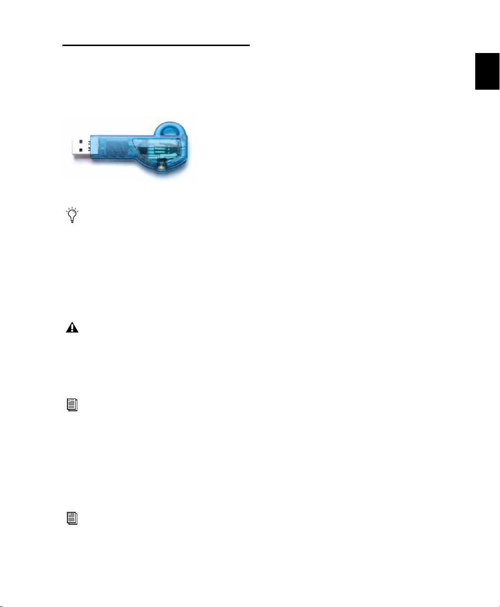
iLok USB Smart Key
Not all Pro Tools plug-ins require authorization. For example, no authorization is
required for free Pro_Tools plug-ins.
An iLok can hold over 100 licenses for all of your
iLok-enabled software. Once an iLok is authorized for a given piece of software, you can use
the iLok to authorize that software on any computer.
The iLok USB Smart Key is not supplied
with your plug-in or software option. You
can use the one included with certain
Pro Tools systems (such as Pro Tools|HDseries systems), or purchase one separately.
For more information, visit the iLok website
(www.iLok.com).
Authorizing Downloaded Plug-Ins
for Pro Tools
Authorizing Boxed Versions of
Plug-Ins for Pro Tools
If you purchased a boxed version of software, it
comes with an Activation Code (on the included
Activation Card).
To authorize a plug-in using an Activation Code:
1 If you do not have an iLok.com account, visit
www.iLok.com and sign up for an account.
2 Transfer the license for your plug-in to your
iLok.com account by doing the following:
• Visit www.avid.com/activation.
– and –
• Input your Activation Code (listed on your
Activation Card) and your iLok.com User
ID. Your iLok.com User ID is the name you
create for your iLok.com account.
3 Transfer the licenses from your iLok.com ac-
count to your iLok USB Smart Key by doing the
following:
• Insert the iLok into an available USB port
on your computer.
• Go to www.iLok.com and log in.
• Follow the on-screen instructions for transferring your licences to your iLok.
4 Launch Pro Tools.
5 If you have any installed unauthorized plug-
ins or software options, you are prompted to authorize them. Follow the on-screen instructions
to complete the authorization process.
If you downloaded a plug-in from the Avid Store
(store.avid.com), you authorize it by downloading a license from iLok.com to an iLok.
For more information, visit the iLok website
(www.iLok.com).
Chapter 2: Installing Plug-Ins 9
Page 26

Authorizing Plug-Ins on VENUE
Systems
After installing a plug-in on a VENUE system,
the system re-creates the list of available plugins. Whenever the racks initialize, the system
checks authorizations for all installed plug-ins.
If no previous authorization for a plug-in is recognized, you will be prompted to authorize the
the plug-in.
For complete instructions on authorizing
plug-ins for VENUE systems, see the
documentation that came with your
VENUE system.
VENUE supports challenge/response and iLok
USB Smart Key authorization, including pre-authorized iLoks and Activation Cards.
Challenge/Response Challenge/response authorization is only valid for the VENUE system the
plug-in is currently installed on. Challenge/response codes can be communicated using any
computer with Internet access.
iLok USB Smart Key Plug-Ins supporting web authorizations through iLok.com can be authorized for your iLok Smart Key from any computer with Internet access. This lets you take
your iLok and your plug-in authorizations anywhere, to use plug-ins installed on any system.
For more information, visit the iLok website
(www.iLok.com).
Mac OS X
To remove a plug-in:
1 Locate and open the Plug-Ins folder on your
Startup drive (Library/Application Support
/Digidesign/Plug-Ins).
2 Do one of the following:
• Drag the plug-in to the Trash and empty
the Trash.
– or –
• Drag the plug-in to the Plug-Ins (Unused)
folder.
Windows Vista and Windows 7
To remove a plug-in:
1 Choose Start > Control Panel.
2 Under Programs, click Uninstall a program.
3 Select the plug-in from the list of installed ap-
plications.
4 Click Uninstall.
5 Follow the on-screen instructions to remove
the plug-in.
Windows XP
To remove a plug-in:
1 Choose Start > Control Panel.
2 Double-click Add or Remove Programs.
Removing Plug-Ins for Pro Tools
If you need to remove a plug-in from your
Pro Tools system, follow the instructions for
your computer platform.
Audio Plug-Ins Guide10
3 Select the plug-in from the list of installed ap-
plications.
4 Click Remove.
5 Follow the on-screen instructions to remove
the plug-in.
Page 27

Removing Plug-Ins for VENUE Systems
Plug-Ins installed on VENUE systems can be disabled, uninstalled, or deleted. A plug-in that has
been disabled or uninstalled (but not deleted)
can be reinstalled without the CD-ROM or USB
drive containing the plug-in installers. Deleted
plug-ins, however, must be installed from installers located on either a USB drive or a
CD-ROM.
For complete instructions on uninstalling
plug-ins for VENUE systems, see the
documentation that came with your
VENUE system.
Chapter 2: Installing Plug-Ins 11
Page 28

Audio Plug-Ins Guide12
Page 29

Part II: DigiRack Plug-Ins
13
Page 30

14
Page 31

Chapter 3: Introduction
This section covers the DigiRack plug-ins that
are included with Pro Tools. These basic plug-ins
provide a comprehensive suite of digital signal
processing effects that include EQ, dynamics,
delay, and other essential functions.
The DigiRack plug-ins installed with Pro Tools
include:
• DigiRack Click
• DigiRack D-Fx plug-ins
•Chorus
•Flanger
•Multi-Tap Delay
• Ping-Pong Delay
• DigiRack Dither
• DigiRack D-Verb
• DigiRack Dynamics III
• Compressor/Limiter
• Expander/Gate
•De-Esser
• DigiRack EQ III
• 7 Band
•2–4Band
• 1 Band
• DigiRack ModDelay II
• DigiRack Pitch
• DigiRack Pitch Shift
• DigiRack POW-r Dither
• DigiRack ReWire
• DigiRack SignalGenerator
• DigiRack SignalTools
•SurroundScope
•PhaseScope
• DigiRack TimeAdjuster
• DigiRack Time Compression/Expansion
• DigiRack Time Shift
• DigiRack Trim
• Other DigiRack AudioSuite Plug-Ins
•DC Offset Removal
• Duplicate
•Gain
•Invert
• Normalize
• Reverse
Chapter 3: Introduction 15
Page 32

Audio Plug-Ins Guide16
Page 33

Chapter 4: Click
Click is a metronome plug-in that comes in
TDM and RTAS formats.
Click Controls
The Click plug-in creates an audio click during
session playback that you can use as a tempo reference when performing and recording. The
Click plug-in receives its tempo and meter data
from the Pro Tools application, enabling it to
follow any changes in tempo and meter in a session. The Click plug-in is a mono-only plug-in.
Several click sound presets are included.
Click plug-in
MIDI In LED Illuminates each time the Click
plug-in receives a click message from the
Pro Tools application, indicating the click
tempo.
Accented Controls the output level of the accent
beat (beat 1 of each bar) of the audio click.
Unaccented Controls the output level of the unaccented beats of the audio click.
Chapter 4: Click 17
Page 34

Creating a Click Track
To create a click track with the Click plug-in:
6 Ensure that the Options > Click is enabled.
7 Choose Track > Create Click Track.
Pro Tools creates a new Auxiliary Input track
named “Click” with the Click plug-in already inserted. In the Edit window, the track’s Track
Height is set to Mini.
To manually create a click track with the Click
plug-in:
1 Select Options > Click to enable the Click op-
tion (or enable the Metronome button in the
Transport).
2 Create new a mono Auxiliary Input track and
insert the Click plug-in.
3 Select a click sound preset.
4 Choose Setup > Click/Countoff and set the
Click and Countoff options as desired.
The Note, Velocity, Duration, and Output
options in this dialog are for use with MIDI
instrument-based clicks and do not affect
the Click plug-in.
Click Options dialog
5 Begin playback. A click is generated according
to the tempo and meter of the current session
and the settings in the Click/Countoff Options
dialog.
Refer to the Pro Tools Reference Guide for
more information on configuring Click options.
Audio Plug-Ins Guide18
Page 35

Chapter 5: DigiRack D-Fx Plug-Ins
D-Fx is a set of four AudioSuite plug-ins:
•Chorus
•Flanger
•Multi-Tap Delay
• Pin-Pong Delay
Chorus
(AudioSuite Only)
Chorus adds a shimmering quality to audio material by combining a time-delayed, pitchshifted copy of an audio signal with itself.
Chorus plug-in
The Chorus plug-in was formerly called
D-fx Chorus. It is fully compatible with all
settings and presets created for D-fx Chorus.
Gain Adjusts the input volume of the chorus to
prevent clipping or increase the level of the processed signal. This slider is set to a default of
+3 dB. If your source audio has been recorded
very close to peak level, this +3 dB default setting could cause clipping. Use this control to reduce the input level.
Selecting the Sum Inputs button sums the dry
input signals (mono or stereo) before processing
them. The dry signal then appears in the center
of the stereo field and the wet, effected signal
will be output in stereo.
When the Sum Inputs button is selected, the
LFO waveform on the right channel is automatically phase inverted to enhance the mono-stereo effect.
Sum Inputs button
Mix Adjusts the balance between the effected
signal and the original signal and controls the
depth of the effect. Mix is adjustable from 0% to
100%.
Low-Pass Filter Controls the cutoff frequency of
the Low-Pass Filter. Use this to attenuate the
high frequency content of the feedback signal.
The lower the setting, the more high frequencies
are removed from the feedback signal.
Chapter 5: DigiRack D-Fx Plug-Ins 19
Page 36

The range of the Low-Pass Filter is 20 Hz to
19.86 kHz, with a maximum value of Off (which
effectively means bypass).
Delay Sets the delay time between the original
signal and the chorused signal. The higher the
setting, the longer the delay and the wider the
chorusing effect. Delay is adjustable from 0–20
milliseconds.
LFO Rate Adjusts the rate of the LFO (low frequency oscillator) applied to the delayed signal
as modulation. The higher the setting, the more
rapid the modulation. You can select either a
sine wave or a triangle wave as a modulation
source, using the LFO Waveform selector.
LFO Width Adjusts the intensity of the LFO applied to the delayed signal as modulation. The
higher the setting, the more intense the modulation. Use the LFO Waveform selector to select
a sine or a triangle wave as a modulation source.
Flanger
(AudioSuite Only)
The Flanger animates and adds a swirling, moving quality to audio material by combing a timedelayed copy of an audio signal with itself.
The Flanger uses a through-zero flanging algorithm that results in a tape-like flanging effect.
This technique delays the original dry signal by
256 samples, then modulates the delayed signal
back and forth in time in relation to the dry signal, passing through its zero point on the way.
Feedback Controls the amount of feedback applied from the output of the delayed signal back
into its input. Negative settings provide a more
intense effect.
LFO Waveform Selects a sine wave or triangle
wave for the LFO. This affects the character of
the modulation. The sine wave has a gentler
ramp and peak than the triangle wave.
Audio Plug-Ins Guide20
Flanger plug-in
The Flanger plug-in was formerly called
D-fx Flanger. It is fully compatible with all
settings and presets created for D-fx
Flanger.
Gain Adjusts the input volume of the flanger to
prevent clipping or increase the level of the processed signal. This slider is set to a default of
+3 dB. If your source audio has been recorded
very close to peak level, this +3 dB default setting could cause clipping. Use this control to reduce the input level.
Selecting the Sum Inputs button sums the dry
input signals (mono and stereo) before processing them. The dry signal then appears in the
center of the stereo field and the wet, effected
signal will be output in stereo.
Page 37

When the Sum Inputs button is selected, the
LFO waveform on the right channel is phase inverted to enhance the mono-stereo effect.
Mix Adjusts the balance between the effected
signal and the original signal and controls the
depth of the effect. Mix is adjustable from 0% to
100%.
High-Pass Filter Controls the cutoff frequency of
the high-pass filter. Use this to attenuate the frequency content of the feedback signal and the
frequency response of the flanging. The higher
the setting, the more low frequencies are removed from the feedback signal.
LFO Rate Adjusts the rate of the LFO (low frequency oscillator) applied to the delayed signal
as modulation. The higher the setting, the more
rapid the modulation. You can select either a
sine wave or a triangle wave as a modulation
source, using the LFO Waveform selector.
LFO Width Adjusts the intensity of the LFO applied to the delayed signal as modulation. The
higher the setting, the more intense the modulation.
Multi-Tap Delay
(AudioSuite Only)
The Multi-Tap Delay adds up to four independently-controllable delays or taps to the original
audio signal. Use the Multi-tap delay to add spatialization or complex rhythmic echo effects to
audio material. You can individually control the
delay time and number of repetitions of each of
the four taps.
Feedback Controls the amount of feedback applied from the output of the delayed signal back
into its input. Negative settings provide a more
intense effect.
LFO Waveform Selects a sine wave or triangle
wave for the LFO. This affects the character of
the modulation. The sine wave has a gentler
ramp and peak than the triangle wave.
Multi-Tap Delay plug-in
The Multi-Tap Delay plug-in was formerly
called D-fx Multi-Tap Delay. It is fully
compatible with all settings and presets created for D-fx Multi-Tap Delay.
Chapter 5: DigiRack D-Fx Plug-Ins 21
Page 38

Gain Provides individual control of the input
level for each of the four delay lines (or “taps”).
Individually adjust the Gain for each of the four
taps, either to prevent clipping or to increase the
level of the processed signal.
Selecting the Sum Inputs button sums the dry
input signals (mono or stereo) before processing
them. The dry signal then appears in the center
of the stereo field and the wet, effected signal
will be output in stereo.
Feedback Provides individual control over the
amount of feedback applied from the output of
the delay into its input for each tap. It also controls the number of repetitions of the delayed
signal. For the feedback feature to function, the
Gain slider for that tap must be raised above its
lowest setting.
Pan Provides individual control over the apparent location of each of the four taps in the stereo
field.
Delay Sets the delay time between the original
signal and the delayed signal. The higher the
setting, the longer the delay. This control is adjustable from 0–1500 milliseconds (1.5 seconds).
Mix Adjusts the balance between the effected
signal and the original signal and controls the
depth of the effect. Mix is adjustable from 0% to
100%.
Ping-Pong Delay
(AudioSuite Only)
The Ping-Pong Delay plug-in adds a controllable
delay to the original audio signal. Use the PingPong delay to add spatialization, and panned
echo to audio material. This plug-in feeds back
delayed signals to their opposite channels, creating a characteristic ping-pong echo effect.
Ping-Pong Delay plug-in
The Ping-Pong Delay plug-in was formerly
called D-fx Ping-Pong Delay. It is fully compatible with all settings and presets created
for D-fx Ping-Pong Delay.
Gain Adjusts the input volume of the Ping-Pong
Delay to prevent clipping or to increase the level
of the processed signal.
Mix Adjusts the balance between the effected
signal and the original signal and controls the
depth of the effect. Mix is adjustable from 0% to
100%.
Delay Sets the delay time between the original
signal and the delayed signal. The higher the
setting, the longer the delay. This control is adjustable from 0–1500 milliseconds (1.5 seconds).
Low-Pass Filter Controls the cutoff frequency of
the low-pass filter. Use this to attenuate the high
frequency content of the feedback signal. The
lower the setting, the more high frequencies are
removed from the feedback signal.
Audio Plug-Ins Guide22
Page 39

The range of the Low-Pass Filter is 20 Hz to
19.86 kHz, with a maximum value of Off (which
effectively means bypass).
Selecting Audio for AudioSuite Delay Processing
Feedback Controls the amount of feedback applied from the output of the delay into its input.
It also controls the number of repetitions of the
delayed signal.
Cross-Feedback Cross-Feedback feeds the delayed signals to their opposite channel: The left
channel delay is fed to the right channel input
and vice-versa. The result is a stereo echo that
ping-pongs back and forth between the right
and left channels.
Because delays add additional material to the
end of selected audio (a delay tap), make a selection that is longer than the original source material so AudioSuite can write the additional delayed audio to the audio file.
Selecting only the original material, without
leaving additional space at the end results in the
delayed audio being cutoff at the end of the selection. To accommodate delayed audio that
comes after the source audio, place the region in
a track, and select the desired audio plus an
amount of blank space at the end of the region
equal to the amount of delay that you have
added in the plug-in. The plug-in will then have
space at the end of the region in which to write
the final delay.
Chapter 5: DigiRack D-Fx Plug-Ins 23
Page 40

Audio Plug-Ins Guide24
Page 41

Chapter 6: Dither
Dither is a dither-generation plug-in that comes
in TDM and RTAS formats.
The Dither plug-in minimizes quantization artifacts when reducing the bit depth of an audio
signal to 16-, 18-, or 20-bit resolution.
For more advanced dithering, use the DigiRack POW-r Dither plug-in. See
Chapter 14, “POW-r Dither.”
Dither plug-in
Whenever you are mixing down or bouncing to
disk and your destination bit depth is lower
than 24-bit, insert a dither plug-in on a Master
Fader track that controls the output mix.
Using a dither plug-in on a Master Fader is preferable to an Auxiliary Input because Master
Fader inserts are post-fader. As a post-fader insert, the dither plug-in can process changes in
Master Fader level.
For more information on using Dither, see
the Pro Tools Reference Guide.
The Dither plug-in has user-selectable bit resolution and a noise shaping on/off option.
If you are mixing down to an analog destination with any 24-bit capable interface,
you do not need to use Dither. This allows
maximum output fidelity from the 24-bit
digital-to-analog convertors of the interface.
Chapter 6: Dither 25
Page 42

Dither Controls
Bit Resolution
Use this pop-up menu to choose one of three
possible resolutions for the Dither processing.
Set this control to the maximum bit resolution
of your destination.
16-bit Recommended for output to digital devices with a maximum resolution of 16 bits,
such as DAT and CD recorders.
18-bit Recommended for output to digital devices with a maximum resolution of 18 bits.
20-bit Recommended for output to digital devices that support a full 20-bit recording data
path, such the Sony PCM-9000 optical mastering recorder, or the Alesis ADAT XT 20. Use this
setting for output to analog devices if you are using a 20-bit audio interface, such as the
882|20 I/O audio interface. The 20-bit setting
can also be used for output to digital effects devices that support 20-bit input and output, since
it provides for a lower noise floor and greater dynamic range when mixing 20-bit signals directly
into Pro Tools.
Noise Shaping
Noise shaping can further improve audio performance and reduce perceived noise inherent in
dithered audio. Noise shaping uses filtering to
shift noise away from frequencies in the middle
of the audio spectrum (around 4 kHz), where
the human ear is most sensitive.
The Noise Shaping button engages or disengages
Noise shaping. Noise shaping is on when the
button is highlighted in blue.
The DigiRack Dither plug-in only provides
eight channels of uncorrelated dithering
noise. If DigiRack Dither is used on more
than eight tracks, the dithering noise begins
to repeat and dither performance is impaired. For example, if two Quad DigiRack
Dithers are used, both Quad instances of
Dither will have all of their dither noise uncorrelated. However, any additional instances of the Dither plug-in will begin to
repeat the dithering noise.
Audio Plug-Ins Guide26
Page 43

Chapter 7: D-Verb
D-Verb is a studio-quality reverb provided in
TDM, RTAS, and AudioSuite formats.
The TDM version of the D-Verb plug-in is
not supported at 192 kHz; use the RTAS
version instead.
D-Verb Controls
D-Verb plug-in
Output Meter
The Output meter indicates the output level of
the processed signal. With the stereo version of
D-verb, it represents the summed stereo output.
It is important to note that this meter indicates
the output level of the signal—not the input
level. If this meter clips, it is possible that the
signal clipped on input before it reached
D-Verb. Monitor your send or insert signal levels
closely to help prevent this from happening.
Clip Indicator
The Clip indicator shows if clipping has occurred. It is a clip-hold indicator. If clipping occurs at any time during audio playback, the clip
lights remain on. To clear the clip indicator,
click it. With longer reverb times there is a
greater likelihood of clipping occurring as the
feedback element of the reverb builds up and approaches a high output level.
Input Level
The Input Level slider adjusts the input volume
of the reverb to prevent the possibility of clipping and/or increase the level of the processed
signal.
Mix
The Mix slider adjusts the balance between the
dry signal and the effected signal, giving you
control over the depth of the effect. This control
is adjustable from 100% to 0%.
Chapter 7: D-Verb 27
Page 44

Algorithm
This control selects one of seven reverb algorithms: Hall, Church, Plate, Room 1, Room 2,
Ambience, or Nonlinear. Selecting an algorithm
changes the preset provided for it. Switching the
Size setting changes characteristics of the algorithm that are not altered by adjusting the decay
time and other user-adjustable controls. Each of
the seven algorithms has a distinctly different
character:
Hall A good general purpose concert hall with a
natural character. It is useful over a large range
of size and decay times and with a wide range of
program material. Setting Decay to its maximum value will produce infinite reverberation.
Church A dense, diffuse space simulating a
church or cathedral with a long decay time,
high diffusion, and some pre-delay.
Nonlinear Produces a reverberation with a natural buildup and an abrupt cutoff similar to a
gate. This unnatural decay characteristic is particularly useful on percussion, since it can add
an aggressive characteristic to sounds with
strong attacks.
Size
The Size control, in conjunction with the Algorithm control, adjusts the overall size of the reverberant space. There are three sizes: Small, Medium, and Large. The character of the
reverberation changes with each of these settings (as does the relative value of the Decay setting). The Size buttons can be used to vary the
range of a reverb from large to small. Generally,
you should select an algorithm first, and then
choose the size that approximates the size of the
acoustic space that you are trying to create.
Plate Simulates the acoustic character of a
metal plate-based reverb. This type of reverb
typically has high initial diffusion and a relatively bright sound, making it particularly good
for certain percussive signals and vocal processing. Plate reverb has the general effect of thickening the initial sound itself.
Room 1 A medium-sized, natural, rich-sounding
room that can be effectively varied in size between very small and large, with good results.
Room 2 A smaller, brighter reverberant characteristic than Room 1, with a useful adjustment
range that extends to “very small.”
Ambient A transparent response that is useful for
adding a sense of space without adding a lot of
depth or density. Extreme settings can create interesting results.
Audio Plug-Ins Guide28
Diffusion
Diffusion sets the degree to which initial echo
density increases over time. High settings result
in high initial build-up of echo density. Low settings cause low initial buildup. This control interacts with the Size and Decay controls to affect
the overall reverb density. High settings of diffusion can be used to enhance percussion. Use low
or moderate settings for clearer and more natural-sounding vocals and mixes.
Decay
Decay controls the rate at which the reverb decays after the original direct signal stops. The
value of the Decay setting is affected by the Size
and Algorithm controls. This control can be set
to infinity on most algorithms for infinite reverb times.
Page 45

Pre-Delay
Pre-Delay determines the amount of time that
elapses between the original audio event and
the onset of reverberation. Under natural conditions, the amount of pre-delay depends on the
size and construction of the acoustic space, and
the relative position of the sound source and the
listener. Pre-Delay attempts to duplicate this
phenomenon and is used to create a sense of distance and volume within an acoustic space.
Long Pre-Delay settings place the reverberant
field behind rather than on top of the original
audio signal.
Hi Frequency Cut
Hi Frequency Cut controls the decay characteristic of the high frequency components of the
reverb. It acts in conjunction with the Low-Pass
Filter control to create the overall high frequency contour of the reverb. When set relatively low, high frequencies decay more quickly
than low frequencies, simulating the effect of air
absorption in a hall. The maximum value of this
control is Off (which effectively means bypass).
Low-Pass Filter
Low-Pass Filter controls the overall high frequency content of the reverb by setting the frequency above which a 6 dB per octave filter attenuates the processed signal. The maximum
value of this control is Off (which effectively
means bypass).
Chapter 7: D-Verb 29
Page 46

Audio Plug-Ins Guide30
Page 47

Chapter 8: Dynamics III
Gain
Reduction
meter
Threshold
arrow
Phase
Invert
Input
meter
Output meter
Peak hold
indicators
Peak hold
indicators
Dynamics III is a suite of three dynamics plugins that come in TDM, RTAS, and AudioSuite
formats:
• Compressor/Limiter
• Expander/Gate
•De-Esser
All Dynamics III modules are available in TDM,
RTAS, and AudioSuite formats.
Shared Compressor/Limiter and Expander/Gate Features
The following parts of the user interface are
shared between the Compressor/Limiter and Expander/Gate Dynamics III plug-ins.
Levels Section
Dynamics III supports 44.1 kHz, 48 kHz,
88.2 kHz, 96 kHz, 176.4 kHz and 192 kHz sample rates. Compressor/Limiter and Expander/Gate modules work with mono, stereo,
and greater-than-stereo multichannel formats
up to 7.1. The De-Esser module works with
mono and stereo formats only.
In addition to standard controls in each module, Dynamics III also provides a graph to track
the gain transfer curve in the Compressor/Limiter and Expander/Gate plug-ins, and a frequency graph to display which frequencies trigger the De-Esser and which frequencies will be
gain reduced.
The indicators and controls in the Levels section
let you track input, output, and gain reduction
levels, as well as work with phase invert and the
threshold setting.
See “De-Esser Levels Section” on page 41
for more information on De-Esser III Input/Output Level controls.
I/O Meter display (stereo instance shown)
Chapter 8: Dynamics III 31
Page 48

Input and Output Meters
Input and
Output Meter
buttons
Gain Reduction Meter
The Input (In) and Output (Out) meters show
peak signal levels before and after dynamics processing:
Green Indicates nominal levels.
Yello w Indicates pre-clipping levels, starting at
–6 dB below full scale.
Red Indicates full scale levels (clipping).
The clip indicators at the top of the Output meters indicate clipping at the input or output
stage of the plug-in. Clip indicators can be
cleared by clicking the indicator.
The Input and Output meters display differently depending on the type of track (mono,
stereo, or multichannel) on which the plugin has been inserted.
When Side-Chain Listen is enabled, the
Output meter only displays the levels of the
side-chain signal. See “Side-Chain Listen”
on page 43.
Toggling Multichannel Input and Output Meters
With multichannel track types LCRS and
higher, both Input and Output meters cannot
be shown at the same time. Click either the Input or Output button to display the appropriate
level meter. The Input/Output meters display is
toggled to Output by default.
The Gain Reduction (GR) meter indicates the
amount the input signal is attenuated (in dB)
and shows different colors during dynamics processing:
Light Orange Indicates that gain reduction is
within the “knee” and has not reached the full
ratio of compression.
Dark Orange Indicates that gain reduction is being applied at the full ratio (for example, 2:1).
Threshold Arrow
The orange Threshold arrow next to the Input
meter indicates the current threshold, and can
be dragged up or down to adjust the threshold.
When a multichannel instance of the plug-in
has been configured to show only the Output
meter, the Threshold arrow is not displayed.
Phase Invert
The Phase Invert button inverts the phase (polarity) of the input signal, to help compensate
for phase anomalies that can occur either in
multi-microphone environments or because of
mis-wired balanced connections.
Input and Output meter buttons
Audio Plug-Ins Guide32
Page 49

LFE Enable
Input signal
level (x-axis)
Output signal
level (y-axis)
Threshold
(Pro Tools HD and Pro Tools LE with Complete
Production Toolkit Only)
The LFE Enable button (located in the Options
section) is on by default, and enables plug-in
processing of the LFE (low frequency effects)
channel on a multichannel track formatted for
5.1, 6.1, or 7.1 surround formats. To disable LFE
processing, deselect this button.
Use this graph as a visual guideline to see how
much dynamics processing you are applying.
LFE Enable button (Compressor/Limiter III shown)
The LFE Enable button is not available if
the plug-in is not inserted on an applicable
track.
Dynamics Graph Display
The Dynamics Graph display—used with the
Compressor/Limiter and Expander/Gate plugins—shows a curve that represents the level of
the input signal (on the x–axis) and the level of
the output signal (on the y–axis). The orange
vertical line represents the threshold.
Dynamics graph display
The Compressor/Limiter and Expander/Gate
plug-ins also feature an animated, multi-color
cursor in their gain transfer curve displays.
The gain transfer curve of the Compressor/Limiter and Expander/Gate plug-ins shows a moving ball cursor that shows the amount of input
gain (x-axis) and gain reduction (y-axis) being
applied to the incoming signal.
Gain transfer curve and cursor showing amount of
compression
Chapter 8: Dynamics III 33
Page 50

To indicate overshoots (when an incoming signal peak is too fast for the current compression
setting) the cursor temporarily leaves the gain
transfer curve.
The cursor changes color to indicate the amount
of compression applied, as follows:
Dynamics III Plug-In Compression Amount
Cursor Color Compression Amount
white no compression
light orange below full ratio
dark orange full ratio amount
See “De-Esser Frequency Graph Display” on
page 42 for information on using the De-Esser’s graph display.
Side-Chain Section
For information on using the Side-Chain section
of the Compressor/Limiter or Expander/Gate,
see “Using the Side-Chain Input in Dynamics
III” on page 43.
Compressor/Limiter III
The Compressor/Limiter plug-in applies either
compression or limiting to audio material, depending on the ratio of compression used.
Compressor/Limiter III
About Compression
Compression reduces the dynamic range of signals that exceed a chosen threshold by a specific
amount. The Threshold control sets the level
that the signal must exceed to trigger compression. The Attack control sets how quickly the
compressor responds to the “front” of an audio
signal once it crosses the selected threshold. The
Release control sets the amount of time that it
takes for the compressor’s gain to return to its
original level after the input signal drops below
the selected threshold.
To use compression most effectively, the attack
time should be set so that signals exceed the
threshold level long enough to cause an increase
in the average level. This helps ensure that gain
reduction does not decrease the overall volume
too drastically, or eliminate desired attack transients in the program material.
Of course, compression has many creative uses
that break these rules.
Audio Plug-Ins Guide34
Page 51

About Limiting
Compressor/Limiter III Controls
Limiting prevents signal peaks from ever exceeding a chosen threshold, and is generally
used to prevent short-term peaks from reaching
their full amplitude. Used judiciously, limiting
produces higher average levels, while avoiding
overload (clipping or distortion), by limiting
only some short-term transients in the source
audio. To prevent the ear from hearing the gain
changes, extremely short attack and release
times are used.
Limiting is used to remove only occasional
peaks because gain reduction on successive
peaks would be noticeable. If audio material
contains many peaks, the threshold should be
raised and the gain manually reduced so that
only occasional, extreme peaks are limited.
Limiting generally begins with the ratio set at
10:1 and higher. Large ratios effectively limit the
dynamic range of the signal to a specific value
by setting an absolute ceiling for the dynamic
range.
This section describes controls for the Compressor/Limiter plug-in.
Input/Output Level Meters
The Input and Output meters show peak signal
levels before and after dynamics processing. See
“Levels Section” on page 31 for more information.
Unlike scales on analog compressors, metering
scales on a digital device reflect a 0 dB value that
indicates full scale (fs)—the full-code signal
level. There is no headroom above 0 dB.
Compressor/Limiter Graph Display
The Dynamics Graph display lets you visually
see how much expansion or gating you are applying to your audio material. See “Dynamics
Graph Display” on page 33.
Threshold
The Threshold (Thresh) control sets the level
that an input signal must exceed to trigger compression or limiting. Signals that exceed this
level will be compressed. Signals that are below
it will be unaffected.
This control has an approximate range of –60 dB
to 0 dB, with a setting of 0 dB equivalent to no
compression or limiting. The default value for
the Threshold control is –24 dB.
Chapter 8: Dynamics III 35
Page 52

An orange arrow on the Input meter indicates
Threshold
arrow
Threshold
the current threshold, and can also be dragged
up or down to adjust the threshold setting.
Attack
The Attack control sets the attack time, or the
rate at which gain is reduced after the input signal crosses the threshold.
The smaller the value, the faster the attack. The
faster the attack, the more rapidly the Compressor/Limiter applies attenuation to the signal. If
you use fast attack times, you should generally
use a proportionally longer release time, particularly with material that contains many peaks
in close proximity.
Threshold arrow on input meter
The Dynamics Graph display also shows the
threshold as an orange vertical line.
Threshold indicator on Dynamics Graph display
This control ranges from –60 dB (lowest gain) to
0 dB (highest gain).
Ratio
The Ratio control sets the compression ratio, or
the amount of compression applied as the input
signal exceeds the threshold. For example, a 2:1
compression ratio means that a 2 dB increase of
level above the threshold produces a 1 db increase in output.
This control ranges from 10 μs (fastest attack
time) to 300 ms (slowest attack time).
Release
The Release control sets the length of time it
takes for the Compressor/Limiter to be fully deactivated after the input signal drops below the
threshold.
Release times should be set long enough that if
signal levels repeatedly rise above the threshold,
the gain reduction “recovers” smoothly. If the
release time is too short, the gain can rapidly
fluctuate as the compressor repeatedly tries to
recover from the gain reduction. If the release
time is too long, a loud section of the audio material could cause gain reduction that continues
through soft sections of program material without recovering.
This control ranges from 5 ms (fastest release
time) to 4 seconds (slowest release time).
This control ranges from 1:1 (no compression)
to 100:1 (hard limiting).
Audio Plug-Ins Guide36
Page 53

Knee
Hard knee Soft knee
Gain
The Knee control sets the rate at which the compressor reaches full compression once the
threshold has been exceeded.
As you increase this control, it goes from applying “hard-knee” compression to “soft-knee”
compression:
• With hard-knee compression, compression
begins when the input signal exceeds the
threshold. This can sound abrupt and is ideal
for limiting.
• With soft-knee compression, gentle compression begins and increases gradually as the input signal approaches the threshold, and
reaches full compression after exceeding the
threshold. This creates smoother compression.
The Gain control lets you boost overall output
gain to compensate for heavily compressed or
limited signals.
This control ranges from 0 dB (no gain boost) to
+40 dB (loudest gain boost), with the default
value at 0 dB.
For more information on the LFE channel,
refer to the Pro Tools Reference Guide.
Side-Chain Section
The side-chain is the split-off signal used by the
plug-in’s detector to trigger dynamics processing. The Side-Chain section lets you toggle the
side-chain between the internal input signal or
an external key input, and tailor the equalization of the side-chain signal so that the triggering of dynamics processing becomes frequencysensitive. See “Using the Side-Chain Input in
Dynamics III” on page 43.
Graph examples of hard and soft knee compression
For example, a Knee setting of 10 dB would be
the gain range over which the ratio gradually increased to the set ratio amount.
The Gain Reduction meter displays light orange
while gain reduction has not exceeded the knee
setting, and switches to dark orange when gain
reduction reaches the full ratio.
This control ranges from 0 db (hardest response)
to 30 db (softest response).
Chapter 8: Dynamics III 37
Page 54

Expander/Gate III
The Expander/Gate plug-in applies expansion or
gating to audio material, depending on the ratio
setting.
Expander/Gate III
About Expansion
Expansion decreases the gain of signals that fall
below a chosen threshold. They are particularly
useful for reducing noise or signal leakage that
creeps into recorded material as its level falls, as
often occurs in the case of headphone leakage.
Expander/Gate III Controls
This section describes controls for the Expander/Gate plug-in.
Input/Output Level Meters
The Input and Output meters show peak signal
levels before and after dynamics processing. See
“Levels Section” on page 31 for more information.
Expander/Gate Dynamics Graph Display
The Dynamics Graph display lets you visually
see how much expansion or gating you are applying to your audio material. See “Dynamics
Graph Display” on page 33.
Look Ahead Button
Normally, dynamics processing begins when
the level of the input signal crosses the threshold. When the Look Ahead button is enabled,
dynamics processing begins 2 milliseconds before the level of the input signal crosses the
threshold.
About Gating
Gating silences signals that fall below a chosen
threshold. To enable gating, simply set the Ratio
and Range controls to their maximum values.
Expanders can be thought of as soft noise gates
since they provide a gentler way of reducing
noisy low-level signals than the typically abrupt
cutoff of a gate.
Audio Plug-Ins Guide38
Look Ahead control
The Look Ahead control is useful for avoiding
the loss of transients that may have been otherwise cut off or trimmed in a signal.
Page 55

Threshold
Threshold
arrow
Threshold
Ratio
The Threshold (Thresh) control sets the level below which an input signal must fall to trigger expansion or gating. Signals that fall below the
threshold will be reduced in gain. Signals that
are above it will be unaffected.
An orange arrow on the Input meter indicates
the current threshold, and can also be dragged
up or down to adjust the threshold setting.
Threshold arrow on Input meter
The Dynamics Graph display also shows the
threshold as an orange vertical line.
The Ratio control sets the amount of expansion.
For example, if this is set to 2:1, it will lower signals below the threshold by one half. At higher
ratio levels (such as 30:1 or 40:1) the Expander/Gate functions like a gate by cutting off
signals that fall below the threshold. As you adjust the ratio control, refer to the built-in graph
to see how the shape of the expansion curve
changes.
This control ranges from 1:1 (no expansion) to
100:1 (gating).
Attack
The Attack control sets the attack time, or the
rate at which gain is reduced after the input signal crosses the threshold. Use this along with
the Ratio setting to control how soft the Expander’s gain reduction curve is.
This control ranges from 10 μs (fastest attack
time) to 300 ms (slowest attack time).
Hold
Threshold indicator on Dynamics Graph display
This control has an approximate range of –60 dB
to 0 dB, with a setting of 0 dB equivalent to no
compression or limiting. The default value for
the Threshold control is –24 dB.
The Hold control specifies the duration (in seconds or milliseconds) during which the Expander/Gate will stay in effect after the initial attack occurs. This can be used as a function to
keep the Expander/Gate in effect for longer periods of time with a single crossing of the threshold. It can also be used to prevent gate chatter
that may occur if varying input levels near the
threshold cause the gate to close and open very
rapidly.
This control ranges from 5 ms (shortest hold) to
4 seconds (longest hold).
Chapter 8: Dynamics III 39
Page 56

Release
The Release control sets how long it takes for the
gate to close after the input signal falls below the
threshold level and the hold time has passed.
This control ranges from 5 ms (fastest release
time) to 4 seconds (slowest release time).
Range
The Range control sets the depth of the Expander/Gate when closed. Setting the gate to
higher range levels allows more and more of the
gated audio that falls below the threshold to
peek through the gate at all times.
This control ranges from –80 dB (lowest depth)
to 0 dB (highest depth).
Side-Chain Section
The side-chain is the split-off signal used by the
plug-in’s detector to trigger dynamics processing. The Side-Chain section lets you toggle the
side-chain between the internal input signal or
an external key input, and tailor the equalization of the side-chain signal so that the triggering of dynamics processing becomes frequencysensitive. See “Using the Side-Chain Input in
Dynamics III” on page 43.
De-Esser III
De-Esser III
The De-Esser reduces sibilants and other high
frequency noises that can occur in vocals, voiceovers, and wind instruments such as flutes.
These sounds can cause peaks in an audio signal
and lead to distortion.
The De-Esser reduces these unwanted sounds using fast-acting compression. The Threshold control sets the level above which compression
starts, and the Frequency (Freq) control sets the
frequency band in which the De-Esser operates.
Audio Plug-Ins Guide40
Page 57

Using De-Essing Effectively
Gain
Reduction
meter
Input
meter
Output meter
De-Esser III Controls
To use de-essing most effectively, insert the DeEsser after compressor or limiter plug-ins.
The Frequency control should be set to remove
sibilants (typically the 4–10 kHz range) and not
other parts of the signal. This helps prevent deessing from changing the original character of
the audio material in an undesired manner.
Similarly, the Range control should be set to a
level low enough so that de-essing is triggered
only by sibilants. If the Range is set too high, a
loud, non-sibilant section of audio material
could cause unwanted gain reduction or cause
sibilants to be over-attenuated.
To improve de-essing of material that has both
very loud and very soft passages, automate the
Range control so that it is lower on soft sections.
The De-Esser has no control to directly adjust the threshold level (the level that an input signal must exceed to trigger de-essing).
The amount of de-essing will vary with the
input signal.
This section describes controls for the De-Esser
plug-in.
De-Esser Levels Section
These controls let you track input, output, and
gain reduction levels.
De-Esser III I/O Meter display
Input and Output Meters
The Input and Output meters show peak signal
levels before and after dynamics processing:
Green Indicates nominal levels.
Yello w Indicates pre-clipping levels, starting at
–6 dB below full scale.
Red Indicates full scale levels (clipping).
The Clip indicators at the top of each meter indicate clipping at the input or output stage of
the plug-in. Clip indicators can be cleared by
clicking the indicator.
Chapter 8: Dynamics III 41
Page 58

Gain Reduction Meter
Frequency
(x-axis)
Gain
(y-axis)
Frequency
Range
Current gain
reduction
Listen
The Gain Reduction meter indicates the amount
the input signal is attenuated, in dB. This meter
shows different colors during de-essing:
Light Orange Indicates that gain reduction is being applied, but has not reached the maximum
level set by the Range control.
Dark Orange Indicates that gain reduction has
reached the maximum level set by the Range
control.
Frequency
The Frequency (Freq) control sets the frequency
band in which the De-Esser operates. When HF
Only is disabled, gain is reduced in frequencies
within the specified range. When HF Only is enabled, the gain of frequencies above the specified value will be reduced.
This control ranges from 500 Hz (lowest frequency) to 16 kHz (highest frequency).
Range
The Range control defines the maximum
amount of gain reduction possible when a signal
is detected at the frequency set by the Frequency
control.
When enabled, the Listen button lets you monitor the sibilant peaks used by the De-Esser as a
side-chain to trigger compression. This is useful
for listening only to the sibilance for fine-tuning
De-Esser controls. To monitor the whole output
signal without this filtering, deselect the Listen
button.
De-Esser Frequency Graph Display
The De-Esser Frequency Graph display shows a
curve that represents the level of gain reduction
(on the y-axis) for the range of the output signal's frequency (on the x-axis). The white line
represents the current Frequency setting, and
the animated orange line represents the level of
gain reduction being applied to the signal.
Use this graph as a visual guideline to see how
much dynamics processing you are applying at
different points in the frequency spectrum.
This control ranges from –40 dB (maximum deessing) to 0 dB (no de-essing).
HF Only
When the HF Only button is enabled, gain reduction is applied only to the active frequency
band set by the Frequency control. When the HF
Only button is disabled, the De-Esser applies
gain reduction to the entire signal.
Audio Plug-Ins Guide42
De-Esser graph display
Page 59

Using the Side-Chain Input in
External Key Side-Chain Listen
HF Filter
Enable
LF Filter
Enable
Dynamics III
(Compressor/Limiter
and Expander/Gate Only)
Dynamics processors typically use the detected
amplitude of their input signal to trigger gain reduction. This split-off signal is known as the
side-chain. The Compressor/Limiter and Expander/Gate plug-ins feature external key capabilities and filters for the side-chain.
With external key side-chain processing, you
trigger dynamics processing using an external
signal (such as a separate reference track or audio source) instead of the input signal. This external source is known as the key input.
Side-Chain Section
The Side-Chain section lets you toggle the sidechain between the internal input signal or an
external key input, listen to the side-chain, and
tailor the equalization of the side-chain signal so
that the triggering of dynamics processing becomes frequency-sensitive.
With side-chain filters, you can make dynamics
processing more or less sensitive to certain frequencies. For example, you might configure the
side-chain so that certain lower frequencies on a
drum track trigger dynamics processing.
Compressor/Limiter and Expander/Gate Side-Chain
External Key
The External Key toggles external side-chain
processing on or off. When this button is highlighted, the plug-in uses the amplitude of a separate reference track or external audio source to
trigger dynamics processing. When this button
is dark gray, the External Key is disabled and the
plug-in uses the amplitude of the input signal to
trigger dynamics processing.
Side-Chain Listen
When enabled, this control lets you listen to the
internal or external side-chain input by itself, as
well as monitor its levels with the Output meter.
This is especially useful for fine-tuning the plugin’s filter settings or external key input.
Side-Chain Listen is not saved with other
plug-in presets.
Chapter 8: Dynamics III 43
Page 60

HF and LF Filter Enable Buttons
HF Filter
Enable
HF
Frequency
Control
Low-
Pass
HF
Band-
Pass
LF Filter
Enable
LF
Frequency
HighPass
LF
Band-
Pass
HF Frequency Control
The HF Filter Enable and LF Filter Enable buttons toggle the corresponding filter in or out of
the side-chain. When this button is highlighted,
the filter is applied to the side-chain signal.
When this button is dark gray, the filter is bypassed and available for activation.
HF and LF Filter Side-Chain
High-Frequency (HF) Filter Type
The HF filter section lets you filter higher frequencies out of the side-chain signal so that
only certain bands of high frequencies or lower
frequencies pass through to trigger dynamics
processing. The HF side-chain filter is switchable
between Band-Pass and Low-Pass filters.
Band-Pass Filter Makes triggering of dynamics
processing more sensitive to frequencies within
the narrow band centered around the Frequency
setting, and rolling off at a slope of 12 dB per octave.
Low-Pass Filter Makes triggering of dynamics
processing more sensitive to frequencies below
the Frequency setting rolling off at a slope of
12 dB per octave.
The Frequency control sets the frequency position for the Band-Pass or Low-Pass filter, and
ranges from 80 Hz to 20 kHz.
Low-Frequency (LF) Filter Type
The LF filter section lets you filter lower frequencies out of the side-chain signal so that only certain bands of low frequencies or higher frequencies are allowed to pass through to trigger
dynamics processing. The LF side-chain is switchable between Band-Pass and High-Pass filters.
Band-Pass Filter Makes triggering of dynamics
processing more sensitive to frequencies within
the narrow band centered around the Frequency
setting, and rolling off at a slope of 12 dB per octave.
High-Pass Filter Makes triggering of dynamics
processing more sensitive to frequencies above
the Frequency setting rolling off at a slope of
12 dB per octave.
LF Frequency Control
The Frequency control sets the frequency position for the Band-Pass or High-Pass filter, and
ranges from 25 Hz to 4 kHz.
Audio Plug-Ins Guide44
Page 61

Using an External Key Input for
External Key Side-Chain Listen
External Key Side-Chain Listen
Side-Chain Processing
Using a Filtered Input Signal for
Side-Chain Processing
To use a filtered or unfiltered external key input to
trigger dynamics processing:
1 Click the Key Input selector and select the in-
put or bus carrying the audio from the reference
track or external audio source.
Selecting a Key Input
2 Click External Key to activate external side-
chain processing.
Side-Chain section
3 To listen to the signal that will be used to con-
trol side-chain input, click Side-Chain Listen to
enable it (highlighted).
4 To filter the key input so that only specific fre-
quencies trigger the plug-in, use the HF and LF
controls to select the desired frequency range.
5 Begin playback. The plug-in uses the input or
bus that you chose as an external key input to
trigger its effect.
To use the filtered input signal to trigger dynamics
processing:
1 Ensure the Key Input selector is set to No Key
Input.
Key Input selector
2 Ensure that the External Key button is dis-
abled (dark gray).
Side-Chain section
3 To listen to the signal that will be used to con-
trol side-chain input, click Side-Chain Listen to
enable it (highlighted).
4 To filter the side-chain input so that only spe-
cific frequencies within the input signal trigger
the plug-in, use the HF and LF controls to select
the desired frequency range.
5 Begin playback. The plug-in uses the filtered
input signal to trigger dynamics processing.
6 To fine-tune side-chain triggering, adjust the
plug-in controls.
6 Adjust the plug-in’s Threshold (Thresh) con-
trol to fine-tune external key input triggering.
7 Adjust other controls to achieve the desired ef-
fect.
Chapter 8: Dynamics III 45
Page 62

Audio Plug-Ins Guide46
Page 63

Chapter 9: EQ III
The EQ III plug-in provides a high-quality
7 Band, 2–4 Band, or 1 Band EQ for adjusting
the frequency spectrum of audio material.
EQ III is available in the following formats:
• 7 Band: TDM, RTAS, and AudioSuite
• 2–4 Band: TDM and RTAS only
• 1 Band: TDM, RTAS, and AudioSuite
EQ III supports all Pro Tools session sample
rates: 192 kHz, 176.4 kHz, 96 kHz, 88.2 kHz,
48 kHz, and 44.1 kHz. EQ III operates as a
mono, multi-mono, or stereo plug-in.
EQ III can be operated from the following control surfaces:
• D-Command
• D-Control
• ProControl
•C|24
• Control|24
• Digi 003
• Digi 002
• Command|8
• Mackie HUI-compatible controllers
By choosing from the 7 Band, 2–4 Band, or
1 Band versions of the EQ III plug-in, you can
use only the number of EQ bands you need for
each track, conserving DSP capacity on
Pro Tools|HD systems.
EQ III Configurations
The EQ III plug-in appears as three separate
choices in the plug-in insert pop-up menu and
in the AudioSuite menu:
• 1 Band (“1-Band EQ 3”)
• 2–4 Band (“4-Band EQ 3”)
• 7 Band (“7-Band EQ 3”)
EQ III has a Frequency Graph display that shows
the response curve for the current EQ settings
on a two-dimensional graph of frequency and
gain. The frequency graph display also lets you
modify frequency, gain and Q settings for individual EQ bands by dragging their corresponding points in the graph.
Chapter 9: EQ III 47
Page 64

1 Band EQ
The 1 Band EQ is available in TDM, RTAS, and
AudioSuite formats.
The 1 Band EQ has its own window, with six selectable filter types.
1 Band EQ window
EQ III Controls
Adjusting EQ III Controls
You can adjust the EQ III plug-in controls by
any of the following methods:
Dragging Plug-In Controls
The rotary controls on the EQ III plug-in can be
adjusted by dragging over them horizontally or
vertically. Dragging up or to the right increments the control. Dragging down or to the left
decrements the control.
7 Band EQ and 2–4 Band EQ
The 7 Band EQ is available in TDM, RTAS, and
AudioSuite formats. The 2–4 Band EQ is available in TDM and RTAS formats only.
The 7 Band EQ and the 2–4 Band EQ share the
same window and identical controls, but with
the 2–4 Band EQ, a limited number of the seven
available bands can be active at the same time.
7 Band EQ and 2–4 Band EQ window
Dragging a plug-in control
Typing Control Values
You can enter control values directly by clicking
in the corresponding text box, typing a value,
and pressing Enter (Windows) or Return (Mac).
Typing a control value
Inverting Filter Gain
(Peak EQ Bands Only)
Gain values can be inverted on any Peak EQ
band by Shift-clicking its control dot in the Frequency Graph display, or its Gain knob in the
plug-in window. This changes a gain boost to a
cut (+9 to –9) or a gain cut to a boost (–9 to +9).
Gain values cannot be inverted on Notch, HighPass, Low-Pass, or shelving bands.
Audio Plug-Ins Guide48
Page 65

Dragging in the Frequency Graph
Display
You can adjust the following by dragging the
control points directly in the Frequency Graph
display:
Resetting Controls to Default Values
You can reset any on-screen control to its default value by Alt-clicking (Windows) or Optionclicking (Mac OS) directly on the control or on
its corresponding text box.
Frequency Dragging a control point to the right
increases the Frequency setting. Dragging a control point to the left decreases the Frequency setting.
Gain Dragging a control point up increases the
Gain setting. Dragging a control point down decreases the Gain setting.
Q Start-dragging (Windows) or Control-dragging (Mac) a control point up increases the Q
setting. Start-dragging (Windows) or Controldragging (Mac) a control point down decreases
the Q setting.
Using Band-Pass Mode
You can temporarily set any EQ III control to
Band-Pass monitoring mode. Band-Pass mode
cuts monitoring frequencies above and below
the Frequency setting, leaving a narrow band of
mid-range frequencies. It is especially useful for
adjusting limited bandwidth in order to solo
and fine-tune each individual filter before reverting the control to notch filter or peaking filter type operations.
Band-Pass mode does not affect EQ III Gain
controls.
To switch an EQ III control to Band-Pass mode:
Hold Start+Shift (Windows) or Control+Shift
(Mac), and drag any rotary control or control
point horizontally or vertically.
Dragging a control point in the Frequency Graph display
Adjusting Controls with Fine Resolution
Controls and control points can be adjusted
with fine resolution by holding the Control key
(Windows) or the Command key (Mac) while
adjusting the control.
EQ III interactive graph displaying Band-Pass mode
When monitoring in Band-Pass mode, the Frequency and Q controls function differently.
Frequency Sets the frequency above and below
which other frequencies are cut off, leaving a
narrow band of mid-range frequencies.
Chapter 9: EQ III 49
Page 66

Q Sets the width of the narrow band of mid-
Input
Output Gain
Input and Output Meters
Gain
Input
Polarity
Clip
Indicators
Control
Control
Control
range frequencies centered around the Frequency setting.
To switch an EQ III control out of Band-Pass mode:
Release Start+Shift (Windows) or Con-
trol+Shift (Mac).
Using a Control Surface
EQ III can be controlled from any supported
control surface, including our D-Control, DCommand, ProControl, C|24, 003, Digi 002, or
Command|8. Refer to the guide that came with
the control surface for details.
Input Gain Control
The Input Gain control sets the input gain of the
plug-in before EQ processing, letting you make
up gain or prevent clipping at the plug-in input
stage.
Output Gain Control
(7 Band EQ and 2–4 Band EQ Only)
The Output Gain control sets the output gain after EQ processing, letting you make up gain or
prevent clipping on the channel where the plugin is being used.
Input Polarity Control
I/O Controls
The following Input and Output controls are
found on all EQ III configurations, except where
noted otherwise.
I/O controls and meters for 7 Band EQ and
2–4 Band EQ (top) and 1 Band EQ (bottom)
The Input Polarity button inverts the polarity of
the input signal, to help compensate for phase
anomalies occurring in multi-microphone environments, or because of mis-wired balanced
connections.
Input and Output Meters
(7 Band EQ and 2–4 Band EQ Only)
The plasma-style Input and Output meters show
peak signal levels before and after EQ processing, and indicate them as follows:
Green Indicates nominal levels
Yello w Indicates pre-clipping levels, starting at
–6 dB below full scale
Red Indicates full scale levels (clipping)
When using the stereo version of EQ III, the Input and Output meters display the sum of the
left and right channels.
The Clip indicators at the far right of each meter
indicate clipping at the input or output stage of
the plug-in. Clip indicators can be cleared by
clicking the indicator.
Audio Plug-Ins Guide50
Page 67

EQ Band Controls
Frequency
control
Band
Enable
button
Gain
control
Q
control
EQ type
selector
Band Gain Control
The individual EQ bands on each EQ III configuration have some combination of the following controls, as noted below.
EQ Band controls (7 Band EQ Low-Mid band shown)
EQ Type Selector
On the 1 Band EQ, the EQ Type selector lets you
choose any one of six available filter types:
High-Pass, Notch, High-Shelf, Low-Shelf, Peak,
and Low-Pass.
On the 7 Band EQ and the 2–4 Band EQ, the
HPF, LPF, LF, and HF sections have EQ Type selectors to toggle between the two available filter
types in each section.
Band Enable Button
(7 Band EQ and 2–4 Band EQ Only)
Each Peak and Shelf EQ band has a Gain control
for boosting or cutting the corresponding frequencies. Gain controls are not used on HighPass, Low-Pass, or Notch filters.
Frequency Control
Each EQ band has a Frequency control that sets
the center frequency (Peak, Shelf and Notch
EQs) or the cutoff frequency (High-Pass and
Low-Pass filters) for that band.
Q Control
Peak and Notch On Peak and Notch bands, the
Q control changes the width of the EQ band.
Higher Q values represent narrower bandwidths. Lower Q values represent wider bandwidths.
Shelf On Shelf bands, the Q control changes the
Q of the shelving filter. Higher Q values represent steeper shelving curves. Lower Q values represent broader shelving curves.
Band Pass On High-Pass and Low-Pass bands,
the Q control lets you select from any of the following Slope values: 6 dB, 12 dB, 18 dB, or
24 dB per octave.
The Band Enable button on each EQ band toggles the corresponding band in and out of circuit. When a Band Enable button is highlighted,
the band is in circuit. When a Band Enable button is dark gray, the band is bypassed and available for activation. On the 2–4 Band EQ, when a
Band Enable button is light gray, the band is bypassed and unavailable.
Chapter 9: EQ III 51
Page 68

Frequency Graph Display
High-Pass
control dot
Low-Mid
control dot
High-Mid
control dot
Low-Pass
control dot
(gray) (brown) (green) (gray)
Low
control dot
(red)
Mid
control dot
(yellow)
High
control dot
(blue)
Frequency
response
curve
(7 Band EQ and 2–4 Band EQ Only)
The Frequency Graph display in the 7 Band EQ and the 2–4 Band EQ shows a color-coded control dot
that corresponds to the color of the Gain control for each band. The filter shape of each band is similarly color-coded. The white frequency response curve shows the contribution of each of the enabled
filters to the overall EQ curve.
Frequency Graph display for the 7 Band EQ
Audio Plug-Ins Guide52
Page 69

7 Band EQ
High-Pass/
Low-Pass/
Low
Shelf/Peak
Mid
Peak
High
Shelf/Peak
Low-Mid
Peak
High-Mid
Peak
Input/Output Level meters
Frequency Graph
Display
Input/Output Level
and
Polarity controls
Low Notch
High Notch
7 Band EQ and 2–4 Band EQ window
High-Pass/Low Notch
The 7 Band EQ has the following available
bands: High-Pass/Low Notch, Low-Pass/High
Notch, Low Shelf/Low Peak, Low-Mid Peak, Mid
Peak, High-Mid Peak, and High Shelf/High Peak.
All seven bands are available for simultaneous
use. In the factory default setting, the HighPass/Low Notch and Low-Pass/High Notch
bands are out of circuit, the Low Shelf and High
Shelf bands are selected and in circuit, and the
Low-Mid Peak, Mid Peak, High-Mid Peak bands
are in circuit.
Chapter 9: EQ III 53
Page 70

The High-Pass/Notch band is switchable be-
High-Pass Filter
button
Frequency
control
Slope
control
Frequency
controlQcontrol
Band
Enable
button
Low Notch EQ
button
Band
Enable
button
Low-Pass Filter
button
Frequency
control
Slope
control
Frequency
controlQcontrol
Band
Enable
button
High Notch EQ
button
Band
Enable
button
tween high-pass filter and notch EQ functions.
By default, this band is set to High-Pass Filter.
High-Pass Filter Attenuates all frequencies below
the Frequency setting at the selected slope while
letting all frequencies above pass through.
Low-Notch EQ Attenuates a narrow band of frequencies centered around the Frequency setting. The width of the attenuated band is determined by the Q setting.
Low-Pass/High Notch
The Low-Pass/Notch band is switchable between
low-pass filter and notch EQ functions. By default, this band is set to Low-Pass Filter.
Low-Pass Filter Attenuates all frequencies above
the Frequency setting at the selected slope while
letting all frequencies below pass through.
High-Notch EQ Attenuates a narrow band of frequencies centered around the Frequency setting. The width of the attenuated band is determined by the Q setting.
High-Pass filter (left) and Low Notch EQ (right)
The High Pass and Low Notch controls and their
corresponding graph elements are displayed onscreen in gray.
High-Pass Filter and Low Notch EQ control values
Control Value
Frequency Range 20 Hz to 8 kHz
Frequency Default 20 Hz
HPF Slope Values 6, 12, 18, or 24 dB/oct
Low Notch Q Range 0.1 to 10.0
Low Notch Q Default 1.0
Audio Plug-Ins Guide54
Low-Pass filter (left) and High Notch EQ (right)
The Low Pass and High Notch controls and their
corresponding graph elements are displayed onscreen in gray.
Low-Pass Filter and High Notch EQ control values
Control Value
Frequency Range 120 Hz to 20 kHz
Frequency Default 20 kHz
LPF Slope Values 6, 12, 18, or 24 dB/oct
High Notch Q Range 0.1 to 10.0
High Notch Q Default 1.0
Page 71

Low Shelf/Low Peak
Low Shelf EQ
button
Frequency
control
Band
Enable
button
Gain
control
Q
control
Low Peak EQ
button
Frequency
control
Band
Enable
button
Gain
control
Q
control
The Low Shelf/Peak band is switchable between
low shelf EQ and low peak EQ functions. By default, this band is set to Low Shelf.
Low-Shelf EQ Boosts or cuts frequencies at and
below the Frequency setting. The amount of
boost or cut is determined by the Gain setting.
The Q setting determines the shape of the shelving curve.
Low Peak EQ Boosts or cuts a band of frequencies centered around the Frequency setting. The
width of the affected band is determined by the
Q setting.
The Low Shelf and Low Peak Gain controls and
their corresponding graph elements are displayed on-screen in red.
Low Shelf EQ and Low Peak EQ control values
Control Value
Frequency Range 20 Hz to 500 Hz
Frequency Default 100 Hz
Low Shelf Q Range 0.1 to 2.0
Low Peak Q Range 0.1 to 10.0
Q Default 1.0
Low Shelf Gain Range –12 dB to +12 dB
Low Peak Gain Range –18 dB to +18 dB
Low Shelf EQ (left) and Low Peak EQ (right)
Chapter 9: EQ III 55
Page 72

Low-Mid Peak
Frequency
control
Band
Enable
button
Gain
control
Q
control
Frequency
control
Band
Enable
button
Gain
control
Q
control
Mid Peak
The Low-Mid Peak band boosts or cuts frequencies centered around the Frequency setting. The
width of the band is determined by the Q setting.
Low-Mid Peak EQ
The Low-Mid Gain control and its corresponding graph elements are displayed on-screen in
brown.
Low-Mid Peak EQ control values
Control Value
Frequency Range 40 Hz to 1 kHz
Frequency Default 200 Hz
Low-Mid Peak Q Range 0.1 to 10.0
Low-Mid Peak Q Default 1.0
Low-Mid Peak Gain Range –18 dB to +18 dB
The Mid Peak band boosts or cuts frequencies
centered around the Frequency setting. The
width of the band is determined by the Q setting.
Mid Peak EQ
The Mid Gain control and its corresponding
graph elements are displayed on-screen in yellow.
Mid Peak EQ control values
Control Value
Frequency Range 125 Hz to 8 kHz
Frequency Default 1 kHz
Mid Peak Q Range 0.1 to 10.0
Mid Peak Q Default 1.0
Mid Peak Gain Range –18 dB to +18 dB
Audio Plug-Ins Guide56
Page 73

High-Mid Peak
Frequency
control
Band
Enable
button
Gain
control
Q
control
High Shelf EQ
button
Frequency
control
Band
Enable
button
Gain
control
Q
control
High Peak EQ
button
Frequency
control
Band
Enable
button
Gain
control
Q
control
High Shelf/High Peak
The High-Mid Peak band boosts or cuts frequencies centered around the Frequency setting. The
width of the band is determined by the Q setting.
High-Mid Peak EQ
The High-Mid Gain control and its corresponding graph elements are displayed on-screen in
green.
High-Mid Peak EQ control values
Control Value
Frequency Range 200 Hz to 18 kHz
The High Shelf/Peak band is switchable between
high shelf EQ and high peak EQ functions. By
default, this band is set to High Shelf.
High-Shelf EQ Boosts or cuts frequencies at and
above the Frequency setting. The amount of
boost or cut is determined by the Gain setting.
The Q setting determines the shape of the shelving curve.
High Peak EQ Boosts or cuts a band of frequencies centered around the Frequency setting. The
width of the affected band is determined by the
Q setting.
Frequency Default 2 kHz
Mid Peak Q Range 0.1 to 10.0
Mid Peak Q Default 1.0
Mid Peak Gain Range –18 dB to +18 dB
High Shelf EQ (left) and High Peak EQ (right)
Chapter 9: EQ III 57
Page 74

The High Shelf and High Peak Gain controls and
their corresponding graph elements are displayed on-screen in blue.
High Shelf EQ and High Peak EQ control values
Control Value
Frequency Range 1.8 kHz to 20 kHz
Frequency Default 6 kHz
High Shelf Q Range 0.1 to 2.0
High Peak Q Range 0.1 to 10.0
Q Default 1.0
Additional EQ bands can then be enabled to add
them to the settings inherited from the
2–4 Band plug-in.
Filter Usage with 2–4 Band EQs
With a 2–4 Band EQ, a maximum of four filters
may be active simultaneously, with each of the
five Peak bands (Low Shelf/Peak, Low-Mid Peak,
Mid-Peak, High-Mid Peak and High Shelf/Peak)
counting as one filter. Each of the Band-pass and
Notch filters (High-Pass, Low Notch, Low-Pass
and High-Notch) counts as two filters.
High Shelf Gain Range –12 dB to +12 dB
High Peak Gain Range –18 dB to +18 dB
2–4 Band EQ
The 2–4 Band EQ uses the same plug-in window
as the 7 Band EQ, but on the 2–4 Band EQ, but a
limited number of the seven available bands can
be active at the same time.
In the factory default setting, the High-Pass/Low
Notch, Low-Pass/High Notch and Mid Peak
bands are out of circuit, the Low Shelf and High
Shelf bands are selected and in circuit, and the
Low-Mid Peak and High-Mid Peak bands are in
circuit.
For Pro Tools HD, using a 2–4 Band EQ instead of a 7 Band EQ saves DSP resources.
Changing from 2–4 Band to 7 Band
After switching from a 2–4 band EQ to a 7 Band
EQ, or importing settings from a 2–4 Band EQ,
all control settings from the 2–4 Band EQ are
preserved, and the bands in the 7 Band EQ inherit their enabled or bypassed state from the
2–4 Band plug-in.
When any combination of these filter types uses
the four-filter maximum on the 2–4 Band EQ,
the remaining bands become unavailable. This
is indicated by the Band Enable buttons turning
light gray. When filters become available again,
the Band Enable button on inactive bands turns
dark gray.
Switching Between the 2–4 Band
EQ and 7 Band EQ
When you switch an existing EQ III plug-in between the 2–4 Band and 7 Band versions, or
when you import settings between versions, the
change is subject to the following conditions:
Changing from 7 Band to 2–4 Band
After switching from a 7 band EQ to a 2–4 Band
EQ, or importing settings from a 7 Band EQ, all
control settings from the 7 Band EQ are preserved in the 2–4 Band EQ, but all bands are
placed in a bypassed state.
Bands can then be enabled manually, up to the
2–4 Band EQ four-filter limit.
Audio Plug-Ins Guide58
Page 75

1 Band EQ
Frequency
response
curve
Control dot
Frequency Graph
display
EQ Type
selector
Gain, Freq and
Input Level and
Polarity controls
Q controls
The Frequency Graph display in the 1 Band EQ
shows a control dot that indicates the center frequency (Peak, Shelf and Notch Filters) or the
cutoff frequency (High-Pass and Low-Pass filters) for the currently selected filter type.
Band Controls
The individual EQ types have some combination of the following controls, as noted below.
1 Band EQ control values
Control Value
Frequency Range (All) 20 Hz to 20 kHz
Frequency Default (All) 1 kHz
Q Range (Low/High Shelf) 0.1 to 2.0
Q Range (Peak/Notch) 0.1 to 10.0
Q Default (All) 1.0
Gain Range (Low/High Shelf) –12 dB to +12 dB
High Peak Gain Range –18 dB to +18 dB
EQ Types
High-Pass Filter
The High-Pass filter attenuates all frequencies
below the Frequency setting at the selected rate
(6 dB, 12 dB, 18 dB, or 24 dB per octave) while
letting all frequencies above pass through. No
gain control is available for this filter type.
1 Band EQ window
The 1 Band EQ may be set to any one of six EQ
types: High-Pass, Notch, High-Shelf, Low-Shelf,
Peak, and Low-Pass, by clicking the corresponding icon in the EQ Type selector.
1 Band EQ set to High-Pass Filter
Chapter 9: EQ III 59
Page 76

Notch Filter
Low-Shelf EQ
The Notch Filter attenuates a narrow band of
frequencies centered around the Frequency setting. No gain control is available for this EQ
type. The width of the attenuated band is determined by the Q setting.
1 Band EQ set to Notch Filter
High-Shelf EQ
The High-Shelf EQ boosts or cuts frequencies at
and above the Frequency setting. The amount of
boost or cut is determined by the Gain setting.
The Q setting determines the shape of the shelving curve.
The Low-Shelf EQ boosts or cuts frequencies at
and below the Frequency setting. The amount of
boost or cut is determined by the Gain setting.
The Q setting determines the shape of the shelving curve.
1 Band EQ set to Low-Shelf EQ
Peak EQ
The Peak EQ boosts or cuts a band of frequencies
centered around the Frequency setting. The
width of the affected band is determined by the
Q setting.
1 Band EQ set to High-Shelf EQ
Audio Plug-Ins Guide60
1 Band EQ set to Peak EQ
Page 77

Low-Pass Filter
The Low-Pass filter attenuates all frequencies
above the cutoff frequency setting at the selected rate (6 dB, 12 dB, 18 dB, or 24 dB per octave) while letting all frequencies below pass
through. No gain control is available for this filter type.
1 Band EQ set to Low-Pass Filter
Chapter 9: EQ III 61
Page 78

Audio Plug-Ins Guide62
Page 79

Chapter 10: Mod Delay II
Mod Delay II is a set of modulated delay plug-ins
that comes in TDM, RTAS, and AudioSuite formats.
There are six different Mod Delay II plug-ins, capable of different maximum delay times:
• The AudioSuite only version of the Delay
plug-in provides up to 10.9 seconds of delay at
all sample rates.
• The Short Delay provides 43 ms of delay at all
sample rates.
• The Slap Delay provides 171 ms of delay at all
sample rates.
Short Delay and Slap Delay do not have
Tempo, Meter, Duration, and Groove controls.
• The Medium Delay provides 341 ms of delay
at all sample rates.
• The Long Delay provides 683 ms of delay at
all sample rates.
• The Extra Long Delay provides 2.73 seconds
of delay at all sample rates.
Mod Delay II Controls
Mod Delay II plug-in (Long Delay shown)
Input Controls the input volume of the delay to
prevent clipping.
Mix Controls the balance between the delayed
signal (wet) and the original signal (dry). If you
are using a delay for flanging or chorusing, you
can control the depth of the effect somewhat
with the Mix setting.
The TDM versions of the Extra Long Delay
mono-to-stereo and stereo plug-in are not
supported at 96 kHz. All TDM versions of
the Extra Long Delay plug-in are not suppo rted at 1 92 kHz. RTAS version s of the E xtra Long Delay plug-in are fully supported
at all sample rates.
Chapter 10: Mod Delay II 63
Page 80

LPF (Low-Pass Filter) Controls the cutoff fre-
Tempo Sync
quency of the Low-Pass Filter. Use the LPF setting to attenuate the high frequency content of
the feedback signal. The lower the setting, the
more high frequencies are attenuated. The maximum value for LPF is Off. This lets the signal
pass through without limiting the bandwidth of
the plug-in.
Delay Sets the delay time between the original
signal and the delayed signal.
To enable Tempo Sync:
Click the Tempo Sync icon. The tempo shown
changes to match the current session tempo and
the meter changes to match the current meter.
Depth Controls the depth of the modulation applied to the delayed signal.
Rate Controls the rate of modulation of the delayed signal.
Feedback Controls the amount of feedback applied from the output of the delay back into its
input. It also controls the number of repetitions
of the delayed signal. Negative feedback settings
give a more intense “tunnel-like” sound to
flanging effects.
Tempo Sync Provides a direct connection between the Pro Tools session tempo and plug-in
controls that support MIDI Beat Clock (such as
Delay). This direct connection lets plug-in parameters such as delay, automatically synchronize to, and follow changes in, session tempo.
When Tempo Sync is enabled, the Tempo and
Meter controls are uneditable and follow the session tempo and meter changes. The Duration
and Groove controls apply when Tempo Sync is
enabled.
Tempo Sync icon
Tempo Selects the desired tempo in beats per
minute (bpm). This setting is independent of
Pro Tools’ tempo. When a specific Duration is
selected (see “Duration” below), moving this
control affects the Delay setting. Likewise, the
range of both controls will be limited to the
maximum available delay with the currently selected Duration. To enter very short or long delays it may be necessary to deselect all Duration
buttons.
When Tempo Sync is enabled, the Tempo control is unavailable.
Meter Use this to enter either simple or compound time signatures. The Meter control defaults to a 4/4 time signature.
When Tempo Sync is enabled, the Meter control
is unavailable.
Audio Plug-Ins Guide64
Page 81

Duration Specifies a desired delay from a musical
Triplet
Durations
Dot
perspective. Enter the desired delay by selecting
appropriate note value (whole note, half note,
quarter note, eight note, or sixteenth note). Select the Dot or Triplet modifier buttons to dot
the selected note value or make it a triplet. For
example, selecting a quarter note and then selecting the dot indicates a dotted quarter note,
and selecting an eighth note and then selecting
the triplet indicates a triplet eight note.
Multichannel Mod Delay II
The Tempo and Meter controls are linked on
multichannel versions of Mod Delay II. Each
channel has its own Duration and Groove controls, but the Tempo and Meter controls are
global.
Tempo, Meter, Duration, and Groove controls for a
stereo instance of Mod Delay II
Selections for ModDelay II AudioSuite Processing
Tempo, Meter, Duration, and Groove controls
Groove Provides fine adjustment of the delay in
percentages of a 1:4 subdivision of the beat. It
can be used to add “swing” by slightly offsetting
the delay from the precise beat of the track.
It is not possible to exceed the maximum
delay length for a particular version of
Mod Delay II. Consequently, when adjusting any of the tempo controls (Tempo, Meter, Duration, and Groove) you may not be
able to adjust the control across its full
range. If you encounter this behavior,
switch to a version of Mod Delay II that has
a longer delay time (for example, switch
from Medium Delay to Long Delay).
Because AudioSuite Delay adds additional material (the delayed audio) to the end of selected audio, make a selection that is longer than the
original source material to allow the additional
delayed audio to be written into the end of the
audio file.
Selecting only the original material, without
leaving additional space at the end, will cause
delayed audio that occurs after the end of the region to be cut off.
Chapter 10: Mod Delay II 65
Page 82

Audio Plug-Ins Guide66
Page 83

Chapter 11: Other AudioSuite Plug-Ins
DC Offset Removal
The DC Offset Removal plug-in removes DC offset from audio files. DC offset is a type of audio
artifact (typically caused by miscalibrated analog-to-digital convertors) that can cause pops
and clicks in edited material.
To check for DC offset, find a silent section in
the audio material. If DC offset is present, a
near-vertical fade-in with a constant or steadystate offset from zero will appear in the waveform. Use the DC Offset Removal plug-in to remove it.
DC Offset Removal plug-in
To remove DC offset from an audio region:
1 Select the region with DC offset.
2 Choose AudioSuite > Other > DC Offset Removal.
3 Ensure that Use In Playlist is enabled.
Duplicate
The Duplicate plug-in duplicates the selected
audio in place. Depending on how its controls
are configured, the new region will appear in either the Regions List or playlist. You can use this
to flatten or consolidate an entire track consisting of multiple regions into one continuous audio file that resides in the same place as the original individual regions.
Duplicate plug-in
The audio is unaffected by Pro Tools volume or
pan automation, or by any real-time plug-ins
that may be in use on the track as inserts. The
original audio file regions are merely rewritten
in place to a single duplicate file.
The Duplicate plug-in works nondestructively.
You cannot choose to overwrite files.
4 Click Process.
Chapter 11: Other AudioSuite Plug-Ins 67
Page 84

To duplicate an audio selection:
1 Select the audio you want to duplicate.
2 Choose AudioSuite > Other > Duplicate.
3 Ensure that Use In Playlist is enabled.
4 Click Process.
Gain
The Gain plug-in boosts or lowers a selected region’s amplitude by a specific amount. Use it to
smooth out undesired peaks and other dynamic
inconsistencies in audio material.
Gain plug-in
Gain Specifies the desired gain level. Set this
value by manually adjusting the Gain slider, or
by entering a numeric decibel value, or by entering a percentage.
To change the gain of an audio region:
1 Select the region whose gain you want to
change.
2 Choose AudioSuite > Other > Gain.
3 Adjust the Gain slider as desired.
4 Click Preview to audition your changes.
5 Ensure that Use In Playlist is enabled.
6 Click Process.
Invert
The Invert plug-in reverses the polarity of selected audio. Positive sample amplitude values
are made negative, and all negative amplitudes
are made positive.
This process is useful for altering the phase or po-
larity relationship of tracks. The Invert plug-in is
useful during mixing for modifying frequency
response between source tracks recorded with
multiple microphones. You can also use it to
correct audio recorded out of phase with an incorrectly wired cable.
Find Level When clicked, displays the peak amplitude value of the current selection.
RMS/Peak Toggle Switches the calibration of
gain adjustment between Peak or RMS modes.
Peak mode adjusts the gain of the input signal to
the maximum possible level without clipping.
RMS mode adjusts the input signal to a level
consistent with the RMS (Root-Mean-Square)
value, or the effective average level of the selected region.
Audio Plug-Ins Guide68
Invert plug-in
To invert the phase an audio region (or selection):
1 Select the region whose phase you want to in-
vert.
2 Choose AudioSuite > Other > Invert.
3 Ensure that Use In Playlist is enabled.
4 Click Process.
Page 85

Normalize
The Normalize plug-in optimizes the volume
level of an audio selection. Use it on material recorded with too little amplitude, or on material
whose volume levels are inconsistent (as in a
poorly recorded narration).
RMS/Peak Toggle Switches the calibration of
normalizing between Peak or RMS modes. Peak
mode normalizes the input signal at the maximum possible level without clipping. RMS mode
normalizes the input signal at a level consistent
with the RMS (Root-Mean-Square) value, or the
effective average level of the selected region.
Unlike compression and limiting, which modify
the dynamics of audio material, normalization
preserves dynamics by uniformly increasing (or
decreasing) amplitude.
To prevent clipping during sample rate conversion, Normalize to no greater than the
range between –2 dB to –0.5 dB. Optimum
settings will vary with your program material and your Conversion Quality setting (in
the Editing tab of the Preferences dialog).
Normalize plug-in
Max Peak At Specifies how close to maximum
level (clipping threshold) the peak level of a selection is boosted. Set this value by adjusting the
Max Peak At slider, by entering a numeric decibel value below the clipping threshold, or by entering a percentage of the clipping threshold.
Normalizing Multiple Regions Across Tracks
When multiple regions are selected across multiple tracks, the Normalize plug-in can search for
peaks in two different modes:
Peak On Each Chan/Track Searches for the peak
level on a channel-by-channel or track-by-track
basis.
Peak On All Chans/Tracks Searches for the peak
level of the entire selection. If ten tracks are selected, for example, the Normalize function will
find the peak value from all ten.
To normalize an audio region (or selection):
1 Select the region you want to normalize.
2 Choose AudioSuite > Other > Normalize.
3 Adjust the Level slider as desired.
4 Ensure that Use In Playlist is enabled.
5 Click Process.
You can normalize stereo pairs together so that
two sides of a stereo signal are processed relative
to each other.
Chapter 11: Other AudioSuite Plug-Ins 69
Page 86

Reverse
The Reverse plug-in replaces the audio with a reversed version of the selection. This is useful for
creating reverse envelope effects for foley, special effects, or musical effects.
Reverse plug-in
To reverse an audio region (or selection):
1 Select the region you want to reverse.
2 Choose AudioSuite > Other > Reverse.
3 Ensure that Use In Playlist is enabled.
4 Click Process.
Audio Plug-Ins Guide70
Page 87

Chapter 12: Pitch
Pitch is a pitch-shifting plug-in that comes in
TDM and AudioSuite formats.
The Pitch plug-in is designed for a variety of audio production applications ranging from pitch
correction of musical material to sound design.
Pitch processing uses the technique of varying
sample playback rate to achieve pitch transposition. Because changing audio sample playback
rate results in the digital equivalent of varispeeding with tape, this is an unsatisfactory
method since it changes the overall duration of
the material.
Pitch transposition with the Pitch plug-in involves a much more complex technique: digitally adding or subtracting portions of the audio
waveform itself, while using de-glitching crossfades to minimize undesirable artifacts. The result is a processed signal that is transposed in
pitch, but still retains the same overall length as
the original, unprocessed signal.
The Pitch plug-in was formerly called
DPP-1. It is fully compatible with all settings and presets created for DPP-1.
Pitch Controls
Pitch plug-in
Input Level Attenuates the input level of the
Pitch plug-in to help prevent internal clipping.
Signal Present Indicator LED Indicates the presence of an input signal.
Clip Indicator Indicates whether clipping has occurred on output. It is a clip-hold indicator. If
clipping occurs at any time, the clip light will remain on. To clear the Clip indicator, click it.
Long delay times and high feedback times increase the likelihood of clipping.
Chapter 12: Pitch 71
Page 88

Mix Adjusts the ratio of dry signal to effected signal in the output. In general, this control should
be set to 100% wet, unless you are using the
Pitch plug-in in-line on an Insert for an individual track or element in a mix. This control can
be adjusted over its entire range with little or no
change in output level.
Delay Sets the delay time between the original
signal and the pitch-shifted signal. It has a maximum setting of 125 milliseconds. You can use
the Delay control in conjunction with the Feedback control to generate a single pitch-shifted
echo, or a series of echoes that climb in pitch.
Feedback Controls the amount and type of feedback (positive or negative) applied from the output of the delay portion of the Pitch plug-in
back into its input. It also controls the number
of repetitions of the delayed signal. You can use
it to produce effects that spiral up or down in
pitch, with each successive echo shifted in
pitch.
Coarse Adjusts the pitch of a signal in semitones
over a two octave range. Pitch changes are indicated both in the Semitones field and in the Musical Staff section below this slider. Using the
–8va and +8va buttons in conjunction with the
Coarse slider provides a full 4-octave range of
adjustment.
–8va and +8va Buttons Clicking the –8va button
adjusts pitch down one octave from the current
setting of the coarse and fine pitch controls.
Clicking the +8va button adjusts pitch up one
octave from the current setting of the coarse and
fine pitch controls.
Relative Pitch Entry (Musical Staff)
Clicking on any note on this musical staff selects
a relative pitch transposition value that will be
applied to an audio signal. If the C above middle
C is illuminated (the staff is in treble clef), it indicates that no pitch transposition has been selected. If a pitch transposition is selected, the
note interval corresponding to the selected
transposition value is indicated in yellow. Altclicking (Windows) or Option-clicking (Mac) on
the staff will set the coarse pitch change value to
zero.
Relative pitch entry
Fine Controls the pitch of a signal in cents (hundredths of a semitone) over a 100 cent range.
The range of this slider is –49 to +50 cents. Precise pitch change values are indicated in the
Fine field. The flat, natural, and sharp signs below this slider indicate deviation from the nearest semitone.
Ratio Indicates the ratio of transposition between the original pitch and the selected transposition value.
Crossfade Adjusts crossfade length in milliseconds to optimize performance of the Pitch plugin according to the type of audio material you
are processing. The Pitch plug-in performs pitch
transposition by replicating or subtracting portions of audio material and very quickly crossfading between these alterations in the waveform of the audio material.
Crossfade length affects the amount of smoothing performed on audio material to prevent audio artifacts such as clicks from occurring as the
audio is looped to generate the pitch shift.
Audio Plug-Ins Guide72
Page 89

In general, small, narrow-range pitch shifts require longer crossfades and large shifts require
smaller ones. The disadvantage of a long crossfade time is that it will smooth the signal, including any transients. While this is sometimes
desirable for audio material such as vocals, it is
not appropriate for material with sharp transients such as drums or percussion.
The default setting for this control is Auto. At
this setting, crossfade times are set automatically, according to the settings of the Coarse and
Fine pitch controls. The Auto setting is appropriate for most applications. However, you can
manually adjust and optimize crossfade times
using the Crossfade slider if necessary. For audio
material with sharper attack transients, use
shorter crossfade times. For audio material with
softer attack transients, use longer crossfade
times.
Minimum Pitch Sets the minimum fundamental
pitch that the Pitch plug-in will recognize when
performing pitch transposition. Use this to optimize the Pitch plug-in’s performance by adjusting this control based on the lowest fundamental pitch of the audio material that you want to
process.
Maximum Pitch Adjusts the maximum fundamental pitch that the Pitch plug-in will recognize when performing pitch transposition. To
optimize the Pitch plug-in’s performance, adjust
this setting (and the Minimum Pitch setting)
based on the highest fundamental pitch of the
audio material that you want to process. The
range of this slider is from 30 Hz to 4000 Hz. The
default setting is 240 Hz.
On audio material with a low fundamental pitch
frequency content (such as an electric bass) setting this control to a lower frequency (such as
30 Hz) will improve the Pitch plug-in’s performance. The most important thing to remember
when using this control is that the fundamental
frequency of audio material you want to process
must be above the frequency you set here.
The range of this slider is from 15 Hz to 1000 Hz.
The default setting is 60 Hz. Adjustment is tied
to the current setting of the Maximum Pitch
control so that the minimum range is never less
than one octave, and the maximum range never
more than five octaves.
Chapter 12: Pitch 73
Page 90

Audio Plug-Ins Guide74
Page 91

Chapter 13: Pitch Shift
Pitch Shift is a pitch-processing AudioSuite plugin.
The Pitch Shift plug-in adjusts the pitch of any
source audio file with or without a change in its
duration. This is a very powerful function that
transposes audio a full octave up or down in
pitch with or without altering playback speed.
Pitch Shift plug-in
Gain Adjusts input level, in 10ths of a dB. Dragging the slider to the right increases gain, dragging to the left decreases gain.
Coarse and Fine Adjusts amount of pitch shift.
The Coarse slider transposes in semitones (half
steps). The Fine slider transposes in cents (hundredths of a semitone).
Time Correction Disabling this option has the effect of “permanently varispeeding” your audio
file. The file’s duration will be compressed or extended according to the settings of the Coarse
and Fine pitch controls. When Time Correction
is enabled, fidelity can be affected. For example,
time expansion as a result of Time Correction
when lowering pitch can cause the audio to
sound granulated.
Ratio Adjusts the amount of transposition
(pitch change). Moving the slider to the right
raises the pitch of the processed file, while moving the slider to the left decreases its pitch.
Crossfade Use this to manually adjust crossfade
length in milliseconds to optimize performance
of the Pitch Shift plug-in according to the type
of audio material you are processing. This plugin achieves pitch transposition by processing
very small portions of the selected audio material and very quickly crossfading between these
alterations in the waveform of the audio material.
Crossfade length affects the amount of smoothing performed on audio material. This prevents
audio artifacts such as clicks from occurring. In
general, smaller pitch transpositions require
longer crossfades; wider pitch transpositions re-
Chapter 13: Pitch Shift 75
Page 92

quire smaller crossfades. Long crossfade times
may over-smooth a signal and its transients.
This is may not be desirable on drums and other
material with sharp transients.
Use the Crossfade slider to adjust and optimize
crossfade times. For audio material with sharper
attack transients, use smaller crossfade times.
For audio material with softer attack transients,
use longer crossfade times.
Min Pitch Sets the lowest pitch used in the plugin’s Pitch Shift processing. The control has a
range of 40 Hz to 1000 Hz. Use it to focus the
Pitch Shift process according to the audio’s spectral shape.
Use lower values when processing lower frequency audio material. Use higher values when
processing higher frequency audio material.
Accuracy Sets the processing resources allocated
to audio quality (Sound) or timing (Rhythm).
Set the slider toward Sound for better audio
quality and fewer audio artifacts. Set the slider
toward Rhythm for a more consistent tempo.
To use the Reference Pitch:
1 Select the audio material you want to use as a
pitch reference. Click the preview button to begin playback of the selected audio.
2 Click the Reference Pitch button to activate
the reference sine wave tone.
3 Adjust the Note and Detune settings to match
the reference tone to the pitch of the audio playback. Adjust the Gain setting to change the relative volume of the reference tone. It may also
be helpful to toggle the Reference Pitch on and
off to compare pitch.
4 Select the audio material to be pitch shifted.
5 Adjust the Coarse and Fine Pitch Shift controls
to match the pitch of the audio playback to the
reference pitch.
6 Click Process to apply pitch shift to the selec-
tion.
Reference Pitch Activates a sine wave-based
pitch generator that you can use as an audible
reference when pitch-shifting audio material.
Note Adjusts the frequency of the reference tone
in semitones (half steps).
Detune Provides finer adjustment of the frequency of the reference tone in cents (100ths of
a semitone).
Gain Adjusts the volume of the reference tone
in dB.
Audio Plug-Ins Guide76
Page 93

Chapter 14: POW-r Dither
POW-r Dither is a dither-generation plug-in for
Pro Tools HD and Pro Tools LE, that comes in
TDM and RTAS formats.
The POW-r Dither plug-in is an advanced type
of dither that provides optimized bit depth reduction. It is designed for final-stage critical
mixdown and mastering tasks where the highest
possible fidelity is desired when reducing bit
depth. For more information on dithering, see
Chapter 6, “Dither.”
POW-r Dither plug-in
The POW-r Dither plug-in does not run on
third party applications that use DAE.
The multichannel TDM version of the
POW-r Dither plug-in is not supported at
192 kHz. Use the multi-mono TDM or
RTAS version instead.
POW-r Dither Controls
Bit Resolution
Use this pop-up menu to choose either 16- or
20-bit resolutions for POW-r Dither processing.
Set this control to the maximum bit resolution
of your destination.
16-bit Recommended for output to digital devices with a maximum resolution of 16 bits,
such as DAT and CD recorders.
20-bit Recommended for output to devices that
support a full 20-bit recording data path.
Noise Shaping
Noise shaping can further improve audio performance and reduce perceived noise inherent in
dithered audio. Noise shaping uses filtering to
shift noise away from frequencies in the middle
of the audio spectrum (around 4 kHz), where
the human ear is most sensitive.
The POW-r Dither plug-in is not appropriate for truncation stages that are likely to be
further processed. It is recommended that
POW-r Dither be used only as the last insert
in the signal chain (especially when using
Type 1 Noise Shaping).
Chapter 14: POW-r Dither 77
Page 94

The POW-r Dither plug-in provides three types
of noise shaping, each with its own characteristics. Try each noise shaping type and choose the
one that adds the least amount of coloration to
the audio being processed.
Type 1 Has the flattest frequency spectrum in
the audible range of frequencies, modulating
and accumulating the dither noise just below
the Nyquist frequency. Recommended for less
stereophonically complex material such as solo
instrument recordings.
Type 2 Has a psychoacoustically optimized low
order noise shaping curve. Recommended for
material of greater stereophonic complexity.
Type 3 Has a psychoacoustically optimized high
order noise shaping curve. Recommended for
full-spectrum, wide-stereo field material.
For more information on using Dither, see
the Pro Tools Reference Guide.
Audio Plug-Ins Guide78
Page 95

Chapter 15: ReWire
Pro Tools supports ReWire version 2.0 technology developed by Propellerheads Software. ReWire is available using the DigiRack ReWire
RTAS plug-in.
ReWire provides real-time audio and MIDI
streaming between applications, with sampleaccurate synchronization and common transport functionality.
ReWire RTAS plug-in
Using ReWire, Pro Tools can send and receive
MIDI to and from a ReWire client application,
such as a software synthesizer, and receive audio
back from the ReWire client. Pro Tools applies
MIDI time stamping to all incoming MIDI. For a
diagram of audio and MIDI signal flow with ReWire, see Figure 1 on page 80.
Pro Tools does not support sending audio to
ReWire client applications.
Compatible ReWire client applications are automatically detected by Pro Tools and are available in the RTAS Plug-Ins Insert menus in
Pro Tools. Selecting a ReWire client application
within Pro Tools automatically launches that
application (if the client application supports
this feature). Any corresponding MIDI nodes for
that application are available in any Instrument
track’s MIDI Output selector (Instrument view)
and any MIDI track’s Output selector.
Not all ReWire client applications support
automatic launch from a ReWire-mixer application. For these applications, launch the
ReWire client app separately, and then select it as a plug-in insert in Pro Tools.
Once the outputs of your software synthesizers
and samplers are routed to Pro Tools, you can:
• Process incoming audio signals with plugins
• Automate volume, pan, and plug-in controls
•Bounce To Disk
• Take advantage of the audio outputs of
your Pro Tools audio interfaces
Exchange of additional metadata such as
controller and note names between
Pro Tools and ReWire clients is not supported.
Chapter 15: ReWire 79
Page 96

Audio from ReWire client (Reason) to Pro Tools
MIDI from Pro Tools to ReWire client (Reason)
MIDI from ReWire client (Reason) to Pro Tools
Figure 1. Audio and MIDI signal flow between Pro Tools and a ReWire client application (Reason shown)
Audio Plug-Ins Guide80
Page 97

ReWire Requirements
To use the ReWire plug-in, you will need:
• An Avid-qualified Pro Tools system
• ReWire-compatible client software (such as
Reason from Propellerheads Software)
Client software must support the same
sample rate as the session using ReWire.
For example, third-party client software
that does not support sample rates above
48 kHz cannot be used in a 96 kHz
Pro Tools session.
Using ReWire at higher sample rates will increase the load on the CPU. For example, CPU
load at 96 kHz is double the load at 48 kHz. You
can monitor Pro Tools CPU usage in the System
Usage window, making sure to not overtax your
system.
With Pro Tools HD, the standard Hardware
Buffer size of 512 samples is strongly recommended for using ReWire in sessions
with sample rates above 48 kHz.
ReWire and Track Count with
Pro Tools LE
ReWire support is also under development for
other third-party companies. For availability,
check with the manufacturer or visit the Avid
website (www.avid.com).
ReWire and Track Count with
Pro Tools HD
With Pro Tools HD, the ReWire RTAS plug-in
can be inserted on any kind of track. Each channel of audio transmitted through ReWire then
uses the same amount of resources as the audio
track on which it is inserted.
Consequently, you can only use a total combination of audio tracks and ReWire audio streams
that does not exceed the maximum number of
possible voices for your system. For example, if
you are playing 40 audio tracks in a 48 kHz/24bit session on a 128-voice Pro Tools|HD 2 system, that will leave 88 channels of audio (88
mono, or 44 stereo) available for use with ReWire. (However, ReWire only supports a maximum of 64 audio streams per application.)
With Pro Tools LE, performance is determined
by several factors, including host CPU speed,
available memory, and buffer settings. Avid cannot guarantee 64 simultaneous audio channel
outputs with ReWire on all computer configurations.
For the latest information on recommended
CPUs and system configurations, visit the Avid
website (www.avid.com).
Chapter 15: ReWire 81
Page 98

Using ReWire
The ReWire plug-in is installed when you install
Pro Tools. All inter-application communications
between Pro Tools and ReWire client software is
handled automatically.
To use a ReWire client application with Pro Tools:
1 Make sure that the ReWire client application is
installed properly and that you have restarted
your computer.
2 In Pro Tools, choose Track > New and specify
one Instrument track (or audio or Auxiliary Input track), and click Create.
3 In the Mix window, click the Insert selector on
the track and assign the ReWire RTAS client
plug-in to the track insert.
The ReWire client application launches automatically in the background (if the client applications supports auto-launch).
If the client application does not support
auto-launch, launch it manually. Some ReWire client applications may need to be
launched and configured before launching
Pro Tools (such as Cycling 74’s MAX/MSP).
Others may need to be launched after
Pro Tools is launched (such as Ableton
Live). For more information, consult the
manufacturer’s documentation for your ReWire client application.
4 Configure the ReWire client application to
play the sounds you want.
5 In Pro Tools, set the output of the client appli-
cation in the ReWire plug-in window. This is the
audio output of the ReWire client to Pro Tools.
Selecting the audio output from a ReWire client
6 In the Mix window, click the track’s MIDI Out-
put selector a and select the ReWire client application. Some ReWire clients (such as Reason)
may list multiple devices. If so, choose the device that you want.
Selecting the ReWire client device to receive MID I fr om
Pro Tools
7 Choose Options > MIDI Thru and record enable
the MIDI track. Play some notes on your MIDI
controller to trigger the client application.
The selected ReWire device responds to MIDI
sent from Pro Tools and plays back audio
through the assigned Pro Tools track (Instrument, Auxiliary Input, or audio track).
Audio Plug-Ins Guide82
Page 99

If your ReWire client application is a sequencer
and you want to begin synchronized playback
with Pro Tools, press the Spacebar or click the
Play button on the Pro Tools Transport.
If you experience system performance problems while using Pro Tools with ReWire client applications, you may need to increase
the Pro Tools CPU Usage Limit. See the
Pro Tools Reference Guide for instructions.
MIDI Automation with ReWire
You can use Pro Tools MIDI tracks to record
MIDI continuous controller (CC) data from a
ReWire client application, and then play back
MIDI from Pro Tools to send the recorded MIDI
CC data back to the ReWire client application.
In this way, you can adjust parameters in the ReWire client application (using the mouse or an
external MIDI controller) and record those
changes in Pro Tools.
Recording MIDI Continuous Controller
Data Over ReWire
To record MIDI from a ReWire client application in
Pro Tools:
1 In Pro Tools, create a new MIDI track.
2 From the track’s MIDI Input selector, select the
ReWire device that you want to record.
The first step in automating a ReWire client application’s parameters is to record the CC data
to a MIDI track in Pro Tools.
Selecting the ReWire client device to record MIDI CC
data in Pro Tools
You must select the ReWire device from
which you want to record MIDI controller
data. Leaving the track’s MIDI Input set to
All does not record any MIDI data over ReWire.
3 Record enable the MIDI track.
4 Start recording in Pro Tools.
5 Switch to the ReWire client application.
Chapter 15: ReWire 83
Page 100

6 Adjust the parameter for which you want to
record MIDI CC data. Parameter changes are recorded to the Pro Tools MIDI track as CC data.
Adjusting a parameter in a ReWire client application
(Reason’s SubTractor shown)
If your external MIDI controller is correctly
mapped to the corresponding ReWire client
application’s parameters, and it is correctly
routed through Pro Tools, use your MIDI
controller to adjust the parameter you want
to record.
7 When you are done adjusting the parameter,
return to Pro Tools and stop recording.
8 Record disable the MIDI track.
9 From the MIDI Track View selector in the Edit
window, select the view for the CC data you just
recorded.
MIDI CC data recorded from a ReWire client application
Playing Back MIDI Continuous
Controller Data Over ReWire
Once you have recorded MIDI CC data from the
ReWire client application to a MIDI track, configure the MIDI track to play the ReWire client
application. You can also edit the MIDI CC data
in Pro Tools until you achieve the best results.
To play back MIDI CC data over ReWire:
1 From the MIDI track’s MIDI Output selector,
select the ReWire client application device you
want to control (the same device from which
you recorded the MIDI CC data).
2 Start playback in Pro Tools.
3 Switch to the ReWire client application. No-
tice that the corresponding parameter changes
according the MIDI CC data from Pro Tools.
Quitting ReWire Client Applications
When quitting Pro Tools sessions that integrate
ReWire client applications, quit the client application first, then quit Pro Tools.
If you quit Pro Tools before quitting ReWire
client applications, a warning dialog may
appear stating that “one or more ReWire
applications did not terminate.” To avoid
this, quit all ReWire client applications before quitting Pro Tools.
Audio Plug-Ins Guide84
 Loading...