

Page 1

Audio Plug-Ins Guide
Version 2018.12
Page 2

Legal Notices
© 2018 Avid Technology, Inc., (“Avid”), all rights reserved. This guide may not be duplicated in whole or in part without the written
consent of Avid.
For a current and complete list of Avid trademarks visit: www.avid.com/legal/trademarks-and-other-notices.
Bonjour, the Bonjour logo, and the Bonjour symbol are trademarks of Apple Computer, Inc.
Thunderbolt and the Thunderbolt logo are trademarks of Intel Corporation in the U.S. and/or other countries.
This product may be protected by one or more U.S. and non-U.S. patents. Details are available at www.avid.com/patents.
Product features, specifications, system requirements, and availability are subject to change without notice.
Guide Part Number 9329-65997-00 REV A 1
2/18
Page 3

Contents
Part I Introduction to Audio Plug-Ins
Chapter 1. Audio Plug-Ins Overview. . . . . . . . . . . . . . . . . . . . . . . . . . . . . . . . . . . . . . . . . . . . . . 1
Plug-In Formats . . . . . . . . . . . . . . . . . . . . . . . . . . . . . . . . . . . . . . . . . . . . . . . . . . . . . . . . . 1
Avid Audio Plug-Ins . . . . . . . . . . . . . . . . . . . . . . . . . . . . . . . . . . . . . . . . . . . . . . . . . . . . . . 1
Using Plug-Ins in Pro Tools. . . . . . . . . . . . . . . . . . . . . . . . . . . . . . . . . . . . . . . . . . . . . . . . . 3
System Requirements and Compatibility for Plug-Ins . . . . . . . . . . . . . . . . . . . . . . . . . . . . . . 3
Avid Application Manager . . . . . . . . . . . . . . . . . . . . . . . . . . . . . . . . . . . . . . . . . . . . . . . . . . 3
Conventions Used in Pro Tools Documentation . . . . . . . . . . . . . . . . . . . . . . . . . . . . . . . . . . 4
Resources . . . . . . . . . . . . . . . . . . . . . . . . . . . . . . . . . . . . . . . . . . . . . . . . . . . . . . . . . . . . . 5
Chapter 2. Installing and Authorizing Avid Plug-Ins. . . . . . . . . . . . . . . . . . . . . . . . . . . . . . . . . 6
Installing Plug-Ins for Pro Tools and Media Composer . . . . . . . . . . . . . . . . . . . . . . . . . . . . . 6
Installing Plug-Ins from the Avid Marketplace. . . . . . . . . . . . . . . . . . . . . . . . . . . . . . . . . . . . 6
About iLok . . . . . . . . . . . . . . . . . . . . . . . . . . . . . . . . . . . . . . . . . . . . . . . . . . . . . . . . . . . . . 7
Authorizing Avid Audio Plug-Ins . . . . . . . . . . . . . . . . . . . . . . . . . . . . . . . . . . . . . . . . . . . . . 7
Removing Plug-Ins . . . . . . . . . . . . . . . . . . . . . . . . . . . . . . . . . . . . . . . . . . . . . . . . . . . . . . . 8
Chapter 3. Adjusting Plug-In Controls . . . . . . . . . . . . . . . . . . . . . . . . . . . . . . . . . . . . . . . . . . . . 9
Dragging Plug-In Controls. . . . . . . . . . . . . . . . . . . . . . . . . . . . . . . . . . . . . . . . . . . . . . . . . . 9
Editing Control Values . . . . . . . . . . . . . . . . . . . . . . . . . . . . . . . . . . . . . . . . . . . . . . . . . . . 10
Dragging in Graphic Displays . . . . . . . . . . . . . . . . . . . . . . . . . . . . . . . . . . . . . . . . . . . . . . 10
Toggle Controls . . . . . . . . . . . . . . . . . . . . . . . . . . . . . . . . . . . . . . . . . . . . . . . . . . . . . . . . 10
Adjusting Controls with Fine Resolution. . . . . . . . . . . . . . . . . . . . . . . . . . . . . . . . . . . . . . . 11
Resetting Controls to Default Values . . . . . . . . . . . . . . . . . . . . . . . . . . . . . . . . . . . . . . . . . 11
General Effects Controls. . . . . . . . . . . . . . . . . . . . . . . . . . . . . . . . . . . . . . . . . . . . . . . . . . 11
MIDI Control . . . . . . . . . . . . . . . . . . . . . . . . . . . . . . . . . . . . . . . . . . . . . . . . . . . . . . . . . . 12
Audio Plug-Ins Guide iii
Page 4

Part II EQ Plug-Ins
Chapter 4. EQ III . . . . . . . . . . . . . . . . . . . . . . . . . . . . . . . . . . . . . . . . . . . . . . . . . . . . . . . . . . . . . 15
EQ III Configurations . . . . . . . . . . . . . . . . . . . . . . . . . . . . . . . . . . . . . . . . . . . . . . . . . . . . 15
Adjusting EQ III Controls . . . . . . . . . . . . . . . . . . . . . . . . . . . . . . . . . . . . . . . . . . . . . . . . . 16
EQ III I/O Controls . . . . . . . . . . . . . . . . . . . . . . . . . . . . . . . . . . . . . . . . . . . . . . . . . . . . . . 18
EQ III EQ Band Controls. . . . . . . . . . . . . . . . . . . . . . . . . . . . . . . . . . . . . . . . . . . . . . . . . . 19
1-Band EQ III. . . . . . . . . . . . . . . . . . . . . . . . . . . . . . . . . . . . . . . . . . . . . . . . . . . . . . . . . . 20
7-Band EQ III. . . . . . . . . . . . . . . . . . . . . . . . . . . . . . . . . . . . . . . . . . . . . . . . . . . . . . . . . . 23
Chapter 5. Eleven Effects Graphic EQ . . . . . . . . . . . . . . . . . . . . . . . . . . . . . . . . . . . . . . . . . . . 29
Graphic EQ . . . . . . . . . . . . . . . . . . . . . . . . . . . . . . . . . . . . . . . . . . . . . . . . . . . . . . . . . . . 29
Chapter 6. Focusrite D2 . . . . . . . . . . . . . . . . . . . . . . . . . . . . . . . . . . . . . . . . . . . . . . . . . . . . . . . 30
D2 Configurations . . . . . . . . . . . . . . . . . . . . . . . . . . . . . . . . . . . . . . . . . . . . . . . . . . . . . . 30
D2 Controls . . . . . . . . . . . . . . . . . . . . . . . . . . . . . . . . . . . . . . . . . . . . . . . . . . . . . . . . . . . 31
Using D2 in Stereo . . . . . . . . . . . . . . . . . . . . . . . . . . . . . . . . . . . . . . . . . . . . . . . . . . . . . . 34
Chapter 7. JOEMEEK VC5 Meequalizer . . . . . . . . . . . . . . . . . . . . . . . . . . . . . . . . . . . . . . . . . . 36
JOEMEEK Meequalizer Controls . . . . . . . . . . . . . . . . . . . . . . . . . . . . . . . . . . . . . . . . . . . 36
Chapter 8. Pultec Plug-Ins. . . . . . . . . . . . . . . . . . . . . . . . . . . . . . . . . . . . . . . . . . . . . . . . . . . . . 37
Pultec EQP-1A. . . . . . . . . . . . . . . . . . . . . . . . . . . . . . . . . . . . . . . . . . . . . . . . . . . . . . . . . 37
Pultec EQH-2. . . . . . . . . . . . . . . . . . . . . . . . . . . . . . . . . . . . . . . . . . . . . . . . . . . . . . . . . . 38
Pultec MEQ-5 . . . . . . . . . . . . . . . . . . . . . . . . . . . . . . . . . . . . . . . . . . . . . . . . . . . . . . . . . 38
Pultec Tips and Tricks . . . . . . . . . . . . . . . . . . . . . . . . . . . . . . . . . . . . . . . . . . . . . . . . . . . 39
Part III Dynamics Plug-Ins
Chapter 9. BF-2A . . . . . . . . . . . . . . . . . . . . . . . . . . . . . . . . . . . . . . . . . . . . . . . . . . . . . . . . . . . . 41
BF-2A Controls . . . . . . . . . . . . . . . . . . . . . . . . . . . . . . . . . . . . . . . . . . . . . . . . . . . . . . . . 42
Using the BF-2A Side-Chain Filter. . . . . . . . . . . . . . . . . . . . . . . . . . . . . . . . . . . . . . . . . . . 42
BF-2A Tips and Tricks . . . . . . . . . . . . . . . . . . . . . . . . . . . . . . . . . . . . . . . . . . . . . . . . . . . 43
Chapter 10. BF-3A . . . . . . . . . . . . . . . . . . . . . . . . . . . . . . . . . . . . . . . . . . . . . . . . . . . . . . . . . . . 44
BF-3A Controls . . . . . . . . . . . . . . . . . . . . . . . . . . . . . . . . . . . . . . . . . . . . . . . . . . . . . . . . 44
BF-3A Tips and Tricks . . . . . . . . . . . . . . . . . . . . . . . . . . . . . . . . . . . . . . . . . . . . . . . . . . . 45
Contents iv
Page 5

Chapter 11. BF76 . . . . . . . . . . . . . . . . . . . . . . . . . . . . . . . . . . . . . . . . . . . . . . . . . . . . . . . . . . . . 46
BF76 Controls . . . . . . . . . . . . . . . . . . . . . . . . . . . . . . . . . . . . . . . . . . . . . . . . . . . . . . . . . 46
BF76 Tips and Tricks . . . . . . . . . . . . . . . . . . . . . . . . . . . . . . . . . . . . . . . . . . . . . . . . . . . . 47
Chapter 12. Channel Strip . . . . . . . . . . . . . . . . . . . . . . . . . . . . . . . . . . . . . . . . . . . . . . . . . . . . . 48
Channel Strip Sections and Panes . . . . . . . . . . . . . . . . . . . . . . . . . . . . . . . . . . . . . . . . . . 49
Channel Strip Input Section . . . . . . . . . . . . . . . . . . . . . . . . . . . . . . . . . . . . . . . . . . . . . . . 51
Channel Strip Output Section . . . . . . . . . . . . . . . . . . . . . . . . . . . . . . . . . . . . . . . . . . . . . . 52
Channel Strip FX Chain . . . . . . . . . . . . . . . . . . . . . . . . . . . . . . . . . . . . . . . . . . . . . . . . . . 53
Channel Strip Dynamics Section . . . . . . . . . . . . . . . . . . . . . . . . . . . . . . . . . . . . . . . . . . . . 53
Channel Strip EQ/Filters Section. . . . . . . . . . . . . . . . . . . . . . . . . . . . . . . . . . . . . . . . . . . . 59
Chapter 13. Dynamics III . . . . . . . . . . . . . . . . . . . . . . . . . . . . . . . . . . . . . . . . . . . . . . . . . . . . . . 63
Dynamics III Common Controls. . . . . . . . . . . . . . . . . . . . . . . . . . . . . . . . . . . . . . . . . . . . . 63
Compressor/Limiter III . . . . . . . . . . . . . . . . . . . . . . . . . . . . . . . . . . . . . . . . . . . . . . . . . . . 66
Expander/Gate III. . . . . . . . . . . . . . . . . . . . . . . . . . . . . . . . . . . . . . . . . . . . . . . . . . . . . . . 69
De-Esser III . . . . . . . . . . . . . . . . . . . . . . . . . . . . . . . . . . . . . . . . . . . . . . . . . . . . . . . . . . . 72
Dynamics III Side-Chain Input. . . . . . . . . . . . . . . . . . . . . . . . . . . . . . . . . . . . . . . . . . . . . . 74
Chapter 14. Eleven Effects Gray Compressor. . . . . . . . . . . . . . . . . . . . . . . . . . . . . . . . . . . . . 79
Gray Compressor. . . . . . . . . . . . . . . . . . . . . . . . . . . . . . . . . . . . . . . . . . . . . . . . . . . . . . . 79
Chapter 15. Fairchild Plug-Ins. . . . . . . . . . . . . . . . . . . . . . . . . . . . . . . . . . . . . . . . . . . . . . . . . . 80
Fairchild 660 . . . . . . . . . . . . . . . . . . . . . . . . . . . . . . . . . . . . . . . . . . . . . . . . . . . . . . . . . . 80
Fairchild 670 . . . . . . . . . . . . . . . . . . . . . . . . . . . . . . . . . . . . . . . . . . . . . . . . . . . . . . . . . . 82
Chapter 16. Focusrite D3. . . . . . . . . . . . . . . . . . . . . . . . . . . . . . . . . . . . . . . . . . . . . . . . . . . . . . 83
D3 Compressor . . . . . . . . . . . . . . . . . . . . . . . . . . . . . . . . . . . . . . . . . . . . . . . . . . . . . . . . 83
D3 Limiter . . . . . . . . . . . . . . . . . . . . . . . . . . . . . . . . . . . . . . . . . . . . . . . . . . . . . . . . . . . . 84
D3 Side-Chain Processing . . . . . . . . . . . . . . . . . . . . . . . . . . . . . . . . . . . . . . . . . . . . . . . . 84
Using D3 in Stereo . . . . . . . . . . . . . . . . . . . . . . . . . . . . . . . . . . . . . . . . . . . . . . . . . . . . . . 84
D3 Common Controls . . . . . . . . . . . . . . . . . . . . . . . . . . . . . . . . . . . . . . . . . . . . . . . . . . . . 85
D3 Compressor Controls . . . . . . . . . . . . . . . . . . . . . . . . . . . . . . . . . . . . . . . . . . . . . . . . . 86
D3 Limiter Controls . . . . . . . . . . . . . . . . . . . . . . . . . . . . . . . . . . . . . . . . . . . . . . . . . . . . . 87
Using the Side-Chain Input in D3 . . . . . . . . . . . . . . . . . . . . . . . . . . . . . . . . . . . . . . . . . . . 88
Chapter 17. Impact . . . . . . . . . . . . . . . . . . . . . . . . . . . . . . . . . . . . . . . . . . . . . . . . . . . . . . . . . . . 90
Impact Controls . . . . . . . . . . . . . . . . . . . . . . . . . . . . . . . . . . . . . . . . . . . . . . . . . . . . . . . . 90
Using the Impact Compressor. . . . . . . . . . . . . . . . . . . . . . . . . . . . . . . . . . . . . . . . . . . . . . 92
Contents v
Page 6

Chapter 18. Maxim . . . . . . . . . . . . . . . . . . . . . . . . . . . . . . . . . . . . . . . . . . . . . . . . . . . . . . . . . . . 94
About Peak Limiting . . . . . . . . . . . . . . . . . . . . . . . . . . . . . . . . . . . . . . . . . . . . . . . . . . . . . 95
How Maxim Differs From Conventional Limiters. . . . . . . . . . . . . . . . . . . . . . . . . . . . . . . . . 95
Maxim Controls and Meters . . . . . . . . . . . . . . . . . . . . . . . . . . . . . . . . . . . . . . . . . . . . . . . 96
Using Maxim . . . . . . . . . . . . . . . . . . . . . . . . . . . . . . . . . . . . . . . . . . . . . . . . . . . . . . . . . . 98
Maxim and Mastering . . . . . . . . . . . . . . . . . . . . . . . . . . . . . . . . . . . . . . . . . . . . . . . . . . . . 99
Chapter 19. JOEMEEK SC2 Compressor . . . . . . . . . . . . . . . . . . . . . . . . . . . . . . . . . . . . . . . . 100
JOEMEEK Compressor Controls . . . . . . . . . . . . . . . . . . . . . . . . . . . . . . . . . . . . . . . . . . 100
JOEMEEK Compressor Tips and Tricks . . . . . . . . . . . . . . . . . . . . . . . . . . . . . . . . . . . . . 101
Chapter 20. Pro Compressor. . . . . . . . . . . . . . . . . . . . . . . . . . . . . . . . . . . . . . . . . . . . . . . . . . 102
Pro Compressor Metering. . . . . . . . . . . . . . . . . . . . . . . . . . . . . . . . . . . . . . . . . . . . . . . . 102
Pro Compressor Input Section . . . . . . . . . . . . . . . . . . . . . . . . . . . . . . . . . . . . . . . . . . . . 103
Pro Compressor Output Section . . . . . . . . . . . . . . . . . . . . . . . . . . . . . . . . . . . . . . . . . . . 104
Pro Compressor Dynamics Graph. . . . . . . . . . . . . . . . . . . . . . . . . . . . . . . . . . . . . . . . . . 105
Pro Compressor Controls . . . . . . . . . . . . . . . . . . . . . . . . . . . . . . . . . . . . . . . . . . . . . . . . 107
Pro Compressor Side-Chain Processing . . . . . . . . . . . . . . . . . . . . . . . . . . . . . . . . . . . . . 109
Chapter 21. Pro Expander . . . . . . . . . . . . . . . . . . . . . . . . . . . . . . . . . . . . . . . . . . . . . . . . . . . . 112
Pro Expander Metering. . . . . . . . . . . . . . . . . . . . . . . . . . . . . . . . . . . . . . . . . . . . . . . . . . 112
Pro Expander Input Section . . . . . . . . . . . . . . . . . . . . . . . . . . . . . . . . . . . . . . . . . . . . . . 113
Pro Expander Output Section . . . . . . . . . . . . . . . . . . . . . . . . . . . . . . . . . . . . . . . . . . . . . 114
Pro Expander Dynamics Graph. . . . . . . . . . . . . . . . . . . . . . . . . . . . . . . . . . . . . . . . . . . . 115
Pro Expander Controls . . . . . . . . . . . . . . . . . . . . . . . . . . . . . . . . . . . . . . . . . . . . . . . . . . 118
Pro Expander Side-Chain Processing . . . . . . . . . . . . . . . . . . . . . . . . . . . . . . . . . . . . . . . 119
Chapter 22. Pro Limiter . . . . . . . . . . . . . . . . . . . . . . . . . . . . . . . . . . . . . . . . . . . . . . . . . . . . . . 123
Pro Limiter Metering. . . . . . . . . . . . . . . . . . . . . . . . . . . . . . . . . . . . . . . . . . . . . . . . . . . . 124
Pro Limiter Input Section . . . . . . . . . . . . . . . . . . . . . . . . . . . . . . . . . . . . . . . . . . . . . . . . 124
Pro Limiter Output Section . . . . . . . . . . . . . . . . . . . . . . . . . . . . . . . . . . . . . . . . . . . . . . . 126
Pro Limiter Controls . . . . . . . . . . . . . . . . . . . . . . . . . . . . . . . . . . . . . . . . . . . . . . . . . . . . 126
Pro Limiter Loudness Numeric Displays . . . . . . . . . . . . . . . . . . . . . . . . . . . . . . . . . . . . . 128
Pro Limiter Histogram and Loudness Meters . . . . . . . . . . . . . . . . . . . . . . . . . . . . . . . . . . 128
AudioSuite Processing with Pro Limiter . . . . . . . . . . . . . . . . . . . . . . . . . . . . . . . . . . . . . . 129
AudioSuite Processing with Pro Limiter Loudness Analyzer . . . . . . . . . . . . . . . . . . . . . . . 130
Contents vi
Page 7

Chapter 23. Pro Multiband Dynamics. . . . . . . . . . . . . . . . . . . . . . . . . . . . . . . . . . . . . . . . . . . 131
FFT Display and Controls . . . . . . . . . . . . . . . . . . . . . . . . . . . . . . . . . . . . . . . . . . . . . . . . 132
Input and Output Gain Controls. . . . . . . . . . . . . . . . . . . . . . . . . . . . . . . . . . . . . . . . . . . . 134
Source Linking . . . . . . . . . . . . . . . . . . . . . . . . . . . . . . . . . . . . . . . . . . . . . . . . . . . . . . . . 134
Mini Multichannel Gain Reduction and Output Meters . . . . . . . . . . . . . . . . . . . . . . . . . . . 135
Band Pane Controls and Indicators . . . . . . . . . . . . . . . . . . . . . . . . . . . . . . . . . . . . . . . . . 136
Side-Chain Processing . . . . . . . . . . . . . . . . . . . . . . . . . . . . . . . . . . . . . . . . . . . . . . . . . . 140
Multiband Splitter Plug-In . . . . . . . . . . . . . . . . . . . . . . . . . . . . . . . . . . . . . . . . . . . . . . . . 141
Pro Multiband Dynamics and Multiband Splitter Plug-In Sends . . . . . . . . . . . . . . . . . . . . . 142
Chapter 24. Purple Audio MC77 . . . . . . . . . . . . . . . . . . . . . . . . . . . . . . . . . . . . . . . . . . . . . . . 143
Purple Audio MC77 Controls. . . . . . . . . . . . . . . . . . . . . . . . . . . . . . . . . . . . . . . . . . . . . . 143
Chapter 25. Smack! . . . . . . . . . . . . . . . . . . . . . . . . . . . . . . . . . . . . . . . . . . . . . . . . . . . . . . . . . 144
Smack! Controls and Meters. . . . . . . . . . . . . . . . . . . . . . . . . . . . . . . . . . . . . . . . . . . . . . 145
Using the Smack! Side-Chain Input. . . . . . . . . . . . . . . . . . . . . . . . . . . . . . . . . . . . . . . . . 149
Part IV Pitch and Time Shift Plug-Ins
Chapter 26. Pitch II. . . . . . . . . . . . . . . . . . . . . . . . . . . . . . . . . . . . . . . . . . . . . . . . . . . . . . . . . . 151
Pitch II Controls . . . . . . . . . . . . . . . . . . . . . . . . . . . . . . . . . . . . . . . . . . . . . . . . . . . . . . . 152
Chapter 27. Pitch Shift Legacy . . . . . . . . . . . . . . . . . . . . . . . . . . . . . . . . . . . . . . . . . . . . . . . . 155
Pitch Shift Legacy Controls. . . . . . . . . . . . . . . . . . . . . . . . . . . . . . . . . . . . . . . . . . . . . . . 155
Chapter 28. Time Shift . . . . . . . . . . . . . . . . . . . . . . . . . . . . . . . . . . . . . . . . . . . . . . . . . . . . . . . 157
Time Shift Controls. . . . . . . . . . . . . . . . . . . . . . . . . . . . . . . . . . . . . . . . . . . . . . . . . . . . . 157
AudioSuite Input Modes and Time Shift. . . . . . . . . . . . . . . . . . . . . . . . . . . . . . . . . . . . . . 162
AudioSuite Preview and Time Shift . . . . . . . . . . . . . . . . . . . . . . . . . . . . . . . . . . . . . . . . . 162
Time Shift as AudioSuite TCE Plug-In Preference . . . . . . . . . . . . . . . . . . . . . . . . . . . . . . 162
Processing Audio Using Time Shift . . . . . . . . . . . . . . . . . . . . . . . . . . . . . . . . . . . . . . . . . 163
Post Production Pull Up and Pull Down Tasks with Time Shift . . . . . . . . . . . . . . . . . . . . . 164
Chapter 29. Vari-Fi . . . . . . . . . . . . . . . . . . . . . . . . . . . . . . . . . . . . . . . . . . . . . . . . . . . . . . . . . . 165
Vari-Fi Controls . . . . . . . . . . . . . . . . . . . . . . . . . . . . . . . . . . . . . . . . . . . . . . . . . . . . . . . 165
Chapter 30. X-Form . . . . . . . . . . . . . . . . . . . . . . . . . . . . . . . . . . . . . . . . . . . . . . . . . . . . . . . . . 167
X-Form Displays and Controls Overview . . . . . . . . . . . . . . . . . . . . . . . . . . . . . . . . . . . . . 167
X-Form AudioSuite Input Modes . . . . . . . . . . . . . . . . . . . . . . . . . . . . . . . . . . . . . . . . . . . 171
\AudioSuite TCE Plug-In Preference . . . . . . . . . . . . . . . . . . . . . . . . . . . . . . . . . . . . . . . . 171
Contents vii
Page 8

Processing Audio Using X-Form . . . . . . . . . . . . . . . . . . . . . . . . . . . . . . . . . . . . . . . . . . . 172
Using X-Form for Post Production Pull Up and Pull Down Tasks. . . . . . . . . . . . . . . . . . . . 173
Part V Reverb Plug-Ins
Chapter 31. D-Verb. . . . . . . . . . . . . . . . . . . . . . . . . . . . . . . . . . . . . . . . . . . . . . . . . . . . . . . . . . 175
D-Verb Controls . . . . . . . . . . . . . . . . . . . . . . . . . . . . . . . . . . . . . . . . . . . . . . . . . . . . . . . 175
Selections for D-Verb AudioSuite Processing. . . . . . . . . . . . . . . . . . . . . . . . . . . . . . . . . . 177
Chapter 32. Eleven Effects Reverb Plug-ins . . . . . . . . . . . . . . . . . . . . . . . . . . . . . . . . . . . . . 178
Black Spring . . . . . . . . . . . . . . . . . . . . . . . . . . . . . . . . . . . . . . . . . . . . . . . . . . . . . . . . . 178
Studio Reverb . . . . . . . . . . . . . . . . . . . . . . . . . . . . . . . . . . . . . . . . . . . . . . . . . . . . . . . . 178
Chapter 33. Reverb One. . . . . . . . . . . . . . . . . . . . . . . . . . . . . . . . . . . . . . . . . . . . . . . . . . . . . . 180
About Reverb. . . . . . . . . . . . . . . . . . . . . . . . . . . . . . . . . . . . . . . . . . . . . . . . . . . . . . . . . 181
Reverb One Controls . . . . . . . . . . . . . . . . . . . . . . . . . . . . . . . . . . . . . . . . . . . . . . . . . . . 182
Reverb One Graphs . . . . . . . . . . . . . . . . . . . . . . . . . . . . . . . . . . . . . . . . . . . . . . . . . . . . 186
Other Reverb One Controls . . . . . . . . . . . . . . . . . . . . . . . . . . . . . . . . . . . . . . . . . . . . . . 188
Chapter 34. ReVibe II . . . . . . . . . . . . . . . . . . . . . . . . . . . . . . . . . . . . . . . . . . . . . . . . . . . . . . . . 189
Using ReVibe II . . . . . . . . . . . . . . . . . . . . . . . . . . . . . . . . . . . . . . . . . . . . . . . . . . . . . . . 189
Dragging in the Graphic Display to Adjust Controls . . . . . . . . . . . . . . . . . . . . . . . . . . . . . 190
ReVibe II Input and Output Meters . . . . . . . . . . . . . . . . . . . . . . . . . . . . . . . . . . . . . . . . . 191
ReVibe II Controls . . . . . . . . . . . . . . . . . . . . . . . . . . . . . . . . . . . . . . . . . . . . . . . . . . . . . 191
ReVibe II Decay EQ Graph. . . . . . . . . . . . . . . . . . . . . . . . . . . . . . . . . . . . . . . . . . . . . . . 197
ReVibe II Decay Color Graph . . . . . . . . . . . . . . . . . . . . . . . . . . . . . . . . . . . . . . . . . . . . . 197
ReVibe II Contour Display. . . . . . . . . . . . . . . . . . . . . . . . . . . . . . . . . . . . . . . . . . . . . . . . 198
ReVibe II Room Types . . . . . . . . . . . . . . . . . . . . . . . . . . . . . . . . . . . . . . . . . . . . . . . . . . 199
Chapter 35. Space . . . . . . . . . . . . . . . . . . . . . . . . . . . . . . . . . . . . . . . . . . . . . . . . . . . . . . . . . . 203
Space Feature Highlights . . . . . . . . . . . . . . . . . . . . . . . . . . . . . . . . . . . . . . . . . . . . . . . . 204
Space Overview. . . . . . . . . . . . . . . . . . . . . . . . . . . . . . . . . . . . . . . . . . . . . . . . . . . . . . . 205
Impulse Response (IR) and Space . . . . . . . . . . . . . . . . . . . . . . . . . . . . . . . . . . . . . . . . . 209
Space Presets . . . . . . . . . . . . . . . . . . . . . . . . . . . . . . . . . . . . . . . . . . . . . . . . . . . . . . . . 212
Space Snapshots. . . . . . . . . . . . . . . . . . . . . . . . . . . . . . . . . . . . . . . . . . . . . . . . . . . . . . 212
Space Controls and Displays . . . . . . . . . . . . . . . . . . . . . . . . . . . . . . . . . . . . . . . . . . . . . 213
Space Display Area . . . . . . . . . . . . . . . . . . . . . . . . . . . . . . . . . . . . . . . . . . . . . . . . . . . . 214
Space IR Browser . . . . . . . . . . . . . . . . . . . . . . . . . . . . . . . . . . . . . . . . . . . . . . . . . . . . . 217
Space Primary Controls . . . . . . . . . . . . . . . . . . . . . . . . . . . . . . . . . . . . . . . . . . . . . . . . . 219
Contents viii
Page 9

Space Group Selectors and Controls . . . . . . . . . . . . . . . . . . . . . . . . . . . . . . . . . . . . . . . 220
Using Space . . . . . . . . . . . . . . . . . . . . . . . . . . . . . . . . . . . . . . . . . . . . . . . . . . . . . . . . . 223
Space IR Library Categories . . . . . . . . . . . . . . . . . . . . . . . . . . . . . . . . . . . . . . . . . . . . . . 224
Part VI Delay Plug-Ins
Chapter 36. Mod Delay III. . . . . . . . . . . . . . . . . . . . . . . . . . . . . . . . . . . . . . . . . . . . . . . . . . . . . 226
Mod Delay III Controls . . . . . . . . . . . . . . . . . . . . . . . . . . . . . . . . . . . . . . . . . . . . . . . . . . 226
Selections for Mod Delay III AudioSuite Processing . . . . . . . . . . . . . . . . . . . . . . . . . . . . . 228
Chapter 37. Moogerfooger Analog Delay. . . . . . . . . . . . . . . . . . . . . . . . . . . . . . . . . . . . . . . . 229
Moogerfooger Analog Delay Controls . . . . . . . . . . . . . . . . . . . . . . . . . . . . . . . . . . . . . . . 230
Moogerfooger Analog Delay Tips and Tricks . . . . . . . . . . . . . . . . . . . . . . . . . . . . . . . . . . 230
Chapter 38. Reel Tape Delay . . . . . . . . . . . . . . . . . . . . . . . . . . . . . . . . . . . . . . . . . . . . . . . . . . 231
Reel Tape Common Controls . . . . . . . . . . . . . . . . . . . . . . . . . . . . . . . . . . . . . . . . . . . . . 232
Reel Tape Delay Controls. . . . . . . . . . . . . . . . . . . . . . . . . . . . . . . . . . . . . . . . . . . . . . . . 232
Synchronizing Reel Tape Delay to Session Tempo . . . . . . . . . . . . . . . . . . . . . . . . . . . . . 234
Reel Tape Delay Presets . . . . . . . . . . . . . . . . . . . . . . . . . . . . . . . . . . . . . . . . . . . . . . . . 234
Chapter 39. Tel-Ray Variable Delay . . . . . . . . . . . . . . . . . . . . . . . . . . . . . . . . . . . . . . . . . . . . 235
Tel-Ray Controls . . . . . . . . . . . . . . . . . . . . . . . . . . . . . . . . . . . . . . . . . . . . . . . . . . . . . . 236
Tel-Ray Tips and Tricks . . . . . . . . . . . . . . . . . . . . . . . . . . . . . . . . . . . . . . . . . . . . . . . . . 236
Chapter 40. TimeAdjuste r . . . . . . . . . . . . . . . . . . . . . . . . . . . . . . . . . . . . . . . . . . . . . . . . . . . . 237
TimeAdjuster Controls . . . . . . . . . . . . . . . . . . . . . . . . . . . . . . . . . . . . . . . . . . . . . . . . . . 237
Using TimeAdjuster for Manual Delay Compensation. . . . . . . . . . . . . . . . . . . . . . . . . . . . 238
When to Compensate for Delays. . . . . . . . . . . . . . . . . . . . . . . . . . . . . . . . . . . . . . . . . . . 239
Part VII Modulation Plug-Ins
Chapter 41. Eleven Effects Modulation Plug-Ins. . . . . . . . . . . . . . . . . . . . . . . . . . . . . . . . . . 241
Black/Shiny Wah . . . . . . . . . . . . . . . . . . . . . . . . . . . . . . . . . . . . . . . . . . . . . . . . . . . . . . 241
C1 Chorus/Vibrato . . . . . . . . . . . . . . . . . . . . . . . . . . . . . . . . . . . . . . . . . . . . . . . . . . . . . 241
Flanger . . . . . . . . . . . . . . . . . . . . . . . . . . . . . . . . . . . . . . . . . . . . . . . . . . . . . . . . . . . . . 242
Orange Phaser . . . . . . . . . . . . . . . . . . . . . . . . . . . . . . . . . . . . . . . . . . . . . . . . . . . . . . . 243
Roto Speaker. . . . . . . . . . . . . . . . . . . . . . . . . . . . . . . . . . . . . . . . . . . . . . . . . . . . . . . . . 244
Vibe Phaser. . . . . . . . . . . . . . . . . . . . . . . . . . . . . . . . . . . . . . . . . . . . . . . . . . . . . . . . . . 244
Contents ix
Page 10

Chapter 42. Moogerfooger Lowpass Filter. . . . . . . . . . . . . . . . . . . . . . . . . . . . . . . . . . . . . . . 246
Moogerfooger Lowpass Filter Controls . . . . . . . . . . . . . . . . . . . . . . . . . . . . . . . . . . . . . . 247
Moogerfooger Lowpass Filter Tips and Tricks . . . . . . . . . . . . . . . . . . . . . . . . . . . . . . . . . 248
Chapter 43. Moogerfooger 12-Stage Phaser . . . . . . . . . . . . . . . . . . . . . . . . . . . . . . . . . . . . . 249
Moogerfooger 12-Stage Phaser Controls. . . . . . . . . . . . . . . . . . . . . . . . . . . . . . . . . . . . . 250
Moogerfooger 12-Stage Phaser Tips and Tricks . . . . . . . . . . . . . . . . . . . . . . . . . . . . . . . 251
Chapter 44. Moogerfooger Ring Modulator . . . . . . . . . . . . . . . . . . . . . . . . . . . . . . . . . . . . . . 252
Moogerfooger Ring Modulator Controls . . . . . . . . . . . . . . . . . . . . . . . . . . . . . . . . . . . . . . 253
Moogerfooger Ring Modulator Tips and Tricks. . . . . . . . . . . . . . . . . . . . . . . . . . . . . . . . . 253
Chapter 45. Reel Tape Flanger . . . . . . . . . . . . . . . . . . . . . . . . . . . . . . . . . . . . . . . . . . . . . . . . 254
Reel Tape Common Controls . . . . . . . . . . . . . . . . . . . . . . . . . . . . . . . . . . . . . . . . . . . . . 255
Reel Tape Flanger Controls . . . . . . . . . . . . . . . . . . . . . . . . . . . . . . . . . . . . . . . . . . . . . . 255
Synchronizing Reel Tape Flanger to Session Tempo . . . . . . . . . . . . . . . . . . . . . . . . . . . . 257
Reel Tape Flanger Tips . . . . . . . . . . . . . . . . . . . . . . . . . . . . . . . . . . . . . . . . . . . . . . . . . 258
Reel Tape Flanger Presets . . . . . . . . . . . . . . . . . . . . . . . . . . . . . . . . . . . . . . . . . . . . . . . 258
Chapter 46. Sci-Fi . . . . . . . . . . . . . . . . . . . . . . . . . . . . . . . . . . . . . . . . . . . . . . . . . . . . . . . . . . 259
Sci-Fi Controls . . . . . . . . . . . . . . . . . . . . . . . . . . . . . . . . . . . . . . . . . . . . . . . . . . . . . . . . 259
Chapter 47. Voce Plug-Ins. . . . . . . . . . . . . . . . . . . . . . . . . . . . . . . . . . . . . . . . . . . . . . . . . . . . 262
Voce Chorus/Vibrato . . . . . . . . . . . . . . . . . . . . . . . . . . . . . . . . . . . . . . . . . . . . . . . . . . . 262
Voce Spin . . . . . . . . . . . . . . . . . . . . . . . . . . . . . . . . . . . . . . . . . . . . . . . . . . . . . . . . . . . 263
Part VIII Harmonic Plug-Ins
Chapter 48. Aphex Aural Exciter Type III . . . . . . . . . . . . . . . . . . . . . . . . . . . . . . . . . . . . . . . . 268
Meters . . . . . . . . . . . . . . . . . . . . . . . . . . . . . . . . . . . . . . . . . . . . . . . . . . . . . . . . . . . . . . 270
Rotary Controls . . . . . . . . . . . . . . . . . . . . . . . . . . . . . . . . . . . . . . . . . . . . . . . . . . . . . . . 270
Switches . . . . . . . . . . . . . . . . . . . . . . . . . . . . . . . . . . . . . . . . . . . . . . . . . . . . . . . . . . . . 272
Using Aural Exciter III. . . . . . . . . . . . . . . . . . . . . . . . . . . . . . . . . . . . . . . . . . . . . . . . . . . 274
Chapter 49. Aphex Big Bottom Pro. . . . . . . . . . . . . . . . . . . . . . . . . . . . . . . . . . . . . . . . . . . . . 277
Meters . . . . . . . . . . . . . . . . . . . . . . . . . . . . . . . . . . . . . . . . . . . . . . . . . . . . . . . . . . . . . . 278
Rotary Controls . . . . . . . . . . . . . . . . . . . . . . . . . . . . . . . . . . . . . . . . . . . . . . . . . . . . . . . 279
Switches . . . . . . . . . . . . . . . . . . . . . . . . . . . . . . . . . . . . . . . . . . . . . . . . . . . . . . . . . . . . 279
Using Big Bottom Pro. . . . . . . . . . . . . . . . . . . . . . . . . . . . . . . . . . . . . . . . . . . . . . . . . . . 281
Contents x
Page 11

Chapter 50. Eleven . . . . . . . . . . . . . . . . . . . . . . . . . . . . . . . . . . . . . . . . . . . . . . . . . . . . . . . . . . 282
Eleven Input Calibration and QuickStart . . . . . . . . . . . . . . . . . . . . . . . . . . . . . . . . . . . . . 284
Using Eleven . . . . . . . . . . . . . . . . . . . . . . . . . . . . . . . . . . . . . . . . . . . . . . . . . . . . . . . . . 288
Eleven Tips and Suggestions . . . . . . . . . . . . . . . . . . . . . . . . . . . . . . . . . . . . . . . . . . . . . 305
Eleven Signal Flow Notes. . . . . . . . . . . . . . . . . . . . . . . . . . . . . . . . . . . . . . . . . . . . . . . . 307
Chapter 51. Eleven MK II . . . . . . . . . . . . . . . . . . . . . . . . . . . . . . . . . . . . . . . . . . . . . . . . . . . . . 308
Eleven MK II Plug-In Features . . . . . . . . . . . . . . . . . . . . . . . . . . . . . . . . . . . . . . . . . . . . 308
Eleven MK II Cab Plug-In . . . . . . . . . . . . . . . . . . . . . . . . . . . . . . . . . . . . . . . . . . . . . . . . 309
Eleven MK II Input Calibration and QuickStart . . . . . . . . . . . . . . . . . . . . . . . . . . . . . . . . . 310
Using Eleven MK II. . . . . . . . . . . . . . . . . . . . . . . . . . . . . . . . . . . . . . . . . . . . . . . . . . . . . 314
Eleven MK II Tips and Suggestions. . . . . . . . . . . . . . . . . . . . . . . . . . . . . . . . . . . . . . . . . 332
Eleven MK II Signal Flow Notes . . . . . . . . . . . . . . . . . . . . . . . . . . . . . . . . . . . . . . . . . . . 334
Chapter 52. Eleven Effects Harmonic Plug-ins . . . . . . . . . . . . . . . . . . . . . . . . . . . . . . . . . . . 335
Black Op Distortion . . . . . . . . . . . . . . . . . . . . . . . . . . . . . . . . . . . . . . . . . . . . . . . . . . . . 335
DC Distortion . . . . . . . . . . . . . . . . . . . . . . . . . . . . . . . . . . . . . . . . . . . . . . . . . . . . . . . . . 336
Green JRC Overdrive . . . . . . . . . . . . . . . . . . . . . . . . . . . . . . . . . . . . . . . . . . . . . . . . . . . 336
Tri-Knob Fuzz . . . . . . . . . . . . . . . . . . . . . . . . . . . . . . . . . . . . . . . . . . . . . . . . . . . . . . . . 337
White Boost . . . . . . . . . . . . . . . . . . . . . . . . . . . . . . . . . . . . . . . . . . . . . . . . . . . . . . . . . . 337
Chapter 53. Lo-Fi . . . . . . . . . . . . . . . . . . . . . . . . . . . . . . . . . . . . . . . . . . . . . . . . . . . . . . . . . . . 339
Lo-Fi Controls . . . . . . . . . . . . . . . . . . . . . . . . . . . . . . . . . . . . . . . . . . . . . . . . . . . . . . . . 339
Chapter 54. Pro Subharmonic. . . . . . . . . . . . . . . . . . . . . . . . . . . . . . . . . . . . . . . . . . . . . . . . . 341
Metering . . . . . . . . . . . . . . . . . . . . . . . . . . . . . . . . . . . . . . . . . . . . . . . . . . . . . . . . . . . . 342
Input . . . . . . . . . . . . . . . . . . . . . . . . . . . . . . . . . . . . . . . . . . . . . . . . . . . . . . . . . . . . . . . 342
Output . . . . . . . . . . . . . . . . . . . . . . . . . . . . . . . . . . . . . . . . . . . . . . . . . . . . . . . . . . . . . . 343
Dynamic Frequency Display . . . . . . . . . . . . . . . . . . . . . . . . . . . . . . . . . . . . . . . . . . . . . . 343
High Pass and Low Pass Filter Controls . . . . . . . . . . . . . . . . . . . . . . . . . . . . . . . . . . . . . 344
Subharmonic Frequency Range . . . . . . . . . . . . . . . . . . . . . . . . . . . . . . . . . . . . . . . . . . . 345
Lower, Upper, and Direct Gain Controls . . . . . . . . . . . . . . . . . . . . . . . . . . . . . . . . . . . . . 346
Drive . . . . . . . . . . . . . . . . . . . . . . . . . . . . . . . . . . . . . . . . . . . . . . . . . . . . . . . . . . . . . . . 347
Mix Controls. . . . . . . . . . . . . . . . . . . . . . . . . . . . . . . . . . . . . . . . . . . . . . . . . . . . . . . . . . 348
Surround Send Controls . . . . . . . . . . . . . . . . . . . . . . . . . . . . . . . . . . . . . . . . . . . . . . . . . 349
Tuning Subharmonics with MIDI . . . . . . . . . . . . . . . . . . . . . . . . . . . . . . . . . . . . . . . . . . . 350
Contents xi
Page 12

Chapter 55. Recti-Fi . . . . . . . . . . . . . . . . . . . . . . . . . . . . . . . . . . . . . . . . . . . . . . . . . . . . . . . . . 352
Recti-Fi Controls . . . . . . . . . . . . . . . . . . . . . . . . . . . . . . . . . . . . . . . . . . . . . . . . . . . . . . 352
Chapter 56. Reel Tape Saturation. . . . . . . . . . . . . . . . . . . . . . . . . . . . . . . . . . . . . . . . . . . . . . 355
Reel Tape Common Controls . . . . . . . . . . . . . . . . . . . . . . . . . . . . . . . . . . . . . . . . . . . . . 355
Reel Tape Saturation Controls . . . . . . . . . . . . . . . . . . . . . . . . . . . . . . . . . . . . . . . . . . . . 356
Reel Tape Saturation Tips . . . . . . . . . . . . . . . . . . . . . . . . . . . . . . . . . . . . . . . . . . . . . . . 357
Reel Tape Saturation Presets . . . . . . . . . . . . . . . . . . . . . . . . . . . . . . . . . . . . . . . . . . . . . 357
Chapter 57. SansAmp PSA-1. . . . . . . . . . . . . . . . . . . . . . . . . . . . . . . . . . . . . . . . . . . . . . . . . . 358
PSA-1 Controls . . . . . . . . . . . . . . . . . . . . . . . . . . . . . . . . . . . . . . . . . . . . . . . . . . . . . . . 359
PSA-1 Tips and Tricks . . . . . . . . . . . . . . . . . . . . . . . . . . . . . . . . . . . . . . . . . . . . . . . . . . 359
Part IX Dither Plug-Ins
Chapter 58. Dither. . . . . . . . . . . . . . . . . . . . . . . . . . . . . . . . . . . . . . . . . . . . . . . . . . . . . . . . . . . 361
Dither Controls. . . . . . . . . . . . . . . . . . . . . . . . . . . . . . . . . . . . . . . . . . . . . . . . . . . . . . . . 361
Chapter 59. POW-r Dither . . . . . . . . . . . . . . . . . . . . . . . . . . . . . . . . . . . . . . . . . . . . . . . . . . . . 363
POW-r Dither Controls . . . . . . . . . . . . . . . . . . . . . . . . . . . . . . . . . . . . . . . . . . . . . . . . . . 363
Part X Sound Field Plug-Ins
Chapter 60. AutoPan . . . . . . . . . . . . . . . . . . . . . . . . . . . . . . . . . . . . . . . . . . . . . . . . . . . . . . . . 366
AutoPan Controls . . . . . . . . . . . . . . . . . . . . . . . . . . . . . . . . . . . . . . . . . . . . . . . . . . . . . . 366
Using AutoPan. . . . . . . . . . . . . . . . . . . . . . . . . . . . . . . . . . . . . . . . . . . . . . . . . . . . . . . . 371
Chapter 61. Down Mixer. . . . . . . . . . . . . . . . . . . . . . . . . . . . . . . . . . . . . . . . . . . . . . . . . . . . . . 373
Source. . . . . . . . . . . . . . . . . . . . . . . . . . . . . . . . . . . . . . . . . . . . . . . . . . . . . . . . . . . . . . 374
Downmix . . . . . . . . . . . . . . . . . . . . . . . . . . . . . . . . . . . . . . . . . . . . . . . . . . . . . . . . . . . . 374
Part XI Instrument Plug-Ins
Chapter 62. Click II . . . . . . . . . . . . . . . . . . . . . . . . . . . . . . . . . . . . . . . . . . . . . . . . . . . . . . . . . . 376
Click II Controls and Displays . . . . . . . . . . . . . . . . . . . . . . . . . . . . . . . . . . . . . . . . . . . . . 376
Creating a Click Track . . . . . . . . . . . . . . . . . . . . . . . . . . . . . . . . . . . . . . . . . . . . . . . . . . 378
Chapter 63. ReWire. . . . . . . . . . . . . . . . . . . . . . . . . . . . . . . . . . . . . . . . . . . . . . . . . . . . . . . . . . 379
ReWire Requirements . . . . . . . . . . . . . . . . . . . . . . . . . . . . . . . . . . . . . . . . . . . . . . . . . . 381
Using ReWire . . . . . . . . . . . . . . . . . . . . . . . . . . . . . . . . . . . . . . . . . . . . . . . . . . . . . . . . 381
Contents xii
Page 13

MIDI Automation with ReWire . . . . . . . . . . . . . . . . . . . . . . . . . . . . . . . . . . . . . . . . . . . . . 382
Quitting ReWire Client Applications. . . . . . . . . . . . . . . . . . . . . . . . . . . . . . . . . . . . . . . . . 384
Session Tempo and Meter Changes and ReWire. . . . . . . . . . . . . . . . . . . . . . . . . . . . . . . 384
Looping Playback with ReWire . . . . . . . . . . . . . . . . . . . . . . . . . . . . . . . . . . . . . . . . . . . . 385
Automating Input Switching with ReWire . . . . . . . . . . . . . . . . . . . . . . . . . . . . . . . . . . . . . 385
Part XII Other Plug-Ins
Chapter 64. InTune. . . . . . . . . . . . . . . . . . . . . . . . . . . . . . . . . . . . . . . . . . . . . . . . . . . . . . . . . . 387
InTune Controls and Displays . . . . . . . . . . . . . . . . . . . . . . . . . . . . . . . . . . . . . . . . . . . . . 388
InTune Presets . . . . . . . . . . . . . . . . . . . . . . . . . . . . . . . . . . . . . . . . . . . . . . . . . . . . . . . 390
Using InTune . . . . . . . . . . . . . . . . . . . . . . . . . . . . . . . . . . . . . . . . . . . . . . . . . . . . . . . . . 391
Chapter 65. MasterMeter . . . . . . . . . . . . . . . . . . . . . . . . . . . . . . . . . . . . . . . . . . . . . . . . . . . . . 393
MasterMeter Overview . . . . . . . . . . . . . . . . . . . . . . . . . . . . . . . . . . . . . . . . . . . . . . . . . . 394
Using MasterMeter. . . . . . . . . . . . . . . . . . . . . . . . . . . . . . . . . . . . . . . . . . . . . . . . . . . . . 397
MasterMeter Controls and Displays. . . . . . . . . . . . . . . . . . . . . . . . . . . . . . . . . . . . . . . . . 398
Chapter 66. Signal Generator . . . . . . . . . . . . . . . . . . . . . . . . . . . . . . . . . . . . . . . . . . . . . . . . . 401
Signal Generator Controls . . . . . . . . . . . . . . . . . . . . . . . . . . . . . . . . . . . . . . . . . . . . . . . 401
AudioSuite Processing with Signal Generator . . . . . . . . . . . . . . . . . . . . . . . . . . . . . . . . . 402
Chapter 67. SoundReplacer. . . . . . . . . . . . . . . . . . . . . . . . . . . . . . . . . . . . . . . . . . . . . . . . . . . 403
Audio Replacement Techniques . . . . . . . . . . . . . . . . . . . . . . . . . . . . . . . . . . . . . . . . . . . 403
SoundReplacer Controls. . . . . . . . . . . . . . . . . . . . . . . . . . . . . . . . . . . . . . . . . . . . . . . . . 404
Using SoundReplacer. . . . . . . . . . . . . . . . . . . . . . . . . . . . . . . . . . . . . . . . . . . . . . . . . . . 407
Getting Optimum Results with SoundReplacer. . . . . . . . . . . . . . . . . . . . . . . . . . . . . . . . . 408
Using the Audio Files Folder for Frequently Used SoundReplacer Files . . . . . . . . . . . . . . 410
Chapter 68. Time Compression/Expansion . . . . . . . . . . . . . . . . . . . . . . . . . . . . . . . . . . . . . . 411
Time Compression/ Expansion Controls . . . . . . . . . . . . . . . . . . . . . . . . . . . . . . . . . . . . . 411
Chapter 69. Trim. . . . . . . . . . . . . . . . . . . . . . . . . . . . . . . . . . . . . . . . . . . . . . . . . . . . . . . . . . . . 413
Trim Controls . . . . . . . . . . . . . . . . . . . . . . . . . . . . . . . . . . . . . . . . . . . . . . . . . . . . . . . . . 413
Chapter 70. Other AudioSuite Plug-In Utilities . . . . . . . . . . . . . . . . . . . . . . . . . . . . . . . . . . . 414
DC Offset Removal . . . . . . . . . . . . . . . . . . . . . . . . . . . . . . . . . . . . . . . . . . . . . . . . . . . . 414
Duplicate . . . . . . . . . . . . . . . . . . . . . . . . . . . . . . . . . . . . . . . . . . . . . . . . . . . . . . . . . . . . 415
Gain . . . . . . . . . . . . . . . . . . . . . . . . . . . . . . . . . . . . . . . . . . . . . . . . . . . . . . . . . . . . . . . 415
Invert. . . . . . . . . . . . . . . . . . . . . . . . . . . . . . . . . . . . . . . . . . . . . . . . . . . . . . . . . . . . . . . 416
Contents xiii
Page 14

Normalize . . . . . . . . . . . . . . . . . . . . . . . . . . . . . . . . . . . . . . . . . . . . . . . . . . . . . . . . . . . 416
Reverse. . . . . . . . . . . . . . . . . . . . . . . . . . . . . . . . . . . . . . . . . . . . . . . . . . . . . . . . . . . . . 417
Index . . . . . . . . . . . . . . . . . . . . . . . . . . . . . . . . . . . . . . . . . . . . . . . . . . . . . . . . . . . . . . . . . . . . . 418
Contents xiv
Page 15

Part I: Introduction to Audio
Plug-Ins
Page 16

Chapter 1: Audio Plug-Ins Overview
Plug-ins are special-purpose software components
that provide additional signal processing and other
functionality to ProTools
®
| Ultimate (previously
Pro Tools | HD) and Pro Tools software. These include plug-ins that come with your Pro Tools system, as well as many other plug-ins that can be purchased or rented from Avid
®
separately. This guide
documents all 64-bit AAX audio plug-ins available
from Avid for Pro Tools, VENUE
Composer
®
.
Additional plug-ins are available from thirdparty developers. For more information, visit
www.avid.com/plugins.
®
, and Media
Plug-In Formats
AAX (Avid Audio Extension) plug-ins provide
real-time plug-in processing using host-based
(“Native”) or DSP-based (HDX systems only) processing. The AAX plug-in format also supports
AudioSuite non-real-time, file-based rendered processing. AAX plug-in files use the “.aaxplugin” file
suffix.
There are three plug-in formats used in Pro Tools:
• AudioSuite
ing
• AAX Native: real-time, host-based plug-ins
• AAX DSP: real-time, DSP-based plug-ins
(HDX systems only)
™
: non-real-time, file-based process-
Avid Audio Plug-Ins
Avid includes a comprehensive set of sound
processing, effects, and utility plug-ins with all
Pro Tools systems. Other Avid plug-ins are
available for purchase or rental from the Avid store
(visit shop.avid.com, or, in Pro Tools, choose
Marketplace > Plug-Ins).
Avid Audio Plug-Ins Included
with Pro Tools
Pro Tools includes a suite of digital signal processing effects, including EQ, dynamics, delay, and
other essential audio processing tools. The following plug-ins are included with Pro Tools:
EQ
• Channel Strip (see “Dynamics”)
• EQ III
•1Band
•7Band
Dynamics
• BF76 Compressor
• Channel Strip
• Dynamics III
• Compressor/Limiter
• Expander/Gate
• De-Esser
•Maxim
™
Chapter 1: Audio Plug-Ins Overview 1
Page 17

Pitch and Time Shift
•Pitch II
• Pitch Shift Legacy
•Time Shift
•Vari-Fi
Reverb
™
•D-Verb
Delay
• Mod Delay III
• TimeAdjuster
Modulation
•Sci-Fi
Harmonic
™
• Eleven® Lite
•Lo-Fi
• Recti-Fi
™
™
• SansAmp PSA-1
Dither
• Dither
• POW-r Dither
Sound Field
• AutoPan
™
• Down Mixer
Instrument
•Click II
•ReWire
Other
• DC Offset Removal (AudioSuite only)
• Duplicate (AudioSuite only)
• Gain (AudioSuite only)
• Invert (AudioSuite only)
• Normalize (AudioSuite only)
• Reverse (AudioSuite only)
• Signal Generator
• Time Compression/Expansion
• InTune
• MasterMeter
™
™
•Trim
Additional Avid Audio Plug-Ins
The following plug-ins are available separately for
purchase and rental:
• Aphex Aural Exciter
• Aphex Big Bottom Pro
• BF-2A
• BF-3A
• Eleven
• Eleven
®
guitar amplifier modeling plug-in
®
Mk II guitar amplifier modeling plug-in
• Fairchild 660 and 670
• Focusrite d2/d3
•Impact
®
• JOEMEEK SC2 Compressor
• JOEMEEK VC5 Meequalizer
• Moogerfooger plug-ins
• Moogerfooger Analog Delay
• Moogerfooger Ring Modulator
• Moogerfooger 12-Stage Phaser
• Moogerfooger Lowpass Filter
®
Type III
®
Chapter 1: Audio Plug-Ins Overview 2
Page 18

• Pro Compressor
• Pro Expander
• Pro Limiter
• Pro Multiband Dynamics
• Pro Subharmonic
• Purple Audio MC77
•Reel Tape
™
plug-ins:
• Reel Tape Saturation
• Reel Tape Delay
• Reel Tape Flanger
• Reverb One
™
•ReVibe® II
•Smack!
• SoundReplacer
•Space
™
™
™
• Tel-Ray Variable Delay
•Voce Spin
• Voce Chorus/Vibrato
•X-Form
System Requirements and Compatibility for Plug-Ins
To use Pro Tools plug-ins, you need the following:
• An Avid-qualified system running Pro Tools or
Pro Tools | Ultimate Software
• An iLok USB key (iLok) for plug-ins that can be
purchased or rented that do not support computer-based authorization or iLok Cloud.
Avid can only assure compatibility and provide
support for hardware and software i t has tested and
approved.
For complete system requirements and a list of
Avid-qualified computers, operating systems, hard
drives, and third-party devices, visit:
www.avid.com/compatibility
Third-Party Plug-In Support
For information on third-party plug-ins for
Pro Tools systems, refer to the documentation that
came with your plug-in.
Using Plug-Ins in Pro Tools
See the Pro Tools Re fer ence Guide for information
on working with plug-ins, including:
• Inserting plug-ins on tracks
• Plug-In Window controls
• Adjusting plug-in controls
• Automating plug-ins
• Using side-chain inputs
• Using plug-in presets
Avid Application Manager
When you install Pro Tools or Media Composer,
the Avid Application Manager is also installed. The
Avid Application Manager is used to manage your
software and entitlements related to your MyAvid
account. The Avid Application Manager helps you
maintain the most current Pro Tools software and
audio plug-in updates that you are entitled to when
new versions become available. For more information about the Avid Application Manager, see
the Avid Application Manager Guide (available
online through the Avid Knowledgebase).
• Clip indicators
Chapter 1: Audio Plug-Ins Overview 3
Page 19
Conventions Used in Pro Tools Do cumentation
Pro Tools documentation uses the following
conventions to indicate menu choices, keyboard
commands, and mouse commands:
Convention Action
File > Save Choose Save from the
Control+N Hold down the Control
Control-click Hold down the Control
Right-click Click with the right
The names of
Commands, Options, and Settings
that appear on-screen are in a different font.
The following symbols are used to highlight
important information:
User Tips are helpful hints for getting the
most from your system.
File menu
key and press the N key
key and click the mouse
button
mouse button
How to Use this PDF Guide
This PDF provides the following useful features:
• The Bookmarks on the left serve as a continuously visible table of contents. Click on a subject heading to jump to that page.
• Click a + symbol to expand that heading to
show subheadings. Click the – symbol to collapse a subheading.
• The Table of Contents provides active links to
their pages. Select the hand cursor, allow it to
hover over the heading until it turns into a finger. Then click to locate to that subject and
page.
• All cross references in
Click to follow the reference.
• Select Find from the Edit menu to search for a
subject.
• When viewing this PDF on an iPad, it is recommended that you open the file using
iBooks to take advantage of active links
within the document. When viewing the PDF
in Safari, touch the screen, then touch
“iBooks”
.
blue are active links.
Open in
Important Notices include information that
could affect your data or the performance of
your system.
Shortcuts show you useful keyboard or mouse
shortcuts.
Cross References point to related sections in
this guide and other Avid documentation.
Chapter 1: Audio Plug-Ins Overview 4
Page 20

Resources
The Avid website (www.avid.com) is your best online source for information to help you get the most
out of Pro Tools.
Account Activation and Product
Registration
Activate your product to access downloads in your
Avid account (or quickly create an account if you
do not have one). Register your purchase online,
download software, updates, documentation, and
other resources.
www.avid.com/account
Support and Downloads\
Contact Avid Customer Success (technical support), download software updates and the latest online manuals, browse the Compatibility documents
for system requirements, search the online Knowledge Base or join the worldwide Avid user community on the User Conference.
www.avid.com/support
Training and Education
Study on your own using courses available online,
find out how you can learn in a classroom setting at
an Avid-certified training center, or view video tutorials and webinars.
www.avid.com/education
Products and Developers
Learn about Avid products, download demo software, or learn about our Development Partners and
their plug-ins, applications, and hardware.
www.avid.com/products
Chapter 1: Audio Plug-Ins Overview 5
Page 21

Chapter 2: Installing and Authorizing Avid Plug-Ins
A core set of audio plug-ins is installed automatically with your version of Pro Tools. No additional
steps are required to authorize these plug-ins for
use on your Pro Tools system.
Installers for additional plug-ins purchased or
rented from the Avid store (shop.avid.com) can be
downloaded from your online Avid account. These
plug-ins are authorized using an iLok license that
can be saved to an iLok USB key, iLok Cloud, or
your computer.
Installing Plug-Ins for Pro Tools and Media Composer
For information on installing plug-ins for
VENUE, refer to your VENUE documentation..
To install a plug-in:
1 Log in to your Avid Master Account online
(my.avid.com).
Installing Plug-Ins from the Avid Marketplace
All plug-ins purchased from the Avid Marketplace
through Pro Tools are installed silently and—following activation—are available for use without
having to restart Pro Tools.
To install a plug-in from the Avid Marketplace:
1 Launch Pro Tools.
2 Either choose Marketplace > Plug-Ins or select
Avid Marketplace from any plug-in insert in your
Pro Tools session.
3 Find the plug-in you want in the Avid Market-
place and follow the on-screen instructions.
You can also access the Avid Marketplace online at shop.avid.com.
2 Download the appropriate installer for your
operating system (Mac or Windows) from you
A vid Master Account. After downloading, make
sure the installer is uncompressed (.dmg or .exe).
3 Locate and double-click the plug-in installer.
4 Follow the on-screen instructions to complete
the installation.
Chapter 2: Installing and Authorizing Avid Plug-Ins 6
Page 22

About iLok
The plug-ins documented in this guide can be authorized using an iLok USB key from PACE AntiPiracy. Plug-ins may also be authorized to iLok
Cloud or to your computer using iLok License
Manager application.
iLok USB key (3rd generation)
An iLok can hold hundreds of authorizations for all
of your iLok-enabled software. After a software
license is placed on an iLok, you can use the iLok
to authorize that software on any computer.
An iLok USB key is not supplied with plug-ins or
software options. You can use the iLok included
with certain Pro Tools systems, or purchase one
separately.
To authorize Avid Audio plug-ins:
1 If you don’t already have an iLok account, visit
www.ilok.com to sign up for an account.
2 Visit avid.com/redemption and log into your
A vid account (if you don’t already have an A vid
account, click “Create Your Account”).
3 Enter your activation code and your iLok.com
User ID.
4 Follow the on-screen instructions to deposit
your license into your iLok.com account.
5 Once the activation process is complete, the
download links for your Avid audio plug-in will
be available in the
My Products section of your
Avid account.
6 Download and install the plug-in that you
purchased.
7 If you are authorizing a plug-in using an iLok,
make sure your iLok is connected to an available
USB port on your computer.
For more information, visit the iLok website
(www.iLok.com).
8 Launch Pro Tools (or Media Composer) and fol-
low the on-screen instructions to transfer the
plug-in license to your iLok, iLok Cloud, or
your computer and authorize the plug-in.
Authorizing Avid Audio Plug-Ins
When you purchase a boxed version of an Avid Audio plug-in, you receive an activation code on an
activation card. If you purchase or rent a plug-in
through the Avid Marketplace, the license is deposited directly to your iLok account and you can skip
the following procedure (see “Installing Plug-Ins
from the Avid Marketplace” on page 6).
If you open a session that uses plug-ins that are
not installed and authorized on your system,
you are prompted to rent or purchase those
missing plug-ins though the Avid Marketplace
if available.
Chapter 2: Installing and Authorizing Avid Plug-Ins 7
Page 23

Removing Plug-Ins
If you need to remove a plug-in from your
Pro Tools system, follow the instructions below for
your computer platform.
Removing Plug-Ins on Mac
To remove a plug-in:
1 Locate and open the Plug-Ins folder on your
Startup drive (Library/Application Support
/Avid/Audio/Plug-Ins).
2 Do one of the following:
• Drag the plug-in to the Plug-Ins (Unused) folder.
• Drag the plug-in to the Trash and empty the
Trash.
Removing Plug-Ins on Windows
To remove a plug-in:
1 Choose Start > Control Panel.
2 Click Programs and Features.
3 Select the plug-in from the list of installed
applications.
4 Click Uninstall.
5 Follow the on-screen instructions to remove the
plug-in.
Chapter 2: Installing and Authorizing Avid Plug-Ins 8
Page 24

Chapter 3: Adjusting Plug-In Controls
You can adjust plug-in controls by dragging
on-screen controls, by editing control values, or by
dragging in graphic displays.
Dragging Plug-In Controls
Rotary Controls
Some plug-ins have rotary controls that can be adjusted by dragging over them horizontally or vertically.
To adjust a rotary control:
1 Click on the control.
2 Do any of the following:
• Drag up or to the right to increment the control.
• Drag down or to the left to decrement the control.
Slider Controls
Some plug-ins have slider controls that can be adjusted by dragging horizontally.
Some sliders are bipolar, meaning that their zero
position is in the center of the slider’s range. Dragging to the right of center yields a positive value,
and dragging to the left of center yields a negative
value.
To adjust a slider control:
1 Click on the control.
2 Do any of the following:
• Drag to the right to increment the control.
• Drag to the left to decrement the control.
Adjusting a rotary control by dragging (EQ III)
Chapter 3: Adjusting Plug-In Controls 9
Adjusting a slider control by dragging (ReVibe II)
Page 25

Editing Control Values
Dragging in Graphic Displays
Some controls have text boxes that display the current control value. You can edit the control value
directly.
To edit control values:
1 Click in the text box corresponding to the con-
trol that you want to adjust.
2 Do any of the following:
• Type a new value. For controls that support values in kilohertz, typing “k” after a numeric value
will multiply the value by 1000.
• T o increment the value, scroll up with a mouse or
scroll wheel, or press the Up Arrow key.
• To decrement the value, scroll down with a
mouse or scroll wheel, or press the Down Arrow
key.
3 Do one of the following:
• Press Enter on the numeric keyboard to input the
value and remain in keyboard editing mode.
• Press Return (Mac) or Enter (Windows) on the
alpha keyboard to enter the value and leave keyboard editing mode.
Some plug-ins have graphic displays with control
points that you can drag to adjust the corresponding
controls.
Dragging a control point (EQ III)
Dragging a control point (ReVibe II)
Toggle Controls
Some plug-ins have toggles that let you set different effects modes or even bypass the plug-in.
Typing a control value (EQ III)
To move forward through control text boxes in a
plug-in:
Press the Tab key.
To move backward through control text boxes in a
plug-in:
Press Shift+ Tab.
Chapter 3: Adjusting Plug-In Controls 10
To change the state of a toggle control:
Click the toggle switch or button.
Clicking a toggle switch
(BBD Delay)
Page 26

Clicking a toggle button
LED
toggle
(BBD Delay)
Adjusting Controls with Fine Resolution
Controls and control points can be adjusted with
fine resolution by holding the Command key (Mac)
or the Control key (Windows) while adjusting the
control.
Resetting Controls to Default Values
You can reset any on-screen control to its
default value by Option-clicking (Mac) or Altclicking (Windows) directly on the control or on its
corresponding text box.
Line/Inst
to your source signal. If the source is an instrument
level signal (like an electric guitar), select
the source is a line level signal (such as a drum
loop), select
Input
into the plug-in from –20 to 12 dB.
Mix
the Dry (source) signal. Set the Mix control to 0%
for all dry signal, to 50% for equal wet and dry signal, and to 100% for all wet signal.
Output
from the plug-in from –20 to 12 dB.
Lets you set the input gain as appropriate
Inst. If
Line.
Lets you adjust the audio signal input gain
Lets you mix the Wet (processed) signal and
Lets you adjust the audio signal output gain
Bypass Toggle and LED
All of the “stomp box” plug-ins provide a Bypass
toggle. This has the same effect as the standard Bypass in the Plug-in window header. These plug-ins
also provide a Bypass LED to show the current bypass state. The LED is lit when the effect is active,
and is unlit when the effect is bypassed.
General Effects Controls
Line/Inst, Input, Mix, and Output
Some plug-ins provide Line/Inst, Input, Mix,
and/or Output controls at the bottom of the Plug-in
window (though not all of the plug-ins provide all
four of these controls).
Input, Mix, and Output controls
Chapter 3: Adjusting Plug-In Controls 11
Bypass toggle and LED
Page 27

Sync
The time-based effects (such as Chorus, Delay, and
Flanger) can be set to synchronize with the Session
tempo (including tempos set with the Tap Tempo
button). Simply enable the Sync parameter in the
effect you want to synchronize to the Session
tempo.
When the Sync control on these effects is set to a
rhythmic subdivision of the incoming tempo, the
effect locks to it. When Sync is set to Off, or the
Rate or Delay control is moved, manual control
takes over, and the rate of modulation or delay can
be set by hand.
MIDI Control
Avid effects plug-ins support MIDI Control
Change (CC) messages, meaning that plug-in parameters can be controlled remotely by any connected CC-capable MIDI device.
MIDI Learn lets you quickly map plug-in controls
to a MIDI foot pedal, switch, fader, knob, or other
CC-compatible trigger. You can also manually assign controls to specific MIDI CC values.
To map a MIDI controller to a plug-in control:
1 Make sure your external MIDI device is con-
nected to your system, and recognized by your
MIDI Studio Setup (Windows) or Audio MIDI
Setup (Mac).
2 Create a MIDI track.
3 Set the input of the MIDI track to accept input
from your external MIDI device.
4 Set the output of the MIDI track to the plug-in
you want to control.
MIDI control assignments are saved and restored
with the Pro Tools session in which they are defined. Settings files (presets) for Avid effects plugins do not store or recall MIDI Learn assignments.
Once you set up a session with your preferred
plug-in configuration, save it as a Pro Tools
session template. The template will save your
MIDI control assignments and you can create
future sessions based on this template.
VENUE and Media Composer do not support
MIDI.
Chapter 3: Adjusting Plug-In Controls 12
Assigning a MIDI Track Output to a plug-in
Page 28

5 Right-click on any control in the plug-in, and do
one of the following:
•Click
Learn, then move a control on your MIDI
controller. Pro Tools maps whichever control
you touch to that plug-in parameter.
• If you know the MIDI CC value of your foot controller or other device, select it from the Assign
menu.
MIDI Control and Mulit-Mono
Plug-ins
Multi-mono plug-ins report virtual MIDI nodes for
each channel. For example, a multi-mono plug-in
inserted on a stereo track reports two separate
MIDI nodes, one for the left channel and one for the
right (Black/Shiny Wah 1 and Black/Shiny Wah 2).
As long as the channels of the mulit-mono plug-in
are linked, any one MIDI node will control the
plug-in on all channels. However, if the channels
are unlinked, only the corresponding MIDI node
will control the multi-mono instance of that plug-in
on that channel. For example, if a multi-mono instance of Black/Shiny Wah is inserted on a stereo
track, and it is unlinked, the MIDI node
Black/Shiny Wah 1 controls the multi-mono instance on the left channel only, and Black/Shiny
Wah 2 controls the right.
Right-clicking a plug-in control to Learn MIDI CC
On Mac, you can Control-click a parameter
to show the MIDI Assign menu. However,
note that you won’t be able to use the Control
key modifier to “clutch” a Grouped control.
To clear a MIDI assignment:
Right-click the control and choose Forget.
Chapter 3: Adjusting Plug-In Controls 13
Page 29

Part 2: EQ Plug-Ins
Page 30
Chapter 4: EQ III
The EQ III plug-in provides high-quality 1-Band
and 7-Band EQ for adjusting the frequency spectrum of audio material.
EQ III is available in DSP, Native, and AudioSuite
formats.
EQ III supports 44.1 kHz, 48 kHz, 88.2 kHz,
96 kHz, 176.4 kHz, and 192 kHz sample rates.
EQ III operates as a mono, multi-mono, or stereo
plug-in.
EQ III has a Frequency Graph display that shows
the response curve for the current EQ settings on a
two-dimensional graph of frequency and gain. The
frequency graph display also lets you modify frequency, gain and Q settings for individual EQ
bands by dragging their corresponding points in the
graph.
EQ III supports EQ Curve in Pro Tools
2018.1 and later.
EQ III Configurations
The EQ III plug-in appears as two separate choices
in the plug-in insert selector and in the AudioSuite
menu:
• EQ3 1-Band
• EQ3 7-Band
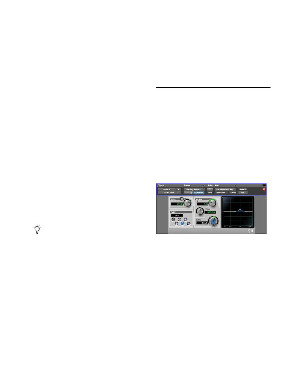
1-Band EQ
The 1-Band EQ has its own window, with six
selectable filter types for a single band of EQ.
1-Band EQ
Chapter 4: EQ III 15
Page 31

7-Band EQ
The 7-Band EQ has its own window, with up to
seven separate bands, each with it its own set of fi lter types.
Dragging in the Frequency Graph
Display
You can adjust the following by dragging the control points directly in the Frequency Graph display:
7 Band EQ
Adjusting EQ III Controls
In addition to dragging controls and typing control
values, there are other ways to adjust EQ III controls.
Inverting Filter Gain
(Peak EQ Bands Only)
Gain values can be inverted on any Peak EQ band
by Shift-clicking its control dot in the Frequency
Graph display, or its Gain knob in the plug-in window. This changes a gain boost to a cut (+9 to –9)
or a gain cut to a boost (–9 to +9). Gain values cannot be inverted on Notch, High Pass, Low Pass, or
shelving bands.
Frequency
Dragging a control point to the right increases the Frequency setting. Dragging a control
point to the left decreases the Frequency setting.
Gain
Dragging a control point up increases the
Gain setting. Dragging a control point down decreases the Gain setting.
Q
Control-dragging (Mac) or Start-dragging (Windows) a control point up decreases the Q setting.
Control-dragging (Mac) or Start-dragging (Windows) a control point down increases the Q setting.
Dragging a control point in the Frequency Graph
display
Chapter 4: EQ III 16
Page 32

Using EQ III in Band-Pass Mode
You can temporarily set any EQ III control to
Band-Pass monitoring mode. Band-Pass mode cuts
monitoring frequencies above and below the Frequency setting, leaving a narrow band of mid-range
frequencies. It is especially useful for adjusting
limited bandwidth in order to solo and fine-tune
each individual filter before reverting the control to
notch filter or peaking filter type operations.
Band-Pass mode does not affect EQ III Gain
controls.
When monitoring in Band-Pass mode, the Frequency and Q controls function differently.
Frequency
Sets the frequency above and below
which other frequencies are cut off, leaving a narrow band of mid-range frequencies.
Q
Sets the width of the narrow band of mid-range
frequencies centered around the Frequency setting .
To switch an EQ III control out of Band-Pass mode:
Release Control+Shift (Mac) or Start+Shift
(Windows).
To switch an EQ III control to Band-Pass mode:
Hold Control+Shift (Mac) or Start+Shift (Win-
dows), and drag any rotary control or control
point horizontally or vertically.
EQ III interactive graph displaying Band-Pass mode
Controlling EQ III from a Control
Surface
EQ III can be controlled from any supported control surface, including EUCON-compatible control
surfaces, D-Control, D-Command, C|24, and 003.
Refer to the guide that came with the control surface for details.
Chapter 4: EQ III 17
Page 33

EQ III I/O Controls
Input
Output Gain
Input and Output Meters
Gain
Input
Polarity
Clip
Indicators
Control
Control
Control
Certain Input and Output controls are found on all
EQ III configurations, except where noted otherwise.
I/O controls and meters for 7-Band EQ (top) and
1-Band EQ (bottom)
Input Gain Control
The Input Gain control sets the input gain of the
plug-in before EQ processing, letting you make up
gain or prevent clipping at the plug-in input stage.
Input Polarity Control
The Input Polarity button inverts the polarity of the
input signal to help compensate for phase anomalies occurring in multi-microphone environments,
or because of mis-wired balanced connections.
Input and Output Meters
(7-Band EQ Only)
The plasma-style Input and Output meters show
peak signal levels before and after EQ processing,
and indicate them as follows:
Green
Indicates nominal levels
Yellow
Indicates pre-clipping levels, starting at
–6 dB below full scale
Red
Indicates full scale levels (clipping)
When using the stereo version of EQ III, the Input
and Output meters display the sum of the left and
right channels.
The Clip indicators at the far right of each mete r indicate clipping at the input or output stage of the
plug-in. Clip indicators can be cleared by clicking
the indicator.
Output Gain Control
(7-Band EQ Only)
The Output Gain control sets the output gain after
EQ processing, letting you make up gain or prevent
clipping on the channel where the plug-in is being
used.
Chapter 4: EQ III 18
Page 34

EQ III EQ Band Controls
Individual EQ bands on each EQ III configuration
have a combination of controls.
EQ Type Selector
On the 1-Band EQ, the EQ Type selector lets you
choose any one of six available filter types:
High Pass, Notch, High Shelf, Low Shelf, Peak,
and Low Pass.
On the 7-Band EQ, the HPF, LPF, LF, and HF sections have EQ Type selectors to toggle between the
two available filter types in each section.
Band Enable Button
(7-Band EQ Only)
The Band Enable button on each EQ band toggles
the corresponding band in and out of circuit. When
a Band Enable button is highlighted, the band is in
circuit. When a Band Enable button is dark gray,
the band is bypassed and available for activation.
Band Enable button
Band Gain Control
Each Peak and Shelf EQ band has a Gain control
for boosting or cutting the corresponding frequencies. Gain controls are not used on High Pass,
Low Pass, or Notch filters.
EQ Type Selectors (7-Band EQ)
Band Gain control
Chapter 4: EQ III 19
Page 35

Frequency Control
Frequency
response
curve
Control dot
Frequency Graph
display
EQ Type
selector
Gain, Freq and
Input Level and
Polarity controls
Q controls
Each EQ band has a Frequency control that sets the
center frequency (Peak, Shelf and Notch EQs) or
the cutoff frequency (High Pass and Low Pass filters) for that band.
Frequency control
Q Control
Peak and Notch
control changes the width of the EQ band. Higher
Q values represent narrower bandwidths. Lower Q
values represent wider bandwidths.
Shelf
On Shelf bands, the Q control changes the Q
of the shelving filter. Higher Q values represent
steeper shelving curves. Lower Q values represent
broader shelving curves.
On Peak and Notch bands, the Q
1-Band EQ III
The Frequency Graph display in the 1-Band EQ
shows a control dot that indicates the center frequency (Peak, Shelf and Notch Filters) or the cutoff
frequency (High Pass and Low Pass filters) for the
currently selected filter type.
Frequency Graph display
Band Pass
On High Pass and Low Pass bands, the
Q control lets you select from any of the following
Slope values: 6 dB, 12 dB, 18 dB, or 24 dB per
octave.
1-Band EQ
The 1-Band EQ may be set to any one of six EQ
types: High Pass, Notch, High Shelf, Low Shelf,
Peak, and Low Pass, by clicking the corresponding
icon in the EQ Type selector.
Q control
Chapter 4: EQ III 20
Page 36

Band Controls
Notch Filter
The individual EQ types have some combination of
the following controls, as noted below.
Control Value
Frequency Range (All) 20 Hz to 20 kHz
Frequency Default (All) 1 kHz
Q Range (Low/High Shelf) 0.1 to 2.0
Q Range (Peak/Notch) 0.1 to 10.0
Q Default (All) 1.0
Gain Range (Low/High Shelf) –12 dB to +12 dB
High Peak Gain Range –18 dB to +18 dB
1-Band EQ III Types
High Pass Filter
The High Pass filter attenuates all frequencies below the Frequency setting at the selected rate (6 dB,
12 dB, 18 dB, or 24 dB per octave) while letting all
frequencies above pass through. No gain control is
available for this filter type.
The Notch Filter attenuates a narrow band of frequencies centered around the Frequency setting.
No gain control is available for this EQ type. The
width of the attenuated band is determined by the Q
setting.
1-Band EQ set to Notch Filter
High Shelf EQ
The High Shelf EQ boosts or cuts frequencies at
and above the Frequency setting. The amount of
boost or cut is determined by the Gain setting. The
Q setting determines the shape of the shelving
curve.
1-Band EQ set to High Shelf EQ
1-Band EQ set to High Pass Filter
Chapter 4: EQ III 21
Page 37

Low Shelf EQ
Low Pass Filter
The Low Shelf EQ boosts or cuts frequencies at and
below the Frequency setting. The amount of boost
or cut is determined by the Gain setting. The Q setting determines the shape of the shelving curve.
1-Band EQ set to Low Shelf EQ
Peak EQ
The Peak EQ boosts or cuts a band of frequencies
centered around the Frequency setting. The width
of the affected band is determined by the Q setting.
The Low Pass filter attenuates all frequencies
above the cutoff frequency setting at the selected
rate (6 dB, 12 dB, 18 dB, or 24 dB per octave)
while letting all frequencies below pass through.
No gain control is available for this filter type.
1-Band EQ set to Low Pass Filter
1-Band EQ set to Peak EQ
Chapter 4: EQ III 22
Page 38

7-Band EQ III
High Pass/
Low Pass/
Low
Shelf/Peak
Mid
Peak
High
Shelf/Peak
Low Mid
Peak
High Mid
Peak
Input/Output Level meters
Frequency Graph
Display
Input/Output Level
and
Polarity controls
Low Notch
High Notch
The 7-Band EQ has the following available bands: High Pass/Low Notch, Low Pass/High Notch,
Low Shelf/Low Peak, Low Mid Peak, Mid Peak, High Mid Peak, and High Shelf/High Peak.
All seven bands are available for simultaneous use. In the factory default setting, the High Pass/Low Notch
and Low Pass/High Notch bands are out of circuit, the Low Shelf and High Shelf bands are selected and in
circuit, and the Low Mid Peak, Mid Peak, High Mid Peak bands are in circuit.
7-Band EQ
Chapter 4: EQ III 23
Page 39

7-Band EQ III High Pass/Low
High Pass Filter
button
Frequency
control
Slope
control
Frequency
controlQcontrol
Band
Enable
button
Low Notch EQ
button
Band
Enable
button
Low Pass Filter
button
Frequency
control
Slope
control
Frequency
controlQcontrol
Band
Enable
button
High Notch EQ
button
Band
Enable
button
Notch
7-Band EQ III Low Pass/High
Notch
The High Pass/Notch band is switchable between
high pass filter and notch EQ functions. By default,
this band is set to High Pass Filter.
High Pass Filter
Attenuates all frequencies below
the Frequency setting at the selected slope while
letting all frequencies above pass through.
Low Notch EQ
Attenuates a narrow band of frequencies centered around the Frequency setting.
The width of the attenuated band is determined by
the Q setting.
The Low Pass/Notch band is switchable between
low pass filter and notch EQ functions. By default,
this band is set to Low Pass Filter.
Low Pass Filter
Attenuates all frequencies above
the Frequency setting at the selected slope while
letting all frequencies below pass through.
High Notch EQ
Attenuates a narrow band of frequencies centered around the Frequency setting.
The width of the attenuated band is determined by
the Q setting.
High Pass filter (left) and Low Notch EQ (right)
The High Pass and Low Notch EQ controls and
their corresponding graph elements are displayed
on-screen in gray. The following control values are
available:
Control Value
Frequency Range 20 Hz to 8 kHz
Frequency Default 20 Hz
HPF Slope Values 6, 12, 18, or 24 dB/oct
Low Notch Q Range 0.1 to 10.0
Low Notch Q Default 1.0
Chapter 4: EQ III 24
Low Pass filter (left) and High Notch EQ (right)
The Low Pass and High Notch EQ controls and
their corresponding graph elements are displayed
on-screen in gray. The following control values are
available:
Control Value
Frequency Range 120 Hz to 20 kHz
Frequency Default 20 kHz
HPF Slope Values 6, 12, 18, or 24 dB/oct
High Notch Q Range 0.1 to 10.0
High Notch Q Default 1.0
Page 40

7-Band EQ III Low Shelf/Low
Low Shelf EQ
button
Frequency
control
Band
Enable
button
Gain
control
Q
control
Low Peak EQ
button
Frequency
control
Band
Enable
button
Gain
control
Q
control
Frequency
control
Band
Enable
button
Gain
control
Q
control
Peak
The Low Shelf/Peak band is switchable between
low shelf EQ and low peak EQ functions. By default, this band is set to Low Shelf.
Low Shelf EQ
low the Frequency setting. The amount of boost or
cut is determined by the Gain setting. The Q setting
determines the shape of the shelving curve.
Low Peak EQ
centered around the Frequency setting. The width
of the affected band is determined by the Q setting.
Boosts or cuts frequencies at and be-
Boosts or cuts a band of frequencies
The Low Shelf and Low Peak Gain controls and
their corresponding graph elements are displayed
on-screen in red. The following control values are
available:
Control Value
Frequency Range 20 Hz to 500 Hz
Frequency Default 100 Hz
Low Shelf Q Range 0.1 to 2.0
Low Peak Q Range 0.1 to 10.0
Q Default 1.0
Low Shelf Gain Range –12 dB to +12 dB
Low Peak Gain Range –18 dB to +18 dB
7-Band EQ III Low Mid Peak
The Low Mid Peak band boosts or cuts frequencies
centered around the Frequency setting. The width
of the band is determined by the Q setting.
Low Shelf EQ (left) and Low Peak EQ (right)
Chapter 4: EQ III 25
Low Mid Peak EQ
The Low Mid Gain control and its corresponding
graph elements are displayed on-screen in brown.
Page 41

The following control values are available:
Frequency
control
Band
Enable
button
Gain
control
Q
control
Frequency
control
Band
Enable
button
Gain
control
Q
control
7-Band EQ III High Mid Peak
Control Value
Frequency Range 40 Hz to 1 kHz
Frequency Default 200 Hz
Low Mid Peak Q Range 0.1 to 10.0
Low Mid Peak Q Default 1.0
Low Mid Peak Gain Range –18 dB to +18 dB
7-Band EQ III Mid Peak
The Mid Peak band boosts or cuts frequencies centered around the Frequency setting. The width of
the band is determined by the Q setting.
The High Mid Peak band boosts or cuts frequencies
centered around the Frequency setting. The width
of the band is determined by the Q setting.
High Mid Peak EQ
The High Mid Gain control and its corresponding
graph elements are displayed on-screen in green.
The following control values are available:
Control Value
Frequency Range 200 Hz to 18 kHz
Frequency Default 2 kHz
Mid Peak Q Range 0.1 to 10.0
Mid Peak EQ
The Mid Gain control and its corresponding graph
Mid Peak Q Default 1.0
Mid Peak Gain Range –18 dB to +18 dB
elements are displayed on-screen in yellow. The
following control values are available:
Control Value
Frequency Range 125 Hz to 8 kHz
Frequency Default 1 kHz
Mid Peak Q Range 0.1 to 10.0
Mid Peak Q Default 1.0
Mid Peak Gain Range –18 dB to +18 dB
Chapter 4: EQ III 26
Page 42
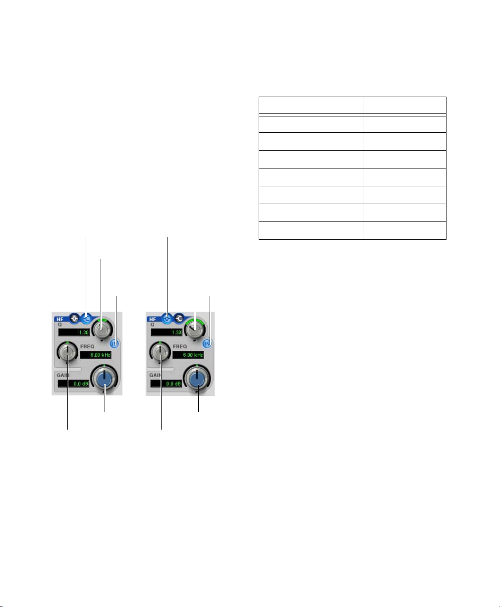
7-Band EQ III High Shelf/High
High Shelf EQ
button
Frequency
control
Band
Enable
button
Gain
control
Q
control
High Peak EQ
button
Frequency
control
Band
Enable
button
Gain
control
Q
control
Peak
The High Shelf/Peak band is switchable between
high shelf EQ and high peak EQ functions. By default, this band is set to High Shelf.
High Shelf EQ
above the Frequency setting. The amount of boost
or cut is determined by the Gain setting. The Q setting determines the shape of the shelving curve.
High Peak EQ
centered around the Frequency setting. The width
of the affected band is determined by the Q setting.
Boosts or cuts frequencies at and
Boosts or cuts a band of frequencies
The High Shelf and High Peak Gain controls and
their corresponding graph elements are displayed
on-screen in blue. The following control values are
available:
Control Value
Frequency Range 1.8 kHz to 20 kHz
Frequency Default 6 kHz
High Shelf Q Range 0.1 to 2.0
High Peak Q Range 0.1 to 10.0
Q Default 1.0
High Shelf Gain Range –12 dB to +12 dB
High Peak Gain Range –18 dB to +18 dB
High Shelf EQ (left) and High Peak EQ (right)
Chapter 4: EQ III 27
Page 43
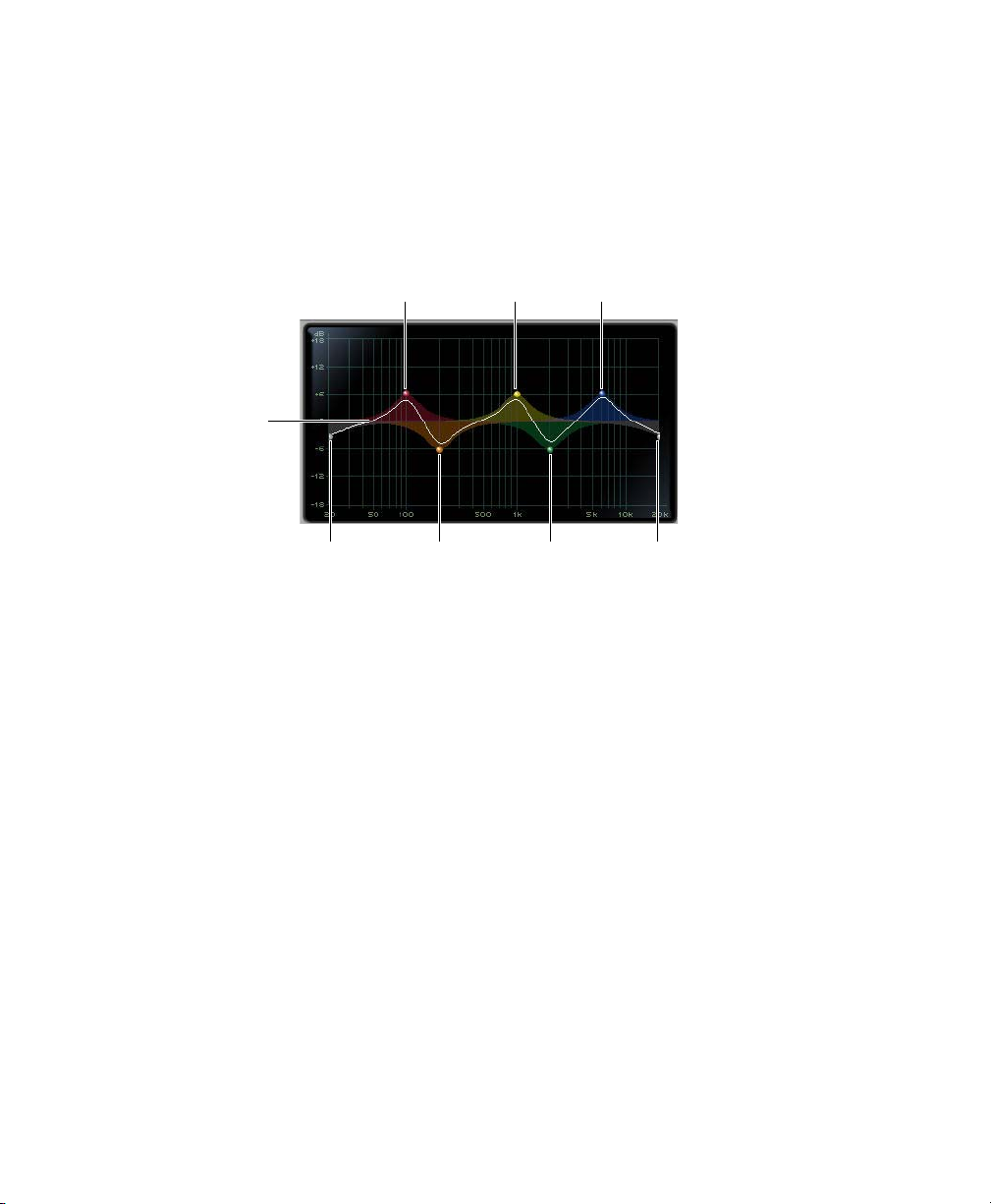
Frequency Graph Display
High Pass
control dot
Low Mid
control dot
High Mid
control dot
Low Pass
control dot
(gray) (brown) (green) (gray)
Low
control dot
(red)
Mid
control dot
(yellow)
High
control dot
(blue)
Frequency
response
curve
(7-Band EQ Only)
The Frequency Graph display in the 7-Band EQ shows a color-coded control dot that corresponds to the
color of the Gain control for each band. The filter shape of each band is similarly color-coded. The white frequency response curve shows the contribution of each of the enabled filters to the overall EQ curve.
Frequency Graph display for the 7-Band EQ
Chapter 4: EQ III 28
Page 44

Chapter 5: Eleven Effects Graphic EQ
Graphic EQ
Graphic EQ is useful for simple frequency sculpting. Use Graphic EQ before other effects, such as
Distortion, to shape the sonic results of additional
processing.
Graphic EQ is available as a Mono or Stereo
plug-in.
Frequency Band Gain
Graphic EQ provides gain controls for five frequency bands:
3.25 kHz.
The
370 Hz, 800 Hz, and 2kHz bands can be
boosted by up to 18 dB and attenuated down by as
much as –18 dB.
100 Hz and 3.25 kHz bands can be boosted by
The
up to 12 dB and attenuated down by as much as
–12 dB.
Output Gain
The Output gain control lets you boost the plug-in
output by as much as +6 dB or attenuate the output
by as much as – 20 dB.
100 Hz, 370 Hz, 800 Hz, 2kHz, and
Chapter 5: Eleven Effects Graphic EQ 29
Page 45

Chapter 6: Focusrite D2
Focusrite D2 is a high-quality digital equalizer
plug-in for Pro Tools. Developed in cooperation
with Focusrite, the D2 is based on the acclaimed
Red Range 2
It provides up to six simultaneous bands of EQ, including: high-pass, low-shelf, low-mid peak, highmid peak, high-shelf, and low-pass filters. D2 includes a highly accurate Cartesian graph that displays EQ curves in real-time as EQ controls are adjusted.
D2 is available in DSP, Native, and AudioSuite
formats.
D2 supports 44.1 kHz, 48 kHz, 88.2 kHz, 96 kHz,
176.4 kHz, and 192 kHz sample rates.
D2 operates as a mono, multi-mono, or stereo
plug-in.
™
dual EQ, designed by Rupert Neve.
D2 Configurations
There are three configurations of the Focusrite D2
plug-in.
1–2 Band EQ
D2 1-2 Band can use up to two filters simultaneously, depending on which you enable. The highpass, low-shelf, and low-pass filters each utilize the
entire module and cannot be used in combination
with another filter. The low-mid peak, high-mid
peak, or high-shelf filters can be used in combination with each other (up to two bands total).
4-Band EQ
D2 4-Band can use up to four filters simultaneously. Any combination of filters can be engaged,
up to a total of four bands.
6-Band EQ
D2 6-Band can use up to six filters simultaneously.
Any combination of filters can be engaged, up to a
total of six bands. By default, the low-pass and
high-pass filters are in Bypass mode when the
6-Band EQ is first opened.
Focusrite D2
Focusrite D2 supports EQ Curve in Pro Tools
2018.1 and later.
Chapter 6: Focusrite D2 30
Page 46

D2 Controls
Input Level
Input Level allows you to attenuate signal input
level to the D2. The range of this control is from
–18 dB to +12 dB.
When you use D2 in stereo, each channel has its
own separate Input Level knob. To adjust input levels for both channels simultaneously, select the
Link button, then drag either knob.
input Level
Output Level
Output Level allows you to adjust the overall output gain. The range of this control is from –18 dB
to +12 dB.
Meters
The D2 high-resolution plasma-style meters indicate signal levels and detect clipping at the input,
algorithm, or output stage. When D2 is used in stereo, two meters appear, one for each channel.
A Clip Indicator is located above each meter. It indicates clipping by increasing its brightness as successive samples are clipped. Click the Clip Indicator to clear it. Option-clicking (Mac) or Altclicking (Windows) clears both channels when D2
is used in stereo.
Meters (Stereo mode)
The following metering indications are used:
Output Level
When you use the D2 plug-in in stereo, each channel has its own separate output level knob. To adjust output levels for both channels simultaneously,
select the Link button.
Chapter 6: Focusrite D2 31
• Green = nominal levels
• Yellow = pre-clipping at –6 dB below full scale
signal
• Red = full scale signal (clipping)
Page 47
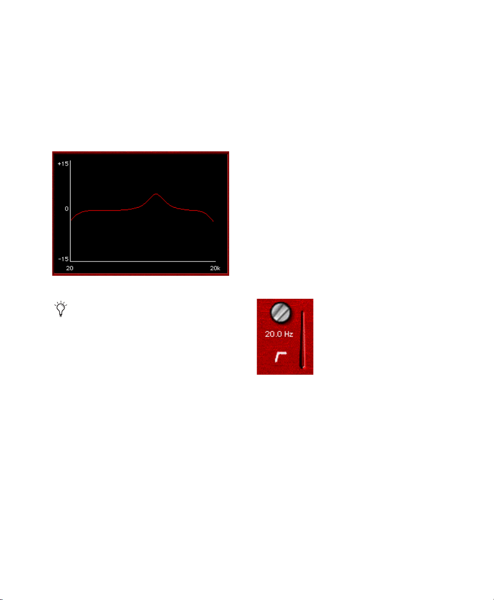
Frequency Display
EQ Filter Controls
The frequency display is a visual representation of
the current EQ settings. As you adjust the controls
of any currently active filter, the display plots the
changes to the EQ curve in real-time. If you are using D2 in stereo, the frequency display shows the
EQ curve for the right channel in red and the left
channel in blue.
Cartesian Graph
To reset all D2 controls to their default
settings, Option-click (Mac) or Alt-click
(Windows) the frequency display. To
reset controls for both channels when in
Stereo mode, Option-Shift-click (Mac) or
Alt-Shift-click (Windows) the frequency
display.
Each of the six different EQ filters has its own controls and its own icon. The icons act as three-state
switches for enabling, disabling, or bypassing the
specific filter. The current state of a filter is indicated by its color:
• White = enabled. In this state the filter is active,
audible, and using available DSP resources.
• Black = disabled. In this state the filter is not using any DSP resources and has no effect on audio.
• Gray = bypassed. In this state the filter is not active, but is still using available DSP resources.
The effect of the filter is not audible.
High-Pass Filter
The 18 dB/octave High-Pass Filter provides a rotary control for adjusting the corner (cutoff) frequency, variable from 20 Hz to 6.4 kHz.
High-Pass Filter
Chapter 6: Focusrite D2 32
Page 48

Low-Shelf Filter
High-Mid Peak Filter
The Low-Shelf Filter provides two rotary controls:
The upper rotary control adjusts the corner frequency, variable from 33 Hz to 460 Hz. The lower
rotary control adjusts the filter’s amplitude gain or
attenuation. Amplitude range is ±15 dB from unity.
Low-Shelf Filter
Low-Mid Peak Filter
The Low-Mid Peak Filter provides three rotary
controls. The upper rotary control adjusts the center
frequency, variable from 33 Hz to 6.4 kHz. The
lower left rotary control adjusts the filter’s amplitude gain or attenuation. Amplitude range is
±15 dB from unity (utilizing a reciprocal curve for
both gain and attenuation). The lower right rotary
control adjusts filter “Q” which is variable from 0.7
to 4.0.
The High-Mid Peak Filter provides three rotary
controls. The upper rotary control adjusts the center
frequency, variable from 120 Hz to 18 kHz. The
lower left rotary control adjusts the filter’s amplitude gain or attenuation. Amplitude range is
±15 dB from unity (utilizing a reciprocal curve for
both gain and attenuation). The lower right rotary
control adjusts filter “Q” which is variable from 0.7
to 4.0.
High-Mid Peak Filter
High-Shelf Filter
The High-Shelf Filter provides two rotary controls:
The upper rotary control adjusts the corner frequency, variable from 3.3 kHz to 18 kHz. The
lower rotary control adjusts the filter’s amplitude
gain or attenuation. Amplitude range is ±15 dB
from unity.
Low-Mid Peak Filter
High-Shelf Filter
Chapter 6: Focusrite D2 33
Page 49
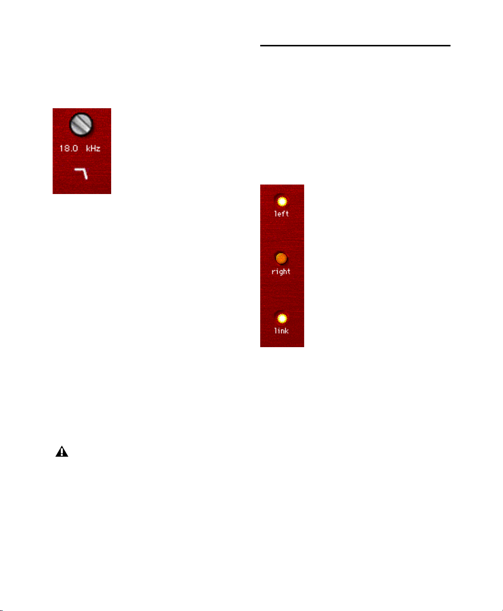
Low-Pass Filter
The 18 dB/octave Low-Pass Filter provides a rotary control for adjusting the filter’s cutoff frequency, variable from 100 Hz to 18 kHz.
Low-Pass Filter
Enabling, Disabling and
Bypassing EQ Filters
You can enable, disable, or bypass specific EQ filters by clicking them.
To disable a filter:
Control-click (Mac) or Start-click (Windows)
the EQ Filter icon. When disabled, the icon is
black.
Using D2 in Stereo
Because Focusrite D2 has a single set of Filter control knobs, when it is used in stereo, you must select
which channel, left or right, you want to edit.
Left Channel and Right Channel
Buttons
The Left Channel and Right Channel buttons are
used to select which controls are active.
To re-enable a filter:
Click the EQ filter icon. When enabled, the icon
Left Channel, Right Channel, and Link buttons
is white.
To bypass a filter:
Click the EQ filter icon a second time. When by-
passed, the icon is gray.
If you are using all available bands of the 1–2
Band or 4–Band EQ and want to change filter types, you must disable one filter before
you can enable a different one.
Chapter 6: Focusrite D2 34
Page 50

Link Button
The Link button lets you adjust controls for both
channels simultaneously. By default, Link mode is
enabled so that you can maintain parity between
channels.
You can also use Link mode to help you maintain a
relative offset between control settings on the two
channels.
To maintain an offset between channels:
1 Deselect the Link button.
2 Select a channel button, left or right, and adjust
the controls for that channel.
3 Select Link mode and adjust the same controls
for the opposite channel. D2 will maintain the
relative offset between the two channels.
To copy the control settings of the active
channel to the opposite channel, Option-click
(Mac) or Alt-click (Windows) while linking
channels.
Chapter 6: Focusrite D2 35
Page 51

Chapter 7: JOEMEEK VC5 Meequalizer
The JOEMEEK VC5 Meequalizer is an EQ plug-in
that is available in DSP, Native, and AudioSuite
formats.
VC5 supports 44.1 kHz, 48 kHz, 88.2 kHz,
96 kHz, 176.4 kHz, and 192 kHz sample rates.
VC5 operates as a mono, multi-mono, or stereo
plug-in.
JOEMEEK Meequalizer VC5 EQ
The VC5 offers simple controls with incredibly
warm, musical results. Among countless other
achievements, Joe Meek built custom gear to get
the sounds in his head onto tape. One device was a
treble and bass circuit with a sweepable mid control, built into a tiny tobacco tin. The Meequalizer
VC5 virtually recreates the exact circuitry used by
Joe Meek in this device.
JOEMEEK Meequalizer Controls
Operation of the Meequalizer is simple and to the
point.
Bass
The Bass control adjusts low frequencies
±11.
Mid and Mid Freq
allow you to adjust mid frequencies, from 500Hz to
3.5KHz, ±11.
Treble
The Treble control adjusts high frequencies
±11.
Gain
The Gain control allows you to adjust the out-
put level ±11.
The Mid and Mid Freq controls
VC5 supports EQ Curve in Pro Tools 2018.1
and later.
Chapter 7: JOEMEEK VC5 Meequalizer 36
Page 52

Chapter 8: Pultec Plug-Ins
The Pultec plug-ins are a set of EQ plug-ins that are
available in DSP, Native, and AudioSuite formats.
The following plug-ins are included:
• Pultec EQP-1A
• Pultec EQH-2
• Pultec MEQ-5
The Pultec plug-ins support 44.1 kHz, 48 kHz,
88.2 kHz, 96 kHz, 176.4 kHz, and 192 kHz sample
rates.
The Pultec plug-ins operate as mono, multi-mono,
or stereo plug-ins.
Pultec plug-ins support EQ Curve in Pro Tools
2018.1 and later.
Pultec EQP-1A
The Pultec EQP-1A provides smooth, sweet EQ
and an extremely high quality tube audio signal
path. Use it on individual tracks, critical vocals, or
even across a stereo mix for mastering applications.
Built in the early 1960s, the Pultec EQP-1A offers
gentle shelving program equalization on bass and
highs, and offers a variable bandwidth peak boost
control. A custom (and secret) filter network provides all its equalization functionality. Quality
transformers interface it to real-world studio equipment. A clean and well-designed tube amplifier
provides a fixed amount of make-up gain.
Pultec EQP-1A Controls
Low Frequency Section
using the Boost and Atten knobs and the Low Frequency switch, located at the left side of the unit.
All low-frequency equalization is a gentle shelving
type, 6 dB per octave.
High Frequency Boost Section
high frequencies using the Bandwidth and Boost
knobs and the High Frequency switch.
High Frequency Attenuate Section
quencies using the Atten knob and the Atten Sel
switch located at the right side of the plug-in.
Use caution, because the Sharp bandwidth setting
results in up to 10 dB higher output than Broad
bandwidth at maximum Boost, just like on the original. But don’t feel like you’re getting cheated.
Consider anything that encourages very careful and
infrequent use of peaky boosts to be a Very Good
Thing.
Adjust low frequencies
Boost mid and
Cut high fre-
Pultec EQP-1A
Chapter 8: Pultec Plug-Ins 37
Page 53

Pultec EQH-2
Pultec MEQ-5
The Pultec EQH-2 is a program equalizer similar to
the Pultec EQP-1A. It is designed to provide
smooth equalization across final mixes or individual tracks.
Pultec EQH-2
The Pultec EQH-2 offers three equalization sections: low frequency boost and attenuation, midrange boost only, and 10k attenuation. Like its
EQP-1A sibling, it features high-quality transformers and a tube gain stage. But unlike the EQP-1A,
the tube stage in the EQH-2 is a push-pull design.
As a result, the EQH-2 offers a beefier tone.
Pultec EQH-2 Controls
Low Frequency Section
using the top row of Boost and Atten knobs and the
CPS (cycles per second) switch. All low-frequency
equalization is a gentle shelving type, 6 dB per octave.
Adjust low frequencies
The Pultec MEQ-5 is the most unique equalizer in
the Pultec family. It is particularly useful on individual tracks during mixdown.
Pultec MEQ-5
Pultec MEQ-5 Controls
The Pultec MEQ-5 offers three equalization sections: low frequency boost, mid frequency boost,
and wide-range attenuation. Like all Pultecs, it features quality transformers and a tube gain stage.
Low Frequency Peak
300, 500, 700, 1000 Hz) using the upper left controls.
Mid Frequency Peak
2k, 3k, 4k, 5k) using the controls at the upper right.
Wide-Range Dip
trols on the bottom row.
Boost low frequencies (200,
Boost mid-frequencies (1.5k,
Cut frequencies using Dip con-
High Frequency Boost Section
Boost mid and
high frequencies using the KCS (kilocycles per
second) and Boost knobs on the second row.
High Frequency Attenuate Section
Cut high frequencies using the 10k Atten knob located at the
right side of the plug-in.
Chapter 8: Pultec Plug-Ins 38
Page 54

Pultec Tips and Tricks
“Q” and A
You may wonder why the Pultec EQP-1A has separate knobs for boost and cut. The short answer is
that they connect to different circuitry in the unit.
You can use the “extra” knob to your advantage.
Because the filters are not phase perfect, a Boost
setting of 3 and an Atten setting of 3 can make a
huge difference, even though a frequency plot
wouldn’t show much difference in tone. You’re
hearing the phase shift, not the tone shift.
Our ears are very sensitive to phase, and using the
two knobs together, you can adjust phase at the low
end while also making tonal adjustments.
On the high end, you can set Boost to 10k and Atten
to 10k, then adjust Boost and Atten simultaneously.
However, because Boost is a peak equalizer and
Atten is a shelving equalizer, the results are much
different, and you don’t get independent control of
phase.
Guitars
Have multiple guitars that sound like mush in the
mix? The Pultec MEQ-5 is a classic tool for achieving amazing guitar blends. Try boosting one guitar
and cutting another to achieve an octave of separation. For example, cut one guitar using 1.5
(1500 Hz) Dip, then boost the other using 3
(3000 Hz) Peak. View the matched pairs of presets
(such as Guitar 1A and 1B or 2A and 2B) for further examples of this technique.
“Q” and Boost
In the high frequency boost section, the Bandwidth
and Boost controls affect one another. This is different from modern equalizers, where adjusting Q
typically doesn’t affect the amount of equalization
applied.
Chapter 8: Pultec Plug-Ins 39
Page 55

Part 3: Dynamics Plug-Ins
Page 56

Chapter 9: BF-2A
BF-2A is a vintage-style compressor plug-in that is
available in DSP, Native, and AudioSuite formats.
BF-2A supports 44.1 kHz, 48 kHz, 88.2 kHz,
96 kHz, 176.4 kHz, and 192 kHz sample rates.
BF-2A operates as a mono, multi-mono, or stereo
plug-in.
BF-2A
Designed and manufactured in the early 1960s, the
LA-2A achieved wide acclaim for its smooth compression action and extremely high quality audio
signal path. The BF-2A has been meticulously
crafted to capture every nuance of the legendary
LA-2A tube studio compressor, providing the most
authentic vintage compression sound available.
Originally designed as a limiter for broadcast audio, a Comp/Limit switch was added to LA-2A
compressors after serial number 572. The subsequent addition of a Comp (Compress) setting made
the LA-2A even more popular for use in audio production. However, the switch was inconveniently
located on the back of the unit next to the terminal
strips and tube sockets in the original version. In
the BF-2A plug-in, the switch has been placed on
the front panel, where you can make better use of it.
The heart of the LA-2A is its patented T4B
Electro-Optical Attenuator, which provides the
compression action. The T4B consists of a photoconductive cell, which changes resistance when
light strikes it. It is attached to an electroluminescent panel, which produces light in response to
voltage. Audio (voltage) is applied to the light
source, and what happens as the audio converts to
light and back to voltage gives the LA-2A its
unique compression action (BF-2A preserves all
the subtle characteristics of this unique electronic
circuit). After compression, gain brings the signal
back to its original level. The LA-2A’s gain comes
from a tube amplifier, which imparts further character to the tone. In fact, it’s common to see engineers using the LA-2A simply as a line amp, without any compression applied to the signal.
One beautiful side effect of the LA-2A’s elegant
design is that it’s easy to hear the compression action. When the BF-2A’s two knobs are set properly,
you know you got it right.
Chapter 9: BF-2A 41
Page 57

BF-2A Controls
The Peak Reduction and Gain controls combine
with the Comp/Limit switch to determine the
amount and sound of the compression. The following controls and meters are provided:
Gain
Gain provides makeup gain to bring the signal
back after passing through peak reduction.
Peak Reduction
amount of signal entering the side-chain, which in
turn affects the amount of compression and the
threshold. The more Peak Reduction you dial in,
the more “squashed” the sound. Too little peak reduction and you will not hear any compression action; too much and the sound becomes muffled and
dead sounding.
Comp/Lim
compression ratio. The common setting for audio
production is Comp, which provides a maximum
compression ratio of approximately 3:1. In Limit
mode, the unit behaves more like a broadcast limiter, with a higher threshold and compression ratio
of approximately 12:1.
Meter
Both Gain Reduction and Output metering
are provided. The Meter knob operates as follows:
• When set to Gain Reduction, the meter needle
moves backward from 0 to show the amount of
compression being applied to the signal in dB.
• When set to Output, the needle indicates the out-
put level of the signal. The meter is calibrated
with 0 VU indicating –18 dBFS.
Peak Reduction controls the
The Comp/Limit switch affects the
Using the BF-2A Side-Chain Filter
The BF-2A provides an extra, a side-chain filter,
that does not have a control on the plug-in interface, but that can be accessed on-screen through
Pro Tools automation controls. In addition, the
side-chain filter can be adjusted directly from any
supported control surface.
This side-chain filter reproduces the effect of an adjustable resistor on the back panel of the LA-2A.
This control cuts the low frequencies from the sidechain, or control signal, that determines the amount
of gain reduction applied by the compressor.
By increasing the value of the side-chain filter, you
filter out frequencies below 250 Hz from the control signal, and decrease their effect on gain reduction.
A setting of zero means that the filter is not ap-
plied to the side chain signal.
A setting of 100 means that all frequencies be-
low 250 Hz are filtered out of the side chain signal.
To access the side-chain filter on-screen:
1 Click the Plug-In Automation button in the
Plug-In window to open the Automation Enable
window.
2 In the list of controls at the left, click to select
Side-Chain Filter and click
click a control in the list).
3 Click OK to close the plug-in automation win-
dow.
Add (or just double-
Chapter 9: BF-2A 42
Page 58

4 In the Edit window, do one of the following:
• Click the Track View selector and select Side-
Chain Filter from the BF-2A sub-menu.
• Reveal an Automation lane for the track, click
the Automation Type selector and select SideChain Filter from the BF-2A sub-menu.
5 Edit the breakpoint automation for the BF-2A
side-chain filter. Control range is from 0 (the default setting where no filtering is applied to the
side-chain) to 100% (maximum side-chain filtering).
To access the side-chain filter from a control
surface:
1 Focus the BF-2A plug-in on your control sur-
face.
2 Adjust the encoder or fader current targeting the
Side-Chain Filter control.
For more information on plug-in automation,
see the Pro Tools Reference Guide
BF-2A Tips and Tricks
AudioSuite Processing
When using the AudioSuite version of the BF-2A,
be sure to select an auxillary side-chain input (normally the track you’re processing). The default is
“None” and if you leave it set like this, there is
nothing feeding the detector and you will not hear
any compression action.
Line Amp
Turn the Peak Reduction knob full counterclockwise (off) and use the Gain control to increase the
signal level. Although the BF-2A does not compress the sound with these settings, it still adds its
unique character to the tone.
Feed the BF-2A into the BF76
Or vice versa. Glynn Johns (who has worked with
the Stones, the Who, and others) popularized the
early ‘70s British trick of combining a slower compressor with a faster one. The effect can produce
very interesting sounds! Try applying Peak Reduction using the BF-2A, then squash the missed attacks using the faster BF76.
Chapter 9: BF-2A 43
Page 59

Chapter 10: BF-3A
BF-3A is a vintage-style compressor plug-in that is
available in DSP, Native, and AudioSuite formats.
BF-3A supports 44.1 kHz, 48 kHz, 88.2 kHz,
96 kHz, 176.4 kHz, and 192 kHz sample rates.
BF-3A operates as a mono, multi-mono, or stereo
plug-in.
BF-3A
BF-3A is based on the classic LA-3A that adds a
smoothness and sonic texture that makes sounds
jump right out of the mix. Designed and manufactured in the late 1960s, the original LA-3A shares
many components in common with the LA-2A
compressor. Just like the LA-2A, the heart of the
LA-3A is the T4B Electro-Optical Attenuator. This
is a device that converts audio to light and back and
is largely responsible for the compression character
of the unit.
While the LA-2A’s gain comes from a tube amplifier, the LA-3A's gain comes from a solid-state
(transistor) amplifier. This gives the LA-3A a solid
midrange and more aggressive tone. Other subtle
modifications change the behavior of the T4B,
causing it to respond differently—particularly in
response to percussive material.
The LA-3A is famous for its unique sonic imprint
on guitar, piano, vocals and drums. Because it's so
easy to control, you'll be getting classic tones in no
time with the BF-3A.
BF-3A Controls
The Peak Reduction and Output Gain controls
combine with the Comp/Limit switch to determine
the amount and sound of the compression. The following controls and meters are provided:
Peak Reduction
amount of signal entering the side-chain. The more
Peak Reduction you dial in, the more “squashed”
and compressed the sound will be. Too little peak
reduction and you won’t hear any compression action; too much and the sound becomes muffled and
dead sounding.
Output Gain
make the signal louder after passing through the
peak reduction.
Peak Reduction controls the
Output Gain provides makeup gain to
Chapter 10: BF-3A 44
Page 60

Comp/Lim
compression ratio. The common setting for audio
production is Comp, which provides a maximum
compression ratio of approximately 3:1. In Limit
mode, the unit behaves more like a broadcast limiter, with a higher threshold and compression ratio
of approximately 15:1.
Meter
are provided. The Meter knob operates as follows:
• When set to Gain Reduction, the meter needle
moves backward from 0 to show the amount of
compression being applied to the signal in dB.
• When set to Output, the needle indicates the out-
put level of the signal. The meter is calibrated
with 0 VU indicating –18 dBFS.
The Comp/Limit switch affects the
Both Gain Reduction and Output metering
BF-3A Tips and Tricks
AudioSuite Processing
When using the AudioSuite version of the BF-3A,
be sure to select an auxillary side-chain input (normally the track you are processing). The default is
“None” and if you leave it set like this, there is
nothing feeding the detector and you will not hear
any compression action.
Line Amp
Turn the Peak Reduction knob full counterclockwise (off) and use the Gain control to increase the
signal level. Although the BF-3A does not compress the sound with these settings, it still adds its
unique character to the tone.
Chapter 10: BF-3A 45
Page 61

Chapter 11: BF76
BF76 is a vintage-style compressor plug-in that is
available in DSP, Native, and AudioSuite formats.
BF76 supports 44.1 kHz, 48 kHz, 88.2 kHz,
96 kHz, 176.4 kHz, and 192 kHz sample rates.
BF76 operates as a mono, multi-mono, or stereo
plug-in.
BF76
Modeled after the solid-state 1176 studio compressor, BF76 preserves every sonic subtlety of this
classic piece of studio gear.
The 1176 Compressor, originally introduced in the
late 1970s, uses a FET (field-effect transistor). The
1176 also uses solid state amplification. The 1176
still provides an extremely high quality audio signal path, but because of these internal differences,
offers a much different compression sound than
other compressors.
Four selectable compression ratios are provided,
along with controls allowing variable attack and release times.
BF76 Controls
BF76 provides the following controls:
Input
The Input control sets the input signal level to
the compressor, which, in the 1176 design, determines both the threshold and amount of peak reduction.
Output
The Output control sets output level. Use it
to bring the signal back to unity after applying gain
reduction.
Attack and Release
trols set the attack and release times of the compressor. Full counterclockwise is slowest, and full
clockwise is fastest. Attack times vary between 0.4
milliseconds to 5.7 milliseconds. Release times
vary between 60 and 1,100 milliseconds.
Ratio
The Ratio Push switches select the compres-
sion ratio from 4:1 to 20:1.
Meter
The Meter Push switches affect the meter-
ing.
• GR shows the amount of gain reduction.
• –18 and –24 show the output level (calibrated so
that 0VU indicates –18dB FS and –24dB FS respectively).
• The “Off” switch turns off the meter.
The Attack and Release con-
Chapter 11: BF76 46
Page 62

BF76 Tips and Tricks
Selecting Proper Attack and
Release Times
AudioSuite Processing
When using the AudioSuite version of BF76, be
sure to select a side-chain input (normally the track
you are processing). The default is “None” and if
you leave it set like this, there’s nothing feeding the
detector and you won’t hear any compression action.
Unexpected Visit from A&R
Weevil Yields Instant Hit Mix
A favorite feature on one megabuck mixing console is its stereo bus compressor. With the flick of a
switch, a punchy 8:1 compressor grabs the current
mix producing “instant radio hit.” It’s also a handy
way to make quick headphone submixes when
tracking overdubs.
Give the Kids What They Want
Shift-click one of the Ratio Push switches to enable
the “All Buttons In” mode. The compression ratio
is still only 20:1, but the knee changes drastically
and the compressor starts (mis)behaving a little bit
like an expander—watch the meter for details. Hey,
try it—sometimes it even sounds good.
As on the original unit, setting either the attack or
release time too fast generates signal distortion.
Again, this may or may not be a effect. A good
starting point for attack and release is “6” and “3”
(the defaults), and you can adjust as follows:
When compressing, use the slowest attack you can
that preserves a dynamic range. Faster attacks remove the “punch” from the performance; slower
attacks inhibit the compression you need to smooth
things out.
When limiting, use the fastest attack time you can
before you start to hear signal distortion in the low
end. With BF76, the attack time ranges from “incredibly fast” to “really damn fast” by modern standards. It can be hard to hear the difference.
Release times are more critical with BF76. To set
release times, listen for loud attacks and what happens immediately after the peaks. Set the release
time fast enough that you don’t hear unnatural dynamic changes, but slow enough that you don’t
hear unnecessary pumping between two loud passages in rapid succession.
Chapter 11: BF76 47
Page 63

Chapter 12: Channel Strip
Avid Channel Strip is available in DSP , Native, and
AudioSuite formats. Channel Strip provides EQ,
Dynamics, Filter, and Gain effects. Channel Strip
processing algorithms are based on the Euphonix
System 5 console channel strip effects.
Channel Strip supports 44.1 kHz, 48 kHz,
88.2 kHz, 96 kHz, 176.4 kHz, and 192 kHz sample
rates.
Channel Strip supports mono, stereo, and greaterthan-stereo multichannel formats up to 7.1.
Greater-than-stereo formats are only
available with Pro Tools Ultimate.
In addition to standard knob and fader controls,
Channel Strip also provides a graph to track the
gain transfer curve for the Expander/Gate, Compressor/Limiter, and Side Chain effects, and a Frequency Graph display that shows the response
curve for the current EQ setting on a two-dimensional graph of frequency and gain. The frequency
graph display also lets you modify frequency, gain,
and Q settings for individual EQ bands by dragging
their corresponding points in the graph.
Channel Strip provides different sections for signal
metering and gain adjustment, signal path ordering,
dynamics processing, and equalization and filtering.
Channel Strip, Compressor/Limiter tab shown
Chapter 12: Channel Strip 48
Page 64

Channel Strip Sections and Panes
The Channel Strip plug-in window is organized in
several sections: Input, FX Chain, Output, Dynamics, and EQ/Filters. The Dynamics and EQ/Filters
sections can be independently shown or hidden.
This lets you access controls or free up screen
space, depending on your needs.
When showing the Dynamics or EQ/Filters sections, several tabbed panes of controls are available
for each section. You can click a tab to show the
controls for that tabbed pane. For Expand/Gate and
Compressor/Limiter, and also for the For the EQ
and Filter effects, clicking the corresponding control point on the graph display automatically shows
the tab for Expander/Gate or the Compressor/Limiter, or the corresponding EQ band or Filter.
Showing or Hiding the Dynamics
and EQ/Filters Sections
You can independently show or hide the Dynamics
and EX/Filters sections of the Channel Strip plugin to use less screen space. These sections are
shown by default.
To hide (or show) the Dynamics or EQ/Filters
section of the plug-in window:
Click the Show/Hide triangle to the left of the
section you want to show or hide.
Channel Strip, Dynamics section hidden
Chapter 12: Channel Strip 49
Page 65

Disabling or Enabling Channel
Strip Effects
You can independently disable effects in the Dynamics and EQ/Filters sections of the Channel
Strip plug-in. For example, you may want to apply
Comp/Limit processing to the signal, but not
Exp/Gate; or, you may want to only apply only a
high pass filter.
Dynamics section, Exp/Gate disabled
To enable effects in the Dynamics or EQ/Filters
section:
Click the Enable/Disable button for the effect
you want to enable so that it is highlighted.
To disable effects in the Dynamics or EQ/Filters
section:
Click the Enable/Disable button for the effect
you want to disable so that it is not highlighted.
Listen Mode
The Side Chain tab in the Dynamics section, and
the EQ and Filter tabs in the EQ/Filter section provide a Listen button.
When enabled for the Side Chain, Listen mode
lets you hear the input signal that feeds the dynamic
section. This can be either the external key input or
the internal side chain (including the applied filter).
When enabled for any of the EQ bands, Listen
solos the corresponding EQ band and (temporarily)
inverts the EQ Type so that you can tune the Frequency and the Q for that EQ band.
When enabled for either of the Filter effects,
Listen solos the enabled Filter band and inverts the
Filter. This allows you to hear only hear the portion
of the audio signal that is being removed by the
filter.
To enable (or disable) Listen on the Side Chain
effect, EQ band, or a Filter effect:
Click the Listen button for the Dynamics or
EQ/Filter tab you want so that it is highlighted.
Click it again so that it is not highlighted to disable it.
Channel Strip, Chain Listen mode enabled
Control-Shift-click (Mac) or Start-Shift-click
(Windows) and hold an EQ or Filter control
point in the Frequency Graph to temporarily
switch to Listen mode for that EQ band or
Filter effect.
Chapter 12: Channel Strip 50
Page 66

Channel Strip Input Section
The Input section provides input metering, and
controls for trimming the input signal and inverting
its phase. It can also be toggled to show post-processing gain reduction meters.
Input Meters
The Input meters show peak signal levels before
processing:
Dark Blue
–12 dB.
Indicates nominal levels from –INF to
Input section (5.1 channel format shown)
Input Trim Control
The Input Trim control sets the input gain of the
plug-in before EQ processing, letting you make up
gain or prevent clipping at the plug-in input stage.
To Trim the input signal, do one of the following:
Click in the Input Trim field and type a Trim
value (–36.0 dB to +36.0 dB).
Click Trim and drag up or down to adjust the
Input Trim setting.
Light Blue
Indicates pre-clipping levels, from
–12 dB to 0 dB.
White
Indicates full scale levels from 0 dB to
+6 dB.
Gain Reduction Meters
The Input meter can be switched to show Gain Reduction metering for the processed signal from
0 dB to –36 dB.
The Gain Reduction meters are usually displayed
in yellow. When the
the Expander and the Compressor is greater than
0 dB, the Gain Reduction meter displays the
amount of the Knee level in amber over the meter’s
usual yellow display.
To toggle between the Gain Reduction and Input
meters:
Click the Input/Gain Reduction toggle in the top
right-hand corner of the Input section.
Knee setting for either or both
Phase Invert
The Phase Invert button at the top of the Input section inverts the phase (polarity) of the input signal,
to help compensate for phase anomalies that can
occur either in multi-microphone environments or
because of mis-wired balanced connections.
To enable (or disable) phase inversion on input:
Click the Phase Invert button so that it is high-
lighted. Click it again so that it is not highlighted
to disable it.
Chapter 12: Channel Strip 51
Toggling between Input and Gain Reduction meters
Page 67

Channel Strip Output Section
The Output section provides output metering and
controls for adjusting the level of the output signal.
Output Meters
The Output meters show peak signal levels after
processing:
Dark Blue
–12 dB.
Indicates nominal levels from –INF to
Output section (5.1 channel format shown)
Output Volume Control
The Output Volume control sets the output volume
after processing, letting you make up gain or prevent clipping on the channel where the Channel
Strip plug-in is being used. The Output Volume
control can be set to apply at the end of the FX
Chain (POST) or before the FX Chain (PRE), see
“Channel Strip FX Chain” on page 53.
To adjust the Output Volume, do one of the
following:
Click in the Output Volume field and type a
value (–INF dB to +12 dB).
Click VOL and drag up or down to adjust the
Output Volume setting.
Light Blue
Indicates pre-clipping levels, from
–12 dB to 0 dB.
White
Indicates full scale levels from 0 dB to
+6 dB (which can result in distortion and clipping).
Chapter 12: Channel Strip 52
Page 68

Channel Strip FX Chain
Channel Strip lets you determine the signal path
through the available Equalizer (EQ), Filter
(FILT), Dynamics (DYN), and Volume (VOL)
processing modules. This way you can determine
the best signal path for the type of processing you
want.
To set the FX Chain:
1 Click the FX Chain show/hide button to reveal
the Process Order options.
Showing the FX Chain Process Order
2 Click an effects chain ordering option to select
it. The available options include:
• EQ > FILT > DYN
• EQ > DYN > FILT
• DYN > EQ > FILT
• FILT > DYN > EQ
Bypassing or Unbypassing
Individual Effects Modules
In the FX Chain display, you can deselect or select
individual effects modules to bypass or unbypass
the effect.
FX Chain, FILT bypassed
To bypass an effect module:
Click the module so that it is not highlighted.
To unbypass an effect module:
Click the module so that it is highlighted.
Channel Strip Dynamics Section
The Dynamics section of Channel Strip provides
Expander/Gate, Compressor/Limiter, and Side
Chain processing all in one. This section also provides a dynamics graphic display for the Compressor/Limiter and Expander/Gate plug-ins. The display shows a curve that represents the level of the
input signal (on the horizontal x–axis) and the
amount of gain reduction applied (on the vertical
y–axis). The vertical line represents the threshold.
3 Select PRE or POST to place the Output V olume
control at the beginning or at the end of the effects signal chain.
Dynamics section, All tab shown
Chapter 12: Channel Strip 53
Page 69

Dynamics Graph
Input signal
level (x-axis)
Expander/Gate Threshold
Compressor/Limiter Threshold
Output signal
level (y-axis)
Graph
Resolution
toggle
Dynamics graph display
The Dynamics Graph display—used with Expander/Gate and Compressor/Limiter processing—
shows a curve that represents the level of the input
signal (on the horizontal x–axis) and the amount of
gain reduction applied (on the vertical y–axis). The
display shows two vertical lines representing the
Threshold setting for the Expander/Gate and Compressor/Limiter, respectively.
The Dynamics Graph display also features an animated red ball in the gain transfer curve display.
This ball shows the amount of input gain (x-axis)
and gain reduction (y-axis) being applied to the incoming signal at any given moment. To indicate
overshoots (when an incoming signal peak is too
fast for the current compression setting), the cursor
temporarily leaves the gain transfer curve.
Use this graph as a visual guideline to see how
much dynamics processing you are applying to the
incoming audio signal.
Dynamics Graph Gain Reduction
Resolution
Channel Strip lets you view the gain reduction
scale on the Dynamics Graph display either in 3 dB
increments from 0 dB to 18 dB or in 6 dB increments from 0 dB to –36 dB.
To change the Dynamics Graph Gain Reduction
resolution:
Click the Graph Resolution toggle.
Using the Dynamics Graph to Adjust
Controls
You can drag in the Dynamics Graph display to adjust the corresponding Expander/Gate and Compressor/Limiter controls. The cursor updates to
show which control is being adjusted:
• Expander/Gate Ratio
• Expander/Gate Knee
• Expander/Gate Threshold
• Gate Depth
• Hysteresis
• Compressor/Limiter Ratio
• Compressor/Limiter Knee
• Compressor/Limiter Threshold
• Limiter Depth
For the Expander/Gate and Compressor Limiter effects, adjusting a control in the Dynamics Graph display automatically shows the
pane that includes the adjusted control if it is
not already shown (except when the All tab is
shown).
Chapter 12: Channel Strip 54
Page 70

Expander/Gate Controls
Depth
The Depth control sets the depth of the Expander/Gate when closed. Setting the gate to higher
range levels allows more and more of the gate d audio that falls below the threshold to peek through
the gate at all times.
Dynamics section, Expander/Gate tab
Threshold
The Threshold (Thresh) control sets the level below which an input signal must fall to trigger expansion or gating. Signals that fall below the
threshold will be reduced in gain. Signals that are
above it will be unaffected.
The Dynamics Graph display shows the threshold
as a vertical line.
Attack
The Attack control sets the attack time, or the rate at
which gain is reduced after the input signal crosses
the threshold. Use this along with the Ratio setting
to control how soft the Expander’s gain reduction
curve is.
Ratio
The Ratio control sets the amount of expansion. For
example, if this is set to 2:1, it will lower signals below the threshold by one half. At higher ratio levels
the Expander/Gate functions like a gate by cutting
off signals that fall below the threshold. As you adjust the ratio control, refer to the Dynamics Graph
display to see how the shape of the expansion curve
changes.
Hold
The Hold control specifies the duration (in seconds
or milliseconds) during which the Expander/Gate
will stay in effect after the initial attack occurs.
This can be used as a function to keep the Expander/Gate in effect for longer periods of time
with a single crossing of the threshold. It can also
be used to prevent gate chatter that may occur if
varying input levels near the threshold cause the
gate to close and open very rapidly.
Release
The Release control sets how long it takes for the
gate to close after the input signal falls below the
threshold level and the hold time has passed.
Knee
The Knee control sets the rate at which the Expander/Gate reaches full effect once the threshold
has been exceeded.
Hysteresis
The Hysteresis (Hyst) control lets you adjust
whether or not the gate rapidly opens and closes
when the input signal is fluctuating near the
Threshold. This can help prevent undesirably rapid
gating of the signal.
Chapter 12: Channel Strip 55
Page 71

Hysteresis applies a differential threshold for signals that are rising, as opposed to signals that are
falling, to reduce the chance of the gate opening
when you don’t want it to. For example, if the
threshold is set to –30 and Hysteresis (
Hyst) is set to
10, the gate opens when the signal reaches –20 and
closes when signal reaches the set threshold of –30.
This control is only available when
Gate, otherwise it is grayed out.
Ratio is set to
Compressor/Limiter Controls
Ratio
The Ratio c ontrol sets the compression ratio, or t he
amount of compression applied as the input signal
exceeds the threshold. For example, a 2:1 compression ratio means that a 2 dB increase of level above
the threshold produces a 1 db increase in output.
The compression ratio ranges from 1.0:1 to 20.0:1.
Once the
Ratio control passes 20.0:1 the Compres-
sor/Limiter effect functions as a limiter rather than
a compressor.
Dynamics section, Compressor/Limiter tab
Threshold
The Threshold control sets the level that an input
signal must exceed to trigger compression or limiting. Signals that exceed this level will be compressed. Signals that are below it will be unaffected.
Attack
The Attack control sets the attack time, or the rate at
which gain is reduced after the input signal crosses
the threshold.
The smaller the value, the faster the attack. The
faster the attack, the more rapidly the Compressor/Limiter applies attenuation to the signal. If you
use fast attack times, you should generally use a
proportionally longer release time, particularly
with material that contains many peaks in close
proximity.
At the limiter setting (
LMTR), for every decibel that
the incoming signal goes over the set Threshold,
1 dB of gain reduction is applied.
Compressor/Limiter Ratio set to LMTR
Once the
Ratio control passes the LMTR setting, it
provides negative ratio settings from –20.0:1 to
0:1.
Compressor/Limiter Ratio set to a negative value
With these settings, for every decibel that the incoming signal goes over the set Threshold, more
than 1 dB of gain reduction is applied according to
the negative
Ratio setting. For example, at the set-
ting of –1.0:1, for each decibel over the set threshold, 2 db of gain reduction is allied. Consequently,
the output signal is both compressed and made
softer. You can use this as an creative effect, or as a
kind of ducking effect when used with an external
key input.
Chapter 12: Channel Strip 56
Page 72

Depth
Gain
The Depth control sets the amount of gain reduction that is applied regardless of the input signal.
For example, if the Limiter is set at a Threshold of
–20 dB and Depth is set at 0 dB, up to 20 dB of gain
reduction is applied to the incoming signal (at
0 dB). If you set Depth to –10 dB, no more than
10 dB of gain reduction is applied to the incoming
signal.
Release
The Release control sets the l ength of time it take s
for the Compressor/Limiter to be fully deactivated
after the input signal drops below the threshold.
Release times should be set long enough that if signal levels repeatedly rise above the threshold, the
gain reduction “recovers” smoothly. If the release
time is too short, the gain can rapidly fluctuate as
the compressor repeatedly tries to recover from the
gain reduction. If the release time is too long, a loud
section of the audio material could cause gain reduction that continues through soft sections of program material without recovering.
Knee
The Gain control lets you boost overall output gain
to compensate for heavily compressed or limited
signals.
Side Chain Processing Controls
Dynamics section, Side Chain tab
Dynamics processors typically use the detected
amplitude of their input signal to trigger gain reduction. This split-off signal is known as the side-
chain. Compressor/Limiter and Expander/Gate
processing features external key capabilities and
filters for the side-chain.
With external key side-chain processing, you trigger dynamics processing using an external signal
(such as a separate reference track or audio source)
instead of the input signal. This external source is
known as the key input.
The Knee control sets the rate at which the compressor reaches full compression once the threshold
has been exceeded.
As you increase this control, it goes from applying
“hard-knee” compression to “soft-knee” compre s-
With side-chain filters, you can make dynamics
processing more or less sensitive to certain frequencies. For example, you might configure the
side-chain so that certain lower frequencies on a
drum track trigger dynamics processing.
sion:
• With hard-knee compression, compression begins when the input signal exceeds the threshold.
This can sound abrupt and is ideal for limiting.
• With soft-knee compression, gentle compression
begins and increases gradually as the input signal
approaches the threshold, and reaches full compression after exceeding the threshold. This creates smoother compression.
Chapter 12: Channel Strip 57
Page 73

Source
Detection
The Source selector lets you set the source for side
chain processing:
Internal
If Internal is selected, the plug-in uses the
Internal, Key, or All-Linked.
amplitude of the input signal to trigger dynamics
processing. With greater-than-stereo multichannel
processing, the input signal for each stereo pair effects only those same channels, and likewise mono
channels are effected only by their own input signal. For example, with an LCR multichannel format, the processing for the Center channel is only
triggered when the Center channel input signal
reaches the threshold. However, when the input
signal reaches the threshold on the Left or the Right
channel, processing is triggered for both the Left
and the Right channel.
Key
If Key is selected, the plug-in uses the amplitude of a separate reference track or external audio
source to trigger dynamics processing. The reference track used is selected using the Plug-In Key
Input selector in the Plug-In window header. With
greater-than-stereo multichannel processing, the
key signal triggers dynamics processing for all processed audio channels equally.
All-Linked
If All-Linked is selected, dynamics processing is applied equally to all channels when the
input signal reaches the threshold on any input
channel, except for the LFE channel (if present).
The LFE channel is processed independently based
on its own input signal.
The Detection options include Peak or Avg (Average).
Peak
Select the Peak option to apply side-chain
processing according to the detected peak amplitude.
Average
Select the Average option to apply sidechain processing according to the detected average
amplitude.
Filter Frequency
The Filter Frequency control lets you set the frequency for the selected
Filter Type
Filter Type.
Four Filter Type options are available for si de-chain
processing:
Low Pass
Select the Low Pass option to apply a
low pass filter to the side-chain processing at the
selected frequency.
High Pass
Select the High Pass option to apply a
high pass filter to the side-chain processing at the
selected frequency.
Notch
Select the Notch option to apply a notch filter to the side-chain processing at the selected frequency.
Band Pass
Select the Band Pass option to apply a
band pass filter to the side-chain processing at the
selected frequency.
Side Chain Processing Graph
The Side Chain Processing Graph display shows
the frequency curve for the selected
Selecting the Source setting for Side Chain processing
Chapter 12: Channel Strip 58
the selected
Filter Frequency.
Filter Type at
Page 74

Channel Strip EQ/Filters Section
Frequency
(x-axis)
Gain
(y-axis)
Graph Resolution
toggle
EQ control point
Filter control point
The EQ/Filters section of Channel Strip provides a high-quality 4-band parametric equalizer for adjusting
the frequency spectrum of audio material.
EQ/Filters Graph
The EQ/Filters section provides an interactive Frequency Graph display t hat sho ws the response curve for
the current EQ settings on a two-dimensional graph of frequency and gain. The Frequency Graph display
also lets you modify frequency, gain, and Q settings for individual EQ bands by dragging their corresponding points in the graph. The Frequency Graph display also plots the frequency, Q, and filter shape of the two
filters (when either or both are enabled).
EQ/Filters graph
Frequency Graph Gain Re solution
Channel Strip lets you view the gain scale on the Frequency Graph display either in 3 dB increments from
–12 dB to +12 dB or in 6 dB increments from –24 dB to +24 dB.
To change the Frequency Graph Gain resolution:
Click the Graph Resolution toggle.
Chapter 12: Channel Strip 59
Page 75

Clicking and Dragging in the Frequency
Graph to Adjust Controls
You can adjust the following EQ controls by dragging the control points directly in the Frequency
Graph display:
Control-Shift-click (Mac) or Start-Shift-click
(Windows) the control point for any frequency
band to solo that frequency band. Drag left or
right to change the frequency value.
Common Controls
Each Frequency band EQ and Filter provides the
following common controls:
• Enable/disable
• Listen mode
Enable/Disable
Click the Enable/Disable button to enable or
Frequency
Dragging a control point t o the righ t increases the Frequency setting. Dragging a control
point to the left decreases the Frequency setting.
You can press the Shift key while clicking and
dragging an EQ control point up or down to
adjust the Gain setting without changing the
Frequency. Likewise, press the Shift key
while clicking and dragging an EQ control
point left or right to adjust the Freque ncy setting without changing the Gain setting.
Gain
Dragging a control point up increases the
Gain setting. Dragging a control point down decreases the Gain setting.
Option-Shift-click (Mac) or Alt-Shift-click
(Windows) an EQ control point to invert its
Gain setting.
Q
Click within the curve of an EQ control point and
drag up or down to increase or decrease the Q setting.
You can also Control-click (Mac) or
Start-click (Windows) and drag a control
point up or down to increase or decrease
the Q setting.
Low Frequency EQ Controls
EQ/Filters section, Low Frequency tab
The LF tab provides controls for the low frequency
band of the EQ. The low frequency band can be set
to be a Peak or Low Shelf EQ.
EQ Type
Select either the Peak or Low Shelf button to set the
EQ type for the low frequency band.
Frequency
The Frequency control lets you set the center frequency for the low frequency band (Peak or Shelf
EQ).
Gain
The Gain control lets you boost or attenuate the
corresponding frequencies for the low frequency
band.
Chapter 12: Channel Strip 60
Page 76

Q
Q
With the low band EQ set to Peak, the Q control
changes the width of the EQ band. Higher
represent narrower bandwidths. Lower
Q values
Q values
represent wider bandwidths.
With the low band EQ set to Shelf, the
changes the Q of the shelving filter. Higher
ues represent steeper shelving curves. Lower
Q control
Q val-
Q val-
ues represent broader shelving curves.
Low Mid Frequency EQ Controls
EQ/Filters section, Low Mid Frequency tab
The LMF tab provides controls for the low mid frequency band of the EQ. This band is a peak EQ.
The Q control changes the width of the low mid
peak EQ band. Higher
bandwidths. Lower
Q values represent narrower
Q values represent wider band-
widths.
High Mid Frequency EQ Controls
EQ/Filters section, High Mid Frequency tab
The HMF tab provides controls for t he high mid frequency band of the EQ. This band is a peak EQ.
Frequency
The Frequency control lets you set the center frequency for the peak high mid frequency band.
Frequency
The Frequency control lets you set the center frequency for the peak low mid frequency band.
Gain
The Gain control lets you boost or attenuate the
corresponding frequencies for the high mid frequency band.
Gain
Q
The Gain control lets you boost or attenuate the
corresponding frequencies for the low mid frequency band.
The Q control changes the width of the high mid
peak EQ band. Higher
bandwidths. Lower
Q values represent narrower
Q values represent wider band-
widths.
Chapter 12: Channel Strip 61
Page 77

High Frequency EQ Controls
EQ/Filters section, High Frequency tab EQ/Filters section, Filter 1 tab shown
Filter 1 and Filter 2 Controls
The High Frequency EQ tab provides controls for
the high frequency band of the EQ.
Filter Type
The High Frequency band can be set to be a Peak or
High Shelf EQ.
Frequency
The Frequency control lets you set the center frequency for the high frequency band (Peak or Shelf
EQ).
Gain
The Gain control lets you boost or attenuate the
corresponding frequencies for the high frequency
band.
Q
With the high band EQ set to Peak, the Q control
changes the width of the EQ band. Higher
represent narrower bandwidths. Lower
Q values
Q values
represent wider bandwidths.
With the high band EQ set to Shelf, the
changes the Q of the shelving filter. Higher
ues represent steeper shelving curves. Lower
Q control
Q val-
Q val-
ues represent broader shelving curves.
The Filter 1 and Filter 2 tabs provide the same set of
controls for each filter.
Filter Type
Both Filter 1 and Filter 2 can be set independently.
Select from the following Filter Type options: High
Pass, Low Pass, Band Pass, and Notch.
Frequency
The Frequency control lets you set the center frequency for the selected Filter Type (from 20 Hz to
21.0 kHz).
Slope
When the Filter Type is set to Low Pass or High
Pass, the
Slope control is available. The Slope con-
trol lets you set the slope for the filter from the selected Frequency to –INF (12 dB/O or 24 dB/O).
Q
When the Filter Type is set to Band Pass or Notch,
the
Q control is available. The Q control changes
the width of the filter around the center frequency
band. Higher
widths. Lower
Q values represent narrower band-
Q values represent wider band-
widths.
Chapter 12: Channel Strip 62
Page 78

Chapter 13: Dynamics III
Gain
Reduction
meter
Threshold
arrow
Phase
Invert
Input
meter
Output
meter
Peak hold
indicators
Peak hold
indicators
Dynamics III is a suite of three dynamics plug-ins
available in DSP, Native, and AudioSuite formats:
• Compressor/Limiter (see “Compressor/Limiter
III” on page 66)
• Expander/Gate (see “Expander/Gate III” on
page 69)
• De-Esser (see “De-Esser III” on page 72)
Dynamics III supports 44.1 kHz, 48 kHz,
88.2 kHz, 96 kHz, 176.4 kHz, and 192 kHz sample
rates.
The Compressor/Limiter and Expander/Gate modules support mono, stereo, and greater-than-stereo
multichannel formats up to 7.1.
Greater-than-stereo formats are only
available with Pro Tools Ultimate.
The De-Esser module supports mono and stereo
formats only.
In addition to standard controls in each module,
Dynamics III also provides a graph to track the gain
transfer curve in the Compressor/Limiter and Expander/Gate plug-ins, and a frequency graph to display which frequencies trigger the De-Esser and
which frequencies will be gain reduced.
Dynamics III Common Controls
The Levels section, the LFE Enable button, and the
Dynamics Graph display of the user interface are
shared between the Compressor/Limiter, Expander/Gate, and De-Esser plug-ins.
Dynamics III Levels Section
The indicators and controls in the Dynamic III Levels section let you track input, output, and gain reduction levels, as well as work with phase invert
and the threshold setting.
See “De-Esser III Level Meters” on page 72
for more information on De-Esser III Input/Output Level controls.
Chapter 13: Dynamics III 63
I/O Meter display (stereo instance shown)
Page 79
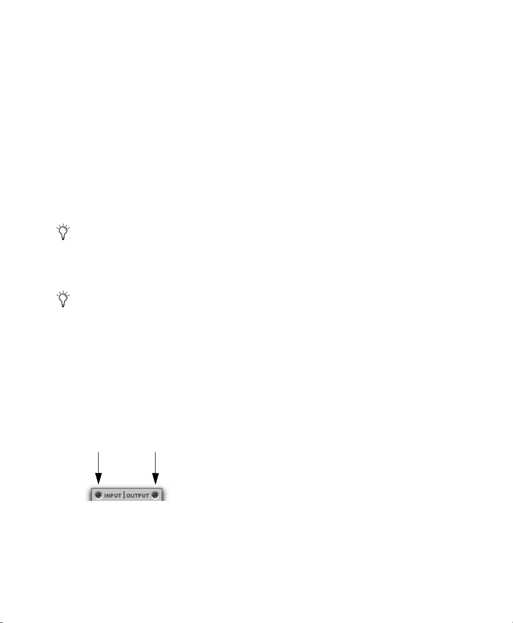
Input and Output Meters
Gain Reduction Meter
The Input (In) and Output (Out) meters show peak
signal levels before and after dynamics processing:
Green
Indicates nominal levels.
Yellow
Indicates pre-clipping levels, starting at
–6 dB below full scale.
Red
Indicates full scale levels (clipping).
The clip indicators at the top of the Output meters
indicate clipping at the input or output stage of the
plug-in. Clip indicators can be cleared by clicking
the indicator.
The Input and Output meters display
differently depending on the type of
track (mono, stereo, or multichannel)
on which the plug-in has been inserted.
When Side-Chain Listen is enabled, the
Output meter only displays the levels of the
side-chain signal. See “Dynamics III SideChain Listen” on page 75.
Toggling Multichannel Input and Output Meters
With multichannel track types LCRS and higher,
both Input and Output meters cannot be shown at
the same time. Click either the Input or Output button to display the appropriate level meter. The Input/Output meters display is toggled to Output by
default.
The Gain Reduction (GR) meter indicates the
amount the input signal is attenuated (in dB) and
shows different colors during dynamics processing:
Light Orange
Indicates that gain reduction is
within the “knee” and has not reached the full ratio
of compression.
Dark Orange
Indicates that gain reduction is being
applied at the full ratio (for example, 2:1).
Threshold Arrow
The orange Threshold arrow next to the Input meter
indicates the current threshold, and can be dragged
up or down to adjust the threshold. When a multichannel instance of the plug-in has been configured
to show only the Output meter, the Threshold arrow is not displayed.
Phase Invert
The Phase Invert button at the top of the Levels section inverts the phase (polarity) of the input signal,
to help compensate for phase anomalies that can
occur either in multi-microphone environments or
because of mis-wired balanced connections.
Input (left) and Output (right) meter buttons
Chapter 13: Dynamics III 64
Page 80

Dynamics III LFE Enable
Input signal
level (x-axis)
Output signal
level (y-axis)
Threshold
(Pro To ols Ultimate Only)
The LFE Enable button (located in the Options section) is on by default, and enables plug-in processing of the LFE (low frequency effects) channel on a
multichannel track formatted for 5.1, 6.1, or 7.1
surround formats. To disable LFE processing, deselect this button.
Use this graph as a visual guideline to see how
much dynamics processing you are applying.
LFE Enable button (Compressor/Limiter III shown)
The LFE Enable button is not available if the
plug-in is not inserted on an applicable track.
Dynamics III Graph Display
The Dynamics Graph display—used with the Compressor/Limiter and Expander/Gate plug-ins—
shows a curve that represents the level of the input
signal (on the horizontal x–axis) and the level of the
output signal (on the vertical y–axis). The orange
vertical line represents the threshold.
Dynamics graph display
The Compressor/Limiter and Expander/Gate plugins also feature an animated, multi-color cursor in
their gain transfer curve displays.
The gain transfer curve of the Compressor/Limiter
and Expander/Gate plug-ins shows a moving ball
cursor that shows the amount of input gain (x-axis)
and gain reduction (y-axis) being applied to the incoming signal.
Gain transfer curve and cursor showing amount of
compression
To indicate overshoots (when an incoming signal
peak is too fast for the current compression setting)
the cursor temporarily leaves the gain transfer
curve.
Chapter 13: Dynamics III 65
Page 81

The cursor changes color to indicate the amount of
compression applied, as shown in the following table:
Cursor Color Compression Amount
white no compression
light orange below full ratio
dark orange full ratio amount
See “De-Esser III Frequency Graph Display”
on page 73 for information on using the
De-Esser graph display.
Dynamics III Side-Chain Section
For information on using the Side-Chain section of
the Compressor/Limiter or Expander/Gate, see
“Using Dynamics III Key Input for Side-Chain
Processing” on page 77.
About Compression
Compression reduces the dynamic range of signals
that exceed a chosen threshold by a specific
amount. The Threshold control sets the level that
the signal must exceed to trigger compression. The
Attack control sets how quickly the compressor responds to the “front” of an audio signal once it
crosses the selected threshold. The Release control
sets the amount of time that it takes for the compressor’s gain to return to its original level after the
input signal drops below the selected threshold.
To use compression most effectively, the attack
time should be set so that signals exceed the threshold level long enough to cause an increase in the
average level. This helps ensure that gain reduction
does not decrease the overall volume too drastically, or eliminate desired attack transients in the
program material.
Of course, compression has many creative uses that
break these rules.
Compressor/Limiter III
The Compressor/Limiter plug-in applies either
compression or limiting to audio material, depending on the ratio of compression used.
About Limiting
Limiting prevents signal peaks from ever exceeding a chosen threshold, and is generally used to prevent short-term peaks from reaching their full amplitude. Used judiciously, limiting produces higher
average levels, while avoiding overload (clipping
or distortion), by limiting only some short-term
transients in the source audio. To prevent the ear
from hearing the gain changes, extremely short attack and release times can be used.
Limiting is used to remove only occasional peaks
because gain reduction on successive peaks would
be noticeable. If audio material contains many
peaks, the threshold should be raised and the gain
Compressor/Limiter III
Chapter 13: Dynamics III 66
manually reduced so that only occasional, extreme
peaks are limited.
Page 82

Limiting generally begins with the ratio set at 10:1
and higher. Large ratios effectively limit the dynamic range of the signal to a specific value by setting an absolute ceiling for the dynamic range.
Compressor/Limiter III
Input/Output Level Meters
The Input and Output meters show peak signal levels before and after dynamics processing. See “Dynamics III Levels Section” on page 63 for more information.
Threshold arrow on input meter
Unlike scales on analog compressors, metering
scales on a digital device reflect a 0 dB value that
indicates full scale (fs)—the full-code signal level.
Compressor/Limiter III Graph
Display
The Dynamics Graph display lets you visually see
how much expansion or gating you are applying to
your audio material. See “Dynamics III Graph Display” on page 65.
Compressor/Limiter III
Threshold Control
The Threshold (Thresh) control sets the level that
an input signal must exceed to trigger compression
or limiting. Signals that exceed this level will be
compressed. Signals that are below it will be unaffected.
This control has an approximate range of –60 dB to
0 dB, with a setting of 0 dB equivalent to no compression or limiting. The default value for the
Threshold control is –24 dB.
An orange arrow on the Input meter indicates the
current threshold, and can also be dragged up or
down to adjust the threshold setting.
The Dynamics Graph display also shows the
threshold as an orange vertical line.
Threshold indicator on Dynamics Graph display
This control ranges from –60 dB (lowest gain) to
0 dB (highest gain).
Compressor/Limiter III Ratio
Control
The Ratio control sets the compression ratio, or the
amount of compression applied as the input signal
exceeds the threshold. For example, a 2:1 compression ratio means that an input level that is 2 dB
above the threshold will be attenuated, resulting in
an output level that is 1 dB over the threshold.
This control ranges from 1:1 (no compression) to
100:1 (hard limiting).
Chapter 13: Dynamics III 67
Page 83

Compressor/Limiter III Attack
Control
Compressor/Limiter III Knee
Control
The Attack control sets the attack time, or the rate
at which gain is reduced after the input signal
crosses the threshold.
The smaller the value, the faster the attack. The
faster the attack, the more rapidly the Compressor/Limiter applies attenuation to the signal. If you
use fast attack times, you should generally use a
proportionally longer release time, particularly
with material that contains many peaks in close
proximity.
This control ranges from 10 s (fastest attack time)
to 300 ms (slowest attack time).
Compressor/Limiter III Release
Control
The Release control sets the length of time it takes
for the Compressor/Limiter to be fully deactivated
after the input signal drops below the threshold.
Release times should be set long enough that if signal levels repeatedly rise above the threshold, the
gain reduction “recovers” smoothly. If the release
time is too short, the gain can rapidly fluctuate as
the compressor repeatedly tries to recover from the
gain reduction. If the release time is too long, a loud
section of the audio material could cause gain reduction that continues through soft sections of program material without recovering.
This control ranges from 5 ms (fastest release time)
to 4 seconds (slowest release time).
The Knee control sets the rate at which the compressor reaches full compression once the threshold
has been exceeded.
As you increase this control, it goes from applying
“hard-knee” compression to “soft-knee” com pre ssion:
• With hard-knee compression, compression be-
gins when the input signal exceeds the threshold.
This can sound abrupt and is ideal for limiting.
• With soft-knee compression, gentle compression
begins and increases gradually as the input signal
approaches the threshold, and reaches full compression after exceeding the threshold. This creates smoother compression.
Graph examples of hard knee (left) and soft knee
(right) compression
For example, a Knee setting of 10 dB would be the
gain range over which the rat io gradually increased
to the set ratio amount.
The Gain Reduction meter displays light orange
while gain reduction has not exceeded the knee setting, and switches to dark orange when gain reduction reaches the full ratio.
This control ranges from 0 db (hardest response) to
30 db (softest response).
Chapter 13: Dynamics III 68
Page 84

Compressor/Limiter III Gain
Control
The Gain control lets you boost overall output gain
to compensate for heavily compressed or limited
signals.
This control ranges from 0 dB (no gain boost) to
+40 dB (loudest gain boost), with the default value
at 0 dB.
For more information on the LFE channel,
refer to the Pro Tools Reference Guide.
Compressor/Limiter III
Side-Chain Section
The side-chain is the split-off signal used by the
plug-in’s detector to trigger dynamics processing.
The Side-Chain section lets you toggle the sidechain between the internal input signal or an external key input, and tailor the equalization of the
side-chain signal so that the triggering of dynamics
processing becomes frequency-sensitive. See “Dynamics III Side-Chain Input” on page 74.
Expander/Gate III
The Expander/Gate plug-in applies expansion or
gating to audio material, depending on the ratio setting.
Expander/Gate III
About Expansion
Expansion decreases the gain of signals that fall below a chosen threshold. They are particularly useful for reducing noise or signal leakage that creeps
into recorded material as its level falls, as often occurs in the case of headphone leakage.
About Gating
Gating silences signals that fall below a chosen
threshold. To enable gating, simply set the Ratio
and Range controls to their maximum values.
Expanders can be thought of as soft noise gates
since they provide a gentler way of reducing noisy
low-level signals than the typically abrupt cutoff of
a gate.
Chapter 13: Dynamics III 69
Page 85

Expander/Gate III
Input/Output Level Meters
Expander/Gate
Control
III
Threshold
The Input and Output meters show peak signal levels before and after dynamics processing. See “Dynamics III Levels Section” on page 63 for more information.
Expander/Gate
III
Dynamics
Graph Display
The Dynamics Graph display lets you visually see
how much expansion or gating you are applying to
your audio material. See “Dynamics III Graph Display” on page 65.
Expander/Gate
III
Look Ahead
Button
Normally, dynamics processing begins when the
level of the input signal crosses the threshold.
When the Look Ahead button is enabled, dynamics
processing begins 2 milliseconds before the level
of the input signal crosses the threshold.
The Threshold (Thresh) control sets the level below which an input signal must fall to trigger expansion or gating. Signals that fall below the
threshold will be reduced in gain. Signals that are
above it will be unaffected.
An orange arrow on the Input meter indicates the
current threshold, and can also be dragged up or
down to adjust the threshold setting.
Threshold arrow on Input meter
The Dynamics Graph display also shows the
threshold as an orange vertical line.
Look Ahead control
The Look Ahead control is useful for avoiding the
loss of transients that may have been otherwise cut
off or trimmed in a signal.
Chapter 13: Dynamics III 70
Threshold indicator on Dynamics Graph display
This control has an approximate range of –60dB to
0 dB, with a setting of 0 dB equivalent to no compression or limiting. The default value for the
Threshold control is –24 dB.
Page 86

Expander/Gate
The Ratio control sets the amount of expansion.
For example, if this is set to 2:1, it will lower signals below the threshold by one half. At higher ratio levels (such as 30:1 or 40:1) the Expander/Gate
functions like a gate by cutting off signals that fall
below the threshold. As you adjust the ratio control,
refer to the built-in graph to see how the shape of
the expansion curve changes.
This control ranges from 1:1 (no expansion) to
100:1 (gating).
Expander/Gate
III
Ratio Control
III
Attack
Control
The Attack control sets the attack time, or the rate
at which gain is reduced after the input signal
crosses the threshold. Use this along with the Ratio
setting to control how soft the Expander’s gain reduction curve is.
This control ranges from 10 s (fastest attack time)
to 300 ms (slowest attack time).
Expander/Gate
The Hold control specifies the duration (in seconds
or milliseconds) during which the Expander/Gate
will stay in effect after the initial attack occurs.
This can be used as a function to keep the Expander/Gate in effect for longer periods of time
with a single crossing of the threshold. It can also
be used to prevent gate chatter that may occur if
varying input levels near the threshold cause the
gate to close and open very rapidly.
III
Hold Control
Expander/Gate
III
Release
Control
The Release control sets how long it takes for the
gate to close after the input signal falls below the
threshold level and the hold time has passed.
This control ranges from 5 ms (fastest release time)
to 4 seconds (slowest release time).
Expander/Gate
The Range control sets the depth of the Expander/Gate when closed. Setting the gate to higher
range levels allows more and more of the gate d audio that falls below the threshold to peek through
the gate at all times.
This control ranges from –80 dB (lowest depth) to
0 dB (highest depth).
Expander/Gate
III
Range Control
III
Side-Chain
Section
The side-chain is the split-off signal used by the
plug-in’s detector to trigger dynamics processing.
The Side-Chain section lets you toggle the sidechain between the internal input signal or an external key input, and tailor the equalization of the
side-chain signal so that the triggering of dynamics
processing becomes frequency-sensitive. See “Dynamics III Side-Chain Input” on page 74.
This control ranges from 5 ms (shortest hold) to
4 seconds (longest hold).
Chapter 13: Dynamics III 71
Page 87

De-Esser III
Gain
Reduction
meter
Input
meter
Output
meter
The De-Esser reduces sibilants and other high frequency noises that can occur in vocals, voiceovers, and wind instruments such as flutes. These
sounds can cause peaks in an audio signal and lead
to distortion.
The De-Esser reduces these unwanted sounds using
fast-acting, frequency-dependent compression.
The Threshold control sets the level above which
compression starts, and the Frequency (Freq) control sets the frequency band in which the De-Esser
operates.
De-Esser III
To improve de-essing of material that has both very
loud and very soft passages, automate the Range
control so that it is lower on soft sections.
.
The De-Esser has no control to directly adjust the threshold level (the level that an inpu t
signal must exceed to trigger de-essing). The
amount of de-essing will vary with the input
signal.
De-Esser III Level Meters
These controls let you track input, output, and gain
reduction levels.
Using De-Essing Effectively
To use de-essing most effectively, insert the De-Esser after compressor or limiter plug-ins.
The Frequency control should be set to remove sibilants (typically the 4–10 kHz range) and not other
parts of the signal. This helps prevent de-essing
from changing the original character of the audio
material in an undesired manner.
Similarly, the Range control should be set to a level
De-Esser III I/O Meter display
Input and Output Meters
The Input and Output meters show peak signal levels before and after dynamics processing:
Green
Indicates nominal levels.
Yellow
Indicates pre-clipping levels, starting at
–6 dB below full scale.
Red
Indicates full scale levels (clipping).
low enough so that de-essing is triggered only by
sibilants. If the Range is set too high, a loud, nonsibilant section of audio material could cause unwanted gain reduction or cause si bilants to be ov erattenuated.
Chapter 13: Dynamics III 72
The Clip indicators at the top of each meter indicate
clipping at the input or output stage of the plug-in.
Clip indicators can be cleared by clicking the indicator.
Page 88

De-Esser III Gain Reduction
Frequency
(x-axis)
Gain
(y-axis)
Frequency
Range
Current gain reduction
Meter
The Gain Reduction meter indicates the amount the
input signal is attenuated, in dB. This meter shows
different colors during de-essing:
Light Orange
applied, but has not reached the maximum level set
by the Range control.
Dark Orange
reached the maximum level set by the Range control.
Indicates that gain reduction is being
Indicates that gain reduction has
De-Esser III Frequency Control
The Frequency (Freq) control sets the frequency
band in which the De-Esser operates. When HF
Only is disabled, gain is reduced in frequencies
within the specified range. When HF Only is enabled, the gain of frequencies above the specified
value will be reduced.
This control ranges from 500 Hz (lowest frequency) to 16 kHz (highest frequency).
De-Esser III Listen Control
When enabled, the Listen button lets you monitor
the sibilant peaks used by the De-Esser as a sidechain to trigger compression. This is useful for listening only to the sibilance for fine-tuning De-Esser controls. To monitor the whole output signal
without this filtering, deselect the Listen button.
De-Esser III Frequency Graph
Display
The De-Esser Frequency Graph display shows a
curve that represents the level of gain reductio n (on
the y-axis) for the range of the output signal's frequency (on the x-axis). The white line represents
the current Frequency setting, and the animated orange line represents the level of gain reduction being applied to the signal.
Use this graph as a visual guideline to see how
much dynamics processing you are applying at different points in the frequency spectrum.
De-Esser III Range Control
The Range control defines the maximum amount of
gain reduction possible when a signal is detected at
the frequency set by the Frequency control.
This control ranges from –40 dB (maximum deessing) to 0 dB (no de-essing).
De-Esser III HF Only Control
When the HF Only button is enabled, gain reduction is applied only to the active frequency band set
by the Frequency control. When the HF Only button is disabled, the De-Esser applies gain reduction
to the entire signal.
Chapter 13: Dynamics III 73
De-Esser graph display
Page 89

Dynamics III Side-Chain Input
(Compressor/Limiter and Expander/Gate Only)
Dynamics processors typically use the detected
amplitude of their input signal to trigger gain reduction. This split-off signal is known as the side-
chain. The Compressor/Limiter and Expander/Gate plug-ins feature external key capabilities and filters for the side-chain.
With external key side-chain processing, you trigger dynamics processing using an external signal
(such as a separate reference track or audio source)
instead of the input signal. This external source is
known as the key input.
With side-chain filters, you can make dynamics
processing more or less sensitive to certain frequencies. For example, you might configure the
side-chain so that certain lower frequencies on a
drum track trigger dynamics processing.
Dynamics III Side-Chain Controls
The controls in the Side-Chain section let you toggle the side-chain between the internal input signal
or an external key input, listen to the side-chain,
and tailor the equalization of the side-chain signal
so that the triggering of dynamics processing becomes frequency-sensitive.
Dynamics III Side-Chain External Key
The External Key toggles external side-chain processing on or off. When this button is highlighted,
the plug-in uses the amplitude of a separate reference track or external audio source to trigger dynamics processing. When this button is dark gray,
the External Key is disabled and the plug-in uses
the amplitude of the input signal to trigger dynamics processing.
External Key button
Compressor/Limiter and Expander/Gate Side-Chain
Chapter 13: Dynamics III 74
Page 90

Dynamics III Side-Chain Listen
When enabled, this control lets you listen to the internal or external side-ch ain inpu t by itse lf, as well
as monitor its levels with the Output meter. This is
especially useful for fine-tuning the plug-in’s filter
settings or external key input.
Dynamics III Side-Chain High-Frequency
(HF) Filter Type
The HF filter section lets you filter higher frequencies out of the side-chain signal so that only certain
bands of high frequencies or lower frequencies
pass through to trigger dynamics processing. The
HF side-chain filter is switchable between Band
Pass and Low Pass filters.
Side-Chain Listen button
Side-Chain Listen is not saved with other
plug-in presets.
Dynamics III Side-Chain HF and LF Filter
Enable Buttons
The HF Filter Enable and LF Filter Enable buttons
toggle the corresponding filter in or out of the sidechain. When this button is highlighted, the filter is
applied to the side-chain signal. When this button is
dark gray, the filter is bypassed and available for
activation.
Band Pass Filter
Makes triggering of dynamics
processing more sensitive to frequencies within the
narrow band centered around the Frequency setting, and rolling off at a slope of 12 dB per octave.
Band-Pass filter
Low Pass Filter
Makes triggering of dynamics processing more sensitive to frequencies below the
Frequency setting rolling off at a slope of 12 dB per
octave.
Low Pass filter
HF and LF Filter Enable buttons
Chapter 13: Dynamics III 75
Page 91

Dynamics III Side-Chain HF Frequency
Control
The HF frequency control sets the frequency position for the Band Pass or Low Pass filter, and
ranges from 20 Hz to 20 kHz.
High Pass Filter
Makes triggering of dynamics
processing more sensitive to frequencies above the
Frequency setting rolling off at a slope of 12 dB per
octave.
High Pass filter
HF frequency controls
Dynamics III Side-Chain Low-Frequency
(LF) Filter Type
The LF filter section lets you filter lower frequencies out of the side-chain signal so that only certain
bands of low frequencies or higher frequencies are
allowed to pass through to trigger dynamics processing. The LF side-chain is switchable between
Band Pass and High Pass filters.
Band-Pass Filter
Makes triggering of dynamics
processing more sensitive to frequencies within the
narrow band centered around the Frequency setting, and rolling off at a slope of 12 dB per octave.
Dynamics III Side-Chain LF Frequency
Control
The Frequency control sets the frequency position
for the Band-Pass or High Pass filter, and ranges
from 20 Hz to 20 kHz.
LF frequency controls
Band-Pass filter
Chapter 13: Dynamics III 76
Page 92

Using Dynamics III Key Input for
Side-Chain Processing
To use a filtered or unfiltered external key input to
trigger dynamics processing:
1 Click the Key Input selector and select the input
or bus carrying the audio from the reference
track or external audio source.
Selecting a Key Input
2 Click External Key to activate external side-
chain processing.
External Key
4 To filter the key input so that only specific fre-
quencies trigger the plug-in, use the HF and LF
controls to select a frequency range.
5 Begin playback. The plug-in uses the input or
bus that you chose as an external key input to
trigger its effect.
6 Adjust the plug-in’s Threshold (Thresh) control
to fine-tune external key input triggering.
Using a Filtered Input Signal for
Side-Chain Processing with
Dynamics III
To use the filtered input signal to trigger dynamics
processing:
1 Ensure the Key Input selector is set to No Key
Input.
Key Input selector
2 Ensure that the External Key button is disabled
(dark gray).
3 To listen to the signal that will be used to control
side-chain input, click Side-Chain Listen to enable it (highlighted).
Side-Chain section
Side-Chain Listen
Chapter 13: Dynamics III 77
Page 93
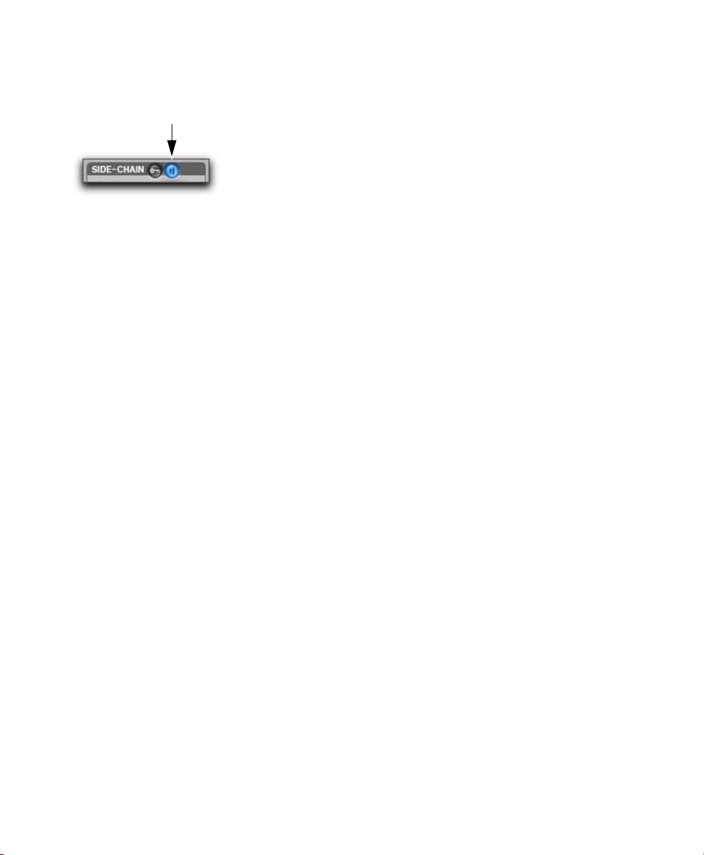
3 To listen to the signal that will be used to control
side-chain input, click Side-Chain Listen to enable it (highlighted).
Side-Chain section
4 To filter the side-chain input so that only specific
frequencies within the input signal trigger the
plug-in, use the HF and LF controls to select a
frequency range.
5 Begin playback. The plug-in uses the filtered in-
put signal to trigger dynamics processing.
6 To fine-tune side-chain triggering, adjust the
plug-in controls.
Chapter 13: Dynamics III 78
Page 94

Chapter 14: Eleven Effects Gray Compressor
Gray Compressor
Inspired by a well-loved ’70s solid-state compressor pedal, Gray Compressor can add singing sustain to leads or lend power and girth to chunky
rhythm guitar parts.
Gray Compressor is available as a Mono (or
Multi-Mono) plug-in only.
Level
The Level control sets the overall output volume of
the effect.
Sustain
The Sustain control lets you adjust the threshold,
and thus, the amount of compression, in the Compressor effect.
Chapter 14: Eleven Effects Gray Compressor 79
Page 95

Chapter 15: Fairchild Plug-Ins
The Fairchild plug-ins are a pair of vintage compressor plug-ins that are available in DSP, Native,
and AudioSuite formats.
The Fairchild plug-ins support 44.1 kHz, 48 kHz,
88.2 kHz, 96 kHz, 176.4 kHz, and 192 kHz sample
rates.
The Fairchild plug-ins operate as mono,
multi-mono, or stereo plug-ins.
Fairchild 660
Fairchild 660
Re-introducing the undisputed champion in price,
weight, and performance: the $35,000, one-hundred pound, Fairchild 660. Avid’s no-compromise
replica captures every detail of this studio classic.
Designed in the early 1950s, the Fairchild 660 is a
variable-mu tube limiter. Variable-mu designs use
an unusual form of vacuum tube that is capable of
changing its gain dynamically.
The result? In addition to featuring a tube audio
stage like the LA-2A, the Fairchild actually
achieves gain reduction through the use of tubes!
The heart of the Fairchild limiter—a 6386 triode —
is one such variable-mu tube. In fact, four of these
tubes are used in parallel. A key part of the Fairchild design, it ensures that the output doesn’t get
darker as the unit goes further into gain reduction,
and also reduces distortion as the tubes are biased
further into Class-B operation.
Tubes, wires, and iron
Chapter 15: Fairchild Plug-Ins 80
Page 96

Fairchild 660 Controls
Fairchild 660 Tips and Tricks
Adjust the Input Gain and Threshold controls together until you get the sound you want. Like many
classic compressors, after a little bit of tweaking,
you’ll know immediately when you get it right.
Input Gain
Input Gain sets the input level to the
unit and the compression threshold, just like the Input control on an 1176. Full clockwise is loudest.
Threshold
Threshold adjusts the gain to the sidechain, just like the Peak Reduction control on an
LA-2A.
Time Constant
Selects the attack and release times
for the compressor. One is fastest, and six is slowest. Seven and eight are custom presets.
5,6,7,8…
The Fairchild manual documents Time Constant
settings 5 and 6 as user presets—although you have
to go inside with a soldering iron to change them.
We used the “factory default” values.
Bonus Settings
Settings 7 and 8 do not exist on real-world units—
well, at least most of them. These settings are taken
from a real-world Fairchild modification invented
by Dave Amels many years before he designed the
plug-in version.
What do they do? Settings 7 and 8 offer versions of
Time Constant 2 with a gentler release useful for
compressing vocals and other program material
where you desire more subtlety in the compression
action. Give them a try—you’ve already heard
them on hit songs on the radio.
Pump It Up
With a carefully adjusted Input Gain and Threshold, you can use Time Constant 1 to achieve a cool
pumping effect on drums. The sound gets darker
and fuller, and sits beautifully in a mix.
Chapter 15: Fairchild Plug-Ins 81
Page 97

Fairchild 670
Avid’s no-compromise replica captures every detail of the Fairchild 670. The Fairchild 670 is a
dual-channel unit and, as such, is only available on
stereo tracks.
Note that the companion Fairchild 660 also supports stereo operation. Both a Fairchild 660 and a
Fairchild 670 were modeled from scratch using two
different hardware units. This gives you a choice of
two different-sounding Fairchild units to try on
your stereo tracks!
Fairchild 670 Controls
Adjust the Input Gain and Threshold controls together on both channels until you get the sound you
want. Like many classic compressors, after a little
bit of tweaking, you’ll know immediately when
you get it right.
Input Gain
compression threshold, just like the Input control
on an 1176. Full clockwise is loudest.
Threshold
like the Peak Reduction control on an LA-2A.
Sets the input level to the unit and the
Adjusts the gain to the sidechain, just
Fairchild 670
The internal design of the Fairchild 670 is similar to
the Fairchild 660. However, the Fairchild 670 offers two channels of compression instead of one.
Combined with the AGC control, this gives you
even more compression options on stereo tracks.
Time Constant
Selects the attack and release times.
One is fastest, and six is slowest. Seven and eight
are custom presets. See “Fairchild 670” on page 82
for details on these custom settings.
AGC
Lets you select Left/Right processing or
Lat/Vert processing of the two channels. Left/Right
works like a dual-mono compressor with separate
controls for the left and right channels. In Lat/Vert
mode the top row of controls affects the in-phase
(Lat) information and the bottom row of controls
affects the out of phase (Vert) information. Although originally designed for vinyl mastering
where excess Vert (vertical) information could
cause the needle to jump out of the groove, you can
use the Lat/Vert mode to achieve some amazing effects – especially on drums.
Fairchild 670 Tips and Tricks
To exactly match the settings between channels,
hold down the Shift key while adjusting a control.
This is useful when trying to preserve the existing
Left/Right balance on stereo material.
Chapter 15: Fairchild Plug-Ins 82
Page 98

Chapter 16: Focusrite D3
Focusrite D3 is a high-quality dynamics processor
plug-in. Developed in cooperation with Focusrite,
the D3 is based on the highly acclaimed
Red Range 3
™
dual mono/stereo compressor &
limiter designed by Rupert Neve.
D3 is available in DSP, Native, and AudioSuite
formats.
D3 supports 44.1 kHz, 48 kHz, 88.2 kHz, 96 kHz,
176.4 kHz, and 192 kHz sample rates.
D3 operates as a mono, multi-mono, or stereo plug-
in.
Focusrite D3
D3 features include:
Compressor+Limiter . This configuration allows
you to use both the compressor and the limiter at
the same time. The Compressor+Limiter plug-in
requires twice as much DSP as the Compressor/Limiter.
Compressor/Limiter. This configuration allows
you to use either the compressor or the limiter—but
not both at the same time. The Compressor/Limiter
plug-in uses half as much DSP as the Compressor+Limiter . It is provided so t hat you can conserve
DSP , since you may not need both compression and
limiting at the same time.
The Compressor/Limiter defaults to the compressor being enabled and the limiter disabled.
D3 Compressor
The D3 compressor reduces the dynamic range of
audio signals that exceed a user-selectable threshold by a specific amount. This is accomplished by
reducing output levels as input levels increase
above the threshold.
The amount of output level reduction that D3 applies as input levels increase is referred to as the
compression ratio. This parameter is adjustable. If
you set the compression ratio to 2:1, for example,
for each 2 dB that the signal exceeds the thre shold,
the output level will be reduced to 1 dB above the
threshold. With a compression ratio of 4 :1, an 8 dB
increase in input will produce only a 2 dB increase
in output.
Chapter 16: Focusrite D3 83
Page 99

D3 Limiter
Compressor
Limiter
D3 Side-Chain Processing
The D3 limiter operates as a fast-attack compressor
with a high compression ratio. It does not attack instantaneously or look ahead in or der to attack ahead
of time, but instead uses a very fast, 1-millisecond
attack time. As such, the D3 is not a “brick wall”
limiter, but limits the overall dynamic range of signals in a sonically-pleasing way.
Like the Compressor, the Limiter is activated when
the signal exceeds the user-selected threshold. The
Limiter then compresses any signal above the selected threshold down to the threshold limit that
you have set.
To enable the limiter:
1 Disable the compressor by Control-clicking
(Mac) or Start-clicking (Windows) its icon.
2 Click the Limiter icon.
Compressors and limiters generally use the detected amplitude of the input signal as a control
source. Other signals can also be used as a control
source by using a key input. With de-essing, for example, a frequency-modified version of the input
signal is used as a trigger. This is known as sidechain processing.
Side-chain processing allows the D3 compression
or limiting to be controlled by another independent
audio signal. In this way you can compress or limit
one track’s audio using the dynamics of a different
track’s audio.
Using D3 in Stereo
In stereo configurations, all D3 controls except the
Input Level affect both channels of the stereo signal. The D3 RMS detector (which derives the control signal that drives the dynamics processing)
uses a composite of the two channels. Because of
this, when stereo processing occurs, there is no image shift when signal levels differ between the two
channels (since the composite control signal drives
processing for both channels).
Compressor and Limiter icons
Chapter 16: Focusrite D3 84
Page 100

D3 Common Controls
External
Key
Key Listen
Input Level
Input Level attenuates signal input level to the
compressor or limiter. The range of this control is
from –30 dB to 0 dB.
When you use the stereo version of the D3 plug-in,
each channel has its own separate Input Level
knob. To adjust input levels for both channels simultaneously, Shift-drag. Option-Shift clicking
(Mac) or Alt-Shift-clicking (Windows) either Input
Level knob resets both channels to 0 dB.
Input Level
Output Level
Output Level adjusts the overall output gain. Because large amounts of compression can restrict
dynamic range, the Output Level knob is useful for
compensating for heavily compressed signals and
making up the resulting difference in level.
When you use the stereo version of the D3 plug-in,
this single knob controls the master output for both
channels. The range of this control is from –12 dB
of attenuation to +18 dB of gain.
External Key and Key Listen
The side-chain is the split-off sign al used by a plugin’s detector to trigger dynamics processing. External Key lets you designate an external source
(known as the key input) for the side-chain, while
Key Listen lets you monitor the key input.
External Key and Key Listen toggles
See “Using the Side-Chain Input in D3” on
page 88 for detailed information on external
side-chain processing.
Meters
The meters indicate gain reduction (the top meter)
and output level (the bottom meter). The Gain Reduction meter indicates the amount of gain reduction in dB. The Output Level meter indicates the
output signal level in dB.
In Stereo mode, two Output Level meters appear,
one for each channel. However, a single Gain Reduction meter is used for both channels, since the
D3 RMS detector uses a composite control signal.
A red Clip Indicator appears to the right of the output meter(s). Clicking on the Clip Indicator clears
it. Option-clicking (Mac) or Alt-clicking (Windows) clears both channels when the plug-in is
used in stereo.
Output Level
Meters
Chapter 16: Focusrite D3 85
 Loading...