

Page 1

Audio Plug-Ins Guide
Version 10.0
Page 2

Legal Notices
This guide is copyrighted ©2011 by Avid Technology, Inc.,
(hereafter “Avid”), with all rights reserved. Under copyright
laws, this guide may not be duplicated in whole or in part
without the written consent of Avid.
003, 96 I/O, 96i I/O, 192 Digital I/O, 192 I/O, 888|24 I/O,
882|20 I/O, 1622 I/O, 24-Bit ADAT Bridge I/O, AudioSuite,
Avid, Avid DNA, Avid Mojo, Avid Unity, Avid Unity ISIS,
Avid Xpress, AVoption, Axiom, Beat Detective,
Bomb Factory, Bruno, C|24, Command|8, Control|24,
D-Command, D-Control, D-Fi, D-fx, D-Show, D-Verb, DAE,
Digi 002, DigiBase, DigiDelivery, Digidesign,
Digidesign Audio Engine, Digidesign Intelligent Noise
Reduction, Digidesign TDM Bus, DigiDrive, DigiRack,
DigiTest, DigiTranslator, DINR, DV Toolkit, EditPack, Eleven,
HD Core, HD I/O, HD MADI, HD OMNI, HD Process, Hybrid,
Impact, Interplay, LoFi, M-Audio, MachineControl, Maxim,
Mbox, MediaComposer, MIDI I/O, MIX, MultiShell, Nitris,
OMF, OMF Interchange, PRE, ProControl, Pro Tools,
Pro Tools|HD, QuickPunch, Recti-Fi, Reel Tape, Reso,
Reverb One, ReVibe, RTAS, Sibelius, Smack!,
SoundReplacer, Sound Designer II, Strike, Structure,
SYNC HD, SYNC I/O, Synchronic, TL Aggro, TL AutoPan,
TL Drum Rehab, TL Everyphase, TL Fauxlder, TL In Tune,
TL MasterMeter, TL Metro, TL Space, TL Utilities, Transfuser,
Trillium Lane Labs, Vari-Fi, Velvet, X-Form, and XMON are
trademarks or registered trademarks of Avid Technology, Inc.
Xpand! is Registered in the U.S. Pat ent and Trademark Office.
All other trademarks are the property of their respective
owners.
Product features, specifications, system requirements, and
availability are subject to change without notice.
Guide Part Number 9329-65100-00 REV A 10/11
Documentation Feedback
At Avid, we are always looking for ways to improve our
documentation. If you have comments, corrections, or
suggestions regarding our documentation, email us at
techpubs@avid.com.
Page 3

Contents
Part I Introduction to Pro Tools Plug-Ins
Chapter 1. Audio Plug-Ins Overview . . . . . . . . . . . . . . . . . . . . . . . . . . . . . . . . . . . . . . . . . . . . . . 3
Avid Audio Plug-Ins . . . . . . . . . . . . . . . . . . . . . . . . . . . . . . . . . . . . . . . . . . . . . . . . . . . . . . . 3
Plug-In Formats. . . . . . . . . . . . . . . . . . . . . . . . . . . . . . . . . . . . . . . . . . . . . . . . . . . . . . . . . . 5
Using Plug-Ins in Pro Tools . . . . . . . . . . . . . . . . . . . . . . . . . . . . . . . . . . . . . . . . . . . . . . . . . 6
Conventions Used in Pro Tools Documentation. . . . . . . . . . . . . . . . . . . . . . . . . . . . . . . . . . . 7
System Requirements and Compatibility for Plug-Ins. . . . . . . . . . . . . . . . . . . . . . . . . . . . . . . 7
Contents of the Boxed Version of Your Plug-In . . . . . . . . . . . . . . . . . . . . . . . . . . . . . . . . . . . 8
About www.avid.com . . . . . . . . . . . . . . . . . . . . . . . . . . . . . . . . . . . . . . . . . . . . . . . . . . . . . . 8
Chapter 2. Installing Plug-Ins . . . . . . . . . . . . . . . . . . . . . . . . . . . . . . . . . . . . . . . . . . . . . . . . . . . . 9
Free Pro Tools Plug-Ins . . . . . . . . . . . . . . . . . . . . . . . . . . . . . . . . . . . . . . . . . . . . . . . . . . . . 9
Free VENUE Plug-Ins . . . . . . . . . . . . . . . . . . . . . . . . . . . . . . . . . . . . . . . . . . . . . . . . . . . . . 9
Updating Older Plug-Ins. . . . . . . . . . . . . . . . . . . . . . . . . . . . . . . . . . . . . . . . . . . . . . . . . . . . 9
Using Pro Tools Plug-Ins with Avid Media Composer. . . . . . . . . . . . . . . . . . . . . . . . . . . . . . . 9
Installing Plug-Ins for Pro Tools . . . . . . . . . . . . . . . . . . . . . . . . . . . . . . . . . . . . . . . . . . . . . 10
Installing Plug-Ins for VENUE Systems. . . . . . . . . . . . . . . . . . . . . . . . . . . . . . . . . . . . . . . . 10
Authorizing Paid Plug-Ins . . . . . . . . . . . . . . . . . . . . . . . . . . . . . . . . . . . . . . . . . . . . . . . . . . 10
Removing Plug-Ins for Pro Tools . . . . . . . . . . . . . . . . . . . . . . . . . . . . . . . . . . . . . . . . . . . . 12
Removing Plug-Ins for VENUE Systems . . . . . . . . . . . . . . . . . . . . . . . . . . . . . . . . . . . . . . . 12
Part II EQ Plug-Ins
Chapter 3. AIR Kill EQ . . . . . . . . . . . . . . . . . . . . . . . . . . . . . . . . . . . . . . . . . . . . . . . . . . . . . . . . . 15
Kill EQ Controls. . . . . . . . . . . . . . . . . . . . . . . . . . . . . . . . . . . . . . . . . . . . . . . . . . . . . . . . . 15
Chapter 4. EQ III . . . . . . . . . . . . . . . . . . . . . . . . . . . . . . . . . . . . . . . . . . . . . . . . . . . . . . . . . . . . . . 17
EQ III Configurations . . . . . . . . . . . . . . . . . . . . . . . . . . . . . . . . . . . . . . . . . . . . . . . . . . . . . 17
Adjusting EQ III Controls . . . . . . . . . . . . . . . . . . . . . . . . . . . . . . . . . . . . . . . . . . . . . . . . . . 18
EQ III I/O Controls . . . . . . . . . . . . . . . . . . . . . . . . . . . . . . . . . . . . . . . . . . . . . . . . . . . . . . . 20
Contents iii
Page 4

EQ III EQ Band Controls . . . . . . . . . . . . . . . . . . . . . . . . . . . . . . . . . . . . . . . . . . . . . . . . . . 21
EQ III Frequency Graph Display . . . . . . . . . . . . . . . . . . . . . . . . . . . . . . . . . . . . . . . . . . . . 23
7 Band EQ III . . . . . . . . . . . . . . . . . . . . . . . . . . . . . . . . . . . . . . . . . . . . . . . . . . . . . . . . . . 24
2–4 Band EQ III . . . . . . . . . . . . . . . . . . . . . . . . . . . . . . . . . . . . . . . . . . . . . . . . . . . . . . . . 29
1 Band EQ III . . . . . . . . . . . . . . . . . . . . . . . . . . . . . . . . . . . . . . . . . . . . . . . . . . . . . . . . . . 30
Chapter 5. JOEMEEK VC5 Meequalizer. . . . . . . . . . . . . . . . . . . . . . . . . . . . . . . . . . . . . . . . . . . 33
JOEMEEK Meequalizer Controls . . . . . . . . . . . . . . . . . . . . . . . . . . . . . . . . . . . . . . . . . . . . 33
Chapter 6. Pultec Plug-Ins . . . . . . . . . . . . . . . . . . . . . . . . . . . . . . . . . . . . . . . . . . . . . . . . . . . . . 35
Pultec EQP-1A . . . . . . . . . . . . . . . . . . . . . . . . . . . . . . . . . . . . . . . . . . . . . . . . . . . . . . . . . 35
Pultec EQH-2 . . . . . . . . . . . . . . . . . . . . . . . . . . . . . . . . . . . . . . . . . . . . . . . . . . . . . . . . . . 36
Pultec MEQ-5. . . . . . . . . . . . . . . . . . . . . . . . . . . . . . . . . . . . . . . . . . . . . . . . . . . . . . . . . . 37
Part III Dynamics Plug-Ins
Chapter 7. BF-2A. . . . . . . . . . . . . . . . . . . . . . . . . . . . . . . . . . . . . . . . . . . . . . . . . . . . . . . . . . . . . 41
BF-2A Controls. . . . . . . . . . . . . . . . . . . . . . . . . . . . . . . . . . . . . . . . . . . . . . . . . . . . . . . . . 42
BF-2A Tips and Tricks. . . . . . . . . . . . . . . . . . . . . . . . . . . . . . . . . . . . . . . . . . . . . . . . . . . . 43
Chapter 8. BF-3A . . . . . . . . . . . . . . . . . . . . . . . . . . . . . . . . . . . . . . . . . . . . . . . . . . . . . . . . . . . . 45
BF-3A Controls. . . . . . . . . . . . . . . . . . . . . . . . . . . . . . . . . . . . . . . . . . . . . . . . . . . . . . . . . 45
BF-3A Tips and Tricks. . . . . . . . . . . . . . . . . . . . . . . . . . . . . . . . . . . . . . . . . . . . . . . . . . . . 46
Chapter 9. BF76. . . . . . . . . . . . . . . . . . . . . . . . . . . . . . . . . . . . . . . . . . . . . . . . . . . . . . . . . . . . . . 47
BF76 Controls. . . . . . . . . . . . . . . . . . . . . . . . . . . . . . . . . . . . . . . . . . . . . . . . . . . . . . . . . . 47
BF76 Tips and Tricks . . . . . . . . . . . . . . . . . . . . . . . . . . . . . . . . . . . . . . . . . . . . . . . . . . . . 48
Chapter 10. Channel Strip. . . . . . . . . . . . . . . . . . . . . . . . . . . . . . . . . . . . . . . . . . . . . . . . . . . . . . 49
Sections and Panes . . . . . . . . . . . . . . . . . . . . . . . . . . . . . . . . . . . . . . . . . . . . . . . . . . . . . 49
Input. . . . . . . . . . . . . . . . . . . . . . . . . . . . . . . . . . . . . . . . . . . . . . . . . . . . . . . . . . . . . . . . . 51
Output . . . . . . . . . . . . . . . . . . . . . . . . . . . . . . . . . . . . . . . . . . . . . . . . . . . . . . . . . . . . . . . 52
FX Chain . . . . . . . . . . . . . . . . . . . . . . . . . . . . . . . . . . . . . . . . . . . . . . . . . . . . . . . . . . . . . 53
Dynamics . . . . . . . . . . . . . . . . . . . . . . . . . . . . . . . . . . . . . . . . . . . . . . . . . . . . . . . . . . . . . 54
EQ/Filters. . . . . . . . . . . . . . . . . . . . . . . . . . . . . . . . . . . . . . . . . . . . . . . . . . . . . . . . . . . . . 59
Audio Plug-Ins Guideiv
Page 5

Chapter 11. Dynamics III . . . . . . . . . . . . . . . . . . . . . . . . . . . . . . . . . . . . . . . . . . . . . . . . . . . . . . . 65
Dynamics III Shared Features and Controls . . . . . . . . . . . . . . . . . . . . . . . . . . . . . . . . . . . . 65
Compressor/Limiter III . . . . . . . . . . . . . . . . . . . . . . . . . . . . . . . . . . . . . . . . . . . . . . . . . . . . 68
Expander/Gate III. . . . . . . . . . . . . . . . . . . . . . . . . . . . . . . . . . . . . . . . . . . . . . . . . . . . . . . . 71
De-Esser III. . . . . . . . . . . . . . . . . . . . . . . . . . . . . . . . . . . . . . . . . . . . . . . . . . . . . . . . . . . . 73
Dynamics III Side-Chain Input . . . . . . . . . . . . . . . . . . . . . . . . . . . . . . . . . . . . . . . . . . . . . . 75
Chapter 12. Fairchild Plug-Ins. . . . . . . . . . . . . . . . . . . . . . . . . . . . . . . . . . . . . . . . . . . . . . . . . . . 81
Fairchild 660 . . . . . . . . . . . . . . . . . . . . . . . . . . . . . . . . . . . . . . . . . . . . . . . . . . . . . . . . . . . 81
Fairchild 670 . . . . . . . . . . . . . . . . . . . . . . . . . . . . . . . . . . . . . . . . . . . . . . . . . . . . . . . . . . . 83
Chapter 13. Impact. . . . . . . . . . . . . . . . . . . . . . . . . . . . . . . . . . . . . . . . . . . . . . . . . . . . . . . . . . . . 85
Impact Controls . . . . . . . . . . . . . . . . . . . . . . . . . . . . . . . . . . . . . . . . . . . . . . . . . . . . . . . . . 85
Using the Impact Compressor . . . . . . . . . . . . . . . . . . . . . . . . . . . . . . . . . . . . . . . . . . . . . . 88
Chapter 14. JOEMEEK SC2 Compresso r. . . . . . . . . . . . . . . . . . . . . . . . . . . . . . . . . . . . . . . . . . 91
JOEMEEK Compressor Controls . . . . . . . . . . . . . . . . . . . . . . . . . . . . . . . . . . . . . . . . . . . . 91
JOEMEEK Compressor Tips and Tricks . . . . . . . . . . . . . . . . . . . . . . . . . . . . . . . . . . . . . . . 92
Chapter 15. Maxim . . . . . . . . . . . . . . . . . . . . . . . . . . . . . . . . . . . . . . . . . . . . . . . . . . . . . . . . . . . . 93
About Peak Limiting. . . . . . . . . . . . . . . . . . . . . . . . . . . . . . . . . . . . . . . . . . . . . . . . . . . . . . 93
Maxim Controls and Meters . . . . . . . . . . . . . . . . . . . . . . . . . . . . . . . . . . . . . . . . . . . . . . . . 95
Using Maxim . . . . . . . . . . . . . . . . . . . . . . . . . . . . . . . . . . . . . . . . . . . . . . . . . . . . . . . . . . . 98
Maxim and Mastering. . . . . . . . . . . . . . . . . . . . . . . . . . . . . . . . . . . . . . . . . . . . . . . . . . . . . 98
Chapter 16. Purple Audio MC77 . . . . . . . . . . . . . . . . . . . . . . . . . . . . . . . . . . . . . . . . . . . . . . . . . 99
Chapter 17. Slightly Rude Compressor . . . . . . . . . . . . . . . . . . . . . . . . . . . . . . . . . . . . . . . . . . 101
Slightly Rude Compressor Controls . . . . . . . . . . . . . . . . . . . . . . . . . . . . . . . . . . . . . . . . . 101
Slightly Rude Compressor Tips and Tricks . . . . . . . . . . . . . . . . . . . . . . . . . . . . . . . . . . . . 102
Chapter 18. Smack! . . . . . . . . . . . . . . . . . . . . . . . . . . . . . . . . . . . . . . . . . . . . . . . . . . . . . . . . . . 103
Smack! Controls and Meters. . . . . . . . . . . . . . . . . . . . . . . . . . . . . . . . . . . . . . . . . . . . . . . 104
Using the Smack! Compressor/Limiter . . . . . . . . . . . . . . . . . . . . . . . . . . . . . . . . . . . . . . . 108
Chapter 19. TL Aggro. . . . . . . . . . . . . . . . . . . . . . . . . . . . . . . . . . . . . . . . . . . . . . . . . . . . . . . . . 111
TL Aggro Overview . . . . . . . . . . . . . . . . . . . . . . . . . . . . . . . . . . . . . . . . . . . . . . . . . . . . . 111
TL Aggro Controls . . . . . . . . . . . . . . . . . . . . . . . . . . . . . . . . . . . . . . . . . . . . . . . . . . . . . . 113
Using the TL Aggro Side-Chain Input . . . . . . . . . . . . . . . . . . . . . . . . . . . . . . . . . . . . . . . . 115
Contents v
Page 6

Part IV Pitch Shift Plug-Ins
Chapter 20. AIR Frequency Shifter . . . . . . . . . . . . . . . . . . . . . . . . . . . . . . . . . . . . . . . . . . . . . 119
Frequency Shifter Controls . . . . . . . . . . . . . . . . . . . . . . . . . . . . . . . . . . . . . . . . . . . . . . . 119
Chapter 21. Pitch. . . . . . . . . . . . . . . . . . . . . . . . . . . . . . . . . . . . . . . . . . . . . . . . . . . . . . . . . . . . 121
Pitch Controls. . . . . . . . . . . . . . . . . . . . . . . . . . . . . . . . . . . . . . . . . . . . . . . . . . . . . . . . . 121
Relative Pitch Entry (Musical Staff) . . . . . . . . . . . . . . . . . . . . . . . . . . . . . . . . . . . . . . . . . 122
Chapter 22. Pitch Shift . . . . . . . . . . . . . . . . . . . . . . . . . . . . . . . . . . . . . . . . . . . . . . . . . . . . . . . 125
Pitch Shift Controls . . . . . . . . . . . . . . . . . . . . . . . . . . . . . . . . . . . . . . . . . . . . . . . . . . . . . 125
Chapter 23. Time Shift. . . . . . . . . . . . . . . . . . . . . . . . . . . . . . . . . . . . . . . . . . . . . . . . . . . . . . . . 127
Time Shift Controls . . . . . . . . . . . . . . . . . . . . . . . . . . . . . . . . . . . . . . . . . . . . . . . . . . . . . 127
AudioSuite Input Modes and Time Shift . . . . . . . . . . . . . . . . . . . . . . . . . . . . . . . . . . . . . . 132
AudioSuite Preview and Time Shift . . . . . . . . . . . . . . . . . . . . . . . . . . . . . . . . . . . . . . . . . 132
Time Shift as AudioSuite TCE Plug-In Preference. . . . . . . . . . . . . . . . . . . . . . . . . . . . . . . 132
Processing Audio Using Time Shift . . . . . . . . . . . . . . . . . . . . . . . . . . . . . . . . . . . . . . . . . 132
Post Production Pull Up and Pull Down Tasks with Time Shift. . . . . . . . . . . . . . . . . . . . . . 134
Chapter 24. Vari-Fi. . . . . . . . . . . . . . . . . . . . . . . . . . . . . . . . . . . . . . . . . . . . . . . . . . . . . . . . . . . 135
Chapter 25. X-Form. . . . . . . . . . . . . . . . . . . . . . . . . . . . . . . . . . . . . . . . . . . . . . . . . . . . . . . . . . 137
X-Form Displays and Controls Overview . . . . . . . . . . . . . . . . . . . . . . . . . . . . . . . . . . . . . 137
X-Form AudioSuite Input Modes . . . . . . . . . . . . . . . . . . . . . . . . . . . . . . . . . . . . . . . . . . . 141
AudioSuite TCE Plug-In Preference. . . . . . . . . . . . . . . . . . . . . . . . . . . . . . . . . . . . . . . . . 141
Processing Audio Using X-Form . . . . . . . . . . . . . . . . . . . . . . . . . . . . . . . . . . . . . . . . . . . 142
Using X-Form for Post Production Pull Up and Pull Down Tasks . . . . . . . . . . . . . . . . . . . . 143
Part V Reverb Plug-Ins
Chapter 26. AIR Non-Linear Reverb. . . . . . . . . . . . . . . . . . . . . . . . . . . . . . . . . . . . . . . . . . . . . 147
Chapter 27. AIR Reverb. . . . . . . . . . . . . . . . . . . . . . . . . . . . . . . . . . . . . . . . . . . . . . . . . . . . . . . 149
Reverb Controls . . . . . . . . . . . . . . . . . . . . . . . . . . . . . . . . . . . . . . . . . . . . . . . . . . . . . . . 149
Chapter 28. AIR Spring Reverb . . . . . . . . . . . . . . . . . . . . . . . . . . . . . . . . . . . . . . . . . . . . . . . . 153
Spring Reverb Controls. . . . . . . . . . . . . . . . . . . . . . . . . . . . . . . . . . . . . . . . . . . . . . . . . . 153
Audio Plug-Ins Guidevi
Page 7

Chapter 29. D-Verb. . . . . . . . . . . . . . . . . . . . . . . . . . . . . . . . . . . . . . . . . . . . . . . . . . . . . . . . . . . 155
D-Verb Controls. . . . . . . . . . . . . . . . . . . . . . . . . . . . . . . . . . . . . . . . . . . . . . . . . . . . . . . . 155
Chapter 30. Reverb One. . . . . . . . . . . . . . . . . . . . . . . . . . . . . . . . . . . . . . . . . . . . . . . . . . . . . . . 159
A Reverb Overview . . . . . . . . . . . . . . . . . . . . . . . . . . . . . . . . . . . . . . . . . . . . . . . . . . . . . 160
Reverb One Controls . . . . . . . . . . . . . . . . . . . . . . . . . . . . . . . . . . . . . . . . . . . . . . . . . . . . 161
Reverb One Graphs. . . . . . . . . . . . . . . . . . . . . . . . . . . . . . . . . . . . . . . . . . . . . . . . . . . . . 165
Other Reverb One Controls . . . . . . . . . . . . . . . . . . . . . . . . . . . . . . . . . . . . . . . . . . . . . . . 167
Chapter 31. ReVibe. . . . . . . . . . . . . . . . . . . . . . . . . . . . . . . . . . . . . . . . . . . . . . . . . . . . . . . . . . . 169
Reverberation Concepts. . . . . . . . . . . . . . . . . . . . . . . . . . . . . . . . . . . . . . . . . . . . . . . . . . 170
Using ReVibe . . . . . . . . . . . . . . . . . . . . . . . . . . . . . . . . . . . . . . . . . . . . . . . . . . . . . . . . . 171
Adjusting ReVibe Parameters. . . . . . . . . . . . . . . . . . . . . . . . . . . . . . . . . . . . . . . . . . . . . . 172
ReVibe Controls . . . . . . . . . . . . . . . . . . . . . . . . . . . . . . . . . . . . . . . . . . . . . . . . . . . . . . . 173
ReVibe Decay Color & EQ Section Controls . . . . . . . . . . . . . . . . . . . . . . . . . . . . . . . . . . . 180
ReVibe Contour Display. . . . . . . . . . . . . . . . . . . . . . . . . . . . . . . . . . . . . . . . . . . . . . . . . . 183
ReVibe Input/Output Meter. . . . . . . . . . . . . . . . . . . . . . . . . . . . . . . . . . . . . . . . . . . . . . . . 184
ReVibe Online Help Button. . . . . . . . . . . . . . . . . . . . . . . . . . . . . . . . . . . . . . . . . . . . . . . . 184
ReVibe Room Types . . . . . . . . . . . . . . . . . . . . . . . . . . . . . . . . . . . . . . . . . . . . . . . . . . . . 185
Chapter 32. TL Space TDM and TL Space Native . . . . . . . . . . . . . . . . . . . . . . . . . . . . . . . . . . 189
TL Space Feature Highlights . . . . . . . . . . . . . . . . . . . . . . . . . . . . . . . . . . . . . . . . . . . . . . 190
TL Space Overview . . . . . . . . . . . . . . . . . . . . . . . . . . . . . . . . . . . . . . . . . . . . . . . . . . . . . 191
TL Space and System Performance . . . . . . . . . . . . . . . . . . . . . . . . . . . . . . . . . . . . . . . . . 194
Impulse Response (IR) and TL Space. . . . . . . . . . . . . . . . . . . . . . . . . . . . . . . . . . . . . . . . 197
TL Space Presets . . . . . . . . . . . . . . . . . . . . . . . . . . . . . . . . . . . . . . . . . . . . . . . . . . . . . . 200
TL Space Snapshots . . . . . . . . . . . . . . . . . . . . . . . . . . . . . . . . . . . . . . . . . . . . . . . . . . . . 201
TL Space Controls and Displays. . . . . . . . . . . . . . . . . . . . . . . . . . . . . . . . . . . . . . . . . . . . 202
TL Space Display Area. . . . . . . . . . . . . . . . . . . . . . . . . . . . . . . . . . . . . . . . . . . . . . . . . . . 203
TL Space IR Browser. . . . . . . . . . . . . . . . . . . . . . . . . . . . . . . . . . . . . . . . . . . . . . . . . . . . 206
TL Space Primary Controls. . . . . . . . . . . . . . . . . . . . . . . . . . . . . . . . . . . . . . . . . . . . . . . . 208
TL Space Group Selectors and Controls . . . . . . . . . . . . . . . . . . . . . . . . . . . . . . . . . . . . . . 209
TL Space Info Screen . . . . . . . . . . . . . . . . . . . . . . . . . . . . . . . . . . . . . . . . . . . . . . . . . . . 211
Using TL Space. . . . . . . . . . . . . . . . . . . . . . . . . . . . . . . . . . . . . . . . . . . . . . . . . . . . . . . . 212
TL Space IR Library. . . . . . . . . . . . . . . . . . . . . . . . . . . . . . . . . . . . . . . . . . . . . . . . . . . . . 214
Contents vii
Page 8

Part VI Delay Plug-Ins
Chapter 33. AIR Dynamic Delay. . . . . . . . . . . . . . . . . . . . . . . . . . . . . . . . . . . . . . . . . . . . . . . . 217
Dynamic Delay Controls . . . . . . . . . . . . . . . . . . . . . . . . . . . . . . . . . . . . . . . . . . . . . . . . . 217
Chapter 34. AIR Multi-Delay . . . . . . . . . . . . . . . . . . . . . . . . . . . . . . . . . . . . . . . . . . . . . . . . . . . 221
Multi-Delay Controls . . . . . . . . . . . . . . . . . . . . . . . . . . . . . . . . . . . . . . . . . . . . . . . . . . . . 221
Chapter 35. Mod Delay II. . . . . . . . . . . . . . . . . . . . . . . . . . . . . . . . . . . . . . . . . . . . . . . . . . . . . . 223
Mod Delay II Controls . . . . . . . . . . . . . . . . . . . . . . . . . . . . . . . . . . . . . . . . . . . . . . . . . . . 224
Multichannel Mod Delay II . . . . . . . . . . . . . . . . . . . . . . . . . . . . . . . . . . . . . . . . . . . . . . . . 226
Selecting Audio for ModDelay II AudioSuite Processing . . . . . . . . . . . . . . . . . . . . . . . . . . 226
Chapter 36. Mod Delay III . . . . . . . . . . . . . . . . . . . . . . . . . . . . . . . . . . . . . . . . . . . . . . . . . . . . . 227
Mod Delay III Controls. . . . . . . . . . . . . . . . . . . . . . . . . . . . . . . . . . . . . . . . . . . . . . . . . . . 227
Selections for Mod Delay III AudioSuite Processing . . . . . . . . . . . . . . . . . . . . . . . . . . . . . 229
Chapter 37. Moogerfooger Analog Delay . . . . . . . . . . . . . . . . . . . . . . . . . . . . . . . . . . . . . . . . 231
Moogerfooger Analog Delay Controls. . . . . . . . . . . . . . . . . . . . . . . . . . . . . . . . . . . . . . . . 232
Chapter 38. Multi-Tap Delay. . . . . . . . . . . . . . . . . . . . . . . . . . . . . . . . . . . . . . . . . . . . . . . . . . . 233
Multi-Tap Delay Controls. . . . . . . . . . . . . . . . . . . . . . . . . . . . . . . . . . . . . . . . . . . . . . . . . 233
Chapter 39. Ping-Pong Delay . . . . . . . . . . . . . . . . . . . . . . . . . . . . . . . . . . . . . . . . . . . . . . . . . . 235
Ping-Pong Delay Controls . . . . . . . . . . . . . . . . . . . . . . . . . . . . . . . . . . . . . . . . . . . . . . . . 235
Chapter 40. Reel Tape Delay . . . . . . . . . . . . . . . . . . . . . . . . . . . . . . . . . . . . . . . . . . . . . . . . . . 237
Reel Tape Common Controls. . . . . . . . . . . . . . . . . . . . . . . . . . . . . . . . . . . . . . . . . . . . . . 238
Reel Tape Delay Controls . . . . . . . . . . . . . . . . . . . . . . . . . . . . . . . . . . . . . . . . . . . . . . . . 238
Chapter 41. Tel-Ray Variable Delay . . . . . . . . . . . . . . . . . . . . . . . . . . . . . . . . . . . . . . . . . . . . . 241
Tel-Ray Controls. . . . . . . . . . . . . . . . . . . . . . . . . . . . . . . . . . . . . . . . . . . . . . . . . . . . . . . 242
Tel-Ray Tips and Tricks. . . . . . . . . . . . . . . . . . . . . . . . . . . . . . . . . . . . . . . . . . . . . . . . . . 242
Chapter 42. TimeAdjuster. . . . . . . . . . . . . . . . . . . . . . . . . . . . . . . . . . . . . . . . . . . . . . . . . . . . . 243
TimeAdjuster Controls. . . . . . . . . . . . . . . . . . . . . . . . . . . . . . . . . . . . . . . . . . . . . . . . . . . 243
Using TimeAdjuster for Manual Delay Compensation . . . . . . . . . . . . . . . . . . . . . . . . . . . . 244
When to Compensate for Delays . . . . . . . . . . . . . . . . . . . . . . . . . . . . . . . . . . . . . . . . . . . 245
Audio Plug-Ins Guideviii
Page 9

Part VII Modulation Plug-Ins
Chapter 43. AIR Chorus. . . . . . . . . . . . . . . . . . . . . . . . . . . . . . . . . . . . . . . . . . . . . . . . . . . . . . . 249
AIR Chorus Controls . . . . . . . . . . . . . . . . . . . . . . . . . . . . . . . . . . . . . . . . . . . . . . . . . . . . 249
Chapter 44. AIR Ensemble. . . . . . . . . . . . . . . . . . . . . . . . . . . . . . . . . . . . . . . . . . . . . . . . . . . . . 251
Ensemble Controls. . . . . . . . . . . . . . . . . . . . . . . . . . . . . . . . . . . . . . . . . . . . . . . . . . . . . . 251
Chapter 45. AIR Filter Gate . . . . . . . . . . . . . . . . . . . . . . . . . . . . . . . . . . . . . . . . . . . . . . . . . . . . 253
Filter Gate Controls . . . . . . . . . . . . . . . . . . . . . . . . . . . . . . . . . . . . . . . . . . . . . . . . . . . . . 253
Chapter 46. AIR Flanger. . . . . . . . . . . . . . . . . . . . . . . . . . . . . . . . . . . . . . . . . . . . . . . . . . . . . . . 255
AIR Flanger Controls . . . . . . . . . . . . . . . . . . . . . . . . . . . . . . . . . . . . . . . . . . . . . . . . . . . . 255
Chapter 47. AIR Fuzz-Wah. . . . . . . . . . . . . . . . . . . . . . . . . . . . . . . . . . . . . . . . . . . . . . . . . . . . . 257
Fuzz-Wah Controls . . . . . . . . . . . . . . . . . . . . . . . . . . . . . . . . . . . . . . . . . . . . . . . . . . . . . 257
Chapter 48. AIR Multi-Chorus . . . . . . . . . . . . . . . . . . . . . . . . . . . . . . . . . . . . . . . . . . . . . . . . . . 259
Multi-Chorus Controls . . . . . . . . . . . . . . . . . . . . . . . . . . . . . . . . . . . . . . . . . . . . . . . . . . . 259
Chapter 49. AIR Phaser . . . . . . . . . . . . . . . . . . . . . . . . . . . . . . . . . . . . . . . . . . . . . . . . . . . . . . . 261
Phaser Controls. . . . . . . . . . . . . . . . . . . . . . . . . . . . . . . . . . . . . . . . . . . . . . . . . . . . . . . . 261
Chapter 50. AIR Talkbox . . . . . . . . . . . . . . . . . . . . . . . . . . . . . . . . . . . . . . . . . . . . . . . . . . . . . . 263
Talkbox Controls . . . . . . . . . . . . . . . . . . . . . . . . . . . . . . . . . . . . . . . . . . . . . . . . . . . . . . . 263
Chapter 51. AIR Vintage Filter. . . . . . . . . . . . . . . . . . . . . . . . . . . . . . . . . . . . . . . . . . . . . . . . . . 265
Vintage Filter Controls . . . . . . . . . . . . . . . . . . . . . . . . . . . . . . . . . . . . . . . . . . . . . . . . . . . 265
Chapter 52. Cosmonaut Voice . . . . . . . . . . . . . . . . . . . . . . . . . . . . . . . . . . . . . . . . . . . . . . . . . 267
Cosmonaut Voice Controls. . . . . . . . . . . . . . . . . . . . . . . . . . . . . . . . . . . . . . . . . . . . . . . . 267
Chapter 53. Chorus . . . . . . . . . . . . . . . . . . . . . . . . . . . . . . . . . . . . . . . . . . . . . . . . . . . . . . . . . . 269
Chorus Controls. . . . . . . . . . . . . . . . . . . . . . . . . . . . . . . . . . . . . . . . . . . . . . . . . . . . . . . . 269
Chapter 54. Flanger . . . . . . . . . . . . . . . . . . . . . . . . . . . . . . . . . . . . . . . . . . . . . . . . . . . . . . . . . . 271
Flanger Controls . . . . . . . . . . . . . . . . . . . . . . . . . . . . . . . . . . . . . . . . . . . . . . . . . . . . . . . 271
Chapter 55. Moogerfooger Lowpass Filter . . . . . . . . . . . . . . . . . . . . . . . . . . . . . . . . . . . . . . . 273
Chapter 56. Moogerfooger 12-Stage Phaser . . . . . . . . . . . . . . . . . . . . . . . . . . . . . . . . . . . . . . 277
Chapter 57. Moogerfooger Ring Modulator . . . . . . . . . . . . . . . . . . . . . . . . . . . . . . . . . . . . . . . 281
Contents ix
Page 10

Chapter 58. Reel Tape Flanger. . . . . . . . . . . . . . . . . . . . . . . . . . . . . . . . . . . . . . . . . . . . . . . . . 283
Reel Tape Common Controls. . . . . . . . . . . . . . . . . . . . . . . . . . . . . . . . . . . . . . . . . . . . . . 284
Reel Tape Flanger Controls. . . . . . . . . . . . . . . . . . . . . . . . . . . . . . . . . . . . . . . . . . . . . . . 284
Chapter 59. Sci-Fi. . . . . . . . . . . . . . . . . . . . . . . . . . . . . . . . . . . . . . . . . . . . . . . . . . . . . . . . . . . 289
Sci-Fi Controls . . . . . . . . . . . . . . . . . . . . . . . . . . . . . . . . . . . . . . . . . . . . . . . . . . . . . . . . 290
Chapter 60. TL EveryPhase . . . . . . . . . . . . . . . . . . . . . . . . . . . . . . . . . . . . . . . . . . . . . . . . . . . 293
TL EveryPhase Overview . . . . . . . . . . . . . . . . . . . . . . . . . . . . . . . . . . . . . . . . . . . . . . . . 293
TL EveryPhase Controls . . . . . . . . . . . . . . . . . . . . . . . . . . . . . . . . . . . . . . . . . . . . . . . . . 294
Using TL EveryPhase . . . . . . . . . . . . . . . . . . . . . . . . . . . . . . . . . . . . . . . . . . . . . . . . . . . 299
Chapter 61. Voce Plug-Ins . . . . . . . . . . . . . . . . . . . . . . . . . . . . . . . . . . . . . . . . . . . . . . . . . . . . 303
Voce Chorus/Vibrato. . . . . . . . . . . . . . . . . . . . . . . . . . . . . . . . . . . . . . . . . . . . . . . . . . . . 303
Voce Spin. . . . . . . . . . . . . . . . . . . . . . . . . . . . . . . . . . . . . . . . . . . . . . . . . . . . . . . . . . . . 304
Part VIII Harmonic Plug-Ins
Chapter 62. AIR Distortion . . . . . . . . . . . . . . . . . . . . . . . . . . . . . . . . . . . . . . . . . . . . . . . . . . . . 311
Distortion Controls . . . . . . . . . . . . . . . . . . . . . . . . . . . . . . . . . . . . . . . . . . . . . . . . . . . . . 311
Chapter 63. AIR Enhancer . . . . . . . . . . . . . . . . . . . . . . . . . . . . . . . . . . . . . . . . . . . . . . . . . . . . 313
Enhancer Controls . . . . . . . . . . . . . . . . . . . . . . . . . . . . . . . . . . . . . . . . . . . . . . . . . . . . . 313
Chapter 64. AIR Lo Fi . . . . . . . . . . . . . . . . . . . . . . . . . . . . . . . . . . . . . . . . . . . . . . . . . . . . . . . . 315
AIR Lo Fi Controls. . . . . . . . . . . . . . . . . . . . . . . . . . . . . . . . . . . . . . . . . . . . . . . . . . . . . . 315
Chapter 65. Lo-Fi. . . . . . . . . . . . . . . . . . . . . . . . . . . . . . . . . . . . . . . . . . . . . . . . . . . . . . . . . . . . 319
Lo-Fi Controls. . . . . . . . . . . . . . . . . . . . . . . . . . . . . . . . . . . . . . . . . . . . . . . . . . . . . . . . . 319
Chapter 66. Recti-Fi. . . . . . . . . . . . . . . . . . . . . . . . . . . . . . . . . . . . . . . . . . . . . . . . . . . . . . . . . . 323
Recti-Fi Controls. . . . . . . . . . . . . . . . . . . . . . . . . . . . . . . . . . . . . . . . . . . . . . . . . . . . . . . 324
Chapter 67. Reel Tape Saturation . . . . . . . . . . . . . . . . . . . . . . . . . . . . . . . . . . . . . . . . . . . . . . 327
Reel Tape Common Controls. . . . . . . . . . . . . . . . . . . . . . . . . . . . . . . . . . . . . . . . . . . . . . 327
Reel Tape Saturation Controls. . . . . . . . . . . . . . . . . . . . . . . . . . . . . . . . . . . . . . . . . . . . . 328
Chapter 68. SansAmp PSA-1 . . . . . . . . . . . . . . . . . . . . . . . . . . . . . . . . . . . . . . . . . . . . . . . . . . 331
Audio Plug-Ins Guidex
Page 11

Part IX Noise Reduction Plug-Ins
Chapter 69. DINR . . . . . . . . . . . . . . . . . . . . . . . . . . . . . . . . . . . . . . . . . . . . . . . . . . . . . . . . . . . . 335
How Broadband Noise Reduction Works. . . . . . . . . . . . . . . . . . . . . . . . . . . . . . . . . . . . . . 335
BNR Spectral Graph . . . . . . . . . . . . . . . . . . . . . . . . . . . . . . . . . . . . . . . . . . . . . . . . . . . . 336
Broadband Noise Reduction Controls . . . . . . . . . . . . . . . . . . . . . . . . . . . . . . . . . . . . . . . . 337
Using Broadband Noise Reduction . . . . . . . . . . . . . . . . . . . . . . . . . . . . . . . . . . . . . . . . . . 341
Using BNR AudioSuite. . . . . . . . . . . . . . . . . . . . . . . . . . . . . . . . . . . . . . . . . . . . . . . . . . . 344
Part X Dither Plug-Ins
Chapter 70. Dither . . . . . . . . . . . . . . . . . . . . . . . . . . . . . . . . . . . . . . . . . . . . . . . . . . . . . . . . . . . 349
Dither Controls . . . . . . . . . . . . . . . . . . . . . . . . . . . . . . . . . . . . . . . . . . . . . . . . . . . . . . . . 349
Chapter 71. POW-r Dither . . . . . . . . . . . . . . . . . . . . . . . . . . . . . . . . . . . . . . . . . . . . . . . . . . . . . 351
POW-r Dither Controls. . . . . . . . . . . . . . . . . . . . . . . . . . . . . . . . . . . . . . . . . . . . . . . . . . . 351
Part XI Sound Field Plug-Ins
Chapter 72. AIR Stereo Width . . . . . . . . . . . . . . . . . . . . . . . . . . . . . . . . . . . . . . . . . . . . . . . . . . 355
Stereo Width Controls . . . . . . . . . . . . . . . . . . . . . . . . . . . . . . . . . . . . . . . . . . . . . . . . . . . 355
Chapter 73. Down Mixer. . . . . . . . . . . . . . . . . . . . . . . . . . . . . . . . . . . . . . . . . . . . . . . . . . . . . . . 357
Chapter 74. SignalTools . . . . . . . . . . . . . . . . . . . . . . . . . . . . . . . . . . . . . . . . . . . . . . . . . . . . . . 359
SignalTools SurroundScope. . . . . . . . . . . . . . . . . . . . . . . . . . . . . . . . . . . . . . . . . . . . . . . 359
SignalTools PhaseScope . . . . . . . . . . . . . . . . . . . . . . . . . . . . . . . . . . . . . . . . . . . . . . . . . 360
SignalTools Display Options. . . . . . . . . . . . . . . . . . . . . . . . . . . . . . . . . . . . . . . . . . . . . . . 361
SignalTools Level Meters. . . . . . . . . . . . . . . . . . . . . . . . . . . . . . . . . . . . . . . . . . . . . . . . . 362
Chapter 75. TL AutoPan. . . . . . . . . . . . . . . . . . . . . . . . . . . . . . . . . . . . . . . . . . . . . . . . . . . . . . . 365
TL AutoPan Controls . . . . . . . . . . . . . . . . . . . . . . . . . . . . . . . . . . . . . . . . . . . . . . . . . . . . 365
Using TL AutoPan . . . . . . . . . . . . . . . . . . . . . . . . . . . . . . . . . . . . . . . . . . . . . . . . . . . . . . 370
Part XII Instrument Plug-Ins
Chapter 76. Boom. . . . . . . . . . . . . . . . . . . . . . . . . . . . . . . . . . . . . . . . . . . . . . . . . . . . . . . . . . . . 375
Boom Controls. . . . . . . . . . . . . . . . . . . . . . . . . . . . . . . . . . . . . . . . . . . . . . . . . . . . . . . . . 376
Inserting Boom on a Track . . . . . . . . . . . . . . . . . . . . . . . . . . . . . . . . . . . . . . . . . . . . . . . . 379
Contents xi
Page 12

Creating a Drum Pattern Using Boom . . . . . . . . . . . . . . . . . . . . . . . . . . . . . . . . . . . . . . . 380
Saving a Boom Pattern as a Preset . . . . . . . . . . . . . . . . . . . . . . . . . . . . . . . . . . . . . . . . . 380
Playing with Patterns in Boom . . . . . . . . . . . . . . . . . . . . . . . . . . . . . . . . . . . . . . . . . . . . . 381
Controlling Boom with MIDI . . . . . . . . . . . . . . . . . . . . . . . . . . . . . . . . . . . . . . . . . . . . . . . 381
Playing Boom Patterns Using MIDI . . . . . . . . . . . . . . . . . . . . . . . . . . . . . . . . . . . . . . . . . 382
Creating Boom Pattern Chains. . . . . . . . . . . . . . . . . . . . . . . . . . . . . . . . . . . . . . . . . . . . . 383
Using the MIDI Learn Function on Avid Virtual Instruments . . . . . . . . . . . . . . . . . . . . . . . . 383
Chapter 77. Bruno and Reso . . . . . . . . . . . . . . . . . . . . . . . . . . . . . . . . . . . . . . . . . . . . . . . . . . 385
Bruno/Reso Features . . . . . . . . . . . . . . . . . . . . . . . . . . . . . . . . . . . . . . . . . . . . . . . . . . . 385
Bruno/Reso DSP Requirements. . . . . . . . . . . . . . . . . . . . . . . . . . . . . . . . . . . . . . . . . . . . 386
Inserting Bruno/Reso onto an Audio Track . . . . . . . . . . . . . . . . . . . . . . . . . . . . . . . . . . . . 386
Playing Bruno/Reso . . . . . . . . . . . . . . . . . . . . . . . . . . . . . . . . . . . . . . . . . . . . . . . . . . . . 386
Using an External Key Input with Bruno/Reso . . . . . . . . . . . . . . . . . . . . . . . . . . . . . . . . . . 387
Bruno Controls . . . . . . . . . . . . . . . . . . . . . . . . . . . . . . . . . . . . . . . . . . . . . . . . . . . . . . . . 388
Reso Controls. . . . . . . . . . . . . . . . . . . . . . . . . . . . . . . . . . . . . . . . . . . . . . . . . . . . . . . . . 393
Chapter 78. Click . . . . . . . . . . . . . . . . . . . . . . . . . . . . . . . . . . . . . . . . . . . . . . . . . . . . . . . . . . . . 401
Click Controls . . . . . . . . . . . . . . . . . . . . . . . . . . . . . . . . . . . . . . . . . . . . . . . . . . . . . . . . . 401
Creating a Click Track. . . . . . . . . . . . . . . . . . . . . . . . . . . . . . . . . . . . . . . . . . . . . . . . . . . 401
Chapter 79. DB-33 . . . . . . . . . . . . . . . . . . . . . . . . . . . . . . . . . . . . . . . . . . . . . . . . . . . . . . . . . . . 403
DB-33 Controls. . . . . . . . . . . . . . . . . . . . . . . . . . . . . . . . . . . . . . . . . . . . . . . . . . . . . . . . 403
Inserting DB-33 on a Track . . . . . . . . . . . . . . . . . . . . . . . . . . . . . . . . . . . . . . . . . . . . . . . 408
Using the MIDI Learn Function on Avid Virtual Instruments . . . . . . . . . . . . . . . . . . . . . . . . 408
Chapter 80. Mini Grand. . . . . . . . . . . . . . . . . . . . . . . . . . . . . . . . . . . . . . . . . . . . . . . . . . . . . . . 411
Mini Grand Controls . . . . . . . . . . . . . . . . . . . . . . . . . . . . . . . . . . . . . . . . . . . . . . . . . . . . 411
Inserting Mini Grand on a Track. . . . . . . . . . . . . . . . . . . . . . . . . . . . . . . . . . . . . . . . . . . . 413
Using the MIDI Learn Function on Avid Virtual Instruments . . . . . . . . . . . . . . . . . . . . . . . . 414
Chapter 81. Structure Free . . . . . . . . . . . . . . . . . . . . . . . . . . . . . . . . . . . . . . . . . . . . . . . . . . . . 417
Structure Free Keyboard Section Controls . . . . . . . . . . . . . . . . . . . . . . . . . . . . . . . . . . . . 417
Structure Free Patch List Controls . . . . . . . . . . . . . . . . . . . . . . . . . . . . . . . . . . . . . . . . . . 419
Structure Free Main Page Controls . . . . . . . . . . . . . . . . . . . . . . . . . . . . . . . . . . . . . . . . . 421
Structure Free Browser Page Controls. . . . . . . . . . . . . . . . . . . . . . . . . . . . . . . . . . . . . . . 423
Using Structure Free. . . . . . . . . . . . . . . . . . . . . . . . . . . . . . . . . . . . . . . . . . . . . . . . . . . . 424
Audio Plug-Ins Guidexii
Page 13

Chapter 82. TL Drum Rehab . . . . . . . . . . . . . . . . . . . . . . . . . . . . . . . . . . . . . . . . . . . . . . . . . . . 429
TL Drum Rehab Overview . . . . . . . . . . . . . . . . . . . . . . . . . . . . . . . . . . . . . . . . . . . . . . . . 430
TL Drum Rehab Controls and Displays Overview . . . . . . . . . . . . . . . . . . . . . . . . . . . . . . . 434
TL Drum Rehab Main Window . . . . . . . . . . . . . . . . . . . . . . . . . . . . . . . . . . . . . . . . . . . . . 434
TL Drum Trigger Panel Display and Controls. . . . . . . . . . . . . . . . . . . . . . . . . . . . . . . . . . . 435
TL Drum Rehab Expert Panel Display and Controls. . . . . . . . . . . . . . . . . . . . . . . . . . . . . . 440
Samples Panel Display and Controls . . . . . . . . . . . . . . . . . . . . . . . . . . . . . . . . . . . . . . . . 444
TL Drum Rehab Preferences Panel Display and Controls . . . . . . . . . . . . . . . . . . . . . . . . . 446
TL Drum Rehab Library Browser. . . . . . . . . . . . . . . . . . . . . . . . . . . . . . . . . . . . . . . . . . . . 446
Chapter 83. TL Metro . . . . . . . . . . . . . . . . . . . . . . . . . . . . . . . . . . . . . . . . . . . . . . . . . . . . . . . . . 451
Configuring Pro Tools for Use with TL Metro . . . . . . . . . . . . . . . . . . . . . . . . . . . . . . . . . . . 451
TL Metro Controls and Displays . . . . . . . . . . . . . . . . . . . . . . . . . . . . . . . . . . . . . . . . . . . . 452
Synchronizing TL Metro to Pro Tools . . . . . . . . . . . . . . . . . . . . . . . . . . . . . . . . . . . . . . . . 453
Customizing TL Metro . . . . . . . . . . . . . . . . . . . . . . . . . . . . . . . . . . . . . . . . . . . . . . . . . . . 454
Chapter 84. Vacuum. . . . . . . . . . . . . . . . . . . . . . . . . . . . . . . . . . . . . . . . . . . . . . . . . . . . . . . . . . 457
Vacuum Controls . . . . . . . . . . . . . . . . . . . . . . . . . . . . . . . . . . . . . . . . . . . . . . . . . . . . . . . 458
Inserting Vacuum on a Track . . . . . . . . . . . . . . . . . . . . . . . . . . . . . . . . . . . . . . . . . . . . . . 464
Using the MIDI Learn Function on Avid Virtual Instruments . . . . . . . . . . . . . . . . . . . . . . . . 464
Chapter 85. Xpand!2. . . . . . . . . . . . . . . . . . . . . . . . . . . . . . . . . . . . . . . . . . . . . . . . . . . . . . . . . . 467
Xpand!2 Controls. . . . . . . . . . . . . . . . . . . . . . . . . . . . . . . . . . . . . . . . . . . . . . . . . . . . . . . 468
Xpand!2 Patch Edit Controls Overview . . . . . . . . . . . . . . . . . . . . . . . . . . . . . . . . . . . . . . . 471
Xpand!2 Play Patch Edit Controls. . . . . . . . . . . . . . . . . . . . . . . . . . . . . . . . . . . . . . . . . . . 471
Xpand!2 Arp Controls. . . . . . . . . . . . . . . . . . . . . . . . . . . . . . . . . . . . . . . . . . . . . . . . . . . . 472
Xpand!2 Mod Patch Edit Controls. . . . . . . . . . . . . . . . . . . . . . . . . . . . . . . . . . . . . . . . . . . 473
Inserting Xpand!2 on a Track . . . . . . . . . . . . . . . . . . . . . . . . . . . . . . . . . . . . . . . . . . . . . . 475
Using the MIDI Learn Function on Avid Virtual Instruments . . . . . . . . . . . . . . . . . . . . . . . . 475
Chapter 86. ReWire . . . . . . . . . . . . . . . . . . . . . . . . . . . . . . . . . . . . . . . . . . . . . . . . . . . . . . . . . . 477
ReWire Requirements . . . . . . . . . . . . . . . . . . . . . . . . . . . . . . . . . . . . . . . . . . . . . . . . . . . 479
Using ReWire . . . . . . . . . . . . . . . . . . . . . . . . . . . . . . . . . . . . . . . . . . . . . . . . . . . . . . . . . 479
MIDI Automation with ReWire. . . . . . . . . . . . . . . . . . . . . . . . . . . . . . . . . . . . . . . . . . . . . . 481
Quitting ReWire Client Applications. . . . . . . . . . . . . . . . . . . . . . . . . . . . . . . . . . . . . . . . . . 482
Session Tempo and Meter Changes and ReWire . . . . . . . . . . . . . . . . . . . . . . . . . . . . . . . 483
Looping Playback with ReWire . . . . . . . . . . . . . . . . . . . . . . . . . . . . . . . . . . . . . . . . . . . . . 483
Automating Input Switching with ReWire. . . . . . . . . . . . . . . . . . . . . . . . . . . . . . . . . . . . . . 484
Contents xiii
Page 14

Part XIII Other Plug-Ins
Chapter 87. BF Essentials Plug-Ins. . . . . . . . . . . . . . . . . . . . . . . . . . . . . . . . . . . . . . . . . . . . . 487
BF Essential Clip Remover . . . . . . . . . . . . . . . . . . . . . . . . . . . . . . . . . . . . . . . . . . . . . . . 487
BF Essential Correlation Meter . . . . . . . . . . . . . . . . . . . . . . . . . . . . . . . . . . . . . . . . . . . . 488
BF Essential Meter Bridge. . . . . . . . . . . . . . . . . . . . . . . . . . . . . . . . . . . . . . . . . . . . . . . . 488
BF Essential Noise Meter . . . . . . . . . . . . . . . . . . . . . . . . . . . . . . . . . . . . . . . . . . . . . . . . 488
Chapter 88. Signal Generator. . . . . . . . . . . . . . . . . . . . . . . . . . . . . . . . . . . . . . . . . . . . . . . . . . 489
Signal Generator Controls. . . . . . . . . . . . . . . . . . . . . . . . . . . . . . . . . . . . . . . . . . . . . . . . 489
AudioSuite Processing with Signal Generator. . . . . . . . . . . . . . . . . . . . . . . . . . . . . . . . . . 490
Chapter 89. SoundReplacer . . . . . . . . . . . . . . . . . . . . . . . . . . . . . . . . . . . . . . . . . . . . . . . . . . . 491
Audio Replacement Techniques . . . . . . . . . . . . . . . . . . . . . . . . . . . . . . . . . . . . . . . . . . . 491
SoundReplacer Controls . . . . . . . . . . . . . . . . . . . . . . . . . . . . . . . . . . . . . . . . . . . . . . . . . 492
Using SoundReplacer . . . . . . . . . . . . . . . . . . . . . . . . . . . . . . . . . . . . . . . . . . . . . . . . . . . 496
Getting Optimum Results with SoundReplacer . . . . . . . . . . . . . . . . . . . . . . . . . . . . . . . . . 497
Using the Audio Files Folder for Frequently Used SoundReplacer Files. . . . . . . . . . . . . . . 499
Chapter 90. Time Compression/Expansion . . . . . . . . . . . . . . . . . . . . . . . . . . . . . . . . . . . . . . 501
Time Compression/ Expansion Controls. . . . . . . . . . . . . . . . . . . . . . . . . . . . . . . . . . . . . . 501
Chapter 91. TL InTune. . . . . . . . . . . . . . . . . . . . . . . . . . . . . . . . . . . . . . . . . . . . . . . . . . . . . . . . 503
TL InTune Controls and Displays. . . . . . . . . . . . . . . . . . . . . . . . . . . . . . . . . . . . . . . . . . . 504
TL InTune Presets . . . . . . . . . . . . . . . . . . . . . . . . . . . . . . . . . . . . . . . . . . . . . . . . . . . . . 506
Using TL InTune. . . . . . . . . . . . . . . . . . . . . . . . . . . . . . . . . . . . . . . . . . . . . . . . . . . . . . . 508
Chapter 92. TL MasterMeter . . . . . . . . . . . . . . . . . . . . . . . . . . . . . . . . . . . . . . . . . . . . . . . . . . . 509
TL Master Meter Overview. . . . . . . . . . . . . . . . . . . . . . . . . . . . . . . . . . . . . . . . . . . . . . . . 510
Using TL MasterMeter. . . . . . . . . . . . . . . . . . . . . . . . . . . . . . . . . . . . . . . . . . . . . . . . . . . 513
TL MasterMeter Controls and Displays. . . . . . . . . . . . . . . . . . . . . . . . . . . . . . . . . . . . . . . 514
Chapter 93. TL Metro. . . . . . . . . . . . . . . . . . . . . . . . . . . . . . . . . . . . . . . . . . . . . . . . . . . . . . . . . 517
Configuring Pro Tools for Use with TL Metro. . . . . . . . . . . . . . . . . . . . . . . . . . . . . . . . . . . 517
TL Metro Controls and Displays. . . . . . . . . . . . . . . . . . . . . . . . . . . . . . . . . . . . . . . . . . . . 518
Synchronizing TL Metro to Pro Tools . . . . . . . . . . . . . . . . . . . . . . . . . . . . . . . . . . . . . . . . 519
Customizing TL Metro. . . . . . . . . . . . . . . . . . . . . . . . . . . . . . . . . . . . . . . . . . . . . . . . . . . 520
Chapter 94. Trim . . . . . . . . . . . . . . . . . . . . . . . . . . . . . . . . . . . . . . . . . . . . . . . . . . . . . . . . . . . . 523
Trim Controls . . . . . . . . . . . . . . . . . . . . . . . . . . . . . . . . . . . . . . . . . . . . . . . . . . . . . . . . . 523
Audio Plug-Ins Guidexiv
Page 15

Chapter 95. Other AudioSuite Plug-In Utilities . . . . . . . . . . . . . . . . . . . . . . . . . . . . . . . . . . . . 525
DC Offset Removal . . . . . . . . . . . . . . . . . . . . . . . . . . . . . . . . . . . . . . . . . . . . . . . . . . . . . 525
Duplicate. . . . . . . . . . . . . . . . . . . . . . . . . . . . . . . . . . . . . . . . . . . . . . . . . . . . . . . . . . . . . 525
Gain . . . . . . . . . . . . . . . . . . . . . . . . . . . . . . . . . . . . . . . . . . . . . . . . . . . . . . . . . . . . . . . . 526
Invert . . . . . . . . . . . . . . . . . . . . . . . . . . . . . . . . . . . . . . . . . . . . . . . . . . . . . . . . . . . . . . . 526
Normalize . . . . . . . . . . . . . . . . . . . . . . . . . . . . . . . . . . . . . . . . . . . . . . . . . . . . . . . . . . . . 527
Reverse . . . . . . . . . . . . . . . . . . . . . . . . . . . . . . . . . . . . . . . . . . . . . . . . . . . . . . . . . . . . . 528
Part XIV Eleven
Chapter 96. Eleven and Eleven Free. . . . . . . . . . . . . . . . . . . . . . . . . . . . . . . . . . . . . . . . . . . . . 531
Chapter 97. Eleven Input Calibration and QuickStart. . . . . . . . . . . . . . . . . . . . . . . . . . . . . . . 533
1: Connect your Guitar and Configure Source Input. . . . . . . . . . . . . . . . . . . . . . . . . . . . . . 534
2: Set Hardware and Levels . . . . . . . . . . . . . . . . . . . . . . . . . . . . . . . . . . . . . . . . . . . . . . . 534
3: Set Up a Pro Tools Track . . . . . . . . . . . . . . . . . . . . . . . . . . . . . . . . . . . . . . . . . . . . . . . 535
4. Set Up Eleven . . . . . . . . . . . . . . . . . . . . . . . . . . . . . . . . . . . . . . . . . . . . . . . . . . . . . . . 536
5. Getting Started Playing Music with Eleven. . . . . . . . . . . . . . . . . . . . . . . . . . . . . . . . . . . 537
Chapter 98. Using Eleven . . . . . . . . . . . . . . . . . . . . . . . . . . . . . . . . . . . . . . . . . . . . . . . . . . . . . 539
Inserting Eleven on Tracks. . . . . . . . . . . . . . . . . . . . . . . . . . . . . . . . . . . . . . . . . . . . . . . . 539
Adjusting Eleven’s Parameters. . . . . . . . . . . . . . . . . . . . . . . . . . . . . . . . . . . . . . . . . . . . . 539
Using a Pro Tools Worksurface with Eleven . . . . . . . . . . . . . . . . . . . . . . . . . . . . . . . . . . . 540
Using MIDI and MIDI Learn with Eleven . . . . . . . . . . . . . . . . . . . . . . . . . . . . . . . . . . . . . . 540
Eleven Settings (Presets). . . . . . . . . . . . . . . . . . . . . . . . . . . . . . . . . . . . . . . . . . . . . . . . . 541
Master Section . . . . . . . . . . . . . . . . . . . . . . . . . . . . . . . . . . . . . . . . . . . . . . . . . . . . . . . . 541
Amp Types . . . . . . . . . . . . . . . . . . . . . . . . . . . . . . . . . . . . . . . . . . . . . . . . . . . . . . . . . . . 543
Eleven Amp Controls . . . . . . . . . . . . . . . . . . . . . . . . . . . . . . . . . . . . . . . . . . . . . . . . . . . . 544
Eleven Cabinet Types . . . . . . . . . . . . . . . . . . . . . . . . . . . . . . . . . . . . . . . . . . . . . . . . . . . 546
Eleven Cabinet Controls. . . . . . . . . . . . . . . . . . . . . . . . . . . . . . . . . . . . . . . . . . . . . . . . . . 547
Tracks and Signal Routing for Guitar. . . . . . . . . . . . . . . . . . . . . . . . . . . . . . . . . . . . . . . . . 548
Blending Eleven Cabinets and Amps . . . . . . . . . . . . . . . . . . . . . . . . . . . . . . . . . . . . . . . . 552
Eleven Tips and Suggestions . . . . . . . . . . . . . . . . . . . . . . . . . . . . . . . . . . . . . . . . . . . . . . 556
Eleven Signal Flow Notes. . . . . . . . . . . . . . . . . . . . . . . . . . . . . . . . . . . . . . . . . . . . . . . . . 559
Contents xv
Page 16

Part XV Synchronic
Chapter 99. Synchronic Introduction . . . . . . . . . . . . . . . . . . . . . . . . . . . . . . . . . . . . . . . . . . . 563
Chapter 100. Synchronic Overview. . . . . . . . . . . . . . . . . . . . . . . . . . . . . . . . . . . . . . . . . . . . . 565
Synchronic Modules . . . . . . . . . . . . . . . . . . . . . . . . . . . . . . . . . . . . . . . . . . . . . . . . . . . . 565
Playing Synchronic RTAS . . . . . . . . . . . . . . . . . . . . . . . . . . . . . . . . . . . . . . . . . . . . . . . . 566
Performance and Edit Modes. . . . . . . . . . . . . . . . . . . . . . . . . . . . . . . . . . . . . . . . . . . . . . 569
Synchronic Performance Controls . . . . . . . . . . . . . . . . . . . . . . . . . . . . . . . . . . . . . . . . . . 569
Synchronic Presets. . . . . . . . . . . . . . . . . . . . . . . . . . . . . . . . . . . . . . . . . . . . . . . . . . . . . 570
Chapter 101. Using Synchronic. . . . . . . . . . . . . . . . . . . . . . . . . . . . . . . . . . . . . . . . . . . . . . . . 573
Adjusting Synchronic Parameters . . . . . . . . . . . . . . . . . . . . . . . . . . . . . . . . . . . . . . . . . . 573
Synchronic Sound Module Overview . . . . . . . . . . . . . . . . . . . . . . . . . . . . . . . . . . . . . . . . 574
Synchronic Sound Performance Mode . . . . . . . . . . . . . . . . . . . . . . . . . . . . . . . . . . . . . . . 574
Synchronic Sound Edit Mode. . . . . . . . . . . . . . . . . . . . . . . . . . . . . . . . . . . . . . . . . . . . . . 575
Synchronic Playback Module Overview . . . . . . . . . . . . . . . . . . . . . . . . . . . . . . . . . . . . . . 581
Synchronic Playback Performance Mode . . . . . . . . . . . . . . . . . . . . . . . . . . . . . . . . . . . . . 581
Synchronic Playback Edit Mode. . . . . . . . . . . . . . . . . . . . . . . . . . . . . . . . . . . . . . . . . . . . 582
Synchronic Effect Module . . . . . . . . . . . . . . . . . . . . . . . . . . . . . . . . . . . . . . . . . . . . . . . . 590
Synchronic Effect Performance Mode . . . . . . . . . . . . . . . . . . . . . . . . . . . . . . . . . . . . . . . 590
Synchronic Effect Edit Mode . . . . . . . . . . . . . . . . . . . . . . . . . . . . . . . . . . . . . . . . . . . . . . 591
Synchronic XFade Module Overview . . . . . . . . . . . . . . . . . . . . . . . . . . . . . . . . . . . . . . . . 596
Synchronic MIDI Module Overview. . . . . . . . . . . . . . . . . . . . . . . . . . . . . . . . . . . . . . . . . . 598
Synchronic MIDI Performance Mode . . . . . . . . . . . . . . . . . . . . . . . . . . . . . . . . . . . . . . . . 598
Synchronic MIDI Edit Mode . . . . . . . . . . . . . . . . . . . . . . . . . . . . . . . . . . . . . . . . . . . . . . . 600
Synchronic Keyboard Focus Mode. . . . . . . . . . . . . . . . . . . . . . . . . . . . . . . . . . . . . . . . . . 601
Chapter 102. Using Synchronic as an AudioSuite Plug-In . . . . . . . . . . . . . . . . . . . . . . . . . . 603
Synchronic AudioSuite Modules. . . . . . . . . . . . . . . . . . . . . . . . . . . . . . . . . . . . . . . . . . . . 603
Synchronic AudioSuite Workflow . . . . . . . . . . . . . . . . . . . . . . . . . . . . . . . . . . . . . . . . . . . 605
Chapter 103. Automating Synchronic RTAS. . . . . . . . . . . . . . . . . . . . . . . . . . . . . . . . . . . . . . 609
Using Automation Playlists . . . . . . . . . . . . . . . . . . . . . . . . . . . . . . . . . . . . . . . . . . . . . . . 609
Using MIDI . . . . . . . . . . . . . . . . . . . . . . . . . . . . . . . . . . . . . . . . . . . . . . . . . . . . . . . . . . . 611
Chapter 104. Synchronic Plug-In Settings . . . . . . . . . . . . . . . . . . . . . . . . . . . . . . . . . . . . . . . 613
Imported Audio Stored with Settings . . . . . . . . . . . . . . . . . . . . . . . . . . . . . . . . . . . . . . . . 613
Index . . . . . . . . . . . . . . . . . . . . . . . . . . . . . . . . . . . . . . . . . . . . . . . . . . . . . . . . . . . . . . . . . . . . . 615
Audio Plug-Ins Guidexvi
Page 17

Part I: Introduction to
Pro Tools Plug-Ins
Page 18

Page 19

Chapter 1: Audio Plug-Ins Overview
Plug-Ins are special-purpose software components that provide additional signal processing
®
and other functionality to Pro Tools
. These include plug-ins that come with your Pro Tools
system, as well as many other plug-ins that can
be added to your system.
Additional plug-ins are available both from
Avid and our third-party developers. See
the documentation that came with the
plug-in for operational information.
Avid Audio Plug-Ins
Avid® provides a comprehensive set of digital
signal processing tools for professional audio
production. A set of free virtual instrument and
sound processing, effects, and utility plug-ins
are included with Pro Tools. Other Avid plugins are available for purchase or rental from the
Avid store (http://shop.avid.com, or choose
Marketplace > Plug-Ins in Pro Tools).
Free Avid Plug-Ins
A selection of free Avid plug-ins are included
with Pro Tools. These basic plug-ins provide a
comprehensive suite of digital signal processing
effects that include EQ, dynamics, delay, and
other essential audio processing tools.
All of these plug-ins are installed when you
select the “Avid Effects” option when installing Pro Tools. For more information, see the
Pro Tools Installation Guide.
Free Sound-Processing, Effects, and Utility
Plug-Ins:
•AIR Chorus
• AIR Distortion
•AIR Dynamic Delay
•AIR Enhancer
•AIR Ensemble
•AIR Filter Gate
•AIR Flanger
•AIR Frequency Shifter
• AIR Fuzz-Wah
• AIR Kill EQ
•AIR Lo-Fi
•AIR MultiChorus
•AIR Multi-Delay
• AIR Nonlinear Reverb
•AIR Phaser
•AIR Reverb
•AIR Spring Reverb
•AIR Stereo Width
•AIR Talkbox
•AIR Vintage Filter
• Avid Channel Strip
•Avid Down Mixer
• BF 76
Chapter 1: Audio Plug-Ins Overview 3
Page 20

• BF Essentials utility plug-ins
•Essential Clip Remover
• Essential Correlation Meter
•Essential Meter Bridge
• Essential Noise Meter
•Click
• D-Fi plug-ins
•Lo-Fi
•Recti-Fi
•Sci-Fi
•Vari-Fi
™
™
™
™
• D-fx plug-ins
•Chorus
•Flanger
•Multi-Tap Delay
•Ping-Pong Delay
•Dither
•D-Verb
• Dynamics III
• Compressor/Limiter
•Expander/Gate
•De-Esser
™
•Eleven Free
guitar amp modeling plug-in
• EQ III
•7Band
•2–4Band
•1Band
•Maxim
™
•Mod Delay II
• Mod Delay III
•Pitch
•Pitch Shift
•POW-r Dither
•ReWire
•SansAmp PSA-1
• Signal Generator
• SignalTools
• SurroundScope
•PhaseScope
•TimeAdjuster
• Time Compression/Expansion
• Time Shift
•TLAutoPan
•TL InTune
•TL MasterMeter
•TL Metro
™
™
™
™
•Trim
•Other AudioSuite Plug-In Utilities
•DC Offset Removal
•Duplicate
•Gain
•Invert
•Normalize
•Reverse
Free Avid Vi rtual Instruments Plug-Ins
The following virtual instrument plug-ins are
included with Pro Tools, but require separate
installation using the Avid Virtual Instruments
installer (available on the Pro Tools DVD and
online).
• Boom drum machine and sequencer
• DB-33 tonewheel organ emulator with
rotating speaker simulation
• Mini Grand acoustic grand piano
•Structure Free sample player
• Vacuum mono vacuum tube synthesizer
2
•Xpand!
multitimbral synth and sample
workstation
Audio Plug-Ins Guide4
Page 21

Avid Plug-Ins for Purchase
The following plug-ins are available separately
for purchase or rental:
• Bomb Factory BF-3A
• Bomb Factory BF-2A
•Bruno
•Cosmonaut Voice
•DINR
•Eleven
• Fairchild 660 and 670
•Impact
•JOEMEEK SC2 Compressor
•JOEMEEK VC5 Meequalizer
• Moogerfooger plug-ins
•Purple Audio MC77
•Reel Tape™ plug-ins:
• Reverb One
•ReVibe
•Slightly Rude Compressor
•Smack!
•SoundReplacer™ drum and sound replacement
•Synchronic
• Tel-Ray Variable Delay
• TL Aggro
•TLDrumRehab
™
& Reso™ cross-synthesis plug-ins
™
intelligent noise reduction
™
guitar amplifier modeling plug-in
®
• Moogerfooger Analog Delay
• Moogerfooger Ring Modulator
• Moogerfooger 12-Stage Phaser
• Moogerfooger Lowpass Filter
•Reel Tape Saturation
•Reel Tape Delay
• Reel Tape Flanger
™
®
™
plug-in
™
beat slicing and processing
plug-in
™
™
• TL EveryPhase
™
•TL Space™ TDM and TL Space Native
•Voce Spin
•Voce Chorus/Vibrato
•X-Form
™
high-quality time compression and
expansion plug-in
Plug-In Formats
There are three plug-in formats used in
Pro Tools:
™
•AudioSuite
file-based processing)
• Native, real-time, host-based plug-ins:
•AAX Native plug-ins
•RTAS
• DSP, real-time, TDM plug-ins (Pro Tools|HD
and VENUE only)
AudioSuite Plug-Ins
AudioSuite plug-ins are used to process and
write (“render”) audio files on disk, rather than
nondestructively in real time. Depending on
how you configure a non-real-time AudioSuite
plug-in, it either creates an entirely new audio
file, or alters the original source audio file.
AudioSuite plug-ins can be used on all Pro Tools
systems and Avid software, as well as any thirdparty software that supports AudioSuite.
AudioSuite plug-in files may use either the
“.aax” or “.dpm” file suffix.
plug-ins (non-real-time,
®
plug-ins
Chapter 1: Audio Plug-Ins Overview 5
Page 22

AAX Plug-Ins
AAX (Avid Audio Extension) plug-ins provide
real-time plug-in processing using host-based
(“Native”) processing. The AAX plug-in format
also supports AudioSuite non-real-time, filebased rendered processing.
TDM Plug-Ins
(Pro Tools|HD and VENUE Systems Only)
TDM (Time Division Multiplexing) plug-ins
provide real-time DSP-based (“DSP”) processing with Pro Tools HD software on
Pro Tools|HD hardware.
AAX plug-in files use the “.aax” file suffix.
RTAS Plug-Ins
RTAS (Real-Time AudioSuite) plug-ins provide
real-time plug-in processing using host-based
(“Native”) processing. They function as track
inserts, are applied to audio during playback,
and process audio non-destructively in real
time. Processing power for RTAS plug-ins comes
from your computer. The more powerful your
computer, the greater the number and variety of
RTAS plug-ins that you can use simultaneously.
Because of this dependence on the CPU or host
processing, the more RTAS plug-ins you use concurrently in a session, the greater the impact it
will have on other aspects of your system’s performance, such as maximum track count, number of available voices, the density of edits possible, and latency in automation and recording.
RTAS plug-ins can be used with all Pro Tools
systems, as well as third-party software that
supports RTAS.
RTAS plug-in files use the “.dpm” file suffix.
TDM plug-in files use the “.dpm” file suffix.
The number and variety of TDM plug-ins that
can be used simultaneously in a session are limited only by the amount of DSP available. You
can increase available DSP by installing addi-
™
tional cards (such as HD Accel_Core
™
HD Accel
, HD Core™, or HD Process™ cards) in
,
your computer.
TDM plug-ins can also be used with VENUE live
console systems. DSP Mix Engine cards can be
added to a VENUE FOH Rack or Mix Rack for increased TDM plug-in capability.
Using Plug-Ins in Pro Tools
Refer to the Pro Tools Reference Guide for infor-
mation on working with plug-ins, including:
• Inserting plug-ins on tracks
• Plug-In Window controls
•Adjusting plug-in controls
•Automating plug-ins
•Using side-chain inputs
•Using plug-in presets
•Clip indicators
Audio Plug-Ins Guide6
Page 23
Conventions Used in Pro Tools Documentation
System Requirements and Compatibility for Plug-Ins
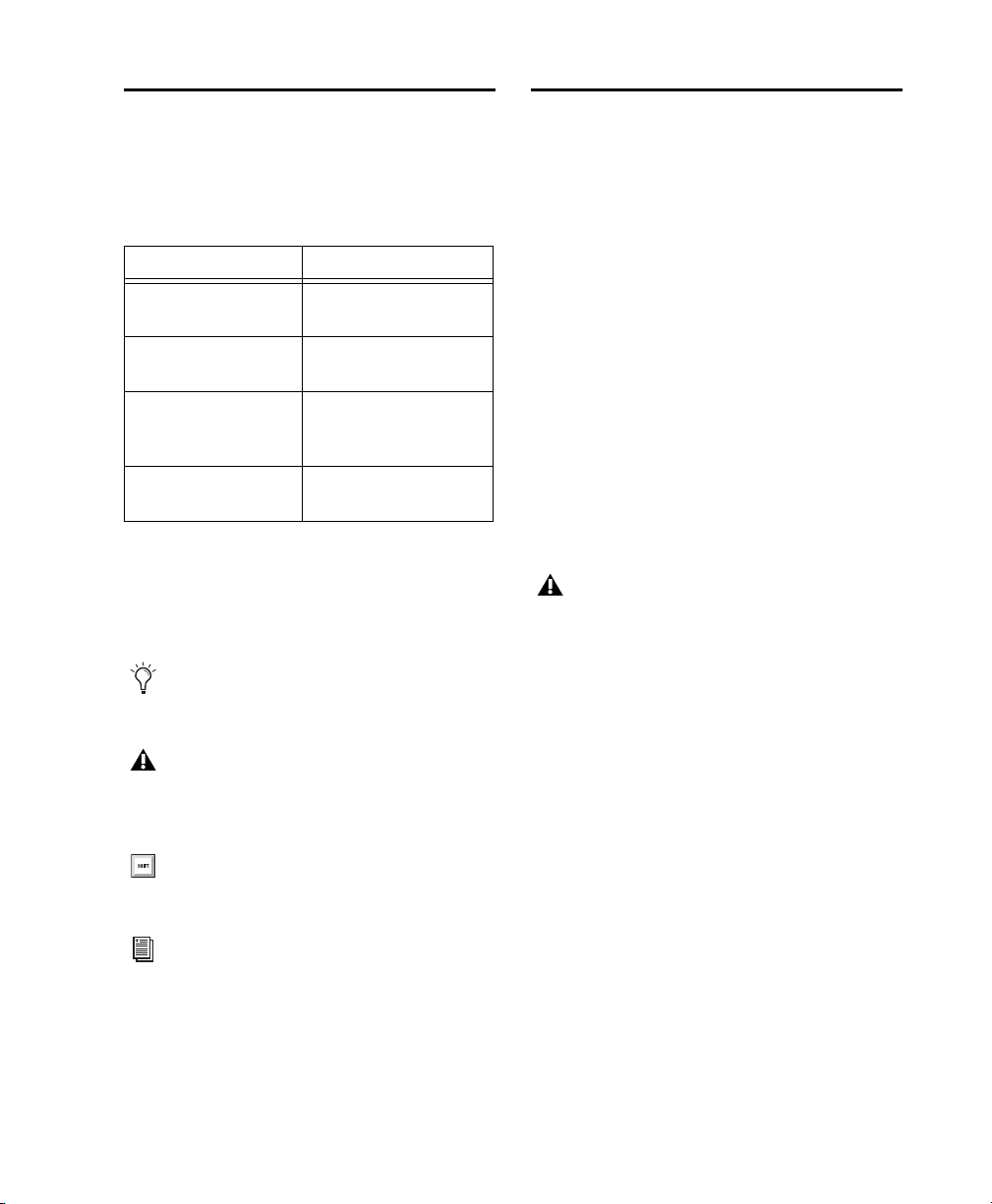
Pro Tools documentation uses the following
conventions to indicate menu choices, keyboard
commands, and mouse commands:
Convention Action
File > Save Choose Save from the
Control+N Hold down the Control
Control-click Hold down the Control
Right-click Click with the right
The names of
Commands, Options, and Settings
File menu
key and press the N key
key and click the mouse
button
mouse button
that appear on-screen are in a different font.
The following symbols are used to highlight
important information:
User Tips are helpful hints for getting the
most from your Pro Tools system.
Important Notices include information that
could affect your Pro Tools session data or
the performance of your Pro Tools system.
Shortcuts show you useful keyboard or
mouse shortcuts.
To use Pro Tools plug-ins, you need the following:
•Any of the following systems:
• An Avid-qualified system running
Pro Tools or Pro Tools HD
• A qualified Avid VENUE system
(TDM only)
®
• A qualified Avid Media Composer
system
(AudioSuite and RTAS only)
• An Avid-qualified system and a third-party
software application that supports the
RTAS, TDM, or AudioSuite plug-in standards
• USB Smart Key (iLok), for plug-ins that can be
purchased or rented
The iLok USB Smart Key is not supplied
with plug-ins or software options. You can
use the one included with certain Pro Tools
systems (such as Pro Tools|HD-series systems), or purchase one separately.
Avid can only assure compatibility and provide
support for hardware and software it has tested
and approved.
For complete system requirements and a list of
Avid-qualified computers, operating systems,
hard drives, and third-party devices, visit:
www.avid.com/compatibility
Cross References point to related sections in
this guide and other Avid documentation.
Third-Party Plug-In Support
For information on third-party plug-ins for
Pro Tools and VENUE systems, please refer to
the documentation that came with your plug-in.
Chapter 1: Audio Plug-Ins Overview 7
Page 24

Contents of the Boxed Version of Your Plug-In
If you bought your plug-in as a boxed version, it
includes the following:
• Installation disc (for selected plug-ins)
• Activation Card with an Activation Code
for authorizing plug-ins with an iLok USB
Smart Key
About www.avid.com
The Avid website (www.avid.com) is your best
online source for information to help you get the
most out of your Pro Tools system. The following are just a few of the services and features
available.
Product Registration
online.
Register your purchase
Support and Downloads
Success (technical support); download software
updates and the latest online manuals; browse
the Compatibility documents for system requirements; search the online Knowledge Base
or join the worldwide Pro Tools community on
the User Conference.
Training and Education
courses available online or find out how you can
learn in a classroom setting at a certified
Pro Tools training center.
Products and Developers
products; download demo software or learn
about our Development Partners and their plugins, applications, and hardware.
News and Events
or sign up for a Pro Tools demo.
Contact Avid Customer
Study on your own using
Learn about Avid
Get the latest news from Avid
Audio Plug-Ins Guide8
Page 25
Chapter 2: Installing Plug-Ins
Installers for your plug-ins can be downloaded
from the Avid store (store.avid.com) or can be
found on the plug-in installer disc (included
boxed versions of selected plug-ins).
An installer may also be available on the
Pro Tools installer disc or on a software bundle
installer disc.
Free Pro Tools Plug-Ins
A suite of free Avid audio effects and virtual instruments plug-ins are included with Pro Tools.
Avid Effects
that can be installed with Pro Tools.
Avid Virtual Instruments
strument plug-ins (including 4.4 GB of sample
content) included on the Pro Tools installation
disc and also available separately online.
A set of free audio effects plug-ins
A set of free virtual in-
For more information about installing the
Avid Effects plug-ins and the Avid Virtual
Instruments plug-ins, see the
stallation Guide
:
Pro Tools In-
Free VENUE Plug-Ins
VENUE-compatible plug-ins are pre-installed
on your VENUE system and are updated when
you update VENUE software. For more information about installing VENUE software, see the
documentation that came with your VENUE
system.
Some free Avid audio plug-ins can be downloaded from the Avid website (www.avid.com)
for use with VENUE systems, Avid
Media Composer, as well as other applications
that support AAX, AudioSuite, RTAS, or TDM
plug-in formats.
Updating Older Plug-Ins
Because plug-in installers contain the latest versions of the plug-ins, use them to update any
plug-ins you already own. When installing
Pro Tools, the Pro Tools installer automatically
updates the core Pro Tools plug-ins.
Be sure to use the most recent versions of
plug-ins. For more information, see the
Avid website (www.avid.com).
Using Pro T ools Plug-Ins with Avid Media Composer
The plug-in installation, authorization, and uninstallation processes when using Pro Tools
plug-ins with Media Composer are the same as
in Pro Tools. For more information on using
Pro Tools plug-ins with Media Composer, see
“Installing Plug-Ins for Pro Tools” on page 10,
“Authorizing Paid Plug-Ins” on page 10, and
“Removing Plug-Ins for Pro Tools” on page 12.
Chapter 2: Installing Plug-Ins 9
Page 26
Installing Plug-Ins for Pro Tools
To install a plug-in:
1 Do one of the following:
• Download the installer for your computer
platform from the Avid website
(www.avid.com). After downloading,
you may need to uncompress the installer
(.SIT on Mac or .ZIP on Windows).
– or –
• Insert the installer disc that came with the
boxed version of your plug-in into your
computer.
2 Double-click the plug-in installer application.
3 Follow the on-screen instructions to complete
the installation.
4 When installation is complete, click Quit (Mac)
Finish (Windows).
or
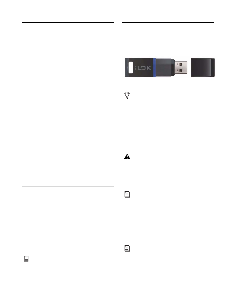
Authorizing Paid Plug-Ins
Pro Tools plug-ins are authorized using the iLok
USB Smart Key (iLok), manufactured by PACE
Anti-Piracy.
iLok USB Smart Key
Not all Pro Tools plug-ins require authorization. For example, no authorization is
required for the free plug-ins included with
Pro Tools.
An iLok can hold hundreds of licenses for all of
your iLok-enabled software. Once an iLok is authorized for a given piece of software, you can
use the iLok to authorize that software on any
computer.
When you open Pro Tools, you are prompted to
authorize your new plug-in (see “Using Pro
Tools Plug-Ins with Avid Media Composer” on
page 9).
Installing Plug-Ins for VENUE Systems
Installers for VENUE plug-ins can be downloaded from www.avid.com. After downloading,
the installer must be transferred to either a USB
drive or a CD-ROM. Plug-Ins can then be installed using a USB drive connected to the USB
ports on any VENUE system, or using a CDROM inserted into the CD-ROM drive available
on FOH Rack or Mix Rack.
For complete instructions on installing plugins for VENUE systems, see the documentation that came with your VENUE system.
Audio Plug-Ins Guide10
The iLok USB Smart Key is not supplied
with plug-ins or software options. You can
use the one included with certain Pro Tools
systems (such as Pro Tools|HD-series systems), or purchase one separately.
For more information, visit the iLok website
(www.iLok.com).
Authorizing Downloaded
Plug-Ins for Pro Tools
If you downloaded a plug-in from the Avid Store
(store.avid.com), you authorize it by downloading a license from iLok.com to an iLok.
For more information, visit the iLok website
(www.iLok.com).
Page 27

Authorizing Boxed Versions of
Plug-Ins for Pro Tools
Authorizing Plug-Ins on VENUE
Systems
If you purchased a boxed version of software, it
comes with an Activation Code (on the included
Activation Card).
To authorize a plug-in using an Activation Code:
1 If you do not have an iLok.com account, visit
www.iLok.com and sign up for an account.
2 Transfer the license for your plug-in to your
iLok.com account by doing the following:
• Visit www.avid.com/activation.
– and –
• Input your Activation Code (listed on your
Activation Card) and your iLok.com User
ID. Your iLok.com User ID is the name you
create for your iLok.com account.
3 Transfer the licenses from your iLok.com ac-
count to your iLok USB Smart Key by doing the
following:
• Insert the iLok into an available USB port
on your computer.
• Go to www.iLok.com and log in.
• Follow the on-screen instructions for transferring your licences to your iLok.
4 Launch Pro Tools.
5 If you have any installed unauthorized plug-
ins or software options, you are prompted to authorize them. Follow the on-screen instructions
to complete the authorization process.
After installing a plug-in on a VENUE system,
the system re-creates the list of available plugins. Whenever the racks initialize, the system
checks authorizations for all installed plug-ins.
If no previous authorization for a plug-in is recognized, you will be prompted to authorize the
the plug-in.
For complete instructions on authorizing
plug-ins for VENUE systems, see the
documentation that came with your VENUE
system.
VENUE supports challenge/response and iLok
USB Smart Key authorization, including pre-authorized iLoks and Activation Cards.
Challenge/Response
Challenge/response authorization is only valid for the VENUE system the
plug-in is currently installed on. Challenge/response codes can be communicated using any
computer with Internet access.
iLok USB Smart Key
Plug-Ins supporting web
authorizations through iLok.com can be authorized for your iLok USB Smart Key from any
computer with Internet access. This lets you
take your iLok and your plug-in authorizations
anywhere, to use plug-ins installed on any
system.
For more information, visit the iLok website
(www.iLok.com).
Chapter 2: Installing Plug-Ins 11
Page 28

Removing Plug-Ins for Pro Tools
Removing Plug-Ins f or VENUE Systems
If you need to remove a plug-in from your
Pro Tools system, follow the instructions for
your computer platform.
To remove a plug-in on Mac:
1 Locate and open the Plug-Ins folder on your
Startup drive, which will be in one of the following locations:
• Library/Application Support/
Digidesign/Plug-Ins
– or –
• Library/Application Support/Avid/Audio/
Plug-Ins
2 Do one of the following:
• Drag the plug-in to the Trash and empty the
Tra sh .
– or –
• Drag the plug-in to the Plug-Ins (Unused)
folder.
To remove a plug-in in Windows:
1 Choose Start > Control Panel.
Plug-Ins installed on VENUE systems can be
disabled, uninstalled, or deleted. A plug-in that
has been disabled or uninstalled (but not deleted) can be reinstalled without the CD-ROM or
USB drive containing the plug-in installers. Deleted plug-ins, however, must be reinstalled
from installers located on either a USB drive or a
CD-ROM.
For complete instructions on uninstalling
plug-ins for VENUE systems, see the
documentation that came with your VENUE
system.
2 Click Programs and Features.
3 Select the plug-in from the list of installed ap-
plications.
4 Click Uninstall.
5 Follow the on-screen instructions to remove
the plug-in.
Audio Plug-Ins Guide12
Page 29

Part II: EQ Plug-Ins
Page 30

Page 31

Chapter 3: AIR Kill EQ
AIR Kill EQ is an RTAS EQ plug-in.
Use the Kill EQ plug-in to zap out the Low, Mid,
or High broadband frequency range from an audio signal. This is a popular effect with DJs and
is commonly used in electronic music production (especially in dance music).
Kill EQ plug-in window
Kill EQ Controls
The Kill EQ plug-in provides a variety of controls for adjusting plug-in parameters.
Kill Switches
The High, Mid, and Low switches toggle their respective frequency bands on and off.
Gain
The Low, Mid, and High gain knobs control the
relative volume of the three frequency bands.
Freq
The Low and High freq controls set the crossover frequencies of the low and high pass filters.
The Sweep control changes both the low and
high-band cutoff frequencies simultaneously.
When the high and low bands are killed, manipulating this control creates a swept bandpass filter effect.
Output
The Output control sets the final output volume.
Chapter 3: AIR Kill EQ 15
Page 32

Audio Plug-Ins Guide16
Page 33

Chapter 4: EQ III
The EQ III plug-in provides a high-quality
7 Band, 2–4 Band, or 1 Band EQ for adjusting
the frequency spectrum of audio material.
EQ III is available in the following formats:
• 7 Band: TDM, RTAS, and AudioSuite
•2–4Band: TDM and RTAS only
• 1 Band: TDM, RTAS, and AudioSuite
EQ III supports all Pro Tools session sample
rates: 192 kHz, 176.4 kHz, 96 kHz, 88.2 kHz,
48 kHz, and 44.1 kHz. EQ III operates as a
mono, multi-mono, or stereo plug-in.
EQ III can be operated from the following control surfaces:
• D-Command
•D-Control
• ProControl
•C|24
•Control|24
• Digi 003
• Digi 002
• Command|8
•EUCON
• Mackie HUI-compatible controllers
™
EQ III has a Frequency Graph display that shows
the response curve for the current EQ settings
on a two-dimensional graph of frequency and
gain. The frequency graph display also lets you
modify frequency, gain and Q settings for individual EQ bands by dragging their corresponding points in the graph.
By choosing from the 7 Band, 2–4 Band, or
1 Band versions of the EQ III plug-in, you can
use only the number of EQ bands you need for
each track, conserving DSP capacity on
Pro Tools|HD systems.
EQ III Configurations
The EQ III plug-in appears as three separate
choices in the plug-in insert pop-up menu and
in the AudioSuite menu:
• 1 Band (“1-Band EQ 3”)
• 2–4 Band (“4-Band EQ 3”)
• 7 Band (“7-Band EQ 3”)
Chapter 4: EQ III 17
Page 34

1Band EQ
The 1 Band EQ is available in TDM, RTAS, and
AudioSuite formats.
The 1 Band EQ has its own window, with six selectable filter types.
1 Band EQ window
7 Band EQ and 2–4 Band EQ
Adjusting EQ III Controls
You can adjust the EQ III plug-in controls using
different methods.
Dragging Plug-In Controls
The rotary controls on the EQ III plug-in can be
adjusted by dragging over them horizontally or
vertically. Dragging up or to the right increments the control. Dragging down or to the left
decrements the control.
Dragging a plug-in control in EQ III
The 7 Band EQ is available in TDM, RTAS, and
AudioSuite formats. The 2–4 Band EQ is available in TDM and RTAS formats only.
The 7 Band EQ and the 2–4 Band EQ share the
same window and identical controls, but with
the 2–4 Band EQ, a limited number of the seven
available bands can be active at the same time.
7 Band EQ and 2–4 Band EQ window
Typing Control Values
You can enter control values directly by clicking
in the corresponding text box, typing a value,
and pressing Enter (Windows) or Return (Mac).
Typing a control value
Inverting Filter Gain
(Peak EQ Bands Only)
Gain values can be inverted on any Peak EQ
band by Shift-clicking its control dot in the Frequency Graph display, or its Gain knob in the
plug-in window. This changes a gain boost to a
cut (+9 to –9) or a gain cut to a boost (–9 to +9).
Gain values cannot be inverted on Notch,
High Pass, Low Pass, or shelving bands.
Audio Plug-Ins Guide18
Page 35

Dragging in the Frequency
Graph Display
Resetting EQ III Controls to
Default Values
You can adjust the following by dragging the
control points directly in the Frequency Graph
display:
Frequency
Dragging a control point to the right
increases the Frequency setting. Dragging a control point to the left decreases the Frequency
setting.
Gain
Dragging a control point up increases the
Gain setting. Dragging a control point down decreases the Gain setting.
Q
Start-dragging (Windows) or Control-dragging (Mac) a control point up increases the Q
setting. Start-dragging (Windows) or Controldragging (Mac) a control point down decreases
the Q setting.
You can reset any on-screen control to its default value by Alt-clicking (Windows) or Option-clicking (Mac OS) directly on the control or
on its corresponding text box.
Using EQ III in Band-Pass Mode
You can temporarily set any EQ III control to
Band-Pass monitoring mode. Band-Pass mode
cuts monitoring frequencies above and below
the Frequency setting, leaving a narrow band of
mid-range frequencies. It is especially useful for
adjusting limited bandwidth in order to solo and
fine-tune each individual filter before reverting
the control to notch filter or peaking filter type
operations.
Band-Pass mode does not affect EQ III Gain
controls.
To switch an EQ III control to Band-Pass mode:
Hold Start+Shift (Windows) or Control+Shift
(Mac), and drag any rotary control or control
point horizontally or vertically.
Dragging a control point in the Frequency Graph
display
Adjusting Controls with Fine
Resolution
Controls and control points can be adjusted with
fine resolution by holding the Command key
(Mac) or the Control key (Windows) while adjusting the control.
EQ III interactive graph displaying Band-Pass mode
Chapter 4: EQ III 19
Page 36

When monitoring in Band-Pass mode, the Fre-
Input
Output Gain
Input and Output Meters
Gain
Input
Polarity
Clip
Indicators
Control
Control
Control
quency and Q controls function differently.
Frequency
Sets the frequency above and below
which other frequencies are cut off, leaving a
narrow band of mid-range frequencies.
Q
Sets the width of the narrow band of midrange frequencies centered around the Frequency setting.
To switch an EQ III control out of Band-Pass mode:
Release Start+Shift (Windows) or Con-
trol+Shift (Mac).
Controlling EQ III from a Control
Surface
EQ III can be controlled from any supported
control surface, including our D-Control, DCommand, ProControl, C|24, 003, Digi 002, or
Command|8. Refer to the guide that came with
the control surface for details.
EQ III I/O Controls
Certain Input and Output controls are found on
all EQ III configurations, except where noted
otherwise.
I/O controls and meters for 7 Band EQ and
2–4 Band EQ (top) and 1 Band EQ (bottom)
Input Gain Control
Audio Plug-Ins Guide20
The Input Gain control sets the input gain of the
plug-in before EQ processing, letting you make
up gain or prevent clipping at the plug-in input
stage.
Output Gain Control
(7 Band EQ and 2–4 Band EQ Only)
The Output Gain control sets the output gain after EQ processing, letting you make up gain or
prevent clipping on the channel where the plugin is being used.
Page 37

Input Polarity Control
The Input Polarity button inverts the polarity of
the input signal, to help compensate for phase
anomalies occurring in multi-microphone environments, or because of mis-wired balanced
connections.
Input and Output Meters
(7 Band EQ and 2–4 Band EQ Only)
The plasma-style Input and Output meters show
peak signal levels before and after EQ processing, and indicate them as follows:
Green
Indicates nominal levels
Yellow
Indicates pre-clipping levels, starting at
–6 dB below full scale
Red
Indicates full scale levels (clipping)
When using the stereo version of EQ III, the Input and Output meters display the sum of the
left and right channels.
The Clip indicators at the far right of each meter
indicate clipping at the input or output stage of
the plug-in. Clip indicators can be cleared by
clicking the indicator.
EQ III EQ Band Controls
Individual EQ bands on each EQ III configuration have a combination of controls.
EQ Type Selector
On the 1 Band EQ, the EQ Type selector lets you
choose any one of six available filter types:
High Pass, Notch, High Shelf, Low Shelf, Peak,
and Low Pass.
On the 7 Band EQ and the 2–4 Band EQ, the
HPF, LPF, LF, and HF sections have EQ Type selectors to toggle between the two available filter
types in each section.
EQ Type Selectors
Chapter 4: EQ III 21
Page 38

Band Enable Button
(7 Band EQ and 2–4 Band EQ Only)
The Band Enable button on each EQ band toggles the corresponding band in and out of circuit. When a Band Enable button is highlighted,
the band is in circuit. When a Band Enable button is dark gray, the band is bypassed and available for activation. On the 2–4 Band EQ, when a
Band Enable button is light gray, the band is bypassed and unavailable.
Frequency Control
Each EQ band has a Frequency control that sets
the center frequency (Peak, Shelf and Notch
EQs) or the cutoff frequency (High Pass and
Low Pass filters) for that band.
Frequency control
Q Control
Band Enable button
Band Gain Control
Each Peak and Shelf EQ band has a Gain control
for boosting or cutting the corresponding frequencies. Gain controls are not used on
High Pass, Low Pass, or Notch filters.
Band Gain control
Peak and Notch
On Peak and Notch bands, the Q
control changes the width of the EQ band.
Higher Q values represent narrower bandwidths.
Lower Q values represent wider bandwidths.
Shelf
On Shelf bands, the Q control changes the
Q of the shelving filter. Higher Q values represent steeper shelving curves. Lower Q values
represent broader shelving curves.
Band Pass
On High Pass and Low Pass bands,
the Q control lets you select from any of the following Slope values: 6 dB, 12 dB, 18 dB, or 24 dB
per octave.
Q control
Audio Plug-Ins Guide22
Page 39

EQ III Frequency Graph Display
High Pass
control dot
Low Mid
control dot
High Mid
control dot
Low Pass
control dot
(gray) (brown) (green) (gray)
Low
control dot
(red)
Mid
control dot
(yellow)
High
control dot
(blue)
Frequency
response
curve
(7 Band EQ and 2–4 Band EQ Only)
The Frequency Graph display in the 7 Band EQ and the 2–4 Band EQ shows a color-coded control dot
that corresponds to the color of the Gain control for each band. The filter shape of each band is similarly color-coded. The white frequency response curve shows the contribution of each of the enabled
filters to the overall EQ curve.
Frequency Graph display for the 7 Band EQ
Chapter 4: EQ III 23
Page 40

7 Band EQ III
High Pass/
Low Pass/
Low
Shelf/Peak
Mid
Peak
High
Shelf/Peak
Low Mid
Peak
High Mid
Peak
Input/Output Level meters
Frequency Graph
Display
Input/Output Level
and
Polarity controls
Low Notch
High Notch
The 7 Band EQ has the following available bands: High Pass/Low Notch, Low Pass/High Notch,
Low Shelf/Low Peak, Low Mid Peak, Mid Peak, High Mid Peak, and High Shelf/High Peak.
All seven bands are available for simultaneous use. In the factory default setting, the High Pass/Low
Notch and Low Pass/High Notch bands are out of circuit, the Low Shelf and High Shelf bands are selected and in circuit, and the Low Mid Peak, Mid Peak, High Mid Peak bands are in circuit.
7 Band EQ and 2–4 Band EQ window
Audio Plug-Ins Guide24
Page 41

7 Band EQ III High Pass/Low
High Pass Filter
button
Frequency
control
Slope
control
Frequency
controlQcontrol
Band
Enable
button
Low Notch EQ
button
Band
Enable
button
Low Pass Filter
button
Frequency
control
Slope
control
Frequency
controlQcontrol
Band
Enable
button
High Notch EQ
button
Band
Enable
button
Notch
7 Band EQ III Low Pass/High
Notch
The High Pass/Notch band is switchable between high pass filter and notch EQ functions.
By default, this band is set to High Pass Filter.
High Pass Filter
Attenuates all frequencies below the Frequency setting at the selected slope
while letting all frequencies above pass through.
Low Notch EQ
Attenuates a narrow band of frequencies centered around the Frequency setting. The width of the attenuated band is determined by the Q setting.
The Low Pass/Notch band is switchable between
low pass filter and notch EQ functions. By default, this band is set to Low Pass Filter.
Low Pass Filter
Attenuates all frequencies above
the Frequency setting at the selected slope while
letting all frequencies below pass through.
High Notch EQ
Attenuates a narrow band of frequencies centered around the Frequency setting. The width of the attenuated band is determined by the Q setting.
High Pass filter (left) and Low Notch EQ (right)
The High Pass and Low Notch EQ controls and
their corresponding graph elements are displayed on-screen in gray. The following control
values are available:
Control Value
Frequency Range 20 Hz to 8 kHz
Frequency Default 20 Hz
HPF Slope Values 6, 12, 18, or 24 dB/oct
Low Notch Q Range 0.1 to 10.0
Low Notch Q Default 1.0
Low Pass filter (left) and High Notch EQ (right)
The Low Pass and High Notch EQ controls and
their corresponding graph elements are displayed on-screen in gray. The following control
values are available:
Control Value
Frequency Range 20 Hz to 8 kHz
Frequency Default 20 Hz
HPF Slope Values 6, 12, 18, or 24 dB/oct
Low Notch Q Range 0.1 to 10.0
Low Notch Q Default 1.0
Chapter 4: EQ III 25
Page 42

7 Band EQ III Low Shelf/Low
Low Shelf EQ
button
Frequency
control
Band
Enable
button
Gain
control
Q
control
Low Peak EQ
button
Frequency
control
Band
Enable
button
Gain
control
Q
control
Peak
The Low Shelf/Peak band is switchable between
low shelf EQ and low peak EQ functions. By default, this band is set to Low Shelf.
Low Shelf EQ
below the Frequency setting. The amount of
boost or cut is determined by the Gain setting.
The Q setting determines the shape of the shelving curve.
Low Peak EQ
cies centered around the Frequency setting. The
width of the affected band is determined by the
Q setting.
Boosts or cuts frequencies at and
Boosts or cuts a band of frequen-
The Low Shelf and Low Peak Gain controls and
their corresponding graph elements are displayed on-screen in red. The following control
values are available:
Control Value
Frequency Range 20 Hz to 500 Hz
Frequency Default 100 Hz
Low Shelf Q Range 0.1 to 2.0
Low Peak Q Range 0.1 to 10.0
Q Default 1.0
Low Shelf Gain Range –12 dB to +12 dB
Low Peak Gain Range –18 dB to +18 dB
Low Shelf EQ (left) and Low Peak EQ (right)
Audio Plug-Ins Guide26
Page 43

7 Band EQ III Low Mid Peak
Frequency
control
Band
Enable
button
Gain
control
Q
control
Frequency
control
Band
Enable
button
Gain
control
Q
control
7 Band EQ III Mid Peak
The Low Mid Peak band boosts or cuts frequencies centered around the Frequency setting. The
wi dt h o f t he ba nd is de ter mi ne d b y t he Q s et ti ng .
Low Mid Peak EQ
The Low Mid Gain control and its corresponding
graph elements are displayed on-screen in
brown. The following control values are available:
Control Value
Frequency Range 40 Hz to 1 kHz
Frequency Default 200 Hz
Low Mid Peak Q
Range
Low Mid Peak Q
Default
0.1 to 10.0
1.0
The Mid Peak band boosts or cuts frequencies
centered around the Frequency setting. The
width of the band is determined by the Q setting.
Mid Peak EQ
The Mid Gain control and its corresponding
graph elements are displayed on-screen in yellow.
Control Value
Frequency Range 125 Hz to 8 kHz
Frequency Default 1 kHz
Mid Peak Q Range 0.1 to 10.0
Mid Peak Q Default 1.0
Mid Peak Gain Range –18 dB to +18 dB
Low Mid Peak Gain
Range
–18 dB to +18 dB
Chapter 4: EQ III 27
Page 44

7 Band EQ III High Mid Peak
Frequency
control
Band
Enable
button
Gain
control
Q
control
High Shelf EQ
button
Frequency
control
Band
Enable
button
Gain
control
Q
control
High Peak EQ
button
Frequency
control
Band
Enable
button
Gain
control
Q
control
The High Mid Peak band boosts or cuts frequencies centered around the Frequency setting. The
width of the band is determined by the Q setting.
7 Band EQ III High Shelf/High
Peak
The High Shelf/Peak band is switchable between
high shelf EQ and high peak EQ functions. By
default, this band is set to High Shelf.
High Mid Peak EQ
The High Mid Gain control and its corresponding graph elements are displayed on-screen in
green. The following controls are available:
Control Value
Frequency Range 200 Hz to 18 kHz
Frequency Default 2 kHz
Mid Peak Q Range 0.1 to 10.0
Mid Peak Q Default 1.0
Mid Peak Gain Range –18 dB to +18 dB
High Shelf EQ
Boosts or cuts frequencies at and
above the Frequency setting. The amount of
boost or cut is determined by the Gain setting.
The Q setting determines the shape of the shelving curve.
High Peak EQ
Boosts or cuts a band of frequencies centered around the Frequency setting. The
width of the affected band is determined by the
Q setting.
Audio Plug-Ins Guide28
High Shelf EQ (left) and High Peak EQ (right)
Page 45

The High Shelf and High Peak Gain controls and
their corresponding graph elements are displayed on-screen in blue. The following control
values are available:
Control Value
Frequency Range 1.8 kHz to 20 kHz
Frequency Default 6 kHz
High Shelf Q Range 0.1 to 2.0
High Peak Q Range 0.1 to 10.0
Q Default 1.0
High Shelf Gain
Range
High Peak Gain
Range
–12 dB to +12 dB
–18 dB to +18 dB
2–4 Band EQ III
The 2–4 Band EQ uses the same plug-in window
as the 7 Band EQ, but on the 2–4 Band EQ, but a
limited number of the seven available bands can
be active at the same time.
Filter Usage with 2–4 Band
EQ III
With a 2–4 Band EQ, a maximum of four filters
may be active simultaneously, with each of the
five Pea k ba nds (Low Shelf/Peak, Low Mid Peak,
Mid Peak, High Mid Peak and High Shelf/Peak)
counting as one filter. Each of the Band-pass and
Notch filters (High Pass, Low Notch, Low Pass
and High Notch) counts as two filters.
When any combination of these filter types uses
the four-filter maximum on the 2–4 Band EQ,
the remaining bands become unavailable. This
is indicated by the Band Enable buttons turning
light gray. When filters become available again,
the Band Enable button on inactive bands turns
dark gray.
In the factory default setting, the High Pass/Low
Notch, Low Pass/High Notch and Mid Peak
bands are out of circuit, the Low Shelf and High
Shelf bands are selected and in circuit, and the
Low Mid Peak and High Mid Peak bands are in
circuit.
For Pro Tools HD, using a 2–4 Band EQ instead of a 7 Band EQ saves DSP resources.
Chapter 4: EQ III 29
Page 46

Switching Between the
Frequency
response
curve
Control dot
Frequency Graph
display
EQ Type
selector
Gain, Freq and
Input Level and
Polarity controls
Q controls
2–4 Band EQ and 7 Band EQ III
When you switch an existing EQ III plug-in between the 2–4 Band and 7 Band versions, or
when you import settings between versions, the
change is subject to the following conditions:
Changing from 2–4 Band to 7 Band
After switching from a 2–4 band EQ to a 7 Band
EQ, or importing settings from a 2–4 Band EQ,
all control settings from the 2–4 Band EQ are
preserved, and the bands in the 7 Band EQ inherit their enabled or bypassed state from the
2–4 Band plug-in.
Additional EQ bands can then be enabled to add
them to the settings inherited from the
2–4 Band plug-in.
Changing from 7 Band to 2–4 Band
After switching from a 7 band EQ to a 2–4 Band
EQ, or importing settings from a 7 Band EQ, all
control settings from the 7 Band EQ are preserved in the 2–4 Band EQ, but all bands are
placed in a bypassed state.
1 Band EQ III
The Frequency Graph display in the 1 Band EQ
shows a control dot that indicates the center frequency (Peak, Shelf and Notch Filters) or the
cutoff frequency (High Pass and Low Pass filters) for the currently selected filter type.
Frequency Graph display
Bands can then be enabled manually, up to the
2–4 Band EQ four-filter limit.
Audio Plug-Ins Guide30
1 Band EQ window
The 1 Band EQ may be set to any one of six EQ
types: High Pass, Notch, High Shelf, Low Shelf,
Peak, and Low Pass, by clicking the corresponding icon in the EQ Type selector.
Page 47

Band Controls
Notch Filter
The individual EQ types have some combination
of the following controls, as noted below.
Control Value
Frequency Range (All) 20 Hz to 20 kHz
Frequency Default (All) 1 kHz
Q Range (Low/High Shelf) 0.1 to 2.0
Q Range (Peak/Notch) 0.1 to 10.0
Q Default (All) 1.0
Gain Range (Low/High Shelf) –12 dB to +12 dB
High Peak Gain Range –18 dB to +18 dB
1 Band EQ III Types
High Pass Filter
The High Pass filter attenuates all frequencies
below the Frequency setting at the selected rate
(6 dB, 12 dB, 18 dB, or 24 dB per octave) while
letting all frequencies above pass through. No
gain control is available for this filter type.
The Notch Filter attenuates a narrow band of
frequencies centered around the Frequency setting. No gain control is available for this EQ
type. The width of the attenuated band is determined by the Q setting.
1 Band EQ set to Notch Filter
High Shelf EQ
The High Shelf EQ boosts or cuts frequencies at
and above the Frequency setting. The amount of
boost or cut is determined by the Gain setting.
The Q setting determines the shape of the shelving curve.
1 Band EQ set to High Pass Filter
1 Band EQ set to High Shelf EQ
Chapter 4: EQ III 31
Page 48

Low Shelf EQ
Low Pass Filter
The Low Shelf EQ boosts or cuts frequencies at
and below the Frequency setting. The amount of
boost or cut is determined by the Gain setting.
The Q setting determines the shape of the shelving curve.
1 Band EQ set to Low Shelf EQ
Peak EQ
The Peak EQ boosts or cuts a band of frequencies centered around the Frequency setting. The
width of the affected band is determined by the
Q setting.
The Low Pass filter attenuates all frequencies
above the cutoff frequency setting at the selected rate (6 dB, 12 dB, 18 dB, or 24 dB per octave) while letting all frequencies below pass
through. No gain control is available for this filter type.
1 Band EQ set to Low Pass Filter
1 Band EQ set to Peak EQ
Audio Plug-Ins Guide32
Page 49

Chapter 5: JOEMEEK VC5 Meequalizer
The JOEMEEK VC5 Meequalizer is an EQ
plug-in that is available in TDM, RTAS, and AudioSuite formats and offers simple controls with
incredibly warm, musical results.
JOEMEEK Meequalizer VC5 EQ
How the Meequalizer Works
Picture this: drums in the spare bedroom. Microphones, cables, and recording gear strewn
about the living room. A familiar scene—especially to legendary producer Joe Meek in 1962 as
he prepared to record yet another chart topping
hit.
Among countless other achievements, Joe Meek
built custom gear to get the sounds in his head
onto tape. One device was a treble and bass circuit with a sweepable mid control, built into a
tiny tobacco tin. The Meequalizer VC5 virtually
recreates the exact circuitry used by Joe Meek.
JOEMEEK Meequalizer Controls
Operation of the Meequalizer is dead simple,
and that’s the whole point.
Bass
The Bass control adjusts low frequencies
±11.
Mid and Mid Freq
trols allow you to adjust mid frequencies, from
500Hz to 3.5KHz, ±11.
Treble
The Treble control adjusts high frequen-
cies ±11.
Gain
The Gain control allows you to adjust the
output level ±11.
JOEMEEK Meezqualizer Tips and Tricks
Twelve O’Click
Alt-click (Windows) or Option-click (Mac) any
knob to reset any knob to its unity position
quickly.
The Mid and Mid Freq con-
Chapter 5: JOEMEEK VC5 Meequalizer 33
Page 50

Audio Plug-Ins Guide34
Page 51

Chapter 6: Pultec Plug-Ins
Pultec plug-ins are a set of EQ plug-ins that are
available TDM, RTAS, and AudioSuite formats.
The following plug-ins are included:
• Pultec EQP-1A (see “Pultec EQP-1A” on
page 35)
• Pultec EQH-2 (see “Pultec EQH-2” on
page 36)
• Pultec MEQ-5 (see “Pultec MEQ-5” on
page 37)
Pultec EQP-1A
(TDM, RTAS, and AudioSuite)
The Pultec EQP-1A provides smooth, sweet EQ
and an extremely high quality tube audio signal
path. Use it on individual tracks, critical vocals,
or even across a stereo mix for mastering applications.
How Pultec EQP-1A Works
Built in the early 1960s, The Pultec EQP-1A offers gentle shelving program equalization on
bass and highs, and offers a variable bandwidth
peak boost control. A custom (and secret) filter
network provides all its equalization functionality. Quality transformers interface it to realworld studio equipment. And a clean and welldesigned tube amplifier provides a fixed amount
of make-up gain.
Pultec EQP-1A Controls
Low Frequency Section
using the Boost and Atten knobs and the Low
Frequency switch, located at the left side of the
unit. All low-frequency equalization is a gentle
shelving type, 6 dB per octave.
High Frequency Boost Section
high frequencies using the Bandwidth and Boost
knobs and the High Frequency switch.
High Frequency Attenuate Section
quencies using the Atten knob and the Atten Sel
switch located at the right side of the plug-in.
Adjust low frequencies
Boost mid and
Cut high fre-
Pultec EQP-1A
Chapter 6: Pultec Plug-Ins 35
Page 52

Pultec EQP-1A Tips and Tricks
Twelve O’Click
Alt-click (Windows) or Option-click (Mac) any
knob to reset it to its unity position.
“Q” and A
You may wonder why the Pultec EQP-1A has
separate knobs for boost and cut. The short answer is that they connect to different circuitry in
the unit.
You can use the “extra” knob to your advantage.
Because the filters are not phase perfect, a Boost
setting of 3 and an Atten setting of 3 can make a
huge difference, even though a frequency plot
wouldn’t show much difference in tone. You’re
hearing the phase shift, not the tone shift.
Our ears of very sensitive to phase, and using the
two knobs together, you can adjust phase at the
low end while also making tonal adjustments.
On the high end, you can set Boost to 10k and
Atten to 10k, then adjust Boost and Atten simultaneously. However, because Boost is a peak
equalizer and Atten is a shelving equalizer, the
results are much different, and you don’t get independent control of phase.
“Q” and Boost
In the high frequency boost section, the Bandwidth and Boost controls affect one another.
This is different from modern equalizers, where
adjusting Q typically doesn’t affect the amount
of equalization applied.
Use caution, because the Sharp bandwidth setting results in up to 10 dB higher output than
Broad bandwidth at maximum Boost, just like
on the original. But don’t feel like you’re getting
cheated. Here at Bomb Factory, we consider
anything that encourages very careful and infrequent use of peaky boosts to be a Very Good
Thing.
Pultec EQH-2
(TDM, RTAS, and AudioSuite)
The Pultec EQH-2 is a program equalizer similar
to the Pultec EQP-1A. It is designed to provide
smooth equalization across final mixes or individual tracks.
Pultec EQH-2
How Pultec EQH-2 Works
The Pultec EQH-2 offers three equalization sections: low frequency boost and attenuation,
midrange boost only, and 10k attenuation. Like
its EQP-1A sibling, it features high-quality
transformers and a tube gain stage. But unlike
the EQP-1A, the tube stage in the EQH-2 is a
push-pull design. As a result, the EQH-2 offers a
beefier tone.
Audio Plug-Ins Guide36
Page 53

Pultec EQH-2 Controls
Pultec MEQ-5 Controls
Low Frequency Section
Adjust low frequencies
using the top row of Boost and Atten knobs and
the CPS (cycles per second) switch. All low-frequency equalization is a gentle shelving type,
6 dB per octave.
High Frequency Boost Section
Boost mid and
high frequencies using the KCS (kilocycles per
second) and Boost knobs on the second row.
High Frequency Attenuate Section
Cut high frequencies using the 10k Atten knob located at the
right side of the plug-in.
Pultec EQH-2 Tips and Tricks
Alt-click (Windows) or Option-click (Mac) any
knob to reset it to its unity position.
Pultec MEQ-5
(TDM, RTAS, and AudioSuite)
The Pultec MEQ-5 is the most unique equalizer
in the Pultec family. It is particularly useful on
individual tracks during mixdown.
The Pultec MEQ-5 offers three equalization sections: low frequency boost, mid frequency
boost, and wide-range attenuation. Like all
Pultecs, it features quality transformers and a
tube gain stage.
How Pultec MEQ-5 is Used
Low Frequency Peak
Boost low frequencies
(200, 300, 500, 700, 1000 Hz) using the upper
left controls.
Mid Frequency Peak
Boost mid-frequencies
(1.5k, 2k, 3k, 4k, 5k) using the controls at the
upper right.
Wide-Range Dip
Cut frequencies using Dip con-
trols on the bottom row.
Pultec MEQ-5 Tips and Tricks
Guitars
Have multiple guitars that sound like mush in
the mix? The Pultec MEQ-5 is a classic tool for
achieving amazing guitar blends. Try boosting
one guitar and cutting another to achieve an octave of separation. For example, cut one guitar
using 1.5 (1500 Hz) Dip, then boost the other using 3 (3000 Hz) Peak. View the matched pairs of
presets (Guitar 1A and 1B, 2A and 2B, etc.) for
further examples of this technique.
Pultec MEQ-5
Twelve O’Click
Alt-click (Windows) or Option-click (Mac) any
knob to reset it to its unity position.
Chapter 6: Pultec Plug-Ins 37
Page 54

Audio Plug-Ins Guide38
Page 55

Part III: Dynamics Plug-Ins
Page 56

Page 57

Chapter 7: BF-2A
The BF-2A is a vintage-style compressor plug-in
that is available in TDM, RTAS, and AudioSuite
formats.
Meticulously crafted to capture every nuance of
the legendary LA-2A tube studio compressor,
the Bomb Factory BF-2A provides the most authentic vintage compression sound available.
BF-2A
How BF-2A Works
Designed and manufactured in the early 1960s,
the LA-2A achieved wide acclaim for its smooth
compression action and extremely high quality
audio signal path.
Originally designed as a limiter for broadcast
audio, a Comp/Limit switch was added to LA-2A
compressors after serial number 572. The subsequent addition of a Comp (Compress) setting
made the LA-2A even more popular for use in
audio production. However, the switch was inconve nie ntly locat ed on the back of th e uni t nex t
to the terminal strips and tube sockets in the
original version. In the BF-2A plug-in, the
switch has been placed on the front panel, where
you can make better use of it.
The heart of the LA-2A is its patented T4B ElectroOptical Attenuator, which provides the compression action. The T4B consists of a photoconductive cell, which changes resistance when
light strikes it. It is attached to an electro-luminescent panel, which produces light in response
to voltage. Audio (voltage) is applied to the light
source, and what happens as the audio converts
to light and back to voltage gives the LA-2A its
unique compression action. (Yes, the Bomb Factory BF-2A preserves all the subtle characteristics of this unique electronic circuit.) After compression, gain brings the signal back to its
original level. The LA-2A’s gain comes from a
tube amplifier, which imparts further character
to the tone. In fact, it’s common to see engineers
using the LA-2A simply as a line amp, without
any compression applied to the signal.
One beautiful side effect of the LA-2A’s elegant
design is that it’s easy to hear the compression
action. When the BF-2A’s two knobs are set
properly, you know you got it right. It’s a great
unit for learning the art of compression!
Chapter 7: BF-2A 41
Page 58

BF-2A Controls
The Peak Reduction and Gain controls combine
with the Comp/Limit switch to determine the
amount and sound of the compression. The following controls and meters are provided:
Gain
Gain provides makeup gain to bring the
signal back after passing through peak reduction.
Peak Reduction
amount of signal entering the side-chain, which
in turn affects the amount of compression and
the threshold. The more Peak Reduction you
dial in, the more “squashed” the sound. Too little peak reduction and you will not hear any
compression action; too much and the sound becomes muffled and dead sounding.
Comp/Lim
compression ratio. The common setting for audio production is Comp, which provides a maximum compression ratio of approximately 3:1.
In Limit mode, the unit behaves more like a
broadcast limiter, with a higher threshold and
compression ratio of approximately 12:1.
Peak Reduction controls the
The Comp/Limit switch affects the
Using the BF-2A Side-Chain
Filter
The BF-2A provides an extra parameter, a sidechain filter, that does not have a control on the
plug-in interface, but that can be accessed onscreen through Pro Tools automation controls.
In addition, the side-chain filter can be adjusted
directly from any supported control surface.
This side-chain filter reproduces the effect of an
adjustable resistor on the back panel of the
LA-2A. This control cuts the low frequencies
from the side-chain, or control signal, that determines the amount of gain reduction applied
by the compressor.
By increasing the value of the side-chain filter,
you filter out frequencies below 250 Hz from the
control signal, and decrease their effect on gain
reduction.
A setting of zero means that the filter is not
applied to the side chain signal.
A setting of 100 means that all frequencies be-
low 250 Hz are filtered out of the side chain signal.
Meter
Both Gain Reduction and Output metering are provided. The Meter knob operates as
follows:
• When set to Gain Reduction, the meter needle moves backward from 0 to show the
amount of compression being applied to the
signal in dB.
• Whe set to Output, the needle indicates the
output level of the signal. The meter is calibrated with 0 VU indicating –18 dBFS.
Audio Plug-Ins Guide42
To access the side-chain filter on-screen:
1 Click the Plug-In Automation button in the
Plug-In window to open the Automation Enable
window.
2 In the list of controls at the left, click to select
Side-Chain Filter and click
Add (or, just double-
click the desired control in the list).
3 Click OK to close the plug-in automation win-
dow.
Page 59

4 In the Edit window, do one of the following:
• Click the Track View selector and select
Side-Chain Filter from the BF-2A submenu.
– or –
• Reveal an Automation lane for the track,
click the Automation Type selector and select Side-Chain Filter from the BF-2A submenu.
5 Edit the breakpoint automation for the BF-2A
side-chain filter. Control range is from 0 (the default setting where no filtering is applied to the
side-chain) to 100% (maximum side-chain filtering).
To access the side-chain filter from a control
surface:
1 Focus the BF-2A plug-in on your control sur-
face.
2 Adjust the encoder or fader current targeting
the Side-Chain Filter parameter.
To automate your adjustments, be sure to
enable automation for that parameter as described above. See the Pro Tools Reference
Guide for complete track automation instructions.
BF-2A Tips and Tric ks
AudioSuite Processing
When using the AudioSuite version of the
BF-2A, be sure to select an auxillary side-chain
input (normally the track you’re processing).
The default is “None” and if you leave it set like
this, there is nothing feeding the detector and
you will not hear any compression action.
Line Amp
Turn the Peak Reduction knob full counterclockwise (off) and use the Gain control to increase the signal level. Although the BF-2A does
not compress the sound with these settings, it
still adds its unique character to the tone.
Feed the BF-2A into the BF76
Or vice versa. Glynn Johns (who has worked
with the Stones, the Who, and others) popularized the early ‘70s British trick of combining a
slower compressor with a faster one. The effect
can produce very interesting sounds! Try applying Peak Reduction using the BF-2A, then
squash the missed attacks using the faster BF76.
Chapter 7: BF-2A 43
Page 60

Audio Plug-Ins Guide44
Page 61

Chapter 8: BF-3A
The BF-3A is a vintage-style compressor plug-in
that is available in TDM, RTAS, and AudioSuite
formats.
Bomb Factory extends its award-winning Classic Compressors line with the BF-3A, based on
the classic LA-3A. A secret weapon of pros in the
know, the LA-3A adds a smoothness and sonic
texture that makes sounds jump right out of the
mix.
BF-3A
How BF-3A Works
Designed and manufactured in the late 1960s,
the original LA-3A shares many components in
common with the LA-2A compressor. Just like
the LA-2A, the heart of the LA-3A is the T4B
Electro-Optical Attenuator. This is a device that
converts audio to light and back and is largely
responsible for the compression character of the
unit.
While the LA-2A’s gain comes from a tube amplifier, the LA-3A's gain comes from a solidstate (transistor) amplifier. This gives the LA3A a solid midrange and more aggressive tone.
Other subtle modifications change the behavior
of the T4B, causing it to respond differently—
particularly in response to percussive material.
The LA-3A is famous for its unique sonic imprint on guitar, piano, vocals and drums. Because it's so easy to control, you'll be getting
classic tones in no time with the BF-3A.
BF-3A Controls
The Peak Reduction and Output Gain controls
combine with the Comp/Limit switch to determine the amount and sound of the compression.
The following controls and meters are provided:
Peak Reduction
amount of signal entering the side-chain. The
more Peak Reduction you dial in, the more
“squashed” and compressed the sound will be.
Too little peak reduction and you won’t hear any
compression action; too much and the sound becomes muffled and dead sounding.
Output Gain
to make the signal louder after passing through
the peak reduction.
Peak Reduction controls the
Output Gain provides makeup gain
Chapter 8: BF-3A 45
Page 62

Comp/Lim
The Comp/Limit switch affects the
compression ratio. The common setting for audio production is Comp, which provides a maximum compression ratio of approximately 3:1.
In Limit mode, the unit behaves more like a
broadcast limiter, with a higher threshold and
compression ratio of approximately 15:1.
Meter
Both Gain Reduction and Output metering are provided. The Meter knob operates as
follows:
• When set to Gain Reduction, the meter needle moves backward from 0 to show the
amount of compression being applied to the
signal in dB.
• When set to Output, the needle indicates
the output level of the signal. The meter is
calibrated with 0 VU indicating –18 dBFS.
BF-3A Tips and Tricks
AudioSuite Processing
When using the AudioSuite version of the
BF-3A, be sure to select an auxillary side-chain
input (normally the track you are processing).
The default is “None” and if you leave it set like
this, there is nothing feeding the detector and
you will not hear any compression action.
Line Amp
Turn the Peak Reduction knob full counterclockwise (off) and use the Gain control to increase the signal level. Although the BF-3A does
not compress the sound with these settings, it
still adds its unique character to the tone.
Audio Plug-Ins Guide46
Page 63

Chapter 9: BF76
The BF76 is a vintage-style compressor plug-in
that is available in TDM, RTAS, and AudioSuite
formats.
Modeled after the solid-state (transistor) 1176
studio compressor, the Bomb Factory BF76 preserves every sonic subtlety of this classic piece
of studio gear.
The Bomb Factory BF76
How the Bomb Factory BF76 Works
The 1176 Compressor, originally introduced in
the late 1970s, uses a FET (field-effect transistor). The 1176 also uses solid state amplification. The 1176 still provides an extremely high
quality audio signal path, but because of these
internal differences offers a much different
compression sound than other compressors.
Four selectable compression ratios are provided, along with controls allowing variable attack and release times.
Various explanations overheard in the control
room include “its 100:1 compression ratio!” or
equally adept quantitative analysis like “it
makes it super squishy sounding.” Now you can
enjoy this sound—previously only available to
super-serious-pro-engineers working in expensive pro recording studios—in the privacy of
your own cubicle.
Deep inside the 1176
BF76 Controls
BF76 provides the following controls:
Input
The Input control sets the input signal
level to the compressor, which, in the 1176 design, determines both the threshold and amount
of peak reduction.
Output
The Output control sets output level. Use
it to bring the signal back to unity after applying
gain reduction.
Attack and Release
trols set the attack and release times of the compressor. Full counterclockwise is slowest, and
full clockwise is fastest. Attack times vary between 0.4 milliseconds to 5.7 milliseconds. Release times vary between 0.06 and 1.1 seconds.
The Attack and Release con-
Chapter 9: BF76 47
Page 64

Ratio
The Ratio Push switches select the com-
pression ratio from 4:1 to 20:1.
Meter
The Meter Push switches affect the meter-
ing.
• GR shows the amount of gain reduction.
• –18 and –24 show the output level (calibrated so that 0VU indicates –18dB FS and
–24dB FS respectively).
• The “Off” switch turns off the meter.
BF76 Tips and Tricks
AudioSuite Processing
When using the AudioSuite version of the Bomb
Factory BF76, be sure to select a side-chain input (normally the track you are processing). The
default is “None” and if you leave it set like this,
there’s nothing feeding the detector and you
won’t hear any compression action.
Unexpected Visit from A&R Weevil Yields
Instant Hit Mix
A favorite feature on one megabuck mixing console is its stereo bus compressor. With the flick
of a switch, a punchy 8:1 compressor grabs the
current mix producing “instant radio hit.” Although Bomb Factory strongly disapproves of
anything which adds further chaos to the already opaque A&R decision-making process,
you may find that the Bomb Factory BF76 set to
8:1 ratio on a stereo mix provides a fast, easy alternate mix that can provide fresh ideas. It’s also
a handy way to make quick headphone submixes
when tracking overdubs.
Give the Kids What They Want
Shift-click one of the Ratio Push switches to enable the “All Buttons In” mode. The compression ratio is still only 20:1, but the knee changes
drastically and the compressor starts (mis)behaving a little bit like an expander—watch the
meter for details. Hey, try it—sometimes it even
sounds good.
Selecting Proper Attack and Release Times
As on the original unit, setting either the attack
or release time too fast generates signal distortion. Again, this may or may not be the desired
effect. A good starting point for attack and release is “6” and “3” (the defaults), and you can
adjust as follows:
When compressing, use the slowest attack you
can that preserves the desired dynamic range.
Faster attacks remove the “punch” from the performance; slower attacks inhibit the compression you need to smooth things out.
When limiting, use the fastest attack time you
can before you start to hear signal distortion in
the low end. But don’t sweat it too much: on the
Bomb Factory BF76, the atta ck tim e range s from
“incredibly fast” to “really damn fast” by modern standards. It can be hard to hear the difference.
Release times are more critical on the Bomb Factory BF76. To set release times, listen for loud
attacks and what happens immediately after the
peaks. Set the release time fast enough that you
don’t hear unnatural dynamic changes, but slow
enough that you don’t hear unnecessary pumping between two loud passages in rapid succession.
Audio Plug-Ins Guide48
Page 65

Chapter 10: Channel Strip
Avid Channel Strip is an AAX plug-in (Native
and AudioSuite) that provides EQ, Dynamics,
Filter, and Gain effects. The Avid Channel Strip
processing algorithms are based on the award
winning Euphonix System 5 console channel
strip effects.
Channel Strip supports 44.1 kHz, 48 kHz,
88.2 kHz, 96 kHz, 176.4 kHz and 192 kHz sample rates. Channel Strip supports mono, stereo,
and greater-than-stereo multichannel formats
up to 7.1 (Pro Tools HD and Pro Tools with
Complete Production Toolkit).
In addition to standard knob and fader controls,
Channel Strip also provides a graph to track the
gain transfer curve for the Expander/Gate, Compressor/Limiter, and Side Chain effects, and a
Frequency Graph display that shows the response curve for the current EQ settings on a
two-dimensional graph of frequency and gain.
The frequency graph display also lets you modify frequency, gain and Q settings for individual
EQ bands by dragging their corresponding
points in the graph.
Channel Strip provides different sections for
signal metering and gain adjustment, signal
path ordering, dynamics processing, and equalization and filtering.
Channel Strip plug-in, Compressor/Limiter tab shown
Sections and Panes
The Channel Strip plug-in window is organized
in several sections: Input, FX Chain, Output,
Dynamics, and EQ/Filters. The Dynamics and
EQ/Filters sections can be independently shown
or hidden. This lets you access controls or free
up screen space, depending on your needs.
Chapter 10: Channel Strip 49
Page 66

When showing the Dynamics or EQ/Filters sections, several tabbed panes of controls are available for each section. You can click a tab to show
the controls for that tabbed pane. For Expand/Gate and Compressor/Limiter, and also
for the For the EQ and Filter effects, clicking the
corresponding control point on the graph display automatically shows the tab for Expander/Gate or the Compressor/Limiter, or the
corresponding EQ band or Filter.
Showing or Hiding the Dynamics
and EQ/Filters Sections
You can independently show or hide the Dynamics and EX/Filters sections of the Channel Strip
plug-in to use less screen space. These sections
are shown by default.
To hide (or show) the Dynamics or EQ/Filters
section of the plug-in window:
Click the Show/Hide triangle to the left of the
section you want to show or hide.
Disabling or Enabling Channel
Strip Effects
You can independently disable effects in the Dynamics and EX/Filters sections of the Channel
Strip plug-in. For example, you may want to apply Comp/Limit processing to the signal, but not
Exp/Gate; or, you may want to only apply only a
high pass filter.
Dynamics section, Exp/Gate disabled
To enable effects in the Dynamics or EQ/Filters
section:
Click the Enable/Disable button for the effect
you want to enable so that it is highlighted.
Channel Strip plug-in, Dynamics section hidden
Pro Tools Reference Guide50
To disable effects in the Dynamics or EQ/Filters
section:
Click the Enable/Disable button for the effect
you want to disable so that it is not highlighted.
Page 67

Listen Mode
The Side Chain tab in the Dynamics section, and
the EQ and Filter tabs in the EQ/Filter section
provide a Listen button.
When enabled for the Side Chain, Listen mode
lets you hear the input signal that feeds the dynamic section. This can be either the external
key input or the internal side chain (including
the applied filter).
When enabled for any of the EQ bands, Listen
solos the corresponding EQ band and (temporarily) inverts the EQ Type so that you can tune
the Frequency and the Q for that EQ band.
When enabled for either of the Filter effects,
Listen solos the enabled Filter band and inverts
the Filter so that you can hear the audio signal
being fed into the filter.
To enable (or disable) Listen on the Side Chain
effect, EQ band, or a Filter effect:
Click the Listen button for the Dynamics or
EQ/Filter tab you want so that it is highlighted.
Click it again so that it is not highlighted to disable it.
Adjusting Controls with Fine
Resolution
Controls and control points can be adjusted with
fine resolution by holding the Command key
(Mac) or the Control key (Windows) while adjusting the control.
Input
The Input section provides input metering, and
controls for trimming the input signal and inverting its phase. It can also be toggled to show
post-processing gain reduction meters.
Input section (5.1 channel format shown)
Input Trim Control
Channel Strip plug-in, Side Chain Listen mode
enabled
Control-Shift-click (Mac) or Start-Shiftclick (Windows) and hold an EQ or Filter
control point in the Frequency Graph to
temporarily switch to Listen mode for that
EQ band or Filter effect.
The Input Trim control sets the input gain of the
plug-in before EQ processing, letting you make
up gain or prevent clipping at the plug-in input
stage.
To Trim the input signal, do one of the following:
Click in the Input Trim field to type the de-
sired Trim value (–36.0 dB to +36.0 dB).
– or –
Click Trim and drag up or down to adjust the
Input Trim setting.
Chapter 10: Channel Strip 51
Page 68

Phase Invert
The Phase Invert button at the top of the Input
section inverts the phase (polarity) of the input
signal, to help compensate for phase anomalies
that can occur either in multi-microphone environments or because of mis-wired balanced connections.
To enable (or disable) phase inversion on input:
Click the Phase Invert button s o that it is high-
lighted. Click it again so that it is not highlighted to disable it.
To toggle between the Gain Reduction and Input
meters:
Click the Input/Gain Reduction toggle in the
top right-hand corner of the Input section.
Input Meters
The Input meters show peak signal levels before
processing:
Dark Blue
Indicates nominal levels from –INF to
–12 dB.
Light Blue
Indicates pre-clipping levels, from
–12dB to 0dB.
White
Indicates full scale levels from 0 dB to
+6 dB.
Gain Reduction Meters
The Input meter can be switched to show Gain
Reduction metering for the processed signal
from 0 dB to –36 dB.
The Gain Reduction meters are usually displayed in yellow. When the
ther or both the Expander and the Compressor is
greater than 0 dB, the Gain Reduction meter displays the amount of the Knee level in amber over
the meter’s usual yellow display.
Knee setting for ei-
Toggling between Input and Gain Reduction meters
Output
The Output section provides output metering
and controls for adjusting the level of the output
signal.
Output section (5.1 channel format shown)
Pro Tools Reference Guide52
Page 69

Output Volume Control
The Output Volume control sets the output volume after processing, letting you make up gain
or prevent clipping on the channel where the
Channel Strip plug-in is being used. The Output
Volume control can be set to apply at the end of
the FX Chain (Post) or before the FX Chain
(PRE), see “FX Chain” on page 53.
To adjust the Output Volume, do one of the
following:
Click in the Output Volume field to type the
desired value (–INF dB to +12 dB).
– or –
Click Vol and drag up or down to adjust the
Output Volume setting.
Output Meters
The Output meters show peak signal levels after
processing:
Dark Blue
Indicates nominal levels from –INF to
–12 dB.
Light Blue
Indicates pre-clipping levels, from
–12dB to 0dB.
White
Indicates full scale levels from 0 dB to
+6 dB (which can result in distortion and clipping).
FX Chain
To set the FX Chain:
1 Click the FX Chain show/hide button to reveal
the Process Order options.
Showing the FX Chain Process Order
2 Click the desired effects chain ordering option
to select it. The available options include:
• EQ > FILT > DYN
• EQ > DYN > FILT
• DYN > EQ > FILT
• FILT > DYN > EQ
3 Select PRE or POST to place the Output Vol-
ume control at the beginning or at the end of the
effects signal chain.
Bypassing or Unbypassing
Individual Effects Modules
In the FX Chain display, you can deselect or select individual effects modules to bypass or unbypass the effect.
Channel Strip lets you determine the signal path
through the available Equalizer (EQ), Filter
(FILT), Dynamics (DYN), and Volume (VOL)
processing modules. This way you can determine the best signal path for the type of processing you want.
FX Chain, FILT bypassed
To bypass an effect module:
Click the module so that it is not highlighted.
To unbypass an effect module:
Click the module so that it is highlighted.
Chapter 10: Channel Strip 53
Page 70

Dynamics
Input signal
level (x-axis)
Expander/Gate Threshold
Compressor/Limiter Threshold
Output signal
level (y-axis)
Graph
Resolution
toggle
The Dynamics section of Channel Strip provides
Expander/Gate, Compressor/Limiter, and Side
Chain processing all in one. This section also
provides a dynamics graphic display for the
Compressor/Limiter and Expander/Gate
plug-ins. The display shows a curve that represents the level of the input signal (on the horizontal x–axis) and the amount of gain reduction
applied (on the vertical y–axis). The vertical line
represents the threshold.
Dynamics section, All tab shown
Dynamics Graph
The Dynamics Graph display—used with Expander/Gate and Compressor/Limiter processing—shows a curve that represents the level of
the input signal (on the horizontal x–axis) and
the amount of gain reduction applied (on the
vertical y–axis). The display shows two vertical
lines representing the Threshold setting for the
Expander/Gate and Compressor/Limiter, respectively.
The Dynamics Graph display also features an
animated red ball in the gain transfer curve display. This ball shows the amount of input gain
(x-axis) and gain reduction (y-axis) being applied to the incoming signal at any given moment. To indicate overshoots (when an incoming signal peak is too fast for the current
compression setting), the cursor temporarily
leaves the gain transfer curve.
Use this graph as a visual guideline to see how
much dynamics processing you are applying to
the incoming audio signal.
Dynamics Graph Gain Reduction
Resolution
Channel Strip lets you view the gain reduction
scale on the Dynamics Graph display either in
3 dB increments from 0 dB to 18 dB or in 6 dB
increments from 0 dB to –36 dB.
Dynamics graph display
Pro Tools Reference Guide54
To change the Dynamics Graph Gain Reduction
resolution:
Click the Graph Resolution toggle.
Page 71

Using the Dynamics Graph to Adjust
Controls
The Dynamics Graph display shows the threshold as a vertical line.
You can drag in the Dynamics Graph display to
adjust the corresponding Expander/Gate and
Compressor/Limiter controls. The cursor updates to show which control is being adjusted:
•Expander/Gate Ratio
•Expander/Gate Knee
•Expander/Gate Threshold
•Gate Depth
•Hysteresis
• Compressor/Limiter Ratio
• Compressor/Limiter Knee
• Compressor/Limiter Threshold
•Limiter Depth
For the Expander/Gate and Compressor
Limiter effects, adjusting a control in the
Dynamics Graph display automatically
shows the pane that includes the adjusted
control if it is not already shown (except
when the All tab is shown).
Expander/Gate Controls
Attack
The Attack control sets the attack time, or the
rate at which gain is reduced after the input signal crosses the threshold. Use this along with the
Ratio setting to control how soft the Expander’s
gain reduction curve is.
Ratio
The Ratio control sets the amount of expansion.
For example, if this is set to 2:1, it will lower signals below the threshold by one half. At higher
ratio levels the Expander/Gate functions like a
gate by cutting off signals that fall below the
threshold. As you adjust the ratio control, refer
to the Dynamics Graph display to see how the
shape of the expansion curve changes.
Depth
The Depth control sets the depth of the Expander/Gate when closed. Setting the gate to
higher range levels allows more and more of the
gated audio that falls below the threshold to
peek through the gate at all times.
Dynamics section, Expander/Gate tab
Threshold
The Threshold (Thresh) control sets the level below which an input signal must fall to trigger expansion or gating. Signals that fall below the
threshold will be reduced in gain. Signals that
are above it will be unaffected.
Hold
The Hold control specifies the duration (in seconds or milliseconds) during which the Expander/Gate will stay in effect after the initial
attack occurs. This can be used as a function to
keep the Expander/Gate in effect for longer periods of time with a single crossing of the threshold. It can also be used to prevent gate chatter
that may occur if varying input levels near the
threshold cause the gate to close and open very
rapidly.
Chapter 10: Channel Strip 55
Page 72

Release
The Release control sets how long it takes for
the gate to close after the input signal falls below
the threshold level and the hold time has passed.
Knee
The Knee control sets the rate at which the Expander/Gate reaches full effect once the threshold has been exceeded.
Hysteresis
The Hysteresis (Hyst) control lets you adjust
whether or not the gate rapidly opens and closes
when the input signal is fluctuating near the
Threshold. This can help prevent undesirably
rapid gating of the signal. This control is only
available when
Ratio is set to Gate, otherwise it
is greyed out.
The smaller the value, the faster the attack. The
faster the attack, the more rapidly the Compressor/Limiter applies attenuation to the signal. If
you use fast attack times, you should generally
use a proportionally longer release time, particularly with material that contains many peaks in
close proximity.
Ratio
The Ratio control sets the compression ratio, or
the amount of compression applied as the input
signal exceeds the threshold. For example, a 2:1
compression ratio means that a 2 dB increase of
level above the threshold produces a 1 db increase in output. The compression ratio ranges
from 1:0:1 to 20:0:1.
Once the
Ratio control passes 20:0:1 the Com-
pressor/Limiter effect functions as a limiter
rather than a compressor.
Compressor/Limiter Controls
Dynamics section, Compressor/Limiter tab
Threshold
The Threshold control sets the level that an input
signal must exceed to trigger compression or
limiting. Signals that exceed this level will be
compressed. Signals that are below it will be unaffected.
Attack
The Attack control sets the attack time, or the
rate at which gain is reduced after the input signal crosses the threshold.
Pro Tools Reference Guide56
At the limiter setting (
LMTR), for every decibel
that the incoming signal goes over the set
Threshold, 1 dB of gain reduction is applied.
Compressor/Limiter Ratio set to LMTR
Once the
Ratio control passes the LMTR setting,
it provides negative ratio settings from –20:0:1
to 0:1.
Compressor/Limiter Ratio set to a negative value
Page 73

With these settings, for every decibel that the incoming signal goes over the set Threshold, more
than 1 dB of gain reduction is applied according
to the negative
Ratio setting. For example, at the
setting of –1.0:1, for each decibel over the set
threshold, 2 db of gain reduction is allied. Consequently, the output signal is both compressed
and made softer. You can use this as an creative
effect, or as a kind of ducking effect when used
with an external key input.
Depth
The Depth control sets the amount of gain reduction that is applied regardless of the input
signal. For example, if the Limiter is set at a
Threshold of –20 dB and Depth is set at 0 dB, up
to 20 dB of gain reduction is applied to the incoming signal (at 0 dB). If you set Depth to
–10 dB, no more than 10 dB of gain reduction is
applied to the incoming signal.
Release
The Release control sets the length of time it
takes for the Compressor/Limiter to be fully deactivated after the input signal drops below the
threshold.
As you increase this control, it goes from applying “hard-knee” compression to “soft-knee”
compression:
• With hard-knee compression, compression
begins when the input signal exceeds the
threshold. This can sound abrupt and is
ideal for limiting.
• With soft-knee compression, gentle compression begins and increases gradually as
the input signal approaches the threshold,
and reaches full compression after exceeding the threshold. This creates smoother
compression.
Gain
The Gain control lets you boost overall output
gain to compensate for heavily compressed or
limited signals.
Side Chain Processing Controls
Release times should be set long enough that if
signal levels repeatedly rise above the threshold,
the gain reduction “recovers” smoothly. If the
release time is too short, the gain can rapidly
fluctuate as the compressor repeatedly tries to
recover from the gain reduction. If the release
time is too long, a loud section of the audio material could cause gain reduction that continues
through soft sections of program material without recovering.
Knee
The Knee control sets the rate at which the compressor reaches full compression once the
threshold has been exceeded.
Dynamics section, Side Chain tab
Dynamics processors typically use the detected
amplitude of their input signal to trigger gain
reduction. This split-off signal is known as the
side-chain. Compressor/Limiter and Expander/Gate processing features external key
capabilities and filters for the side-chain.
With external key side-chain processing, you
trigger dynamics processing using an external
signal (such as a separate reference track or audio source) instead of the input signal. This external source is known as the key input.
Chapter 10: Channel Strip 57
Page 74

With side-chain filters, you can make dynamics
processing more or less sensitive to certain frequencies. For example, you might configure the
side-chain so that certain lower frequencies on a
drum track trigger dynamics processing.
Source
The Source selector lets you set the source for
side chain processing:
Linked
.
Internal, Key, or All-
All-Linked
If All-Linked is selected, dynamics
processing is applied equally to all channels
when the input signal reaches the threshold on
any input channel, except for the LFE channel (if
present). The LFE channel is processed independently based on its own input signal.
Internal
If Internal is selected, the plug-in uses
the amplitude of the input signal to trigger dynamics processing. With greater-than-stereo
multichannel processing, the input signal for
each stereo pair effects only those same channels, and likewise mono channels are effected
only by their own input signal. For example,
with an LCR multichannel format, the processing for the Center channel is only triggered
when the Center channel input signal reaches
the threshold. However, when the input signal
reaches the threshold on the Left or the Right
channel, processing is triggered for both the Left
and the Right channel.
Key
If Key is selected, the plug-in uses the am-
plitude of a separate reference track or external
audio source to trigger dynamics processing.
The reference track used is selected using the
Plug-In Key Input selector in the Plug-In window header. With greater-than-stereo multichannel processing, the key signal triggers dynamics processing for all processed audio
channels equally.
Selecting the Source setting for Side Chain
processing
Detection
The Detection options include Peak or Avg (Average).
Peak
Select the Peak option to apply side-chain
processing according to the detected peak amplitude.
Average
Select the Average option to apply side-
chain processing according to the detected average amplitude.
Filter Frequency
The Filter Frequency control lets you set the frequency for the selected
Filter Type
Filter Type.
Four Filter Type options are available for sidechain processing:
Low Pass
Select the Low Pass option to apply a
lo w p as s f il te r t o t he si de- ch ai n p ro ce ss in g a t the
selected frequency.
High Pass
Select the High Pass option to apply a
high pass filter to the side-chain processing at
the selected frequency.
Pro Tools Reference Guide58
Page 75

Notch
Frequency
(x-axis)
Gain
(y-axis)
Graph Resolution
toggle
EQ control point
Filter control point
Select the Notch option to apply a notch
filter to the side-chain processing at the selected
frequency.
Band Pass
Select the Band Pass option to apply
a band pass filter to the side-chain pr ocessing at
the selected frequency.
EQ/Filters
The EQ/Filters section of Channel Strip provides
a high-quality 4-band parametric equalizer for
adjusting the frequency spectrum of audio material.
Side Chain Processing Graph
The Side Chain Processing Graph display shows
the frequency curve for the selected
the selected
Filter Frequency.
Filter Type at
EQ/Filters Graph
The EQ/Filters section provides an interactive
Frequency Graph display that shows the response curve for the current EQ settings on a
two-dimensional graph of frequency and gain.
The Frequency Graph display also lets you modify frequency, gain, and Q settings for individual
EQ bands by dragging their corresponding
points in the graph. The Frequency Graph display also plots the frequency, Q, and filter shape
of the two filters (when either or both are enabled).
EX/Filters section, High Mid Frequency tab shown
Chapter 10: Channel Strip 59
Page 76

Frequency Graph Gain Re solution
Channel Strip lets you view the gain scale on the
Frequency Graph display either in 3 dB increments from –12dB to +12dB or in 6dB increments from –24 dB to +24 dB.
To change the Frequency Graph Gain resolution:
Click the Graph Resolution toggle.
Using the Frequency Graph to Adjust
Controls
You can adjust the following EQ controls by
dragging the control points directly in the Frequency Graph display:
Q
Click within the curve of an EQ control point
and drag up or down to increase or decrease the
Q setting.
You can also Command-Control-click
(Mac) or Control-Alt-click (Windows) and
drag a control point up or down to increase
or decrease the Q setting.
Low Frequency EQ Controls
Frequency
Dragging a control point to the right
increases the Frequency setting. Dragging a control point to the left decreases the Frequency
setting.
You can press the Shift key while clicking
and dragging an EQ control point up or
down to adjust the Gain setting without
changing the Frequency. Likewise, press the
Shift key while clicking and dragging an EQ
control point left or right to adjust the Frequency setting without changing the Gain
setting.
Gain
Dragging a control point up increases the
Gain setting. Dragging a control point down decreases the Gain setting.
Command-Shift-click (Mac) or Control-
Shift-click (windows) an EQ control point to
invert its Gain setting.
EQ/Filters section, Low Frequency tab
The LF tab provides controls for the low frequency band of the EQ. The low frequency band
can be set to be a Peak or Low Shelf EQ.
EQ Type
Select either the Peak or Low Shelf button to set
the EQ type for the low frequency band.
Frequency
The Frequency control lets you set the center
frequency for the low frequency band (Peak or
Shelf EQ).
Gain
The Gain control lets you boost or attenuate the
corresponding frequencies for the low frequency band.
Pro Tools Reference Guide60
Page 77

Q
Q
With the low band EQ set to Peak, the Q control
changes the width of the EQ band. Higher
ues represent narrower bandwidths. Lower
Q val-
Q
values represent wider bandwidths.
With the low band EQ set to Shelf, the
changes the Q of the shelving filter. Higher
Q control
Q
values represent steeper shelving curves. Lower
Q values represent broader shelving curves.
Low Mid Frequency EQ Controls
EQ/Filters section, Low Mid Frequency tab
The LMF tab provides controls for the low mid
frequency band of the EQ. This band is a peak
EQ.
The Q control changes the width of the low mid
peak EQ band. Higher
rower bandwidths. Lower
Q values represent nar-
Q values represent
wider bandwidths.
High Mid Frequency EQ Controls
EQ/Filters section, High Mid Frequency tab
The HMF tab provides controls for the high mid
frequency band of the EQ. This band is a peak
EQ.
Frequency
The Frequency control lets you set the center
frequency for the peak high mid frequency band.
Frequency
The Frequency control lets you set the center
frequency for the peak low mid frequency band.
Gain
The Gain control lets you boost or attenuate the
corresponding frequencies for the low mid frequency band.
Gain
The Gain control lets you boost or attenuate the
corresponding frequencies for the high mid frequency band.
Q
The Q control changes the width of the high mid
peak EQ band. Higher
rower bandwidths. Lower
Q values represent nar-
Q values represent
wider bandwidths.
Chapter 10: Channel Strip 61
Page 78

High Frequency EQ Controls
EQ/Filters section, High Frequency tab EQ/Filters section, Filter 1 tab shown
Filter 1 and Filter 2 Controls
The High Frequency EQ tab provides controls
for the high frequency band of the EQ.
Filter Type
The High Frequency band can be set to be a Peak
or High Shelf EQ.
Frequency
The Frequency control lets you set the center
frequency for the high frequency band (Peak or
Shelf EQ).
Gain
The Gain control lets you boost or attenuate the
corresponding frequencies for the high frequency band.
Q
With the high band EQ set to Peak, the Q control
changes the width of the EQ band. Higher
ues represent narrower bandwidths. Lower
Q val-
Q
values represent wider bandwidths.
With the high band EQ set to Shelf, the
changes the Q of the shelving filter. Higher
Q control
Q
values represent steeper shelving curves. Lower
Q values represent broader shelving curves.
The Filter 1 and Filter 2 tabs provide the same
set of controls for each filter.
Filter Type
Both Filter 1 and Filter 2 can be set independently. Select from the following Filter Type
options:
• High Pass
•Low Pass
•Band Pass
•Notch
Frequency
The Frequency control lets you set the center
frequency for the selected Filter Type (from
20 Hz to 21.0 kHz).
Slope
When the Filter Type is set to Low Pass or High
Pass, the
Slope control is available. The Slope
control lets you set the slope for the filter from
the selected Frequency to –INF (12 dB/O or
24 dB/O).
Pro Tools Reference Guide62
Page 79

Q
When the Filter Type is set to Band Pass or
Notch, the
Q control is available. The Q control
changes the width of the filter around the center
frequency band. Higher
rower bandwidths. Lower
Q values represent nar-
Q values represent
wider bandwidths.
Chapter 10: Channel Strip 63
Page 80

Pro Tools Reference Guide64
Page 81

Chapter 11: Dynamics III
Gain
Reduction
meter
Threshold
arrow
Phase
Invert
Input
meter
Output meter
Peak hold
indicators
Peak hold
indicators
Dynamics III is a suite of three dynamics
plug-ins that are available in TDM, RTAS, and
AudioSuite formats:
• Compressor/Limiter (see “Compressor/Limiter III” on page 68)
• Expander/Gate (see “Expander/Gate III” on
page 71)
• De-Esser (see “De-Esser III” on page 73)
Dynamics III supports 44.1 kHz, 48 kHz,
88.2 kHz, 96 kHz, 176.4 kHz and 192 kHz sample rates. Compressor/Limiter and Expander/Gate modules work with mono, stereo,
and greater-than-stereo multichannel formats
up to 7.1. The De-Esser module works with
mono and stereo formats only.
In addition to standard controls in each module,
Dynamics III also provides a graph to track the
gain transfer curve in the Compressor/Limiter
and Expander/Gate plug-ins, and a frequency
graph to display which frequencies trigger the
De-Esser and which frequencies will be gain reduced.
Dynamics III Shared Fea tures and Controls
The Levels section, the LFE Enable button, and
the Dynamics Graph display of the user interface are shared between the Compressor/Limiter, Expander/Gate, and De-Esser plug-ins.
Dynamics III Levels Section
The indicators and controls in the Dynamic III
Levels section let you track input, output, and
gain reduction levels, as well as work with phase
invert and the threshold setting.
See “De-Esser III Level Meters” on page 74
for more information on De-Esser III Input/Output Level controls.
I/O Meter display (stereo instance shown)
Chapter 11: Dynamics III 65
Page 82

Input and Output Meters
Gain Reduction Meter
The Input (In) and Output (Out) meters show
peak signal levels before and after dynamics
processing:
Green
Indicates nominal levels.
Yellow
Indicates pre-clipping levels, starting at
–6 dB below full scale.
Red
Indicates full scale levels (clipping).
The clip indicators at the top of the Output meters indicate clipping at the input or output
stage of the plug-in. Clip indicators can be
cleared by clicking the indicator.
The Input and Output meters display differently depending on the type of track (mono,
stereo, or multichannel) on which the plugin has been inserted.
When Side-Chain Listen is enabled, the Output meter only displays the levels of the sidechain signal. See “Dynamics III Side-Chain
Listen” on page 76.
Toggling Multichannel Input and Output Meters
With multichannel track types LCRS and higher,
both Input and Output meters cannot be shown
at the same time. Click either the Input or Output button to display the appropriate level meter. The Input/Output meters display is toggled
to Output by default.g
Input (left) and Output (right) meter buttons
The Gain Reduction (GR) meter indicates the
amount the input signal is attenuated (in dB)
and shows different colors during dynamics
processing:
Light Orange
Indicates that gain reduction is
within the “knee” and has not reached the full
ratio of compression.
Dark Orange
Indicates that gain reduction is be-
ing applied at the full ratio (for example, 2:1).
Threshold Arrow
The orange Threshold arrow next to the Input
meter indicates the current threshold, and can
be dragged up or down to adjust the threshold.
When a multichannel instance of the plug-in has
been configured to show only the Output meter,
the Threshold arrow is not displayed.
Phase Invert
The Phase Invert button at the top of the Levels
section inverts the phase (polarity) of the input
signal, to help compensate for phase anomalies
that can occur either in multi-microphone environments or because of mis-wired balanced connections.
Dynamics III LFE Enable
(Pro Tools HD and Pro Tools with Complete
Production Toolkit Only)
The LFE Enable button (located in the Options
section) is on by default, and enables plug-in
processing of the LFE (low frequency effects)
channel on a multichannel track formatted for
5.1, 6.1, or 7.1 surround formats. To disable LFE
processing, deselect this button.
Audio Plug-Ins Guide66
Page 83

LFE Enable button (Compressor/Limiter III shown)
Input signal
level (x-axis)
Output signal level (y-
Threshold
The LFE Enable button is not available if the
plug-in is not inserted on an applicable
track.
Dynamics III Graph Display
The Dynamics Graph display—used with the
Compressor/Limiter and Expander/Gate plugins—shows a curve that represents the level of
the input signal (on the horizontal x–axis) and
the level of the output signal (on the vertical
y–axis). The orange vertical line represents the
threshold.
Use this graph as a visual guideline to see how
much dynamics processing you are applying.
The Compressor/Limiter and Expander/Gate
plug-ins also feature an animated, multi-color
cursor in their gain transfer curve displays.
The gain transfer curve of the Compressor/Limiter and Expander/Gate plug-ins shows a moving
ball cursor that shows the amount of input gain
(x-axis) and gain reduction (y-axis) being applied to the incoming signal.
Gain transfer curve and cursor showing amount of
compression
To indicate overshoots (when an incoming signal peak is too fast for the current compression
setting) the cursor temporarily leaves the gain
transfer curve.
The cursor changes color to indicate the amount
of compression applied, as shown in the following table:
Dynamics graph display
Cursor Color Compression Amount
white no compression
light orange below full ratio
dark orange full ratio amount
See “De-Esser III Frequency Graph Display”
on page 75 for information on using the DeEsser’s graph display.
Chapter 11: Dynamics III 67
Page 84

Dynamics III Side-Chain Section
For information on using the Side-Chain section
of the Compressor/Limiter or Expander/Gate,
see “Using Dynamics III Key Input for SideChain Processing” on page 78.
To use compression most effectively, the attack
time should be set so that signals exceed the
threshold level long enough to cause an increase
in the average level. This helps ensure that gain
reduction does not decrease the overall volume
too drastically, or eliminate desired attack transients in the program material.
Compressor/Limiter III
The Compressor/Limiter plug-in applies either
compression or limiting to audio material, depending on the ratio of compression used.
Compressor/Limiter III
About Compression
Compression reduces the dynamic range of signals that exceed a chosen threshold by a specific
amount. The Threshold control sets the level
that the signal must exceed to trigger compression. The Attack control sets how quickly the
compressor responds to the “front” of an audio
signal once it crosses the selected threshold. The
Release control sets the amount of time that it
takes for the compressor’s gain to return to its
original level after the input signal drops below
the selected threshold.
Of course, compression has many creative uses
that break these rules.
About Limiting
Limiting prevents signal peaks from ever exceeding a chosen threshold, and is generally
used to prevent short-term peaks from reaching
their full amplitude. Used judiciously, limiting
produces higher average levels, while avoiding
overload (clipping or distortion), by limiting
only some short-term transients in the source
audio. To prevent the ear from hearing the gain
changes, extremely short attack and release
times are used.
Limiting is used to remove only occasional
peaks because gain reduction on successive
peaks would be noticeable. If audio material
contains many peaks, the threshold should be
raised and the gain manually reduced so that
only occasional, extreme peaks are limited.
Limiting generally begins with the ratio set at
10:1 and higher. Large ratios effectively limit
the dynamic range of the signal to a specific
value by setting an absolute ceiling for the dynamic range.
Compressor/Limiter III
Input/Output Level Meters
The Input and Output meters show peak signal
levels before and after dynamics processing. See
“Dynamics III Levels Section” on page 65 for
more information.
Audio Plug-Ins Guide68
Page 85

Unlike scales on analog compressors, metering
scales on a digital device reflect a 0 dB value that
indicates full scale (fs)—the full-code signal
level. There is no headroom above 0 dB.
Compressor/Limiter III Graph
Display
The Dynamics Graph display lets you visually
see how much expansion or gating you are applying to your audio material. See “Dynamics III
Graph Display” on page 67.
Compressor/Limiter III
Threshold Control
The Threshold (Thresh) control sets the level
that an input signal must exceed to trigger compression or limiting. Signals that exceed this
level will be compressed. Signals that are below
it will be unaffected.
This control has an approximate range of –60 dB
to 0 dB, with a setting of 0 dB equivalent to no
compression or limiting. The default value for
the Threshold control is –24 dB.
An orange arrow on the Input meter indicates
the current threshold, and can also be dragged
up or down to adjust the threshold setting.
Threshold indicator on Dynamics Graph display
This control ranges from –60 dB (lowest gain) to
0 dB (highest gain).
Compressor/Limiter III Ratio
Control
The Ratio control sets the compression ratio, or
the amount of compression applied as the input
signal exceeds the threshold. For example, a 2:1
compression ratio means that a 2 dB increase of
level above the threshold produces a 1 db increase in output.
This control ranges from 1:1 (no compression)
to 100:1 (hard limiting).
Compressor/Limiter III Attack
Control
Threshold arrow on input meter
The Dynamics Graph display also shows the
threshold as an orange vertical line.
The Attack control sets the attack time, or the
rate at which gain is reduced after the input signal crosses the threshold.
The smaller the value, the faster the attack. The
faster the attack, the more rapidly the Compressor/Limiter applies attenuation to the signal. If
you use fast attack times, you should generally
use a proportionally longer release time, particularly with material that contains many peaks in
close proximity.
This control ranges from 10 s (fastest attack
time) to 300 ms (slowest attack time).
Chapter 11: Dynamics III 69
Page 86

Compressor/Limiter III Release
Control
The Release control sets the length of time it
takes for the Compressor/Limiter to be fully deactivated after the input signal drops below the
threshold.
Release times should be set long enough that if
signal levels repeatedly rise above the threshold,
the gain reduction “recovers” smoothly. If the
release time is too short, the gain can rapidly
fluctuate as the compressor repeatedly tries to
recover from the gain reduction. If the release
time is too long, a loud section of the audio material could cause gain reduction that continues
through soft sections of program material without recovering.
This control ranges from 5ms (fastest release
time) to 4 seconds (slowest release time).
Compressor/Limiter III Knee
Control
The Knee control sets the rate at which the compressor reaches full compression once the
threshold has been exceeded.
As you increase this control, it goes from applying “hard-knee” compression to “soft-knee”
compression:
• With hard-knee compression, compression
begins when the input signal exceeds the
threshold. This can sound abrupt and is ideal
for limiting.
• With soft-knee compression, gentle compression begins and increases gradually as the input signal approaches the threshold, and
reaches full compression after exceeding the
threshold. This creates smoother compression.
Graph examples of hard knee (left) and soft knee
(right) compression
For example, a Knee setting of 10 dB would be
the gain range over which the ratio gradually increased to the set ratio amount.
The Gain Reduction meter displays light orange
while gain reduction has not exceeded the knee
setting, and switches to dark orange when gain
reduction reaches the full ratio.
This control ranges from 0 db (hardest response) to 30 db (softest response).
Compressor/Limiter III Gain
Control
The Gain control lets you boost overall output
gain to compensate for heavily compressed or
limited signals.
This control ranges from 0 dB (no gain boost) to
+40 dB (loudest gain boost), with the default
value at 0 dB.
For more information on the LFE channel,
refer to the Pro Tools Reference Guide.
Audio Plug-Ins Guide70
Page 87

Compressor/Limiter III SideChain Section
The side-chain is the split-off signal used by the
plug-in’s detector to trigger dynamics processing. The Side-Chain section lets you toggle the
side-chain between the internal input signal or
an external key input, and tailor the equalization of the side-chain signal so that the triggering of dynamics processing becomes frequencysensitive. See “Dynamics III Side-Chain Input”
on page 75.
About Gating
Gating silences signals that fall below a chosen
threshold. To enable gating, simply set the Ratio
and Range controls to their maximum values.
Expanders can be thought of as soft noise gates
since they provide a gentler way of reducing
noisy low-level signals than the typically abrupt
cutoff of a gate.
Expander/Gate III
Input/Output Level Meters
Expander/Gate III
The Expander/Gate plug-in applies expansion or
gating to audio material, depending on the ratio
setting.
Expander/Gate III
About Expansion
Expansion decreases the gain of signals that fall
below a chosen threshold. They are particularly
useful for reducing noise or signal leakage that
creeps into recorded material as its level falls, as
often occurs in the case of headphone leakage.
The Input and Output meters show peak signal
levels before and after dynamics processing. See
“Dynamics III Levels Section” on page 65 for
more information.
Expander/Gate
III
Dynamics
Graph Display
The Dynamics Graph display lets you visually
see how much expansion or gating you are applying to your audio material. See “Dynamics III
Graph Display” on page 67.
Chapter 11: Dynamics III 71
Page 88

Expander/Gate
III
Look Ahead
Button
Normally, dynamics processing begins when the
level of the input signal crosses the threshold.
When the Look Ahead button is enabled, dynamics processing begins 2 milliseconds before
the level of the input signal crosses the threshold.
Look Ahead control
The Look Ahead control is useful for avoiding
the loss of transients that may have been otherwise cut off or trimmed in a signal.
Threshold arrow on Input meter
The Dynamics Graph display also shows the
threshold as an orange vertical line.
Expander/Gate
III
Threshold
Control
The Threshold (Thresh) control sets the level below which an input signal must fall to trigger expansion or gating. Signals that fall below the
threshold will be reduced in gain. Signals that
are above it will be unaffected.
An orange arrow on the Input meter indicates
the current threshold, and can also be dragged
up or down to adjust the threshold setting.
Audio Plug-Ins Guide72
Threshold indicator on Dynamics Graph display
This control has an approximate range of –60 dB
to 0 dB, with a setting of 0 dB equivalent to no
compression or limiting. The default value for
the Threshold control is –24 dB.
Expander/Gate
The Ratio control sets the amount of expansion.
For example, if this is set to 2:1, it will lower signals below the threshold by one half. At higher
ratio levels (such as 30:1 or 40:1) the Expander/Gate functions like a gate by cutting off
signals that fall below the threshold. As you adjust the ratio control, refer to the built-in graph
to see how the shape of the expansion curve
changes.
This control ranges from 1:1 (no expansion) to
100:1 (gating).
III
Ratio Control
Page 89

Expander/Gate
Control
III
Attack
Expander/Gate
Control
III
Range
The Attack control sets the attack time, or the
rate at which gain is reduced after the input signal crosses the threshold. Use this along with the
Ratio setting to control how soft the Expander’s
gain reduction curve is.
This control ranges from 10 s (fastest attack
time) to 300 ms (slowest attack time).
Expander/Gate
The Hold control specifies the duration (in seconds or milliseconds) during which the Expander/Gate will stay in effect after the initial
attack occurs. This can be used as a function to
keep the Expander/Gate in effect for longer periods of time with a single crossing of the threshold. It can also be used to prevent gate chatter
that may occur if varying input levels near the
threshold cause the gate to close and open very
rapidly.
This control ranges from 5 ms (shortest hold) to
4 seconds (longest hold).
III
Hold Control
The Range control sets the depth of the Expander/Gate when closed. Setting the gate to
higher range levels allows more and more of the
gated audio that falls below the threshold to
peek through the gate at all times.
This control ranges from –80 dB (lowest depth)
to 0 dB (highest depth).
Expander/Gate
III
Side-Chain
Section
The side-chain is the split-off signal used by the
plug-in’s detector to trigger dynamics processing. The Side-Chain section lets you toggle the
side-chain between the internal input signal or
an external key input, and tailor the equalization of the side-chain signal so that the triggering of dynamics processing becomes frequencysensitive. See “Dynamics III Side-Chain Input”
on page 75.
De-Esser III
Expander/Gate
III
Release
Control
The Release control sets how long it takes for the
gate to close after the input signal falls below the
threshold level and the hold time has passed.
This control ranges from 5 ms (fastest release
time) to 4 seconds (slowest release time).
The De-Esser reduces sibilants and other high
frequency noises that can occur in vocals, voiceovers, and wind instruments such as flutes.
These sounds can cause peaks in an audio signal
and lead to distortion.
The De-Esser reduces these unwanted sounds
using fast-acting compression. The Threshold
control sets the level above which compression
starts, and the Frequency (Freq) control sets the
frequency band in which the De-Esser operates.
Chapter 11: Dynamics III 73
Page 90

De-Esser III
Gain
Reduction
meter
Input
meter
Output meter
Using De-Essing Effectively
To use de-essing most effectively, insert the DeEsser after compressor or limiter plug-ins.
The Frequency control should be set to remove
sibilants (typically the 4–10 kHz range) and not
other parts of the signal. This helps prevent deessing from changing the original character of
the audio material in an undesired manner.
Similarly, the Range control should be set to a
level low enough so that de-essing is triggered
only by sibilants. If the Range is set too high, a
loud, non-sibilant section of audio material
could cause unwanted gain reduction or cause
sibilants to be over-attenuated.
De-Esser III I/O Meter display
Input and Output Meters
The Input and Output meters show peak signal
levels before and after dynamics processing:
Green
Indicates nominal levels.
Yellow
Indicates pre-clipping levels, starting at
–6 dB below full scale.
Red
Indicates full scale levels (clipping).
The Clip indicators at the top of each meter indicate clipping at the input or output stage of
the plug-in. Clip indicators can be cleared by
clicking the indicator.
To improve de-essing of material that has both
very loud and very soft passages, automate the
Range control so that it is lower on soft sections.
.
The De-Esser has no control to directly adjust the threshold level (the level that an input signal must exceed to trigger de-essing).
The amount of de-essing will vary with the
input signal.
De-Esser III Level Meters
These controls let you track input, output, and
gain reduction levels.
Audio Plug-Ins Guide74
De-Esser III Gain Reduction
Meter
The Gain Reduction meter indicates the amount
the input signal is attenuated, in dB. This meter
shows different colors during de-essing:
Light Orange
ing applied, but has not reached the maximum
level set by the Range control.
Dark Orange
reached the maximum level set by the Range
control.
Indicates that gain reduction is be-
Indicates that gain reduction has
Page 91

De-Esser III Frequency Control
Frequency
(x-axis)
Gain
(y-axis)
Frequency
Range
Current gain reduction
The Frequency (Freq) control sets the frequency
band in which the De-Esser operates. When HF
Only is disabled, gain is reduced in frequencies
within the specified range. When HF Only is enabled, the gain of frequencies above the specified value will be reduced.
This control ranges from 500 Hz (lowest frequency) to 16 kHz (highest frequency).
De-Esser III Range Control
The Range control defines the maximum
amount of gain reduction possible when a signal
is detected at the frequency set by the Frequency
control.
This control ranges from –40 dB (maximum deessing) to 0 dB (no de-essing).
De-Esser III HF Only Control
When the HF Only button is enabled, gain reduction is applied only to the active frequency
band set by the Frequency control. When the HF
Only button is disabled, the De-Esser applies
gain reduction to the entire signal.
De-Esser III Frequency Graph
Display
The De-Esser Frequency Graph display shows a
curve that represents the level of gain reduction
(on the y-axis) for the range of the output signal's frequency (on the x-axis). The white line
represents the current Frequency setting, and
the animated orange line represents the level of
gain reduction being applied to the signal.
Use this graph as a visual guideline to see how
much dynamics processing you are applying at
different points in the frequency spectrum.
De-Esser graph display
De-Esser III Listen Control
When enabled, the Listen button lets you monitor the sibilant peaks used by the De-Esser as a
side-chain to trigger compression. This is useful
for listening only to the sibilance for fine-tuning
De-Esser controls. To monitor the whole output
signal without this filtering, deselect the Listen
button.
Dynamics III Side-Chain Input
(Compressor/Limiter and Expander/Gate Only)
Dynamics processors typically use the detected
amplitude of their input signal to trigger gain
reduction. This split-off signal is known as the
side-chain. The Compressor/Limiter and Expander/Gate plug-ins feature external key capabilities and filters for the side-chain.
Chapter 11: Dynamics III 75
Page 92

With external key side-chain processing, you
trigger dynamics processing using an external
signal (such as a separate reference track or audio source) instead of the input signal. This external source is known as the key input.
External Key button
With side-chain filters, you can make dynamics
processing more or less sensitive to certain frequencies. For example, you might configure the
side-chain so that certain lower frequencies on a
drum track trigger dynamics processing.
Dynamics III Side-Chain
Controls
The controls in the Side-Chain section let you
toggle the side-chain between the internal input
signal or an external key input, listen to the
side-chain, and tailor the equalization of the
side-chain signal so that the triggering of dynamics processing becomes frequency-sensitive.
Dynamics III Side-Chain Listen
When enabled, this control lets you listen to the
internal or external side-chain input by itself, as
well as monitor its levels with the Output meter.
This is especially useful for fine-tuning the
plug-in’s filter settings or external key input.
Side-Chain Listen button
Side-Chain Listen is not saved with other
plug-in presets.
Dynamics III Side-Chain HF and LF
Filter Enable Buttons
The HF Filter Enable and LF Filter Enable buttons toggle the corresponding filter in or out of
the side-chain. When this button is highlighted,
the filter is applied to the side-chain signal.
When this button is dark gray, the filter is bypassed and available for activation.
Compressor/Limiter and Expander/Gate Side-Chain
Dynamics III Side-Chain External Key
The External Key toggles external side-chain
processing on or off. When this button is highlighted, the plug-in uses the amplitude of a separate reference track or external audio source to
trigger dynamics processing. When this button
is dark gray, the External Key is disabled and the
plug-in uses the amplitude of the input signal to
trigger dynamics processing.
Audio Plug-Ins Guide76
HF and LF Filter Enable buttons
Page 93

Dynamics III Side-Chain HighFrequency (HF) Filter Type
The HF filter section lets you filter higher frequencies out of the side-chain signal so that only
certain bands of high frequencies or lower frequencies pass through to trigger dynamics processing. The HF side-chain filter is switchable
between Band Pass and Low Pass filters.
Band Pass Filter
Makes triggering of dynamics
processing more sensitive to frequencies within
the narrow band centered around the Frequency
setting, and rolling off at a slope of 12 dB per octave.
HF frequency controls
Dynamics III Side-Chain Low-Frequency
(LF) Filter Type
The LF filter section lets you filter lower frequencies out of the side-chain signal so that only
certain bands of low frequencies or higher frequencies are allowed to pass through to trigger
dynamics processing. The LF side-chain is switchable between Band Pass and High Pass filters.
Band-Pass filter
Low Pass Filter
Makes triggering of dynamics
processing more sensitive to frequencies below
the Frequency setting rolling off at a slope of
12 dB per octave.
Low Pass filter
Dynamics III Side-Chain HF Frequency
Control
The HF frequency control sets the frequency position for the Band Pass or Low Pass filter, and
ranges from 80 Hz to 20 kHz.
Band-Pass Filter
Makes triggering of dynamics
processing more sensitive to frequencies within
the narrow band centered around the Frequency
setting, and rolling off at a slope of 12 dB per octave.
Band-Pass filter
High Pass Filter
Makes triggering of dynamics
processing more sensitive to frequencies above
the Frequency setting rolling off at a slope of
12 dB per octave.
Chapter 11: Dynamics III 77
Page 94

High Pass filter
Dynamics III Side-Chain LF Frequency
Control
The Frequency control sets the frequency position for the Band-Pass or High Pass filter, and
ranges from 25 Hz to 4 kHz.
LF frequency controls
Selecting a Key Input
2 Click External Key to activate external side-
chain processing.
External Key
3 To listen to the signal that will be used to con-
trol side-chain input, click Side-Chain Listen to
enable it (highlighted).
Using Dynamics III Key Input for
Side-Chain Processing
To use a filtered or unfiltered external key input to
trigger dynamics processing:
1 Click the Key Input selector and select the in-
put or bus carrying the audio from the reference
track or external audio source.
Audio Plug-Ins Guide78
Side-Chain Listen
4 To filter the key input so that only specific fre-
quencies trigger the plug-in, use the HF and LF
controls to select the desired frequency range.
5 Begin playback. The plug-in uses the input or
bus that you chose as an external key input to
trigger its effect.
6 Adjust the plug-in’s Threshold (Thresh) con-
trol to fine-tune external key input triggering.
7 Adjust other controls to achieve the desired ef-
fect.
Page 95

Using a Filtered Input Signal for
Side-Chain Processing with
Dynamics III
To use the filtered input signal to trigger dynamics
processing:
1 Ensure the Key Input selector is set to No Key
Input.
Key Input selector
2 Ensure that the External Key button is disabled
(dark gray).
Side-Chain section
3 To listen to the signal that will be used to con-
trol side-chain input, click Side-Chain Listen to
enable it (highlighted).
Side-Chain section
4 To filter the side-chain input so that only spe-
cific frequencies within the input signal trigger
the plug-in, use the HF and LF controls to select
the desired frequency range.
5 Begin playback. The plug-in uses the filtered
input signal to trigger dynamics processing.
6 To fine-tune side-chain triggering, adjust the
plug-in controls.
Chapter 11: Dynamics III 79
Page 96

Audio Plug-Ins Guide80
Page 97

Chapter 12: Fairchild Plug-Ins
The Fairchild plug-ins are a pair of vintage compressor plug-ins that are available in TDM,
RTAS, and AudioSuite formats. The following
plug-ins are included:
• Fairchild 660 (see “Fairchild 660” on
page 81)
• Fairchild 670 (see “Fairchild 670” on
page 83)
Fairchild 660
(TDM, RTAS, and AudioSuite)
Re-introducing the undisputed champion in
price, weight, and performance: the $35,000,
one-hundred pound, Fairchild 660.
Bomb Factory’s no-compromise replica captures every detail of this studio classic.
How the Fairchild 660 Works
Designed in the early 1950s, the Fairchild 660 is
a variable-mu tube limiter. Variable-mu designs
use an unusual form of vacuum tube that is capable of changing its gain dynamically.
The result? In addition to featuring a tube audio
stage like the LA-2A, the Fairchild actually
achieves gain reduction through the use of
tubes!
The heart of the Fairchild limiter—a 6386 triode—is one such variable-mu tube. In fact, four
of these tubes are used in parallel. A key part of
the Fairchild design, it ensures that the output
doesn’t get darker as the unit goes further into
gain reduction, and also reduces distortion as
the tubes are biased further into Class-B operation.
Bomb Factory Fairchild 660
Tubes, wires, and iron
Chapter 12: Fairchild Plug-Ins 81
Page 98

Fairchild 660 Controls
Fairchild 660 Tips and Tricks
Adjust the Input Gain and Threshold controls
together until you get the sound you want. Like
many classic compressors, after a little bit of
tweaking, you’ll know immediately when you
get it right.
Input Gain
Input Gain sets the input level to the
unit and the compression threshold, just like the
Input control on an 1176. Full clockwise is loudest.
Threshold
Threshold adjusts the gain to the
sidechain, just like the Peak Reduction control
on an LA-2A.
Time Constant
Selects the attack and release
times for the compressor. One is fastest, and six
is slowest. Seven and eight are Bomb Factory
custom presets.
5,6,7,8…
The Fairchild manual documents Time Constant
settings 5 and 6 as user presets—although you
have to g o in side with a soldering iron to c hange
them. We used the “factory default” values.
Bonus Settings
Settings 7 and 8 do not exist on real-world
units—well, at least most of them. These settings are taken from a real-world Fairchild modification invented by Dave Amels many years before he designed the plug-in version.
What do they do? Settings 7 and 8 offer versions
of Time Constant 2 with a gentler release useful
for compressing vocals and other program material where you desire more subtlety in the
compression action. Give them a try—you’ve already heard them on hit songs on the radio.
Pump It Up
With a carefully adjusted Input Gain and
Threshold, you can use Time Constant 1 to
achieve a cool pumping effect on drums. The
sound gets darker and fuller, and sits beautifully
in a mix.
Audio Plug-Ins Guide82
Page 99

Fairchild 670
(TDM and RTAS)
Bomb Factory’s no-compromise replica captures every detail of the Fairchild 670. The
Fairchild 670 is a dual-channel unit and, as
such, is only available on stereo tracks.
Note that the companion Fairchild 660 also supports stereo operation. Bomb Factory modeled
both a Fairchild 660 and a Fairchild 670 from
scratch using two different hardware units. This
gives you a choice of two different-sounding
Fairchild units to try on your stereo tracks!
How the Fairchild 670 Works
The Fairchild 670’s internal design is similar to
the Fairchild 660. However, the Fairchild 670 offers two channels of compression instead of one.
Combined with the AGC control, this gives you
even more compression options on stereo
tracks.
Fairchild 670 Controls
Adjust the Input Gain and Threshold controls
together on both channels until you get the
sound you want. Like many classic compressors,
after a little bit of tweaking, you’ll know immediately when you get it right.
Input Gain
the compression threshold, just like the Input
control on an 1176. Full clockwise is loudest.
Threshold
like the Peak Reduction control on an LA-2A.
Time Constant
times. One is fastest, and six is slowest. Seven
and eight are Bomb Factory custom presets. See
“Fairchild 670” on page 83 for details on these
custom settings.
AGC
Lat/Vert processing of the two channels.
Left/Right works like a dual-mono compressor
with separate controls for the left and right
channels. In Lat/Vert mode the top row of controls affects the in-phase (Lat) information and
the bottom row of controls affects the out of
phase (Vert) information. Although originally
designed for vinyl mastering where excess Vert
(vertical) information could cause the needle to
jump out of the groove, you can use the Lat/Vert
mode to achieve some amazing effects – especially on drums.
Sets the input level to the unit and
Adjusts the gain to the sidechain, just
Selects the attack and release
Lets you select Left/Right processing or
Fairchild 670
Fairchild 670 Tips and Tricks
To exactly match the settings between channels,
hold down the Alt key (Windows) or the Shift
key (Mac) while dragging the mouse. This is useful when trying to preserve the existing
Left/Right balance on stereo material.
Chapter 12: Fairchild Plug-Ins 83
Page 100

Audio Plug-Ins Guide84
 Loading...