

Page 1

Datasheet
Item No. R1.188.3580.0
Device for monitoring of safety-related circuits SNO 4083KM-A DC 24V
Base unit also for elevators EN 81-1/2 and heaters EN50156-1
single-channel or two-channel control, automatic or manual reset
with monitoring, cross circuit monitoring, 3 enabling current paths, 1
signalling output, DC 24 V, screw-terminals pluggable
Item No. R1.188.3580.0
EAN 4049088070884
order unit 1 Piece(s)
Datasheet
NSD Safety Mat Controller Modules
Both Modules are compliant to OSHA & ANSI Standards - EN ISO 13849-1 EN 62061 EN 81-1 EN 50156-1
NSD-3580
24 VDC
Approvals
Technical data
General
ArticlePrice udp_no_price
Function display 3 LED, green
Creepage distances and clearances between the circuits EN 60664-1
Protection degree according to DIN EN 60529 (housing) IP40
Protection degree according to DIN EN 60529 (terminals) IP20
Ambient temperature min. -25 °C
Ambient temperature max. 65 °C
Wire ranges screw terminals, fine-stranded / solid 1 x 0,14 mm² - 2,5 mm² / 2 x 0,14 mm² - 0,75 mm²
Wire ranges screw terminals,fine-stranded with ferrules 1 x 0,25 mm² - 2,5 mm² / 2 x 0,25 mm² - 0,5 mm²
Permissible torque min. 0.5 Nm
Permissible torque max. 0.6 Nm
Tightening moment 0.6 Nm
Wire range cage clamp terminals 2 x 0,25mm² - 1,5mm²
Weight 0.2 kg
Standards EN ISO 13849-1 EN 62061 EN 81-1 EN 50156-1
Suited for safety functions Yes
Category according to EN 954-1 4
Muting possible No
Feedback circuit Yes
Start contact Yes
Performance level acc. to EN ISO 13849-1 e
Rail mounting possible Yes
Connection Data
Detachable clamps Yes
Type of electric connection Screw connection
Application
Model Basic device
Suitable for monitoring of magnetic switches Yes
Suitable for monitoring of proximity switches Yes
NSD-3590
115 TO 230 VAC
Page 2

Suitable for monitoring of emergency-stop circuits Yes
Suitable for monitoring of optoelectronic protection equipment Yes
Suitable for monitoring of position switches Yes
Output circuit
Enabling paths 3
Signaling paths 1
Contact material Ag-alloy, gold-plated
Max. thermal current Ith, enabling paths 6 A
Max. thermal current Ith, signaling paths 2 A
Max. total current I2 of all current path 25 A²
Application category AC-15 (NO) Ue 230V, Ie 3A
Application category DC-13 (NO) Ue 24V, Ie 5A
Short-circuit protection (NO), max. fuse insert 6 A class gG fuse, fuse integral < 100 A²s
Mechanical life 107 switching cycles
Control circuit
Nominal output voltage DC 22.5 V
Input current (safety circuit / reset circuit) 25 mA
max. peak current (safety circuit / reset circuit) 100 mA
Response time tA1 250 ms
Response time tA2 250 ms
Min. switch-on time 60 ms
Recovery time tW 120 ms
Release time tR 20 ms
Synchronous time tS 1.5 s
Permissable test pulse time tTP 0.8 ms
max. resistivity, per channel
Type of switch function of the inputs Normally open contact
Evaluation inputs 2-channel
Supply circuit
Nominal voltage UN DC 24 V
Rated consumption DC 1.6 W
Operating voltage min. 22.4 V
Operating voltage max. 26.4 V
Dimensions
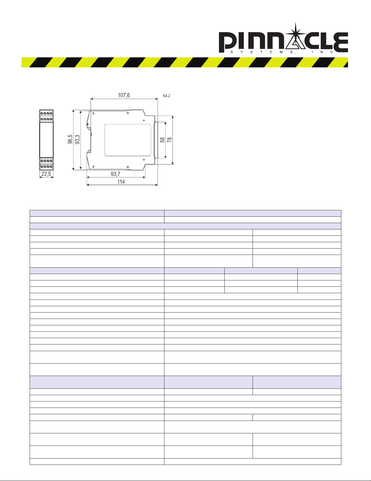
Depth 114 mm
Width 22.5 mm
Height 96.5 mm
(5 + (1,176 x UB / UN - 1) x 100)
≤
Ω
www.pinnaclesystems.com2
Page 3
Instructions
(Translation of the original instructions)
SNO 4083KM
Wieland Electric GmbH
Brennerstraße 10-14
D-96052 Bamberg
Tel. +49 (0) 951 / 9324 -0
Fax +49 (0) 951 / 9324 -198
www.wieland-electric.com
Wieland Electric GmbH
Brennerstraße 10-14
D-96052 Bamberg
Tel. +49 (0) 951 / 9324 -0
Fax +49 (0) 951 / 9324 -198
www.wieland-electric.com
Basic device for EMERGENCY STOP and safety door applications
• Basic device according to EN 60204-1:2007 and EN ISO 13849-1:2007 for single or
two-channel EMERGENCY STOP monitoring.
• PL e / category 4 according to EN ISO 13849-1:2007
• SILCL 3 according to DIN EN 62061:2005
• Stop category 0 according to DIN EN 60204-1
• Manual or automatic start
• With / without crossover detection
• Feedback circuit for monitoring external contactors
• Three enabling current paths, one messaging current path
• Evaluation unit for BWS 4 according to EN 61496-1
• Usage according to EN 81-1 and EN 50156-1
• For connection in series with a pressure sensitive mat according to EN 1760-1
Device versions
R1.188.3580.0—SNO 4083KM-A DC 24 with screw terminals, pluggable
R1.188.3590.0—SNO 4083KM-A AC 115-230 V with screw terminals, pluggable
R1.188.3600.0—SNO 4083KM-C DC 24 V with spring-loaded terminals, pluggable
R1.188.3610.0—SNO 4083KM-C AC 115-230 V with spring-loaded terminals, pluggable
R1.188.3830.0—SNO 4083KM-A 0,5S DC 24 V with screw terminals, pluggable
R1.188.3840.0—SNO 4083KM-A 0,5S AC 115-230 V with screw terminals, pluggable
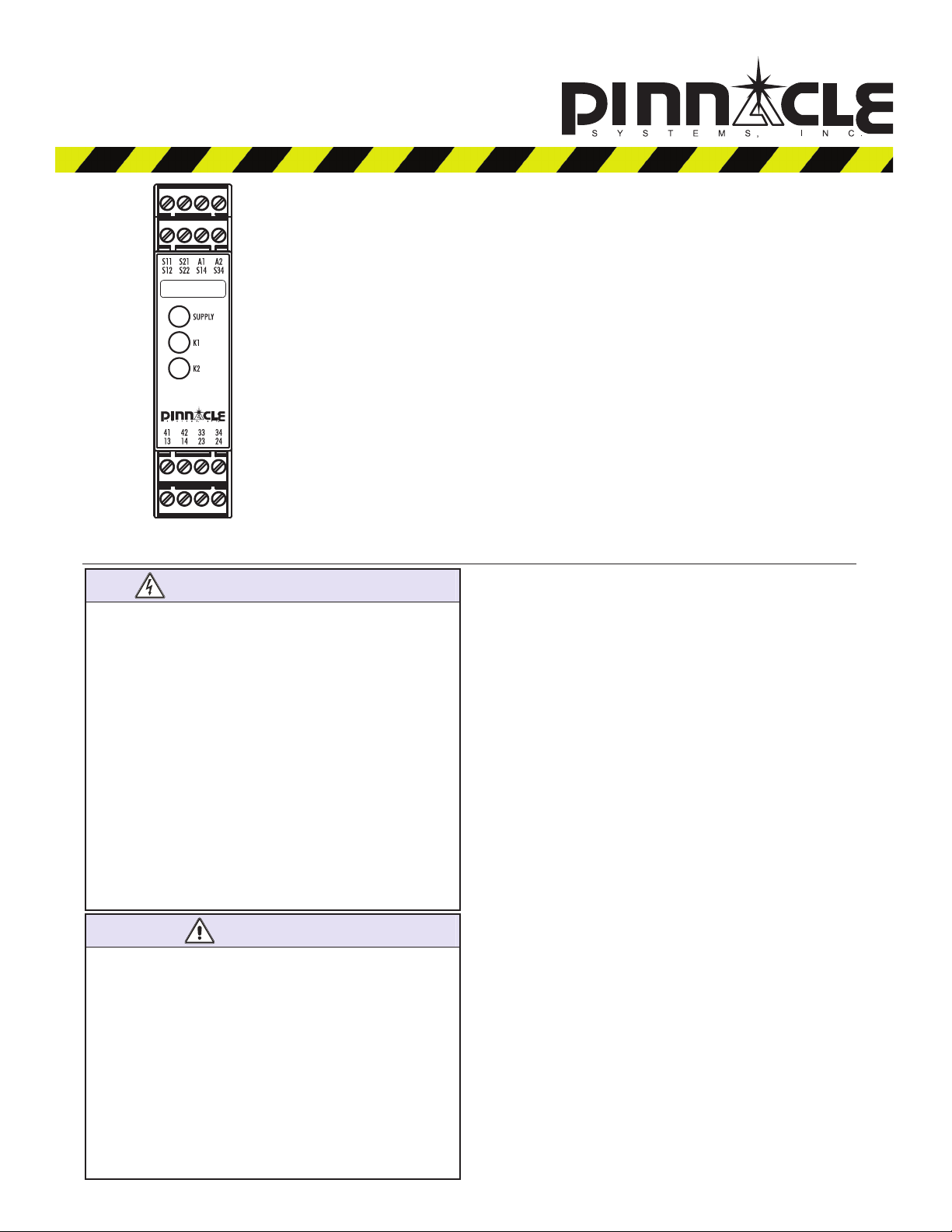
Front view
Basic device for Emergency Stop and Safety Mat applications
Basic device for EMERGENCY STOP and safety door applications
• Basic device according to EN 60204-1:2007 and EN ISO 13849-1:2007 for single or
two-channel EMERGENCY STOP monitoring.
• PL e / category 4 according to EN ISO 13849-1:2007
• SILCL 3 according to DIN EN 62061:2005
• Stop category 0 according to DIN EN 60204-1
• Manual or automatic start
• With / without crossover detection
• Feedback circuit for monitoring external contactors
• Three enabling current paths, one messaging current path
• Evaluation unit for BWS 4 according to EN 61496-1
• Usage according to EN 81-1 and EN 50156-1
• For connection in series with a pressure sensitive mat according to EN 1760-1
Device versions
Front View
R1.188.3580.0—SNO 4083KM-A DC 24 with screw terminals, pluggable
Supply LED green, power supply indicator
R1.188.3590.0—SNO 4083KM-A AC 115-230 V with screw terminals, pluggable
K1, K2 LED green, operation and status indicator for relays K1 and K2
R1.188.3600.0—SNO 4083KM-C DC 24 V with spring-loaded terminals, pluggable
R1.188.3610.0—SNO 4083KM-C AC 115-230 V with spring-loaded terminals, pluggable
R1.188.3830.0—SNO 4083KM-A 0,5S DC 24 V with screw terminals, pluggable
R1.188.3840.0—SNO 4083KM-A 0,5S AC 115-230 V with screw terminals, pluggable
Front view
Supply LED green, power supply indicator
K1, K2 LED green, operation and status indicator for relays K1 and K2
SAFETY REGULATIONS
• Installation, commissioning, modification and retrofitting
must only be performed by a qualified electrician.
• Disconnect the device/the system from the power supply
before starting work. In the case of installation and system
errors, mains voltage can be present on the control circuit in
1 Proper use
The devices are safety switching devices. They must only be
used as components of safety equipment on machines that is
intended for the protection of persons, material, functions and
machinery.
the case of non-galvanically isolated devices.
• Observe the electrotechnical and professional trade associa-
2 Function
tion safety regulations for installation of the equipment.
• Opening the case or other manipulation voids any war-
ranty.
• In the case of improper use or any use other than for the
intended purpose, the device must no longer be used and
any warranty claim is void. Invalidating causes can be:
strong mechanical loading of the device, such as occur
when falling or voltages, currents, temperatures, humidity
outside the specifications.
• Always check all safety functions in accordance with the
applicable regulations during initial commissioning of your
machine/system and observe the specified inspection cycles for safety devices.
ATTENTION
• Take the following safety precautions before starting
installation / assembly or dismantling:
1. Disconnect the device / the system from the power
supply before starting work.
2. Secure the machine / system against being switched on
again.
3. Confirm that no voltage is present.
4. Ground the phases and short to ground briefly.
5. Cover and shield neighbouring live parts.
6. The devices must be installed in a switch cabinet with a
protection class of at least IP54.
• Limited contact protection! Protection class according to
EN 60529:
− Case/terminals: IP40/IP20.
− Finger-proof according to EN 50247.
The device is a two-channel safety switching device for EMERGENCY STOP equipment according to EN 60204-1. It performs
self-monitoring during each ON-OFF cycle and is equipped with
positively driven relays. The device is suitable for connection in
series with short-circuiting pressure sensitive mats, pressure
sensitive bumpers or switching edges with 4-wire technology
(without a monitoring resistor).
Basic function: After applying the supply voltage to the
terminals A1/A2 and closed safety inputs, the enabling current
paths are closed when a valid reset signal is established at S34.
The enabling current paths are opened when the safety inputs
are opened/de-energised.
Operating modes / System functions
• Single-channel or two-channel actuation
• With or without crossover detection
• Manual start (triggering with falling edge)
• Automatic start
• Evaluation of signal transmitters featuring equivalent or non-
equivalent switching
Page 4

• The performance level (PL) and safety category in accor-
NOT E
dance with EN ISO 13849-1 depend on the external wiring,
the application case, the choice of control device and how
this is physically arranged on the machine.
• The user must carry out a risk assessment in accordance
with ISO 14121-1.
• The entire system/machine must undergo validation in
accordance with the applicable standards on the basis of
this.
• The stated performance level will only be achieved if, taking
into account the prevailing device load (see EN ISO 13849-1
Table C.1) and the application case, an average number of
switching cycles per year is not exceeded (see EN ISO
13849-1, C.2.3 and Table K.1). Assuming that the B10d
value is 400,000 for the maximum load, the maximum cycle
number would be 400,000 / 0.1 x 30 = 133,333 switching
cycles per year.
• The safety-related characteristics only apply when the relays
are switched at least once per year.
• Operating the device other than specified can result in
malfunctions or destruction of the device.
• The device must be checked to ensure it is in perfect
working order before commissioning, after replacement of
modules and/or in the case of changes to an installation that
has already undergone acceptance.
• For operation at 115–230 VAC, the operating equipment of
the control circuits must be designed for a rated voltage of
300 V. Basic isolation between supply and control circuits.
• The specified times must always be adhered to when
operating the device; otherwise, the device may become
locked. Locking may be reversed by opening the safety
inputs in the proper manner.
NOT E
• The expansion units of the SNE series or external contactors
with positively-driven contacts can be used for duplicating
the enabling current paths
• The contacts must be fused with maximum 6 A operating
class gG.
• Control outputs S11 and S21 are equipped with overload
protection (for short circuits). Once the cause of the error
has been rectified, the device is ready for operation again
after approx. 3 s.
• The control inputs and outputs are only used for the con-
nection of control devices and not for the connection of
external consumers such as lamps, relays or contactors.
• External loads must be equipped with a suitable protection
circuit for the load (e.g. RC elements, varistors, suppressors,
etc.) in order to reduce electromagnetic interference and
increase the service life of the output switching elements.
• The application-specific standards must be observed when
installing and operating the device.
• The safety functions have not been checked by UL. The
certification process has been carried out in accordance
with the requirements for general applications as stipulated
by UL508.
3 Mounting
Mounting Dismantling
1. Attach the device to the DIN
rail.
2. Snap the device on to the
DIN rail by applying slight
pressure in the direction of
the arrow.
3. Press the device down in
the direction of the arrow.
4. While pressed down,
detach the device from the
latching (in the direction
indicated by the arrow) and
remove it from the DIN rail.
4 Terminal diagram
www.pinnaclesystems.com4
Page 5

A
5 Function diagrams
Equivalent actuation with manual start (installation 1, 2, 3, 4, 5, 8)
A1
S11
S12 (CH1)
S22 (CH2)
S34 (Reset)
13/14
23/24
33/34
41/42
S12 (CH1)
S22 (CH2)
S34 (Reset)
13/14
23/24
33/34
41/42
t
tS tBR tMt
B
A
t
R1
t
W
Non-equivalent actuation with automatic start (installation 6, 7)
1
S11
t
tA
B
t
R1
t
W
t
tBR tMtA
S
t
R2
t
t
S
A
t
R2
Page 6

6 Installation
1 – EMERGENCY STOP button, single-channel 2 – EMERGENCY STOP button, two-channel without
crossover detection
S12
3 – Safety light curtain BWS type 4, two-channel with
crossover detection by BWS1)
BWS type 4
S22 S21
Note: Not for 110-230 VAC
S11 S14
with OSSD
S12
5 – Pressure sensitive mat, two-channel with crossover
detection
S22 S21
S11
S14
Safety mat
S11
S21 S22
S12 S14
S12
4 – EMERGENCY STOP button, two-channel with
crossover detection
S11
6 – Solenoid switch, two-channel, non-equivalent, with
crossover detection
Type SMA
actuated
S22
S12 S21
S11
S21
S21 S12
S11
S22 S14
S14
S22 S14
7 – Reset, automatic, with and without feedback circuit
K11 ... K13
S11
S34
S11
S34
www.pinnaclesystems.com6
8 – Reset, manual, monitored, with and without feedback
circuit
K11 ... K13
S21
S34
S21
S34
Page 7

9 – Power supply 10 – Outputs
]
i
hi
[A]
L+/L1
L+ / L1 M / N
A1
A2
7 Contact load derating
I² – Total current
I² [A²]
80
70
60
50
40
30
13
23
33
41
K1
K2
14
K11 K12
M/N
24
34
K13
42
20
10
30
20 40
-10
-20
10
0
8 Relay service life
ng current
tc
w
50
TA[°C
60
T
A,max
Switching cycles
Page 8
SNO 4083KM-A screw terminal SNO 4083KM-C spring-loaded terminal
9 Dimensions
SNO 4083KM-A screw terminal SNO 4083KM-C spring-loaded terminal
9 Dimensions
10 Technical data
NSD-3580
24 VDC
Function EMERGENCY STOP relay
Function indicator 3 LEDs, green
Power circuit
Rated voltage UN 24 V DC 115–230 VAC
Operating voltage range UB: 0.85–1.1 × UN 20.4 to 26.4 VDC 97 to 253 VAC
Rated power 1.6 W 1.8 W / 4.0 VA
Nominal frequency 50-60 Hz
Electrical isolation between supply and control
circuits
Control circuits S11/S21 S12/S22 S14/S34
Rated output voltage 22.5 V DC
Input current 25 mA 3 mA
Max. peak current 100 mA 5 mA
Response time (manual start tA1, autom. start tA2) 250 ms
Minimum activation time tM (manual start) 125 ms
Recovery time tW 120 ms
Release time tR 20 ms
Synchronous time monitoring tS 0.5 s / 1.5 s
Test pulse length tT 4 ms
Test pulse interval T
Permissible test pulse time tTP < 0.8 ms
Test pulse length tTR, of the incoming test pulse < 16 ms
Delay time tD (time between test pulse and incoming
test pulse)
Max. line resistance per channel 2) 24 VDC (5 + (1.176 × UB / UN – 1) × 100) Ω
115–230 VAC 12 Ω
Output circuits Enabling current paths
Contact Normally open Normally closed
Contact type Positively driven
Contact material Ag alloy, gold plated
Rated switching voltage U 230 VAC
Max. thermal permanent current ITH 6 A 2 A
Max. total current I
65°C 9 A2
Utilisation category AC-15 Ue 230 V, Ie 5 A
DC-13 Ue 24 V, Ie 5 A
Short circuit protection 6 A class gG fuse,
Mechanical service life 107 switching cycles
200 ms
TEST
< 48 ms
2
55°C 25 A2
N
13/14, 23/24, 33/34
fuse integral < 100 A²s
Yes
www.pinnaclesystems.com8
NSD-3590
115 TO 230 VAC
Messaging current paths
41/42
Page 9

Terminals and connection data Screw terminals Spring-loaded terminals
Single-core or finely stranded 1 × 0.14–2.5 mm²
2 × 0.2-1.5 mm²
2 × 0.14-0.75 mm²
Finely stranded with wire-end ferrule according to
DIN 46228
1 × 0.25-2.5 mm²
2 × 0.25-0.5 mm²
2 × 0.25–1.5 mm² (trapezoid
crimping)
AWG conductor size (only use Cu wires) 26–14 24–16
Maximum tightening torque 0.5–0.6 Nm (5–7 lbf-in)
Stripping length Max. 8 mm
General data
Air gap and creepage paths between the circuits EN 60664-1
Protection class according to EN 60529
IP40/IP20
case/terminals
Ambient operating temperature –25 to +65 °C
Storage temperature –25 to +75 °C
Weight 0.2 kg
Standards EN ISO 13849-1, EN 62061, EN 81-1, EN 50156-1
Certifications TÜV, cULus (in progress)
11 Error codes and correction
Flashing
code
2 Crossover, can be rectified during operation
3 Process error, failure to observe the correct sequence for two-channel actuation, can be rectified during opera-
tion by repeating the actuation sequence correctly
4 Synchronous time error, synchronous time exceeded in the case of two-channel actuation, can be rectified
during operation by adhering to the synchronous time
5 Maximum reset actuating time exceeded, can be rectified during operation by repeating the reset with the
correct time
6 Configuration error, can be rectified by ensuring the correct terminal assignment for the required configuration,
the device has to be switched off and on again
7 Permissible input voltage limits undershot/overshot S12 and S22, can be rectified by setting the supply voltage
correctly, the device has to be switched off and on again
8 Device temperature too high, can be rectified by reducing the contact loads or the ambient temperature, the
device has to be switched off and on again
≥ 12 Internal monitoring event, please replace the device and contact after sales service
If an error is still indicated even after the cause has been rectified, inputs S12, S22, S14 and S34 must be kept open during
power-on (e.g. pull out the connector). The error should then be cleared and you can perform a restart with the required installation by means of a power-off and power-on operation.
 Loading...