

Page 1

Avid® NewsCutter® Products
Input and Output Guide
make manage move | media
™
Avid
®
Page 2

Copyright and Disclaimer
Product specifications are subject to change without notice and do not represent a commitment on the part
of Avid Technology, Inc.
The software described in this document is furnished under a license agreement. You can obtain a copy of
that license by visiting Avid's Web site at www.avid.com. The terms of that license are also available in the
product in the same directory as the software. The software may not be reverse assembled and may be
used or copied only in accordance with the terms of the license agreement. It is against the law to copy the
software on any medium except as specifically allowed in the license agreement.
Avid products or portions thereof are protected by one or more of the following United States patents:
4,746,994; 4,970,663; 5,045,940; 5,267,351; 5,309,528; 5,355,450; 5,396,594; 5,440,348; 5,452,378;
5,467,288; 5,513,375; 5,528,310; 5,557,423; 5,568,275; 5,577,190; 5,584,006; 5,640,601; 5,644,364;
5,654,737; 5,715,018; 5,724,605; 5,726,717; 5,729,673; 5,745,637; 5,752,029; 5,754,851; 5,781,188;
5,799,150; 5,812,216; 5,852,435; 5,905,841; 5,929,836; 5,929,942; 5,930,445; 5,930,797; 5,946,445;
5,987,501; 5,999,190; 6,016,152; 6,018,337; 6,023,531; 6,023,703; 6,031,529; 6,058,236; 6,061,758;
6,091,778; 6,105,083; 6,118,444; 6,128,001; 6,134,607; 6,137,919; 6,141,691; 6,157,929; 6,160,548;
6,167,404; 6,198,477; 6,201,531; 6,223,211; 6,249,280; 6,269,195; 6,317,158; 6,317,515; 6,330,369;
6,351,557; 6,353,862; 6,357,047; 6,392,710; 6,404,435; 6,407,775; 6,417,891; 6,426,778; 6,449,019;
6,473,094; 6,477,271; 6,489,969; 6,512,522; 6,532,043; 6,539,163; D396,853; D398,912. Additional U.S.
and foreign patents pending.
No part of this document may be reproduced or transmitted in any form or by any means, electronic or
mechanical, including photocopying and recording, for any purpose without the express written permission
of Avid Technology, Inc.
Copyright © 2003 Avid Technology, Inc. and its licensors. All rights reserved.
The following disclaimer is required by Apple Computer, Inc.
APPLE COMPUTER, INC. MAKES NO WARRANTIES WHATSOEVER, EITHER EXPRESS OR IMPLIED,
REGARDING THIS PRODUCT, INCLUDING WARRANTIES WITH RESPECT TO ITS
MERCHANTABILITY OR ITS FITNESS FOR ANY PARTICULAR PURPOSE. THE EXCLUSION OF
IMPLIED WARRANTIES IS NOT PERMITTED BY SOME STATES. THE ABOVE EXCLUSION MAY NOT
APPLY TO YOU. THIS WARRANTY PROVIDES YOU WITH SPECIFIC LEGAL RIGHTS. THERE MAY BE
OTHER RIGHTS THAT YOU MAY HAVE WHICH VARY FROM STATE TO STATE.
The following disclaimer is required by Sam Leffler and Silicon Graphics, Inc. for the use of
their TIFF library:
Copyright © 1988–1997 Sam Leffler
Copyright © 1991–1997 Silicon Graphics, Inc.
Permission to use, copy, modify, distribute, and sell this software [i.e., the TIFF library] and its
documentation for any purpose is hereby granted without fee, provided that (i) the above copyright notices
and this permission notice appear in all copies of the software and related documentation, and (ii) the
names of Sam Leffler and Silicon Graphics may not be used in any advertising or publicity relating to the
software without the specific, prior written permission of Sam Leffler and Silicon Graphics.
THE SOFTWARE IS PROVIDED “AS-IS” AND WITHOUT WARRANTY OF ANY KIND, EXPRESS,
IMPLIED OR OTHERWISE, INCLUDING WITHOUT LIMITATION, ANY WARRANTY OF
MERCHANTABILITY OR FITNESS FOR A PARTICULAR PURPOSE.
IN NO EVENT SHALL SAM LEFFLER OR SILICON GRAPHICS BE LIABLE FOR ANY SPECIAL,
INCIDENTAL, INDIRECT OR CONSEQUENTIAL DAMAGES OF ANY KIND, OR ANY DAMAGES
WHATSOEVER RESULTING FROM LOSS OF USE, DATA OR PROFITS, WHETHER OR NOT ADVISED
OF THE POSSIBILITY OF DAMAGE, AND ON ANY THEORY OF LIABILITY, ARISING OUT OF OR IN
CONNECTION WITH THE USE OR PERFORMANCE OF THIS SOFTWARE.
The following disclaimer is required by the Independent JPEG Group:
Portions of this software are based on work of the Independent JPEG Group.
The following disclaimer is required by Paradigm Matrix:
Portions of this software licensed from Paradigm Matrix.
Page 3

The following disclaimer is required by Ray Sauers Associates, Inc.:
“Install-It” is licensed from Ray Sauers Associates, Inc. End-User is prohibited from taking any action to
derive a source code equivalent of “Install-It,” including by reverse assembly or reverse compilation, Ray
Sauers Associates, Inc. shall in no event be liable for any damages resulting from reseller’s failure to
perform reseller’s obligation; or any damages arising from use or operation of reseller’s products or the
software; or any other damages, including but not limited to, incidental, direct, indirect, special or
consequential Damages including lost profits, or damages resulting from loss of use or inability to use
reseller’s products or the software for any reason including copyright or patent infringement, or lost data,
even if Ray Sauers Associates has been advised, knew or should have known of the possibility of such
damages.
The following disclaimer is required by Videomedia, Inc.:
“Videomedia, Inc. makes no warranties whatsoever, either express or implied, regarding this product,
including warranties with respect to its merchantability or its fitness for any particular purpose.”
“This software contains V-LAN ver. 3.0 Command Protocols which communicate with V-LAN ver. 3.0
products developed by Videomedia, Inc. and V-LAN ver. 3.0 compatible products developed by third parties
under license from Videomedia, Inc. Use of this software will allow “frame accurate” editing control of
applicable videotape recorder decks, videodisc recorders/players and the like.”
The following disclaimer is required by Altura Software, Inc. for the use of its Mac2Win
software and Sample Source Code:
©1993–1998 Altura Software, Inc.
The following disclaimer is required by Ultimatte Corporation:
Certain real-time compositing capabilities are provided under a license of such technology from Ultimatte
Corporation and are subject to copyright protection.
The following disclaimer is required by 3Prong.com Inc.:
Certain waveform and vector monitoring capabilities are provided under a license from 3Prong.com Inc.
Attn. Government User(s). Restricted Rights Legend
U.S. GOVERNMENT RESTRICTED RIGHTS. This Software and its documentation are “commercial
computer software” or “commercial computer software documentation.” In the event that such Software or
documentation is acquired by or on behalf of a unit or agency of the U.S. Government, all rights with
respect to this Software and documentation are subject to the terms of the License Agreement, pursuant to
FAR §12.212(a) and/or DFARS §227.7202-1(a), as applicable.
Trademarks
888 I/O, AirPlay, AirSPACE, AirSPACE HD, AniMatte, AudioSuite, AudioVision, AutoSync, Avid, AVIDdrive,
AVIDdrive Towers, AvidNet, AvidNetwork, AVIDstripe, Avid Unity, Avid Xpress, AVoption, AVX, CamCutter,
ChromaCurve, ChromaWheel, DAE, D-Fi, D-fx, Digidesign, Digidesign Audio Engine, Digidesign Intelligent
Noise Reduction, DigiDrive, DigiTranslator, DINR, D-Verb, Equinox, ExpertRender, FieldPak,
Film Composer, FilmScribe, FluidMotion, HIIP, HyperSPACE, HyperSPACE HDCAM, IllusionFX,
Image Independence, Intraframe, iS9, iS18, iS23, iS36, Lo-Fi, Magic Mask, make manage move | media,
Marquee, Matador, Maxim, MCXpress, Media Composer, MediaDock, MediaDock Shuttle, Media Fusion,
Media Illusion, MediaLog, Media Reader, Media Recorder, MEDIArray, MediaShare, Meridien, MetaSync,
NaturalMatch, Nearchive, NetReview, NewsCutter, OMF, OMF Interchange, OMM,
Open Media Framework, Open Media Management, ProEncode, Pro Tools, QuietDrive, Recti-Fi,
RetroLoop, rS9, rS18, Sci-Fi, Softimage, Sound Designer II, SPACE, SPACEShift, Symphony, the Avid|DS
logo, Trilligent, UnityRAID, Vari-Fi, Video Slave Driver, VideoSPACE, and Xdeck are either registered
trademarks or trademarks of Avid Technology, Inc. in the United States and/or other countries.
iNEWS, iNEWS ControlAir, and Media Browse are trademarks of iNews, LLC.
Page 4

Aaton is a registered trademark of Aaton S.A. Abekas is a registered trademark of Accom, Inc. Acrobat,
Acrobat Reader, Adobe, After Effects, and Photoshop are either registered trademarks or trademarks of
Adobe Systems, Incorporated in the United States and/or other countries. Alias is a registered trademark
and Alias|Wavefront and Wavefront are trademarks of Alias|Wavefront, a division of Silicon Graphics
Limited. Amiga is a registered trademark of Amiga, Inc. Apple, Bento, FireWire, Macintosh, and QuickDraw
are trademarks of Apple Computer, Inc., registered in the U.S. and other countries. Betacam, Betacam SP,
Hi8, I-LINK, and Sony are trademarks and/or service marks of Sony Corporation. Chyron is a registered
trademark of Chyron Corporation. Cineon, Keykode, and Photo CD are trademarks of Eastman Kodak
Company. cleaner and media cleaner are either registered trademarks or trademarks of Discreet Logic
Inc./Autodesk, Inc. in the USA and/or other countries. DVDit! is a trademark of Sonic Solutions. Express,
V-LAN, and VLXi are registered trademark of Videomedia, Inc. FaderMaster Pro is a trademark of JL
Cooper, a division of Sound Technology. Focusrite is a registered trademark of Focusrite Audio Engineering
Ltd. GIF is a Service Mark property of CompuServe Incorporated. IBM and OS/2 are registered trademarks
of International Business Machines Corporation. IEEE is a registered trademark of the Institute of Electrical
and Electronics Engineers, Inc. Ikegami is a registered trademark and Editcam is a trademark of Ikegami
Tsushinki Co., LTD. Jaz and Zip are registered trademarks of Iomega Corporation. Microsoft, Windows, and
Windows Media, are either registered trademarks or trademarks of Microsoft Corporation in the United
States and/or other countries. Norton AntiVirus is a registered trademark of Symantec Corporation.
Paintbrush is a trademark of Zsoft Corporation. Panasonic is a registered trademark of Matsushita Electric
Industrial Company, Limited. Pixar is a registered trademark of Pixar Animation Studios. QuickTime and the
QuickTime logo are trademarks used under license from Apple Computer, Inc. RealSystem is either a
registered trademark or trademark of Real Networks, Inc. in the United States and/or other countries.
Silicon Graphics is a registered trademark of Silicon Graphics, Inc. Sound Forge is a registered trademark
of Sonic Foundry, Inc. Sun is a registered trademark and Sun Raster is a trademark of Sun Microsystems,
Inc. in the United States or other countries. TARGA is a trademark of Pinnacle Systems, Inc., registered in
the U.S. and other countries. Video Toaster is a trademark of NewTek. X Window System is trademark of X
Consortium, Inc. Yamaha is a registered trademark of Yamaha Corporation of America. All other
trademarks contained herein are the property of their respective owners.
Footage
Arizona Images — KNTV Production — Courtesy of Granite Broadcasting, Inc.,
Editor/Producer Bryan Foote.
Canyonlands — Courtesy of the National Park Service/Department of the Interior.
Tornadoes + Belle Isle footage - Courtesy of KWTV News 9
WCAU Fire Story — Courtesy of NBC-10, Philadelphia, PA.
Women in Sports – Paragliding — Courtesy of Legendary Entertainment, Inc.
GOT FOOTAGE?
Editors — Filmmakers — Special Effects Artists — Game Developers — Animators — Educators —
Broadcasters — Content creators of every genre — Just finished an incredible project and want to
share it with the world?
Send us your reels and we may use your footage in our show reel or demo!*
For a copy of our release and Avid’s mailing address, go to www.avid.com/footage.
*Note: Avid cannot guarantee the use of materials submitted.
Avid NewsCutter Products Input and Output Guide • 0130-05728-01 • May 2003
Page 5

Contents
Using This Guide . . . . . . . . . . . . . . . . . . . . . . . . . . . . . . . . . . . . 17
Who Should Use This Guide . . . . . . . . . . . . . . . . . . . . . . . . . . . . . . . . . 17
About This Guide . . . . . . . . . . . . . . . . . . . . . . . . . . . . . . . . . . . . . . . . . . 17
Symbols and Conventions . . . . . . . . . . . . . . . . . . . . . . . . . . . . . . . . . . . 18
If You Need Help . . . . . . . . . . . . . . . . . . . . . . . . . . . . . . . . . . . . . . . . . . 19
Accessing the Online Library . . . . . . . . . . . . . . . . . . . . . . . . . . . . . . . . . 20
If You Have Documentation Comments . . . . . . . . . . . . . . . . . . . . . . . . . 20
How to Order Documentation . . . . . . . . . . . . . . . . . . . . . . . . . . . . . . . . . 21
Avid Educational Services . . . . . . . . . . . . . . . . . . . . . . . . . . . . . . . . . . . 21
Chapter 1 Planning a Project . . . . . . . . . . . . . . . . . . . . . . . . . . . . . . . . . . . 23
Types of Projects . . . . . . . . . . . . . . . . . . . . . . . . . . . . . . . . . . . . . . . . . . 23
Project Resolutions. . . . . . . . . . . . . . . . . . . . . . . . . . . . . . . . . . . . . . . . . 24
Working with Mixed-Resolution Projects . . . . . . . . . . . . . . . . . . . . . . . . 27
NTSC and PAL Image Sizes . . . . . . . . . . . . . . . . . . . . . . . . . . . . . . . . . 27
Software-Only Avid Editing Systems . . . . . . . . . . . . . . . . . . . . . . . . . . . 28
Sample Workflow . . . . . . . . . . . . . . . . . . . . . . . . . . . . . . . . . . . . . . . . . . 29
Video and Film Projects . . . . . . . . . . . . . . . . . . . . . . . . . . . . . . . . . . . . . 30
Chapter 2 Logging. . . . . . . . . . . . . . . . . . . . . . . . . . . . . . . . . . . . . . . . . . . . 31
Logging Tips. . . . . . . . . . . . . . . . . . . . . . . . . . . . . . . . . . . . . . . . . . . . . . 32
Logging Preroll. . . . . . . . . . . . . . . . . . . . . . . . . . . . . . . . . . . . . . . . . 32
Logging Timecode . . . . . . . . . . . . . . . . . . . . . . . . . . . . . . . . . . . . . . 33
Naming Tapes . . . . . . . . . . . . . . . . . . . . . . . . . . . . . . . . . . . . . . . . . 35
Double-Checking the Logs. . . . . . . . . . . . . . . . . . . . . . . . . . . . . . . . 35
Adding a Memory Mark . . . . . . . . . . . . . . . . . . . . . . . . . . . . . . . . . . 36
Page 6

Preparing Logs for Import . . . . . . . . . . . . . . . . . . . . . . . . . . . . . . . . . . . . 37
Creating Avid Logs . . . . . . . . . . . . . . . . . . . . . . . . . . . . . . . . . . . . . . 37
Importing Shot Log Files. . . . . . . . . . . . . . . . . . . . . . . . . . . . . . . . . . 38
Setting the Pulldown Phase . . . . . . . . . . . . . . . . . . . . . . . . . . . . . . . . . . 41
Converting Log Files with Avid Log Exchange . . . . . . . . . . . . . . . . . . . . 43
Converting a Log File to an ALE File . . . . . . . . . . . . . . . . . . . . . . . . 44
Using Drag-and-Drop Conversion . . . . . . . . . . . . . . . . . . . . . . . . . . 48
Logging Directly to a Bin . . . . . . . . . . . . . . . . . . . . . . . . . . . . . . . . . . . . . 50
Logging with an Avid-Controlled Camera or Deck . . . . . . . . . . . . . . 50
Pausing a Deck While Logging. . . . . . . . . . . . . . . . . . . . . . . . . . . . . 54
Logging with a Non-Avid-Controlled Camera or Deck . . . . . . . . . . . 56
Logging Film Information. . . . . . . . . . . . . . . . . . . . . . . . . . . . . . . . . . . . . 58
Displaying Film Columns . . . . . . . . . . . . . . . . . . . . . . . . . . . . . . . . . 59
Entering Pulldown Information . . . . . . . . . . . . . . . . . . . . . . . . . . . . . 60
Determining the Pulldown Phase . . . . . . . . . . . . . . . . . . . . . . . . 62
Modifying the Pulldown Phase Before Capturing. . . . . . . . . . . . 63
Entering Frames-per-Second Rates for PAL Transfers . . . . . . . . . . 65
Entering Key Numbers . . . . . . . . . . . . . . . . . . . . . . . . . . . . . . . . . . . 65
Entering Additional Timecodes (Option) . . . . . . . . . . . . . . . . . . . . . . 66
Entering the Ink Number (Option). . . . . . . . . . . . . . . . . . . . . . . . . . . 67
Entering Additional Film Data . . . . . . . . . . . . . . . . . . . . . . . . . . . . . . 67
Modifying Clip Information Before Capturing . . . . . . . . . . . . . . . . . . . . . 68
The Modify Command . . . . . . . . . . . . . . . . . . . . . . . . . . . . . . . . . . . 68
Using the Modify Command . . . . . . . . . . . . . . . . . . . . . . . . . . . . . . . 69
Options for Modifying Bin Information. . . . . . . . . . . . . . . . . . . . . . . . 70
Modifying in the Bin . . . . . . . . . . . . . . . . . . . . . . . . . . . . . . . . . . . . . 71
Exporting Shot Log Files . . . . . . . . . . . . . . . . . . . . . . . . . . . . . . . . . . . . . 72
Chapter 3 Preparing to Capture . . . . . . . . . . . . . . . . . . . . . . . . . . . . . . . . . 75
Understanding Digital Video (DV) . . . . . . . . . . . . . . . . . . . . . . . . . . . . . . 76
Preparing the Hardware . . . . . . . . . . . . . . . . . . . . . . . . . . . . . . . . . . . . . 77
Selecting Settings . . . . . . . . . . . . . . . . . . . . . . . . . . . . . . . . . . . . . . . . . . 77
Using General Settings. . . . . . . . . . . . . . . . . . . . . . . . . . . . . . . . . . . 77
Transfer Settings for Film Projects . . . . . . . . . . . . . . . . . . . . . . . . . . 78
Selecting Capture Settings . . . . . . . . . . . . . . . . . . . . . . . . . . . . . . . . 80
6
Page 7

Creating a GPI Trigger. . . . . . . . . . . . . . . . . . . . . . . . . . . . . . . . . . . 81
Deleting a GPI Setting . . . . . . . . . . . . . . . . . . . . . . . . . . . . . . . . . . . 83
Editing an Existing GPI Setting . . . . . . . . . . . . . . . . . . . . . . . . . . . . 84
Configuring Decks . . . . . . . . . . . . . . . . . . . . . . . . . . . . . . . . . . . . . . . . . 84
Deck Settings Options . . . . . . . . . . . . . . . . . . . . . . . . . . . . . . . . . . . 89
Deleting Deck Configurations . . . . . . . . . . . . . . . . . . . . . . . . . . . . . 92
Setting Deck Preferences . . . . . . . . . . . . . . . . . . . . . . . . . . . . . . . . 92
Understanding Drop-Frame and Non-Drop-Frame Timecodes . . . . . . . 93
Setting Up the Capture Tool . . . . . . . . . . . . . . . . . . . . . . . . . . . . . . . . . . 94
Opening the Capture Tool . . . . . . . . . . . . . . . . . . . . . . . . . . . . . . . . 95
Setting the Video and Audio Input . . . . . . . . . . . . . . . . . . . . . . . . . . 95
Selecting Video Input. . . . . . . . . . . . . . . . . . . . . . . . . . . . . . . . . 96
Selecting Audio Input. . . . . . . . . . . . . . . . . . . . . . . . . . . . . . . . . 96
Selecting a Deck . . . . . . . . . . . . . . . . . . . . . . . . . . . . . . . . . . . . . . . 97
Selecting a Tape . . . . . . . . . . . . . . . . . . . . . . . . . . . . . . . . . . . . . . . 98
Selecting Source Tracks . . . . . . . . . . . . . . . . . . . . . . . . . . . . . . . . . 99
Setting the Video and Audio Input . . . . . . . . . . . . . . . . . . . . . . . . . 100
Setting the Pulldown Switch . . . . . . . . . . . . . . . . . . . . . . . . . . 101
Film Project Pulldown and Transfer Settings. . . . . . . . . . . . . . 102
Selecting a Resolution in the Capture Tool . . . . . . . . . . . . . . . . . . 103
Selecting a Format in the Capture Tool . . . . . . . . . . . . . . . . . . . . . 104
Selecting a Draft Resolution for DV Media . . . . . . . . . . . . . . . . . . 104
Selecting a Target Bin . . . . . . . . . . . . . . . . . . . . . . . . . . . . . . . . . . 104
Selecting the Target Drives . . . . . . . . . . . . . . . . . . . . . . . . . . . . . . 105
Targeting a Single Drive . . . . . . . . . . . . . . . . . . . . . . . . . . . . . 105
Targeting Separate Drives for Audio and Video . . . . . . . . . . . 106
Interpreting the Time Remaining Display. . . . . . . . . . . . . . . . . . . . 107
Capturing to Multiple Media Files. . . . . . . . . . . . . . . . . . . . . . . . . . 108
Selecting the Preroll Method . . . . . . . . . . . . . . . . . . . . . . . . . . . . . 111
Capturing Across Timecode Breaks . . . . . . . . . . . . . . . . . . . . . . . 112
Preparing for Audio Input . . . . . . . . . . . . . . . . . . . . . . . . . . . . . . . . . . . 113
Selecting the Audio File Format. . . . . . . . . . . . . . . . . . . . . . . . . . . 113
Establishing Sync for Audio-Only Input . . . . . . . . . . . . . . . . . . . . . 115
Checking for a Valid Digital Sync Signal . . . . . . . . . . . . . . . . . . . . 115
Adjusting Audio Project Settings . . . . . . . . . . . . . . . . . . . . . . . . . . 116
7
Page 8

Configuring the Sound Card . . . . . . . . . . . . . . . . . . . . . . . . . . . . . . 117
Using the Audio Tool . . . . . . . . . . . . . . . . . . . . . . . . . . . . . . . . . . . 119
Resizing the Audio Tool . . . . . . . . . . . . . . . . . . . . . . . . . . . . . . 120
Adjusting the Reference Level . . . . . . . . . . . . . . . . . . . . . . . . . 121
Selecting a Peak Hold Option . . . . . . . . . . . . . . . . . . . . . . . . . 121
Adjusting Audio Input Levels . . . . . . . . . . . . . . . . . . . . . . . . . . 122
Creating Tone Media . . . . . . . . . . . . . . . . . . . . . . . . . . . . . . . . 124
Calibrating Input Channels for the Audio I/O Device . . . . . . . . 126
Calibrating Output Channels for the Audio I/O Device. . . . . . . 127
Using the Passthrough Mix Tool. . . . . . . . . . . . . . . . . . . . . . . . . . . 128
Resizing the Passthrough Mix Tool . . . . . . . . . . . . . . . . . . . . . 129
Monitoring Audio with the Passthrough Mix Tool. . . . . . . . . . . 129
Changing an Audio Level in the Passthrough Mix Tool . . . . . . 130
Adjusting Pan Values in the Passthrough Mix Tool . . . . . . . . . 131
Audio Meters in the Timeline. . . . . . . . . . . . . . . . . . . . . . . . . . . . . . . . . 131
Using the Meter Menu . . . . . . . . . . . . . . . . . . . . . . . . . . . . . . . . . . 132
Adjusting Volume Control . . . . . . . . . . . . . . . . . . . . . . . . . . . . . . . . 133
Using the Console Window to Check Audio Levels . . . . . . . . . . . . 135
Calibrating for Video Input. . . . . . . . . . . . . . . . . . . . . . . . . . . . . . . . . . . 136
Manually Calibrating for Video Input. . . . . . . . . . . . . . . . . . . . . . . . 137
Limitation When Using Consumer Decks or Decks Without
Time-Base Correctors . . . . . . . . . . . . . . . . . . . . . . . . . . . . . . . . . 142
Capturing from Unstable Time-Base Sources . . . . . . . . . . . . . 142
Green Line in VHS Video . . . . . . . . . . . . . . . . . . . . . . . . . . . . . 143
Saving Video Input Settings . . . . . . . . . . . . . . . . . . . . . . . . . . . . . . 143
Saving a Custom Default Setting for the Video Input Tool . . . . . . . 145
Adjusting Video Levels Without Color Bars . . . . . . . . . . . . . . . . . . 146
Compression Resolutions and Storage Requirements . . . . . . . . . . . . . 146
Screen Resolution . . . . . . . . . . . . . . . . . . . . . . . . . . . . . . . . . . . . . 147
Digital Video Resolutions . . . . . . . . . . . . . . . . . . . . . . . . . . . . . . . . 148
JFIF Compression and Resolutions . . . . . . . . . . . . . . . . . . . . . . . . 148
Compression Groups and Image Quality. . . . . . . . . . . . . . . . . 149
Video Streams . . . . . . . . . . . . . . . . . . . . . . . . . . . . . . . . . . . . . 149
8
Page 9

Compression Specifications . . . . . . . . . . . . . . . . . . . . . . . . . . 149
Mixing Resolutions . . . . . . . . . . . . . . . . . . . . . . . . . . . . . . . . . 151
Setting Media Creation Resolutions and Selecting Drives. . . . . . . 152
Chapter 4 Capturing Media. . . . . . . . . . . . . . . . . . . . . . . . . . . . . . . . . . . . 155
Before You Begin Capturing. . . . . . . . . . . . . . . . . . . . . . . . . . . . . . . . . 156
Adding Clip Names and Comments On-the-Fly . . . . . . . . . . . . . . . . . . 157
Adding Extra Text Fields in the Capture Tool. . . . . . . . . . . . . . . . . . . . 157
Adding Locators On-the-Fly . . . . . . . . . . . . . . . . . . . . . . . . . . . . . . 160
Creating Subclips On-the-Fly . . . . . . . . . . . . . . . . . . . . . . . . . . . . . 160
DV Capture Offset . . . . . . . . . . . . . . . . . . . . . . . . . . . . . . . . . . . . . . . . 161
Capturing and Logging at the Same Time . . . . . . . . . . . . . . . . . . . . . . 163
Capturing from One Point to Another. . . . . . . . . . . . . . . . . . . . . . . 164
Capturing from an IN Point to an OUT Point . . . . . . . . . . . . . . 164
Setting Both Marks . . . . . . . . . . . . . . . . . . . . . . . . . . . . . . . . . 165
Setting Only One Mark . . . . . . . . . . . . . . . . . . . . . . . . . . . . . . 166
Capturing On-the-Fly . . . . . . . . . . . . . . . . . . . . . . . . . . . . . . . . . . . 167
Autocapture . . . . . . . . . . . . . . . . . . . . . . . . . . . . . . . . . . . . . . . . . . 169
Capturing with Time-of-Day Timecode . . . . . . . . . . . . . . . . . . . . . 172
Capturing in Satellite Mode or No Device Control . . . . . . . . . . . . . 172
Setting a Timed Capture . . . . . . . . . . . . . . . . . . . . . . . . . . . . . . . . 176
Capturing Audio from a Music CD . . . . . . . . . . . . . . . . . . . . . . . . . . . . 179
Capturing to the Timeline . . . . . . . . . . . . . . . . . . . . . . . . . . . . . . . . . . . 181
Patching When Capturing to the Timeline . . . . . . . . . . . . . . . . . . . 182
Batch Capturing from Logged Clips . . . . . . . . . . . . . . . . . . . . . . . . . . . 183
Preparing to Batch Capture . . . . . . . . . . . . . . . . . . . . . . . . . . . . . . 183
Batch Capturing Clips . . . . . . . . . . . . . . . . . . . . . . . . . . . . . . . . . . 184
Modifying the Pulldown Phase After Capturing . . . . . . . . . . . . . . . . . . 187
DV Scene Extraction . . . . . . . . . . . . . . . . . . . . . . . . . . . . . . . . . . . . . . 189
Setting Up DV Scene Extraction Before Capturing . . . . . . . . . . . . 190
Setting Up DV Scene Extraction After Capturing. . . . . . . . . . . . . . 192
Recapturing Your Material . . . . . . . . . . . . . . . . . . . . . . . . . . . . . . . . . . 193
Recapturing Master Clips and Subclips. . . . . . . . . . . . . . . . . . . . . 193
9
Page 10

Recapturing Sequences . . . . . . . . . . . . . . . . . . . . . . . . . . . . . . . . . 194
Saving Two Versions of a Sequence When Recapturing . . . . 194
Recapturing the Sequence. . . . . . . . . . . . . . . . . . . . . . . . . . . . 194
Other Capture Functions. . . . . . . . . . . . . . . . . . . . . . . . . . . . . . . . . . . . 196
Working in Quick Record Mode . . . . . . . . . . . . . . . . . . . . . . . . . . . 196
Controlling Decks from the Keyboard. . . . . . . . . . . . . . . . . . . . . . . 198
Naming a New Tape from the Keyboard . . . . . . . . . . . . . . . . . . . . 199
Ejecting Tapes with a Button or Key. . . . . . . . . . . . . . . . . . . . . . . . 199
Returning to the Previous Place in the Select Tape Dialog Box. . . 200
Chapter 5 Importing Files. . . . . . . . . . . . . . . . . . . . . . . . . . . . . . . . . . . . . 201
Preparing to Import Files. . . . . . . . . . . . . . . . . . . . . . . . . . . . . . . . . . . . 201
Working with Mixed-Resolution Projects. . . . . . . . . . . . . . . . . . . . . . . . 202
Creating and Using Import Settings . . . . . . . . . . . . . . . . . . . . . . . . . . . 202
Importing Files. . . . . . . . . . . . . . . . . . . . . . . . . . . . . . . . . . . . . . . . . . . . 205
Using the Drag-and-Drop Method to Import Files . . . . . . . . . . . . . . . . . 209
Importing Photoshop Graphics . . . . . . . . . . . . . . . . . . . . . . . . . . . . . . . 210
Importing Single-Layer Photoshop Graphics . . . . . . . . . . . . . . . . . 210
Importing Multilayered Photoshop Graphics. . . . . . . . . . . . . . . . . . 211
Understanding Multilayered Graphics Import. . . . . . . . . . . . . . 211
Importing Multilayered Files . . . . . . . . . . . . . . . . . . . . . . . . . . . 215
Importing Editcam Files. . . . . . . . . . . . . . . . . . . . . . . . . . . . . . . . . . . . . 217
Reimporting Files . . . . . . . . . . . . . . . . . . . . . . . . . . . . . . . . . . . . . . . . . 219
The Batch Import Dialog Box . . . . . . . . . . . . . . . . . . . . . . . . . . . . . 219
Selected Clips Section . . . . . . . . . . . . . . . . . . . . . . . . . . . . . . . 220
Import Target Section. . . . . . . . . . . . . . . . . . . . . . . . . . . . . . . . 221
Import Options Section. . . . . . . . . . . . . . . . . . . . . . . . . . . . . . . 221
Starting the Reimport Process . . . . . . . . . . . . . . . . . . . . . . . . . . . . 221
10
Chapter 6 Output Options. . . . . . . . . . . . . . . . . . . . . . . . . . . . . . . . . . . . . 225
Preparing for Output . . . . . . . . . . . . . . . . . . . . . . . . . . . . . . . . . . . . . . . 226
Selecting Video Output . . . . . . . . . . . . . . . . . . . . . . . . . . . . . . . . . . 226
Establishing Sync for Output . . . . . . . . . . . . . . . . . . . . . . . . . . . . . 227
Calibrating for Video Output . . . . . . . . . . . . . . . . . . . . . . . . . . . . . . 227
Using the Factory Preset Buttons . . . . . . . . . . . . . . . . . . . . . . 228
Page 11

Basic Video Output Calibration . . . . . . . . . . . . . . . . . . . . . . . . 228
Using Test Patterns . . . . . . . . . . . . . . . . . . . . . . . . . . . . . . . . . 233
Adjusting Phase Controls . . . . . . . . . . . . . . . . . . . . . . . . . . . . 234
Calibrating the System with Passthrough Signals. . . . . . . . . . 234
Calibrating for Audio Output. . . . . . . . . . . . . . . . . . . . . . . . . . . . . . 236
Setting the Calibration Tone . . . . . . . . . . . . . . . . . . . . . . . . . . 236
Calibrating Global Output Levels. . . . . . . . . . . . . . . . . . . . . . . 237
Adjusting Audio Output . . . . . . . . . . . . . . . . . . . . . . . . . . . . . . 237
Preparing Record Tapes . . . . . . . . . . . . . . . . . . . . . . . . . . . . . . . . 240
Frame-Accurate Capture . . . . . . . . . . . . . . . . . . . . . . . . . . . . . 240
Manual Recording . . . . . . . . . . . . . . . . . . . . . . . . . . . . . . . . . . 241
Recording Bars and Tone . . . . . . . . . . . . . . . . . . . . . . . . . . . . 241
Enabling Assemble-Edit Recording . . . . . . . . . . . . . . . . . . . . . . . . 242
Using the Digital Cut Tool. . . . . . . . . . . . . . . . . . . . . . . . . . . . . . . . . . . 244
Selecting a Deck in the Digital Cut Tool. . . . . . . . . . . . . . . . . . . . . 246
Previewing a Digital Cut. . . . . . . . . . . . . . . . . . . . . . . . . . . . . . . . . 247
Outputting Directly to a DV Device . . . . . . . . . . . . . . . . . . . . . . . . 249
Performing a Digital Cut to Tape (Remote Mode) . . . . . . . . . . . . . 250
Performing a Digital Cut to Tape (Local Mode) . . . . . . . . . . . . . . . 254
DV Digital Cut Delay. . . . . . . . . . . . . . . . . . . . . . . . . . . . . . . . . . . . . . . 257
Understanding Passthrough . . . . . . . . . . . . . . . . . . . . . . . . . . . . . . . . . 258
Using EDL Manager . . . . . . . . . . . . . . . . . . . . . . . . . . . . . . . . . . . . . . . 258
Chapter 7 Exporting and Exchanging Material. . . . . . . . . . . . . . . . . . . . 259
Exporting Files . . . . . . . . . . . . . . . . . . . . . . . . . . . . . . . . . . . . . . . . . . . 260
Preparing to Export a Sequence . . . . . . . . . . . . . . . . . . . . . . . . . . . . . 261
Mixing Down Video Tracks . . . . . . . . . . . . . . . . . . . . . . . . . . . . . . . . . . 262
Exporting Frames, Clips, or Sequences. . . . . . . . . . . . . . . . . . . . . . . . 264
Using the Drag-and-Drop Method for Export . . . . . . . . . . . . . . . . . 266
Using ProEncode . . . . . . . . . . . . . . . . . . . . . . . . . . . . . . . . . . . . . . . . . 268
Using AvidLinks . . . . . . . . . . . . . . . . . . . . . . . . . . . . . . . . . . . . . . . . . . 269
Creating Files for a DVD. . . . . . . . . . . . . . . . . . . . . . . . . . . . . . . . . . . . 271
Exporting Video in DV Stream Format . . . . . . . . . . . . . . . . . . . . . . . . . 274
11
Page 12

Customizing Export Settings . . . . . . . . . . . . . . . . . . . . . . . . . . . . . . . . . 276
Preset Export Templates . . . . . . . . . . . . . . . . . . . . . . . . . . . . . . . . 276
Creating a New Export Setting . . . . . . . . . . . . . . . . . . . . . . . . . . . . 277
Exporting OMFI and AAF Files . . . . . . . . . . . . . . . . . . . . . . . . . . . . . . . 278
Exporting Through OMF Interchange. . . . . . . . . . . . . . . . . . . . . . . 279
Exporting Through AAF . . . . . . . . . . . . . . . . . . . . . . . . . . . . . . . . . 280
Selecting an OMFI or an AAF Transfer Method . . . . . . . . . . . . . . . 280
Exporting OMFI or AAF Files . . . . . . . . . . . . . . . . . . . . . . . . . . . . . 281
Exchanging Titles in OMFI Format . . . . . . . . . . . . . . . . . . . . . . . . . . . . 283
QuickTime Reference Movies . . . . . . . . . . . . . . . . . . . . . . . . . . . . . . . . 284
Exporting as a QuickTime Reference Movie . . . . . . . . . . . . . . . . . 284
Exporting as a QuickTime Movie . . . . . . . . . . . . . . . . . . . . . . . . . . 286
Selecting QuickTime Codecs . . . . . . . . . . . . . . . . . . . . . . . . . . . . . 289
Exporting As an AVI File . . . . . . . . . . . . . . . . . . . . . . . . . . . . . . . . . . . . 291
Avid Codecs . . . . . . . . . . . . . . . . . . . . . . . . . . . . . . . . . . . . . . . . . . . . . 296
Using the Avid Codecs for QuickTime . . . . . . . . . . . . . . . . . . . . . . 296
Exporting with the Avid DV Codec or an
Avid Meridien Codec. . . . . . . . . . . . . . . . . . . . . . . . . . . . . . . 297
Exporting with the Avid ABVB NuVista Codec
for QuickTime . . . . . . . . . . . . . . . . . . . . . . . . . . . . . . . . . . . . 300
Installing an Avid Codec on Other Systems . . . . . . . . . . . . . . . . . . 303
Copying an Avid Codec for QuickTime to a
Windows System . . . . . . . . . . . . . . . . . . . . . . . . . . . . . . . . . 303
Downloading Avid Codecs for QuickTime . . . . . . . . . . . . . . . . 304
Exporting from a Third-Party Application . . . . . . . . . . . . . . . . . . . . 305
Exporting Tracks As Audio Files . . . . . . . . . . . . . . . . . . . . . . . . . . . . . . 305
Exporting As a Graphics File. . . . . . . . . . . . . . . . . . . . . . . . . . . . . . . . . 307
Transferring a Project Between Systems . . . . . . . . . . . . . . . . . . . . . . . 309
Methods for Transferring Files Between Avid Editing Systems . . . 309
Compatibility Requirements for Transfer . . . . . . . . . . . . . . . . . . . . 310
Transferring a Project and Associated Media Files . . . . . . . . . . . . 310
Transferring Projects, User Profiles, and Site Settings. . . . . . . . . . 312
Transferring Projects and Bins Using AFE Files. . . . . . . . . . . . . . . 313
Transferring Media to and from a Video Server . . . . . . . . . . . . . . . . . . 315
Setting Up a Video Server . . . . . . . . . . . . . . . . . . . . . . . . . . . . . . . 316
12
Page 13

Configuring the Video Server . . . . . . . . . . . . . . . . . . . . . . . . . 316
Configuring the Video Server As a Deck. . . . . . . . . . . . . . . . . 316
Transferring from the Avid Editing System to the Video Server. . . 317
Transferring from the Video Server to the Avid Editing System. . . 319
Chapter 8 Using the NRCS Tool. . . . . . . . . . . . . . . . . . . . . . . . . . . . . . . . 321
Configuring the NRCS Tool . . . . . . . . . . . . . . . . . . . . . . . . . . . . . . . . . 322
Configuring the ENPS Server for Avid Clients. . . . . . . . . . . . . . . . 322
Configuring the NRCS Settings . . . . . . . . . . . . . . . . . . . . . . . . . . . 325
Starting the NRCS Tool . . . . . . . . . . . . . . . . . . . . . . . . . . . . . . . . . . . . 328
Understanding the NRCS Tool . . . . . . . . . . . . . . . . . . . . . . . . . . . . . . . 329
Using the Directory Panel. . . . . . . . . . . . . . . . . . . . . . . . . . . . . . . . . . . 332
Opening a Story . . . . . . . . . . . . . . . . . . . . . . . . . . . . . . . . . . . . . . . 333
Creating a Shortcut to a Directory (iNEWS Only) . . . . . . . . . . . . . 334
Removing a Shortcut to a Directory (iNEWS Only) . . . . . . . . . . . . 334
Deleting a Story (iNEWS Only) . . . . . . . . . . . . . . . . . . . . . . . . . . . 334
Changing the Text Display . . . . . . . . . . . . . . . . . . . . . . . . . . . . . . . . . . 335
Editing Story Text (iNEWS Only) . . . . . . . . . . . . . . . . . . . . . . . . . . . . . 335
Rearranging Text in a Story (iNEWS Only) . . . . . . . . . . . . . . . . . . 336
Marking Text As Presenter Instructions (iNEWS Only) . . . . . . . . . 336
Marking Text As Closed Caption (iNEWS Only) . . . . . . . . . . . . . . 337
Adding a Production Cue (iNEWS Only) . . . . . . . . . . . . . . . . . . . . 338
Deleting a Production Cue (iNEWS Only) . . . . . . . . . . . . . . . . . . . 339
Marking Text As Machine Control (iNEWS Only) . . . . . . . . . . . . . 339
Formatting Text (iNEWS Only) . . . . . . . . . . . . . . . . . . . . . . . . . . . 339
Marking Text As Normal (iNEWS Only) . . . . . . . . . . . . . . . . . . . . . 340
Adding a Loaded Cue (iNEWS Only) . . . . . . . . . . . . . . . . . . . . . . . 340
Using a Loaded Cue (iNEWS Only). . . . . . . . . . . . . . . . . . . . . . . . 341
Deleting a Loaded Cue (iNEWS Only). . . . . . . . . . . . . . . . . . . . . . 342
Finding the Read Time of a Story. . . . . . . . . . . . . . . . . . . . . . . . . . . . . 342
Building a Sequence from a Story . . . . . . . . . . . . . . . . . . . . . . . . . . . . 344
Script-Based IN and OUT Points . . . . . . . . . . . . . . . . . . . . . . . . . . 347
Setting Timeline IN and OUT Points Based on Story Timing. . . . . 347
13
Page 14

Adjusting the Story Timing (iNEWS Only). . . . . . . . . . . . . . . . . . . . . . . 349
Adjusting the Story Timing with a Time Marker (iNEWS Only). . . . 350
Adjusting the Story Timing with a Time Pad (iNEWS Only) . . . . . . 350
Using Associated Sequences . . . . . . . . . . . . . . . . . . . . . . . . . . . . . . . . 352
Saving Changes to a Story (iNEWS Only) . . . . . . . . . . . . . . . . . . . . . . 354
Using the Post to Web Feature . . . . . . . . . . . . . . . . . . . . . . . . . . . . . . . 355
Processing the Script . . . . . . . . . . . . . . . . . . . . . . . . . . . . . . . . . . . 355
Creating a Web Page . . . . . . . . . . . . . . . . . . . . . . . . . . . . . . . . . . . 355
Linking Clips . . . . . . . . . . . . . . . . . . . . . . . . . . . . . . . . . . . . . . . . . . 357
Using Templates. . . . . . . . . . . . . . . . . . . . . . . . . . . . . . . . . . . . . . . 360
The Story Tag . . . . . . . . . . . . . . . . . . . . . . . . . . . . . . . . . . . . . 361
The Text Tag . . . . . . . . . . . . . . . . . . . . . . . . . . . . . . . . . . . . . . 361
The Clip Tag. . . . . . . . . . . . . . . . . . . . . . . . . . . . . . . . . . . . . . . 363
Using a Template with Post to Web . . . . . . . . . . . . . . . . . . . . . . . . 365
Posting a Story to the Web . . . . . . . . . . . . . . . . . . . . . . . . . . . . . . . 367
Sending and Receiving NRCS Mail (iNEWS Only). . . . . . . . . . . . . . . . 370
Sending NRCS Tool Mail (iNEWS only). . . . . . . . . . . . . . . . . . . . . 370
Receiving NRCS Tool Mail (iNEWS only). . . . . . . . . . . . . . . . . . . . 371
Disconnecting from Your NRCS Server . . . . . . . . . . . . . . . . . . . . . . . . 372
14
Index . . . . . . . . . . . . . . . . . . . . . . . . . . . . . . . . . . . . . . . . . . . . . 373
Page 15

Tables
Table 1 Supported Resolutions and Field Dimensions. . . . . . . . . .26
Table 2 Line Endings Options. . . . . . . . . . . . . . . . . . . . . . . . . . . . .45
Table 3 Options for Modifying Bin Information . . . . . . . . . . . . . . . .70
Table 4 GPI Settings Options . . . . . . . . . . . . . . . . . . . . . . . . . . . . .82
Table 5 GPI Node Settings Options . . . . . . . . . . . . . . . . . . . . . . . .83
Table 6 Deck Settings Options . . . . . . . . . . . . . . . . . . . . . . . . . . . .90
Table 7 Film Project Pulldown and Transfer Settings. . . . . . . . . .102
Table 8 Audio Tool Components . . . . . . . . . . . . . . . . . . . . . . . . .120
Table 9 Audio Meter Menu Options . . . . . . . . . . . . . . . . . . . . . . .132
Table 10 Luminance Settings for Video Input. . . . . . . . . . . . . . . . .139
Table 11 Video Level Adjustment Criteria . . . . . . . . . . . . . . . . . . .146
Table 12 Compression Resolution Specifications . . . . . . . . . . . . .150
Table 13 Scheduled Record Settings . . . . . . . . . . . . . . . . . . . . . . .176
Table 14 Quick Record Condition Messages . . . . . . . . . . . . . . . . .196
Table 15 Support for Photoshop Layer Options . . . . . . . . . . . . . . .214
Table 16 Support for Photoshop Special Layer Types . . . . . . . . . .215
Table 17 Video Format Output Parameters . . . . . . . . . . . . . . . . . .230
Table 18 Luminance Settings for Video Output . . . . . . . . . . . . . . .232
Table 19 Available Avid Applications for AvidLinks Export. . . . . . .270
Table 20 DVD Options . . . . . . . . . . . . . . . . . . . . . . . . . . . . . . . . . .273
Table 21 Devices for Transferring Files . . . . . . . . . . . . . . . . . . . . .310
Table 22 Default Folder and File Locations . . . . . . . . . . . . . . . . . .312
Table 23 NRCS Tool Components . . . . . . . . . . . . . . . . . . . . . . . . .331
15
Page 16

16
Page 17

Using This Guide
The Avid® NewsCutter® products help editors, journalists, Web authors,
and other professionals create broadcast-quality output. Users can
incorporate production elements from full-speed, high-resolution footage,
to multimedia artwork and animation, to computer-generated effects and
titling.
n
The documentation describes the features and hardware of all the
NewsCutter models. Therefore, your system might not contain certain
features and hardware that are covered in the documentation.
Who Should Use This Guide
This guide is intended for all Avid editors, from beginning to advanced.
You should be familiar with your Windows
with recording and producing news broadcasts.
About This Guide
This guide is designed to consolidate all the information you will need to
take advantage of the many options that Avid offers. This guide will lead
you through even the most complex procedures with task-oriented
instructions.
The Contents lists all topics included in the book. They are presented with
the following overall structure:
®
XP operating system, and
• Chapter 1 through Chapter 8 include conceptual information and stepby-step procedures for all aspects of input and output.
• A detailed Index helps you quickly locate specific topics.
Page 18

Using This Guide
Symbols and Conventions
Unless noted otherwise, the material in this document applies to the
Windows XP operating system.
Avid documentation uses the following symbols and conventions:
Symbol or Convention Meaning or Action
n
c
w
> This symbol indicates menu commands (and
t
Margin tips In the margin, you will find tips that help you
Italic font Italic font is used to emphasize certain words and to
A note provides important related information,
reminders, recommendations, and strong
suggestions.
A caution means that a specific action you take could
cause harm to your computer or cause you to lose
data.
A warning describes an action that could cause you
physical harm. Follow the guidelines in this
document or on the unit itself when handling
electrical equipment.
subcommands) in the order you select them. For
example, File > Import means to open the File menu
and then select the Import command.
This symbol indicates a single-step procedure.
Multiple arrows in a list indicate that you perform
one of the actions listed.
perform tasks more easily and efficiently.
indicate variables.
18
Courier Bold font
Click Quickly press and release the left mouse button.
Double-click Click the left mouse button twice rapidly.
Courier Bold font identifies text that you type.
Page 19

Symbol or Convention Meaning or Action
Right-click Quickly press and release the right mouse button.
Drag Press and hold the left mouse button while you move
Ctrl+key Press and hold the first key while you press the
If You Need Help
If you are having trouble using NewsCutter, you should:
1. Retry the action, carefully following the instructions given for that task
in this guide. It is especially important to check each step of your
workflow.
2. Check the ReadMe installed with your Avid application for the latest
information that might have become available after the hardcopy
documentation was printed.
If You Need Help
the mouse.
second key.
3. Check the documentation that came with your Avid application or your
hardware for maintenance or hardware-related issues.
4. Visit the online Knowledge Center at www.avid.com/support. Online
services are available 24 hours per day, 7 days per week. Search this
online Knowledge Center to find answers, to view error messages, to
access troubleshooting tips, to download updates, and to read/join
online message-board discussions.
5. For Technical Support, please call 800-800-AVID (800-800-2843).
For Broadcast On-Air Sites and Call Letter Stations, call
800-NEWSDNG (800-639-7364).
19
Page 20

Using This Guide
Accessing the Online Library
The Avid NewsCutter Products Online Library CD-ROM contains all the
product documentation in PDF format. You can access the library from the
Online Library CD-ROM or from the Help menu.
n
n
You will need Adobe® Acrobat® Reader® installed to view the
documentation online. The Acrobat folder on your CD-ROM contains an
installer for Acrobat Reader. The effects reference guide requires Apple’s
QuickTime
the latest version of QuickTime from the Apple
To access the online library from the Online Library CD-ROM:
1. Insert the Online Library CD-ROM into the CD-ROM drive.
2. Double-click the Mainmenu file.
To access the online library from the Help:
1. Insert the Online Library CD-ROM into the CD-ROM drive.
2. In your Avid application, select Help > Online Library.
For the latest product information, see the Avid Knowledge Center:
www.avid.com/support
®
application to view the QuickTime movies. You can download
If You Have Documentation Comments
We’d appreciate any comments or suggestions you may have about this
document or any other piece of documentation. Please restrict your
comments to documentation issues.
®
Web site.
20
Please e-mail your documentation comments to:
TechPubs@avid.com
Include the title of the document, its part number, and the specific section
you are commenting on in all correspondence.
Page 21

How to Order Documentation
To order additional copies of this documentation from within the
United States, call Avid Sales at 800-949-AVID (800-949-2843). If you are
placing an order from outside the United States, contact your local
Avid representative.
Avid Educational Services
For information on courses/schedules, training centers, certifications,
courseware, and books, please visit www.avid.com/training or call
Avid Sales at 800-949-AVID (800-949-2843).
How to Order Documentation
21
Page 22

Using This Guide
22
Page 23

Chapter 1
Planning a Project
This chapter gives a brief description of video formats and resolutions
supported by your Avid editing application, and other information that can
help you plan your project. This chapter includes the following topics:
• Types of Projects
• Project Resolutions
• Working with Mixed-Resolution Projects
• NTSC and PAL Image Sizes
• Software-Only Avid Editing Systems
• Sample Workflow
• Video and Film Projects
Types of Projects
When you start a project on your Avid editing application, you need to
decide on a project type. Select your project type based on your source
footage. You can select one of the following options from the New Project
dialog box:
• 24p NTSC: For film-originated footage or other 24-fps footage,
transferred to NTSC videotape
• 23.976p NTSC: For film-originated or other 24-fps footage in which
you want to use digital audio, or for footage which has been shot at
23.976
Page 24

Chapter 1 Planning a Project
• 30i NTSC: For NTSC video-originated footage (30 fps)
• 24p PAL: For film-originated footage or other 24-fps footage,
transferred to PAL videotape
• 25p PAL: For 25-fps film-originated footage or other 25-fps footage,
transferred to PAL videotape
• 25i PAL: For PAL video-originated footage (25 fps)
In these options, 23.976p, 24p, and 25p designate 23.976-fps, 24-fps, and
25-fps progressive media. For these projects, your source footage is
captured and stored as 23.976, 24, or 25 full, discrete frames per second. In
the 30i NTSC and 25i PAL options, the i represents interlaced frames
played at 30 fps or 25 fps. An interlaced frame consists of two fields, each
of which contains one-half the scan lines of the frame. Interlaced frames
are standard for NTSC and PAL video media.
Project Resolutions
24
You must capture media to begin a project. Connect your media device to
™
the Avid Adrenaline
™
Mojo
DNA. The Avid installation poster identifies all of the connectors
Digital Nonlinear Accelerator (DNA) or Avid
on your Avid Adrenaline DNA or Avid Mojo DNA. If you have a software
only application, you can connect a DV camera or deck directly to your
Avid editing system. Alternatively, you can use a Media Station XL system
or an Avid Xdeck
™
recorder in an Avid Unity™ MediaNetwork
environment to capture media. For more information about these products,
contact your Avid representative, or visit the Avid Web site.
Project formats are described as follows:
• Avid video projects capture and store 30i-fps NTSC or 25i-fps PAL
media as digital video that conforms to the ITU-R 601 standard
(SDTV or standard-definition TV).
• Avid film projects capture and store 23.976p-fps NTSC or 25p-fps
PAL media. You do your offline editing in an Avid editing application
and finishing on a Symphony
™
or Avid|DS system.
Page 25

Project Resolutions
n
You cannot create 24p or 25p media or multiple output formats from video
footage shot at 30 fps (NTSC) or 25 fps (PAL). The source must be film
or HD (high-definition).
• Digital video (DV) is an international standard created by a consortium
of 10 companies to serve as a consumer digital video format. Avid
editing applications support two DV resolutions: DV 25 and DV 50.
DV, originally known as DVC (Digital Video Cassette), uses a 1/4-inch
tape to record very-high-quality digital video. The video is sampled at
the same rate as D1, D5, or Digital Betacam
scan line). The color information in DV 25 is sampled at the D1 rate
4:1:1 in 525-line (NTSC) and 4:2:0 in 625-line (PAL) formats. DV 50
is defined as 720 x 480, 50-megabit-per-second (Mb/s) 4:2:2 DV.
• MPEG 50 is a resolution specifically intended to support the SMPTE
Type D-10 bit stream produced and recorded by devices such as Sony
MPEG IMX
Avid editing applications allow you to capture, edit, and play back in the
resolution listed in Table 1 , except where noted. You cannot capture DV 50
Avid Adrenaline DNA systems. The Avid Mojo DNA and the softwareonly systems cannot capture DV 50 and MPEG 50.
™
VTRs.
®
video (720 pixels per
®
n
n
Avid editing applications support DV 50 and MPEG 50 media, but some
models cannot capture it in its native format. To capture DV 50 and
MPEG 50 media in its native format, use a Meridien-based NewsCutter
system (or the Avid Adrenaline DNA to capture MPEG 50) and share the
media using an Avid Unity MediaNetwork to access and edit the media.
Your Avid editing applications also support Avid Video Resolutions (AVR).
These media resolutions cannot be captured but, if you have access to the
media, you can edit them using this Avid editing application.
25
Page 26

Chapter 1 Planning a Project
Table 1 Supported Resolutions and Field Dimensions
Resolution
NTSC Per-Field
Dimensions
PAL Per-Field
Dimensions
DV 25 4:1:1 720 x 480 720 x 576
DV 25 4:2:0 720 x 480 720 x 576
DV 50 4:2:2
720 x 480 720 x 576
(editing and playback only)
MPEG 50 4:2:2
720 x 256 720 x 308
(editing and playback only)
15:1s 352 x 248 352 x 296
4:1s 352 x 248 352 x 296
2:1s 352 x 248 352 x 296
20:1 720 x 248 720 x 296
10:1 720 x 248 720 x 296
3:1 720 x 248 720 x 296
2:1 720 x 248 720 x 296
26
1:1 (Uncompressed) 720 x 248 720 x 296
35:1p 720 x 486 720 x 576
3:1p 720 x 486 720 x 576
28:1p 720 x 486 720 x 576
2:1p 720 x 486 720 x 576
14:1p 720 x 486 720 x 576
1:1p 720 x 486 720 x 576
Page 27

Working with Mixed-Resolution Projects
These resolutions appear, along with other Avid resolutions, wherever a list
of resolutions appears (for example, in the Video Resolution pop-up menu
of the Media Creation dialog box). The exact list depends on whether you
are working in an NTSC or PAL project.
For information about input and output, see the following sections:
• “Configuring Decks” on page 84
• “Setting Up the Capture Tool” on page 94
• “Using the Digital Cut Tool” on page 244
Working with Mixed-Resolution Projects
The Avid editing system s allows you to work with mixed resolutions in
the same sequence.
The only restriction is you cannot mix clips with different frame rates. For
example, you cannot mix NTSC with PAL and you cannot mix interlaced
resolutions with progressive resolutions.
NTSC and PAL Image Sizes
The Universal Mastering capabilities of your Avid editing application let
you create both NTSC and PAL master tapes from the same project. If you
plan to output both formats, consider the following information.
In the Avid editing application, NTSC video uses a 4:3 aspect ratio with a
screen display of 720 x 486 pixels. DV and MPEG footage uses a screen
display of 720 x 480 pixels. PAL video uses the same aspect ratio, but
includes an additional 90 horizontal lines for a total screen display of
720 x 576. During the process of creating a digital cut, the Avid editing
application resizes the video image to the appropriate screen dimensions.
For example, if you are working in an NTSC project and want to output
PAL video, the Avid editing application resizes the NTSC video image to
the larger PAL screen dimensions. This is the same process used in other
standalone standards converters.
27
Page 28

Chapter 1 Planning a Project
Because PAL has more horizontal lines of resolution than NTSC, resizing
from PAL to NTSC results in better quality, especially for imported
graphics. If you plan to output both NTSC and PAL versions of a sequence,
consider using PAL film-to-video transfer and graphics sized for PAL.
Your choice will depend on other production requirements, such as audio
workflow and hardware availability.
Software-Only Avid Editing Systems
When you configure Avid editing systems that do not use an external Avid
Adrenaline DNA or Mojo DNA for a DV camera or deck, you need to
select OHCI (for example, from the Video pop-up menu in the Capture
tool). The OHCI (Open Host Controller Interface) specification is a
standardized way of interacting with the 1394 bus. The IEEE 1394
interface that conforms to the specification can provide a connection
between a computer and a DV camera or deck that will operate in a
standard way.
28
n
The video compression format can be transferred through equipment that
conforms to IEEE
decks, cables, connectors, and processing boards) is sometimes referred to
as FireWire
data (both video and audio) directly from a DV camera or deck to an Avid
editing system with no conversion loss.
The Avid editing application does not use the default Microsoft
driver, but instead uses a custom OHCI driver. Whenever you connect a
new DV device (camera or deck), the Avid editing application
automatically links the device to the custom OHCI driver. For more
information on linking a DV device, see the Avid Using the Avid
Adrenaline DNA Installation Instructions or Avid Using the Avid Mojo
DNA Installation Instructions for your Avid editing system.
DV resolutions and OHCI input and output are not available in progressive
projects.
®
1394. This equipment (cameras, video and audio
®
or i.LINK®. IEEE 1394 connections let you transfer digital
®
OHCI
Page 29
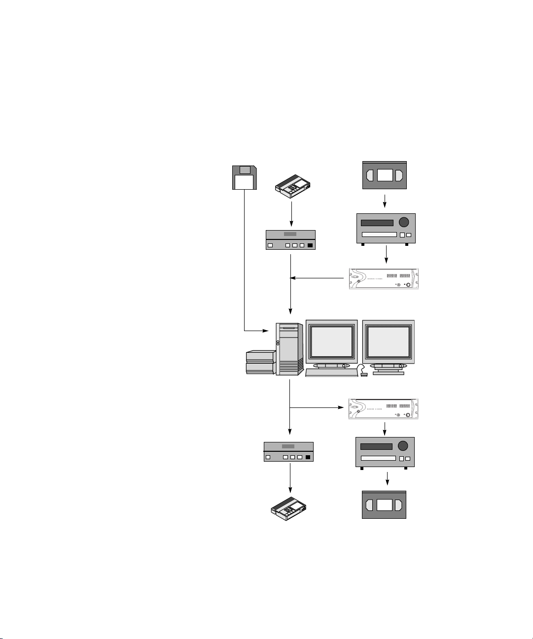
Sample Workflow
Figure 1 shows a possible workflow using a standalone configuration. If
you were in a workgroup environment, media can be brought in from, and
sent back to, shared storage.
Sample Workflow
1. (Option) Import a log file to
create a bin.
2. Connect your equipment.
For analog video, use the
Avid Adrenaline DNA
or Avid Mojo DNA. For the
software only model, use the
1394 connection on the Avid
editing system.
3. Capture the media in the
resolution you want. If you
imported a log file, batch
capture. Otherwise, log and
capture or capture on-the-fly.
4. Perform edits and create a
final sequence.
5. Output an analog or digital,
NTSC or PAL, master tape.
In a workgroup environment
you can send to air or post to
Web.
Software only models
Log
V
D
DV deck
or camera
1394 connection
1394 connection
DV deck
or camera
Beta-
cam
Source footage:
NTSC 30 fps or
PAL 25 fps
Betacam,
Digital Betacam,
or other VTR,
DV deck or
camera
Adrenaline DNA
or Mojo DNA
Avid editing
system
Adrenaline DNA
or Mojo DNA
Betacam,
Digital Betacam,
or other VTR, DV
deck or camera
V
D
Figure 1 Project Workflow
Betacam
25-fps or
30-fps master
29
Page 30

Chapter 1 Planning a Project
Video and Film Projects
Avid editing applications offer you a flexible approach to finishing your
project, whether it originates as video or film.
For video projects, you can use the offline capabilities of the Avid editing
application and the Total Conform capabilities of the Symphony system to
produce the highest quality, uncompressed broadcast masters.
For film and 24-fps or 25-fps HDTV (high-definition television) projects,
you can use the Avid editing application’s Universal Offline Editing
capabilities to capture footage at 24 fps or 25 fps, and edit the content in its
native frame rate. Then use the Symphony system’s film-tape-film-tape
(FTFT) and Total Conform capabilities to finish and deliver uncompressed
NTSC, PAL, 4:3, 16:9, and letterbox formats, as well as frame-accurate
film cut lists and edit decision lists (EDLs), all from the same 24p (24-fps
progressive) or 25p media.
30
Page 31

Chapter 2
Logging
When you log with a deck or import shot log files, you provide the Avid
editing system with frame-accurate clip information used to capture the
source footage. The logs you create form the foundation for organizing,
tracking, storing, retrieving, and generating lists of edit information
throughout your project. The following sections provide techniques for
preparing log information prior to capturing:
• Logging Tips
• Preparing Logs for Import
• Importing Shot Log Files
• Setting the Pulldown Phase
• Converting Log Files with Avid Log Exchange
• Logging Directly to a Bin
• Logging Film Information
• Modifying Clip Information Before Capturing
• Exporting Shot Log Files
Page 32

Chapter 2 Logging
Logging Tips
Logging Preroll
The following sections provide important guidelines for preroll, timecode
formats, and naming of tapes when logging prior to capturing.
Be sure to leave adequate preroll with continuous timecode prior to IN
points when logging your tapes. The recommended minimum preroll is
2 or 3 seconds for Betacam playback, 5 seconds for 3/4-inch U-matic
playback, and 6 seconds for DV playback.
To set the default preroll for tape playback:
1. Open the Deck Settings dialog box by doing one of the following:
t If no deck currently exists, double-click Deck Configuration in the
Settings scroll list to open the Deck Configuration dialog box,
click Add Channel and then click Add Deck.
32
t If a deck already exists, double-click Deck Configuration in the
Settings scroll list to open the Deck Configuration dialog box, and
then double-click the deck name.
t Select Tools > Capture to open the Capture tool, and then click the
Deck Selection pop-up menu, and select Adjust Deck.
Page 33

Preroll setting
Logging Tips
2. Click the Preroll pop-up menu, and select a preroll time.
Logging Timecode
Within an NTSC project, check the timecode format of each tape (dropframe versus non-drop-frame timecode) when you are logging without a
tape in the deck.
n
Drop-frame timecode and non-drop-frame timecode exist only in NTSC
projects.
33
Page 34

Chapter 2 Logging
To log drop-frame timecode when there is no tape in the deck:
1. Double-click Deck Preferences in the Settings scroll list.
The Deck Preferences dialog box opens.
Log As pop-up
menu
34
2. Click the Log As pop-up menu, and select Drop Frame. When you are
bringing in a bin created outside of the Avid editing system, use
semicolons (;) between the hours, minutes, seconds, and frames.
To log non-drop-frame timecode when there is no tape in the deck:
1. Double-click Deck Preferences in the Settings scroll list.
The Deck Preferences dialog box opens.
2. Click the Log As pop-up menu, and select Non-drop Frame. When you
are bringing in a bin created outside of the Avid editing system, use
colons (:) between the hours, minutes, seconds, and frames.
Page 35

Naming Tapes
Logging Tips
When you type tape names in the Capture tool, consider the following:
• It is important that you devise a naming scheme for your tapes. For
example, tapes with similar names can be easily sorted and viewed
together in a bin. However, it might be difficult to distinguish among
tapes with similar names when you try to locate a specific tape quickly.
Name tapes based upon the amount and complexity of your source
material.
• Tape names must be alphanumeric characters (A–Z, 0–9), with no
spaces before the name. They can include uppercase and lowercase
letters. Bin names are now limited to 27 characters (not including the
4 characters reserved for the file name extension).
• It is possible to have a single tape listed as several different tapes if you
alter the case of the letters. This can cause significant problems in
keeping track of clips. Choose a case convention and maintain it
throughout a project.
• If you are planning to generate an edit decision list (EDL) for import
into an edit controller for online editing, double-check the controller’s
specifications beforehand. Some edit controllers will truncate source
tape names to as few as six characters, while others will eliminate
characters and truncate to three numbers.
Double-Checking the Logs
When importing shot logs for video, the Avid editing system compares the
video duration to the video out minus the video in. When importing film
shot logs, the system compares the key number out minus the key number
in.
If the Avid editing application detects a discrepancy, it reports the error and
does not bring the clip into the bin.
To ensure that clips are not discarded on import:
t Double-check the logs for discrepancies in duration and marks.
35
Page 36

Chapter 2 Logging
Adding a Memory Mark
You can add a memory mark to a particular location on a tape. The Mark
Memory button in the Capture tool allows you to add one mark per tape.
The Go to Memory button allows you to move through the tape to the
marked location. You can clear the memory mark by using the Clear
Memory button.
The memory mark is not stored on the tape. When you remove the tape
from the deck, the mark is cleared.
36
Go to Memory button
Clear Memory button
Mark Memory button
Page 37

Preparing Logs for Import
Preparing Logs for Import
For Avid Log
Exchange information,
see “Avid Log
Specifications” in the
Help.
Avid editing applications provide many useful tools to help you prepare
frame-accurate log information for import to the bin from any number of
sources. This process might involve using a word processor or standard
text editor to create and import logs, including those using the Avid Log
Exchange (ALE) format.
Creating Avid Logs
You can prepare an Avid log on any Windows or Macintosh computer by
using a word processing application or a text editor. To ensure accuracy,
you must follow the Avid log specifications.
You can use any text editor to create Avid logs. However, you must save
the file as a text document (ASCII format).
Your Windows system ships with a text editor called WordPad. WordPad
can handle large files, and it allows you to save the files as text documents.
To start WordPad:
tClick the Start button, and select > All Programs > Accessories >
WordPad.
n
c
To create Avid logs by using a word processor:
1.Enter shot log information according to the specifications.
For Avid log specification information, see “Avid Log Specifications” in
the Help.
2. Save your file as a text file in the Save As dialog box.
Avid editing applications accept only text files (ASCII format).
When you are logging manually, document the following information:
• Identify the source tape for each shot.
37
Page 38

Chapter 2 Logging
• Document each clip’s name, start timecode, and end timecode.
This is the minimum information required to capture successfully. You can
also add other information such as comments or auxiliary timecodes. You
can make a separate log file for each videotape, or you can log clips from
several different videotapes into one log.
Importing Shot Log Files
You can import any log created or converted to meet Avid log
specifications. You can also combine or merge events while importing a
log so that fewer master tapes require capturing. The system imports any
additional information logged with each clip.
To import shot log files into a bin:
1. Open a bin, click anywhere in an open bin to select it, or create a new
bin for the shot log import.
2. Select File > Import.
38
The Select Files to Import dialog box opens.
Page 39

Files of type
pop-up menu
Options button
Preparing Logs for Import
Up One Level button
n
3. Do one of the following:
t Click the Files of type pop-up menu, and select Shot Log.
The system displays file types that belong to the selected category
only.
t Click the Files of type pop-up menu, and select All Files.
The system displays all files in a selected folder, regardless of file
type. Use this option if you want to batch import multiple file
types.
When batch importing multiple files and file types, you should establish
global Import settings in advance. See “Creating and Using Import
Settings” on page 202.
39
Page 40

Chapter 2 Logging
4. Click Options to open the Import Settings dialog box if you want to
select options for combining events on import from the Import
settings.
5. Click the Shot Log tab. For more information about shot log options,
see “Import Settings” in the Help.
40
6. After selecting the appropriate options, click OK to return to the Select
Files to Import dialog box.
7. Use the Up One Level button to locate the folder containing the source
file.
8. Select the file.
9. Click Open.
When the system finishes importing the file, the clips appear in the
selected bin.
Page 41

Setting the Pulldown Phase
Setting the Pulldown Phase
For information about
the pulldown process,
see “Transferring 24fps Film” in the Help.
Set Pulldown
Phase option
If you are logging or capturing 24-fps sources (film-to-tape transfers,
media downconverted from 1080p/24 footage, or both), you can set the
pulldown-to-timecode relationship for a transferred tape in the Film
Settings dialog box.
You set this relationship by selecting the pulldown phase (sometimes
called the pulldown frame or pullin frame), which is the video frame at
which the master clip starts. The pulldown phase is designated A, B, X, C,
or D. Film labs and transfer houses typically use the A frame to start the
transfer.
41
Page 42
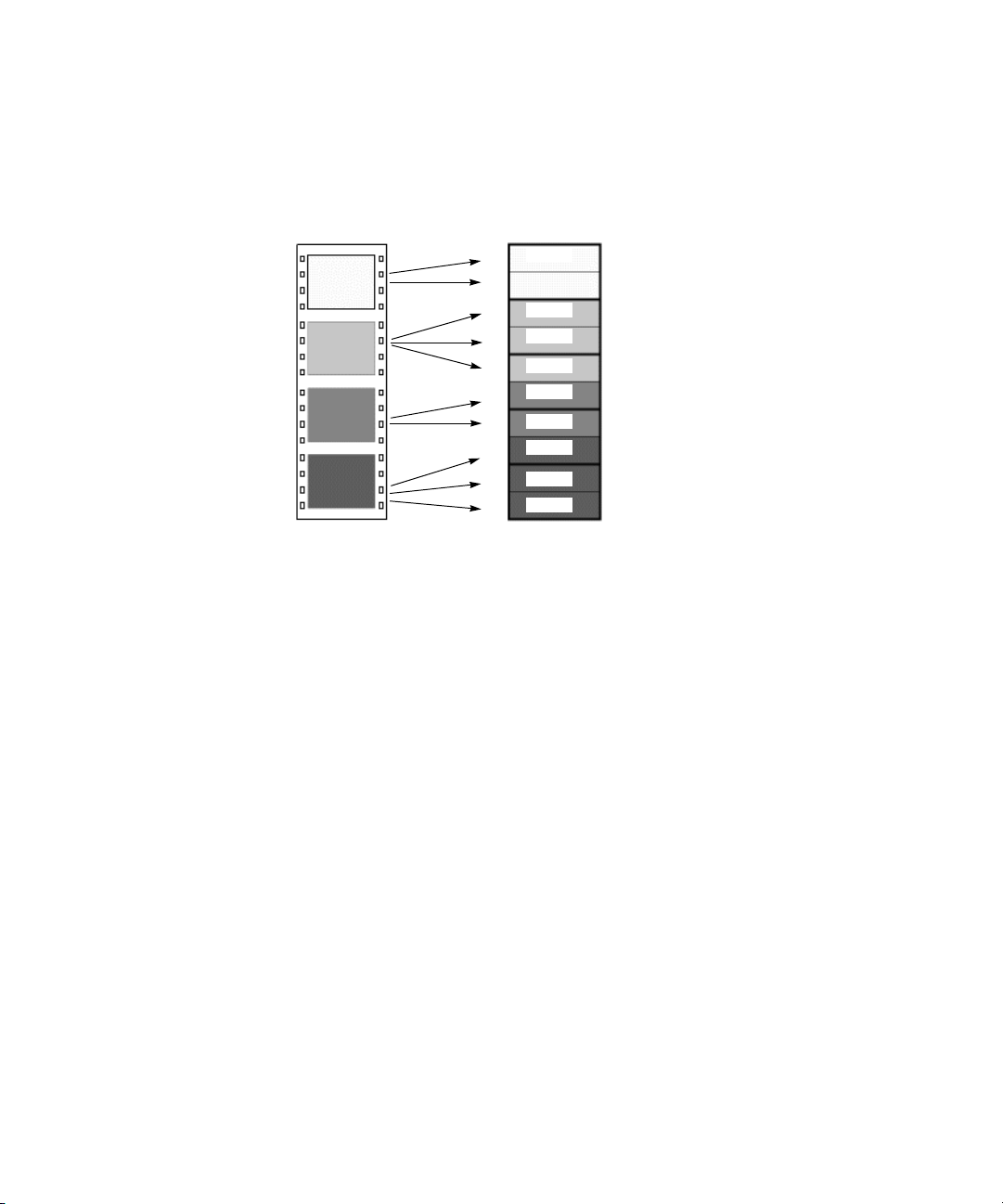
Chapter 2 Logging
The following illustration shows the relationship between film frames and
video frames.
n
Four film frames
A
B
C
D
Five NTSC video frames (ten fields)
odd
A1
A2
B1
B2
B3
C1
C2
D1
D2
D3
even
odd
even
odd
even
odd
even
odd
even
A
B
X
C
D
This setting is not available in matchback projects. However, you can
modify the pulldown phase after you log it. See “Entering Pulldown
Information” on page 60.
The Set Pulldown Phase setting lets you log, batch capture, and captureon-the-fly more easily, because the correct pulldown phase of any IN point
for a particular tape is automatically determined. Setting the correct
pulldown phase prevents inaccuracies in cut lists and matchback EDLs. It
also prevents incorrectly captured clips that appear to stutter when played
in 24p NTSC projects.
42
c
For example, if you set the pulldown phase of 00:00:00:00 as A (indicating
that the A frame is located at timecodes ending in 0 or 5), any timecode
you log will calculate its pulldown phase based on the same sync point,
regardless of where you set the IN point. If you use the Capture tool to log
a clip that starts at 01:00:10:01, the Avid system automatically enters B in
the Pullin column of the bin. If you capture on-the-fly starting at
01:00:10:01 (a B frame), the system begins to capture at the next A frame,
in this case, 01:00:10:05.
The Set Pulldown Phase feature does not work if you capture from a
mark IN.
Page 43

Converting Log Files with Avid Log Exchange
For information about
fixing an incorrectly
logged sync point, see
“Modifying the
Pulldown Phase After
Capturing” on
page 187.
The pulldown-to-timecode relationship might vary from tape to tape, or
within the same tape, depending on how the footage was transferred. If you
find that a tape requires a different pulldown phase, you can change the
setting in the Film Settings dialog box, or use the Modify Pulldown Phase
dialog box before capturing (see “Modifying the Pulldown Phase Before
Capturing” on page 63.
To set the pulldown phase:
1. Determine the correct pulldown phase for 00:00:00:00 in one of the
following ways:
t If you are capturing film-to-tape transfers, check the transfer log.
t If you are capturing tapes that have been downconverted from
1080p/24, check what pulldown frame was set for 00:00:00:00 on
the deck that performed the conversion.
t If you still cannot determine the pulldown phase, see
“Determining the Pulldown Phase” on page 62.
2. Double-click Film in the Settings scroll list of the Project window.
3. Select the option Set Pulldown Phase of Timecode 00:00:00:00 and
then click the pop-up menu, and select the correct pulldown phase
(A, B, X, C, D).
4. Click OK.
Converting Log Files with Avid Log Exchange
You can use the Avid Log Exchange (ALE) utility included with your
system to quickly convert shot log files created by other sources. You can
then import the files directly into bins, as described in “Importing Shot Log
Files” on page 38.
The ALE utility allows you to:
• Modify the text in a log file.
• Convert log files to the ALE file.
• Convert an ALE file to either an ATN or FLX file.
43
Page 44

Chapter 2 Logging
Any options you set in the ALE utility are saved each time you exit the
ALE utility.
When you are converting an ATN file that contains multiple sections to an
ALE file, multiple ALE files are created. The Avid Log Exchange window
displays only the first ALE file created. The succeeding ALE files are
given the same file name with incremental numbering. For example, the
file Nations1.atn is converted to Nations1.ale, Nations1_2.ale,
Nations1_3.ale, and so on. The converted output files are stored in the
folder containing the original input file.
n
ALE and tab-delimited files include information for master clips and
subclips only. Information for other objects, such as group clips,
sequences, and precomputes, is not included.
Converting a Log File to an ALE File
To convert a log file to an ALE file:
1. Click the Start button and select > All Programs > Avid > Avid Log
Exchange.
The Avid Log Exchange window opens.
2. Select File > Open.
The Open dialog box opens.
3. Browse to the file you want to convert and double-click it.
44
Page 45
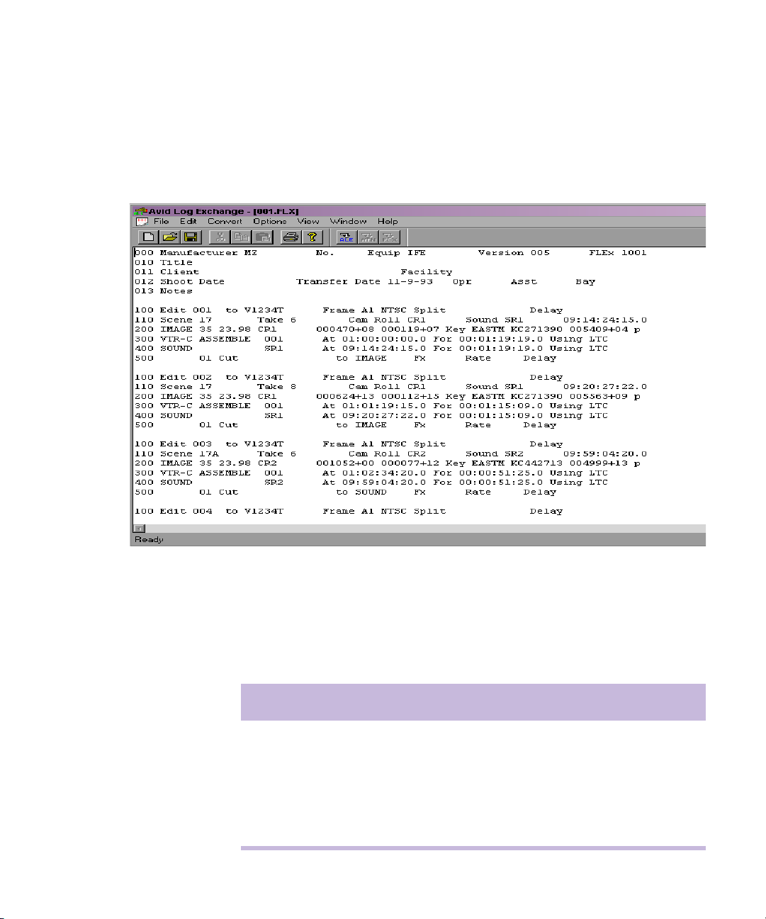
Converting Log Files with Avid Log Exchange
4. Depending on the type of file you are opening, one of the following
occurs:
- If the file type is recognized by Avid Log Exchange, the file
appears in the Avid Log Exchange window.
- If the file does not contain the Windows line-ending format, then
the Line Endings dialog box opens. Select one of the following
options as explained Table 2 :
Table 2 Line Endings Options
Click To
Display & Save Open the file in the Avid Log Exchange window and
change the file to the Windows format.
Display Only Open the file in the Avid Log Exchange window, but do
not change the file.
Ignore Display the file without changes.
45
Page 46
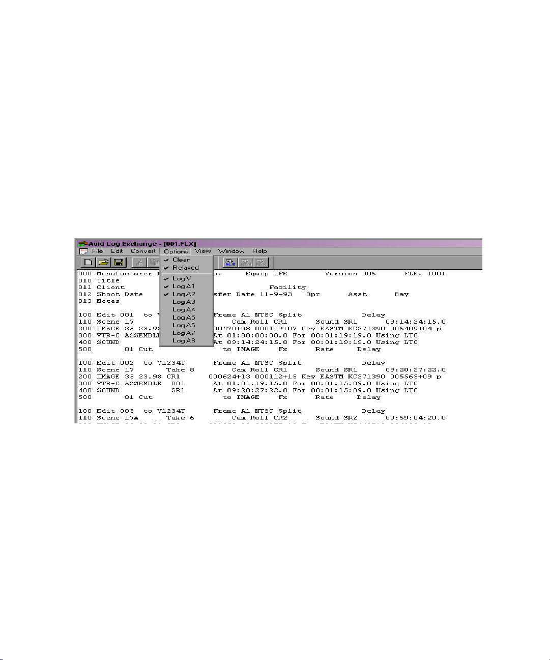
Chapter 2 Logging
The file appears in the Avid Log Exchange window.
For specific
information on the file
types shown here, see
“Avid Log
Specifications” in the
Help.
- If the file type is not recognized, the Choose File Type dialog box
opens. Select the type of file you are converting, and click OK.
The file appears in the Avid Log Exchange window.
5. Use the Options menu to select the tracks to include in the Tracks
column of the log. The default track selections are Log V, Log A1, and
Log A2.
After you import the log into an Avid bin, the system captures all
tracks shown in this column when batch capturing.
46
6. Select Options > Clean if you want Avid Log Exchange to clean the
ALE output file to eliminate overlapping timecodes for clips. By
default, Clean is selected.
When you select Clean, the utility removes the end timecode from any
clip that overlaps the start of the next clip.
7. If you selected Clean, you can also select Options > Relaxed to prevent
deleting events that come earlier in the transfer. Relaxed is not set by
default.
For example, if you transfer film footage with a timecode of
2:00:00:00 and then add some clips at the end with a timecode of
1:00:00:00, Relaxed prevents the Clean function from deleting the
Page 47
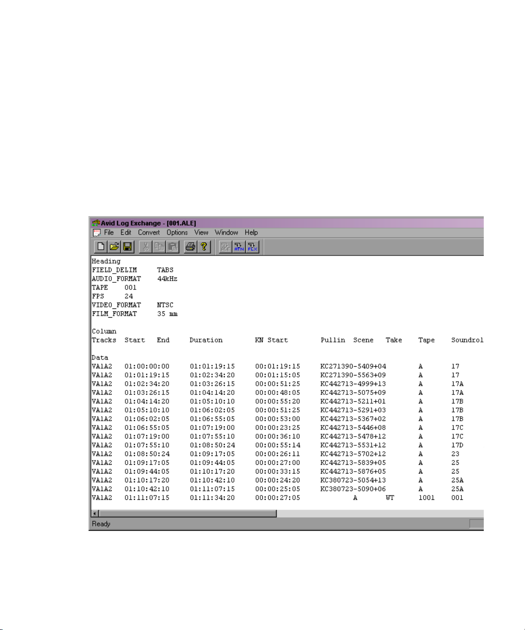
Converting Log Files with Avid Log Exchange
clips. This occurs when you shoot footage across the midnight hour
and the first half of the film has 24 hours and the second half has 0
hours.
8. Select Convert > ALE.
The default output selection is the Avid Log Exchange (ALE) format.
This is the required format for import into an Avid bin.
The Avid Log Exchange window displays the converted ALE file. The
converted file has the same file name as the original file, except the file
name extension matches the converted file format.
9. (Option) Select Window > original file if you want to convert the file
again, using different options.
47
Page 48

Chapter 2 Logging
10. Select File > Close.
If you made changes in the editor, a message box opens.
11. Click Yes.
The converted file is stored in the same folder as the original log file.
Using Drag-and-Drop Conversion
Use this shortcut to convert any type of file into an ALE file.
n
Before you use the drag-and-drop conversion, check the options in the ALE
utility. The current options are used when you perform the drag-and-drop
conversion.
To convert a log file by using drag-and-drop conversion:
1. Create a shortcut for the ALE utility.
2. Open the folder that contains the files you want to convert, positioning
the folder so the Shortcut icon for the ALE utility is visible.
48
Page 49

Converting Log Files with Avid Log Exchange
3. Select the files you want to convert.
Avid Log Exchange
Shortcut icon
4. Drag the selected files to the Shortcut icon for the ALE utility, and
release the mouse button.
5. Depending on the type of files you are converting, one of the following
occurs:
- If the file type is recognized by the ALE utility, a message box
opens, indicating the conversion was successful.
- If the file type is not recognized, the Choose File Type dialog box
opens. Select the type of the file you are converting, and click OK.
A message box opens, indicating the conversion was successful.
- If the file type is an ALE file, the ALE Convert Type dialog box
opens. Select a file type for the converted output file, and click
OK.
A message box opens, indicating the conversion was successful.
49
Page 50

Chapter 2 Logging
6.Click OK to close the message box.
The converted files have the same file names as the original files,
except the file name extension matches the converted file format.
For example, the .ale file name extension is added to the new file
names for the Avid format. The converted files are stored in the folder
containing the original log files.
Logging Directly to a Bin
You can log clips directly to a bin by using the Capture tool in one of two
ways described in this section:
For complete
information on working
with bin columns and
clip information, see
“Organizing Bin
Information in the
Help.
• Log directly to a bin with an Avid-controlled deck for semiautomated
data entry.
• Log manually during or after viewing of footage offline with a nonAvid-controlled deck or other source.
Logging with an Avid-Controlled Camera or Deck
When you log with a DV camera or compatible video deck controlled from
within your Avid editing application, you can automate part of the logging
process by using buttons to enter frame-accurate timecode information
from the camera or deck. This method is more accurate than manual entry
because timecodes are transferred directly from tape to the bin.
To log clips to a bin by using the Capture tool:
1. Make sure the camera or deck is properly connected, and turn on
power to the video deck.
2. Open the bin in which you want to store the clips.
50
Page 51

Mark IN
button
Channel
Selection buttons
Deck Selection
pop-up menu
Source Tape
Display button
Logging Directly to a Bin
3. Select Tools > Capture.
The Capture tool opens.
Capture/Log Mode button
51
Page 52

Chapter 2 Logging
4. To select a deck or device, click the Deck Selection pop-up menu and
select Autoconfigure or Adjust Deck, and then load your tape into the
deck.
The Select Tape dialog box opens.
52
5. Do one of the following:
t Click Cancel to stop the process at any time.
t Select “Show other projects” to display the tape names and
associated project names for all bins that have been opened in the
current session.
t Click “Scan for tapes” to scan the system and display tape names
and associated project names for all media files that are currently
online (drives that are currently mounted on the system).
6. Click the Capture/Log Mode button in the Capture tool until the LOG
icon appears.
7. Click the Source Tape Display button.
A dialog box opens.
8. Click Yes to open the Select Tape dialog box.
Page 53

Logging Directly to a Bin
9. Double-click the name of the tape in the dialog box, or click New and
type the name of the tape. Click OK.
A message that the system is waiting for you to mark an IN point is
displayed in the message bar.
10. Set the first point by using one of the following methods:
Mark IN
Mark IN
Mark OUT
Go to IN
Go to OUT
Mark OUT
and Log
n
t Click the Mark IN button in the upper left corner of the Capture
tool or press F4.
t Use the deck controls in the Capture tool to cue your source tape to
the start or end point, and click the Mark IN or the Mark OUT
button.
t If the footage starts at a known IN point or ends at a known OUT
point, type the timecode in the text box next to the Mark IN or the
Mark OUT button. Then enter the mark by pressing the Go to IN
or the Go to OUT button, which scans the tape forward to the
mark, or by pressing Enter.
After you set the point, the Mark IN button changes to either the Mark
OUT and Log or the Mark IN and Log button.
If you want to pause the deck while you enter a clip name and comments,
see “Pausing a Deck While Logging” on page 54.
11. To finish logging the clip, do one of the following:
t Set the remaining IN or OUT point on-the-fly by using the Mark
IN or Mark OUT buttons, or by pressing F4.
t Type a timecode for the clip’s IN point, OUT point, or duration in
the timecode text boxes next to the corresponding icon, and press
Enter.
c
The system automatically calculates the appropriate timecode for the
remaining IN point, OUT point, or duration, and enters the clip into the
bin. The clip name, which is automatically numbered by the system, is
highlighted and ready to be changed.
You must enter two of the three timecode marks (IN point, OUT point,
or duration) to complete the log entry.
53
Page 54

Chapter 2 Logging
12. Name the clip by typing a new name before clicking any of the buttons
in the Capture tool.
n
n
Consider changing the clip name immediately because it is easy to forget
the contents of each clip if you are logging many clips. You can, if
necessary, accept the clip name, proceed with the logging process, and
then change the clip names in the bin at a later time.
13. Repeat these steps until you have logged all your clips.
While viewing the footage, you can continuously update your marks onthe-fly by clicking the Mark IN or the Mark OUT button repeatedly before
entering the second mark.
Pausing a Deck While Logging
If the deck is playing while you log clips, you can direct the Avid editing
application to pause the deck automatically after you select an IN point and
an OUT point. While the deck is paused, you can enter the name and a
comment for the clip you want to log.
To pause the deck while logging:
1. Double-click Capture in the Settings scroll list.
The Capture Settings dialog box opens.
54
2. Select the “Pause deck while logging” option.
Page 55

Mark IN button
Logging Directly to a Bin
3. Set up the deck and the Capture tool as described in “Logging with an
Avid-Controlled Camera or Deck” on page 50.
4. Start the deck.
5. When you reach the point where you want to start the clip, click the
Mark IN button in the upper left corner of the Capture tool (or press
the F4 key). The Mark IN button changes to the Mark OUT button, and
the deck continues to play.
6. When you reach the point where you want to end the clip, click the
Mark OUT button in the upper left corner of the Capture tool (or press
F4 again). The Mark OUT button changes to the Log Clip button, and
the deck pauses.
7. (Option) Type a clip name and comment.
8. Click the Log Clip button (or press F4).
The system logs the clip in a bin, and the deck starts playing again.
55
Page 56

Chapter 2 Logging
Logging with a Non-Avid-Controlled Camera or Deck
You can use the Capture tool to log clips directly to a bin from a source that
is not Avid-controlled. For example, you can log clips from a camera or
deck that is not connected to the system or from handwritten or printed log
information for a tape that was previously logged but is not currently
available.
n
When logging with the Capture tool, you should leave the deck empty. If a
tape remains in the deck, the system determines drop-frame or non-dropframe from that tape, whether or not it matches your tape’s timecode
format.
To log with a non-Avid-controlled camera or deck:
1. If there is a camera or deck connected to the system, eject the tape
from the deck.
2. Double-click Deck Preferences in the Settings scroll list.
The Deck Preferences dialog box opens.
3. For NTSC projects, click the “When no tape in deck log as” pop-up
menu, and select Non-Drop-Frame or Drop-Frame.
4. Click OK to close the dialog box.
5. Open the bin where you want to store the clips.
56
Page 57
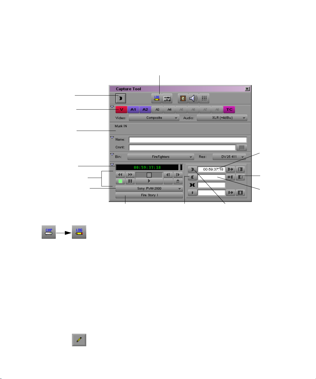
Mark IN
button
Logging Directly to a Bin
6. Select Tools > Capture.
The Capture tool opens.
Capture/Log Mode button
Channel
Selection
buttons
Message
bar
Timecode
display
Deck controls
Deck Selection
pop-up menu
Mark IN text
box
Clear OUT
button
Mark OUT
text box
Source Tape Display button Mark OUT button Mark IN button
7. Click the Capture/Log Mode button in the Capture tool until the LOG
icon appears.
8. Click the Source Tape Display button.
A dialog box opens.
9. Click Yes to open the Select Tape dialog box.
10. Double-click the name of the tape in the dialog box, or click New and
type the name of the tape. Click OK.
11. Select the tracks that you want to log, using the Channel Selection
buttons.
12. Type the start and end timecodes in the Mark IN and Mark OUT text
boxes.
13. Click the Log Clip button.
The clip is logged to the bin.
57
Page 58

Chapter 2 Logging
Logging Film Information
Once you have entered or imported the basic log information into a bin,
you might want to add film-related log information before capturing. This
section describes procedures and formats for adding various film headings.
The following are some important requirements for film-based projects:
• The minimum information required for capturing is the data recorded
in the Start and End video timecode columns, and the pulldown phase
for NTSC transfers, which is noted in the Pullin column (24-fps
capture only).
• Each reel of film can be logged as a separate clip, and will correspond
to a single master clip, only if the video transfer of the film reel has
continuous pulldown (NTSC format), and continuous timecode (NTSC
and PAL). If the film reels for your project do not meet this condition,
then you must log each take on a reel of film as a separate clip, which
will correspond to a single master clip.
If you log each reel as a separate clip, you can use the F1 and F2 keys
to create subclips for each take. See “Creating Subclips On-the-Fly” on
page 160.
58
• If you want to produce a cut list, or use film-tape-film-tape for
recapturing, you must log key numbers. You can add key numbers after
capturing, before you create the cut list.
• All film and video reference numbers must be in ascending order.
Page 59

Displaying Film Columns
To display film columns in the bin:
1. Click the Bin View pop-up menu, and select Film to display all the
required film column headings. The Bin View pop-up menu is located
at the bottom of the Bin window.
Bin View pop-up menu
Logging Film Information
2. To log data under optional headings (such as Ink Number, Auxiliary
TC1-Auxiliary TC5, or Film TC), select Bin > Headings and
Ctrl+click (Windows) or click (Macintosh) the specific headings you
want to add from the Bin Column Selection dialog box.
59
Page 60
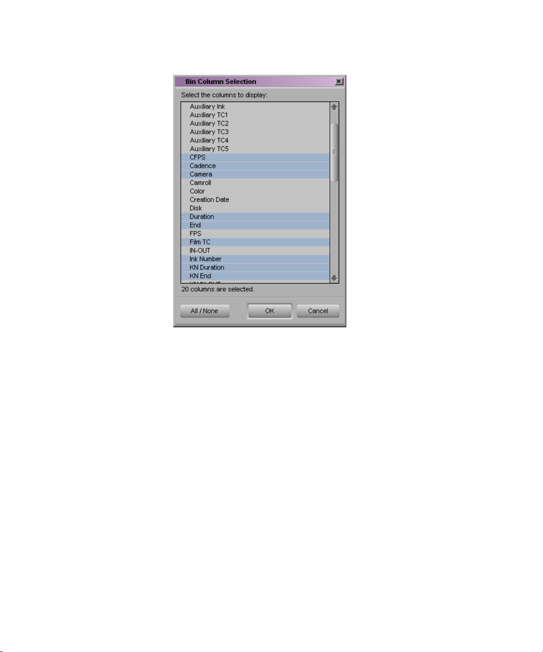
Chapter 2 Logging
3. You can also track custom information for the job by creating a custom
heading. To create a new heading, type a name that describes the
information in the headings bar at the top of the bin. For more
information on customizing bin views, see “Customizing Bin Views in
Text View” in the Help.
Entering Pulldown Information
For information about
importing a log file, see
“Importing Shot Log
Files” on page 38.
60
To accurately capture NTSC transfer tapes in 24p projects, you need to
enter pulldown information into the bin. (This information is not required
for PAL transfer tapes.) Setting the correct pulldown phase prevents
inaccuracies in cut lists and matchback EDLs. If you are importing a log
generated during the telecine transfer, the pulldown information is
automatically included in the bin.
Page 61
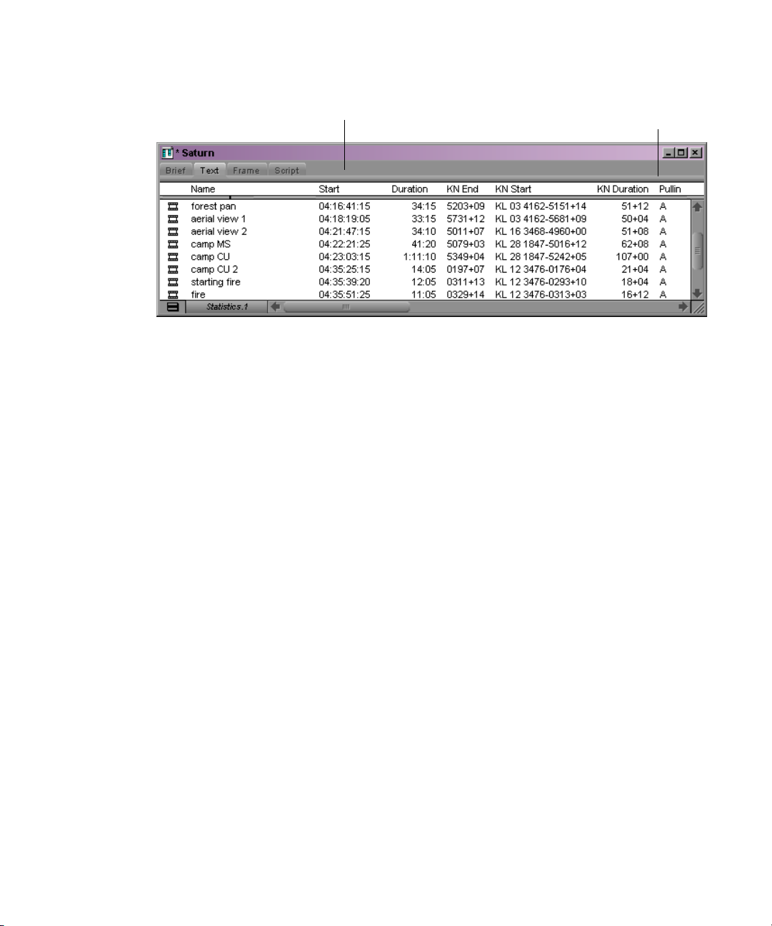
Logging Film Information
n
Start timecode
If you do not have a transfer log, or if the transfer log is incorrect, you need
to add the information manually. If you log clips by using the Capture tool,
the Avid system uses the A frame as the default pulldown phase. You might
need to edit this value.
For 24p projects, you can set a default pulldown phase in the Film Settings
dialog box. See “Setting the Pulldown Phase” on page 41 (24p projects
only).
Pullin column
(information required for NTSC
n
For matchback projects, you need to log key-number information before
you can log pulldown information.
By specifying the pulldown phase in the Pullin column, you accomplish
the following:
• You ensure that the clips will start with the correct frame for the
pulldown. Otherwise, you might experience inaccuracies in keynumber tracking and in the cut lists.
• You indicate where the pulldown fields are located so the Avid system
can accurately eliminate the pulldown fields during the capturing
process, leaving you with a frame-to-frame correspondence between
your digital media and the original 24-fps footage (24p projects only).
To do this, you must indicate whether the sync point at the start of each
film clip transferred to tape is an A, B, C, or D frame, as described in this
section. In most cases, the sync point is the A frame.
61
Page 62

Chapter 2 Logging
Determining the Pulldown Phase
It is easiest to determine the pulldown of a sync point (or pulldown phase)
if you ask your film lab to keypunch (cut a small hole in) the sync frame at
the zero frame in the original film footage before transferring the film to
video. Many film labs or transfer houses can also provide a pulldown
frame indicator displayed at the far right of the burn-in key numbers,
depending on the equipment available. Ideally, the A-frame pulldown
coincides with timecode ending in 0 and 5 (:00, :05, :10, and so on).
If the footage has not been keypunched, you can determine pulldown
according to clapsticks or any other distinctive frame at the beginning of
the clip. Determining the pulldown is easier if the frames depict motion.
n
For instructions on determining the pulldown phase for material already
captured, see “Modifying the Pulldown Phase After Capturing” on
page 187.
To determine the pulldown phase:
1. While viewing the video transfer on a monitor, go to the keypunched
(or clapsticks) sync point for the beginning frame of the clip you’re
logging.
2. Step (jog) past the sync point frame field-by-field, using the step wheel
on the tape deck. You will see either two or three keypunched fields. If
the footage is not keypunched, look for two or three fields with little or
no motion.
3. If there are two fields, the pulldown is either A or C. Step through the
fields again, and note where the timecode changes:
- If the timecode does not change from the first to the second field,
the fields came from an A frame.
- If the timecode changes from the first to the second field, the fields
came from a C frame.
The following illustration shows a keypunch on the A frame. Notice
where the timecode changes.
62
Page 63
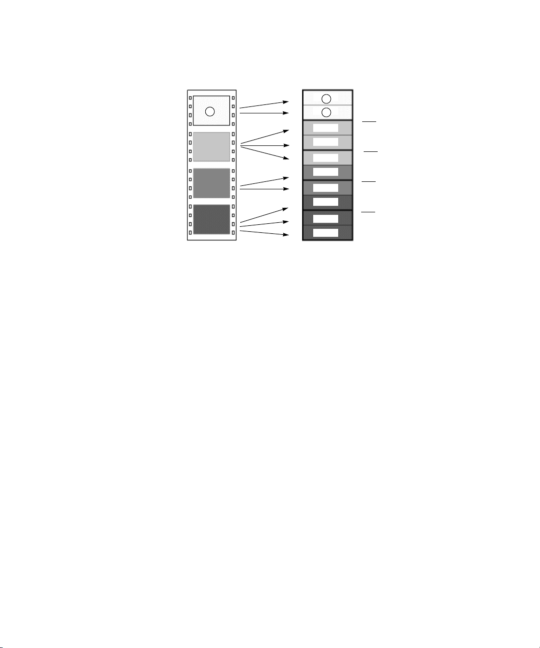
Logging Film Information
Four film frames
A
B
C
D
Five NTSC video frames (ten fields)
odd
even
odd
even
odd
even
odd
even
odd
even
A
Timecode change
B
Timecode change
X
Timecode change
C
Timecode change
D
A1
A1
A2
B1
B2
B3
C1
C2
D1
D2
D3
4. If there are three keypunched fields, or fields without motion, the
pulldown is either B or D. Step through the fields again and note where
the timecode changes:
- If the timecode changes from the second to the third field, the
fields came from a B frame.
- If the timecode changes from the first to the second field, the fields
came from a D frame.
5. Enter or edit the information in the Pullin column in the appropriate
bin, as described in the next section.
Modifying the Pulldown Phase Before Capturing
After you determine the correct pulldown phase (as described in the
previous section) you can modify the pulldown phase before capturing in
one of the following ways.
To modify the pulldown phase directly in the Pullin column:
1. Click the Text tab to display all bin information.
2. Click the cell you want to modify.
3. Click the cell again. The pointer changes to an I-beam.
4. Type the pulldown phase and press Enter (Windows) or Return
(Macintosh).
63
Page 64

Chapter 2 Logging
To modify the pulldown phase for multiple clips:
1. Ctrl+click (Windows) or Shift+click (Macintosh) the clips you want to
modify.
2. Select Clip > Modify.
3. Click the Modify Options pop-up menu, and select Pull-in.
4. Select A, B, C, or D.
5. Click OK.
The pullin for all selected clips is changed, based on the pulldown
phase you selected.
To modify the pulldown phase for multiple clips that have the same
pulldown-to-timecode relationship:
1. Ctrl+click (Windows) or Shift+click (Macintosh) the clips you want to
modify.
2. Select Clip > Modify Pulldown Phase.
The Modify Pulldown Phase dialog box opens.
64
3. Click the pop-up menu, and select the correct pulldown phase for
timecodes ending in 0 or 5.
4. Click OK.
The pulldown phase for each selected clip is changed, based on the
pulldown phase you selected for 00:00:00:00.
The Pulldown Phase setting also appears in the Film Settings dialog
box (24p projects only). You can override that setting with the Modify
Pulldown Phase dialog box. The selection in the Film Settings dialog
box remains the same. For more information, see “Setting the
Pulldown Phase” on page 41.
Page 65

Logging Film Information
n
n
If you want to modify the pulldown phase after capturing, you must first
unlink the clips. See “Modifying the Pulldown Phase After Capturing” on
page 187.
After you capture an NTSC transfer, the timecode shows a loss of every
fifth frame of video. For example, don’t be alarmed if you find that your
timecode jumps at one point from 1:00:14:15 to 1:00:14:17. You haven’t
lost a frame, just an extra pulldown field.
Entering Frames-per-Second Rates for PAL Transfers
When you log in advance for PAL film-to-tape transfers, you must log the
footage as clips that have a 25-fps play rate, as listed in the FPS column of
the bin. If you want, you can capture the footage on-the-fly, without
logging the clips first. The minimum information required to capture the
footage is the data logged in the Start and End video timecode columns.
Entering Key Numbers
To add key numbers:
t Highlight the KN Start column, then type the key number for the sync
point at the start of the clip by using one of the following formats:
- Keykode
type code, a six-digit prefix for identifying the film roll, a fourdigit footage count, a two-digit frame offset, and then press Enter
(Windows) or Return (Macintosh).
™
Format: Type a two-character manufacturer and film-
The Avid system adds a space, hyphen, and either a plus sign (for
35mm projects) or an ampersand (for 16mm projects) to format
the number. For example, in a 35mm project, to enter
KJ 23 6892-1234+15, type KJ236892123415. In a 16mm project,
typing the same number results in the code KJ 23 6892-1234&15.
65
Page 66

Chapter 2 Logging
- Other Formats: Enter other key-number formats in the Ink
Number column. Type up to eight characters for the prefix, up to
five characters for the footage count, two digits as the frame count,
and then press Enter (Windows) or Return (Macintosh).
The Avid system automatically calculates the ending key number
(KN End), based on the timecode duration.
c
Make sure the correct number appears when you press Enter
(Windows) or Return (Macintosh). For key-number formats other
than Keykode, you might need to type the space, hyphen (-), and plus
sign (+) or ampersand (&) to format the number correctly.
Entering Additional Timecodes (Option)
Consider the following when you enter additional timecodes:
• In one of the Aux TC columns (that is, Aux TC1 through Aux TC5),
type an auxiliary timecode that syncs with the video timecode logged
in the Start column. You can enter up to five auxiliary timecodes.
Supported timecodes depend on your project: 30-fps for NTSC (dropframe or non-drop-frame) and 25-fps for PAL. Use one of the
following formats:
t Enter a two-digit format for hours, minutes, seconds, and frames.
You need not enter a leading zero. (For example, to enter
01:23:02:00, type 1230200.)
t When working with drop-frame timecode in the NTSC format (not
applicable to PAL), enter a semicolon to indicate drop-frame
timecode (for example, to enter 01;23;02;00, type 01;230200).
66
• In the Sound TC column, enter the Nagra or DAT timecode for the
original audio for the start of the clip. The timecode should sync with
the video timecode logged in the Start column in the bin. Enter the
source sound-roll identifier in the Soundroll column. Supported
timecodes depend on your project: 30-fps for NTSC (drop-frame or
non-drop-frame) and 25-fps for PAL. The clip to be captured must
contain an audio track.
Page 67

Logging Film Information
• In the Film TC column, enter timecode generated by a film camera
(using Aaton or Arri timecode) for tracking the picture at the start of
the clip. The film timecode should sync with the video timecode
logged in the Start column. Only 24-fps timecode is supported. The
clip to be captured must contain a video track.
• In the TC24 column, enter timecode for original HDTV sources
(1080p/24) or audio DATs created for PAL feature film productions
that use in-camera timecode.
n
You can use the Duplicate command to convert timecodes from one format
to another. For more information, see “Duplicating a Column” in the
Help.
Entering the Ink Number (Option)
To enter ink numbers:
1. Open the Film Settings dialog box by clicking Film in the Settings
scroll list of the Project window.
2. Make sure the correct options are selected for ink number format and
ink number display, and click OK.
n
You can log different ink number formats in the same project as long as you
change the ink number setting to the appropriate format before you log
each type. Changing the ink number setting affects only the next ink
numbers you log, not numbers that are already logged.
3. Return to the bin and enter numbers under the Ink Number heading.
For example, use Keykode format or use a two-digit prefix to identify
the roll, a hyphen, a four- or five-digit footage count, a plus sign, and a
two-digit frame count (for example, AA-00924+00).
Entering Additional Film Data
You can continue to log additional film data into the Labroll, Camroll,
Soundroll, Scene, and Take columns, or into your own custom columns, as
necessary. You can include the information in these columns on the cut
lists you create for your edited sequence.
67
Page 68

Chapter 2 Logging
Modifying Clip Information Before Capturing
The following conditions apply to modifying clip information:
• When you modify a clip’s information, related objects are
automatically updated to reflect the new data. For example, if you
change the name of a clip, the updated name appears in the sequences
that use the clip.
• Some data cannot be modified after capturing because changes would
prevent you from playing back and editing the material successfully.
• Sequence information cannot be changed even though it appears in
your bin. The only way to modify sequence information is to edit the
sequence itself. You can, however, change the name and start time for
the master timecode track.
You can modify some data directly for master clips, subclips, and other
objects stored in a bin.
The Modify Command
The Modify command gives you specialized control over groups of clip
information. For example, you can use the Modify command to change the
name of source tapes for some or all of your clips, to change the timecode
format from drop-frame to non-drop-frame, or to increment or decrement
the start and end timecodes by a specified length of time for one or several
clips at once.
You can apply changes with the Modify command to master clips only;
subclips and sequences cannot be altered in this way. In addition, you can
perform only modifications that alter the end timecodes or the tracks
before capturing.
68
Page 69

Using the Modify Command
To modify selected clips:
1. Open the bin.
2. Click a Clip icon to select it. Ctrl+click each additional clip you want
to modify.
Selected clip is
highlighted.
3. Select Clip > Modify.
The Modify dialog box opens.
Modifying Clip Information Before Capturing
Pop-up menu
4. Click the pop-up menu, and select an option (for example, Set
Timecode By Field).
Depending on the modification you select, different options appear in
the dialog box that allow you to establish the specific modification, as
shown in Tabl e 3 .
69
Page 70

Chapter 2 Logging
5. After selecting the type of modification, select an option or type
information in the text boxes (for example, timecode values) when
they appear.
6. Click OK.
The modification takes effect.
Options for Modifying Bin Information
Table 3 describes the options available from the pop-up menu in the
Modify dialog box.
Table 3 Options for Modifying Bin Information
Type of Modification Options Description
Set Timecode
Drop/Non-drop
Set Timecode By Field Start or End Changes either the start or end timecode. Only
Increment Timecode Start or End Changes either the start or end timecode.
Drop, Non-drop Changes the timecode format between drop-
frame and non-drop-frame. Setting must
match the timecode format of the tape.
start timecode can be altered after capturing.
Hour, Minutes, Seconds,
Frames
Timecode entry field Allows you to enter custom incremental
Allows you to enter custom timecode.
Incrementing the start timecode automatically
modifies the end timecode by the same
amount. Only start timecode can be
incremented after capturing.
timecode.
70
Page 71

Modifying Clip Information Before Capturing
Table 3 Options for Modifying Bin Information (Continued)
Type of Modification Options Description
Decrement Timecode Start or End Changes either the start or end timecode.
Decrementing the start timecode
automatically modifies the end timecode by
the same amount. Only start timecode can be
decremented after capturing.
Timecode entry field Allows you to enter new decremental
timecode.
Set Key Number Generic
(Prefix)
Set Pullin Punch frame timecode entry
Set Tracks V, A1, A2, A3, A4, A5, A6,
Set Source None Opens the Select Tape dialog box. Selects
Key number field Allows you to enter a custom generic key
number (film projects only).
Sets the timecode location of the punch frame
field
A, B, C, or D Selects the pulldown frame to match the
A7, A8 track selector
for pullin (film projects only).
timecode entry (film projects only).
Changes the clip’s configuration of tracks.
The number of audio tracks varies
n
depending on the hardware that is
connected to your system.
another source tape name for the clips. Should
match the original source tape name.
Modifying in the Bin
You can modify the start and end timecodes in the bin before a clip is
captured.
To modify clip information in the bin:
1. Set the bin to display Start and End. For more information about
setting bin headings, see “Showing and Hiding Columns” in the Help.
2. Select the clip you want to modify.
3. Type the timecode numbers you want.
71
Page 72

Chapter 2 Logging
Exporting Shot Log Files
You can export a shot log file from the Avid editing system in either Tab
Delimited or Avid Log Exchange format for making adjustments in a text
editor or for importing to another system.
To export a shot log based on clip information in a bin:
1. Open the bin containing the clips you want to export, and switch to
Text view.
2. Click a Clip icon to select it. Ctrl+click each additional clip you want
to export.
3. Select File > Export.
The Export As dialog box opens.
72
4. Do one of the following:
t If you have previously created an Export setting for exporting shot
log files, click the Export Setting pop-up menu, and select the
setting. Then go to step 11.
For information on creating Export settings, see “Customizing
Export Settings” on page 276.
t If you want to create a new Export setting, go to step 5.
Page 73

Exporting Shot Log Files
5. Click Options.
The Export Settings dialog box opens.
6. Click the Export As pop-up menu, and select either Avid Log
Exchange or Tab Delimited as the file type.
7. Click Save As.
8. Type a name in the Setting Name text box.
The export setting name is added to the list of formats available from
the Export dialog box.
9. Click OK.
You are returned to the Export As dialog box.
10. (Option) Change the file name, but keep the default file name
extension.
11. Select the destination folder for the file, and click Save.
The file is exported and appears at the selected destination.
To export an entire bin:
1. Ctrl+click selected clips to deselect them, so that nothing is selected in
the bin.
2. Select File > Export.
The Export Bin As dialog box opens.
3. Click the Export Bin As pop-up menu, select the appropriate option,
and click OK.
A shot log of only the master clips in the bin is created.
73
Page 74

Chapter 2 Logging
74
Page 75

Chapter 3
Preparing to Capture
Capture is the process of creating digital media from videotape or audio
input. Before you begin the capturing process in Chapter 4, you need to
prepare for it as described in the following sections:
• Understanding Digital Video (DV)
• Preparing the Hardware
• Selecting Settings
• Configuring Decks
• Understanding Drop-Frame and Non-Drop-Frame Timecodes
• Setting Up the Capture Tool
• Preparing for Audio Input
• Audio Meters in the Timeline
• Adjusting Volume Control
• Calibrating for Video Input
• Compression Resolutions and Storage Requirements
Before capturing, see the Avid Using the Avid Adrenaline DNA Installation
Instructions or Avid Using the Avid Mojo DNA Installation Instructions to
ensure you have properly connected your recording equipment such as a
camera or deck.
Page 76

Chapter 3 Preparing to Capture
Understanding Digital Video (DV)
DV refers to digital video that is transferred through equipment
conforming to the Institute of Electrical and Electronics Engineers (IEEE)
Standard 1394. This equipment (cameras, decks, cables, connectors, and
processing boards) is sometimes referred to as FireWire or i.LINK.
DV connections let you transfer digital data (both video and audio) directly
from a DV camera to a digital nonlinear editing system with no conversion
losses. DV technology simplifies the process of bringing footage from your
camera into your Avid editing application, and gives you high-quality
video at low lost.
What Is IEEE Standard 1394?
IEEE 1394 is an internationally standardized, low-cost digital interface that
integrates entertainment, communication, and computing electronics into
consumer multimedia. IEEE 1394 is a hardware and software standard for
transporting data at 100, 200, or 300 megabits per second (Mb/s). Because
it’s a digital interface, there is no need to convert digital data into analog,
resulting in a loss of data integrity.
76
n
What Is OHCI?
The Open Host Controller Interface (OHCI) specification gives the
operating system a standardized way of interacting with the 1394 bus. An
IEEE 1394 interface that conforms to this specification can provide a
connection between a computer and a DV camcorder that will operate in a
standard way, using driver software that is included with the latest version
of the Windows XP operating system.
Avid software-only editing systems use a custom OHCI driver, rather than
the default Microsoft OHCI driver. Whenever you connect a new DV device
(camera or deck), Avid editing applications automatically link the device to
the custom OHCI driver.
Page 77

Preparing the Hardware
Before you begin capturing, check the following:
• Remote switch. The deck control switch on the front of the source
deck must be set to Remote rather than Local to control the deck with
the Capture tool.
Preparing the Hardware
n
The deck should be turned on and the control switch set to Remote before
you start the Avid editing application.
• Striped drives. If you are capturing high-resolution media, you must
use striped drives.
• Digital Audiotape (DAT). If you want to capture music or audio from
a DAT deck, check the documentation supplied with your equipment to
determine whether your model requires VLX
Selecting Settings
A number of settings have a direct bearing on the capturing process.
Before you capture, review the following options:
• Using General Settings
• Transfer Settings for Film Projects
• Selecting Capture Settings
• Creating a GPI Trigger
®
i for video deck control.
Using General Settings
The General Settings dialog box (accessed through the Settings scroll list)
includes the following options that are important for capture.
• Project Type: The top portion of the dialog box displays the project
type (NTSC or PAL) and other useful information such as the type of
film used as source media.
77
Page 78
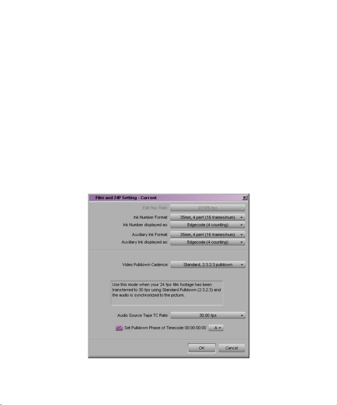
Chapter 3 Preparing to Capture
• NTSC Has Setup: This option applies to standard NTSC format and is
selected by default. If the source footage is in the NTSC-EIAJ format
standard (used primarily in Japan), deselect NTSC Has Setup.
For more information about General settings, see “General Settings” in the
Help.
c
The Avid editing system will not prevent you from using non-Avid
drives, but their reliability cannot be guaranteed.
Transfer Settings for Film Projects
The following settings are important for transferring media in a film
project. You should set the transfer settings for film projects immediately
after you create a new project and before capturing. For information about
other film settings, see “Film and 24p Settings” in the Help.
78
Page 79

Selecting Settings
For information about
film-to-tape transfer
methods, see
Film-to-Tape Transfers
in the Help.
• Video Pulldown Cadence: allows you to specify the type of
film-to-tape transfer that you capture:
- Video rate, no pulldown: Select this option when working with
24-fps footage that has been transferred MOS (roughly translated
as “without sound”) to 30 fps by speeding up the film, and the
audio has been brought into the Avid system separately at 100
percent of the actual speed.
- Standard 2:3:2:3 pulldown: Select this option when working with
24-fps footage that has been transferred to 30 fps by duplicating
frames (pulldown) and the audio has been synchronized to the
picture.
- Advanced 2:3:3:2 pulldown: Select this option when using native
DV editing with capture over Firewire.
If you are capturing sound that has been created during an NTSC
film-to-tape transfer, you need to set the pulldown switch before you
begin capturing. See “Setting the Pulldown Switch” on page 101.
For NTSC projects, you can mix footage transferred with pulldown
and footage transferred without pulldown (video rate). You can also
mix sound transferred at 0.99 (with pulldown) and 1.00 (without
pulldown).
• (PAL only) You define the Audio Transfer Rate in the New Project
dialog box when you create a 24p PAL film project. (It is not needed
for a 25p PAL project because there is no film speedup during the
transfer.) It is important to keep the audio transfer rate constant for the
project. However, if there is a specific element that you need to capture
at a different rate, you can use the Film and 24p Settings dialog box to
change the rate. The following options are available:
- Film Rate (100%): Select this option when your 24-fps film
footage has been transferred MOS to 25 fps by speeding up the
film, and the audio comes in separately at 100 percent of the actual
speed (PAL Method 2).
- Video Rate (100%+): Select this option when your 24-fps film
footage has been transferred to 25 fps by speeding up the film, and
the audio is synchronized to the video picture. This means that the
audio speed is increased by 4.1 percent (PAL Method 1).
79
Page 80

Chapter 3 Preparing to Capture
For PAL 24p projects, you can mix audio that has been transferred at
4.1 percent speedup (video rate, PAL Method 1) with audio that has
not been transferred (film rate, PAL Method 2). However, Avid does
not recommend this.
n
The Info tab in the Project window allows you to view the audio transfer
rate you selected when you created the project. The actual audio transfer
rate might be different from the display if you used the Film and 24p
Settings dialog box to change the audio transfer rate.
• Audio Source Tape TC Rate allows you to specify the digital
audiotape (DAT) timecode format: either 30 fps or 29.97 fps (NTSC
only). This timecode format must conform to the timecode format on
your original DAT tapes. This setting is active when capturing audio
only.
This setting does not appear in 23.976p projects.
• Set Pulldown-to-Timecode Relationship allows you to set a default
pulldown phase for a 24p NTSC project. See “Setting the Pulldown
Switch” on page 101.
Selecting Capture Settings
Capture settings include essential options for capturing, batch capturing,
autocapturing, capturing to multiple media files, and DV scene extraction.
To open the Capture Settings dialog box:
80
t Double-click Capture in the Settings scroll list.
For more information on Capture Settings tabs, see “Capture Settings” in
the Help:
• Capture settings General tab
• Capture settings Batch tab
• Capture settings Edit tab
• Capture settings Media Files tab
• Capture settings DV Options tab
Page 81

Creating a GPI Trigger
You can define and save custom general-purpose interface (GPI) settings.
After you create a GPI setting, you can use it repeatedly. For example, you
can create two GPIs: one to start capturing and one to stop capturing.
Selecting Settings
n
n
To access the GPI Settings dialog box, you must have a V-LAN VLXi (GPI)
connected to your system.
V-LAN VLXi is not compatible with the V-LAN Express single-device
controller. For device connectivity information, refer to your V-LAN
documentation.
To create a GPI trigger:
1. Double-click Deck Configuration in the Setting scroll list.
The Deck Configuration dialog box appears.
2. Click Add Channel.
A Channel dialog box appears.
3. Click the Channel Type pop-up menu, and select VLAN VLX.
4. Click the Port pop-up menu, and select COM1 or COM2.
5. Click OK.
A dialog box appears, asking if you want to automatically configure
the channel now.
6. Click Yes.
The connected GPI is automatically detected and appears in the Deck
Configuration dialog box.
7. Double-click the VLAN VLXi-GT device name in the Deck
Configuration dialog box.
The GPI Settings dialog box appears.
8. Select the appropriate settings. For a description of GPI settings
options, see Table 4 on page 82.
81
Page 82

Chapter 3 Preparing to Capture
9. Click Add.
The GPI Node Settings dialog box appears. For a description of GPI
node settings options, see Table 5 on page 83.
10. Select the appropriate settings.
11. Click OK.
The GPI Settings dialog box appears.
12. Click OK to set the GPI.
13. Click Apply in the Deck Configuration dialog box.
Table 4 GPI Settings Options
Option Description
Name The V-LAN VLXi name appears. Keep the default or type a new name.
Description (Option) Add a description of the GPI trigger.
Device Type Select V-LAN, the Avid-supported device type.
Address Valid addresses on the V-LAN network are 16 through 19. This address must
match the internal V-LAN address.
Pulse Duration Pulse durations are expressed in milliseconds.
GPI Control Enable When you deselect this option, you disable the GPI but keep the GPI settings.
This is useful for troubleshooting purposes.
Edit Click to edit an existing GPI node.
Delete Click to delete an existing GPI node.
Add Click to add another GPI node.
82
Page 83

Selecting Settings
Table 5 GPI Node Settings Options
Option Description
Function Select a function for a particular node:
• Capture in (Satellite mode)
•Play in
• Cue to first frame
• Stop in
• Capture out (Satellite mode)
• Play out
• Stop out
Node Click the Node pop-up menu, and select a Node. The options are node 1 through 6. These
correspond to the physical connectors on the back of the V-LAN VLXi box.
Action Select an action:
• Set activates a command.
• Reset deactivates a command.
• Pulse switches the state for the amount of time set in Pulse Duration in the GPI Settings
dialog box.
Deleting a GPI Setting
You can delete a GPI setting that you have defined so that it no longer
appears as an option in your GPI Settings dialog box.
To delete a GPI setting:
1. Double-click Deck Configuration in the Setting scroll list.
The Deck Configuration dialog box appears.
2. Click the VLXi-GT text box.
3. Select the name of the GPI you want to delete.
4. Click Delete.
83
Page 84

Chapter 3 Preparing to Capture
5. Click OK.
6. Click Apply.
The GPI setting is deleted.
Editing an Existing GPI Setting
To edit a GPI setting:
1. Double-click Deck Configuration in the Setting scroll list.
The Deck Configuration dialog box appears.
2. Click the VLXi-GT text box.
3. Select the name of the existing GPI you want to edit.
4. Click Edit.
5. Make the applicable changes.
6. Click OK.
7. Click Apply.
The GPI setting is updated.
Configuring Decks
Deck Configuration settings allow you to establish deck control parameters
for a single deck or for multiple decks. As with all settings, you can create
multiple versions, allowing you to select among them for frequent changes
in hardware configurations.
Deck Configuration settings and global Deck Preferences settings appear
as separate items in the Settings scroll list of the Project window.
84
Page 85

Deck control settings
Configuring Decks
n
You must manually configure the appropriate hardware connections before
Deck Configuration settings can take effect. For more information, see the
Using the Avid Adrenaline DNA Installation Instructions for the Windows
XP Operating System or Using the Avid Mojo DNA Installation
Instructions for the Windows XP Operating System.
For more information about Deck Configuration settings, see “Deck
Configuration Settings” in the Help.
85
Page 86
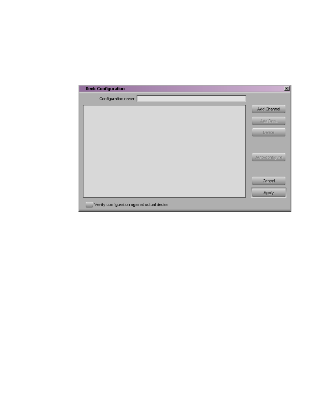
Chapter 3 Preparing to Capture
To configure a deck or multiple decks:
1. Double-click Deck Configuration in the Settings scroll list.
The Deck Configuration dialog box opens.
86
2. If you are configuring your system for the first time, click Add
Channel to add a new channel box on the left side of the Deck
Configuration dialog box and automatically open the Channel dialog
box.
3. Depending on your system configuration, click the Channel Type
pop-up menu, and select one of the following items:
- Direct, if you are connecting a deck directly to the serial port
- FireWire, if you are connecting a deck by means of a FireWire
connection
- VLAN VLX, if you are controlling decks through a V-LAN/VLXi
connection
4. Click the Port pop-up menu, and select the port to which you are
connecting the deck.
Page 87

Configuring Decks
n
If you are not sure which port to select, check the 9-pin serial port
connectors on the back of the system. If the ports are not labeled, see the
hardware documentation supplied with your system.
5. Click OK to close the Channel dialog box.
A dialog box opens asking if you want to automatically configure the
channel now.
6. Click Yes if you want to automatically configure the channel.
A new channel appears in the display area of the Deck Configuration
dialog box, along with the autoconfigured deck.
Channels appear on the left side.
Decks appear on the right side.
n
You can reopen the Channel settings to change the options at any time by
double-clicking the channel box.
7. If you did not autoconfigure the deck, click the channel box to select it.
8. Click Add Deck to open the Deck Settings dialog box.
87
Page 88

Chapter 3 Preparing to Capture
n
n
With a deck already connected to the system, you can click Auto-configure
to bypass the Deck Settings dialog box and automatically configure a deck
with the default settings.
Not all DV devices respond to the Auto-configure command. Due to this
limitation, Auto-configure will select only the generic devices. When a
digital camera is attached to your system, click the Device pop-up menu,
and select the proper device. When a deck with a transcoder is attached,
click the Device pop-up menu, and select the applicable transcoder.
88
n
9. Select settings based on your device. For information on Deck settings,
see “Deck Settings Options” on page 89.
10. Click OK to close the Deck Settings dialog box and to return to the
Deck Configuration dialog box.
You can reopen the Deck Settings dialog box to change the options at any
time by double-clicking the deck box in the Deck Configuration dialog box.
Page 89

Configuring Decks
11. Repeat steps 1 through 10 for each additional channel or deck you
want to configure.
12. (Option) Select “Verify configuration against actual decks” if you want
the system to check the deck configuration against the devices
physically connected to the system.
The system checks the deck configuration after you click Apply in the
Deck Configuration dialog box and when you start the Avid editing
application. A message warns you if the configuration does not match
the deck.
13. Type a name in the Configuration Name text box to name the deck
configuration. The new deck configuration will appear in the Settings
scroll list.
14. Click Apply to complete the configurations and close the Deck
Configuration dialog box.
15. If necessary, double-click Deck Preferences in the Settings scroll list to
adjust global deck preferences.
For more information about Deck Preferences, see “Deck Preferences
Settings” in the Help.
Deck Settings Options
To open the Deck Settings dialog box, do one of the following:
t Click Add Deck in the Deck Configuration dialog box.
t In the Deck Controls area of the Capture tool, click the Deck Selection
pop-up menu and select Adjust Deck.
89
Page 90

Chapter 3 Preparing to Capture
t Double-click the deck box in the Deck Configuration dialog box.
The Deck Settings dialog box opens.
Notes field
Model pop-up
menu
Manufacturer
pop-up menu
Table 6 describes the Deck Settings options.
Table 6 Deck Settings Options
Option Suboption Description
Name — Type your custom name for the tape deck. The default name matches the
deck type.
Description — Enter notes about the deck.
Notes — Displays configuration information, supplied by Avid, about the deck
you have selected. Not all decks include this information.
90
Page 91

Configuring Decks
Table 6 Deck Settings Options (Continued)
Option Suboption Description
Device — Select your model and manufacturer from the pop-up menus. If your DV
device (deck, camera, or transcoder) does not appear in the list, click the
Manufacturer pop-up menu, select Generic, and then click the Model
pop-up menu, and select one of the following:
t DVBasicDevice-NTSC
t DVDevice-NTSC
t DVTranscoder-NTSC
t Edit-Deck-NTSC
t Play-Deck-NTSC
t Capture-Deck-NTSC
Address — For VLXi use only (see your VLXi documentation). If you are using
direct serial port deck control, this option is unavailable.
Preroll — Specifies how many seconds the tape rolls before a record or digital cut
starts. The default is based on the type of videotape recorder (VTR).
Fast Cue — Speeds up long searches if your decks can read timecode in fast forward
or rewind mode. Otherwise, this option is not useful.
Switch to ff/rew
(seconds): n
Select this option if you want the Avid editing application to switch to
fast forward or rewind if the target timecode is beyond the specified
number of seconds from your current location on the tape.
By default, the deck switches to fast forward or rewind to reach a target
timecode that is more than 60 seconds away.
If your deck shuttles very quickly, you can increase this number so the
system uses fast cue only for long searches.
Switch to search
(seconds): n
Select this option if you want the Avid editing application to switch out
of fast forward or rewind when it is within the specified number of
seconds of the target timecode. By default, the system switches to search
mode when it is 60 seconds from the target timecode.
91
Page 92
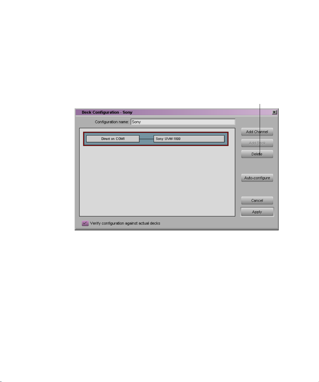
Chapter 3 Preparing to Capture
Deleting Deck Configurations
To delete a deck configuration:
1. Double-click Deck Configuration in the Settings scroll list.
The Deck Configuration dialog box opens.
Delete button
2. Click the names of the currently configured channel and deck in the
display area. The entire display area should have a red border.
3. Click Delete.
4. Click Apply to complete the changes and close the dialog box.
Setting Deck Preferences
Deck preferences are global settings for basic deck control. These settings
apply to all decks connected to your system, regardless of your deck
configuration. You can open the Deck Preferences dialog box from the
Settings scroll list.
92
Page 93
Understanding Drop-Frame and Non-Drop-Frame Timecodes
For more information about Deck Preferences, see “Deck Preferences
Settings” in the Help.
Understanding Drop-Frame and Non-Drop-Frame
Timecodes
Timecode is an electronic indexing method that denotes hours, minutes,
seconds, and frames that have elapsed on a videotape. For example, a
timecode of 01:03:30:10 denotes a frame that is marked at 1 hour,
3 minutes, 30 seconds, and 10 frames.
NTSC video (the video format used mainly in the United States) uses one
of two formats: drop-frame timecode and non-drop-frame timecode.
Drop-frame (DF) timecode is designed to match the NTSC scan rate of
29.97 frames per second (fps). Two frames of timecode are dropped every
93
Page 94

Chapter 3 Preparing to Capture
minute except for the tenth minute. No video frames are actually dropped.
Drop-frame timecode is indicated by semicolons between the digits; for
example, 01;00;00;00.
Non-drop-frame (NDF) timecode tracks NTSC video at a rate of 30 fps
and is indicated by colons between the digits; for example, 01:00:00:00.
Non-drop-frame timecode can be easier to work with, but does not provide
accurate timing for NTSC broadcast.
For example, a typical 1-hour show uses 52 minutes of video. If your
program ends at 01:52:00:00 (non-drop-frame), and it is broadcast at 29.97
fps, it will last 94 frames too long (approximately 3 seconds). The final
credits could be cut off.
PAL video (the video format used in many countries other than the United
States) uses a scan rate of 25 fps. Timecode is indicated by colons. There is
no need for drop-frame timecode in PAL video.
You set the default timecode format for logging clips in the Deck
Preferences dialog box (see “Setting Deck Preferences” on page 92). You
set the default starting timecode in the General Settings dialog box (see
“General Settings” in the Help). In both cases, you can select drop or
non-drop.
You can change the starting timecode of a sequence or, for NTSC projects,
the type of timecode. See “Changing the Sequence Info” in the Help.
Setting Up the Capture Tool
The Capture tool provides controls for cueing, marking, and logging
footage, and specifies capturing parameters such as source and target
locations.
94
Page 95
Opening the Capture Tool
To open the Capture tool:
t Select Tools > Capture.
The Capture tool opens.
Setting Up the Capture Tool
Deck Selection
pop-up menu
Setting the Video and Audio Input
The Video and Audio pop-up menus show you the current input settings
for the Video Input tool and the Input tab in the Audio Project Settings
dialog box. The pop-up menus also provide a convenient way to change the
settings if necessary. The choices are as follows:
• Video input: Composite, Component, S-video, SDI, and DV
Software-only models include: OHCI
95
Page 96

Chapter 3 Preparing to Capture
• Audio input: XLR (+4dBu), RCA (–10dBu), AES/EBU,
Optical (ADAT), and Optical (S/PDIF)
Software-only models include: Aux, Video, CD Player, Line In,
Microphone, Phone Line, and OHCI
For more information, see “Preparing for Audio Input” on page 113.
n
Selecting Video Input
Selecting Audio Input
If you change the settings, the settings in the Video Input tool or in the
Audio Project Settings dialog box change automatically.
To select video input:
t The following video input is already selected:
To select audio input:
t Click the Audio pop-up menu, and select one of the following:
- Composite
- Component
-S-Video
-SDI
-DV
- OHCI (software-only models)
-XLR (+4dBu)
96
- RCA (–10dBu)
-AES/EBU
-Optical(ADAT)
- Optical (S/PDIF)
- OHCI (software-only models)
- CD Player (software-only models)
- Line In (software-only models)
Page 97

Selecting a Deck
Setting Up the Capture Tool
- Microphone (software-only models)
- Phone Line (software-only models)
The Deck Selection pop-up menu in the Capture tool contains a list of
decks or cameras that were connected to the system, powered up, and
initialized when you entered Capture mode. The first deck or camera in the
list is selected by default, unless all decks or cameras are offline.
The Deck Selection pop-up menu also lists three commands:
• Adjust Deck opens the Deck Settings dialog box. Changes you make
apply to the selected deck. For information on Deck settings, see
“Deck Settings Options” on page 89.
• Auto-configure allows you to automatically configure the selected
deck with the default deck settings for that deck.
• Check Decks helps to reestablish deck control if the power to your
decks was turned off or the decks were disconnected when you first
entered Capture mode.
n
You must have V-LAN
VLXi hardware to
manage more than one
deck at a time. For
more information on
V-LAN equipment,
contact your Avid sales
representative.
If the words “No Deck” appear in the pop-up menu, you need to configure
a deck in the Deck Configuration dialog box. See “Configuring Decks” on
page 84.
If a deck name appears in italics in the pop-up menu, the deck has lost
power or has been disconnected. To reestablish deck control, click the
pop-up menu, and select Check Decks.
Once deck control has been properly initialized, it will remain active for all
deck controllers throughout the session until you quit the application.
To activate playback from an available deck or camera, do one of the
following:
t Select the name of a previously configured deck or camera.
t Select Auto-configure to automatically establish the default deck
settings for a VTR that is currently connected to the system.
97
Page 98

Chapter 3 Preparing to Capture
n
Selecting a Tape
Not all DV devices respond to the Auto-configure command. Due to this
limitation, Auto-configure selects only the generic devices. When a digital
camera is attached to your software-only system, click the Deck Selection
pop-up menu, and select the proper device. When a deck with a transcoder
is attached, click the Deck Selection pop-up menu, and select the
applicable deck.
If you forgot to turn on or connect a deck or camera prior to entering
Capture mode:
1. Make sure the deck is connected and the power is turned on.
2. Select Check Decks to reestablish deck control.
To select a source tape:
1. Insert a tape into your deck.
The Select Tape dialog box opens.
98
Page 99

Setting Up the Capture Tool
2. In an NTSC project, play the tape briefly so the system can detect the
timecode format of the tape (drop-frame or non-drop-frame).
Otherwise, the system maintains the timecode format set in the Deck
Preferences dialog box, regardless of the format on the tape, and you
might receive a message indicating a wrong tape.
n
For information on tape
naming conventions,
see “Naming Tapes” on
page 35.
Drop-frame timecode appears in the Timecode indicator with semicolons
between hours, minutes, seconds, and frames. Non-drop-frame timecode
appears with colons. (Drop-frame timecode and non-drop-frame timecode
exist only in NTSC projects.)
3. Provide the system with a tape name in one of the following ways:
t Select the name of the tape from the list displayed in the Select
Tape dialog box, and click OK.
t Click New if the tape is not in the list. Type the new name in the
dialog box, and click OK.
Selecting Source Tracks
You can select the tracks to capture from the source tape.
To select only those tracks that you want to capture:
t Click the Channel Selection buttons in the Capture tool.
The TC (timecode) track is selected by default.
99
Page 100

Chapter 3 Preparing to Capture
Channel
Selection
buttons
n
If you are not seeing the source video or hearing source audio in Capture
mode, click the Channel Selection buttons to make sure the correct tracks
have been selected.
To select or deselect all tracks at once:
t Press and hold the Alt key, and click any Channel Selection button.
Setting the Video and Audio Input
The Video and Audio pop-up menus show you the current input settings
for the Video Input tool and the Input tab in the Audio Project Settings
dialog box. The pop-up menus also provide a convenient way to change the
settings if necessary. The choices are as follows:
• Video input: Composite, S-video, Component, SDI, DV
• Audio input: XLR (+4dBu), RCA (-10dBu), DV, AES/EBU,
S/PDIF, Optical (ADAT), Optical (S/PDIF)
100
 Loading...