

Page 1

Avid® NewsCutter® and
NewsCutter XP
Site Preparation Guide
Page 2

Copyright and Disclaimer
Product specifications are subject to change without notice and do not represent a commitment on
the part of Avid Technology, Inc. The software described in this document is furnished under a
license agreement. You can obtain a copy of that license by visiting Avid's Web site at
www.avid.com. The terms of that license are also available in the product in the same directory as
the software. The software may not be reverse assembled and may be used or copied only in
accordance with the terms of the license agreement. It is against the law to copy the software on any
medium except as specifically allowed in the license agreement. Avid products or portions thereof
are protected by one or more of the following United States patents: 4,746,994; 4,970,663;
5,045,940; 5,063,448; 5,077,604; 5,245,432; 5,267,351; 5,309,528; 5,325,200; 5,355,450;
5,396,594; 5,440,348; 5,452,378; 5,467,288; 5,513,375; 5,528,310; 5,557,423; 5,568,275;
5,577,190; 5,583,496; 5,584,006; 5,627,765; 5,634,020; 5,640,601; 5,644,364; 5,654,737;
5,701,404; 5,715,018; 5,719,570; 5,724,605; 5,726,717; 5,729,673; 5,731,819; 5,745,637;
5,752,029; 5,754,180; 5,754,851; 5,781,188; 5,799,150; 5,812,216; 5,828,678; 5,842,014;
5,852,435; 5,883,670; 5,889,532; 5,892,507; 5,905,841; 5,912,675; 5,929,836; 5,929,942;
5,930,445; 5,930,797; 5,946,445; 5,966,134; 5,977,982; 5,986,584; 5,987,501; 5,995,079;
5,995,115; 5,999,190; 5,999,406; 6,009,507; 6,011,562; 6,014,150; 6,016,152; 6,016,380;
6,018,337; 6,023,531; 6,023,703; 6,031,529; 6,035,367; 6,038,573; 6,052,508; 6,058,236;
6,061,758; 6,072,796; 6,084,569; 6,091,422; 6,091,778; 6,105,083; 6,118,444; 6,128,001;
6,128,681; 6,130,676; 6,134,379; 6,134,607; 6,137,919; 6,141,007; 6,141,691; 6,154,221;
6,157,929; 6,160,548; 6,161,115; 6,167,404; 6,174,206; 6,192,388; 6,198,477; 6,208,357;
6,211,869; 6,212,197; 6,215,485; 6,223,211; 6,226,005; 6,226,038; 6,229,576; 6,239,815;
6,249,280; 6,269,195; 6,271,829; 6,301,105; 6,310,621; 6,314,403; 6,317,142; 6,317,153;
6,317,515; D352,278; D372,478; D373,778; D392,267; D392,268; D392,269; D395,291;
D396,853; D398,912. Additional U.S. and foreign patents pending. No part of this document may
be reproduced or transmitted in any form or by any means, electronic or mechanical, including
photocopying and recording, for any purpose without the express written permission of Avid
Technology, Inc.
Copyright © 2002 Avid Technology, Inc. and its licensors. All rights reserved. Printed in USA.
The following disclaimer is required by Sam Leffler and Silicon Graphics, Inc. for the
use of their TIFF library:
Copyright © 1988–1997 Sam Leffler
Copyright © 1991–1997 Silicon Graphics, Inc.
Permission to use, copy, modify, distribute, and sell this software [i.e., the TIFF library] and its
documentation for any purpose is hereby granted without fee, provided that (i) the above copyright
notices and this permission notice appear in all copies of the software and related documentation,
and (ii) the names of Sam Leffler and Silicon Graphics may not be used in any advertising or
publicity relating to the software without the specific, prior written permission of Sam Leffler and
Silicon Graphics.
THE SOFTWARE IS PROVIDED “AS-IS” AND WITHOUT WARRANTY OF ANY KIND, EXPRESS,
IMPLIED OR OTHERWISE, INCLUDING WITHOUT LIMITATION, ANY WARRANTY OF
MERCHANTABILITY OR FITNESS FOR A PARTICULAR PURPOSE.
IN NO EVENT SHALL SAM LEFFLER OR SILICON GRAPHICS BE LIABLE FOR ANY SPECIAL,
INCIDENTAL, INDIRECT OR CONSEQUENTIAL DAMAGES OF ANY KIND, OR ANY DAMAGES
WHATSOEVER RESULTING FROM LOSS OF USE, DATA OR PROFITS, WHETHER OR NOT
ADVISED OF THE POSSIBILITY OF DAMAGE, AND ON ANY THEORY OF LIABILITY, ARISING OUT
OF OR IN CONNECTION WITH THE USE OR PERFORMANCE OF THIS SOFTWARE.
The following disclaimer is required by the Independent JPEG Group:
Portions of this software are based on work of the Independent JPEG Group.
The following disclaimer is required by Paradigm Matrix:
Portions of this software licensed from Paradigm Matrix.
Page 3

The following disclaimer is required by Ray Sauers Associates, Inc.:
“Install-It” is licensed from Ray Sauers Associates, Inc. End-User is prohibited from taking any
action to derive a source code equivalent of “Install-It,” including by reverse assembly or reverse
compilation, Ray Sauers Associates, Inc. shall in no event be liable for any damages resulting from
reseller’s failure to perform reseller’s obligation; or any damages arising from use or operation of
reseller’s products or the software; or any other damages, including but not limited to, incidental,
direct, indirect, special or consequential Damages including lost profits, or damages resulting from
loss of use or inability to use reseller’s products or the software for any reason including copyright or
patent infringement, or lost data, even if Ray Sauers Associates has been advised, knew or should
have known of the possibility of such damages.
The following disclaimer is required by Videomedia, Inc.:
“Videomedia, Inc. makes no warranties whatsoever, either express or implied, regarding this
product, including warranties with respect to its merchantability or its fitness for any particular
purpose.”
“This software contains V-LAN ver. 3.0 Command Protocols which communicate with V-LAN ver. 3.0
products developed by Videomedia, Inc. and V-LAN ver. 3.0 compatible products developed by
third parties under license from Videomedia, Inc. Use of this software will allow “frame accurate”
editing control of applicable videotape recorder decks, videodisc recorders/players and the like.”
The following notice is required by Altura Software, Inc. for the use of its Mac2Win
software and Sample Source Code:
©1993–1998 Altura Software, Inc.
The following notice is required by Ultimatte Corporation:
Certain real-time compositing capabilities are provided under a license of such technology from
Ultimatte Corporation and are subject to copyright protection.
Attn. Government User(s). Restricted Rights Legend
U.S. GOVERNMENT RESTRICTED RIGHTS. This Software and its documentation are “commercial
computer software” or “commercial computer software documentation.” In the event that such
Software or documentation is acquired by or on behalf of a unit or agency of the U.S. Government,
all rights with respect to this Software and documentation are subject to the terms of the License
Agreement, pursuant to FAR §12.212(a) and/or DFARS §227.7202-1(a), as applicable.
Trademarks
AirPlay, AudioVision, Avid, Avid Xpress, CamCutter, Digidesign, FieldPak, Film Composer, HIIP,
Image Independence, Marquee, Media Composer, Media Recorder, NewsCutter, OMF,
OMF Interchange, Open Media Framework, Pro Tools, and Softimage are registered trademarks and
888 I/O, AirSPACE, AirSPACE HD, AniMatte, AudioSuite, AutoSync, AVIDdrive, AVIDdrive Towers,
AvidNet, Avid Production Network, AvidProNet, AvidProNet.com, AVIDstripe, Avid Unity,
AVX, DAE, D-Fi, D-fx, Digidesign Audio Engine, DINR, D-Verb, ExpertRender, FilmScribe,
HyperSPACE, HyperSPACE HDCAM, Intraframe, iS9, iS18, iS23, iS36, Lo-Fi, Magic Mask,
make manage move | media, Matador, Maxim, MCXpress, MEDIArray, MediaDock,
MediaDock Shuttle, Media Fusion, Media Illusion, MediaLog, Media Reader, MediaShare, Meridien,
NaturalMatch, NetReview, OMM, Open Media Management, ProEncode, QuietDrive, R&A, Recti-Fi,
Review & Approval, rS9, rS18, Sci-Fi, Sound Designer II, SPACE, SPACEShift, Symphony, Trilligent,
UnityRAID, Vari-Fi, Video Slave Driver, and VideoSPACE are trademarks of Avid Technology, Inc.
iNEWS and Media Browse are trademarks of iNews, LLC.
Page 4

Adobe, Acrobat, and Reader are registered trademarks of Adobe Systems Incorporated in the
United States and/or other countries. Compaq is a registered trademark of Compaq Computer
Corporation. IBM and IntelliStation are registered trademarks of International Business Machines
Corporation. RCA is a registered trademark of General Electric Company. Texas Instruments is a
registered trademark of Texas Instruments. Videomedia, V-LAN, and VLXi are registered trademarks
of Videomedia, Inc. Vixel is a registered trademark of Vixel Corporation. Windows is a registered
trademark of Microsoft Corporation in the United States and/or other countries. All other trademarks
contained herein are the property of their respective owners.
Avid NewsCutter and NewsCutter XP Site Preparation Guide • Part 0130-05052-01
Rev. A • April 2002
Page 5

Contents
Using This Guide
Who Should Use This Guide . . . . . . . . . . . . . . . . . . . . . . . . . . . . . . . . . . . 9
About This Guide . . . . . . . . . . . . . . . . . . . . . . . . . . . . . . . . . . . . . . . . . . . 10
Symbols and Conventions . . . . . . . . . . . . . . . . . . . . . . . . . . . . . . . . . . . . 10
If You Need Help . . . . . . . . . . . . . . . . . . . . . . . . . . . . . . . . . . . . . . . . . . . . 11
Related Information. . . . . . . . . . . . . . . . . . . . . . . . . . . . . . . . . . . . . . . . . . 11
If You Have Documentation Comments . . . . . . . . . . . . . . . . . . . . . . . . 14
How to Order Documentation. . . . . . . . . . . . . . . . . . . . . . . . . . . . . . . . . 14
Avid NewsCutter Site Preparation
Avid System Layouts . . . . . . . . . . . . . . . . . . . . . . . . . . . . . . . . . . . . . . . . 16
NewsCutter Layout . . . . . . . . . . . . . . . . . . . . . . . . . . . . . . . . . . . . . . 16
Avid Unity for News Workgroup Layout . . . . . . . . . . . . . . . . . . . 18
Fibre Channel Workgroup Configuration . . . . . . . . . . . . . . . . . . . 20
NewsCutter Connectors . . . . . . . . . . . . . . . . . . . . . . . . . . . . . . . . . . 20
Input and Output Connections . . . . . . . . . . . . . . . . . . . . . . . . . . . . 22
Avid Meridien I/O Box Connectors. . . . . . . . . . . . . . . . . . . . . 23
1394 Board Connectors. . . . . . . . . . . . . . . . . . . . . . . . . . . . . . . . 28
Cabling Guidelines. . . . . . . . . . . . . . . . . . . . . . . . . . . . . . . . . . . . . . . 28
Component Dimensions and Weights . . . . . . . . . . . . . . . . . . . . . . . . . . 31
Site Requirements . . . . . . . . . . . . . . . . . . . . . . . . . . . . . . . . . . . . . . . . . . . 33
Power Requirements . . . . . . . . . . . . . . . . . . . . . . . . . . . . . . . . . . . . . 33
Source Requirements . . . . . . . . . . . . . . . . . . . . . . . . . . . . . . . . . . . . . 35
Synchronization Requirements . . . . . . . . . . . . . . . . . . . . . . . . . . . . 35
Printing Requirements . . . . . . . . . . . . . . . . . . . . . . . . . . . . . . . . . . . 35
Page 6

6
Telephone Requirements . . . . . . . . . . . . . . . . . . . . . . . . . . . . . . . . . 36
Environmental Requirements . . . . . . . . . . . . . . . . . . . . . . . . . . . . . 36
Networking Requirements. . . . . . . . . . . . . . . . . . . . . . . . . . . . . . . . 37
Fiber-Optic Switch . . . . . . . . . . . . . . . . . . . . . . . . . . . . . . . . . . . 37
Ethernet Hub. . . . . . . . . . . . . . . . . . . . . . . . . . . . . . . . . . . . . . . . 37
Patch Panel . . . . . . . . . . . . . . . . . . . . . . . . . . . . . . . . . . . . . . . . . 38
Pin Assignments . . . . . . . . . . . . . . . . . . . . . . . . . . . . . . . . . . . . . . . . . . . . 38
Serial Ports . . . . . . . . . . . . . . . . . . . . . . . . . . . . . . . . . . . . . . . . . . . . . 38
VGA Monitor Port . . . . . . . . . . . . . . . . . . . . . . . . . . . . . . . . . . . . . . . 40
Keyboard and Mouse Connectors. . . . . . . . . . . . . . . . . . . . . . . . . . 41
RJ-45 Jacks. . . . . . . . . . . . . . . . . . . . . . . . . . . . . . . . . . . . . . . . . . . . . . 42
1394 Connector (NewsCutter XP Only) . . . . . . . . . . . . . . . . . . . . . 44
GPI Connector . . . . . . . . . . . . . . . . . . . . . . . . . . . . . . . . . . . . . . . . . . 45
SDTI Connectors (NewsCutter Only Option) . . . . . . . . . . . . . . . . 45
Regulatory and Safety Notices
FCC Notice. . . . . . . . . . . . . . . . . . . . . . . . . . . . . . . . . . . . . . . . . . . . . . . . . 47
Canadian ICES-003 . . . . . . . . . . . . . . . . . . . . . . . . . . . . . . . . . . . . . . . . . . 48
European Union Notice . . . . . . . . . . . . . . . . . . . . . . . . . . . . . . . . . . . . . . 48
Australia and New Zealand EMC Regulations . . . . . . . . . . . . . . . . . . 50
Taiwan EMC Regulations . . . . . . . . . . . . . . . . . . . . . . . . . . . . . . . . . . . . 50
Index
Page 7

Figures
Figure 1 Sample NewsCutter System Layout . . . . . . . . . . . . . . . 17
Figure 2 Sample Layout for an Avid Unity for News
Workgroup Environment . . . . . . . . . . . . . . . . . . . . . . 19
Figure 3 Meridien I/O Box Audio Connectors . . . . . . . . . . . . . . 23
Figure 4 Meridien I/O Box Video Connectors . . . . . . . . . . . . . . 25
Figure 5 Meridien I/O Box Serial Digital Connectors . . . . . . . . 27
Figure 6 1394 Board DV Connectors . . . . . . . . . . . . . . . . . . . . . . . 28
Figure 7 9-Pin Serial Connector . . . . . . . . . . . . . . . . . . . . . . . . . . . 39
Figure 8 15-Pin VGA Monitor Connector. . . . . . . . . . . . . . . . . . . 40
Figure 9 6-Pin PS/2 Connector . . . . . . . . . . . . . . . . . . . . . . . . . . . 41
Figure 10 8-Pin Category 5 RJ-45 Connector . . . . . . . . . . . . . . . . . 43
Figure 11 6-Pin 1394 Connector . . . . . . . . . . . . . . . . . . . . . . . . . . . . 44
Figure 12 GPI Node Terminals. . . . . . . . . . . . . . . . . . . . . . . . . . . . . 45
7
Figure 13 BNC Connectors on the Breakout Box. . . . . . . . . . . . . . 45
Figure 14 BNC Connectors on the MPEG SDTI-CP
Adapter Board. . . . . . . . . . . . . . . . . . . . . . . . . . . . . . . . 46
Page 8

8
Tables
Table 1 NewsCutter Connector Identifiers . . . . . . . . . . . . . . . . .21
Table 2 Meridien I/O Box Audio Identifiers. . . . . . . . . . . . . . . .24
Table 3 Meridien I/O Box Video Identifiers . . . . . . . . . . . . . . . .25
Table 4 Meridien I/O Box Serial Digital Identifiers. . . . . . . . . .27
Table 5 System Cable Lengths . . . . . . . . . . . . . . . . . . . . . . . . . . .29
Table 6 Physical Specifications for Components . . . . . . . . . . . .31
Table 7 Power Requirements . . . . . . . . . . . . . . . . . . . . . . . . . . . . .34
Table 8 Environmental Specifications . . . . . . . . . . . . . . . . . . . . .36
Table 9 Serial Connector Pin Assignments . . . . . . . . . . . . . . . . .39
Table 10 VGA Monitor Connector Pin Assignments . . . . . . . . . .40
Table 11 PS/2 Connector Pin Assignments. . . . . . . . . . . . . . . . . .42
Table 12 Category 5 RJ-45 Connector Pin Assignments . . . . . . .43
Table 13 6-Pin 1394 Connector Pin Assignments . . . . . . . . . . . . .44
Page 9

Using This Guide
This guide provides site requirement information for the Avid
NewsCutter® and NewsCutter XP systems. Unless noted otherwise,
“NewsCutter” refers to both NewsCutter and NewsCutter XP
throughout this guide.
n
The documentation describes the features and hardware of all models.
Therefore, your system might not contain certain features and hardware that
are covered in the documentation.
Who Should Use This Guide
This guide is intended for all NewsCutter users, from beginning to
advanced. Read this guide if you are responsible for preparing a site
for installation.
®
Page 10

10
About This Guide
This guide provides specifications for your NewsCutter system
components in the following areas:
• Connectors
•Cabling
• Physical (dimensions and weights)
•Power
• Environmental
Symbols and Conventions
n
c
Unless noted otherwise, the material in this document applies to the
Windows
The NewsCutter documentation uses the following special symbols
and conventions:
1. Numbered lists, when the order of the items is important.
• Bulleted lists, when the order of the items is unimportant.
A note provides important related information, reminders, recommendations,
and strong suggestions.
A caution means that a specific action you take could cause harm to
your computer or cause you to lose data.
®
2000 operating system.
a. Alphabetical lists, when the order of secondary items is
important.
- Indented dashed lists, when the order of secondary items is
unimportant.
Using This Guide
Page 11

11
w
A warning describes an action that could cause you physical harm.
Follow the guidelines in this guide or on the unit itself when
handling electrical equipment.
If You Need Help
If you are having trouble using the NewsCutter system, you should:
1. Retry the action, carefully following the instructions given for that
task in this guide.
2. Check the documentation that came with your hardware for
maintenance or hardware-related issues.
3. Check the release notes supplied with your Avid application for
information on accessing the Avid Web site and the Avid
Knowledge Center.
4. For support services, call Avid Customer Support:
- Broadcast products — call 800-NEWS-DNG (639-7364).
- Postproduction products — call 800-800-AVID (2843).
Related Information
The following documents provide more information about
NewsCutter:
• Avid NewsCutter Setup Guide
This guide provides installation and configuration instructions as
well as suggestions for troubleshooting problems that might arise
with system hardware.
If You Need Help
Page 12

12
• Avid NewsCutter User’s Guide
This guide provides complete information on all editing tasks,
such as recording footage, viewing and marking footage, editing,
trimming, importing, exporting, and generating final output.
• Avid NewsCutter Effects Guide
This guide describes techniques for using digital video effects,
titles, third-party plug-in effects, mattes, keys, and layering
options.
• Avid NewsCutter Quick Reference
This folded card lists convenient keyboard shortcuts.
• Avid NewsCutter Release Notes
This document describes new features, hardware and software
requirements, software installation instructions, and summary
information on system and memory requirements.
• Avid NewsCutter Online Publications CD-ROM
Using This Guide
This online collection provides electronic versions of this guide
and other guides listed in this section. You can view these
documents with Adobe
®
Acrobat
®
Reader®, which you can install
from the CD-ROM. The collection also includes the Avid
NewsCutter User’s Guide Supplement, the Avid EDL Manager User’s
Guide, the Avid MediaLog User’s Guide, the Avid MetaSync Setup and
User’s Guide, and the Help systems associated with these guides.
• Avid NewsCutter Help
The NewsCutter application includes a Help system that can be
viewed using your default Web browser. Help can be run as a
standalone application from the Avid NewsCutter Online
Publications CD-ROM.
•Avid NewsCutter XP Setup Guide
This guide provides installation and configuration instructions as
well as suggestions for troubleshooting problems that might arise
with system hardware.
Page 13

• Avid NewsCutter XP User’s Guide
This guide provides complete information on all editing tasks,
such as recording footage, viewing and marking footage, editing,
trimming, importing, exporting, and generating final output.
• Avid NewsCutter XP Effects Guide
This guide describes techniques for using digital video effects,
titles, third-party effect filters, mattes, keys, paint effects, and
layering options.
• Avid NewsCutter XP Quick Reference
This folded card lists convenient keyboard shortcuts.
• Avid NewsCutter XP Release Notes
This document describes new features, hardware and software
requirements, software installation instructions, and summary
information on system and memory requirements.
• Avid NewsCutter XP Online Publications CD-ROM
13
This online collection provides electronic versions of this guide
and other guides listed in this section. You can view these
documents with Adobe Acrobat Reader, which you can install
from the CD-ROM. The collection also includes the
Avid NewsCutter XP Help, the Avid MediaLog User’s Guide, and
the Avid EDL Manager User’s Guide.
•Avid NewsCutter XP Help
The NewsCutter XP application includes a Help system that can
be viewed using your default Web browser. Help can be run as a
standalone application from the Avid NewsCutter XP Online
Publications CD-ROM.
Related Information
Page 14

14
• Avid Products Collaboration Guide
This guide provides step-by-step instructions for transferring
project files, audio files, and graphics and effects files between
various Avid products.
The most recent update of the Avid Products Collaboration Guide is
provided online. Check the release notes supplied with your Avid
application for information on accessing online documentation.
If You Have Documentation Comments
Avid Technology continuously seeks to improve its documentation.
We value your comments about this guide, the Help, the Online
Publications CD-ROM, and other Avid-supplied documentation.
Simply e-mail your documentation comments to Avid Technology at
TechPubs@avid.com
Please include the title of the document, its part number, revision, and
the specific section you are commenting on in all correspondence.
How to Order Documentation
To order additional copies of this documentation from within the
United States, call Avid Telesales at 800-949-AVID (2843). If you are
placing an order from outside the United States, contact your local
Avid representative.
Using This Guide
Page 15

Avid NewsCutter Site Preparation
This guide provides information about requirements for the site where
the NewsCutter system will be installed. Electrical (power) and
physical specifications on the system components are also included.
Connector information and pin assignments are given if customized
cabling is required.
Avid ships NewsCutter XP as a desktop system. You can also purchase
NewsCutter XP software and install it on supported laptop systems.
To use NewsCutter XP in the configurations covered in this guide, you
must have the desktop version. The current release of both
NewsCutter and NewsCutter XP versions ships on the Compaq
Workstation W8000. Unless noted otherwise, all subsequent references
to “NewsCutter” refer to both NewsCutter and NewsCutter XP on this
desktop platform; references to the “NewsCutter system” refer to
NewsCutter and any peripheral components connected to the desktop
computer.
®
Evo
Page 16

16
Avid System Layouts
This section provides typical system layouts. Diagrams of NewsCutter
components identify the rear interface connectors. The exact
orientation of the equipment depends on the following:
• Available space in the work area: This document provides the
dimensions of the equipment (see “Component Dimensions and
Weights” on page 31). However, Avid recommends additional
space for access and ventilation.
• Length of the cables: Avid does not recommend excessively long
cables. See “Cabling Guidelines” on page 28 for cabling
information.
• User preference: Whether the monitor, video deck, and system are
on the left or right side is up to the user. The order from top to
bottom in the rack can also differ due to accessibility of the
controls or viewing indicators. (For rack-mount options, see your
Avid sales representative.)
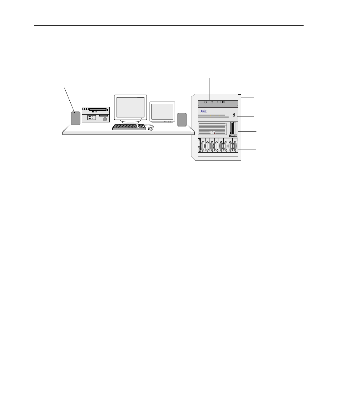
NewsCutter Layout
Figure 1 shows all standard and optional NewsCutter components
except for a video reference source (such as a black burst generator).
Set up your system components — especially the User Interface (UI)
and Playback monitors, video deck, and keyboard — in positions that
give you easy access to them.
Avid NewsCutter Site Preparation
Page 17
SCSI ID
Slots
Act
Wide
Dualbus
Fans
Pwr 2
Pwr 1
V-LAN VLXi device
17
Video deck
Speaker UI monitor
Keyboard
Figure 1 Sample NewsCutter System Layout
The NewsCutter system has the following features:
• Internal hard drive with an NTFS partition; primary drive that
contains the operating system.
• 3.5-inch floppy drive; reads and writes to 1.44-MB floppy disks.
• CD-ROM reader; required for installing software. Avid software is
distributed on CD-ROM.
• Fast and wide external SCSI connector; for connecting external
SCSI media drives. Media drives must be formatted as NTFS.
Playback monitor
Mouse
Speaker
Amplifier
VLX
44.1 kHz
kHz
48
D
I
I
S
C
S
s
t
lo
S
t
c
A
e
id
W
s
u
lb
a
u
D
s
n
a
F
2
r
w
P
1
r
w
P
Optional rack
O
l
PULL DOWN
AUDIO SYNC
POWER
VIDEO SYNC
Meridien I/O box
NewsCutter
MediaDock device
• Ethernet network interface; required for Avid network
connections.
• High-resolution monitor (1024 x 768); required for viewing the
media edits.
• Windows 2000 operating system and the Windows
Service Pack 2.
Avid System Layouts
Page 18

18
Avid Unity for News Workgroup Layout
n
NewsCutter can work as a standalone system or as part of a broadcast
network such as an Avid Unity
The Avid Unity for News workgroup environment consists of the
following functional components:
• Supported Avid editing systems (such as a NewsCutter system).
• Avid Unity MediaManager server to track and manage Avid Unity
media files. When connected to a Fibre Channel network, a
workgroup client uses the MediaManager server to share
Avid Unity files with clients within the workgroup.
• Avid Unity TransferManager server to manage the transfer of
media files to and from another workgroup’s TransferManager
server (typically, over an Ethernet network). The TransferManager
server also allows you to transfer media files from a feed (ingest)
device or send finished sequences to a playback device.
The TransferManager server is not required equipment in a MediaNet
workgroup. However, you must connect a TransferManager server in your
workgroup if you want to share media files with other workgroups.
• Avid Unity MediaNet File Manager and storage subsystem.
™
for News workgroup.
• A Fibre Channel network that connects the Avid editing systems,
n
Avid NewsCutter Site Preparation
An optional Fibre Channel connection kit is available for connecting
NewsCutter to the Avid Unity MediaNet workgroup.
• An Ethernet network that is used as a general-purpose
MediaManager server, and TransferManager server to the File
Manager and storage subsystem.
communications network connecting all the system components.
An Ethernet network can also be used by the TransferManager
server to transfer media files between workgroups.
Page 19

19
Avid Unity
y
The purpose of the workgroup is to enable collaborative workflows by
allowing multiple NewsCutter editors to share media files and other
project data.
Figure 2 shows a typical shared-storage workgroup configuration that
includes the necessary connections if you are planning to transfer
media files over a network to an optional playback device. The
playback sequences are cued and sent to air by the optional Broadcast
Control System (BCS). The BCS controls the playback devices using a
serial connection.
Fibre Channel switch
TransferManager server
to another workgroup
Playback
device
MediaManager
server
Still store
Broadcast Control
System
Local network
hub or switch
Character
generator
Serial connections to
playback devices
NewsCutter systems
(see Figure 1 for a
typical layout)
MediaNet File
Manager and
Avid Unity
storage
Figure 2 Sample Layout for an Avid Unity for News
Workgroup Environment
Avid System Layouts
Page 20

20
n
Follow the procedures in the Avid Unity MediaNet Windows Client
Setup Guide in order to make your NewsCutter system operational in the
Avid Unity environment.
Fibre Channel Workgroup Configuration
An optional Fibre Channel connection kit is available for NewsCutter.
If you are installing a Fibre Channel connection kit, follow the
instructions provided by the computer manufacturer for removing the
cover and installing an expansion board in NewsCutter.
NewsCutter Connectors
The NewsCutter system is a computer with specific peripheral boards
installed for converting the incoming video and audio, analog, or
digital signals into digital format for storage. The Windows 2000,
Windows
preinstalled. This disk-based, nonlinear, random-access system is
designed for editing news stories, promotional material, and other
broadcast needs.
Service Pack 2, and NewsCutter application software come
Avid NewsCutter Site Preparation
Page 21
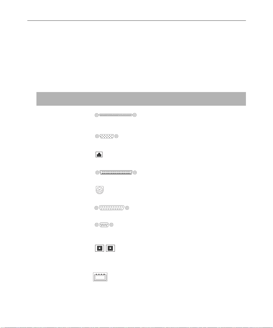
Table 1 provides a description of each system or peripheral board
connector. Avid customers sometimes request pin assignments for
customizing their interface cables. See “Pin Assignments” on page 38
for information on which signals are on which pins.
Table 1 NewsCutter Connector Identifiers
Connector Name Connector Function
21
Digital media board
(M port)
VGA VGA output from standard VGA board, 15-pin
Network Network interface, RJ-45 network jack
SCSI SCSI port, fast and wide interface, 68-pin female
PS/2-style Two PS/2-style connectors (keyboard and mouse),
Parallel Parallel port, 25-pin female DB-connector; connects
COM1 and COM2 Two serial ports, 9-pin male DB-connector;
Fibre Channel Rx and Tx
(option)
Interface between NewsCutter and the Avid
Meridien™ I/O box (Avid proprietary cable,
shipped with NewsCutter)
DB-connector; connects to VGA interconnect cable
DB-connector; connects MediaDrives
6-pin
application key and local printer
connects the serial adapter for remote video deck
control
Fibre Channel adapter board, receive and transmit
optical interface connectors (needed for Avid
workgroup configurations); also has two 9-pin
female DB connectors
Universal Serial Bus
(USB)
USB port; connects USB application key and MIDI
converter
Avid System Layouts
Page 22
22
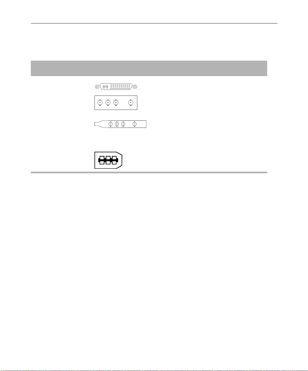
Table 1 NewsCutter Connector Identifiers (Continued)
Connector Name Connector Function
SDTI board
(NewsCutter only option)
MPEG SDTI-CP board
(NewsCutter only option)
1394 connector
(NewsCutter XP only)
Input and Output Connections
NewsCutter and NewsCutter XP handle input and output of media
differently:
• NewsCutter uses the Avid Meridien I/O box to control all video
and audio input and output.
• NewsCutter XP uses an OHCI-compliant 1394 board to connect to
a digital video (DV) device such as a video deck, digital camera, or
transcoder.
Serial Data Transport Interface board; contains
receive and transmit male multipin connector that
connects to female multipin connector on breakout
box, which connects to a video deck through a
cable
Serial Data Transport Interface adapter board,
optimized for MPEG 50; contains four BNC
connectors that connect through cables to an
MPEG SDTI-CP video deck
OHCI-compliant 1394 board; contains two 6-pin
connectors that connect NewsCutter XP to
transcoders and digital video devices
Avid NewsCutter Site Preparation
Page 23

Avid Meridien I/O Box Connectors
The Avid Meridien I/O box provides all the audio and video input
and output connections for the NewsCutter system (including
four-channel audio with the second audio interface installed). Figure 3
identifies the audio connectors. See Tabl e 2 for a description of each
connector.
23
10
1
11
12
13
2
4
3
14
5
16
15
6
7
18
17
8
9
Figure 3 Meridien I/O Box Audio Connectors
Avid System Layouts
Page 24

24
Table 2 Meridien I/O Box Audio Identifiers
Number Label Function
1 AUDIO IN MIC Microphone audio input, female connector
2 AUDIO IN CHAN 1 Channel 1 audio input, female connector
3 AUDIO IN CHAN 2 Channel 2 audio input, female connector
4 AUDIO OUT CHAN 1 Channel 1 audio output, male connector
5 AUDIO OUT CHAN 2 Channel 2 audio output, male connector
6 AES/EBU IN AES/EBU digital input, female connector
7 AES/EBU OUT AES/EBU digital output, male connector
8 S/PDIF IN S/PDIF digital input, phono (RCA
®
) jack
9 S/PDIF OUT S/PDIF digital output, phono (RCA) jack
a
10
AUDIO IN MIC Microphone audio input 2, female connector (not used)
11 AUDIO IN CHAN 1 Channel 3 audio input, female connector
12 AUDIO IN CHAN 2 Channel 4 audio input, female connector
13 AUDIO OUT CHAN 1 Channel 3 audio output, male connector
14 AUDIO OUT CHAN 2 Channel 4 audio output, male connector
15 AES/EBU IN AES/EBU digital input 2, female connector
16 AES/EBU OUT AES/EBU digital output 2, male connector
17 S/PDIF IN S/PDIF digital input 2, phono (RCA) jack
18 S/PDIF OUT S/PDIF digital output 2, phono (RCA) jack
a. NewsCutter can use only one microphone audio input.
Avid NewsCutter Site Preparation
Page 25

25
Figure 4 identifies the video connectors on the Meridien I/O box. See
Table 3 for a description of each connector.
1
3
5
16
2
14
15
6
4
12
13
1117 9
7
10
8
Figure 4 Meridien I/O Box Video Connectors
Table 3 Meridien I/O Box Video Identifiers
Number Label Function
1 COMPONENT Y IN Video Y component input, BNC connector. Connects to
analog video output of decks, satellite feeds, or routers.
2 COMPONENT R-Y IN Video R-Y component input, BNC connector. Connects to
analog video output of decks, satellite feeds, or routers.
3 COMPONENT B-Y IN Video B-Y component input, BNC connector. Connects to
analog video output of decks, satellite feeds, or routers.
4 COMPONENT Y OUT Video Y component output, BNC connector. Connects to
analog video input of decks or routers.
5 COMPONENT R-Y OUT Video R-Y component output, BNC connector. Connects to
analog video input of decks or routers.
Avid System Layouts
Page 26

26
Table 3 Meridien I/O Box Video Identifiers (Continued)
Number Label Function
6 COMPONENT B-Y OUT Video B-Y component output, BNC connector. Connects to
analog video input of decks or routers.
7 SYSTEM IN/OUT Audio and video I/O connector from NewsCutter.
8 LTC OUT Longitudinal timecode (LTC) output, male connector
(timecode output currently is not functional).
9 LTC IN Longitudinal timecode input, female connector. Master
clock used to synchronize NewsCutter to the house master
clock (SMPTE for NTSC, and EBU for PAL).
10 SLAVE CLOCK OUT Clock output, BNC connector. Used to synchronize other
broadcast components.
11 S-VIDEO OUT Super composite video output, 4-pin connector. Connects to
analog video input of decks or routers.
12 COMPOSITE OUT 3 Composite video output, BNC connector. Connects to
analog video input of decks, monitors, or routers.
13 COMPOSITE OUT 2 Composite video output, BNC connector. Connects to
analog video input of decks, monitors, or routers.
14 COMPOSITE OUT 1 Composite video output, BNC connector. Connects to
analog video input of decks, monitors, or routers.
15 S-VIDEO IN Super composite video input, 4-pin connector. Connects to
analog video output of decks, satellite feeds, or routers.
16 COMPOSITE IN Composite video input, BNC connector. Connects to analog
video output of decks, satellite feeds, or routers.
17 Video Reference (REF) Black burst input, BNC connector. Synchronizes decks and
V-L AN
®
VLXi® controller that are part of the system.
Avid NewsCutter Site Preparation
Page 27

27
Figure 5 identifies the optional serial digital connectors on the Meridien
I/O box. See Table 4 for a description of each connector.
n
Avid NewsCutter Setup Guide.
1
2
4
3
Figure 5 Meridien I/O Box Serial Digital Connectors
Table 4 Meridien I/O Box Serial Digital Identifiers
Number Label Function
1 SERIAL DIGITAL IN Composite video input, BNC connector. Connects to digital
video output of decks, satellite feeds, or routers.
Instructions for installing the optional serial digital board are provided in the
2 SERIAL DIGITAL OUT 1 Composite video output, BNC connector. Connects to
digital video input of decks, monitors, or routers.
3 SERIAL DIGITAL OUT 2 Composite video output, BNC connector. Connects to
digital video input of decks, monitors, or routers.
4 SERIAL DIGITAL OUT 3 Composite video output, BNC connector. Connects to
digital video input of decks, monitors, or routers.
Avid System Layouts
Page 28

28
1394 Board Connectors
Transcoders and DV devices, such as digital video decks and digital
cameras, connect to a 1394 PCI board installed on your
NewsCutter XP system (see the Avid NewsCutter XP Setup Guide for
more information on installing the 1394 board). You can use either a
6-pin cable or a 4-to-6-pin 1394 converter cable to connect digital
devices to NewsCutter XP. Figure 6 illustrates the connections on the
1394 board.
Figure 6 1394 Board DV Connectors
Cabling Guidelines
DV
6-pin 6-pin
6-pin connectors
The customer is responsible for the audio, video, network, and serial
cables. Lengths are determined by the customer’s needs. A floor plan
of the facility, with the locations marked where the users and
equipment are located, will help plan the cabling needs. Avid does not
recommend excessively long cables.
Avid NewsCutter Site Preparation
Page 29

Table 5 lists the standard and maximum lengths that Avid
recommends for the system cables.
29
n
equipment.
Table 5 System Cable Lengths
Cable Standard Length Maximum Length Connects
These guidelines refer to the cable lengths and not the physical distances of the
Power cables 6 ft (1.8 m)
Included with system
components
Keyboard cable 6 ft (1.8 m)
Attached to keyboard
Mouse cable 6 ft (1.8 m)
Attached to mouse
Mouse extension cables longer than 25 feet (7.6 meters) can negatively
c
impact system performance. Longer cables cause signal degradation and
might require a booster.
A quality power strip
can be used (not
supplied).
Up to 12 ft (3.7 m)
A quality PS/2
extender cable can be
used (not supplied).
Up to 12 ft (3.7 m)
A quality PS/2
extender cable can be
used (not supplied).
NewsCutter and system
components to ac source (or
power strip)
Keyboard to NewsCutter
Mouse to NewsCutter
User Interface (UI)
monitor cable
Meridien digital
media cable
(NewsCutter option)
6 ft (1.8 m)
Included with monitor
Monitor extension cables longer than 25 feet (7.6 meters) can negatively
c
impact system performance. Longer cables cause signal degradation and
might require a booster.
6 ft (1.8 m)
Included with
Meridien I/O box
Up to 15 ft (4.6 m)
A quality VGA
extender cable can be
used (not supplied).
50 ft (15.2 m)
Optional through
Av id
UI monitor to NewsCutter
Meridien I/O box to
NewsCutter
Avid System Layouts
Page 30

30
Table 5 System Cable L engths (Continued)
Cable Standard Length Maximum Length Connects
IEEE 1394 cable
(NewsCutter XP
option)
SCSI cable
(optional)
Fiber-optic cable
(optional)
Remote-control
serial cable
GPI control cable Customer supplied Up to 25 ft (7.6 m) GPI controller to
V-LAN VLXi cable Customer supplied Up to 25 ft (7.6 m) VLXi to NewsCutter
Speaker cable Customer supplied Up to 20 ft (6.1 m) Speaker to amplifier
14.7 ft (4.5 m) 236 ft (72.0 m) Transcoder or DV device to
NewsCutter XP
Customer supplied Up to 6 ft (1.8 m)
Optional through
Av id
The last SCSI device in the SCSI chain must be terminated. Terminators are
n
customer supplied and are available through Avid.
Customer supplied 50 micron, up to
1650 ft (503.0 m)
65 micron, up to
577.5 ft (176.0 m)
12 ft (3.6 m)
Included with system
100 ft (30.5 m)
Limit imposed by
RS-422 requirements
SCSI devices (MediaDock™
and MediaDrive) to
NewsCutter
NewsCutter clients and
playback devices to Fibre
Channel hub (fiber-optic cables
must be industry certified)
Video deck to NewsCutter
NewsCutter
BNC video
reference cables
BNC video cables
(analog or digital)
Avid NewsCutter Site Preparation
Customer supplied Up to 25 ft (7.6 m) Black burst generator or
Customer supplied Up to 25 ft (7.6 m) NewsCutter to
reference video source to
deck, NewsCutter, and
V-LAN VLXi
customer-supplied equipment
(such as a deck, satellite feed,
and Playback monitor)
Page 31

Table 5 System Cable L engths (Continued)
Cable Standard Length Maximum Length Connects
31
BNC timecode
cables
Printer cable Customer supplied 6 ft (1.8 m) NewsCutter to
RJ-45 Category 5
cables
Customer supplied Up to 25 ft (7.6 m) V-LAN VLXi to deck (required
only if deck does not have a
built-in timecode)
customer-supplied printer
Customer supplied Up to 330 ft (100.5 m) Ethernet hub to NewsCutter
clients, playback devices,
and BCS
Component Dimensions and Weights
Table 6 provides the dimensions and weights of the NewsCutter
system components.
Table 6 Physical Specifications for Components
Component
Rackmount
Rack
Units Height x Width x Depth Wei ght
Meridien I/O box
(includes a two-channel audio
interface and video interface; the
serial digital interface is optional)
NewsCutter
(Compaq Evo Workstation W8000)
Audio amplifier Yes 1 2.0 x 19.0 x 12.0 in
Yes 3 5.2 x 17.3 x 7.6 in
(13.2 x 43.9 x 19.3 cm)
Yes 5 17.8 x 8.0 x 23.3 in
(45.2 x 20.4 x 59.2 cm)
(5.1 x 48.3 x 30.5 cm)
Component Dimensions and Weights
15.5 lb
(7.0 kg)
48.0 lb
(21.8 kg)
14.0 lb
(6.4 kg)
Page 32

32
Table 6 Physical Specifications for Components (Continued)
Component
Rackmount
Rack
Units Height x Width x Depth Wei ght
External drives
MediaDrive rS LVD (with
interlocking stacking brackets)
MediaDock LVD rackmount
(includes a maximum of eight
MediaDock Shuttle
™
drives and
two power supplies)
Yes 2 3.1 x 8.2 x 9.9 in
(7.9 x 20.8 x 25.1 cm)
Ye s 4
+ 1 for
5.3 x 17.6 x 16.3 in
(13.5 x 44.7 x 41.4 cm)
cables
7.1 lb
(3.2 kg)
63.0 lb (28.6 kg)
(includes two
power supplies
and eight drives)
Monitor
21-inch monitor No — 19.3 x 19.7 x 19.2 in
(49.0 x 50.0 x 48.8 cm)
17-inch monitor No — 16.0 x 16.0 x 17.0 in
(40.6 x 40.6 x 43.2 cm)
Playback monitor
—— — —
77.0 lb
(35.0 kg)
38.0 lb
(17.2 kg)
(customer supplied)
Video input/output hardware (to be used with customer-supplied decks, satellite feeds, or routers)
GPI controller Yes 1 1.7 x 17.0 x 10.5 in
(4.4 x 43.2 x 26.7 cm)
Black burst generator No — 1.7 x 7.0 x 8.0 in
(4.4 x 17.8 x 20.3 cm)
V-LAN and VLXi Yes 1 1.7 x 19.0 x 11.0 in
(4.4 x 48.3 x 27.9 cm)
Avid NewsCutter Site Preparation
9.0 lb
(4.1 kg)
1.9 lb
(0.9 kg)
8.5 lb
(3.8 kg)
Page 33

Site Requirements
The following are the site requirements for NewsCutter.
Power Requirements
Avid strongly recommends using a surge protector and an
uninterruptible power supply (UPS). If the computer loses power even
for a moment, the entire system will stop functioning. There must be a
20-A, 110- to 120-Vac, 60-Hz circuit or a 10-A, 220- to 224-V ac, 50-Hz
circuit for each NewsCutter system. The circuit must have a dedicated
circuit breaker and an isolated ground.
Storage upgrades might require additional electrical service. Take into
consideration the equipment nameplate ratings when addressing this
concern. Consult your Avid representative.
33
w
Systems are designed to work with a single-phase (three-wire)
power cord with a grounded neutral conductor. To reduce the risk of
electric shock, always plug the cord into a grounded power outlet.
For best performance, keep all system power connections on the same
power feed distribution panel. Do not connect fans, lamps, coffee pots,
or other equipment to the same outlet that is powering the Avid
equipment.
Site Requirements
Page 34

34
Table 7 lists the power requirements for individual system
components. Surge protectors and a UPS are recommended but are not
supplied by Avid.
Table 7 Power Requirements
Item Type Voltage Frequency Power
Meridien I/O box Autosensing 100 to 120 V ac
220 to 240 V ac
NewsCutter
(Compaq Evo Workstation W8000)
Audio amplifier (optional) Autosensing 110 V ac
Disk drive systems
MediaDrives Autosensing 100 to 120 V ac
MediaDock Switch
Monitors
21-inch UI monitor Autosensing 100 to 120 V ac
17-inch UI monitor Autosensing 100 to 120 V ac
Playback monitor (user
supplied; requirements vary)
Autosensing 90 to 132 V ac
180 to 264 V ac
220 Vac
200 to 240 V ac
83 to 245 V ac 47 to 63 Hz 140 W (idle)
selectable
200 to 240 V ac
200 to 240 V ac
—— ——
60 Hz
50 Hz
60 Hz
50 Hz
60 Hz
50 Hz
60 Hz
50 Hz
60 Hz
50 Hz
60 Hz
50 Hz
65 W
500 W
maximum
35 W
40 W
200 W (max.)
150 W
120 W
Avid NewsCutter Site Preparation
Page 35

Table 7 Power Requirements (Continued)
Item Type Voltage Frequency Power
Video and input/output
hardware
GPI controller Autosensing 90 to 240 V ac 47 to 63 Hz 30 W
35
Black burst generator Switch
selectable
V-LAN and VLXi Autosensing 120 V ac
Source Requirements
Avid systems accept video and audio that adhere to broadcast
standards. Excessive jitter and noise on a signal is not an acceptable
source. All video sources need to be synchronized.
Synchronization Requirements
A stable video reference source is required for synchronizing the
system. Use 75-ohm coaxial cables when you are connecting the
reference signal. You can use a black burst generator as the video
reference source.
120 V ac
240 Vac
220 Vac
60 Hz
50 Hz
60 Hz
50 Hz
20 W
20 W
Printing Requirements
NewsCutter uses standard 25-pin parallel printing capabilities. The
parallel port is AT-compatible, supporting bidirectional, EPP, and ECP
protocols. You can use network printers via Ethernet connections.
Site Requirements
Page 36

36
Telephone Requirements
Systems do not include a modem. Communication outside the
NewsCutter system should be done through the network board. A
telephone near the system is recommended if you need to
communicate with your Avid representative. Avid encourages all
customers to use the Avid Customer Support Knowledge Center to
access the latest news.
Environmental Requirements
Table 8 lists the environmental specifications for a standard
NewsCutter environment. The air conditioning must maintain the
operating temperature listed.
c
Avid reserves the right to stop the installation and shut off the Avid
equipment if the temperature exceeds 75°F (24°C). Installation will
be completed once the air conditioning has been corrected.
Table 8 Environmental Specifications
Condition Range
Operating temperature 50°F to 75°F (10°C to 24°C)
Storage temperature –4°F to 140°F (–20°C to 60°C)
Relative humidity 20% to 80%
Altitude 0 to 6000 ft (0 to 1829 m)
Avid NewsCutter Site Preparation
Page 37

Networking Requirements
NewsCutter is designed to work over industry-standard local area
networks (LANs) and wide area networks (WANs), using standard
networking protocols. The NewsCutter system uses an Ethernet
100BASE-T connection. Avid recommends you use a Category 5
unshielded twisted-pair (UTP) cable when connecting NewsCutter to
a network.
Install network cabling before the equipment arrives (for example, lay
out the network cables between rooms before setting up the
equipment). Make a note of all the network IP addresses (clients,
printers, playback devices).
Fiber-Optic Switch
NewsCutter transfers the finalized sequences to the playback device
through a Fibre Channel switch connection. Typically, fiber-optic cable
is run along or inside ductwork. Fiber-optic cable is made of optical
fibers, fine strands of glass, or other transparent material, and is not
resilient by nature.
37
Ethernet Hub
The Ethernet hub connects NewsCutter clients to Avid broadcast
network segments. Ethernet hubs have multiple RJ-45 ports that
connect all the network devices. When a packet arrives at one port, it is
copied to all the other ports so all segments of the LAN can see all
packets.
A 100BASE-T Ethernet hub is required when connecting within a
production workgroup. Typically, status LEDs on the hub show valid
connections or network activity.
Site Requirements
Page 38

38
Patch Panel
A patch panel is used as a junction box to centralize all the incoming
connections from the workstations and network devices in the
computer room. The incoming connections access the system through
the patch panel. Patch panels allow you to reconfigure and diagnose
the system with minimal effort; failed computer components can be
bypassed easily. Avid recommends the system administrator keep a
log of each device connected to the patch panel.
The customer is responsible for running the cable from the computer
room to each distribution point. In turn, the distribution points
connect each network device (printers, teleprompters, and wire
services) via a Category 5 cable.
Pin Assignments
The following sections provide the pin assignments for the
NewsCutter connectors.
Serial Ports
NewsCutter has two serial ports (COM1 and COM2). The ports can be
internally configured to communicate in RS-232 and RS-422 protocol.
The NewsCutter serial ports use 9-pin male connectors.
Avid NewsCutter Site Preparation
Page 39
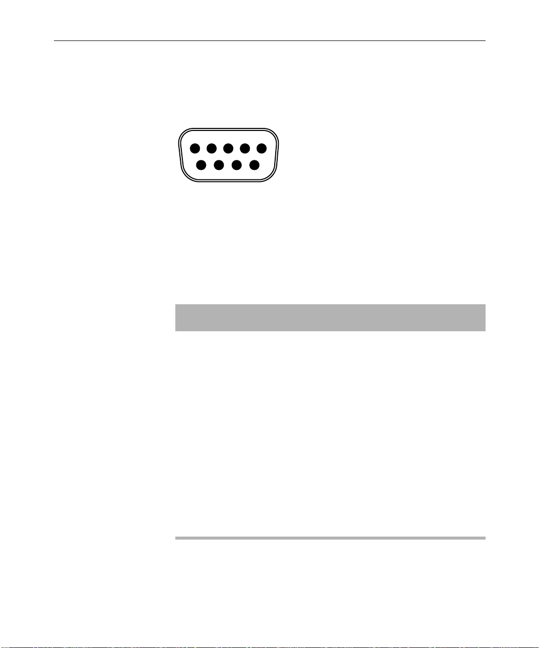
Figure 7 shows the connector pinouts.
39
51
96
15
67
Figure 7 9-Pin Serial Connector
Table 9 lists the pin assignments for the serial connectors. Not all serial
devices use every signal.
Table 9 Serial Connector Pin Assignments
Pin RS-232 Signal RS-422 Signal
1 Data carrier detect Ground
2 Receive data Transmit data –
3 Transmit data Receive data +
4 Data terminal ready Receive common
5 Ground Not used
6 Data set ready Transmit common
7 Request to send Transmit data +
8 Clear to send Receive data –
9 Ring indicator Ground
Pin Assignments
Page 40

40
VGA Monitor Port
The UI Monitor port uses a 15-pin female VGA connector. Figure 8
shows the connector pinouts.
Figure 8 15-Pin VGA Monitor Connector
Table 1 0 lists the pin assignments for the VGA UI monitor connector.
Table 10 VGA Monitor Connector Pin
15
610
1115
Assignments
Pin Signal
1Red video
2Green video
3Blue video
4Ground
5 Display Data Channel Ground
6Red Ground
7Green Ground
8Blue Ground
9 Not used
Avid NewsCutter Site Preparation
Page 41

Table 10 VGA Monitor Connector Pin
Assignments (Continued)
Pin Signal
10 SYNC Ground
11 Ground
12 Serial Data
13 Horizontal SYNC
14 Vertical SYNC
15 Serial Clock
Keyboard and Mouse Connectors
41
NewsCutter provides two PS/2-style 6-pin female connectors for the
keyboard and mouse. Figure 9 shows the connector pinouts.
56
4
21
3
Figure 9 6-Pin PS/2 Connector
Pin Assignments
Page 42

42
Table 11 lists the pin assignments for the PS/2-style connector.
Table 11 PS/2 Connector Pin Assignments
Keyboard/Mouse Pin Signal
1 Data
2 NC
3 Ground
4 +5 volts
5 Clock
6 NC
NC – no connection
RJ-45 Jacks
Category 5 UTP cable supports up to 1 Gb/s (1000 Mb/s). The cable
contains four twisted pairs of wires, for a total of eight wires. Avid
recommends using Category 5 cables for serial connections whenever
possible.
The four pairs of wires in UTP cable are colored so they can be
identified at each end of the cable. Typically, the pairs are made up of a
solid color wire and the same color wire striped with white.
Avid NewsCutter Site Preparation
Page 43

43
Figure 10 shows the standard connector pinouts for an 8-pin RJ-45 jack
(used on Category 5 cables).
18
Figure 10 8-Pin Category 5 RJ-45 Connector
Table 1 2 lists the pin assignments with color code according to the
IEEE specification for an EIA/TIA-568B RJ-45 wiring scheme. Not all
devices use every pin. Pairs are identified by colors. Ethernet
100BASE-T data connections use only the orange (pins 1 and 2) and
green pairs (pins 3 and 6).
Table 12 Category 5 RJ-45 Connector Pin Assignments
Pin Color Code
1 Orange/white stripe
2Orange
3 Green/white stripe
4Blue
5Blue/white stripe
6 Green
7Brown/white stripe
8Brown
Pin Assignments
Page 44

44
1394 Connector (NewsCutter XP Only)
The OHCI-compliant 1394 board contains a Texas Instruments® chip
set and two 6-pin 1394 connectors (see Figure 11). 1394 cables contain
two sets of twisted-pair wires carrying signals between DV devices
and NewsCutter XP. For a list of qualified boards, see your Avid
Reseller.
24 6
135
Figure 11 6-Pin 1394 Connector
Table 1 3 lists the standard pin assignments for 6-pin 1394 connectors.
Table 13 6-Pin 1394 Connector Pin Assignments
Pin Signal
1Bus power
2Ground
3 TPB– (data negative)
4 TPB+ (data positive)
5 TPA– (data negative)
6 TPA+ (data positive)
Avid NewsCutter Site Preparation
Page 45

GPI Connector
45
The Videomedia
®
VLXi-GT GPI controller contains six programmable
general-purpose interface (GPI) inputs/outputs with quick-disconnect
terminal connectors. Each connector contains three terminals: the left
terminal is the GPI input, the center terminal is the GPI ground, and
the right terminal is the GPI output. Remove about 1/4-inch of
insulation from the appropriate wire and then insert the bare wire into
the appropriate terminal. Turn the screw directly above the terminal
clockwise to secure the wire in the connector. Figure 12 shows the
node terminals on the GPI controller.
SERIAL
1 2 3 4 5 6
Figure 12 GPI Node Terminals
SDTI Connectors (NewsCutter Only Option)
The SDTI adapter option in NewsCutter connects to a breakout box
containing four BNC connectors. Figure 13 identifies the signals for
each connector on the breakout box.
OUTIN OUT IN OUT IN OUT IN OUT IN OUT
IN
SDI/SDTI Out SDI/SDTI Loop Out SDI/SDTI In Ref In
Figure 13 BNC Connectors on the Breakout Box
Pin Assignments
Page 46

46
The MPEG SDTI-CP option does not connect to a breakout box. Instead,
cables from the MPEG SDTI-CP video deck connect directly to the
BNC connectors on the optional MPEG SDTI-CP adapter board.
Figure 14 identifies the signals for each connector on the adapter
board.
SDTI Out SDTI In Reference Loop (Passthrough) Ref In
Figure 14 BNC Connectors on the MPEG SDTI-CP Adapter
Board
Avid NewsCutter Site Preparation
Page 47

FCC Notice
Regulatory and Safety Notices
This device complies with Part 15 of the FCC Rules. Operation is
subject to the following two conditions:
1. This device may not cause harmful interference.
2. This device must accept any interference received, including
interference that may cause undesired operation.
This equipment has been tested and found to comply with the limits
for a Class A digital device, pursuant to Part 15 of the FCC Rules.
These limits are designed to provide reasonable protection against
harmful interference when the equipment is operated in a commercial
environment. This equipment generates, uses, and can radiate radio
frequency energy and, if not installed in accordance with the
instruction manual, may cause harmful interference to radio
communications. Operation of this equipment in a residential area is
likely to cause harmful interference in which case the user will be
required to correct the interference at his own expense.
Page 48

48
Canadian ICES-003
This Class A digital apparatus meets all requirements of the Canadian
Interference Causing Equipment Regulations.
Cet appareil numérique de la classe A respecte toutes les exigences du
Règlement sur le matériel brouilleur du Canada.
European Union Notice
Declaration of Conf ormity
(According to ISO/IEC Guide 22 and EN 45014)
Regulatory and Safety Notices
Application of Council
Directives:
Standards to which
Conformity is Declared:
Manufacturer’s Name: Avid Technology, Inc.
European Contact: Nearest Avid Sales and Service Office or
Type of Equipment: Information Technology Equipment
73/23/EEC, 89/336/EEC.
EN60950:1992 + A1 + A2 + A3 + A4 + A11
CISPR 22:1985 / EN55022:1988 Class A
EN55024:1998/EN61000 — 3-2, 4-2, 4-3, 4-4, 4-5, 4-6,
4-8, 4-11
1925 Andover Street
Tewksbury, MA 01876, USA
Avid Technology International B.V.
Sandyford Business Center
Unit 3,
Dublin 18, Ireland
Page 49

49
Product Name: Products for the Windows NT or Windows 2000
Operating System: Media Composer,
Film Composer, Avid Xpress, Avid Xpress DV,
Avid Unity, Avid|DS, NewsCutter, NewsCutter XP,
NewsCutter DV, Symphony
Products for the Macintosh Operating System:
Media Composer, Film Composer, Avid Xpress,
Av id U ni ty
Products for the UNIX Operating System: AirPlay,
VideoSPAC E
Base Model Numbers: None
Product Options: All
Year of Manufacture: 2002
(1) Products for the Windows NT or Windows 2000 Operating System:
products were tested in a typical Media Composer, Film Composer,
Avid Xpress , Avid X press DV, Avid U n ity, Avid|DS, NewsCutter,
NewsCutter XP, NewsCutter DV, or Symphony configuration.
(2) Products for the Macintosh Operating System: products were
tested in a typical Media Composer, Film Composer, Avid Xpress, or
Avid Unity configuration.
(3) Products for the UNIX Operating System: products were tested in
an AirPlay or VideoSPACE configuration.
I, the undersigned, hereby declare that the equipment specified above
conforms to the above Directives and Standards.
George R. Smith, Director of Hardware Engineering.
European Union Notice
Page 50

50
Australia and New Zealand EMC Regulations
John Kells, Australian Operations Manager
N1709
Avid Technology (Australia)
Unit B
5 Skyline Place
French Forest NSW 2086
Australia
Phone: 61-2-8977-4800
Taiwan EMC Regulations
Taiwan EMC Regulations BSMI Class A EMC Warning
Regulatory and Safety Notices
Page 51

Index
A B C D E F G H K L M N P R S T U V W
Numerics
1394
cables
30
connectors 22, 28
A
Audio
dimensions
power 34
Avid system
components
linking 37
Avid system components
dimensions
31
16
31, 34
B
Basic system setup 16
Black burst generator
dimensions
power 35
32
C
Cables
Avid-supplied
Cabling
guidelines
Category 5
description
Components
dimensions
Connectors
1394
22, 28
GPI 45
keyboard 41
RJ-45 43
SDTI 22, 45
SDTI-CP 22, 45, 46
serial 38
UI monitor 40
29
28
42
31
D
Device
connections
Dimensions of components 31
38
Page 52

52
Drives
dimensions
power 34
32
E
Enhanced system setup 16
Environmental requirements 36
F
Fibre Channel 18, 20
G
General-purpose interface (GPI)
connectors
controller power requirements 35
controller specifications 32
Grounding 33
45
H
House clock 26
M
MediaDock
dimensions
power 34
MediaDock Shuttle 32
MediaServer
components
console 17
Monitors
dimensions
power 34
32
17
32
N
Network
connections
Ethernet hub 37
site 37
Network connection 37
Networking
requirements
NewsCutter
layout
Newsroom Computer System
Ethernet hub
patch panel 38
37
37
16
37
K
Keyboard
connector
41
L
Layout
NewsCutter
Linking Ethernet connections 37
16
P
Patch panel
description
Physical dimensions 31
Pin assignments
1394
GPI 42
keyboard 42
remote control 42
RJ-45 43
38
44
Page 53

53
serial 39
UI monitor 40
Ports See Connectors
Power
connections
requirements 33
specifications 34
Printing requirements 35
33
R
Requirements See Site requirements
S
SDTI-CP 22, 45
Serial connector 38
Serial Data Transport Interface (SDTI) 22
Setting up
work environment
Site network 37
Site requirements
environmental
network 37
power 33
printing 35
source 35
synchronization 35
telephone 36
Source requirements 35
Specifications
environmental
mechanical 31
power 34
Surge protector 33, 34
Synchronization requirements 35
System layouts 16
16 to 20
36
36
T
Telephone requirements 36
U
Uninterruptible power supply See UPS
UPS (uninterruptible power supply)
description
UTP (unshielded twisted pair) 42
33
V
V-LAN VLXi
dimensions
requirements 35
32
W
Weights of components 31
Work environment
setting up
16
Page 54

54
 Loading...